volume 3 of 8 … · project manager electrical engineer works secretary chief engineer...
TRANSCRIPT

VOLUME 3 of 8
ELECTRICAL INSTALLATIONWORKS
[ADMINISTRATION BLOCK – DONGO KUNDUINDUSTRIAL PARK]

REPUBLIC OF KENYA
MINISTRY OF INDUSTRIALIZATION, TRADE ANDENTERPRISE DEVELOPMENT
SPECIAL ECONOMIC ZONES AUTHORITY (SEZA)
PROPOSED ADMINISTRATION BLOCK FOR SPECIAL ECONOMIC ZONESAUTHORITY (SEZA) AT DONGO KUNDU INDUSTRIAL PARK, MOMBASA
W.P. ITEM NO. D117 CO/MSA/1902 JOB NO. 10676B
TENDER SPECIFICATIONS & BILLS OF QUANTITIES FOR
SUPPLY, INSTALLATION, TESTING AND COMMISSIONING OF ELECTRICAL
INSTALLATION WORKS
CLIENTCHIEF EXECUTIVE OFFICERSPECIAL ECONOMIC ZONES AUTHORITY (SEZA)P.O BOX 30418 - 00100NAIROBI
PROJECT MANAGER ELECTRICAL ENGINEERWORKS SECRETARY CHIEF ENGINEER (ELECTRICAL)MINISTRY OF TRANSPORT, INFRASTRUCTURE, PUBLIC MINISTRY OF TRANSPORT, INFRASTRUCTURE, PUBLICWORKS, HOUSING & URBAN DEVELOPMENT WORKS, HOUSING & URBAN DEVELOPMENTSTATE DEPARTMENT OF PUBLIC WORKS, STATE DEPARTMENT OF PUBLIC WORKS,P.O BOX 30743 – 00100, P.O BOX 41191 – 00100,NAIROBI NAIROBI
ARCHITECT QUANTITY SURVEYORCHIEF ARCHITECT CHIEF QUANTITY SURVEYORMINISTRY OF TRANSPORT, INFRASTRUCTURE, PUBLIC MINISTRY OF TRANSPORT, INFRASTRUCTURE, PUBLICWORKS, HOUSING & URBAN DEVELOPMENT WORKS, HOUSING & URBAN DEVELOPMENTSTATE DEPARTMENT OF PUBLIC WORKS, STATE DEPARTMENT OF PUBLIC WORKS,P.O BOX 30743 – 00100, P.O BOX 30743 – 00100,NAIROBI NAIROBI
STRUCTURAL ENGINEER MECHANICAL ENGINEERCHIEF ENGINEER (STRUCTURAL) CHIEF ENGINEER (MECHANICAL (BS))MINISTRY OF TRANSPORT, INFRASTRUCTURE, PUBLIC MINISTRY OF TRANSPORT, INFRASTRUCTURE, PUBLICWORKS, HOUSING & URBAN DEVELOPMENT WORKS, HOUSING & URBAN DEVELOPMENTSTATE DEPARTMENT OF PUBLIC WORKS, STATE DEPARTMENT OF PUBLIC WORKS,P.O BOX 30743 - 00100 P.O BOX 41191 - 00100,NAIROBI NAIROBI
MARCH, 2020

TABLE OF CONTENTS
TITLE PAGE
Contents....................................................................................................……… EIW-i
SECTION A: Instructions to Tenderers.................................................................. EIW-A/1-EIW-A/5
Stage 1: Preliminary Evaluation Criteria............................................ EIW-A/2
Stage 2: Technical Evaluation Criteria............................................... EIW-A/3-EIW-A/5
SECTION B: General Specifications of Materials and Works.................................. EIW-B/1-EIW-B/19
SECTION C: Schedule of Contract Drawings.......................................................... EIW-C/1
SECTION D: Particular Specifications of Materials and Works................................. EIW-D/1-EIW-D/6
SECTION E: Schedule of Unit Rates...................................................................... EIW-E/1-EIW/3
SECTION F: Bills of Quantities............................................................................. EIW-F/1-EIW-F/46
SECTION G: Technical Schedule of Items to be supplied........................................ EIW-G/1-EIW-G/2
SECTION H: Standard Forms................................................................................. EIW-H/1-EIW-H/5
Testing & Commissioning Guide for Electrical Installation Works.............. EIW-H/6-EIW-H/11
(i)

SECTION A
INSTRUCTIONS TO TENDERERS
PRELIMINARY & TECHNICAL EVALUATION CRITERIA

INSTRUCTIONS TO TENDERERS
CONTENTS
1. Table of Contents ……………………………………………………….…. EIW-A/1
2. Tender Evaluation Criteria ………………………………………………… EIW-A/2-EIW-A/5
Stage 1: Preliminary Evaluation Criteria........................................... EIW-A/2
Stage 2: Technical Evaluation Criteria.............................................. EIW-A/3-EIW-A/5
EIW-A/1

TENDER EVALUATION CRITERIAAfter tender opening, the tenders will be evaluated in 2 stages, namely:
1. Preliminary Evaluation;2. Technical Evaluation;
STAGE 1: PRELIMINARY EVALUATION
This stage of evaluation shall involve examination of the mandatory requirements as set out in theTender Advertisement Notice or Letter of Invitation to Tender and any other conditions stated in thebid document.
These conditions shall include the following:
i) Company Certificate of Incorporation/Registration;
ii) Current category of Registration with National Construction Authority (NCA 5 and
above in Electrical Installation Works);
iii) Current Annual National Construction Authority Contractor’s Practicing License
iv) Current Class of Licenses with Energy and Petroleum Regulatory Authority (EPRA Class
A1)
v) Valid Tax Compliance Certificate;
vi) Compliance with Technical Specifications
Note:On compliance with Technical Specifications, bidders shall supply equipment/items whichcomply with the technical specifications set out in the bid document. In this regard, the bidderwill be required to submit relevant technical brochure/catalogues with the tender document,highlighting (using a mark-pen or highlighter) the Catalogue Number/model of the proposeditems. Such brochures/ catalogues should indicate comprehensive relevant data of theproposed equipment/items which should include but not limited to the following:(i) Standards of manufacture;(ii) Performance ratings/characteristics;(iii) Material of manufacture;(iv) Electrical power ratings; and(v) All other requirements as indicated in the technical specifications of the bid.
The bids will then be analyzed, using the information in the technical brochures, to determinecompliance with technical specifications for the works/items as indicated in the tenderdocument. Bidders not complying with any of the technical specifications shall be adjudgedtechnically non-responsive while those meeting all technical specifications shall be consideredtechnically responsive.
The tenderer shall also fill in the Technical Schedule as specified in the tender document forEquipment and Items indicating the Country of Origin, Model/Make/Manufacturer andcatalogue numbers of the Items/Equipments they propose to supply.
The tenderers who do not satisfy any of the above mandatory requirements shall be considered Non-Responsive and their tenders will not be evaluated further.
EIW-A/2

STAGE 2: TECHNICAL EVALUATION
In order to be compliant, the Tenderers shall be required;
a) To fill the Standard Forms provided in the bid document for the purposes of providing therequired information. The tenderers may also attach the required information if they sodesire;
The award of points considered in this section shall be as shown below:
PARAMETER MAXIMUM POINTS
(i) Key personnel…………………………………………………………….…....….12
(ii) Contract Completed in the last Five (5) years…………………………….….….9
(iii) Schedules of on-going projects……………………………………….….….........4
(iv) Schedules of Contractor’s equipment…………………….………………...…....12
(v) Litigation History…………………………………………………………...….…...2
TOTAL 39
The pass-mark under the Technical Evaluation is 28 points.
EIW-A/3

The detailed scoring plan shall be as shown in table 1.
TABLE 1: Assessment for Eligibility
Item Description PointsScored Max. Point
1.
Key Personnel (Attach evidence)
Director of the firm
Holder of degree in relevant Engineering field----------------------- 4 Holder of diploma in relevant Engineering field----------------------3 Holder of certificate in relevant Engineering field--------------------2 Holder of trade test certificate in relevant Engineering field------1 No relevant certificate---------------------------------------------------------0
4
12
At least 1No. degree/diploma holder of key personnel in relevant field With over 10 years of relevant experience----------------------------4 With over 5 years of relevant experience-----------------------------2 With under 5 years of relevant experience ---------------------------1
4
At least 1No certificate holder of key personnel in relevant field With over 10 years of relevant experience--------------------------- 2 With over 5 years of relevant experience ---------------------------- 1 With under 5 years of relevant experience ------------------------0.5
2
At least 2No artisan (trade test certificate in relevant field) Artisan with over 10 years of relevant experience------------------2 Artisan with under 10 years of relevant experience ----------------1 Non skilled worker with over 10 years of relevant experience--0
2
2.
Contracts completed in the last five (5) years (Max of 3No. Projects) -Provide Evidence
Project of similar nature, complexity or magnitude------------------3 Project of similar nature but of lower value than the one in
consideration----------------------------------------------------------------------2 No completed project of similar nature----------------------------------0
9
3.
On-going projects – Provide Evidence No Project of similar nature, complexity and magnitude ----------
---------------------------------------------------------------------- 4 Three and below Projects of similar, nature complexity and
magnitude –------------------------------------------------------3 Four and above Projects of similar nature, complexity and
magnitude ------------------------------------------------------- 2
4
4.
Schedule of contractors equipment and transport (proof or evidenceof ownership/Lease)
a) Relevant Transport (at least 3No. each 2mks) Means of transport (Vehicle)-------------------------------------6 No means of transport---------------------------------------------0
6
12b) Relevant Equipment (at least 6No. each 1mks) Has relevant equipment for work being tendered--------6 No relevant equipment for work being tendered--------0
6
EIW-A/4

Item Description PointsScored Max. Point
5.
Litigation History
Duly Filled --------------------------------------------------------2
Not filled ----------------------------------------------------------0
2
TOTAL 39
Any bidder who scores 28 Points and above shall be considered for further evaluation.
EIW-A/5

SECTION B
GENERAL SPECIFICATIONS
OF
MATERIALS AND WORKS

GENERAL SPECIFICATIONS OF MATERIALS AND WORKS
1. General
2. Standard of Materials
3. Workmanship
4. Procurement of Materials
5. Shop Drawings
6. Record Drawings
7. Regulations and Standards
8. Setting out Works
9. Position of Electrical Plant and Apparatus
10. M.C.B Distribution Panels and Consumer Units
11. Fused Switchgear and Isolators
12. Conduits and Conduit Runs
13. Conduit Boxes and Accessories
14. Labels
15. Earthing
16. Cables and Flexible Cords
17. Armoured PVC Insulated and Sheathed Cables
18. Cable Supports; Markers and Tiles
19. PVC Insulated Cables
20. Heat Resisting Cables
21. Flexible Cords
22. Cable Ends and phase Colours
23. Cable Insulation Colours
24. Sub-circuit Wiring
25. Space Factor
EIW-B/1

26. Insulation
27. Lighting Switches
28. Sockets and Switched sockets
29. Fused Spur Boxes
30. Cooker Outlets
31. Connectors
32. Lamp holders
33. Lamps
34. Lighting Fittings Street Lighting Lanterns
35. Position of Points and Switches36.
Street/Security Lighting Columns
37. Timing Control Switch
38. Wiring System for Street Lighting
39. Metal control Pillar
40. Current Operated Earth leakage circuit breaker
41. MV Switchboard
42. Steel Conduits and Steel Trunking
43. Testing on Site
EIW-B/2

1. GENERAL
This specification is to be read in conjunction with the drawings which are issued with it. Bills ofquantities shall be the basis of all additions and omissions during the progress of the works.
2. STANDARD OF MATERIALS
Where the material and equipment are specifically described and named in the Specification followedby approved equal, they are so named or described for the purpose of establishing a standard towhich the sub-contractor shall adhere.
Should the Sub-contractor install any material not specified herein before receiving approval from theproper authorities, the Engineer shall direct the Sub-contractor to remove the material in questionimmediately. The fact that this material has been installed shall have no bearing or influence on thedecision by the Engineer.
All materials condemned by the Engineer as not approved for use, are to be removed from thepremises and suitable materials delivered and installed in their place at the expense of the Sub-contractor. All materials required for the works shall be new and the best of the respective kind andshall be of a uniform pattern.
3. WORKMANSHIP
The workmanship and method of installation shall conform to the best standard practice. All workshall be performed by a skilled tradesman and to the satisfaction of the Engineer. Helpers shall havequalified supervision.
Any work that does not in the opinion of the Engineer conform to the best standard practice will beremoved and reinstated at the Sub-contractor’s expense.
Permits, Certificates or Licenses must be held by all tradesmen for the type of work; in which they areinvolved where such permits, certificates or licenses exist under Government legislation.
4. PROCUREMENT OF MATERIALS
The sub-contractor is advised that no assistance can be given in the procurement or allotment of anymaterials or products to be used in and necessary for the construction and completion of the work.
Sub-contractors are warned that they must make their own arrangements for the supply of materialsand/or products specified or required.
5. SHOP DRAWINGS
Before manufacture or Fabrication is commenced the sub-contractor shall submit Two copies ofdetailed drawings of all control pillars, meter cubicles, medium voltage switchboards including theircomponents showing all pertinent information including sizes, capacities, construction details, etc., asmay be required to determine the suitability of the equipment for the approval of the Engineer.Approval of the detailed drawings shall not relieve the sub-contractor of the full responsibility oferrors or the necessity of checking the drawings himself or of furnishing the materials and equipmentand performing the work required by the plans and specifications.
EIW-B/3

6. RECORD DRAWINGS
These diagrams and drawings shall show the completed installation including sizes, runs andarrangements of the installation. The drawings shall be to scale not less than 1:50 and shallinclude plan views and section.
The drawings shall include all the details which may be useful in the operation, maintenanceor subsequent modifications or extensions to the installation.
Three sets of diagrams and drawings shall be provided, all to the approval of the Engineer.
One coloured set of line diagrams relating to operating and maintenance instructions shallbe framed and, mounted in a suitable location.
7. REGULATIONS AND STANDARDS
All work executed by the Sub-contractor shall comply with the current edition of the“Regulations” for the Electrical Equipment of Buildings, issued by the Institution of ElectricalEngineers, and with the Regulations of the Local Electricity Authority.
Where the two sets of regulations appear to conflict, they shall be clarified with theEngineers. All materials used shall comply with relevant Kenya Bureau of StandardsSpecification.
8. SETTING OUT WORK
The sub-contractor at his own expenses; is to set out works and take all measurements anddimensions required for the erection of his materials on site; making any modifications indetails as may be found necessary during the progress of the works, submitting any suchmodifications or alterations in detail to the Engineer before proceeding and must allow inhis Tender for all such modifications and for the provision of any such sketches or drawingsrelated thereto.
9. POSITIONS OF ELECTRICAL PLANT AND APPARATUS
The routes of cables and approximate positions of switchboards etc, as shown on thedrawings shall be assumed to be correct for purpose of Tendering, but exact positions of allelectrical Equipment and routes of cables must be agreed on site with the Engineer beforeany work is carried out.
10. MCB DISTRIBUTION PANELS AND CONSUMER UNITS
All cases of MCB Panels and consumer units shall be constructed in heavy gauge sheet withhinged covers.
Removable undrilled gland plates shall be provided on the top and bottom of the cases.Miniature circuit breakers shall be enclosed in moulded plastic with the tripping mechanismand arc chambers separated and sealed from the cable terminals.
The operating dolly shall be tripfree with a positive movement in both make and breakposition. Clear indication of the position of the handle shall be incorporated.
EIW-B/4

The tripping mechanism shall be on inverse characteristic to prevent tripping in temporaryoverloads and shall not be affected by normal variation in ambient temperature.
A locking plate shall be provided for each size of breaker; A complete list of circuit details ontyped cartridge paper glued to stiff cardboards and covered with a sheet of Perspex, andheld in position with four suitable fixings, shall be fitted to the inner face of the lids of eachdistribution panel. The appropriate MCB ratings shall be stated on the circuit chart againsteach circuit in use: Ivorine labels shall be secured to the insulation barriers in such a manneras to indicate the number of the circuits shown on the circuit chart.Insulated barriers shall be fitted between phases, and neutrals in all boards, and to shroudlive parts.
Neutral cables shall be connected to the neutral bar in the same sequence as the phase cablesare connected to the MCB’s. This shall also apply to earth bars when installed.
11. FUSED SWITCHGEAR AND ISOLATORS
All fused switchgear and isolators whether mounted on machinery, walls or industrial panelsshall conform to the requirements of KS 04 – 226 PART: 1: 1985.
All contacts are to be fully shrouded and are to have a breaking capacity on manualoperations as required by KS 04 – 182: 1980.
Fuse links for fused switches are to be of high rupturing capacity cartridge type, conformingto KS 04 – 183: 1978.
Isolators shall be load breaking/fault making isolators.
Fused switches and isolators are to have separate metal enclosures. Mechanical interlocksare to be provided between the door and main switch operating mechanism so arrangedthat the door may not be opened with the switch in the ‘ON’ position. Similarly; it shall notbe possible to close the switch with the door open except that provision to defeat themechanical interlock and close the switch with the door in the open position for testpurposes. The ‘ON’ and ‘OFF’ positions of all switches and isolators shall be clearlyindicated by a mechanical flag indicator or similar device. In T.P & N fused switch units,bolted neutral links are to be fitted.
12. CONDUITS AND CONDUIT RUNS
Conduit systems are to be installed so as to allow the loop-in system of wiring:
All conduits shall be black rigid super high impact heavy gauge class ‘A’ PVC in accordancewith KS 04 – 179: 1988 and IEE Regulations. No conduit less than 20mm in diameter shallbe used anywhere in this installation.
Conduit shall be installed buried in plaster work and floor screed except when run onwooden or metal surface when they will be installed surface supported with saddles every600mm. Conduit run in chases shall be firmly held in position by means of substantial pipehooks driven into wooden plugs.
EIW-B/5

The Sub-contractor’s attention is drawn to the necessity of keeping all conduits entirelyseparate from other piping services such as water and no circuit connections will bepermitted between conduits and such pipes.All conduits systems shall be arranged wherever possible to be self-draining to switch boxesand conduit outlet points for fittings:
The systems, when installed and before wiring shall be kept plugged with well-fitting plugsand when short conduit pieces are used as plugs, they shall be doubled over and tied firmlytogether with steel wire; before wiring all conduit systems shall be carried out until theparticular section of the conduit installation is complete in every respect.
The sets and bends in conduit runs are to be formed on site using appropriate size bendingsprings and all radii of bends must not be less than 2.5 times the outside diameter of theconduit. No solid or inspection bends, tees or elbows will be used.
Conduit connections shall either be by a demountable (screwed up) assembly or adhesivefixed and water tight by solution. The tube and fittings must be clean and free of all greasebefore applying the adhesive. When connections are made between the conduit and switchboxes, circular or non-screwed boxes, care shall be taken that no rough edges of conduitstick out into the boxes.
Runs between draw in boxes are not to have more than two right angle bends or theirequivalent. The sub-contractor may be required to demonstrate to the Engineers that wiringin any particular run is easily withdrawable and the sub-contractor may, at no extra cost tothe contract; be required to install additional draw-in boxes required. If conduit is installedin straight runs in excess of 6000mm, expansion couplings as manufactured by Egatube shallbe used at intervals of 6000mm.
Where conduit runs are to be concealed in pillars and beams, the approval of the StructuralEngineer, shall be obtained. The sub-contractor shall be responsible for marking the accurateposition of all holes chases etc, on site, or if the Engineer so directs, shall provide the MainContractor with dimensional drawings to enable him to mark out and form all holes andchases. Should the sub-contractor fail to inform the main contractor of any inaccuracies inthis respect they shall be rectified at the sub-contractor’s expense.
It will be the Sub-contractor’s responsibility to ascertain from site, the details of reinforcedconcrete or structural steelwork and check from the builder’s drawings the positions of walls,structural concrete and finishes. No reinforced concrete or steelwork may be drilled withoutfirst obtaining the written permission of the Structural Engineer.
The drawings provided with these specifications indicate the appropriate positions only ofpoints and switches, and it shall be the Sub-Contractors responsibility to mark out and centreon site the accurate positions where necessary in consultation with the Architect and theEngineer. The sub-contractor alone shall be responsible for the accuracy of the finalposition.
13. CONDUIT BOXES AND ACCESSORIES
All conduit outlets and junction boxes are to be either malleable iron and of standardcircular pattern of the appropriate type to suit saddles being used or super high impact PVCmanufactured to KS 04 – 179 : 1983.
EIW-B/6

Small circular pattern boxes are to be used with conduits up to and including 25mm outsidediameter. Rectangular pattern adaptable boxes are to be used for conduits of 32mm outsidediameter and larger. For drawing in of cables in exposed runs of conduit, standard patternthrough boxes are to be used:
Boxes are to be not less than 50mm deep and of such dimensions as will enable the largestappropriate number of cables for the conduit sizes to be drawn in without excessivebending.
Outlet boxes for lighting fittings are to be of the loop-in type where conduit installation isconcealed and the sub-contractor shall allow one such box per fitting, except wherefluorescent fittings are specified when two such boxes per fitting shall be fitted flush withceiling and if necessary fitted with break joint rings. Pattresses shall be fitted where requiredto outlets on surface conduit runs.
Adaptable boxes are two of PVC or mild steel (of not less than 12swg) and black enamelledor galvanised finish according to location. They shall be of square or oblong shape location.They shall be of square or oblong shape complete with lids secured by four 2 BA brassroundhead screws; No adaptable box shall be less than 75mm x 75mm x 50mm or largerthan 300mm x 300mm x 75mm and shall be adequate in depth in relation to the size ofconduit entering it. Conduits shall only enter boxes by means of conduit bushes.
14. LABELS
Labels fitted to switches and fuse boards; -
(i) Shall be Ivorine engraved black on white.
(ii) Shall be secured by R.H brass screws of same manufacturing throughout.
(iii) Shall be indicated on switches: -a) Reference number of switchb) Special current ratingc) Item of equipment controlled
(iv) Shall indicate on MCB panelsa) Reference numberb) Type of board, i.e.; lighting, sockets, etc.c) Size of cable supplying paneld) where to isolate feeder cable
(v) Shall be generally not less than 75mm x 50mm.
15. EARTHING
The earthing of the installation shall comply with the following requirements; -
(i) It shall be carried out in accordance with the appropriate sections of the currentedition of the Regulations, for the Electrical Equipment of Buildings issued byInstitute of Electrical Engineers of Great Britain.
EIW-B/7

(ii) At all main distribution panels and main service positions a 25mm x 3mm minimumcross sectional area Copper tape shall be provided and all equipment including thelead sheath and armouring of cables, distribution boards and metal frames shall bebonded thereto.
(iii) The earth tape in Sub-clause (ii) shall be connected by means of a copper tape orcable of suitable cross sectional area to an earth electrode which shall be a copperearth rod (see later sub-clause).
(iv) All tapes to be soft high conductivity copper, untinned except where otherwisespecified and where run underground on or through walls, floors, etc., it shall beserved with corrosion resisting tape or coated with corrosion compound and braided
(v) Where the earth electrode is located outside the building a removable test link shallbe provided inside the building as near as possible to the point of entry to the tape,for isolating the earth electrode for testing purposes.
(vi) Earthing of sub-main equipment shall be deemed to be satisfactory where the sub-main cables are M.I.C.S. or conduit with separate earth wire, and installation iscarried out in accordance with the figures stated in the current edition of the I.E.ERegulations.
(vii) Where an earth rod is specified (see Sub-clause (iii) it shall be proprietarymanufacture, solid hand drawn copper of 15mm diameter driven into the ground toa minimum depth of 3.6M. It shall be made up to 1.2m sections with internal screwand socket joints and fitted with hardened steel tip and driving cap.
(viii) Earth plates will not be permitted
(ix) Where an earth rod is used the earth resistance shall be tested in the mannerdescribed in the current edition of the IEE Regulations, by the Sub-Contractor in thepresence of the Engineer and the Sub-Contractor shall be responsible for the supplyof all test equipment.
(x) Where copper tape is fixed to the building structure it shall be by means of purposemade non-ferrous saddles which space the conductor away from the structure aminimum distance of 20mm. Fixings, shall be made using purpose made plugs; Nofixings requiring holes to be drilled through the tape will be accepted.
(xi) Joints in copper tape shall be tinned before assembly riveted with a minimum of twocopper rivets and seated solid.
(xii) Where holes are drilled in the earth tape for connection to items of equipment theeffective cross sectional area must not be less than required to comply with the IEEregulations.
(xiii) Bolts, nuts and washers for any fixing to the earth tape must be of non-ferrousmaterial.
(xiv) Attention is drawn to the need for the earthing metal parts of lighting fittings and forbonding ball joint suspension in lighting fittings.
EIW-B/8

16. CABLES AND FLEXIBLE CORDS
All cables used in this Sub-Contract shall be manufactured in accordance with the currentappropriate Kenya standard Specification which are as follows:-
P.V.C. Insulated Cables and Flexible Cords --- Ks 04-192:1988
P.V.C Insulated Armoured Cables --- Ks 04-194:1990
Armouring of Electric cables --- Ks 04-290:1987
The successful Sub-Contractor will, at the Engineers discretion be required to submit samplesof cables for the Engineers approval; the Engineer reserves the right to call for the cables ofan alternative manufacture without any extra cost being incurred.
P.V.C. insulated cables shall be 500/1000 volt grade. No cables smaller than 1.5mm² shall beused unless otherwise specified. The installation and the finish of cables shall be as detailedin later clauses. The colour of cables shall conform to the details stated in the “Cable Braidand insulation Colours” Clause.
17. ARMOURED P.V.C. INSULATED AND SHEATHED CABLES:
Shall be 600/1000 volt grade manufactured to Ks 04-194:1988 and Ks 04-187/188 withcopper stranded conductors.
The wire armour of the cable shall be used wholly as an earth continuity conductor and theresistance of the wire armour shall have a resistance not more than twice of the largestcurrent carrying conductor of the cable.
P.V.C./S.W.A./P.V.C. cables shall be terminated using “Telecom” “B” type or approvedequal or approved equal glands and a P.V.C. tapered sleeve shall be provided to shroudeach gland.
18. CABLE SUPPORTS, MARKERS AND TILES
All PVC/SWA/PVC cables run inside the building shall be fixed in rising ducts or on ceilingsby means of die cast cable hooks or clamps, of appropriate size to suit cables, fixed by studsand back nuts to their channel sections.
Alternatively, fixing shall be by BICC claw type cleating system with die-cast cleats andgalvanised mild steel back straps or similar approved equal method. For one or two cablesrun together the cleats shall be fixed a special channel section supports or backstrapsdescribed above which shall in turn be secured to walls or ceilings of ducts by rawbolts.
In excessively damp or corrosive atmospheric conditions special finishes may be requiredand the Sub-contractor shall apply to the Engineer for further instructions before orderingcleats and channels for such areas.
The above type of hooks and clamps and channels or cleats and blackstraps shall also beused for securing cables in vertical ducts.
EIW-B/9

Cables supports shall be fixed at 600mm maximum intervals, the supports being suppliedand erected under this Sub-contract. Saddles shall not be used for supporting cables nor anyother type of fixing other than one of the two methods described above or other systemwhich has received prior approval of the Engineer;
Cables are to be kept clear of all pipe work and the Sub-contractor shall work in closeliaison with other services Sub-contractors.
The Sub-Contractor shall include for the provision of fixing of approved type coloured slipon cables end markers to indicate permanently the correct phase and neutral colours on allends.
Provision shall be made for supplying and fixing approved non-corrosive metal cablemarkers to be attached to the outside of all PVC/SWA/PVC cables at 15mm intervalsindicating cable size and distinction.
Where PVC/SWA/PVC cables are outside the building they shall be laid underground 750mmdeep with protecting concrete interlocking cover tiles laid over which shall be provided andlaid under this Sub-contract.
All necessary excavations and reinstatement of ground including sanding or trenches will becarried out by the Sub-Contractor, unless otherwise stated.
19. PVC INSULATED CABLES
Shall be of non-braided type as CMA reference 6491 x 600/1000/1000-volt grade cables, orequal approved.
PVC cables shall conform to the details of the “Cables and Flexible cords” and “Cable Braidand Insulation Colours” clauses.
20. HEAT RESISTING CABLES
Final connections to cookers, water heaters, etc., shall be made using butyl rubber insulatedcable as CMA reference 610 butyl (Single core 600/1000 Volt).
This type of cable shall be used in all instances where a temperature exceeding 100°F, butnot exceeding 150°F is likely to be experienced. Final connections to all lighting fittings (andother equipment where a temperature in excess of 150°c likely to be experienced) shall bemade using silicon rubber insulated cable or equal and approved.
21. FLEXIBLE CORDS
Shall be in accordance with the “Cable and Flexible Cords” clause. No cord shall be lessthan 24/0.2mm in size unless otherwise specified.
Circular white twin TRS flex shall be used for plain pendant fittings up to 100 watts. For allother types of lighting fittings, the flexible cable shall be silicone rubber insulated.
No polythene insulated flexible cable shall be used in any lighting fitting or other appliance(see “Heat Resisting Cables” Clause 30).
EIW-B/10

22. CABLE ENDS AND PHASE COLOURS
All cable ends connected up in switchgear, MCB panels etc, shall have the insulationcarefully cut back and the ends sealed with Hellerman rubber slip on cable end markers.
The markers shall be of appropriate phase colour for switch and all other live feeds to thedetails of the “Cable Insulation Colours” clause. Black cable with black end markers shallonly be used for neutral cables.
23. CABLE INSULATION COLOURSUnless otherwise stated in later clauses the insulation colours shall be in accordance with thefollowing table.
Where other systems are installed the cable colours shall be in accordance with the detailsstated in the appropriate clause.
SYSTEM INSULATION COLOUR CABLE ENDMARKER
1) Main and Sub-Main
a) Phase Red Red
b) Neutral Black Black
2) Sub-Circuits Single Phase
a) Phase Red Red
b) Neutral Black Black
24. SUB-CIRCUIT WIRING
For all lighting and sockets wiring shall be carried out in the “looping in” system and thereshall be no joints whatsoever. No lighting circuits shall comprise more than 20 points whenprotected by 10A MCB. Cables with different cross-section area of copper shall not be usedin combination.
Lighting circuits P.V.C. cable.
(i) 1.5mm² for all lighting circuits indicated on the drawing.
Power circuits P.V.C cable (minimum sizes).
(ii) 2.5mm² for one, two or three 5Amp sockets wired in parallel.
(iii) 2.5mm² for one 15Amp socket.
(iv) 2.5mm² for maximum of ten switched 13 Amp sockets wired from 30 Amp MCB.
EIW-B/11

The wiring sizes for lighting circuits and sockets are shown on the drawings. In such cases,the sizes shown on the drawings shall prevail over the sizes specified.
Wiring sizes for other appliances shall be shown on the drawing or specified in later clausesof this specification.
25. SPACE FACTOR
The maximum number of cables that may be accommodated in a given size of conduit ortrunking or duct is not to exceed the number in Tables B.5 and B.6 or as stated in RegulationB.91, B.117 and B.118 of the I.E.E Regulations whichever is appropriate.
26. INSULATION
The insulation resistance to earth and between poles of the whole wiring system, fittings andlumps, shall not be less than the requirements of the latest edition of the I.E.E Regulations.Complete tests shall be made on all circuits by the Sub-contractor before the installations arehanded over.
A report of all tests shall be furnished by the Sub-Contractor to the Engineer. The Engineerwill then check test with his own instruments if necessary.
27. LIGHTING SWITCHES
These shall be mounted flush with the walls, shall be contained in steel or alloy boxes andshall be of the gangs’ ratings and type shown in the drawings. They shall be as manufacturedby M.K. Electrical Ltd., or other equal and approved to KS 04 – 247: 1988
28. SOCKETS AND SWITCHED SOCKETS
These shall be flush pattern in steel/pvc box and shall be of the gangs and type specified inthe drawings.
They shall be 13- Amp, 3-pin, shuttered, switched and as manufactured by “M.K. ElectricalCo. Ltd.”, or other approved equal to KS 04 – 246: 1987
29. FUSED SPUR BOXES
These shall be flush, D.P switched as in steel/pvc box and of type and make specified in thedrawings complete with pilot light and as manufactured by “M. K. Electrical Company Ltd”,or other approved equal. KS 04 – 247: 1988
30. COOKER OUTLETS
These shall be flush mounted with 13-A switched socket outlet and neon indicator Lamps.
The cooker control units shall be as manufactured by “M.K. Electrical Company Ltd”, orother approved equal KS 04 – 247: 1988
EIW-B/12

31. CONNECTORS
Shall be specified in the drawings and appropriate rating. These shall be fitted at all conduitbox lighting point outlets for jointing of looped P.V.C cables with flexible cables of specifiedquality.
32. LAMPHOLDERS
Shall be of extra heavy H.O skirted and shall be provided for every specified lighting fittingand shall be B.C;, E.S;, or G.E.S as required. All E.S. and G.E.S. holders shall be heavy brasstype (except for plain pendants where the reinforced bakelite type shall be used). Thescrewed cap of the E.S and G.E.S. holders shall be connected to the neutral.
Where lampholders are supported by flexible cable, the holders shall have “cord grip”arrangements and in the case of metal shades earthing screws shall be provided on each ofthe holders.
The Sub-Contractor must order the appropriate type of holder when ordering lightingfittings, to ensure that the correct types of holders are provided irrespective of the typenormally supplied by the manufacturers.
33. LAMPS
All lamps shall be suitable for normal stated supply voltage and the number and sizes oflamps detailed on the drawings shall be supplied and fixed. The Sub-Contractor must verifythe actual supply voltage with the supply authority before ordering the lamps.
Tungsten filament lamps shall be manufactured in accordance with KS 04 – 112:1978 forgeneral service lamps and KS 04 – 307:1985 for lamps other than general services. Tubularfluorescent lamps shall comply with KS 04 – 464:1982
Pearl lamps shall be used in all fittings unless otherwise specified.
34. LIGHTING FITTINGS AND STREET LIGHTING LANTERNS
This Sub-Contract shall include for the provision, handling charges, taking the delivery, safestorage, wiring (including internal wiring) assembling and erecting of all lighting fittingsshown on the drawings.
All fittings and pendants shall be fixed to the conduit boxes with brass R/H screws. These tobe in line with metal finish of fittings. The lighting fittings are detailed for the purpose ofestablishing a high standard of finish and under no circumstances will substitute fittings bepermitted.
In case of rectangular shaped ceiling fittings, the extreme ends of the fittings shall be securedto suitable support in addition to the central conduit box fittings. Supports shall be providedand fixed by the Sub-Contractor.
The whole of the metal work of each lighting fittings shall be effectively bonded to earth. Inthe case of ball and/or knuckle joints short lengths of flexible cable shall be provided,bonded to the metal work on either side of the joints. If the above provisions are not madeby the manufacturers -, the Sub-contractor shall include cost of additional work necessary inhis tender. See “Flexible Cords” clause for details of internal wiring of lighting fittings.
EIW-B/13

Minimum size of internal wiring shall be 20/0.20mm (23/0067). Each lighting fitting shallbe provided with number type and size of lamps as detailed on the drawings. It is to benoted that some fittings are suspended as shown on the drawings.
Where two or more points are shown adjacent to each other on the drawings, e.g. socketoutlet and telephone outlet, they shall be lined up vertically or horizontally on the centrelines of the units concerned.
Normally, the units shall be lined up on vertical centre lines, but where it is necessary tomount units at low level they shall be lined up horizontally.
35. POSITIONS OF POINTS AND SWITCHES
Although the approximate positions of all points are shown on the drawings, enquiry shallbe made as to the exact positions of all M.C.B panels, lighting points, socket outlets etc,before work is actually commenced. The Sub-contractor must approach the Architect withregard to the final layout of all lights on the ceiling and walls.
The Sub-contractor must consult with the Engineer in liaison with the Clerk of Works, or theGeneral Foreman on site regarding the positions of all points before fixing any conduit etc.The Sub-Contractor shall be responsible for all alterations made necessary by the non-compliance with the clause.
36. STREET/SECURITY OUTDOOR LIGHTING COLUMNS:
The column shall be at a minimum of 225mm in the ground on 75mm thick concretefoundations and the pole up to 150mm shall be surrounded with concrete. The top bracketand plain section of the columns shall be common to and interchangeable with all bracketswith maximum mismatching tolerance of 3mm between any pole and bracket. Aftermanufacture and before erection the columns shall be treated with an approved mordantsolution which shall be washed off and the whole allowed to dry. Thereafter, the columnsshall be painted with one undercoat and two coats of gloss paint to an approved colour.All columns shall be complete with fused cut-outs.
37. TIMING CONTROL SWITCH
These shall be installed where shown on the drawings. Photocell timing control circuitswhich will operate ‘on’ with a specified level of darkness and ‘off’ with a given level of light.The initial adjustment will be done with approval of the Electrical Engineer.
38. WIRING SYSTEM FOR STREET LIGHTING
Cables shall be as indicated on the drawings, and shall be laid in a cable trench 450mm deepalong the road sides and 600mm deep across the roads and 900mm away from the roadkerb or 1500mm away from the edges of the road. ‘Loop-in’ and ‘Loop-out’ arrangementshall be used at every pole. Wiring to the lanterns on each pole shall be with 1.5mm² PVCtwin insulated and sheathed cable with earth wire shall be laid at least 600mm below thefinished road level on a compact bed of murram at least 50mm thick and covered with aconcrete surrounded 150mm thick.
39. METAL CONTROL PILLARThese shall be metal clad and fabricated as per contract drawings and specification. The Sub-Contractor shall supply, install, test and commission control pillars including supplying, fixingconnecting switchgears as detailed on the appropriate drawings.
EIW-B/14

40. CURRENT OPERATED EARTH LEAKAGE CIRCUIT BREAKER
Current operated earth leakage circuit breaker shall conform to B.S.S. 4293:68 rated at 240volts D.P. 50 cycles A.C. Mains.
The breaker shall be provided with test switch and fitted in weather proof enclosure forsurface mounting. The rated load current and earth fault operating current shall be asspecified in the drawings. These shall be as manufactured by Crabtree, Siemens or otherequal and approved.
41. M.V. SWITCHBOARD AND SWITCHGEAR
The switchboard shall be manufactured in accordance with KS04-226 which co-ordinates therequirements for electrical power switchgear and associated apparatus. It is not intended thatthis K.S. should cover the requirements for specified apparatus for which separate KenyanStandard exist. All equipment and material used in the switchboard shall be in accordancewith the appropriate Kenya Standard.
The switchboard shall comprise the equipment shown on the drawings together with allcurrent transformers, auxiliary fuses, labels, small wiring and interconnections necessary forthe satisfactory operation of the switchboard.
The Switchboard shall be of the flush fronted, enclosed, metal clad type with full front orrear access as called for in the particular specifications, suitable for indoor use, sectionalizedas necessary to facilitate transport and erection. The maximum height of the switchboard isto be approximately 2.0 metres. A suitable connection chamber containing all field terminalsshall be provided at the top or bottom of the switchboard as appropriate.
Before manufacture, the Sub-Contractor shall submit to the consulting Engineer for approvalof detailed drawings showing the layout, construction and connection of the switchboard.
All bus-bars and bus-bar connections shall consist of high conductivity copper and beprovided in accordance with KS 04-226: 1985. The bus-bars shall be clearly marked with theappropriate phase and neutral colours which should be red, yellow, blue for the phases andblack for neutral. The bus-bars shall be so arranged in the switchboard that the extensions tothe left and right may be made in the future with ease should the need arise.
Small wiring, which will be neatly arranged and cleated, shall be executed in accordancewith B.S. 158 and the insulation of the wiring shall be coloured according to the phase orneutral connection.
Switches and fuse switches, shall be in strict accordance with KS04-183:1978 Class 2 switches.Means of locking the switch in the “OFF” position shall be provided.
All fuse switches shall comply with KS04-183:1978, PARTS 2 and 3 a fault rating at leastequal to the fault rating of the switchboard in which they are installed. Cartridge fuse linksto KS 04-183:1978 category A.C. 46, class Q1 and fusing factor not exceeding 1.5 shall besupplied with each fused switch.
Mounting arrangements shall be such that individual complete fuse switches may bedisconnected and withdrawn when necessary without extensive dismantling work.
EIW-B/15

When switches are arranged in their formation all necessary horizontal and vertical barriersshall be provided to ensure segregation from adjacent units. Means of locking the switch inthe “OFF” position shall be provided.
42. STEEL CONDUITS AND STEEL TRUNKING
Conduits shall be of heavy gauge class “B” welded to Standard specification KS 04-180:1985.In no case will conduit smaller than 20mm diameter be used on the works. Conduitsinstalled within buildings shall be black enamelled finish except where specified otherwise.Where installed externally or in damp conditions they shall be galvanised. Conduit fittings,accessories or equipment used in conjunction with galvanised conduits shall also begalvanised or otherwise as approved by the service engineer.
Metal trunking shall be fabricated from mild steel of not less than 18 swg. All sections oftrunking shall be rigidly fixed together and attached to the framework or fabric or thebuilding at intervals of not less than 1.2m. Joint trunking shall not overhang fixing points bymore than 0.5m.
All trunking shall be made electrically continuous by means of 25 x 3mm copper links acrosseach joint and where the trunking is galvanised, the links shall be made by galvanised flatiron strips.
All trunking fittings (i.e. Bends, tees, etc) shall leave the main through completely clear ofobstructions and continuously open except through walls and floors at which points suitablefire resisting barriers shall be provided as may be necessary. The inner edge of bends andtees shall be chamfered where cables larger than 35mm² are employed.
Where trunking passes through ceilings and walls the cover shall be solidly fixed to 150mmeither side of ceilings and floors and 50mm either side of walls.
Screws and bolts securing covers to trunking or sections of covers together shall be arrangedso that damage to cables cannot occur either when fixing covers or when installing cables inthe trough.
Where trunking is used to connect switchgear of fuseboards, such connections shall be madeby trunking fittings manufactured for this purpose and not by multiple conduit couplings.
Where vertical sections of trunking are used which exceed 4.5m in length, staggered tie offpoints shall be provided at 4.5m intervals to support the weight of cables.
Unless otherwise stated, all trunking systems shall be painted as for conduit.
Where a wiring system incorporates galvanised conduit and trunking, the trunking shall bedeemed to be galvanised unless specified otherwise.
The number of cables to be installed in trunking shall be such as to permit easy drawing inwithout damage to the cables, and shall in no circumstances be such that a space factor of45% is exceeded.
Conduit and trunking shall be mechanically and electrically continuous. Conduit shall betightly screwed between the various lengths so that they butt at the socketed joints. Theinternal edges of conduit and all fittings shall be smooth, free from burrs and other defects.
EIW-B/16

Oil and any other insulating substance shall be removed from the screw threads; whereconduits terminate in fuse-gear, distribution boards, adaptable boxes, non-spoutedswitchboxes, etc., they shall, unless otherwise stated, be connected thereto by means ofsmooth bore male brass bushes, compression washers and sockets. All exposed threads andabrasions shall be painted using an oil paint for black enameled tubing and galvanizing paintfor galvanised tubing immediately after the conduits are erected. All bends and sets shall bemade cold without altering the section of the conduit.
The inner radius of the bed shall not be less than four (4) times the outside diameter of theconduit. Not more than two right angle bends will be permitted without the inter-positionof a draw-in-box. Where straight runs of conduit are installed, draw-in-boxes shall beprovided at distances not exceeding 15mm. No tees, elbows, sleeves, either of inspection orsolid type, will be permitted.
Conduit shall be swabbed out prior to drawing in cables, and they shall be laid so as to drainof all condensed moisture without injury to end connections.
Conduits and trunking shall be run at least 150mm clear of hot water and steam pipes, andat least 75mm clear of cold water and other services unless otherwise approved by theservices engineer.
All boxes shall conform to KS 04 – 668: 1986, to be of malleable iron, and black enamelledor galvanised according to the type of conduit specified. All accessory boxes shall havethreaded brass inserts.
Box lids where required shall be heavy gauge metal, secured by means of zinc plated orcadmium plated steel screws.
All adaptable boxes and lids of the same size shall be interchangeable.Boxes used on surface work are to be tapped or drilled to line up with the conduit fixed indistance type saddles allowing clearance between the conduit and wall without the need forsetting the conduit.
Where used in conjunction with mineral insulated copper sheathed cable, galvanized boxesshall be used and painted after erection.
Draw-in boxes in the floors are generally to be avoided but where they are essential theymust be grouped in positions approved by the services engineer and covered and by thesuitable floor traps, with non-ferrous trays and covers.
The floor trap covers are to be recessed and filled in with a material to match the floorsurface.
The Sub-contractor must take full responsibility for the filling in of all covers, but the filling inmaterial will be supplied and the filling carried out by the main building contractor.
Where buried in the ground outside the building the whole of the buried conduit is to bepainted with two coats of approved bitumastic composition before covering up.
Where run on the surface, unpainted fittings and joints shall be painted with two coats of oilbound enamel applied to rust and grease free metalwork.
EIW-B/17

43. TESTING ON SITE
The Sub-contractor shall conduct during and at the completion of the installation and, ifrequired, again at the expiration of the maintenance period, tests in accordance with therelevant section of the current edition of the Regulations for the electrical equipment ofbuildings issued by the I.E.E of Great Britain, the Government Electrical Specification and theElectric Supply Company’s By-Laws.
(a) Tests shall be carried out to prove that all single pole switches are installed in the ‘live’conductor.
(c) Tests shall be carried out to prove that all socket outlets and switched socket outlets areconnected to the ‘live’ conductor in the terminal marked as such, and that each earth pinis effectively bonded to the earth continuity system. Tests shall be carried out to verifythe continuity of all conductors of each ‘ring’ circuit.
(d) Phase tests shall be carried out on completion of the installation to ensure that correctphase sequence is maintained throughout the installation. Triplicate copies of the resultsof the above tests shall be provided within 14 days of the witnessed tests and the Sub-contractor will be required to issue to the service engineer the requisite certificate uponcompletion as required by the regulations referred to above.
(e) Any faults, defects or omissions or faulty workmanship, incorrectly positioned orinstalled parts of the installation made apparently by such inspections or tests shall berectified by the Sub-contractor at his own expense.
(f) The Sub-contractor shall provide accurate instruments and apparatus and all labourrequired to carry out the above tests. The instruments and apparatus shall be madeavailable to the services engineer to enable him to carry out such tests as he may require.
(g) The Sub-contractor shall generally attend on other contractors employed on the projectand carry out such electrical tests as may be necessary.
(h) The Sub-contractor shall test to the services engineer’s approval and as specifiedelsewhere in this specification or in standards and regulations already referred to, allequipment, plant and apparatus forming part of the works and before connecting to anypower or other supply and setting to work.
(i) Where such equipment, etc., forms part of or is connected to a system whether primarilyor of an electrical nature or otherwise (e.g. air conditioning system) the Sub-contractorshall attend on and assist in balancing, regulating testing and commissioning, or ifprimarily an electrical or other system forming part of works, shall balance, regulate, testand commission the system to the service engineer’s approval.
EIW-B/18

APPENDIX TO GENERAL SPECIFICATIONS OF MATERIALS AND WORKS
The electrical sub-contractor shall comply with the following: -
1. Government Electrical Specifications No. 1 and No. 2.
2. All requirements of Kenya Power and Lighting Company Limited, and Communications Authorityof Kenya (CA).
EIW-B/19

SECTION C
SCHEDULE OF CONTRACT DRAWINGS

SCHEDULE OF CONTRACT DRAWINGS
DRAWING NO. DRAWING TITLE
As shall be issued by the Engineer
NOTE:
Tenderers are advised to inspect the electrical drawings at the office of the Chief Engineer(Electrical) – Ministry of Transport, Infrastructure, Public Works, Housing & UrbanDevelopment, State Department of Public Works, at Chief Engineer’s (Electrical) office, HillPlaza Building, Community area, Nairobi along Ngong road, during normal working hours.
The drawings shall however be availed, on award of the tender, to the sub-contractor.
EIW-C/1

SECTION D
PARTICULAR SPECIFICATIONS
OF
MATERIALS AND WORKS

PARTICULAR SPECIFICATIONS
1.00 SITE LOCATIONThe site of the proposed works is at Dongo Kundu, Mombasa County.
2.00 SCOPE OF WORKSThe works to be carried out under this sub-contract comprise supply, installation, testing andcommissioning of the following: -
a) Electrical WorksThis shall include Trunking, Conduit Works, Cabling, Isolators, LV Sub-Switchboards, LV Main Switchboard, Switchgear, Internal Lighting,Power fittings, Internal Power Distribution, Area Lighting, ExternalPower Distribution & Reticulation, Lightning Protection System, FireAlarm & Detection System and related accessories among other works.
3.00 MATERIALS FOR THE WORKSMaterials shall be as specified in Section B and in the Bills of Quantities of this documentwhich shall be read in conjunction with contract drawings. Alternative materials shall beaccepted only after approval by the Project Manager.
4.00 BROCHURES FOR FIRE ALARM PANEL & ANY ELECTRICAL EQUIPMENT AND FITTINGSFor consideration and qualification tenderers shall, at their own cost, provide colouredmanufacturer’s brochures detailing technical literature and specifications where applicable.
EIW-D/1

5.00: PARTICULAR TECHNICAL SPECIFICATIONS OF LED LIGHTING
T8 LED FLUORESCENT TUBES SPECIFICATIONS
T8 LED Fluorescent tubes of T8 LFL fittings should meet the following minimum requirements:Minimum Requirements
General1) These fittings shall mostly be surface mounted luminaries. These shall be LED type
fittings as indicated in the Bills of Quantities.2) The electronic supply must be capable of withstanding an input voltage of 240V.3) They shall:
be flux insensitive to mains voltage variations, have a protection in case of lamp defect, have a power factor >0.95, be such that lamps shall ignite without flickering and shall conform to relevant
standards of electromagnetic compatibility.4) The electronic power supply shall be electronic of the high frequency type complying
to IEC 928/929.5) The retro fitting shall be complete with a PCB screen diffuser.6) The lamp holders shall be stable and firm.7) They shall be rated for 230V-50HZ operation. The tubes must have the Environment
Protection RoHS and CE marking.8) During the replacement of all tubes, a Licensed A electrician issued/Valid by ERC
should be on site during all time.9) All existing electronic ballast should be removed during the installation of the T8 LED
tubes, as necessary.10) Tubes Commission will consist of checking the THD and the Power factor of MEPA
before and after the installation.
T8 (2/4/5) feet LED Lighting Fitting
Item No. Parameters Values Comments
1. Dimensions (2ft) 600mm, (4ft) 1200mm &(5ft) 1500mm for T8 LED type
2. VoltageOperation 180Vac-260Vac
3.LED Luminous Flux
Efficiency(Lumens/watt)
>140 Lumens/Watt
Certificate from LEDmanufacturer needs to be
provided with Datasheet of LED
LED used must be of makeCREE/Nichia/Osram/ Lumileds
4. Colour Rendering >85% accurate
EIW-D/2

Item No. Parameters Values Comments
5. Power Factor >0.95
6. Protection FunctionOpen Circuit and Short Circuit
Protection
7. Life Expectancy Above 60,000 Hours with 70 lumens
LED model should have LM80certificate to prove the LED life
is guaranteed for > 75,000.LED manufacturer should
provide T21 –Life test report
8.Maximum Light
Decay15% in 7years Linear decay
9. Color Temperature 4500-6500K Daylight White
10. THD >10%
11. Working Humidity 10 to 90% RH6
12.Working
Temperature5 to 50 degree
13.Average Lighting
Angle (Beam Angle)>120 Degree
14. Make of LEDPHILIPS/
CREE/LUMILEDS/OSRAM/NICHIA
15. Lamp Starting Time Instantaneous, Less than 2 Seconds
16. System Efficacy (%) Greater than 90%
17. Ingress Protection IP20 & IP65NABL accredited certificate must
be provided for IP65
18. Class of Protection II
19. Light Output
Minimum 20 Lux when measured atthe periphery of 4 meter diameter
from a height of 4 meter. Theillumination should be uniformwithout dark bands or abrupt
variations, and soothing to the eye.Higher Light Output will be preferred
EIW-D/3

6.00. TECHNICAL SPECIFICATION FOR COMPUTER AND ACCESSORIES
6.01) SPECIFICATIONS FOR DESKTOP COMPUTERS
ITEM DESCRIPTION MINIMUM REQUIREMENTS BIDDER’SSPECIFICATIONS
AGENERALSPECIFICATIONS
1 Make BRANDED2 Model HP EliteDesk 800 G1 Desktop
3 Country of Origin4 Manufacturer’s brochure
and specificationsMust be supplied
BTECHNICALSPECIFICATIONS
5 Processor Intel® Core™ i7-4790 with Intel HDGraphics 4600 (3.6 GHz, 8 MB cache, 4cores)
6 System Memory 16 GB 1600 MHz DDR3 SDRAM (1 x 4GB)
7 Disk cache Integrated 8MB L2 cacheBus Speed 2700 MHz
8 Storage sub system 1 TB 7200 rpm SATA SSD
9 DVD / CD-Writer DriveMemory Card Reader
10 Display/Graphics 21” TFT Screen (Free standing-Adjustable)
11 Keyboard PS/2 Enhanced keyboard
12 Pointing device PS/2 Compatible Optical mouse13 Audio/ Graphics Systems PCI 3D audio/video cards
TV/FM cards Amplified speakers (External)
14 Communication Interface 10/100/1000Gbs fast ethernet, RJ 45jack
56K ITU V.90 data/fax modern,wake-on-ring ready
15 Operating System Pre-loadplus CDs
Windows 10 Professional 64
16 Application Software, pre-installed, registered andCDs supplied
MS OFFICE 2017 OR MS OFFICE XPPRO (2017 Version)
17 Power sub- system 220-240V ac, 50HZ18 Power extension cord At least four outlets with surge
protection
C WARRANTY One year parts replacement warrant
EIW-D/4

6.02) SPECIFICATIONS FOR LAPTOP COMPUTERS
ITEM DESCRIPTION MINIMUM REQUIREMENTS BIDDER’SSPECIFICATIONS
AGENERALSPECIFICATIONS
1 Make BRANDED HP
2 Model HP ZBook G4 / HP UltraBook
3 Country of Origin4 Manufacturer’s brochure
and specificationsMust be supplied
BTECHNICALSPECIFICATIONS
5 Processor Intel® Core™ i7-4600U with Intel HDGraphics 4400 (2.7 GHz, 4 MB cache,2 cores)
6 System Memory GB 2700 MHz DDR3 SDRAM (1 x 8GB)
7 Display/Graphics 15.6" diagonal LED - backlit FHD SVAanti - glare (1920 x 1080)
8 Storage sub system 750GB SATA SSDDVD/CD – WRITE DRIVEMemory Card Reader
9 Keyboard and PointingDevice
84/85/88 – Key 12 function keys, 4 cursor keys Built in pointing device Embedded numeric keyboard
11 Audio System PCI 3D audio/video cards TV/FM cards Amplified speakers Built in microphone
12 Communication Interface 10/100/1000Gbs fast Ethernet Port 56K ITU V.90 data/fax modern, PCM CIA Card Wireless Connectivity Card GPRS Port
13 Operating System Pre-load Windows 10 Professional
14 Application Softwareinstalled Registered andCDs supplied
MS OFFICE 2013 OR MS OFFICE XPProfessional (2013 Version)
15 Accompanying accessories Optical Mouse Touch pad Leather carrying case/bag
16 Battery Module 3 – Cell 56Wh Li - ion
C WARRANTYOne year parts replacement warrant(Certificate given)
EIW-D/5

6.03) SPECIFICATIONS FOR LIGHT DUTY UPS
ITEM DESCRIPTION MINIMUM REQUIREMENTS BIDDER’SSPECIFICATIONS
AGENERAL SPECIFICATIONS
1 Make BRANDED
2 Model
3 Country of Origin
4 Manufacturer’s brochureand specification
Must be supplied
BTECHNICALSPECIFICATIONS
5 Rating 650VA
6 Input voltage swing 220 – 270V ac
7 Output voltage 220-240V ac
8 Output frequency 50-60HZ auto-sensing
9 Protection Output overload Input/output short circuit
10 Communication Interface Serial port communicationsupport
11 Design Automatic voltageregulation
Mains isolation User replaceable batteries Static-automatic bypass Maintenance bypass
12 Battery Module 25 minute backup time 3 year lifetime Sealed lead acid type
preferred Automatic periodic battery
tests Short recharge time
(maximum 5 hours for100% run time)
Protection against excessivedischarge
Other Items to be supplied:1) Power Supply extension cable complete with 13A 3pin plug and 4x13A switched socket outlets panel
which is complete with inbuilt overcurrent/overvoltage/surge protection
EIW-D/6

SECTION E
SCHEDULE OF UNIT RATES

SCHEDULE OF UNIT RATES
1. The tenderer shall insert unit rates against the items in the following schedules and may addsuch other items as he considers appropriate.
2. The unit rates shall include for supply, transport, insurance, delivery to site, storage asnecessary, assembling, cleaning, installing, connecting, profit and maintenance in defectsliability and any other obligation under this contract.
3. The unit rates will be used to assess the value of additions or omissions arising fromauthorised variations to the contract works.
4. Where trade names or manufacturer’s catalogue numbers are mentioned in the specification,the reference is intended as a guide to the type of article or quality of material required.Alternative brands of equal and approved quality will be accepted.
5. The prices quoted shall be deemed to include for all obligations under the sub-contractincluding but not limited to supply of materials, labour, delivery to site, storage on site,installation, testing, commissioning and all taxes (including V.A.T, Withholding tax and allother taxes applicable at the time of tender).
6. Any bid returned with unfilled Schedule of Unit Rates shall be considered technically non-responsive, and the bidder shall automatically be disqualified.
EIW-E/1

SCHEDULE OF UNIT RATES
(To be completed by the Tenderer)
NO DESCRIPTION QTY UNITUNIT RATE
(KSHS) (CTS)
1
2
3
4
5
6
7
8
9
10
PVC/SWA/PVC Armoured Copper cables per metrea) 10.0mm sq. 2 coreb) 10.0 mm sq 4 corec) 16.0 mm sq 2cored) 16.0 mm sq 4coree) 70.0 mm sq 4 coref) 90.0 mm sq 4 coreg) 120.0 mm sq 4 coreh) 150.0 mm sq 4 corei) 185.0 mm sq 4 corej) 240.0 mm sq 4 corek) 300.0 mm sq 4 core
IP 65 rated Isolators as KATKO, 3 Phasea) 20Ab) 63Ac) 100A
IP 65 rated Isolators as KATKO, single phasea) 32Ab) 63Ac) 100A
Emergency shutdown switch
6 Meter, Street lighting pole with 1 meter outreach arm
125 Watts Beta79 street lighting fitting.
125 Watts, Gamma Six area lighting fitting.
LED Flood lightsa) 30 Wattsb) 100 Watts
Industrial socket outlets, 5 pina) 20Ab) 32A
Industrial socket outlets, 3 pina) 20Ab) 32A
11111111111
111
111
1
1
1
1
11
11
11
MMMMMMMMMMM
NONONO
NONONO
NO
NO
NO
NO
NONO
NONO
NONO
EIW-E/2

NO DESCRIPTION QTY UNIT
UNIT RATE
KSHS CTS
11
Cables:a) Single Core PVC Cables
i) 10mm2ii) 16mm2iii) 25mm2iv) 50mm2v) 70mm2vi) 95mm2vii) 120mm2viii) 150mm2ix) 180mm2x) 240mm2xi) 300mm2
11111111111
MMMMMMMMMMM
12
Consumer Units and Distribution Boards:
Lockable 12 Way TPN Distribution Board as Merlin Gerin or anapproved equivalent
a) 10 Way SPN with integral 100A Isolating Switchb) 10 Way TPN with integral 125A Isolating Switchc) 12 Way SPN with integral 100A Isolating Switchd) 12 Way TPN with integral 150A Isolating Switch
1111
NONONONO
13
IP65 rated Isolators as KATKO:a) 63A TP Isolatorb) 63A SP Isolatorc) 100A TP Isolatord) 100A SP Isolator
1111
NONONONO
14
Bus Bars:a) 150A TPN+E Busbar Chamberb) 250A TPN+E Busbar Chamberc) 300A TPN+E Busbar Chamberd) 400A TPN+E Busbar Chambere) 500A TPN+E Busbar Chamberf) 600A TPN+E Busbar Chamber
111111
NONONONONONO
15
Cable TrunkingTwo compartment powder coated steel trunking manufactured in14 SWG galvanized mild steel sheet and finished in cream powdercoating with the following dimensions;
a) 50x25mmb) 75x50mmc) 150x50mmd) 200x50mm
1111
MMMM
16
Cable TrunkingTwo compartment powder coated HG PVC trunking manufacturedin heavy gauge material and finished in cream powder coating withthe following dimensions;
a) 250x50mmb) 200x50mm
11
MM
EIW-E/3

SECTION F
BILLS OF QUANTITIES

SPECIAL NOTES TO THE BILLS OF QUATITES
1. The Bills of Quantities form part of the contract documents and are to be read in conjunctionwith the contract drawings and general specifications of materials and works.
2. The prices quoted shall be deemed to include for all obligations under the sub-contract includingbut not limited to supply of materials, labour, delivery to site, storage on site, installation,testing, commissioning and all taxes (including Value Added Tax (V.A.T), Withholding tax and allother taxes applicable at the time of tender).
In accordance with Government policy, the Value Added Tax (V.A.T) and Withholding Tax shallbe deducted from all payments made to the tenderer, and the same shall be forwarded to theKenya Revenue Authority (KRA).
3. All prices omitted from any item, section or part of the Bills of Quantities shall be deemed tohave been included to another item, section or part thereof.
4. The brief descriptions of the items given in the Bills of Quantities are for the purpose ofestablishing a standard to which the sub-contractor shall adhere to. Otherwise alternative brandsof equal and approved quality will be accepted.
Should the sub-contractor install any material not specified here-in before receiving approvalfrom the Project Manager, the sub-contractor shall remove the material in question and, at hisown cost, install the proper material.
5. The grand total of prices in the price summary page must be carried forward to the Grand PriceSummary Page of the Bills of Quantities for Main Works.
6. Tenderers must enclose, together with their submitted tenders, detailed coloured manufacturer’sBrochures detailing Technical Literature and specifications on all the equipment they intend tooffer.
EIW-F/1

Item Description Qty Unit Rate (Kshs) Amount (Kshs)
1.00
Discrepancies clause - Sub-contractor shall include all work either shown on theContract Drawings or detailed in the specification. No claim or extra cost shallbe considered for works which has been shown on the drawings or in thespecification alone.
1 Item
2.00
Payments clause - Payment will be made through certificates to the MainContractor, unless he specifically agrees to forego this right, in which casedirect payment can be made to the Domestic Sub- contractor. All paymentswill be less retention as specified in the Main Contract. No payment willbecome due until materials are delivered to site.
1 Item
3.00
Scope of contract works clause - The sub-contractor shall supply, deliver,unload, hoist, fix, test, commission and hand-over in satisfactory workingorder the complete installations specified hereinafter and/or as shown on theContract Drawings attached hereto, including the provision of labour,transport and plant for unloading material and storage, and handling intoposition and fixing
1 Item
4.00
Extent of contractors duties clause - The Sub- contractor shall be responsible forverifying all dimensions relative to his work by actual measurements taken onsite.Shall mark accurately on one set of drawings and indicate all alterationsand/or modifications carried out to the designed system during theconstruction period. This information must be made available on site forinspection by the Engineer.
1 Item
5.00
Firm price contract clause - No claims will be allowed for increased costsarising from the fluctuations in duties and/or day to day currency fluctuations.The Sub-contractor will be deemed to have allowed in his tender for anyincrease in the cost of materials which may arise as a result of currencyfluctuation during the contract period.
1 Item
6.00
Variation clause - Any variation from the contract price in respect of any extrawork, alteration or omission requested or sanctioned by the Architect orEngineer shall be agreed and confirmed in writing at the same time suchvariations are decided and shall not affect the validity of the Contract.Schedule of Unit Rates shall be used to assess the value of such variations. Noallowance shall be made for loss of profit on omitted works.
1 Item
7.00
Prime cost and provisional sum clause The work covered by Prime Cost andProvisional Sums may or may not be carried out at the discretion of the ProjectManager. The whole or any part of these sums utilized by the Sub-contractorshall be deducted from the value of the Sub-contract price when calculating thefinal account.
1 Item
8.00
Government legislation and regulations clause - Sub- contractor shall allow forproviding holidays and transport for work people, and for complying withLegislation, Regulations and Union Agreements. The Sub-contractor must alsomake himself acquainted with current legislation and any Governmentregulations regarding the movement, housing, security and control of labour,labour camps, passes for transport, etc.
1 Item
9.00Import duty and VAT clause- (Note this clause applies for materials suppliedonly whether imported or locally manufactured. The tenderer shall make fullallowance in his tender for all such taxes
1 Item
BILL NO. 1 : SUB-CONTRACT PRELIMINARIES
Sub-Total C/F to Next Page
EIW-F/2 Electrical Installation WorksAdministration Block - Dongo Kundu

Item Description Qty Unit Rate (Kshs) Amount (Kshs)
Sub-Total B/F from Previous Page
10.00
Insurance company fees clause - Attention is drawn to the tenderers to allowfor all necessary fees, where known, that may be payable in respect of any feesimposed by Insurance Companies or statutory authorities for testing orinspection.
1 Item
11.00
Samples and materials generally clause - The Sub- contractor shall, whenrequired, provide for approval at no extra cost, samples of all materials to beincorporated in the works. Such samples, when approved, shall be retained bythe Engineer and shall form the standard for all such materials incorporated.
1 Item
12.00
Bills of quantities clause - All the Quantities are based on the ContractDrawings and are provisional and they shall not be held to gauge or to limitthe amount or description of the work to be executed by the Sub- contractorbut the value thereof shall be deducted from the Sub-contract Sum and thevalue of the work ordered by the Engineer and executed there under shall bemeasured and valued by the Engineer in accordance with the contract. Allwork liable to adjustment under this Sub-contract shall be left uncovered for areasonable time to allow measurements needed for such adjustment to betaken by the Quantity Surveyor or Engineer. Immediately the work is ready formeasuring the Sub- contractor shall give notice to the Quantity Surveyor orEngineer to carry out measurements before covering up. If the Sub-contractorshall make default in these respects he shall, if the Architect so directs, uncoverthe work to enable the necessary measurements to be taken and afterwardsreinstate at his own expense.
1 Item
13.00
Contractors office in Kenya clause - It shall be the Sub- contractor’sresponsibility to procure work permits, entry permits, licences, registration,etc., in respect of all expatriate staff. The Sub-contractor shall prepare asubstantial proportion of his Working Drawings at his office in Kenya. Noreasons for delays in the preparation or submission for approval or otherwiseof such drawings or proposals will be accepted on the grounds that the Sub-contractor’s Head Office is remote from his office in Nairobi or the site of theSub- contract Works or otherwise.
1 Item
14.00
Builders work clause 1- All chasing, cutting away and making good will bedone by the Main Contractor but the Sub-contractor shall mark out in advanceand shall be responsible for accuracy of the size and position of all holes andchases required.
1 Item
15.00
Setting to work and regulating system clause- No testing or commissioningshall be undertaken except in the presence of and to the satisfaction of theEngineer unless otherwise stated by him (Sub-contractor’s own preliminary andproving tests excepted). It will be deemed that the Sub-contractor has includedin the Sub-contract Sum for the costs of all fuel, power, water and the like, fortesting and commissioning as required.
1 Item
16.00
Identification of plant components clause - Sub-contractor shall supply and fixidentification labels to all plant, starters, switches and items of controlequipment etc with white traffolyte or equal labels engraved in red letteringdenoting its name, function and section controlled.
1 Item
Sub-Total C/F to Next Page
EIW-F/3 Electrical Installation WorksAdministration Block - Dongo Kundu

Item Description Qty Unit Rate (Kshs) Amount (Kshs)
Sub-Total B/F from Previous Page
17.00
Working drawings clause - Sub-contractor shall prepare such WorkingDrawings as may be necessary. The Working Drawings shall be complete insuch detail not only that the Sub-contract Works can be executed on site butalso that the Engineer can approve the Sub-contractor’s proposals, detaileddesigns and intentions in the execution of the Sub-contract Works.
1 Item
18.00
Records Drawings (As Installed) and instructions clause - Record Drawings, willbe subject to the approval of the Engineer, include approved WorkingDrawings adjusted as necessary and certified by the Sub-contractor as a correctrecord of the installation of the Sub-contract Works.
1 Item
19.00
Maintenance Manual clause - Upon Practical Completion of the Sub-contractWorks, the Sub- contractor shall furnish the Engineer four copies of aMaintenance Manual relating to the installation forming part of all of the Sub-contract Works.
1 Item
20.00
Hand over clause - The Sub-contract Works shall be considered complete andthe Maintenance and Defects Liability Period shall commence only when theSub-contract Works and supporting services have been tested, commissionedand operated to the satisfaction of the Engineer and officially approved andaccepted by the Employer, provided always that the handing over of the Sub-contract Works shall be coincident with the handing over of the Main ContractWorks.
1 Item
21.00
Testing and inspection - manufactured plant clause - The Engineer reserves theright to inspect and test or witness of all manufactured plant equipment andmaterials. The right of the Engineer relating to the inspection, examination andtesting of plant during manufacture. Sub-contractor shall give two weeks’notice to the Engineer of his intention to carry out any inspection or tests andthe Engineer or his representative shall be entitled to witness such tests andinspections.
1 Item
22.00Testing and inspection - installation clause - Allow for testing each section ofthe Sub-contract Works installation.
1 Item
23.00
Initial Maintenance Clause - The sub-contractor shall make routinemaintenance once a month during the liability for the Defects Period and shallcarry out all necessary adjustments and repairs, cleaning and oiling of movingparts. A monthly report of the inspection and any works done upon theinstallation shall be supplied to the Engineer. Shall allow in the sub-contractSum of the initial maintenance, inspection and break-down service
1 Item
24.00
Local and other authorities notice clause - The contractor shall comply withand give all notices required by any Regulations, Act or by Law of any LocalAuthority or of any Public Service, Company or Authority who have anyjurisdiction with regard to the works or with those systems the same are or willbe connected and he shall pay and indemnify the Government against any feesor charges legally demandable under any regulation or by-law in respect of theworks; provided that the said fees and charges if not expressly included in thecontract sum or stated by way of provisional sum shall be added to thecontract sum.
1 Item
Sub-Total C/F to Next Page
EIW-F/4 Electrical Installation WorksAdministration Block - Dongo Kundu

Item Description Qty Unit Rate (Kshs) Amount (Kshs)
Sub-Total B/F from Previous Page
25.00Temporary Works clause - The contractor shall include for the cost of andmake necessary arrangements with the Project Manager for such temporaryworks.
1 Item
26.00
Patent Rights clause - The contractor shall fully indemnify the Government ofKenya; against any action, claim or proceeding relating to infringement of anypatent or design rights, and pay any royalties which may be payable in respectof any article or any part thereof, which shall have been supplied by thecontractor to the Project Manager.
1 Item
27.00
Mobilization and Demobilization clause -No claim will be entertained wherethe contractor has not made any provision for mobilization anddemobilization of labour, plant and equipment in the preliminary bills ofquantities.
1 Item
28.00
Supervision by Engineer and site meetings clause - A competent ProjectEngineer appointed by the Chief Engineer as his representative shall supervisethe Contract works. The Project Engineer shall be responsible for issuing all thesite instructions in any variations to the works and these shall be deliveredthrough the Contractor with the authority of the Project Manager. Anyinstructions given verbal shall be confirmed in writing. The Sub Contractorshall in his tender allow for the provision of management meetings and siteinspections, as instructed by the Engineer, and also profit and attendance onthese funds. The funds shall be expended according to Project Manager’sinstructions to the Contractor.
1 Item 400,000.00 400,000.00
29.00 Allow for Taxes, Profit and Attendance for the above Item %
30.00
Contract obligation and employers obligation clause - No claims will beentertained for pre-financing of the project by the sub-contractor, or for loss ofprofit (expectation loss) in case of premature termination, reduction orincrease of works as the sub-contractor shall be deemed to have takenadequate measures in programming his works and expenditure and takennecessary financial precaution while executing the works.
1 Item
31.00 Any other preliminaries 1 Item
Total for Bill No. 1: Sub-Contract Preliminaries C/F to Price Summary Page
Bidders MUST either insert percentage or indicate as NIL for the following clauses:
(1) Attendance Upon Tradesmen, etc. (Insert percentage only) clause 1.58 of Section C
…………………………%
(2) Extended Preliminaries (Insert percentage only) Clause 1.66 of Section C
…………………………%
EIW-F/5 Electrical Installation WorksAdministration Block - Dongo Kundu

Item Description Qty Unit Rate (Kshs) Amount (Kshs)
Supply, Install, test and commission the following :
1.01Lighting points comprising wiring in 3x1.5mm2 Single Core PVC insulatedCopper Cables drawn in concealed 20mm Diameter HG PVC conduitscomplete with all necessary accessories but excluding switches for:-
(a) One Way Switching. 85 No.
(b) Two Way Switching. 130 No.
(c) Unswitched. 10 No.
1.0210A moulded ivory switch plates as MK, BG, Crabtree or approved equivalentas follows:
(a) 1 gang 1 way 23 No.
(b) 1 gang 2 way 19 No.
(c) 2 gang 1 way 1 No.
(d) 2 gang 2 way 8 No.
(e) 3 gang 1 way 5 No.
(f) 3 gang 2 way 2 No.
(g) Intermediate Switch 9 No.
LIGHTING FITTINGS
1.03Lighting fittings complete with all accessories including LED tubes & lamps ofappropriate wattage and colour rendering and fixing materials as follows:
(a) 600mm by 600mm, 4x18W, modular surface/recessed fluorescentluminaire designed for use in lay-in ceiling grids, with louvre retention system,electronic ballast and plug and socket installation method.
52 No.
(b) 37W, 600mm x 600mm, LED Panel Lighting fitting as Philips FullGlow orapproved equivalent.
8 No.
(c) 10.5W slim LED downlighter as Philips GreenLED Ultima or approvedequivalent.
20 No.
(d) Recessed downlight mains single 18W LED lamp, with daylight output, satinfinish, with specular anodised aluminium reflector and silver effect as ThornChalice 190 Recessed or approved equivalent.
40 No.
(e) Compact and flexible LED Strip Light, with warm white output, with selfadhesive tape on the reverse for fast installation, IP20 rating, upto 60 LED/Mfor high lighting homogenity as Thorn ArrowFlex or approved equivalent.
60 Lm
(f) 1200mm, 1x36W standard waterproof IP65 fluorescent fitting with injectionmoulded polycarbonae body and polycarbonanate diffuser for T8 lamp withelectronic control gear as Thorn Aquaproof or an approved equivalent.
4 No.
SCHEDULE NO. 1: GROUND FLOOR
Sub-Total C/F to the Next Page
EIW-F/6 Electrical Installation WorksAdministration Block - Dongo Kundu

Item Description Qty Unit Rate (Kshs) Amount (Kshs)
Sub-Total B/F from Previous Page
(g) 1200mm, 2x36w HPF, surface mounted fluorescent luminaire of highoutput louvre and with electronic control gear as THORN PUNCH II orapproved equivalent.
12 No.
(h) 1200mm, 1x36W HPF, Surface Mounted Fluorescent batten fitting of slimcross section with electronic control gear, clip-on cover plate and adjustableend cap system as Thorn Popular Pack Batten or equal and approvedequivalent.
2 No.
(i) Standard circular splashproof surface luminaire with polycarbonate bodyand white trim, polycarbonate opal diffuser and integral control gear for 28 W2D compact flourescent lamp as THORN Superclub or approved equivalent.
23 No.
(j) 1200mm, 1x 36 Watts slim fluorescent fitting with prismatic diffuser withouta socket outlet point, for mirror lighting, as EGLO or approved equivalent.
12 No.
(k) 40W Outdoor Bulkhead with Opal Diffuser, grill & visor, IP65 protectionas Massive Cleveland Outdoor or an approved equivalent.
22 No.
(l) Standard, Shallow surface luminaire with circular opal diffuser and whitestand-off ring, with integral HPF control gear for 16W 2D compact fluorescentlamp. As Thorn Glorie or approved equivalent.
19 No.
(m) Self-contained double sided EXIT sign with 8W fluorescent lamp for non-maintained emergency lighting for 3 hour duration as Sapphire or approvedequivalent.
10 No.
1.04 TRUNKING & DUCTING
i) 200x50mm two (2) compartment powder coated trunking manufactured in14 swg galvanized mild steel sheet and finished in cream powder coating todetails shown complete with covers and all fixing accessories. Allow for colourchange to Architect’s detail.
150 Lm.
ii) Factory made powder coated corner bends for the above trunking. 18 No.
iii) Powder coated twin punched outlet plate for fixing twin socket outlets. 39 No.
iv) Ditto but for data/telephone/single switched socket outlets. 23 No.
v) Carry out bonding throughout the entire length of the above trunking andconnect to earthing.
1 Item
1.05200mm x 50mm deep perfotrated GI cable tray complete with all accessoriesinside ceiling as manufactured by Schneider Electric Kenya or an approvedequivalent.
30 Lm.
1.06Lay HG/PVC conduiting of size 3x32mm diameter HG/PVC ducts from theelectrical service duct to the metal trunkings for telecommunication services.
40 Lm.
1.07Lay HG/PVC conduiting of size 3x50mm diameter HG/PVC ducts from theelectrical service duct to the metal trunkings for internal power reticulation.
40 Lm.
1.08Lay HG/PVC conduiting of size 2x100mm diameter HG/PVC ducts inter-connecting electrical service ducts.
70 Lm.
Sub-Total C/F to the Next Page
EIW-F/7 Electrical Installation WorksAdministration Block - Dongo Kundu
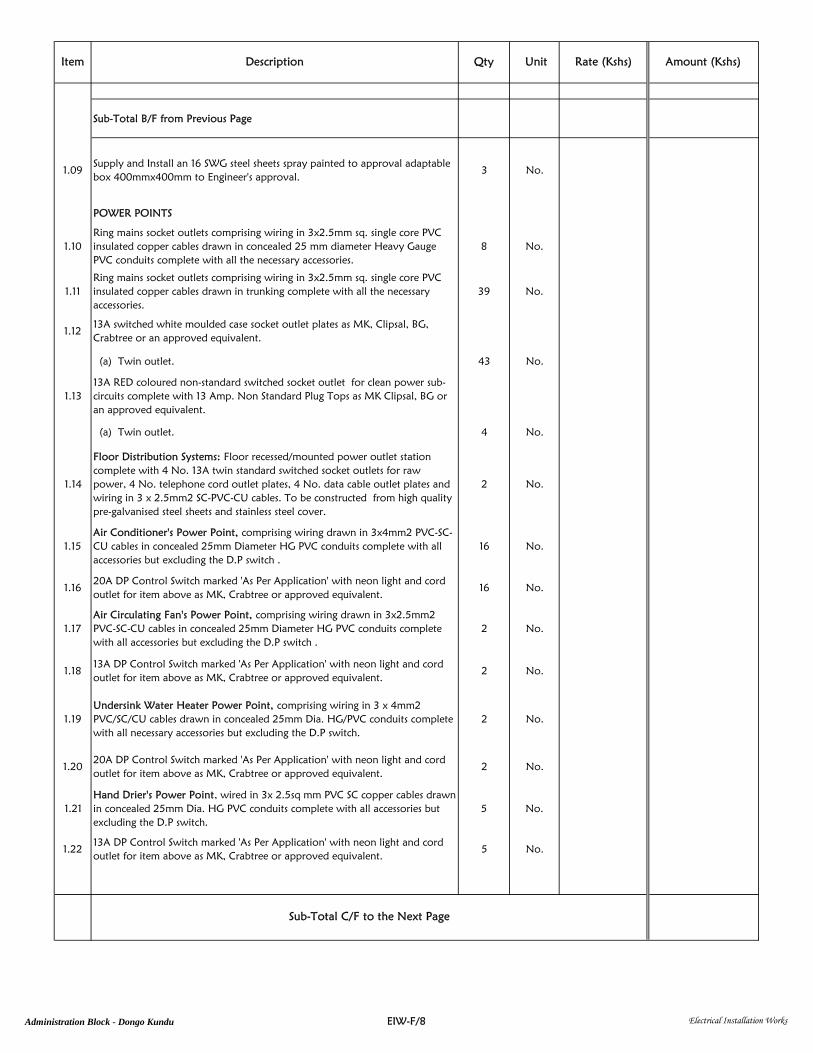
Item Description Qty Unit Rate (Kshs) Amount (Kshs)
Sub-Total B/F from Previous Page
1.09Supply and Install an 16 SWG steel sheets spray painted to approval adaptablebox 400mmx400mm to Engineer's approval.
3 No.
POWER POINTS
1.10Ring mains socket outlets comprising wiring in 3x2.5mm sq. single core PVCinsulated copper cables drawn in concealed 25 mm diameter Heavy GaugePVC conduits complete with all the necessary accessories.
8 No.
1.11Ring mains socket outlets comprising wiring in 3x2.5mm sq. single core PVCinsulated copper cables drawn in trunking complete with all the necessaryaccessories.
39 No.
1.1213A switched white moulded case socket outlet plates as MK, Clipsal, BG,Crabtree or an approved equivalent.
(a) Twin outlet. 43 No.
1.1313A RED coloured non-standard switched socket outlet for clean power sub-circuits complete with 13 Amp. Non Standard Plug Tops as MK Clipsal, BG oran approved equivalent.
(a) Twin outlet. 4 No.
1.14
Floor Distribution Systems: Floor recessed/mounted power outlet stationcomplete with 4 No. 13A twin standard switched socket outlets for rawpower, 4 No. telephone cord outlet plates, 4 No. data cable outlet plates andwiring in 3 x 2.5mm2 SC-PVC-CU cables. To be constructed from high qualitypre-galvanised steel sheets and stainless steel cover.
2 No.
1.15Air Conditioner's Power Point, comprising wiring drawn in 3x4mm2 PVC-SC-CU cables in concealed 25mm Diameter HG PVC conduits complete with allaccessories but excluding the D.P switch .
16 No.
1.1620A DP Control Switch marked 'As Per Application' with neon light and cordoutlet for item above as MK, Crabtree or approved equivalent.
16 No.
1.17Air Circulating Fan's Power Point, comprising wiring drawn in 3x2.5mm2PVC-SC-CU cables in concealed 25mm Diameter HG PVC conduits completewith all accessories but excluding the D.P switch .
2 No.
1.1813A DP Control Switch marked 'As Per Application' with neon light and cordoutlet for item above as MK, Crabtree or approved equivalent.
2 No.
1.19Undersink Water Heater Power Point, comprising wiring in 3 x 4mm2PVC/SC/CU cables drawn in concealed 25mm Dia. HG/PVC conduits completewith all necessary accessories but excluding the D.P switch.
2 No.
1.2020A DP Control Switch marked 'As Per Application' with neon light and cordoutlet for item above as MK, Crabtree or approved equivalent.
2 No.
1.21Hand Drier's Power Point, wired in 3x 2.5sq mm PVC SC copper cables drawnin concealed 25mm Dia. HG PVC conduits complete with all accessories butexcluding the D.P switch.
5 No.
1.2213A DP Control Switch marked 'As Per Application' with neon light and cordoutlet for item above as MK, Crabtree or approved equivalent.
5 No.
Sub-Total C/F to the Next Page
EIW-F/8 Electrical Installation WorksAdministration Block - Dongo Kundu

Item Description Qty Unit Rate (Kshs) Amount (Kshs)
Sub-Total B/F from Previous Page
1.23Toilet Extract Fan (1-Φ) Power Point, wired in 3x 2.5sq mm PVC SC coppercables drawn in concealed 25mm Dia. HG PVC conduits complete with allaccessories but excluding the D.P switch.
5 No.
1.2413A DP Control Switch marked 'As Per Application' with neon light and cordoutlet for item above as MK, Crabtree or approved equivalent.
5 No.
1.25Cooker (1-Φ) Power Point, comprising of 3x6mm2 PVC SC Copper cablesdrawn in concealed 25mm Dia. HG PVC conduits complete with allaccessories.
2 No.
1.2645A DP Cooker Control Unit with 13A integral Socket Outlet and Pilot Lampmarked 'As Per Application' for item above as MK, MEM or approvedequivalent.
2 No.
1.27Cooker Connection Unit for flush mounting and wired from Cooker ControlUnit.
2 No.
1.28 TELEVISION POINTS
a) TV outlet point wired in 75 Ohms Screened Coaxial TV cables drawn inconcealed 20mm diameter HG/PVC conduits and linked to the outside throughthe roof space (to the amplifier) via telephone draw in boxes.
3 No.
b) TV outlet plate with polished brass finish as MK, Clipsal, Crabtree orapproved equivalent.
3 No
c) 300mmx250mmx150mm, 18SWG, powder coated, telephone draw boxspray painted to approval.
1 No
DATA&TELEPHONE POINTS
1.29Data/Telephone outlet point done in 25mm Dia. HG PVC conduits concealedin building fabric/ trunking complete with all necessary accessories.
23 No.
CCTV & ACCESS CONTROL POINTS
1.30
CCTV & Access Control System Points done in 25mm Dia. HG PVC conduitsconcealed in building fabric/trunking complete with all necessary accessories(N/B: conduit length for each point running from the communication room isapproximately 20m).
19 No.
INTERNAL POWER DISTRIBUTION
1.318Ways TPN+E, flush mounted Distribution Board complete with 100A integralisolator as SCHNEIDER ELECTRIC, HAUSMANN or an approved equivalentcomplete with all accessories but excluding MCBs.
3 No.
1.32 MCB’s for item above
(i) 10A SP 12 No.
(ii) 20A SP 30 No.
(iii) 32A SP 9 No.
Sub-Total C/F to the Next Page
EIW-F/9 Electrical Installation WorksAdministration Block - Dongo Kundu

Item Description Qty Unit Rate (Kshs) Amount (Kshs)
Sub-Total B/F from Previous Page
(iv) 45A SP 2 No.
(v) SP Spareway 7 No.
(vi) TP Spareway 4 No.
1.33Carry out concise permanent traffolyte labelling for all the sub-circuits in itemabove.
3 Item
SUB-MAIN POWER DISTRIBUTION CABLE
1.3425mm2 4Core PVC/SWA/PVC Copper cables in 50mmØ concealed HG PVCconduits complete with appropriate cable glands and any other necessaryaccessory
80 Lm.
1.35 FIRE DETECTION AND ALARM SYSTEM
Supply, deliver, install and commission a complete Fire Detection and Alarmsystem, addressable type and in accordance with BS 5839 :2000, P2 and L2
i) Outlet for Fire Alarm Panel's concealed 25mm HG PVC conduit, wiring in 3x 2.5mm2 SC-PVC-CU fire rated cables and all accessories, including 5A fusedunswitched connection unit with neon light.
1 No.
ii) Outlet for fire alarm manual call point/smoke/heat detector comprising box,concealed 20mm HG PVC conduit, wiring in 3 x 1.5mm2 fire rated cables andall accessories.
36 No.
iii) Addressable Manual Fire break glass call point unit as MENVIER orapproved equivalent complete with a packet of 5 spare glasses, a packet of 5spare test keys, a spare back box and a hinged cover to be installed recessed inbuilding fabric.
4 No.
iv) Addressable Electronic Fire Alarm Sounder complete with Red FlashingBeacon Light as MENVIER or approved equivalent.
4 No.
v) Addressable Photometric Smoke Detector as Menvier MENVIER or equaland approved.
26 No.
vi) Addressable Rate of Heat Rise Detector as Menvier MENVIER or equal andapproved.
2 No.
vii) 12 - Loop zone addressable fire alarm control panel complete with 72hrsautonomous time emergency batteries as Menvier DF6100 or equal andapproved.
1 No.
Total for Schedule No. 1: Ground Floor C/F to Price Summary Page
EIW-F/10 Electrical Installation WorksAdministration Block - Dongo Kundu

Item Description Qty Unit Rate (Kshs) Amount (Kshs)
Supply, Install, test and commission the following :
2.01Lighting points comprising wiring in 3x1.5mm2 Single Core PVC insulatedCopper Cables drawn in concealed 20mm Diameter HG PVC conduitscomplete with all necessary accessories but excluding switches for:-
(a) One Way Switching. 118 No.
(b) Two Way Switching. 47 No.
(c) Unswitched. 5 No.
2.0210A moulded ivory switch plates as MK, BG, Crabtree or approved equivalentas follows:
(a) 1 gang 1 way 36 No.
(b) 2 gang 1 way 1 No.
(c) 2 gang 2 way 16 No.
(d) 3 gang 1 way 5 No.
(e) Intermediate Switch 2 No.
LIGHTING FITTINGS
2.03Lighting fittings complete with all accessories including LED tubes & lamps ofappropriate wattage and colour rendering and fixing materials as follows:
(a) 600mm by 600mm, 4x18W, modular surface/recessed fluorescentluminaire designed for use in lay-in ceiling grids, with louvre retention system,electronic ballast and plug and socket installation method.
44 No.
(b) 37W, 600mm x 600mm, LED Panel Lighting fitting as Philips FullGlow orapproved equivalent.
4 No.
(c) 10.5W slim LED downlighter as Philips GreenLED Ultima or approvedequivalent.
24 No.
(d) Recessed downlight mains single 18W LED lamp, with daylight output, satinfinish, with specular anodised aluminium reflector and silver effect as ThornChalice 190 Recessed or approved equivalent.
20 No.
(e) Compact and flexible LED Strip Light, with warm white output, with selfadhesive tape on the reverse for fast installation, IP20 rating, upto 60 LED/Mfor high lighting homogenity as Thorn ArrowFlex or approved equivalent.
40 Lm
(f) 1200mm, 1x36W standard waterproof IP65 fluorescent fitting with injectionmoulded polycarbonae body and polycarbonanate diffuser for T8 lamp withelectronic control gear as Thorn Aquaproof or an approved equivalent.
4 No.
(g) Standard, Shallow surface luminaire with circular opal diffuser and whitestand-off ring, with integral HPF control gear for 16W 2D compact fluorescentlamp. As Thorn Glorie or approved equivalent.
14 No.
SCHEDULE NO. 2: FIRST FLOOR
Sub-Total C/F to the Next Page
EIW-F/11 Electrical Installation WorksAdministration Block - Dongo Kundu

Item Description Qty Unit Rate (Kshs) Amount (Kshs)
Sub-Total B/F from Previous Page
(h) 1200mm, 1x36W HPF, Surface Mounted Fluorescent batten fitting of slimcross section with electronic control gear, clip-on cover plate and adjustableend cap system as Thorn Popular Pack Batten or equal and approvedequivalent.
2 No.
(i) Standard circular splashproof surface luminaire with polycarbonate bodyand white trim, polycarbonate opal diffuser and integral control gear for 28 W2D compact flourescent lamp as THORN Superclub or approved equivalent.
29 No.
(j) 1200mm, 1x 36 Watts slim fluorescent fitting with prismatic diffuser withouta socket outlet point, for mirror lighting, as EGLO or approved equivalent.
12 No.
(k) 40W Outdoor Bulkhead with Opal Diffuser, grill & visor, IP65 protectionas Massive Cleveland Outdoor or an approved equivalent.
11 No.
(l) Self-contained double sided EXIT sign with 8W fluorescent lamp for non-maintained emergency lighting for 3 hour duration as Sapphire or approvedequivalent.
5 No.
2.04 TRUNKING & DUCTING
i) 200x50mm two (2) compartment powder coated trunking manufactured in14 swg galvanized mild steel sheet and finished in cream powder coating todetails shown complete with covers and all fixing accessories. Allow for colourchange to Architect’s detail.
200 Lm.
ii) Factory made powder coated corner bends for the above trunking. 30 No.
iii) Powder coated twin punched outlet plate for fixing twin socket outlets. 55 No.
iv) Ditto but for data/telephone/single switched socket outlets. 24 No.
v) Carry out bonding throughout the entire length of the above trunking andconnect to earthing.
1 Item
2.05200mm x 50mm deep perfotrated GI cable tray complete with all accessoriesinside ceiling as manufactured by Schneider Electric Kenya or an approvedequivalent.
30 Lm.
2.06Lay HG/PVC conduiting of size 3x32mm diameter HG/PVC ducts from theelectrical service duct to the metal trunkings for telecommunication services.
40 Lm.
2.07Lay HG/PVC conduiting of size 3x50mm diameter HG/PVC ducts from theelectrical service duct to the metal trunkings for internal power reticulation.
40 Lm.
2.08Lay HG/PVC conduiting of size 2x100mm diameter HG/PVC ducts inter-connecting electrical service ducts.
70 Lm.
2.09Supply and Install an 16 SWG steel sheets spray painted to approval adaptablebox 400mmx400mm to Engineer's approval.
3 No.
POWER POINTS
2.10Ring mains socket outlets comprising wiring in 3x2.5mm sq. single core PVCinsulated copper cables drawn in concealed 25 mm diameter Heavy GaugePVC conduits complete with all the necessary accessories.
7 No.
Sub-Total C/F to the Next Page
EIW-F/12 Electrical Installation WorksAdministration Block - Dongo Kundu

Item Description Qty Unit Rate (Kshs) Amount (Kshs)
Sub-Total B/F from Previous Page
2.11Ring mains socket outlets comprising wiring in 3x2.5mm sq. single core PVCinsulated copper cables drawn in trunking complete with all the necessaryaccessories.
55 No.
2.1213A switched white moulded case socket outlet plates as MK, Clipsal, BG,Crabtree or an approved equivalent.
(a) Twin outlet. 62 No.
2.13Air Conditioner's Power Point, comprising wiring drawn in 3x4mm2 PVC-SC-CU cables in concealed 25mm Diameter HG PVC conduits complete with allaccessories but excluding the D.P switch .
24 No.
2.1420A DP Control Switch marked 'As Per Application' with neon light and cordoutlet for item above as MK, Crabtree or approved equivalent.
24 No.
2.15Air Circulating Fan's Power Point, comprising wiring drawn in 3x2.5mm2PVC-SC-CU cables in concealed 25mm Diameter HG PVC conduits completewith all accessories but excluding the D.P switch .
2 No.
2.1613A DP Control Switch marked 'As Per Application' with neon light and cordoutlet for item above as MK, Crabtree or approved equivalent.
2 No.
2.17Undersink Water Heater Power Point, comprising wiring in 3 x 4mm2PVC/SC/CU cables drawn in concealed 25mm Dia. HG/PVC conduits completewith all necessary accessories but excluding the D.P switch.
2 No.
2.1820A DP Control Switch marked 'As Per Application' with neon light and cordoutlet for item above as MK, Crabtree or approved equivalent.
2 No.
2.19Hand Drier's Power Point, wired in 3x 2.5sq mm PVC SC copper cables drawnin concealed 25mm Dia. HG PVC conduits complete with all accessories butexcluding the D.P switch.
5 No.
2.2013A DP Control Switch marked 'As Per Application' with neon light and cordoutlet for item above as MK, Crabtree or approved equivalent.
5 No.
2.21Toilet Extract Fan (1-Φ) Power Point, wired in 3x 2.5sq mm PVC SC coppercables drawn in concealed 25mm Dia. HG PVC conduits complete with allaccessories but excluding the D.P switch.
5 No.
2.2213A DP Control Switch marked 'As Per Application' with neon light and cordoutlet for item above as MK, Crabtree or approved equivalent.
5 No.
2.23Cooker (1-Φ) Power Point, comprising of 3x6mm2 PVC SC Copper cablesdrawn in concealed 25mm Dia. HG PVC conduits complete with allaccessories.
2 No.
2.2445A DP Cooker Control Unit with 13A integral Socket Outlet and Pilot Lampmarked 'As Per Application' for item above as MK, MEM or approvedequivalent.
2 No.
2.25Cooker Connection Unit for flush mounting and wired from Cooker ControlUnit.
2 No.
2.26 TELEVISION POINTS
a) TV outlet point wired in 75 Ohms Screened Coaxial TV cables drawn inconcealed 20mm diameter HG/PVC conduits and linked to the outside throughthe roof space (to the amplifier) via telephone draw in boxes.
1 No.
Sub-Total C/F to the Next Page
EIW-F/13 Electrical Installation WorksAdministration Block - Dongo Kundu

Item Description Qty Unit Rate (Kshs) Amount (Kshs)
Sub-Total B/F from Previous Page
b) TV outlet plate with polished brass finish as MK, Clipsal, Crabtree orapproved equivalent.
1 No
c) 300mmx250mmx150mm, 18SWG, powder coated, telephone draw boxspray painted to approval.
1 No
DATA&TELEPHONE POINTS
2.27Data/Telephone outlet point done in 25mm Dia. HG PVC conduits concealedin building fabric/ trunking complete with all necessary accessories.
24 No.
CCTV & ACCESS CONTROL POINTS
2.28
CCTV & Access Control System Points done in 25mm Dia. HG PVC conduitsconcealed in building fabric/trunking complete with all necessary accessories(N/B: conduit length for each point running from the communication room isapproximately 20m).
10 No.
INTERNAL POWER DISTRIBUTION
2.298Ways TPN+E, flush mounted Distribution Board complete with 100A integralisolator as SCHNEIDER ELECTRIC, HAUSMANN or an approved equivalentcomplete with all accessories but excluding MCBs.
3 No.
2.30 MCB’s for item above
(i) 10A SP 12 No.
(ii) 20A SP 38 No.
(iii) 32A SP 11 No.
(iv) 45A SP 2 No.
(v) SP Spareway 3 No.
(vi) TP Spareway 2 No.
2.31Carry out concise permanent traffolyte labelling for all the sub-circuits in itemabove.
3 Item
SUB-MAIN POWER DISTRIBUTION CABLE
2.3225mm2 4Core PVC/SWA/PVC Copper cables in 50mmØ concealed HG PVCconduits complete with appropriate cable glands and any other necessaryaccessory
100 Lm.
Sub-Total C/F to the Next Page
EIW-F/14 Electrical Installation WorksAdministration Block - Dongo Kundu

Item Description Qty Unit Rate (Kshs) Amount (Kshs)
Sub-Total B/F from Previous Page
2.33 FIRE DETECTION AND ALARM SYSTEM
Supply, deliver, install and commission a complete Fire Detection and Alarmsystem, addressable type and in accordance with BS 5839 :2000, P2 and L2
i) Outlet for Fire Alarm Panel's concealed 25mm HG PVC conduit, wiring in 3x 2.5mm2 SC-PVC-CU fire rated cables and all accessories, including 5A fusedunswitched connection unit with neon light.
1 No.
ii) Outlet for fire alarm manual call point/smoke/heat detector comprising box,concealed 20mm HG PVC conduit, wiring in 3 x 1.5mm2 fire rated cables andall accessories.
48 No.
iii) Addressable Manual Fire break glass call point unit as MENVIER orapproved equivalent complete with a packet of 5 spare glasses, a packet of 5spare test keys, a spare back box and a hinged cover to be installed recessed inbuilding fabric.
4 No.
iv) Addressable Electronic Fire Alarm Sounder complete with Red FlashingBeacon Light as MENVIER or approved equivalent.
4 No.
v) Addressable Photometric Smoke Detector as Menvier MENVIER or equaland approved.
38 No.
vi) Addressable Rate of Heat Rise Detector as Menvier MENVIER or equal andapproved.
2 No.
vii) Addressable fire alarm repeater panel Menvier DF6100 or equal andapproved.
1 No.
Total for Schedule No. 2: First Floor C/F to Price Summary Page
EIW-F/15 Electrical Installation WorksAdministration Block - Dongo Kundu

Item Description Qty Unit Rate (Kshs) Amount (Kshs)
Supply, Install, test and commission the following :
3.01Lighting points comprising wiring in 3x1.5mm2 Single Core PVC insulatedCopper Cables drawn in concealed 20mm Diameter HG PVC conduitscomplete with all necessary accessories but excluding switches for:-
(a) One Way Switching. 96 No.
(b) Two Way Switching. 61 No.
(c) Unswitched. 5 No.
3.0210A moulded ivory switch plates as MK, BG, Crabtree or approved equivalentas follows:
(a) 1 gang 1 way 25 No.
(b) 1 gang 2 way 10 No.
(c) 2 gang 1 way 1 No.
(d) 2 gang 2 way 4 No.
(e) 3 gang 1 way 4 No.
(f) 3 gang 2 way 2 No.
(g) Intermediate Switch 2 No.
LIGHTING FITTINGS
3.03Lighting fittings complete with all accessories including LED tubes & lamps ofappropriate wattage and colour rendering and fixing materials as follows:
(a) 600mm by 600mm, 4x18W, modular surface/recessed fluorescentluminaire designed for use in lay-in ceiling grids, with louvre retention system,electronic ballast and plug and socket installation method.
40 No.
(b) 37W, 600mm x 600mm, LED Panel Lighting fitting as Philips FullGlow orapproved equivalent.
8 No.
(c) 10.5W slim LED downlighter as Philips GreenLED Ultima or approvedequivalent.
22 No.
(d) Recessed downlight mains single 18W LED lamp, with daylight output, satinfinish, with specular anodised aluminium reflector and silver effect as ThornChalice 190 Recessed or approved equivalent.
20 No.
(e) Compact and flexible LED Strip Light, with warm white output, with selfadhesive tape on the reverse for fast installation, IP20 rating, upto 60 LED/Mfor high lighting homogenity as Thorn ArrowFlex or approved equivalent.
40 Lm
(f) 1200mm, 1x36W standard waterproof IP65 fluorescent fitting with injectionmoulded polycarbonae body and polycarbonanate diffuser for T8 lamp withelectronic control gear as Thorn Aquaproof or an approved equivalent.
4 No.
(g) 1200mm, 1x36W HPF, Surface Mounted Fluorescent batten fitting of slimcross section with electronic control gear, clip-on cover plate and adjustableend cap system as Thorn Popular Pack Batten or equal and approvedequivalent.
2 No.
SCHEDULE NO. 3: SECOND FLOOR
Sub-Total C/F to the Next Page
EIW-F/16 Electrical Installation WorksAdministration Block - Dongo Kundu

Item Description Qty Unit Rate (Kshs) Amount (Kshs)
Sub-Total B/F from Previous Page
(h) Standard circular splashproof surface luminaire with polycarbonate bodyand white trim, polycarbonate opal diffuser and integral control gear for 28 W2D compact flourescent lamp as THORN Superclub or approved equivalent.
29 No.
(i) 1200mm, 1x 36 Watts slim fluorescent fitting with prismatic diffuser withouta socket outlet point, for mirror lighting, as EGLO or approved equivalent.
10 No.
(j) 40W Outdoor Bulkhead with Opal Diffuser, grill & visor, IP65 protection asMassive Cleveland Outdoor or an approved equivalent.
11 No.
(k) Standard, Shallow surface luminaire with circular opal diffuser and whitestand-off ring, with integral HPF control gear for 16W 2D compact fluorescentlamp. As Thorn Glorie or approved equivalent.
10 No.
(l) Self-contained double sided EXIT sign with 8W fluorescent lamp for non-maintained emergency lighting for 3 hour duration as Sapphire or approvedequivalent.
5 No.
3.04 TRUNKING & DUCTING
i) 200x50mm two (2) compartment powder coated trunking manufactured in14 swg galvanized mild steel sheet and finished in cream powder coating todetails shown complete with covers and all fixing accessories. Allow for colourchange to Architect’s detail.
200 Lm.
ii) Factory made powder coated corner bends for the above trunking. 28 No.
iii) Powder coated twin punched outlet plate for fixing twin socket outlets. 50 No.
iv) Ditto but for data/telephone/single switched socket outlets. 24 No.
v) Carry out bonding throughout the entire length of the above trunking andconnect to earthing.
1 Item
3.05200mm x 50mm deep perfotrated GI cable tray complete with all accessoriesinside ceiling as manufactured by Schneider Electric Kenya or an approvedequivalent.
30 Lm.
3.06Lay HG/PVC conduiting of size 3x32mm diameter HG/PVC ducts from theelectrical service duct to the metal trunkings for telecommunication services.
40 Lm.
3.07Lay HG/PVC conduiting of size 3x50mm diameter HG/PVC ducts from theelectrical service duct to the metal trunkings for internal power reticulation.
40 Lm.
3.08Lay HG/PVC conduiting of size 2x100mm diameter HG/PVC ducts inter-connecting electrical service ducts.
70 Lm.
3.09Supply and Install an 16 SWG steel sheets spray painted to approval adaptablebox 400mmx400mm to Engineer's approval.
3 No.
POWER POINTS
3.10Ring mains socket outlets comprising wiring in 3x2.5mm sq. single core PVCinsulated copper cables drawn in concealed 25 mm diameter Heavy GaugePVC conduits complete with all the necessary accessories.
6 No.
Sub-Total C/F to the Next Page
EIW-F/17 Electrical Installation WorksAdministration Block - Dongo Kundu

Item Description Qty Unit Rate (Kshs) Amount (Kshs)
Sub-Total B/F from Previous Page
3.11Ring mains socket outlets comprising wiring in 3x2.5mm sq. single core PVCinsulated copper cables drawn in trunking complete with all the necessaryaccessories.
50 No.
3.1213A switched white moulded case socket outlet plates as MK, Clipsal, BG,Crabtree or an approved equivalent.
(a) Twin outlet. 56 No.
3.13Air Conditioner's Power Point, comprising wiring drawn in 3x4mm2 PVC-SC-CU cables in concealed 25mm Diameter HG PVC conduits complete with allaccessories but excluding the D.P switch .
24 No.
3.1420A DP Control Switch marked 'As Per Application' with neon light and cordoutlet for item above as MK, Crabtree or approved equivalent.
24 No.
3.15Air Circulating Fan's Power Point, comprising wiring drawn in 3x2.5mm2PVC-SC-CU cables in concealed 25mm Diameter HG PVC conduits completewith all accessories but excluding the D.P switch .
2 No.
3.1613A DP Control Switch marked 'As Per Application' with neon light and cordoutlet for item above as MK, Crabtree or approved equivalent.
2 No.
3.17Undersink Water Heater Power Point, comprising wiring in 3 x 4mm2PVC/SC/CU cables drawn in concealed 25mm Dia. HG/PVC conduits completewith all necessary accessories but excluding the D.P switch.
2 No.
3.1820A DP Control Switch marked 'As Per Application' with neon light and cordoutlet for item above as MK, Crabtree or approved equivalent.
2 No.
3.19Hand Drier's Power Point, wired in 3x 2.5sq mm PVC SC copper cables drawnin concealed 25mm Dia. HG PVC conduits complete with all accessories butexcluding the D.P switch.
5 No.
3.2013A DP Control Switch marked 'As Per Application' with neon light and cordoutlet for item above as MK, Crabtree or approved equivalent.
5 No.
3.21Toilet Extract Fan (1-Φ) Power Point, wired in 3x 2.5sq mm PVC SC coppercables drawn in concealed 25mm Dia. HG PVC conduits complete with allaccessories but excluding the D.P switch.
5 No.
3.2213A DP Control Switch marked 'As Per Application' with neon light and cordoutlet for item above as MK, Crabtree or approved equivalent.
5 No.
3.23Cooker (1-Φ) Power Point, comprising of 3x6mm2 PVC SC Copper cablesdrawn in concealed 25mm Dia. HG PVC conduits complete with allaccessories.
2 No.
3.2445A DP Cooker Control Unit with 13A integral Socket Outlet and Pilot Lampmarked 'As Per Application' for item above as MK, MEM or approvedequivalent.
2 No.
3.25Cooker Connection Unit for flush mounting and wired from Cooker ControlUnit.
2 No.
3.26 TELEVISION POINTS
a) TV outlet point wired in 75 Ohms Screened Coaxial TV cables drawn inconcealed 20mm diameter HG/PVC conduits and linked to the outside throughthe roof space (to the amplifier) via telephone draw in boxes.
6 No.
Sub-Total C/F to the Next Page
EIW-F/18 Electrical Installation WorksAdministration Block - Dongo Kundu

Item Description Qty Unit Rate (Kshs) Amount (Kshs)
Sub-Total B/F from Previous Page
b) TV outlet plate with polished brass finish as MK, Clipsal, Crabtree orapproved equivalent.
6 No
c) 300mmx250mmx150mm, 18SWG, powder coated, telephone draw boxspray painted to approval.
2 No
DATA&TELEPHONE POINTS
3.27Data/Telephone outlet point done in 25mm Dia. HG PVC conduits concealedin building fabric/ trunking complete with all necessary accessories.
24 No.
CCTV & ACCESS CONTROL POINTS
3.28
CCTV & Access Control System Points done in 25mm Dia. HG PVC conduitsconcealed in building fabric/trunking complete with all necessary accessories(N/B: conduit length for each point running from the communication room isapproximately 20m).
12 No.
INTERNAL POWER DISTRIBUTION
3.298Ways TPN+E, flush mounted Distribution Board complete with 100A integralisolator as SCHNEIDER ELECTRIC, HAUSMANN or an approved equivalentcomplete with all accessories but excluding MCBs.
3 No.
3.30 MCB’s for item above
(i) 10A SP 12 No.
(ii) 20A SP 38 No.
(iii) 32A SP 11 No.
(iv) 45A SP 2 No.
(v) SP Spareway 3 No.
(vi) TP Spareway 2 No.
3.31Carry out concise permanent traffolyte labelling for all the sub-circuits in itemabove.
3 Item
SUB-MAIN POWER DISTRIBUTION CABLE
3.3225mm2 4Core PVC/SWA/PVC Copper cables in 50mmØ concealed HG PVCconduits complete with appropriate cable glands and any other necessaryaccessory
120 Lm.
Sub-Total C/F to the Next Page
EIW-F/19 Electrical Installation WorksAdministration Block - Dongo Kundu

Item Description Qty Unit Rate (Kshs) Amount (Kshs)
Sub-Total B/F from Previous Page
3.33 FIRE DETECTION AND ALARM SYSTEM
Supply, deliver, install and commission a complete Fire Detection and Alarmsystem, addressable type and in accordance with BS 5839 :2000, P2 and L2
i) Outlet for Fire Alarm Panel's concealed 25mm HG PVC conduit, wiring in 3x 2.5mm2 SC-PVC-CU fire rated cables and all accessories, including 5A fusedunswitched connection unit with neon light.
1 No.
ii) Outlet for fire alarm manual call point/smoke/heat detector comprising box,concealed 20mm HG PVC conduit, wiring in 3 x 1.5mm2 fire rated cables andall accessories.
48 No.
iii) Addressable Manual Fire break glass call point unit as MENVIER orapproved equivalent complete with a packet of 5 spare glasses, a packet of 5spare test keys, a spare back box and a hinged cover to be installed recessed inbuilding fabric.
4 No.
iv) Addressable Electronic Fire Alarm Sounder complete with Red FlashingBeacon Light as MENVIER or approved equivalent.
4 No.
v) Addressable Photometric Smoke Detector as Menvier MENVIER or equaland approved.
38 No.
vi) Addressable Rate of Heat Rise Detector as Menvier MENVIER or equal andapproved.
2 No.
vii) Addressable fire alarm repeater panel Menvier DF6100 or equal andapproved.
1 No.
Total for Schedule No. 3: Second Floor C/F to Price Summary Page
EIW-F/20 Electrical Installation WorksAdministration Block - Dongo Kundu

Item Description Qty Unit Rate (Kshs) Amount (Kshs)
Supply, Install, test and commission the following :
4.01Lighting points comprising wiring in 3x1.5mm2 Single Core PVC insulatedCopper Cables drawn in concealed 20mm Diameter HG PVC conduitscomplete with all necessary accessories but excluding switches for:-
(a) One Way Switching. 61 No.
(b) Two Way Switching. 64 No.
(c) Unswitched. 5 No.
4.0210A moulded ivory switch plates as MK, BG, Crabtree or approved equivalentas follows:
(a) 1 gang 1 way 23 No.
(b) 2 gang 1 way 4 No.
(c) 2 gang 2 way 14 No.
(d) 3 gang 1 way 2 No.
(e) 3 gang 2 way 2 No.
(f) Intermediate Switch 2 No.
LIGHTING FITTINGS
4.03Lighting fittings complete with all accessories including LED tubes & lamps ofappropriate wattage and colour rendering and fixing materials as follows:
(a) 600mm by 600mm, 4x18W, modular surface/recessed fluorescentluminaire designed for use in lay-in ceiling grids, with louvre retention system,electronic ballast and plug and socket installation method.
12 No.
(b) 37W, 600mm x 600mm, LED Panel Lighting fitting as Philips FullGlow orapproved equivalent.
8 No.
(c) 10.5W slim LED downlighter as Philips GreenLED Ultima or approvedequivalent.
27 No.
(d) Recessed downlight mains single 18W LED lamp, with daylight output, satinfinish, with specular anodised aluminium reflector and silver effect as ThornChalice 190 Recessed or approved equivalent.
20 No.
(e) Compact and flexible LED Strip Light, with warm white output, with selfadhesive tape on the reverse for fast installation, IP20 rating, upto 60 LED/Mfor high lighting homogenity as Thorn ArrowFlex or approved equivalent.
40 Lm
(f) 1200mm, 1x36W standard waterproof IP65 fluorescent fitting with injectionmoulded polycarbonae body and polycarbonanate diffuser for T8 lamp withelectronic control gear as Thorn Aquaproof or an approved equivalent.
2 No.
(g) 1200mm, 1x36W HPF, Surface Mounted Fluorescent batten fitting of slimcross section with electronic control gear, clip-on cover plate and adjustableend cap system as Thorn Popular Pack Batten or equal and approvedequivalent.
2 No.
SCHEDULE NO. 4: THIRD FLOOR
Sub-Total C/F to the Next Page
EIW-F/21 Electrical Installation WorksAdministration Block - Dongo Kundu

Item Description Qty Unit Rate (Kshs) Amount (Kshs)
Sub-Total B/F from Previous Page
(h) Standard circular splashproof surface luminaire with polycarbonate bodyand white trim, polycarbonate opal diffuser and integral control gear for 28 W2D compact flourescent lamp as THORN Superclub or approved equivalent.
20 No.
(i) 1200mm, 1x 36 Watts slim fluorescent fitting with prismatic diffuser withouta socket outlet point, for mirror lighting, as EGLO or approved equivalent.
8 No.
(j) 40W Outdoor Bulkhead with Opal Diffuser, grill & visor, IP65 protection asMassive Cleveland Outdoor or an approved equivalent.
15 No.
(k) Standard, Shallow surface luminaire with circular opal diffuser and whitestand-off ring, with integral HPF control gear for 16W 2D compact fluorescentlamp. As Thorn Glorie or approved equivalent.
10 No.
(l) Self-contained double sided EXIT sign with 8W fluorescent lamp for non-maintained emergency lighting for 3 hour duration as Sapphire or approvedequivalent.
5 No.
4.04 TRUNKING & DUCTING
i) 200x50mm two (2) compartment powder coated trunking manufactured in14 swg galvanized mild steel sheet and finished in cream powder coating todetails shown complete with covers and all fixing accessories. Allow for colourchange to Architect’s detail.
142 Lm.
ii) Factory made powder coated corner bends for the above trunking. 13 No.
iii) Powder coated twin punched outlet plate for fixing twin socket outlets. 18 No.
iv) Ditto but for data/telephone/single switched socket outlets. 18 No.
v) Carry out bonding throughout the entire length of the above trunking andconnect to earthing.
1 Item
4.05200mm x 50mm deep perfotrated GI cable tray complete with all accessoriesinside ceiling as manufactured by Schneider Electric Kenya or an approvedequivalent.
30 Lm.
4.06Lay HG/PVC conduiting of size 3x32mm diameter HG/PVC ducts from theelectrical service duct to the metal trunkings for telecommunication services.
40 Lm.
4.07Lay HG/PVC conduiting of size 3x50mm diameter HG/PVC ducts from theelectrical service duct to the metal trunkings for internal power reticulation.
40 Lm.
4.08Lay HG/PVC conduiting of size 2x100mm diameter HG/PVC ducts inter-connecting electrical service ducts.
70 Lm.
4.09Supply and Install an 16 SWG steel sheets spray painted to approval adaptablebox 400mmx400mm to Engineer's approval.
3 No.
POWER POINTS
4.10Ring mains socket outlets comprising wiring in 3x2.5mm sq. single core PVCinsulated copper cables drawn in concealed 25 mm diameter Heavy GaugePVC conduits complete with all the necessary accessories.
6 No.
Sub-Total C/F to the Next Page
EIW-F/22 Electrical Installation WorksAdministration Block - Dongo Kundu

Item Description Qty Unit Rate (Kshs) Amount (Kshs)
Sub-Total B/F from Previous Page
4.11Ring mains socket outlets comprising wiring in 3x2.5mm sq. single core PVCinsulated copper cables drawn in trunking complete with all the necessaryaccessories.
18 No.
4.1213A switched white moulded case socket outlet plates as MK, Clipsal, BG,Crabtree or an approved equivalent.
(a) Twin outlet. 24 No.
4.13Air Conditioner's Power Point, comprising wiring drawn in 3x4mm2 PVC-SC-CU cables in concealed 25mm Diameter HG PVC conduits complete with allaccessories but excluding the D.P switch .
12 No.
4.1420A DP Control Switch marked 'As Per Application' with neon light and cordoutlet for item above as MK, Crabtree or approved equivalent.
12 No.
4.15Air Circulating Fan's Power Point, comprising wiring drawn in 3x2.5mm2PVC-SC-CU cables in concealed 25mm Diameter HG PVC conduits completewith all accessories but excluding the D.P switch .
2 No.
4.1613A DP Control Switch marked 'As Per Application' with neon light and cordoutlet for item above as MK, Crabtree or approved equivalent.
2 No.
4.17Undersink Water Heater Power Point, comprising wiring in 3 x 4mm2PVC/SC/CU cables drawn in concealed 25mm Dia. HG/PVC conduits completewith all necessary accessories but excluding the D.P switch.
1 No.
4.1820A DP Control Switch marked 'As Per Application' with neon light and cordoutlet for item above as MK, Crabtree or approved equivalent.
1 No.
4.19Hand Drier's Power Point, wired in 3x 2.5sq mm PVC SC copper cables drawnin concealed 25mm Dia. HG PVC conduits complete with all accessories butexcluding the D.P switch.
6 No.
4.2013A DP Control Switch marked 'As Per Application' with neon light and cordoutlet for item above as MK, Crabtree or approved equivalent.
6 No.
4.21Toilet Extract Fan (1-Φ) Power Point, wired in 3x 2.5sq mm PVC SC coppercables drawn in concealed 25mm Dia. HG PVC conduits complete with allaccessories but excluding the D.P switch.
6 No.
4.2213A DP Control Switch marked 'As Per Application' with neon light and cordoutlet for item above as MK, Crabtree or approved equivalent.
6 No.
4.23Cooker (1-Φ) Power Point, comprising of 3x6mm2 PVC SC Copper cablesdrawn in concealed 25mm Dia. HG PVC conduits complete with allaccessories.
1 No.
4.2445A DP Cooker Control Unit with 13A integral Socket Outlet and Pilot Lampmarked 'As Per Application' for item above as MK, MEM or approvedequivalent.
1 No.
4.25Cooker Connection Unit for flush mounting and wired from Cooker ControlUnit.
1 No.
4.26 TELEVISION POINTS
a) TV outlet point wired in 75 Ohms Screened Coaxial TV cables drawn inconcealed 20mm diameter HG/PVC conduits and linked to the outside throughthe roof space (to the amplifier) via telephone draw in boxes.
7 No.
Sub-Total C/F to the Next Page
EIW-F/23 Electrical Installation WorksAdministration Block - Dongo Kundu

Item Description Qty Unit Rate (Kshs) Amount (Kshs)
Sub-Total B/F from Previous Page
b) TV outlet plate with polished brass finish as MK, Clipsal, Crabtree orapproved equivalent.
7 No
c) 300mmx250mmx150mm, 18SWG, powder coated, telephone draw boxspray painted to approval.
3 No
DATA&TELEPHONE POINTS
4.27Data/Telephone outlet point done in 25mm Dia. HG PVC conduits concealedin building fabric/ trunking complete with all necessary accessories.
18 No.
CCTV & ACCESS CONTROL POINTS
4.28
CCTV & Access Control System Points done in 25mm Dia. HG PVC conduitsconcealed in building fabric/trunking complete with all necessary accessories(N/B: conduit length for each point running from the communication room isapproximately 20m).
12 No.
INTERNAL POWER DISTRIBUTION
4.298Ways TPN+E, flush mounted Distribution Board complete with 100A integralisolator as SCHNEIDER ELECTRIC, HAUSMANN or an approved equivalentcomplete with all accessories but excluding MCBs.
3 No.
4.30 MCB’s for item above
(i) 10A SP 6 No.
(ii) 20A SP 27 No.
(iii) 32A SP 5 No.
(iv) 45A SP 1 No.
(v) SP Spareway 15 No.
(vi) TP Spareway 6 No.
4.31Carry out concise permanent traffolyte labelling for all the sub-circuits in itemabove.
3 Item
SUB-MAIN POWER DISTRIBUTION CABLE
4.3225mm2 4Core PVC/SWA/PVC Copper cables in 50mmØ concealed HG PVCconduits complete with appropriate cable glands and any other necessaryaccessory
140 Lm.
Sub-Total C/F to the Next Page
EIW-F/24 Electrical Installation WorksAdministration Block - Dongo Kundu

Item Description Qty Unit Rate (Kshs) Amount (Kshs)
Sub-Total B/F from Previous Page
4.33 FIRE DETECTION AND ALARM SYSTEM
Supply, deliver, install and commission a complete Fire Detection and Alarmsystem, addressable type and in accordance with BS 5839 :2000, P2 and L2
i) Outlet for Fire Alarm Panel's concealed 25mm HG PVC conduit, wiring in 3x 2.5mm2 SC-PVC-CU fire rated cables and all accessories, including 5A fusedunswitched connection unit with neon light.
1 No.
ii) Outlet for fire alarm manual call point/smoke/heat detector comprising box,concealed 20mm HG PVC conduit, wiring in 3 x 1.5mm2 fire rated cables andall accessories.
31 No.
iii) Addressable Manual Fire break glass call point unit as MENVIER orapproved equivalent complete with a packet of 5 spare glasses, a packet of 5spare test keys, a spare back box and a hinged cover to be installed recessed inbuilding fabric.
4 No.
iv) Addressable Electronic Fire Alarm Sounder complete with Red FlashingBeacon Light as MENVIER or approved equivalent.
4 No.
v) Addressable Photometric Smoke Detector as Menvier MENVIER or equaland approved.
22 No.
vi) Addressable Rate of Heat Rise Detector as Menvier MENVIER or equal andapproved.
1 No.
vii) Addressable fire alarm repeater panel Menvier DF6100 or equal andapproved.
1 No.
Total for Schedule No. 4: Third Floor C/F to Price Summary Page
EIW-F/25 Electrical Installation WorksAdministration Block - Dongo Kundu

Item Description Qty Unit Rate (Kshs) Amount (Kshs)
Supply, Install, test and commission the following :
5.01Lighting points comprising wiring in 3x1.5mm2 Single Core PVC insulatedCopper Cables drawn in concealed 20mm Diameter HG PVC conduitscomplete with all necessary accessories but excluding switches for:-
(a) One Way Switching. 8 No.
(b) Two Way Switching. 48 No.
(c) Unswitched. 3 No.
5.0210A moulded ivory switch plates as MK, BG, Crabtree or approved equivalentas follows:
(a) 1 gang 1 way 10 No.
(b) 2 gang 2 way 6 No.
LIGHTING FITTINGS
5.03Lighting fittings complete with all accessories including LED tubes & lamps ofappropriate wattage and colour rendering and fixing materials as follows:
(a) 1200mm, 1x36W HPF, Surface Mounted Fluorescent batten fitting of slimcross section with electronic control gear, clip-on cover plate and adjustableend cap system as Thorn Popular Pack Batten or equal and approvedequivalent.
1 No.
(b) 10.5W slim LED downlighter as Philips GreenLED Ultima or approvedequivalent.
20 No.
(c) Recessed downlight mains single 18W LED lamp, with daylight output, satinfinish, with specular anodised aluminium reflector and silver effect as ThornChalice 190 Recessed or approved equivalent.
20 No.
(d) Compact and flexible LED Strip Light, with warm white output, with selfadhesive tape on the reverse for fast installation, IP20 rating, upto 60 LED/Mfor high lighting homogenity as Thorn ArrowFlex or approved equivalent.
40 Lm
(e) 40W Outdoor Bulkhead with Opal Diffuser, grill & visor, IP65 protectionas Massive Cleveland Outdoor or an approved equivalent.
10 No.
(f) Standard, Shallow surface luminaire with circular opal diffuser and whitestand-off ring, with integral HPF control gear for 16W 2D compact fluorescentlamp. As Thorn Glorie or approved equivalent.
4 No.
(g) Self-contained double sided EXIT sign with 8W fluorescent lamp for non-maintained emergency lighting for 3 hour duration as Sapphire or approvedequivalent.
3 No.
DUCTING
5.04Lay HG/PVC conduiting of size 2x100mm diameter HG/PVC ducts inter-connecting electrical service ducts.
50 Lm.
SCHEDULE NO. 5: FOURTH FLOOR
Sub-Total C/F to the Next Page
EIW-F/26 Electrical Installation WorksAdministration Block - Dongo Kundu

Item Description Qty Unit Rate (Kshs) Amount (Kshs)
Sub-Total B/F from Previous Page
5.05Supply and Install an 16 SWG steel sheets spray painted to approval adaptablebox 400mmx400mm to Engineer's approval.
2 No.
POWER POINTS
5.06Ring mains socket outlets comprising wiring in 3x2.5mm sq. single core PVCinsulated copper cables drawn in concealed 25 mm diameter Heavy GaugePVC conduits complete with all the necessary accessories.
9 No.
5.0713A switched white moulded case socket outlet plates as MK, Clipsal, BG,Crabtree or an approved equivalent.
(a) Twin outlet. 9 No.
5.08AC Outdoor Unit's Power Point, comprising wiring drawn in 5x10mm2 PVC-SC-CU cables in concealed 50mm Diameter HG PVC conduits complete withall accessories but excluding the Isolator switch (Approximate Length = 20m).
2 No.
5.09 63A TPN Isolator Switch for item above as Havell or approved equivalent. 2 No.
5.10Air Circulating Fan's Power Point, comprising wiring drawn in 3x2.5mm2PVC-SC-CU cables in concealed 25mm Diameter HG PVC conduits completewith all accessories but excluding the D.P switch .
1 No.
5.1113A DP Control Switch marked 'As Per Application' with neon light and cordoutlet for item above as MK, Crabtree or approved equivalent.
1 No.
CCTV POINTS
5.12
CCTV System Points done in 25mm Dia. HG PVC conduits concealed inbuilding fabric/trunking complete with all necessary accessories (N/B: conduitlength for each point running from the communication room is approximately20m).
4 No.
INTERNAL POWER DISTRIBUTION
5.136Ways TPN+E, flush mounted Distribution Board complete with 125A integralisolator as SCHNEIDER ELECTRIC, HAUSMANN or an approved equivalentcomplete with all accessories but excluding MCBs.
2 No.
5.14 MCB’s for item above
(i) 10A SP 3 No.
(ii) 20A SP 1 No.
(iii) 32A SP 2 No.
(iv) 63A TP 2 No.
(v) SP Spareway 12 No.
(vi) TP Spareway 4 No.
Sub-Total C/F to the Next Page
EIW-F/27 Electrical Installation WorksAdministration Block - Dongo Kundu

Item Description Qty Unit Rate (Kshs) Amount (Kshs)
Sub-Total B/F from Previous Page
5.15Carry out concise permanent traffolyte labelling for all the sub-circuits in itemabove.
2 Item
SUB-MAIN POWER DISTRIBUTION CABLE
5.1625mm2 4Core PVC/SWA/PVC Copper cables in 50mmØ concealed HG PVCconduits complete with appropriate cable glands and any other necessaryaccessory
160 Lm.
5.17 FIRE DETECTION AND ALARM SYSTEM
Supply, deliver, install and commission a complete Fire Detection and Alarmsystem, addressable type and in accordance with BS 5839 :2000, P2 and L2
i) Outlet for fire alarm manual call point/smoke/heat detector comprising box,concealed 20mm HG PVC conduit, wiring in 3 x 1.5mm2 fire rated cables andall accessories.
10 No.
ii) Addressable Manual Fire break glass call point unit as MENVIER orapproved equivalent complete with a packet of 5 spare glasses, a packet of 5spare test keys, a spare back box and a hinged cover to be installed recessed inbuilding fabric.
2 No.
iii) Addressable Electronic Fire Alarm Sounder complete with Red FlashingBeacon Light as MENVIER or approved equivalent.
2 No.
iv) Addressable Photometric Smoke Detector as Menvier MENVIER or equaland approved.
6 No.
Total for Schedule No. 5: Fourth Floor C/F to Price Summary Page
EIW-F/28 Electrical Installation WorksAdministration Block - Dongo Kundu

Item Description Qty Unit Rate (Kshs) Amount (Kshs)
Supply, Install, Test & Commission the following: -
CENTRALIZED ANTENNA SYSTEM
6.01 Mast head High gain amplifier units. 2 No.
6.02 VHF aerial as Ellies or approved equivalent complete with mounting bracket. 2 No.
6.03 UHF aerial as Ellies or approved equivalent complete with mounting bracket 4 No.
6.04 Mast head Combiner unit as Ellies or approved equivalent 2 No.
6.05 Four way splitters as Ellies or approved equivalent 6 No.
6.06 13 Amp High voltage guard as Sollatec or approved equivalent 2 No.
6.07 Adjustable Telescopic Antenna Mast 2 No.
6.0875 Ohms Screened Coaxial TV cables for interwiring the antennas, combinerunits, splitter units and amplifier
600 Lm.
6.0916SWG, powder coated, Security Lockable Box complete with lock and threekeys to be handed over to the Client.
2 No.
6.10 16 SWG, (300 x 300 x 300) mm3 galvanised steel draw box for TV works. 8 No.
SCHEDULE NO. 6: CENTRALIZED ANTENNA SYSTEM
Total for Schedule No. 6: Centralized Antenna System C/F to Price Summary Page
EIW-F/29 Electrical Installation WorksAdministration Block - Dongo Kundu

Item Description Qty Unit Rate (Kshs) Amount (Kshs)
Supply, Install, Test & Commission the Lightning Protection Systemcomprising the following:
AIR TERMINATION
7.01Supply and lay along the ridge cap 25mm X 3mm thick bare pure copper tapeas Furse P. No. TC030 or approved equivalent.
160 Lm.
7.02State Holdfast to fix the above tape at 1000mm intervals at the roof ridge forair termination system complete with tape jointing clamps and all the necessaryaccessories all as Furse Cat. No. HF015 or approved equivalent.
160 No.
7.03
Air Termination Spike (lightning arrestors) comprising 2000mm by 15mmdiameter copper rod as Furse P.No. RA240 complete with; Copper MultiplePoint as Furse P. No. RA 600 and Copper Ridge Saddle as Furse P. No. SD115or approved equivalent.
3 No.
DOWNWARD CONDUCTOR
7.04Downward Conductor comprising 25mm X 3mm thick bare pure copper tapeas Furse P. No. TC030 or approved equivalent.
100 Lm.
7.05Copper Square Tape Clamp for making crossing tape joints as Furse CT 105 - FUor approved equivalent. 20 No.
7.06DC Tape Clips for Fixing the Down Conductors to the wall as Furse CT 105-FUor approved equivalent.
100 No.
7.07Copper Oblong Test/Junction Clamp complete with phosphor bronze nuts,washers and screws mounted 1800mm above finished ground level as Furse P. No.CN 105 or approved equivalent.
5 No.
7.0832 mm diameter galvanised steel conduit recessed in wall between test clampand ground and through the ring beam for sleeving at roof level for securingthe down conductors.
20 Lm.
7.09Copper Saddles fixed at 1000mm intervals at the surface on wall for the downconductor system complete with all the necessary accessories all as FURSE orapproved equivalent.
20 No.
EARTHING
7.10Earth Inspection Concrete Chamber 300mm x 300mm x 300mm with an airtight inspection cover to approval.
5 No.
7.11Earthing with 16mm nominal diameter by 1500mm long threaded copperbond earth rods, complete with driving head and clamp.
5 No.
7.12 Driving Stud for the Item above as Furse ST 300 or approved equivalent. 5 No.
7.13Earth Electrode Rod-to-Downward Conductor Copper Tape Clamps as FurseCR 105 or approved equivalent.
5 No.
7.14
1500mm x 1500mm copper earth mat/grid (pure copper electrode) made from25mm x 3mm thick bare copper tape (as Furse P. No. TC030 or approvedequivalent). Copper tape to be spaced at 200mm interval, gas welded joints toEngineer's approval and 6m long 25mm x 3mm insulated copper tape clampedto the down conductors. Include burrying the assembled grid to a minimumdepth of 750mm below ground finish level (at permanent moisture level) andimproving the earth to Engineer's approval. The measured earth resistance tobe less than one (1) ohm.
5 No.
SCHEDULE NO. 7: LIGHTNING PROTECTION, EARTHING AND BONDING
Sub-Total C/F to the Next Page
EIW-F/30 Electrical Installation WorksAdministration Block - Dongo Kundu

Item Description Qty Unit Rate (Kshs) Amount (Kshs)
Sub-Total B/F from Previous Page
BONDING
7.15Bonding and clamping to all metal work including water pipes, gas pipes, hand-rails, air-conditioning uits, window frames, cladding, metal roof etc and themain earth for the building.
1 Item
7.16 Testing and Commissioning the entire earthing and lightning protection system. 1 Item
Total for Schedule No. 7: Lightning Protection, Earthing and Bonding C/F to Price Summary Page
EIW-F/31 Electrical Installation WorksAdministration Block - Dongo Kundu

Item Description Qty Unit Rate (Kshs) Amount (Kshs)
Supply, install, test and commission the following ;-
AREA LIGHTING
8.017.0 Meters outdoor/street lighting galvanized steel round column for sideentry single arm painted with rust proof aluminum paint in concrete 1:2:4 ratiofoundation and with a lockable anti-vandalism door.
20 No
8.025 Metres, Top Post entry, Galvanised steel security lighting posts cut outs,glanding plates and watertight covers.
16 No.
8.03 4-pole Lucy connector mounted on street lighting columns. 36 No
8.04Side entry road lighting lantern for 90W sealed to IP65 outdoor LEDFloodLight complete with mounting brackets to the poles above as NikkonS419 Series or approved equivalent.
20 No
8.05
Top Post, Streetlighting lantern as THORN Gamma Basique with 2x24compact flourescent lamp complete with integral control gear, wiring in1.5mm2 twin with earth sheathed cable for a length of upto 5 metres perlantern, cut-out, cable glands and all other necessary accessories.
8 No.
8.06Decorative amenity lantern, post top, with dome top or wide canopy in opal,white or grey for 150W HPS-T, (IP65) As Thorn Mexico or approvedequivalent.
8 No
8.07
1 Metre Bollard Grey finish. Constructed of rust proof die cast aluminium. Glasslens. Size: (HxDia.) 1000x165mm. Lamp: 100W BC GLS or 60W BC Candle.IP24 as Micromark Custodian complete with cut outs, glanding plates andwatertight covers.
10 No.
8.08Wiring from lighting fitting to the cut-out fuses with 1.5mm2 twin PVC withECC for street/outdoor lighting column between lucy connector and lantern.
100 Lm.
8.09 5A, HRC fuse, fuse holder and neutral block and all other necessary accessories. 36 No.
8.104 core, 4mm2 for street lighting PVC/SWA/PVC copper cables complete withappropriate cable lugs, cable glands and any other necessary accessory(Switchboard to Control Pillar).
160 Lm.
8.11Allow for Earthing at every third pole interval and the control pillars. Thecontractor to ensure that the earth resistance does not exceed 10 Ohms.
6 No.
8.1230A SP 300mA residual circuit breaker with overload and short circuitprotection (RCBO) to be mounted inside the control pillar As Hager,Telemecanique or equal and approved
2 No.
8.13A photocell to fit 70-75lux switch on level and 1.5 maximum differential andas THORN QPK or approved equivalent
2 No.
8.1430A, 240V 3-pole contactor as manufactured by Telemecanique or approvedequivalent, to be installed inside the control pillar.
2 No.
8.15 Mounting the photocell above to one of security lighting post. 2 No.
SCHEDULE NO. 8: AREA LIGHTING
Sub-Total C/F to the Next Page
EIW-F/32 Electrical Installation WorksAdministration Block - Dongo Kundu

Item Description Qty Unit Rate (Kshs) Amount (Kshs)
Sub-Total B/F from Previous Page
8.162 core, 4mm2 for street lighting PVC/SWA/PVC copper cables complete withappropriate cable glands and any other necessary accessory (from ControlPillar to Garden/Street Lights).
120 Lm.
8.17Trenching at an average depth of 700mm, Cable Laying, Tiling with "HATARI"tiles and Backfilling of the trenches with soil and compact to natural groundlevel for the above cable to Engineer's Approval.
280 Lm.
8.18 Concrete Cable Route Markers. 26 No.
8.19
200mm x 450mm x 600mm Weather Proof Lockable (with hinged door)Control Pillar made in 14 SWG galvanized steel sheet as per Engineer'sdrawing spray painted with rust proof paint and made with a provision formounting the following: a 4-pole contactor, 1No. 80A TPN switch fuse, RCBOand a 4-way Distribution Board. The Control Pillar to be secured at 450mmabove ground in concrete 1:2:4 ratio extending to 450mm below ground.
2 No
8.20 Allow for inter-wiring within the Control Pillar 2 Item
8.21 80A TP/N Switchfuse as Crabtree or approved equivalent 2 No
8.22Earthing to Kenya Power (KP) standard at the board complete with manholeand cover.
2 Item
8.234-Ways TPN+E, Distribution Board complete with 100A integral isolator asSCHNEIDER ELECTRIC, HAUSMANN or an approved equivalent completewith all accessories but excluding MCBs.
2 No.
8.24 MCB’s for item above
(i) 10A SP 8 No.
(ii) SP Spareway 4 No.
8.25Carry out concise permanent traffolyte labeling for all the sub-circuits in itemabove.
2 Item
Total for Schedule No. 8: Area Lighting C/F to Price Summary Page
EIW-F/33 Electrical Installation WorksAdministration Block - Dongo Kundu

Item Description Qty Unit Rate (Kshs) Amount (Kshs)
ADMINISTRATION BLOCK'S GATE HOUSE
Supply, Install, test and commission the following :
9.01Lighting points wired in 3x1.5mm2 PVC SC Copper Cables drawn in concealed20mm Diameter HG PVC conduits complete with all necessary accessories butexcluding switches for:-
(a) One Way Switching. 6 No.
(b) Two Way Switching. 6 No.
9.0210A moulded ivory switch plates as MK, Clipsal, BG, Crabtree or approvedequivalent as follows:
(a) 1 gang 1 way 3 No.
(b) 1 gang 2 way 1 No.
(c) 2 gang 2 way 1 No.
LIGHTING FITTINGS
9.03Lighting fittings complete with all accessories including lamps of appropriatewattage and colour rendering and fixing materials as follows:
(a) 1200mm, 1x36w, fluorescent bare batten fitting of slim cross section withclip-on cover plate and adjustable end cap system as Thorn Popular Pack orapproved equivalent.
4 No.
(b) Aluminium Bulkhead with moulded glass cover for tungsten lamps, IP65protection as Thorn DB Bulkhead or an approved equivalent.
4 No.
(c) Post-top/suspended mounted Victorian style lantern in black/aged copperfor vertical/horizontal lamp orientation. Integral control gear with hingedcanopy As Thorn EP 145 or approved equivalent
4 No.
POWER POINTS
9.04Ring mains socket outlets comprising wiring in 3x2.5mm sq. single core PVCinsulated copper cables drawn in concealed 25 mm diameter Heavy GaugePVC conduits complete with all the necessary accessories.
9 No.
9.0513A switched white moulded case socket outlet plates as MK Clipsal, BG,Crabtree or an approved equivalent.
(a) Twin outlet. 9 No.
INTERNAL POWER DISTRIBUTION
9.064Ways SPN+E, flush mounted Consumer Unit complete with 100A integralisolator as SCHNEIDER ELECTRIC, HAUSMANN or an approved equivalentcomplete with all accessories but excluding MCBs.
1 No.
9.07 MCB’s for item above
(i) 10A SP 1 No.
SCHEDULE NO. 9: ADMINISTRATION BLOCK'S GATE HOUSE & FOUNTAIN
Sub-Total C/F to the Next Page
EIW-F/34 Electrical Installation WorksAdministration Block - Dongo Kundu

Item Description Qty Unit Rate (Kshs) Amount (Kshs)
Sub-Total B/F from Previous Page
(ii) 32A SP 1 No.
(iii) SP Spareway 2 No.
9.08Carry out concise permanent traffolyte labeling for all the sub-circuits in itemabove.
1 Item
SUB-MAIN POWER DISTRIBUTION CABLE
9.0916mm2 2-C PVC/SWA/PVC copper cable complete with appropriate cable lugs,cable glands and all necessary accessories. (From Cable Loop-in Box at PowerHouse to Cable Loop-in Box at Gate House).
20 Lm.
9.10Sub-main cables comprising of 3x6mm2 Single Core Copper cables drawn inconcealed 32mm2 Dia. HG PVC conduits and including all necessaryaccessories (From Cable Loop-in Box to Consumer Unit in the Gate House).
10 Lm.
9.1163A Double Pole MCCB to be installed in the CLB as Crabtree or approvedequivalent.
1 No.
9.12Standard Cable Loop-in box made of Weatherproof Powder Coatedgalvanised steel sheets complete with 80A HRC fuse and fuse carrier plus 80AHRC fuse, fuse carrier with neutral block.
2 No.
9.13 Earthing to Kenya Power (KP) standard. 1 Item
FOUNTAIN
Supply, Install, test and commission the following :
9.14Lighting points wired in 3x1.5mm2 PVC SC Copper Cables drawn in concealed20mm Diameter HG PVC conduits complete with all necessary accessories butexcluding switches for:-
(a) One Way Switching. 4 No.
9.1510A moulded ivory switch plates as MK, Clipsal, BG, Crabtree or approvedequivalent as follows:
(a) 1 gang 1 way 1 No.
LIGHTING FITTINGS
9.16Lighting fittings complete with all accessories including lamps of appropriatewattage and colour rendering and fixing materials as follows:
(a) Water & Dust proof Deorative Uplight with hemispherical glass diffuser asThorn Cairn CL or an approved equivalent.
4 No.
POWER POINTS
9.17Fountain Water Pump's Power Point, wired in 3x 6.0sq mm PVC SC coppercables drawn in concealed 32mm Dia. HG PVC conduits complete with allaccessories but excluding the D.P switch.
30 Lm.
Sub-Total C/F to the Next Page
EIW-F/35 Electrical Installation WorksAdministration Block - Dongo Kundu

Item Description Qty Unit Rate (Kshs) Amount (Kshs)
Sub-Total B/F from Previous Page
9.1820A DP control switch with neon light and cord outlet for item above as MK,Crabtree or approved equivalent.
2 No.
INTERNAL POWER DISTRIBUTION
9.194Ways SPN+E, Consumer Unit complete with 100A integral isolator asSCHNEIDER ELECTRIC, HAUSMANN or an approved equivalent completewith all accessories but excluding MCBs.
1 No.
9.20 MCB’s for item above
(i) 10A SP 1 No.
(ii) 20A SP 1 No.
(iii) SP Spareway 2 No.
9.21Carry out concise permanent traffolyte labeling for all the sub-circuits in itemabove.
1 Item
9.2210mm2 2-C PVC/SWA/PVC copper cable complete with appropriate cableglands and all necessary accessories for Consumer Unit above (FromSwitchboard to Control Pillar).
30 Lm.
Total for Schedule No. 9: Administration Block's Gate House & Fountain C/F to Price Summary Page
EIW-F/36 Electrical Installation WorksAdministration Block - Dongo Kundu

Item Description Qty Unit Rate (Kshs) Amount (Kshs)
Supply, Install, test and commission the following :
POWER HOUSE
10.01Lighting points comprising wiring in 3x1.5mm2 Single Core PVC insulatedCopper Cables drawn in concealed 20mm Diameter HG PVC conduitscomplete with all necessary accessories but excluding switches for:-
(a) One Way Switching. 12 No.
10.0210A moulded ivory switch plates as MK, Clipsal, BG, Crabtree or approvedequivalent as follows:
(a) 1 gang 1 way 3 No.
(b) 1 gang 1 way Weatherproof Switch 1 No.
LIGHTING FITTINGS
10.03Lighting fittings complete with all accessories including lamps of appropriatewattage and colour rendering and fixing materials as follows:
(a) 1200mm, 1x36W Standard IP65 rated fluorescent fitting with corrosionresistant enclosure for T8 lamp with Electronic Switchstart Gear as ThornCorrosionproof or an approved equivalent.
8 No.
(b) 40W Outdoor Bulkhead with Opal Diffuser, grill & visor, IP65 protectionas Massive Cleveland Outdoor or an approved equivalent.
4 No.
POWER POINTS
10.04Ring mains socket outlets comprising wiring in 3x2.5mm sq. single core PVCinsulated copper cables drawn in concealed 25 mm diameter Heavy GaugePVC conduits complete with all the necessary accessories.
3 No.
10.0513A switched white moulded case socket outlet plates as MK Clipsal, BG,Crabtree or an approved equivalent.
(a) Twin outlet. 3 No.
10.06Pump Motor Power Point, wired in 3x 4.0sq mm PVC SC copper cablesdrawn in concealed 25mm Dia. HG PVC conduits complete with all accessoriesbut excluding the D.P switch (Inside Generator Room).
1 No.
10.0720A DP Control Switch marked 'As Per Application' with neon light and cordoutlet for items above as MK, Crabtree or approved equivalent.
1 No.
SCHEDULE No. 10: POWER HOUSE, LV SWITCHBOARDS & POWER DISTRIBUTION & RETICULATION
Sub-Total C/F to the Next Page
EIW-F/37 Electrical Installation WorksAdministration Block - Dongo Kundu

Item Description Qty Unit Rate (Kshs) Amount (Kshs)
Sub-Total B/F from Previous Page
INTERNAL POWER DISTRIBUTION
10.084Ways TPN+E, flush mounted Distribution Board complete with 100A integralisolator as SCHNEIDER ELECTRIC, HAUSMANN or an approved equivalentcomplete with all accessories but excluding MCBs.
1 No.
10.09 MCB’s for item above
(i) 10A SP 1 No.
(ii) 20A SP 1 No.
(iii) 32A SP 1 No.
(iv) SP Spareway 3 No.
(v) TP Spareway 2 No.
10.10Carry out concise permanent traffolyte labeling for all the sub-circuits in itemabove.
1 Item
SUB-MAIN POWER DISTRIBUTION CABLE
10.11Sub-main cables comprising of 5x6mm2 Single Core Copper cables drawn inconcealed 38mm2 Dia. HG PVC conduits and including all necessaryaccessories (From CLB to DB in the Power House).
20 Lm.
10.12Standard Cable Loop-in Box complete with 80A HRC fuse and fuse carrier+80A HRC fuse, Fuse Carrier with Neutral Block.
1 No.
10.13Earthing to Kenya Power (KP) standard at the board complete with manholeand cover.
1 Item
10.1410mm2 4Core PVC/SWA/PVC Copper Cables complete with appropriate cablelugs, cable glands and including all other accessories (From Main Switchroomto CLB at the Power House).
60 Lm.
10.1563A Four Pole MCCB to be installed in the Main Switchroom as Crabtree orapproved equivalent.
1 No.
10.16Trenching at an average depth of 700mm, cable laying, laying "HATARI" tilesand backfilling for the above cable to Engineer's Approval.
60 Lm.
10.17 Concrete Cable Route Markers. 6 No.
Sub-Total C/F to the Next Page
EIW-F/38 Electrical Installation WorksAdministration Block - Dongo Kundu

Item Description Qty Unit Rate (Kshs) Amount (Kshs)
Sub-Total B/F from Previous Page
MAIN LV SWITCHBOARD
10.18
Supply, install, test and commission a Free-standing, IP66, purpose made frontaccess lockable main switchboard with 650A TP + N + E busbars manufacturedin 12SWG galvanised mild steel sheet and finished in cream (or appropriatecolour) powder coating as shown on the schematic (the other details as perParticular Specification), To be manufactured by either Schneider Electric Kenyaor Specialised Power Systems or approved manufacturer complete with thefollowing details:-
a) Incoming
i) 1No. 600A TPN MCCB with Shunt Trip as Merlin Gerin or approvedequivalent.
ii) 1No. Voltmeter 0-600V plus selector switch.
iii) 1No. Ammeter plus selector switch with C.T.s (600/5)
iv) 3No. Phase indicating lights
v) 1No. Power factor meter
vi) All power system parameters (KW, KVA, KWHr, KVArs, Frequency, P.F.,harmonics etc.). The multimeter should be complete with selector switches forviewing/displaying the various parameters.
b) Outgoing
i) 1No. 400A TPN MCCB feeder to the Sub-Switchboard No. 1 atAdministration Block as Merlin Gerin or approved equivalent.
ii) 1No. 170A TPN MCCB feeder to the Sub-Switchboard No. 2 atAdministration Block as Merlin Gerin or approved equivalent.
iii) 1No. 63A TPN MCCB feeder to the DB at the Power House as MerlinGerin or approved equivalent.
iv) 1No. 100A TPN MCCB feeder to the CLB at the Power House as MerlinGerin or approved equivalent.
v) 2No. 40A TPN MCCB feeder to street lighting control pillar as MerlinGerin or approved equivalent.
vi) A suitably rated 415V three-phase surge diverter as Furse ESP 415, fullywired, complete with enclosure with viewing window.
vii) Space for 4No. TPN MCCBs
viii) Space for 6No. SPN MCCBs
c) Carry out comprehensive labeling of all the bus bars. CT chambers, circuitbreakers etc. above, indicating the areas served, outgoing cable sizes etc.
d) Carry out concise load balancing to achieve a maximum imbalance notgreater than + 10% between any two phases, measured at the Main LVswitchboard
1 Lot
1 Item
Sub-Total C/F to the Next Page
EIW-F/39 Electrical Installation WorksAdministration Block - Dongo Kundu

Item Description Qty Unit Rate (Kshs) Amount (Kshs)
Sub-Total B/F from Previous Page
POWER FACTOR CORRECTION
10.19
300KVArs digital programmed modular type automatic power factorcorrection capacitor bank switched in 2 steps of 50 KVArs, 2 steps of 40KVArs, 2 steps of 30 KVArs, 2 steps of 20 KVArs and 2 steps of 10 KVArs asthat manufactured by POWER TECHNICS complete with alarm for low powerfactor, switching MCBs, contactor controls and interwiring to facilitatedropping out of the capacitor bank in the event of mains power failure toavoid disorientating the generator AVR modules.. The bank to be made fromlow-loss bio-degradable compactive units, complete with common firmlybonded/earthed metallic enclosure made from 14 gauge cream powder coatedgalvanised steel sheets. The PFC bank to be an integrated in the Switchboard initem 10.18
1 No.
10.20
630A TPN AMF Panel for Generator Set complete with suitably ratedincoming MCCBs and Contactors for automatic changeover operation, manualby-pass switch with clear labelling of NORMAL-OFF-BYPASS positions andcomplete with all other control accessories. The AMF Panel to be an integratedin the Sub-switchboard in item 10.18
1 No.
COMPREHENSIVE PROTECTIVE MULTIPLE EARTHING
10.21Earthing of the subboard in accordance with KP&L company requirements, IETregulations,the government Electrical Installations regulations and otherstatutory requirements comprising but not limited to the following
a) Establish 450x450x700mm deep earthing chamber, complete with internalplastering, and heavy duty EAFW steel cover clearly marked “EARTH”.
1 No.
b) 25mm X 3mm pure copper tape as Furse 5 Lm.
c) Pure copper earth rod (1500mm x 16mm) 1 No.
d) Driving head for earth rod 1 No.
e) Tape to earth rod clamp as Furse 1 No.
f) 16mm2 single core green PVC insulated copper earth lead 20 Lm.
Sub-Total C/F to the Next Page
EIW-F/40 Electrical Installation WorksAdministration Block - Dongo Kundu

Item Description Qty Unit Rate (Kshs) Amount (Kshs)
Sub-Total B/F from Previous Page
SUB-SWITCHBOARD NO. 1
10.22
Purpose made weather proof - front access Sub-Switchboard manufactured in12SWG galvanised mild steel sheet and finished in cream (or appropriatecolour) powder coating as shown on the schematic (the other details as perParticular Specification), complete with the following:-
(a) 1NO. 450A TP+N+E Copper Busbars
(b) 1NO. 400A TP MCCB
(c) 10 No. 100A TPN MCCBs TO DBs at GF, FF, SF, TF & FF. 1 Item
(d) Space for 1No. 3Phase check meter.
(e) Sufficient spare capacity for future development
(f) Sealable studs for all cover plate screws and all necessary accessories
(g) 6mm perspex viewing window for each section
(h) Carry out comprehensive labeling of all the bus bars, circuit breakers etc. ofitem above, indicating the areas served, outgoing cable sizes etc.
SUB-SWITCHBOARD NO. 2
10.23
Purpose made weather proof - front access Sub-Switchboard manufactured in12SWG galvanised mild steel sheet and finished in cream (or appropriatecolour) powder coating as shown on the schematic (the other details as perParticular Specification), complete with the following:-
(a) 1NO. 180A TP+N+E Copper Busbars
(b) 1NO. 170A TP MCCB
(c) 8 No. 63A TPN MCCBs TO DBs at GF, FF, SF & TF.
(d) 2 No. 125A TPN MCCBs TO DBs at Fourth Floor. 1 Item
(e) Space for 1No. 3Phase check meter.
(f) Sufficient spare capacity for future development
(g) Sealable studs for all cover plate screws and all necessary accessories
(h) 6mm perspex viewing window for each section
(i) Carry out comprehensive labeling of all the bus bars, circuit breakers etc. ofitem above, indicating the areas served, outgoing cable sizes etc.
Sub-Total C/F to the Next Page
EIW-F/41 Electrical Installation WorksAdministration Block - Dongo Kundu

Item Description Qty Unit Rate (Kshs) Amount (Kshs)
Sub-Total B/F from Previous Page
EARTHING
10.24Earthing of the subboard in accordance with KP&L company requirements, IETregulations,the government Electrical Installations regulations and otherstatutory requirements comprising but not limited to the following
a) Establish 450x450x700mm deep earthing chamber, complete with internalplastering, and heavy duty EAFW steel cover clearly marked “EARTH”.
1 No.
b) 25mm X 3mm pure copper tape as Furse 20 Lm.
c) Pure copper earth rod (1500mm x 16mm) 2 No.
d) Driving head for earth rod 2 No.
e) Tape to earth rod clamp as Furse 2 No.
f) 25mm2 single core green PVC insulated copper earth lead 40 Lm.
10.25 POWER SUPPLY TO 2NO. LIFTS
a) 16mm sq. 4 Core PVC/SWA/PVC Copper Cable from the Main Switchboardto the Street Lighting Control Pillar complete with appropriate cable lugs, cableglands complete with plastic sleeves and all necessary accesories.
60 Lm.
b) 63A TP isolator for lifts mounted in the Lift shaft/rising duct on the FourthFloor as Merlin Gerin or approved equivalent
2 No.
10.26 WATER BOOSTER PUMPS
a) Pump Motor Power Point, wired in 3x 4.0sq mm PVC SC copper cablesdrawn in concealed 25mm Dia. HG PVC conduits complete with all accessoriesbut excluding the D.P switch.
2 No.
b) 20A DP Control Switch marked 'As Per Application' with neon light andcord outlet for items above as MK, Crabtree or approved equivalent.
2 No.
10.27 FIRE HOSE REEL PUMPS
a) 4.0mm2 2 Core PVC/SWA/PVC copper cables drawn drawn in concealed25mm Dia. HG PVC conduits complete with all accessories but excluding theIsolator switch.
50 Lm.
b) 20A SP isolator as MK or approved equivalent 2 No.
Sub-Total C/F to the Next Page
EIW-F/42 Electrical Installation WorksAdministration Block - Dongo Kundu

Item Description Qty Unit Rate (Kshs) Amount (Kshs)
Sub-Total B/F from Previous Page
10.28 OBSTRUCTION LIGHTS
a) Twin omnidirectional red low intensity Obstruction light for 230V AC/48VDC supply. (Designed and manufactured to comply with ICAO Annex 14,Volume 1, Para 6.3 IP54) as Thorn F2-1/F-22 or approved equivalent.
3 No.
b) 2.5mm2 2 Core PVC/SWA/PVC copper cables drawn inside the rising ductfrom DB to Obstruction Lighting Point on the roof top.
30 Lm.
10.29 MAIN DISTRIBUTION CABLES, DUCTS & MANHOLES
a) 4x240mm sq. Single Core PVC/SWA/PVC 90oC thermosetting insulatedCopper Cable for connection of the Sub-Switchboard No. 1 from the MainSwitchboard to Utility power complete with appropriate cable lugs, cableglands complete with plastic sleeves and all necessary accesories.
60 Lm.
b) 120mm sq. 4 Core PVC/SWA/PVC 90oC thermosetting insulated CopperCable for connection of the Sub-Switchboard No. 2 from the MainSwitchboard to Utility power complete with appropriate cable lugs, cableglands complete with plastic sleeves and all necessary accesories.
60 Lm.
c) 6mm sq. 4-core PVC/SWA/PVC Copper Cable from the Main Switchboardto the Street Lighting Control Pillar complete with appropriate cable lugs, cableglands complete with plastic sleeves and all necessary accesories.
120 Lm.
10.30100mm dia. HG PVC duct in 200mm concrete surround buried 600mmunderground for power supply cable way along road and parking crossings.
100 Lm.
10.31Establish 630 x 550 x 700mm deep standard power manholes, complete withinternal plastering, and heavy duty EAFW steel cover.
6 No.
10.32Establish 450 x 450 x 700mm deep standard data/telephone manholes,complete with internal plastering, and heavy duty EAFW steel cover.
6 No.
10.3370mm diameter HG PVC ducts encased in concrete surround buried in groundfor incoming data/telephone supply cables.
100 Lm.
10.34Excavate trenches for ducts and armoured cables above, average depth700mm, remove soft earth, lay ducts, cover with "DANGER-HATARI" tiles,back fill soft earth and compact to natural ground level.
240 Lm.
10.35 Concrete Cable Route Markers. 24 No.
Total for Schedule No. 10: Power House, LV Switchboards, Power Distribution & Reticulation C/F to PriceSummary Page
EIW-F/43 Electrical Installation WorksAdministration Block - Dongo Kundu

Item Description Qty Unit Rate (Kshs) Amount (Kshs)
Supply and deliver to the Project Manager the following stationery to beused in running the project:
11.01Laptop Computer Intel corei7 fifth generation processor /3.2GHz Quad-core/16GB System RAM/750GB SSD/DVD RW/ win10/HD15.6" Screen/carrycase as Hp Zbook G4.
1 No.
11.02 Photocopying paper white A4 80g/M2 (Reams) 20 No.
11.03 Photocopying paper green A4 80g/M2 (Reams) 4 No.
11.04 Letterhead quality paper as CONQUERER or equal and approved blue 80g/m3 4 Ream
11.05A4 size translucent PVC covers as KATKO or approved equivalent, 100 sheetsblue in colour and 0.2mm thick
5 Pkts.
11.06A4 size Embossed covers as KATKO or approved equivalent, 100 sheets blue incolour
4 Pkts.
11.07 22mm diameter spiral binders black in colour 4 Pkts.
11.08 HP Laser Jet Cartridges
i) CC364A 4 No.
ii) Q7553A 4 No.
iii) CE505A 2 No.
11.09 Ipad Pro 12.9" with a Quad Core 3.0GHz. 2 No.
11.10 2TB Portable Harddisk as Hp/ Transcend/Toshiba. 2 No.
11.11 Fluke 1664FC Multifunction Installation Tester 1 No.
SCHEDULE NO. 11: PROJECT MANAGER'S STATIONERY
Total for Schedule No. 11: Project Manager's Stationery C/F to Price Summary Page
EIW-F/44 Electrical Installation WorksAdministration Block - Dongo Kundu

Item Description Qty Unit Rate (Kshs) Amount (Kshs)
12.01 Kenya Power Service line Upgrade and Transformer 1 Item 3,000,000.00 3,000,000.00
12.02 Attendance and liason with Kenya Power %
12.03Allow for preparation and production of 3No. Sets of "As Installed Drawings"(Hard & Soft Copies in AutoCAD 2020)
1 Item
12.04Allow sum for training levy for technical staff of State Department of PublicWorks
1 Item 200,000.00 200,000.00
12.05 Allow for taxes, profit, and attendance on item above %
12.06Allow for airtime for (3No.) Project officers at a rate of Kshs 2,000.00 perofficer per Week for the entire project duration.
1 Item 234,000.00 234,000.00
12.07 Allow for taxes, profit and attendance on Item above. %
12.08Allow a Contigency Sum to be expended at the discretion of the ProjectManager
1 Item 3,000,000.00 3,000,000.00
SCHEDULE NO. 12: CONTINGENCY & PROVISIONAL SUMS
Total for Schedule No. 12: Contingency & Provisional Sums C/F to Price Summary Page
EIW-F/45 Electrical Installation WorksAdministration Block - Dongo Kundu

ITEM AMOUNT (KSHS)
1.00
2.00
3.00
4.00
5.00
6.00
7.00
8.00
9.00
10.00
11.00
12.00
13.00
PIN NO................................................................V.A.T Certificate NO...........................................................................
Witness..........................................................................Address........................................................................................
Signature of Witness.......................................................Date...........................................................................................
TOTAL FOR BILL NO. 1: SUB-CONTRACT PRELIMINARIES
TOTAL FOR SCHEDULE NO. 9: ADMINISTRATION BLOCK'S GATE HOUSE & FOUNTAIN
Total Amount in Words (Kenya Shillings) .......................................................................................................................
………………………………………………………………………………………………………..………….……………………….
Bidder's Name (Domestic) & Official Stamp ....................................................................................................................
P.O. Box...........................................................................................................................................................................
Signature.......................................................................Date............................................................................................
TOTAL FOR SCHEDULE NO. 11: PROJECT MANAGER'S STATIONERY
TOTAL FOR SCHEDULE NO. 12: CONTINGENCY & PROVISIONAL SUMS
GRAND TOTAL FOR EIW-ADMINISTRATION BLOCK C/F TO GRAND PRICE SUMMARY PAGEOF THE MAIN WORKS' BILLS OF QUANTITIES
TOTAL FOR SCHEDULE NO. 4: THIRD FLOOR
TOTAL FOR SCHEDULE NO. 5: FOURTH FLOOR
TOTAL FOR SCHEDULE NO. 6: CENTRALIZED ANTENNA SYSTEM
TOTAL FOR SCHEDULE NO. 7: LIGHTNING PROTECTION, EARTHING AND BONDING
TOTAL FOR SCHEDULE NO. 8: AREA LIGHTING
TOTAL FOR SCHEDULE NO. 10: POWER HOUSE, LV SWITCHBOARDS, POWER DISTRIBUTION & RETICULATION
PRICE SUMMARY PAGE - ADMINISTRATION BLOCK [EIW]
DESCRIPTION
TOTAL FOR SCHEDULE NO. 1: GROUND FLOOR
TOTAL FOR SCHEDULE NO. 2: FIRST FLOOR
TOTAL FOR SCHEDULE NO. 3: SECOND FLOOR
EIW-F/46 Electrical Installation WorksAdministration Block - Dongo Kundu

SECTION G
TECHNICAL SCHEDULE
OF
ITEMS TO BE SUPPLIED
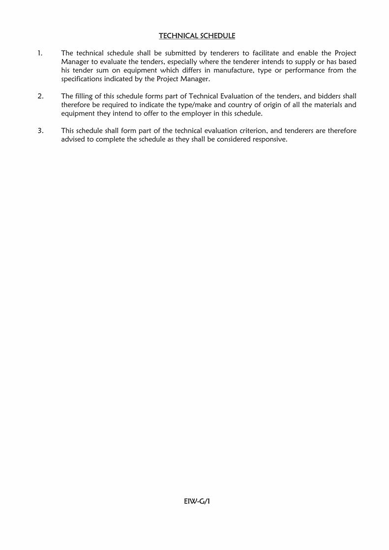
TECHNICAL SCHEDULE
1. The technical schedule shall be submitted by tenderers to facilitate and enable the ProjectManager to evaluate the tenders, especially where the tenderer intends to supply or has basedhis tender sum on equipment which differs in manufacture, type or performance from thespecifications indicated by the Project Manager.
2. The filling of this schedule forms part of Technical Evaluation of the tenders, and bidders shalltherefore be required to indicate the type/make and country of origin of all the materials andequipment they intend to offer to the employer in this schedule.
3. This schedule shall form part of the technical evaluation criterion, and tenderers are thereforeadvised to complete the schedule as they shall be considered responsive.
EIW-G/1

TECHNICAL SCHEDULE OF ITEMS TO BE SUPPLIED(To be completed by the Tenderer)
ITEM DESCRIPTION TYPE/MAKE MODELCOUNTRY OF
ORIGIN
1
2
3
4
5
6
7
8
9
10
11
12
13
14
15
16
17
18
19
20
21
22
23
Cable Trunking
Cable Accessories
HG PVC Conduits
Consumer unit/Distribution board
MCBs
MCCBs
Cables single core PVCI Copper
Armoured Copper (PVC/SWA/PVC)
PVC conduits
LV Switchboards
TPN Isolators
SPN Isolators
Internal Lighting Fittings
Outdoor Floodlights
Lighting Switches
Socket Outlets
DP Switches
Cooker Control Units
Fire Alarm & Detection Control Panel
Smoke Detectors
Heat Detectors
Manual Call Points
Lightning Protection System
Centralized Antenna System
EIW-G/2

SECTION H
STANDARD FORMS

CONTENTS OF SECTION H
TITLE PAGE
1. Key Personnel EIW-H/1
2. Schedule of Contracts completedin the last five (5) years EIW-H/2
3. Schedule of on-going projects EIW-H/3
4. Contractor’s Equipment EIW-H/4
5. Details of Litigation or ArbitrationProceedings EIW-H/5
6. Commissioning Guide for Electrical Installation works EIW-H/6–EIW-H/11
NOTE:
1.0 Tenderers must duly fill these Standard Forms as a mandatory requirement as they will formpart the evaluation criteria.

KEY PERSONNEL
Qualifications and experience of key personnel proposed for administration and execution ofthe Contract.
POSITION NAME
HIGHESTQUALIFICATION
(Attach proof)
YEARS OFEXPERIENCE(GENERAL)
YEARS OFEXPERIENCE IN
PROPOSEDPOSITION
1.
2.
3.
4.
5.
6.
7.
I certify that the above information is correct.
…………………….. ………………… …………………
Title Signature Date
EIW-H/1

CONTRACTS COMPLETED IN THE LAST FIVE (5) YEARS
Work performed on works of a similar nature, complexity and volume over the last 5 years.
PROJECT NAME NAME OF CLIENTTYPE OF WORKAND YEAR OFCOMPLETION
VALUE OFCONTRACT
(KSHS.)
I certify that the above works were successfully carried out and completed by ourselves.
………………………. …………………… ……………….
Title Signature Date
EIW-H/2

SCHEDULE OF ON-GOING PROJECTS
Details of on-going or committed projects, including expected completion date.
PROJECT NAME NAME OF CLIENT CONTRACTSUM
%COMPLETE
COMPLETIONDATE
I certify that the above works are currently being carried out by ourselves.
…………………. …….………… ………………….
Title Signature Date
EIW-H/3

SCHEDULE OF MAJOR ITEMS OF CONTRACTOR’S EQUIPMENT PROPOSED FORCARRYING OUT THE WORKS
ITEM OFEQUIPMENT
DESCRIPTION, MAKEAND AGE (Years)
CONDITION (New,good, poor) andnumber available
OWNED, LEASED(From whom?), orto be purchased(From whom?)
EIW-H/4

DETAILS OF LITIGATION OR ARBITRATION PROCEEDINGS IN WHICH THE TENDERER HASBEEN INVOLVED AS ONE OF THE PARTIES IN THE LAST 5 YEARSDETAILS OF LITIGATION OR ARBITRATION PROCEEDINGS IN WHICH THE TENDERER HASBEEN INVOLVED AS ONE OF THE PARTIES IN THE LAST 5 YEARS
1. …………………………………………………………………………………………………
2. …………………………………………………………………………………………………
3. …………………………………………………………………………………………………
4. …………………………………………………………………………………………………
5. …………………………………………………………………………………………………
6. …………………………………………………………………………………………………
7. …………………………………………………………………………………………………
8. …………………………………………………………………………………………………
9. …………………………………………………………………………………………………
10. …………………………………………………………………………………………………
EIW-H/5

Code: E/CG/01
REPUBLIC OF KENYA
MINISTRY OF TRANSPORT, INFRASTRUCTUTRE, PUBLIC WORKS,HOUSING & URBAN DEVELOPMENT
STATE DEPARTMENT OF PUBLIC WORKS(ELECTRICAL DEPARTMENT)
PROPOSED ADMINISTRATION BLOCK FOR SPECIAL ECONOMICZONES AUTHORITY (SEZA) AT DONGO KUNDU INDUSTRIAL
PARK, MOMBASA
W.P. ITEM NO. D117 CO/MSA/1902 JOB NO. 10676B
TESTING & COMMISSIONING GUIDE
FOR
ELECTRICAL INSTALLATION WORKS ON SITE
Issued by:
The Chief Engineer (Electrical),Ministry of Transport, Infrastructure, Public Works, Housing & Urban Development,State Department of Public Works,P. O.BOX 41191 – 00100 GPO,NAIROBI.
EIW-H/6

MINISTRY OF TRANSPORT, INFRASTRUCTURE, PUBLIC WORKS, HOUSING & URBANDEVELOPMENT
STATE DEPARTMENT OF PUBLIC WORKS
(ELECTRICAL DEPARTMENT)
TESTING AND COMMISSIONING OF ELECTRICAL INSTALLATION WORKS ON SITE.
PROJECT NAME..........................................................................................................................
W.P ITEM No..............................................................JOB No....................................................
PROJECT SITE..............................................................................................................................
CLIENT.........................................................................................................................................
The sub-contractor shall test in accordance with the relevant section of IEE regulations, Rule 3 of theElectrical Power Act for additional tests not covered by the regulations, Government Electricalspecifications I & II and the Kenya Power & Lighting Co. Ltd by-laws.
A PRELIMINARY CHECKS
The Engineer shall check to establish the following data:-
ITEM DESCRIPTION REMARKS
(i)Type of installation (New/Renovation/Addition/ toexisting installation)
(ii)
a) Power supply 240V/415V/11KV
b) Frequency of the mains supply
c) Installation power factor
…………………
…………………
…………………
(iii)Method of Metering (New /Monitoring/Existing
meter)
(iv) Are Testing/Measuring instruments available
(v)Are there maintenance/operational manuals forspecialized systems (if any)
(vi)
List of‘as installeddrawings’
Drg No. Description
EIW-H/7

B TESTS
ITEM TEST DESCRPTION OBSERVATIONS/RESULTS
REMARKS
1 Tests shall be carried out to ensure:
a) All fuses and single pole switches areinstalled in live conductor
b) All outlets and switched socket outletsare connected to ‘LIVE’ conductor inthe Terminal marked so and each earthpin effectively bonded to earthcontinuity system
c) Verify continuity of all final conductorsof each ‘Ring’ circuit. (0.05 to 0.8Ω) ……………………..Ohms
d) All radial circuits emanate fromrespective distribution boards/consumerunits and that they do not supply anyother Equipment
e) The correct phase sequence ismaintained throughout the installation
f) Effective ‘Discrimination’ in thearrangement of protective devices. i.e.a fault in the furthest powerpoint/Lighting point should not blowor trip Fuses/MCBs respective in theMeter board.
2 Inspect to ensure:
a) No terminal in the Ceiling Rose is ‘LIVE’when the corresponding switch is in theoff position.
b) All conduit termination conduit boxes,Consumer unit, DB’s and Adaptableboxes have smooth edges and areproperly bushed.
c) All fixed metal works close to Electricalinstallation are bonded to earthcontinuity conductor.
d) All Fuse ways and Circuit breakers forfinal sub circuits are properly labeled
EIW-H/8

B TESTS CONT’D
ITEM TEST DESCRPTION OBSERVATIONS/RESULTS
REMARKS
3 Carry out the following tests:
a) Insulation Resistance testsi) Between phases
a) R -Yb) R -Bc) B-Y
ii) Phase to Neutrala) R - Nb) R - Nc) B - N
iii) Phase to Eartha) R - Eb) R -Ec) B -E
Minimum thresholds for above and for:i) ELV circuits (SELV & PELV) = 0.25
MΩii) LV Circuits up to 500V = 0.5 MΩiii) LV Circuits above 500V = 1 MΩ
………………….. ……MΩ………………………..MΩ………………………..MΩ
………………………..MΩ………………….…….MΩ………………….…….MΩ
………………………..MΩ………………….…….MΩ………………….…….MΩ
b) Earth continuity conductorimpedance
(0.005 to 2Ω) ………………………..Ohms
c) Earth fault Loop impedance(0 - 2000 Ω) ……………………….Ohms
d) Earth Electrode resistance(Less than 4Ω) …………………….....Ohms
e) Earth Lead resistance(Less than 4Ω) ……………………….Ohms
f) The operation of protection MCCBS& MCBS (Tripping under faultyconditions)
g) Check the mechanical toggling (make& break) of all the switches toinstalled accessories.
4 Underground cabling, Check for:
i) Continuity of the phases
ii) Factory tests done (availcertification)
iii) Proper termination
iv) Route markers
EIW-H/9

B TESTS CONT’D
ITEM TEST DESCRPTION OBSERVATIONS/RESULTS
REMARKS
5 Installed loadi) Lighting points (No.)ii) Socket outlets (No.)iii) Motors (Give rating)iv) Other machines (Attach list if more)
Item Description Rating
6 Type of Earthing: TN-C/TN-S/ TN-C-S/TT/IT.
7 LV switchboard: The board shall be checked toascertain the followingi) Rating of the switchboardii) Rating of main incomer MCCB
iii) Form of construction (1/2B/3B/4)
iv) Degree of protection (IP rating)
v) Nameplates for identification of all circuitsentering/leaving switchgear
vi) Proper Electrical & Mechanical operation offunctional parts i.e MCCBs, Indicatingmeters, CTs & VTs .
vii) Check cable terminations, type & terminals
viii) General comments on the appearance of thefinished mechanical assembly includingwelding, full nuts & tightness of bolted parts.
8 Fireman’s switch.
i) Make and manufacturer
ii) The rating of the switch
iii) Test for the Electrical and Mechanicaloperation of the switch
iv) State the types of loads supported by themaintained board on the switch.
** see foot note
EIW-H/10

General comments on the Electrical installation:-
Testing and Commissioning witnessed by:
M.O.T.I.P.W.H&UD REPRESENTATIVE/ PROJECT ELECTRICAL ENGINEER:-
Name ………………….....................Designation……………………............
Sign………………………………… Date……………….…..……………….
CONTRACTOR’S REPRESENTATIVE:-
Name ………………….....................Designation……………………............
Sign………………………………… Date……………….…..…………….....
**If there are other defects/outstanding works noted, list them overleaf or on a separate sheet andattach.
EIW-H/11