voltage regulator controller - ge digital energy
TRANSCRIPT

GE Multilin's Quality Management System is
registered to ISO9001:2008
QMI # 005094
GE Digital Energy
GE Digital Energy
215 Anderson Avenue, Markham, Ontario
Canada L6E 1B3
Tel: (905) 294-6222 Fax: (905) 201-2098
Internet: http://www.gedigitalenergy.com
Instruction manualMultilin DGCV Revision: 1.10
Manual P/N: 1601-0259-A1
GE publication code: GEK-113577
Copyright © 2011 GE Digital Energy
*1601-0259-A1*
The Multilin DGCVVoltage Regulator Controller

© 2011 GE Digital Energy Incorporated. All rights reserved.
Multilin DGCV Voltage Regulator Controller instruction manual for revision 1.10.
Multilin DGCV Voltage Regulator Controller, EnerVista, EnerVista Launchpad, and EnerVista DGCV Setup are registered trademarks of GE Digital Energy Inc.
The contents of this manual are the property of GE Digital Energy Inc. This documentation is furnished on license and may not be reproduced in whole or in part without the permission of GE Digital Energy. The content of this manual is for informational use only and is subject to change without notice.
Part number: 1601-0259-A1 (July 2011)

MULTILIN DGCV VOLTAGE REGULATOR CONTROLLER – INSTRUCTION MANUAL TOC–I
Table of Contents
1.INTRODUCTION Overview ................................................................................................................................1 - 1Cautions and warnings ...................................................................................................1 - 4DGC control functions......................................................................................................1 - 5
Basic control functions ..........................................................................................................1 - 5Supplementary control functions .....................................................................................1 - 6Inhibit functions ........................................................................................................................1 - 6
Multilin DGCV order codes .............................................................................................1 - 8Specifications.......................................................................................................................1 - 9
Inputs .............................................................................................................................................1 - 9Outputs..........................................................................................................................................1 - 10Power supply ..............................................................................................................................1 - 10Communications ......................................................................................................................1 - 10Testing and Certification.......................................................................................................1 - 10Environmental............................................................................................................................1 - 12
2.INSTALLATION Mechanical installation ...................................................................................................2 - 1Electrical installation ........................................................................................................2 - 2
3.INTERFACES Front control panel interface........................................................................................3 - 1Working with the Keypad .....................................................................................................3 - 7LED status indicators..............................................................................................................3 - 9
Software setup ....................................................................................................................3 - 10EnerVista Multilin DGCV Setup Software .......................................................................3 - 10Connecting EnerVista DGCV Setup to the device......................................................3 - 13Working with settings and settings files........................................................................3 - 16Upgrading Multilin DGCV firmware..................................................................................3 - 23Advanced EnerVista DGCV Setup features ..................................................................3 - 24
4.ACTUAL VALUES A1 Status ................................................................................................................................4 - 2Clock ...............................................................................................................................................4 - 3Contact inputs ...........................................................................................................................4 - 3Output relays..............................................................................................................................4 - 3Virtual inputs...............................................................................................................................4 - 4Virtual outputs ...........................................................................................................................4 - 4Contact inputs summary ......................................................................................................4 - 4Output relays summary ........................................................................................................4 - 4Flexlogic summary...................................................................................................................4 - 5Tap position.................................................................................................................................4 - 5Active group................................................................................................................................4 - 5
A2 Metering...........................................................................................................................4 - 6Current...........................................................................................................................................4 - 8Voltage ..........................................................................................................................................4 - 8Power .............................................................................................................................................4 - 9Frequency ....................................................................................................................................4 - 10Total Harmonic Distortion (THD)........................................................................................4 - 10Harmonics ...................................................................................................................................4 - 11Default screens .........................................................................................................................4 - 13Power calculation.....................................................................................................................4 - 13
A3 Records ............................................................................................................................4 - 15

TOC–II MULTILIN DGCV VOLTAGE REGULATOR CONTROLLER – INSTRUCTION MANUAL
Event records.............................................................................................................................4 - 15Data logger .................................................................................................................................4 - 16
A4 Target messages.........................................................................................................4 - 18Multilin DGCV configuration errors ..................................................................................4 - 18
5.SETTINGS S1 Product setup................................................................................................................5 - 1Clock...............................................................................................................................................5 - 3Password security ...................................................................................................................5 - 4Communications......................................................................................................................5 - 5Event recorder...........................................................................................................................5 - 13Datalogger ..................................................................................................................................5 - 14Front panel..................................................................................................................................5 - 15Installation...................................................................................................................................5 - 15
S2 System setup.................................................................................................................5 - 16Current sensing.........................................................................................................................5 - 17Voltage sensing ........................................................................................................................5 - 17Power system ............................................................................................................................5 - 18Tap changer ...............................................................................................................................5 - 18Tap sensing.................................................................................................................................5 - 19
S3 Voltage regulator ........................................................................................................5 - 24Main regulation.........................................................................................................................5 - 28Runback limits ...........................................................................................................................5 - 30Voltage reduction ....................................................................................................................5 - 31Power override ..........................................................................................................................5 - 32Inhibit functions ........................................................................................................................5 - 33Tap Changer control logic ...................................................................................................5 - 34
S4 Controls............................................................................................................................5 - 38Change settings group.......................................................................................................... 5 - 39Modes of VR operation .......................................................................................................... 5 - 40FlexLogic™ ..................................................................................................................................5 - 44
S5 Inputs/Outputs .............................................................................................................5 - 49Contact inputs ...........................................................................................................................5 - 49Output relays .............................................................................................................................5 - 50Virtual inputs ..............................................................................................................................5 - 51
6.COMMANDS
7.MAINTENANCE M1 Product information..................................................................................................7 - 2M3 Statistics .........................................................................................................................7 - 3

MULTILIN DGCV VOLTAGE REGULATOR CONTROLLER – INSTRUCTION MANUAL 1–1
Multilin DGCV Voltage Regulator Controller
Chapter 1: Introduction
Digital Energy
Introduction
Overview
Multilin DGCV applicationThe Distribution Grid Controller - Voltage Regulator (Multilin DGCV ) is a voltage regulating device intended for the regulation of the power transformer secondary (load) voltage within user-specified limits. The Multilin DGCV performs this regulation by sending either a Raise or a Lower tap command to the transformer on-load tap changer. In return, the tap changer device switches the tap of the transformer secondary winding to a higher or lower tap number, and effectively changes the transformer primary-to-secondary voltage ratio. Multilin DGCV description of operationThe Multilin DGCV can be connected to measure either phase-to-ground, or phase-to-phase, single voltage input, or three-phase voltages. The device can also be connected to either single phase current input, or three phase currents. When the Multilin DGCV is to be used with single-phase current and voltage inputs, it is highly recommended that these inputs be taken from the CT and PT mounted on the same phase. Based on the programmed required voltage level and the entered line drop compensation (LDC), the Multilin DGCV calculates the control voltage and compares it with the measured secondary voltage. When the voltage difference becomes bigger than the calculated limit, the controller in one case sends a raise, and in other case, a lower, tap command. The raising or the lowering of the tap is not an instantaneous action. The Multilin DGCV will not send a raise or lower tap command to the tap changer if the measured voltage fluctuates within the user-specified voltage bandwidth. When the measured voltage exceeds either the lower or higher bandwidth level, the Multilin DGCV starts the user-programmed computation delay timer. If during that time-out period, the measured voltage falls back to within the voltage bandwidth, the timer resets and the raise or lower tap change command is not initiated. The tap change command will be initiated after the computation delay time expires. Please note that upon a successful tap change, the measured voltage may still be outside the voltage bandwidth. If the voltage is still “out of band,” the voltage regulator will issue another tap change command either after applying

1–2 MULTILIN DGCV VOLTAGE REGULATOR CONTROLLER – INSTRUCTION MANUAL
OVERVIEW CHAPTER 1: INTRODUCTION
a computation time delay, or without a time delay. Applying or not applying a computation time delay before each tap change command will depend on the selected regulation mode: sequential, or non-sequential. In Sequential mode, the computation time delay is timed-out only for the first tap change. With the voltage still “out of band”, the Multilin DGCV continues to change the tap until the voltage is brought back into the band without applying a computation time delay.In Non-sequential mode, each raise or lower tap command is issued after the computation time delay times out and a successful tap change is made. The regulator increases one tap in each stage until the voltage is again within limits.In both modes the Multilin DGCV applies a user-programmed tap changer delay to allow time for the physical tap change completion, and to sense whether the measured voltage has changed.
Figure 1: Multilin DGCV control application

CHAPTER 1: INTRODUCTION OVERVIEW
MULTILIN DGCV VOLTAGE REGULATOR CONTROLLER – INSTRUCTION MANUAL 1–3
Multilin DGCV Features
• Single or three phase voltage and currents measurements
• Stable transformer secondary voltage regardless the loading conditions
• Voltage level, voltage bandwidth, Line Drop Compensation (LDC)
• Voltage runback limits
• Three levels of voltage reduction
• Reverse power detection and power override modes
• Under-voltage, over-voltage and over-current inhibits
• Tap change incomplete sequence detection
• Unsuccessful tap change detection
• Auto/Remote and Manual control
• Easy control both through faceplate and remotely
• Data monitoring and control over radio communication via Modbus or DNP addressing.
1–4 MULTILIN DGCV VOLTAGE REGULATOR CONTROLLER – INSTRUCTION MANUAL
CAUTIONS AND WARNINGS CHAPTER 1: INTRODUCTION
Cautions and warnings
Before attempting to install or use this device, it is imperative that all caution and danger indicators in this manual are reviewed to help prevent personal injury, equipment damage, or downtime. The following icons are used to indicate notes, cautions, and dangers.
Figure 2: Note icons used in the documentation
The standard note icon emphasizes a specific point or indicates minor problems that may occur if instructions are not properly followed.The caution icon indicates that possible damage to equipment or data may occur if instructions are not properly followed.The danger icon provides users with a warning about the possibility of serious or fatal injury to themselves or others.
NOTE CAUTION DANGER

CHAPTER 1: INTRODUCTION MULTILIN DGCV CONTROL FUNCTIONS
MULTILIN DGCV VOLTAGE REGULATOR CONTROLLER – INSTRUCTION MANUAL 1–5
Multilin DGCV control functions
Basic control functionsVoltage Regulator basic control includes settings used for most installations:Voltage Level (Bandcenter)The Voltage Level is programmable on the Multilin DGCV to define the desired level of voltage to be held at the load side of the power transformer. The actual load is usually away from the transformer, in which case the electrical distance to the load is defined by the line drop compensation (LDC) settings. In many cases this voltage level is set to 120 V secondary value, that corresponds to the desired primary voltage from the transformer load side. It is commonly required that the voltage at the load be held in the range of 114 V to 126 V, although the voltage level setting range provides selecting an even higher voltage difference.Voltage BandwidthDue to the variations in the loads connected to the transformer, its output voltage also varies. Two criteria apply to this fluctuation:
1. Acceptable voltage fluctuation levels when the voltage level stays within the selected voltage bandwidth
2. Unacceptable voltage levels – voltages outside the bandwidth voltage thresholds, and emergency voltage levels much higher, or much lower than the bandwidth voltage thresholds.
Usually the magnitude of the voltage bandwidth half is considered to be twice the voltage change per the LTC step change, or 1.5 V volts in the common system. In fact the most common bandwidth settings for tight voltage regulation are 2.0, 2.5 and 3.0 volts. Time Delay (Computation Time Delay)The Multilin DGCV includes a time delay known as Computation Time delay that is used to delay operation of the tap changer, should the excursion of the measured voltage outside of the bandwidth be of short duration. An example of a short voltage dip can be the starting of a motor connected to the bus supplied by the transformer, where the tap changer should not raise the tap for that start period. The time delay is usually set to tens of seconds, and even as much as a few minutes, depending on the situation.Line Drop Compensation (LDC)Very often the regulators are installed far from the loads, and the voltage levels measured at the transformer output, at the loads, or at the theoretical load center, are very different. The greater the distance, the greater the voltage difference between the transformer output voltage and the voltage at the load point, with the latter being smaller. To supply the required voltage at the load center point, the tap changer needs to raise the voltage at the transformer side to a much higher level. To avoid such tap changer action, the Line Drop Compensation is calculated by the Voltage Regulator and applied to the computation of the desired control voltage. The LDC settings define the resistive drop compensation and the inductive drop compensation expressed in volts. The value to be set on the control is the voltage drop on the line when the line is carrying CT rated primary current.
- power factor angle
V line drop
Vb
VI
IR
IX
I
VI = Vb - V line drop
Ø

1–6 MULTILIN DGCV VOLTAGE REGULATOR CONTROLLER – INSTRUCTION MANUAL
MULTILIN DGCV CONTROL FUNCTIONS CHAPTER 1: INTRODUCTION
Vl – voltage at the load pointVb – bus voltage IR – voltage drop due to line resistanceIX – voltage drop due to line inductance
Supplementary control functionsVOLTAGE OVERRIDE FUNCTIONSHigh and Low Voltage Runback LimitsWhen set, the VR applies additional bandwidth to the Voltage Level setting. The purpose of this function is to avoid voltage hunting if the measured voltage changes to either a very low, or a very high, level. If the Voltage Level exceeds the runback limits, the voltage regulator will immediately call for an automatic raising or lowering of the tap without any time delay. The lower (raise) tap command will continue until the voltage falls to within the voltage runback deadband. This function is used in cases where under normal operations, heavy loads on the system with line drop compensation may result in excessive high voltage levels to which the first users fed by that transformer are subjected.Voltage ReductionThis function can be used in cases where system-wide voltage reduction is imposed in order to reduce demand at critical periods. Sometimes a small voltage “boost” from a tapped autotransformer at the voltage sensing side, can “fool” the AVR that would in return issue a command to the transformer tap changer to lower the output voltage. These voltage “boosts” are in steps of typically 2.5, 5.0, and 7.5 percent. To avoid issuing a command for lowering the voltage, the AVR provides an automatic voltage reduction function. This function uses three digital inputs, each of which, if activated, will reduce the voltage limit setpoint by the programmed percentage.Reverse PowerNormally the Multilin DGCV is connected to CT and VT on the secondary side of the transformer in order to sense forward power. However, should the power change its direction, the regulator will detect it and apply control according to the programmed reverse power settings. If IGNORE mode is selected, the detection of reverse power does not result in any action. When BLOCK mode is selected, the regulator will be blocked from issuing raise (lower) tap changer commands, until the detected reverse power goes below the programmed pickup level. Another selection, RETURN TO NORMAL, would lead to changing the tap position to the neutral tap, and if REGULATE mode is selected, the detection of reverse power reverses the Raise/Lower operations.
Inhibit functionsOver- Current InhibitOver-current inhibit is applied to the VR control to prevent the tap changer from raising or lowering the tap position, preventing tap contact wear in periods of severe overloading or low level faults. Over-Voltage InhibitIn some cases, over-voltage inhibiting is applied to prevent further tap-raising action due to load increase, which would, in turn, demand higher voltage at the transformer side. When the measured voltage at the transformer output goes above the over-voltage inhibit threshold, the tap changer stops raising the tap. Under-Voltage InhibitUnder-voltage inhibit is applied to prevent further tap-lowering and raising actions, in order to limit low customer voltage to safe limits, and block further voltage reduction action that could cause motor stalling and other undesirable low voltage effects.The undervoltage blocking is applied to prevent tap change operation during a system breakdown; to avoid the tap changer mechanism from being driven to the last tap.

CHAPTER 1: INTRODUCTION MULTILIN DGCV CONTROL FUNCTIONS
MULTILIN DGCV VOLTAGE REGULATOR CONTROLLER – INSTRUCTION MANUAL 1–7
Tap changer voltage control levels are depicted in the following diagram:
Figure 3: Voltage Regulation Control Levels and Inhibits
Balanced VoltageIf the voltage level is maintained within the selected voltage bandwidth levels [(b) in the above figure], no raise or lower tap command is issued.Normal Tap Lower/Raise intervalWithin this band, if the VR is in auto mode, once the voltage is out of any of the bandwith limits [(b) in the above figure] a counter is initiated. When the counter times out, a lower or raise tap command is issued.Fast Tap Lower/Raise intervalWhen the Voltage Level exceeds any of the voltage runback limits [(b) in the above figure], the Voltage Regulator is required to perform an immediate action. A quick raise/lower tap without time delay is issued. The Runback limits are programmed with respect to the computed voltage at the load side. The OV & UV limits [(a) in the above figure] are applied directly to the measured voltage at the transformer output side. The OV limit inhibits any possible raising of the tap. The auto lower tap commands are allowed. The UV limit, inhibits automatic control until the measured voltage is again above this threshold.

1–8 MULTILIN DGCV VOLTAGE REGULATOR CONTROLLER – INSTRUCTION MANUAL
MULTILIN DGCV ORDER CODES CHAPTER 1: INTRODUCTION
Multilin DGCV order codes
Figure 4: Order Codes
CHAPTER 1: INTRODUCTION SPECIFICATIONS
MULTILIN DGCV VOLTAGE REGULATOR CONTROLLER – INSTRUCTION MANUAL 1–9
Specifications
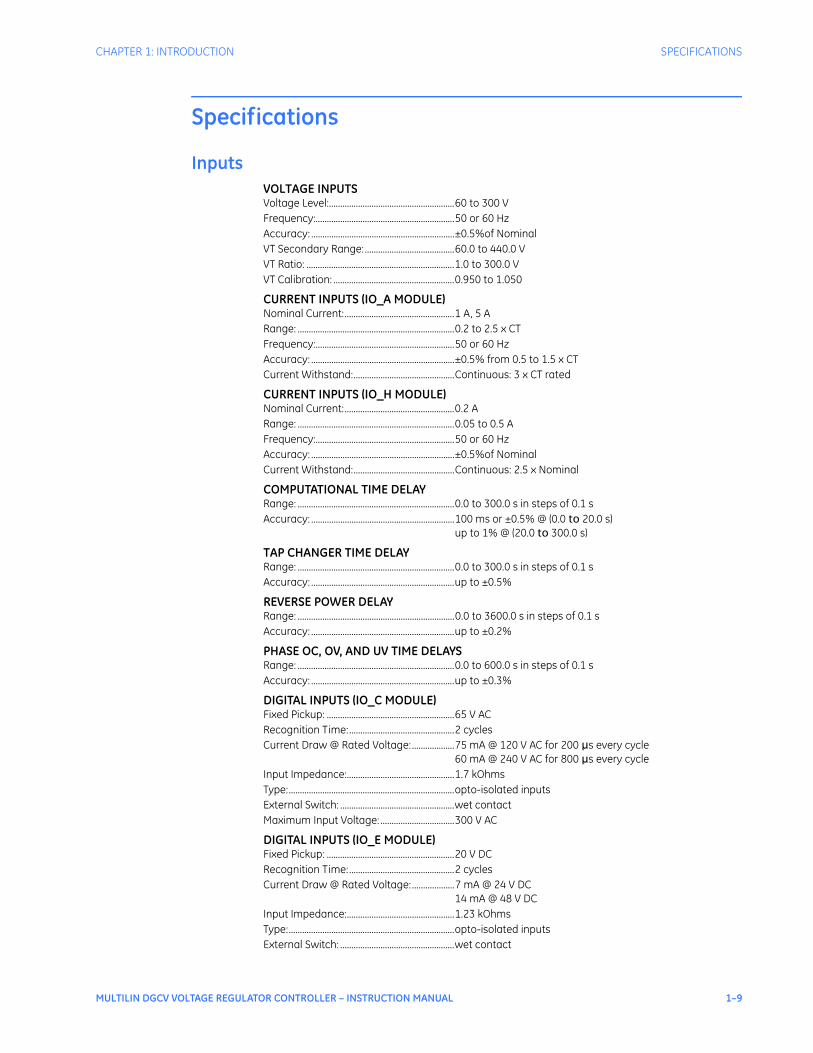
InputsVOLTAGE INPUTSVoltage Level:........................................................60 to 300 VFrequency:..............................................................50 or 60 HzAccuracy: ................................................................±0.5%of NominalVT Secondary Range: ........................................60.0 to 440.0 VVT Ratio: ..................................................................1.0 to 300.0 VVT Calibration: ......................................................0.950 to 1.050
CURRENT INPUTS (IO_A MODULE)Nominal Current:.................................................1 A, 5 ARange: ......................................................................0.2 to 2.5 x CTFrequency:..............................................................50 or 60 HzAccuracy: ................................................................±0.5% from 0.5 to 1.5 x CTCurrent Withstand:.............................................Continuous: 3 x CT rated
CURRENT INPUTS (IO_H MODULE)Nominal Current:.................................................0.2 ARange: ......................................................................0.05 to 0.5 AFrequency:..............................................................50 or 60 HzAccuracy: ................................................................±0.5%of NominalCurrent Withstand:.............................................Continuous: 2.5 x Nominal
COMPUTATIONAL TIME DELAYRange: ......................................................................0.0 to 300.0 s in steps of 0.1 sAccuracy: ................................................................100 ms or ±0.5% @ (0.0 to 20.0 s)
up to 1% @ (20.0 to 300.0 s)
TAP CHANGER TIME DELAYRange: ......................................................................0.0 to 300.0 s in steps of 0.1 sAccuracy: ................................................................up to ±0.5%
REVERSE POWER DELAYRange: ......................................................................0.0 to 3600.0 s in steps of 0.1 sAccuracy: ................................................................up to ±0.2%
PHASE OC, OV, AND UV TIME DELAYSRange: ......................................................................0.0 to 600.0 s in steps of 0.1 sAccuracy: ................................................................up to ±0.3%
DIGITAL INPUTS (IO_C MODULE)Fixed Pickup: .........................................................65 V ACRecognition Time:...............................................2 cyclesCurrent Draw @ Rated Voltage:...................75 mA @ 120 V AC for 200 μs every cycle
60 mA @ 240 V AC for 800 μs every cycleInput Impedance:................................................1.7 kOhmsType:..........................................................................opto-isolated inputsExternal Switch: ...................................................wet contactMaximum Input Voltage: .................................300 V AC
DIGITAL INPUTS (IO_E MODULE)Fixed Pickup: .........................................................20 V DCRecognition Time:...............................................2 cyclesCurrent Draw @ Rated Voltage:...................7 mA @ 24 V DC
14 mA @ 48 V DCInput Impedance:................................................1.23 kOhmsType:..........................................................................opto-isolated inputsExternal Switch: ...................................................wet contact

1–10 MULTILIN DGCV VOLTAGE REGULATOR CONTROLLER – INSTRUCTION MANUAL
SPECIFICATIONS CHAPTER 1: INTRODUCTION
OutputsOUTPUT RELAYSConfiguration: ...................................................... electromechanical form A (IO_C) and form C (IO_D)Contact Material: ................................................ silver alloyOperate Time: ......................................................10 msMinimum Contact Load:..................................10 mA @ 5 V DCContinuous Current: ..........................................10 AMake and Carry for 0.2 s: ................................30 A per ANSI C37.90Mechanical Life: ..................................................10 000 000 operations
RAISE/LOWER FORM A OUTPUT RELAYSAC Resistive, 120 V AC: .....................................10 AAC Resistive, 240 V AC: .....................................10 AAC Inductive, PF = 0.4 pilot duty: .................2 ADC Resistive, 30 V DC: .......................................10 A
FORM C OUTPUT CONTACTSAC Resistive, 120 V AC: .....................................10 A normally open, 5 A normally closedAC Resistive, 240 V AC: .....................................10 A normally open, 8 A normally closedAC Inductive, PF = 0.4 pilot duty: .................2.5 ADC Resistive, 30 V DC: .......................................10 A
Power supplyPOWER SUPPLYNominal:..................................................................120 to 240 V AC
125 to 250 V DCRange: ......................................................................60 to 300 V AC (50 and 60 Hz)
84 to 250 V DCRide Through: .......................................................35 msVoltage Withstand: ............................................2 x highest nominal voltage for 10 msPower Consumption:.........................................16 W typical, 25 W maximum
CommunicationsCOMMUNICATIONSTransmission Mode: .......................................... radio (optional)Communication Protocols:.............................DNP 3, Modbus
Testing and Certification
APPROVALS
Applicable Council Directive According to
CE compliance Low voltage directive EN60255-5 / EN60255-27
EMC Directive EN61000-6-2 / 6-4
ISO Manufactured under a registered quality program
ISO9001

CHAPTER 1: INTRODUCTION SPECIFICATIONS
MULTILIN DGCV VOLTAGE REGULATOR CONTROLLER – INSTRUCTION MANUAL 1–11
TYPE TESTS
Test Reference Standard Test Level
Dielectric Voltage Withstand EN60255-5 2.3KV
Impulse Voltage Withstand EN60255-5 5KV
Insulation Resistance Test EN60255-5 500 VDC
Damped Oscillatory IEC61000-4-18IEC60255-22-1 2.5KV CM, 1KV DM
Electrostatic Discharge EN61000-4-2/IEC60255-22-2 Level 4
RF Immunity EN61000-4-3/IEC60255-22-3 Level 3
Fast Transient Disturbance EN61000-4-4/IEC60255-22-4 Class A and B
Surge Immunity EN61000-4-5/IEC60255-22-5 Level 3 & 4
Conducted RF Immunity EN61000-4-6/IEC60255-22-6 Level 3
Radiated & Conducted Emissions CISPR11 /CISPR22/ IEC60255-25 Class A
Sinusoidal Vibration IEC60255-21-1 Class 1
Shock & Bump IEC60255-21-2 Class 1
Siesmic IEC60255-21-3 Class 2
Power Magnetic Immunity IEC61000-4-8 Level 5
Voltage Dip & interruption IEC61000-4-11 0, 40, 70, 80% dips, 250/300 cycle interrupts
Environmental (Cold) IEC60068-2-1 -20C 16 hrs
Environmental (Cold Storage) IEC60068-2-1 -40C 16 hrs
Environmental (Dry heat) IEC60068-2-2 85C 16hrs
Relative Humidity Cyclic IEC60068-2-30 6day variant 2
RF Immunity IEEE/ANSIC37.90.2 20V/m 80-1Ghz

1–12 MULTILIN DGCV VOLTAGE REGULATOR CONTROLLER – INSTRUCTION MANUAL
SPECIFICATIONS CHAPTER 1: INTRODUCTION
Environmental
ENVIRONMENTAL SPECIFICATIONS
Ambient temperatures:
Storage/shipping: - 40oC to 90oC *
Operating: -40oC to 60oC *
* 1" around Base Unit
Humidity: Operating up to 95% (non condensing) @ 55oC (As per IEC60068-2-30 Variant 2, 6days)
Altitude: 2000m (max)
Overvoltage Category: II
Ingress Protection: IP20 (Base Unit) IP54 (Control Panel)
Environmental rating: 60oC surrounding air
Pollution Degree: II
Type 1 (panel mount versions only)
MULTILIN DGCV VOLTAGE REGULATOR CONTROLLER – INSTRUCTION MANUAL 2–1
Multilin DGCV Voltage Regulator Controller
Chapter 2: Installation
Digital Energy
Installation
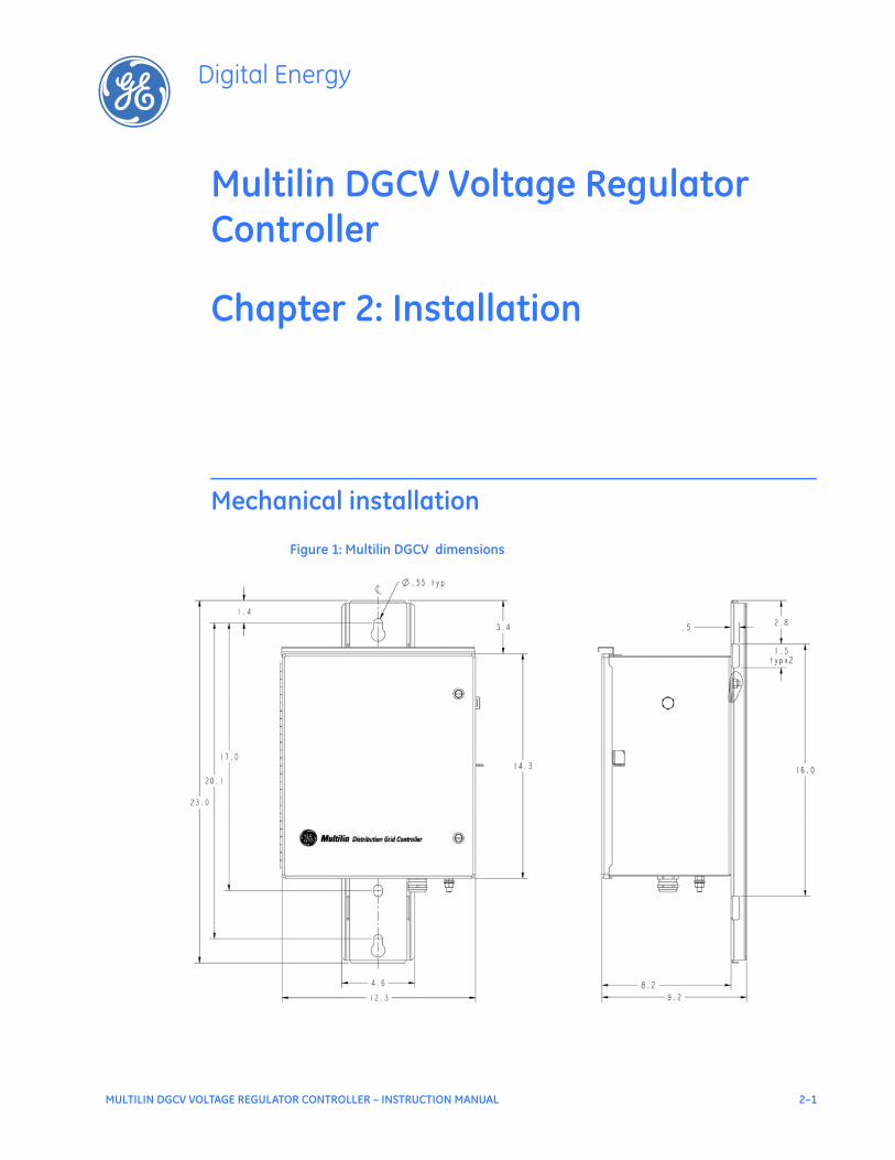
Mechanical installation
Figure 1: Multilin DGCV dimensions
2–2 MULTILIN DGCV VOLTAGE REGULATOR CONTROLLER – INSTRUCTION MANUAL
ELECTRICAL INSTALLATION CHAPTER 2: INSTALLATION
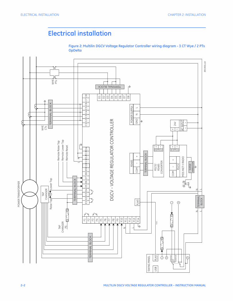
Electrical installation
Figure 2: Multilin DGCV Voltage Regulator Controller wiring diagram - 3 CT Wye / 2 PTs OpDelta
E1
E2
E3
E4
E5
E6
E7
E8
E9
E1
0E
11
E1
2E
13
E1
4C
1C
2C
3C
4C
5C
6C
7C
8F
1
F2
F3
F4
F5 F6
F7
F8
F9
F1
0
F1
1
F1
2
F1
3
F1
4
D1
D2
D3
D4
D5
D6
D7
D8
CO
M-
+
RS
48
5
GN
DN
L
PO
WE
RS
UP
PLY
DG
CV
-V
OLT
AG
ER
EG
UL
ATO
RC
ON
TRO
LLE
R
TE
RM
INA
LB
LO
CK
TER
MIN
AL
BLO
CK
RS
23
2R
S4
85
CO
NV
ER
TER
POWER
-+U
SB
RJ4
5F
RO
NT
PO
RT
SW
ING
PA
NE
L
RJ4
5F
RO
NT
PO
RT
TER
MIN
AL
BLO
CK
POWER
-+C
OM
-+
RS
23
2
MD
SIN
ET
IIR
AD
IO
SU
RG
EA
RR
ES
TOR
AC
INP
UT
~~
-+2
4V
TAP
CH
AN
GE
R
M
Re
mo
teR
ais
eTa
p
Re
mo
teLo
we
rTa
p
LN
LNN L
3A
3A
L N M
NL
RJ4
5
3A
TAP
CH
AN
GE
RP
S
89
19
00
.cd
r
Ra
ise
Tap
Low
er
Tap
TE
RM
INA
LB
LO
CK
Re
mo
teR
ese
t
TE
RM
INA
LB
LO
CK
TERMINALBLOCK
N L
PO
WE
RTR
AN
SF
OR
ME
R
WY
EC
Ts
WY
EP
Ts
Inte
rna
l
Ext
ern
al
Off
CHAPTER 2: INSTALLATION ELECTRICAL INSTALLATION
MULTILIN DGCV VOLTAGE REGULATOR CONTROLLER – INSTRUCTION MANUAL 2–3
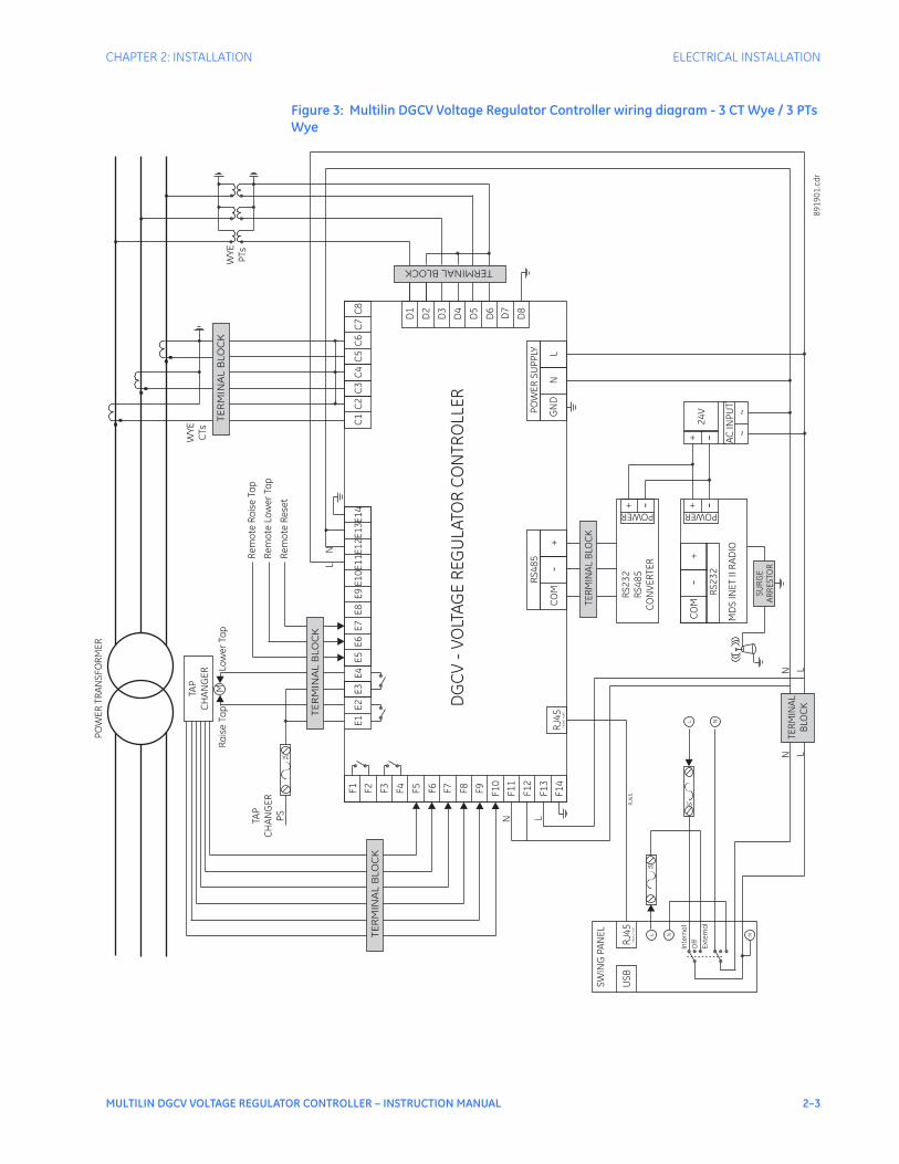
Figure 3: Multilin DGCV Voltage Regulator Controller wiring diagram - 3 CT Wye / 3 PTs Wye
E1
E2
E3
E4
E5
E6
E7
E8
E9
E1
0E
11
E1
2E
13
E1
4C
1C
2C
3C
4C
5C
6C
7C
8F
1
F2
F3
F4
F5 F6
F7
F8
F9
F1
0
F1
1
F1
2
F1
3
F1
4
D1
D2
D3
D4
D5
D6
D7
D8
CO
M-
+
RS
48
5
GN
DN
L
PO
WE
RS
UP
PLY
DG
CV
-V
OLT
AG
ER
EG
UL
ATO
RC
ON
TRO
LLE
R
TE
RM
INA
LB
LO
CK
TER
MIN
AL
BLO
CK
RS
23
2R
S4
85
CO
NV
ER
TER
POWER-+
US
BR
J45
FR
ON
TP
OR
T
SW
ING
PA
NE
L
RJ4
5F
RO
NT
PO
RT
TER
MIN
AL
BLO
CK
POWER
-+C
OM
-+
RS
23
2
MD
SIN
ET
IIR
AD
IO
SU
RG
EA
RR
ES
TOR
AC
INP
UT
~~
-+2
4V
TAP
CH
AN
GE
R
M
Re
mo
teR
ais
eT a
p
Re
mo
teLo
we
rTa
p
LN
LNN L
3A
3A
L N M
NL
RJ4
5
3A
TAP
CH
AN
GE
RP
S
89
19
01
.cd
r
Ra
ise
Tap
Low
er
Tap
TE
RM
INA
LB
LO
CK
Re
mo
teR
ese
t
TE
RM
INA
LB
LO
CK
TERMINALBLOCK
N L
PO
WE
RTR
AN
SF
OR
ME
R
WY
EC
Ts
WY
EP
Ts
Inte
rna
l
Ext
ern
al
Off
2–4 MULTILIN DGCV VOLTAGE REGULATOR CONTROLLER – INSTRUCTION MANUAL
ELECTRICAL INSTALLATION CHAPTER 2: INSTALLATION
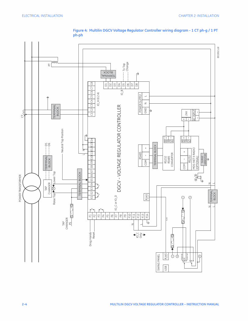
Figure 4: Multilin DGCV Voltage Regulator Controller wiring diagram - 1 CT ph-g / 1 PT ph-ph
E1
E2
E3
E4
E5
E6
E7
E8
E9
E1
0E
11
E1
2E
13
E1
4C
1C
2C
3C
4C
5C
6C
7C
8F
1
F2
F3
F4
F5 F6
F7
F8
F9
F1
0
F1
1
F1
2
F1
3
F1
4
D1
D2
D3
D4
D5
D6
D7
D8
CO
M-
+
RS
48
5
GN
DN
L
PO
WE
RS
UP
PLY
DG
CV
-V
OLT
AG
ER
EG
UL
ATO
RC
ON
TRO
LLE
R
TE
RM
INA
LB
LO
CK
TER
MIN
AL
BLO
CK
RS
23
2R
S4
85
CO
NV
ER
TER
POWER
-+U
SB
RJ4
5F
RO
NT
PO
RT
SW
ING
PA
NE
L
RJ4
5F
RO
NT
PO
RT
TER
MIN
AL
BLO
CK
POWER
-+C
OM
-+
RS
23
2
MD
SIN
ET
IIR
AD
IO(O
PTI
ON
AL)
SU
RG
EA
RR
ES
TOR
AC
INP
UT
~~
-+2
4V
TAP
CH
AN
GE
R
M
Ne
utr
alT
ap
Po
siti
on
LN
LNN L
3A
3A
L N M
NL
RJ4
5
3A
TAP
CH
AN
GE
RP
S
89
19
02
.cd
r
Ra
ise
Tap
Low
er
Tap
TE
RM
INA
LB
LO
CK
TERMINALBLOCK
N L
PO
WE
RTR
AN
SF
OR
ME
RC
T
PT
Inte
rna
l
Ext
ern
al
Off
IO_
Co
rIO
_D
IO_
H(0
.2A
)
IO_
BTo
Tap
Ch
an
ge
Dra
gH
an
ds
Re
set
TE
RM
INA
LB
LO
CK
D5
D6
IO_
CO
nly

CHAPTER 2: INSTALLATION ELECTRICAL INSTALLATION
MULTILIN DGCV VOLTAGE REGULATOR CONTROLLER – INSTRUCTION MANUAL 2–5
Figure 5: Multilin DGCV Voltage Regulator Controller wiring diagram - 1 CT ph-g / 1 PT ph-g
E1
E2
E3
E4
E5
E6
E7
E8
E9
E1
0E
11
E1
2E
13
E1
4C
1C
2C
3C
4C
5C
6C
7C
8F
1
F2
F3
F4
F5 F6
F7
F8
F9
F1
0
F1
1
F1
2
F1
3
F1
4
D1
D2
D3
D4
D5
D6
D7
D8
CO
M-
+
RS
48
5
GN
DN
L
PO
WE
RS
UP
PLY
DG
CV
-V
OLT
AG
ER
EG
UL
ATO
RC
ON
TRO
LLE
R
TE
RM
INA
LB
LO
CK
TER
MIN
AL
BLO
CK
RS
23
2R
S4
85
CO
NV
ER
TER
POWER-+
US
BR
J45
FR
ON
TP
OR
T
SW
ING
PA
NE
L
RJ4
5F
RO
NT
PO
RT
TER
MIN
AL
BLO
CK
POWER
-+C
OM
-+
RS
23
2
MD
SIN
ET
IIR
AD
IO(O
PTI
ON
AL)
SU
RG
EA
RR
ES
TOR
AC
INP
UT
~~
-+2
4V
TAP
CH
AN
GE
R
M
Ne
utr
al T
ap
Po
siti
on
LN
LNN L
3A
3A
L N M
NL
RJ4
5
3A
TAP
CH
AN
GE
RP
S
89
19
03
.cd
r
D5
Low
er
Tap
TE
RM
INA
LB
LO
CK
TERMINALBLOCK
N L
PO
WE
RTR
AN
SF
OR
ME
RC
T
PT
Inte
rna
l
Ext
ern
al
Off
TE
RM
INA
LB
LO
CK
ToTa
pC
ha
ng
er
D6
IO_
Co
rIO
_D
IO_
CO
nly
Dra
gH
an
dR
ese
t
IO_
H(0
.2A
)
IO_
B

2–6 MULTILIN DGCV VOLTAGE REGULATOR CONTROLLER – INSTRUCTION MANUAL
ELECTRICAL INSTALLATION CHAPTER 2: INSTALLATION
Figure 6: Multilin DGCV Voltage Regulator Controller wiring diagram - 1 CT ph-g / 1 PT ph-g - for 1-phase Voltage Regulator
E1
E2
E3
E4
E5
E6
E7
E8
E9
E1
0E
11
E1
2E
13
E1
4C
1C
2C
3C
4C
5C
6C
7C
8F
1
F2
F3
F4
F5 F6
F7
F8
F9
F1
0
F1
1
F1
2
F1
3
F1
4
D1
D2
D3
D4
D5
D6
D7
D8
CO
M-
+
RS
48
5
GN
DN
L
PO
WE
RS
UP
PLY
DG
CV
-V
OLT
AG
ER
EG
UL
ATO
RC
ON
TRO
LLE
R
TE
RM
INA
LB
LO
CK
TER
MIN
AL
BLO
CK
RS
23
2R
S4
85
CO
NV
ER
TER
POWER
-+U
SB
RJ4
5F
RO
NT
PO
RT
SW
ING
PA
NE
L
RJ4
5F
RO
NT
PO
RT
TER
MIN
AL
BLO
CK
POWER
-+C
OM
-+
RS
23
2
MD
SIN
ET
IIR
AD
IO(O
PTI
ON
AL)
SU
RG
EA
RR
ES
TOR
AC
INP
UT
~~
-+2
4V
TAP
CH
AN
GE
R
M
Ne
utr
al T
ap
Po
siti
on
LN
LNN L
3A
3A
L N M
NL
RJ4
5
3A
TAP
CH
AN
GE
RP
S
89
19
04
.cd
r
D5
Low
er
Tap
TE
RM
INA
LB
LO
CK
TERMINALBLOCK
N L
CT
Inte
rna
l
Ext
ern
al
Off
TE
RM
INA
LB
LO
CK
ToTa
pC
ha
ng
er
D6
IO_
Co
rIO
_D
IO_
CO
nly
Dra
gH
an
dR
ese
t
IO_
H(0
.2A
)
IO_
B
PT
MULTILIN DGCV VOLTAGE REGULATOR CONTROLLER – INSTRUCTION MANUAL 3–1
Multilin DGCV Voltage Regulator Controller
Chapter 3: Interfaces
Digital Energy
Interfaces
Front control panel interface
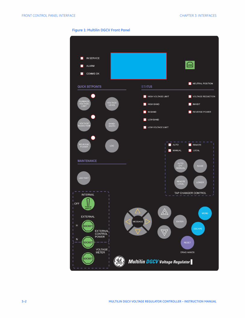
The Multilin DGCV Voltage Regulator front panel provides easy navigation using full keypad pushbuttons, conveniently located tap changer control pushbuttons, quick access to setpoints, regulation transparency using LED indicators, and a 4 x 20 character Liquid Crystal Display. The front panel includes the following components:
3–2 MULTILIN DGCV VOLTAGE REGULATOR CONTROLLER – INSTRUCTION MANUAL
FRONT CONTROL PANEL INTERFACE CHAPTER 3: INTERFACES
Figure 1: Multilin DGCV Front Panel

CHAPTER 3: INTERFACES FRONT CONTROL PANEL INTERFACE
MULTILIN DGCV VOLTAGE REGULATOR CONTROLLER – INSTRUCTION MANUAL 3–3
Multilin DGCV STATUS LEDs: Three LEDs indicating the Multilin DGCV status: “In-Service”, “Alarm”, and (communications) “Comms OK” are placed in the upper left corner of the Multilin DGCV front panel.
VOLTAGE REGULATION LEDs
4 X 20 CHARACTER LCDThe Multilin DGCV has an LCD with 4 lines of 20 characters, that allows visibility under varied lighting conditions. When the keypad and the display are not being used, system information is displayed after a user-defined period of inactivity. Pressing the keypad when the screen shows the default display returns the display to the last available message before the default screen activated. Any VR control actions, as well as element operations, are displayed automatically, overriding any target message displayed at that time. The display and the navigation keypad are conveniently located to provide the user easy access to any settings, actual values, status, monitoring tools, or statistics. QUICK SETPOINTS PUSHBUTTONSThe Multilin DGCV is equipped with 6 pushbuttons for quick access to variety of settings. Pressing any of these pushbuttons invokes a settings menu on the display, that corresponds to the feature specified on the pushbutton. For the user’s convenience, some pushbuttons are equipped with LEDs that show whether or not the feature specified on the
IN SERVICE: The Multilin DGCV is operational and functioning properly when the “In-Service” LED shows green. The LED turns off upon detection of an internal firmware or hardware error. The product is not programmed when shipped, and the “In-Service” LED will not light upon power up. The LED will turn on green upon selecting the “Ready” setting under the S1 INSTALLATION/PRODUCT STATUS menu.
ALARM: The “Alarm” LED turns orange upon detection of either an internal firmware error, a hardware error, or upon ALARM conditions driven by the control of the tap changer such as “Unsuccessful Tap Change,” or “Incomplete Tap Sequence”.
COMMS OK: The communications LED, is a bi-colour LED, meaning that it will show green when the transmit/receive channels are set and the VR is communicating with another smart device or SCADA. This LED will turn orange if the communication channels – communication card failure, or communication channels - are not working properly.
NEUTRAL POSITION: The “Neutral Position” LED turns green when the tap changer moves the lead to the neutral tap of the tapped winding.
IN BAND: The “IN BAND” LED turns green when the measured voltage is within the programmed voltage bandwith.
HIGH (LOW) BAND: The “HIGH BAND” or the “LOW BAND” LED turns orange if the measured load voltage is “out of band,” such as being above the programmed high band voltage level, or below the programmed low band voltage, respectively.
HIGH (LOW) VOLTAGE LIMIT:
The “HIGH VOLTAGE LIMIT” and “LOW VOLTAGE LIMIT” LEDs turn orange, when the measured load voltage is either above or below the user programmed voltage runback limits, respectively, and VOLT RUNBACK LIMITS setpoint is enabled. Upon such conditions, the voltage regulator issues a tap change command to the tap changer without any time delay.
VOLTAGE REDUCTION: This LED shows orange when any of the three voltage reduction stages has been activated.
AUTO INHIBIT: This LED shows orange, when any of the inhibiting elements has been activated upon triggering any of its programmed settings.
REVERSE POWER: Тhe “REVERSE POWER” LED turns orange when the Voltage Regulator detects reverse power in excess of the programmed reverse power setting for the specified time delay.
3–4 MULTILIN DGCV VOLTAGE REGULATOR CONTROLLER – INSTRUCTION MANUAL
FRONT CONTROL PANEL INTERFACE CHAPTER 3: INTERFACES
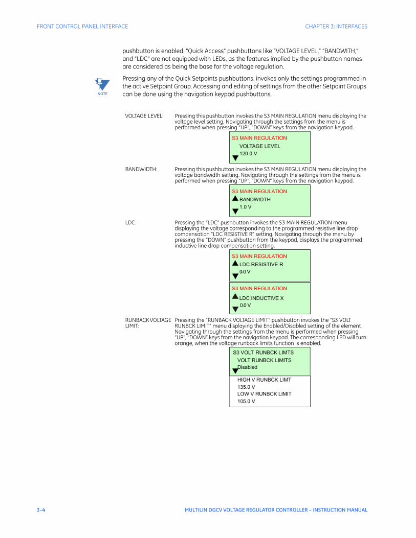
pushbutton is enabled. "Quick Access" pushbuttons like “VOLTAGE LEVEL,” “BANDWITH,” and “LDC” are not equipped with LEDs, as the features implied by the pushbutton names are considered as being the base for the voltage regulation.
NOTE
NOTE: Pressing any of the Quick Setpoints pushbuttons, invokes only the settings programmed in the active Setpoint Group. Accessing and editing of settings from the other Setpoint Groups can be done using the navigation keypad pushbuttons.
VOLTAGE LEVEL: Pressing this pushbutton invokes the S3 MAIN REGULATION menu displaying the voltage level setting. Navigating through the settings from the menu is performed when pressing “UP”, “DOWN” keys from the navigation keypad.
BANDWIDTH: Pressing this pushbutton invokes the S3 MAIN REGULATION menu displaying the voltage bandwidth setting. Navigating through the settings from the menu is performed when pressing “UP”, “DOWN” keys from the navigation keypad.
LDC: Pressing the “LDC" pushbutton invokes the S3 MAIN REGULATION menu displaying the voltage corresponding to the programmed resistive line drop compensation “LDC RESISTIVE R” setting. Navigating through the menu by pressing the “DOWN” pushbutton from the keypad, displays the programmed inductive line drop compensation setting.
RUNBACK VOLTAGE LIMIT:
Pressing the “RUNBACK VOLTAGE LIMIT” pushbutton invokes the “S3 VOLT RUNBCK LIMIT” menu displaying the Enabled/Disabled setting of the element. Navigating through the settings from the menu is performed when pressing “UP”, “DOWN” keys from the navigation keypad. The corresponding LED will turn orange, when the voltage runback limits function is enabled.
CHAPTER 3: INTERFACES FRONT CONTROL PANEL INTERFACE
MULTILIN DGCV VOLTAGE REGULATOR CONTROLLER – INSTRUCTION MANUAL 3–5
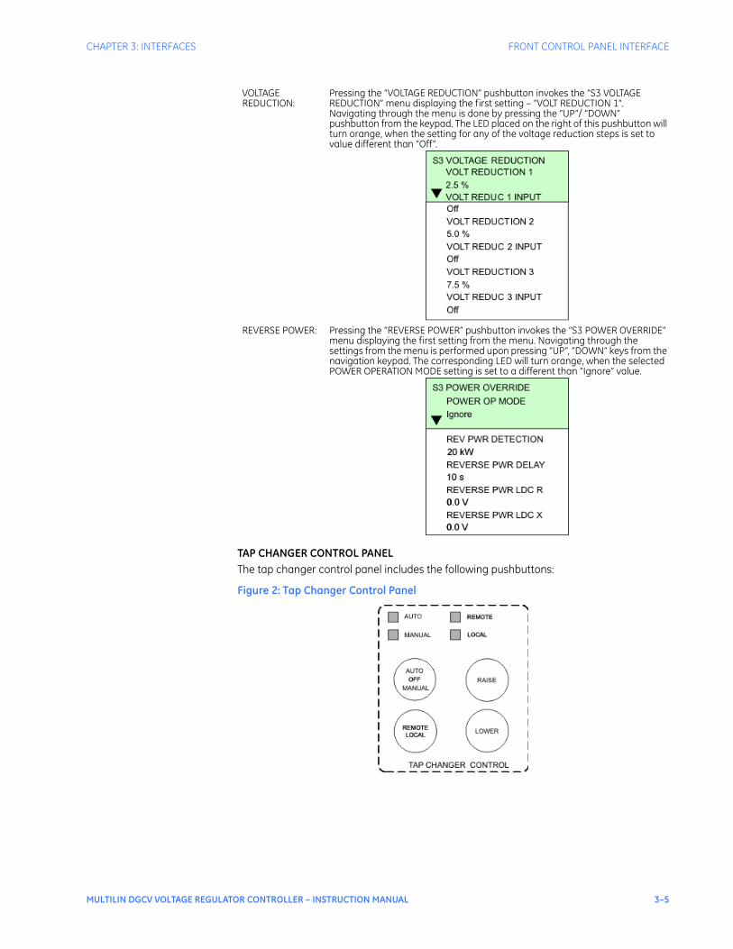
TAP CHANGER CONTROL PANELThe tap changer control panel includes the following pushbuttons:
Figure 2: Tap Changer Control Panel
VOLTAGE REDUCTION:
Pressing the “VOLTAGE REDUCTION” pushbutton invokes the “S3 VOLTAGE REDUCTION” menu displaying the first setting – “VOLT REDUCTION 1”. Navigating through the menu is done by pressing the “UP”/ “DOWN” pushbutton from the keypad. The LED placed on the right of this pushbutton will turn orange, when the setting for any of the voltage reduction steps is set to value different than “Off”.
REVERSE POWER: Pressing the “REVERSE POWER” pushbutton invokes the “S3 POWER OVERRIDE” menu displaying the first setting from the menu. Navigating through the settings from the menu is performed upon pressing “UP”, “DOWN” keys from the navigation keypad. The corresponding LED will turn orange, when the selected POWER OPERATION MODE setting is set to a different than “Ignore” value.
3–6 MULTILIN DGCV VOLTAGE REGULATOR CONTROLLER – INSTRUCTION MANUAL
FRONT CONTROL PANEL INTERFACE CHAPTER 3: INTERFACES
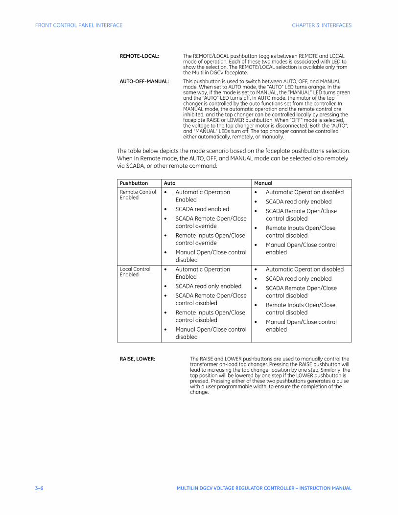
The table below depicts the mode scenario based on the faceplate pushbuttons selection. When In Remote mode, the AUTO, OFF, and MANUAL mode can be selected also remotely via SCADA, or other remote command:
REMOTE-LOCAL: The REMOTE/LOCAL pushbutton toggles between REMOTE and LOCAL mode of operation. Each of these two modes is associated with LED to show the selection. The REMOTE/LOCAL selection is available only from the Multilin DGCV faceplate.
AUTO-OFF-MANUAL: This pushbutton is used to switch between AUTO, OFF, and MANUAL mode. When set to AUTO mode, the “AUTO” LED turns orange. In the same way, if the mode is set to MANUAL, the “MANUAL” LED turns green and the “AUTO” LED turns off. In AUTO mode, the motor of the tap changer is controlled by the auto functions set from the controller. In MANUAL mode, the automatic operation and the remote control are inhibited, and the tap changer can be controlled locally by pressing the faceplate RAISE or LOWER pushbutton. When “OFF” mode is selected, the voltage to the tap changer motor is disconnected. Both the “AUTO”, and “MANUAL” LEDs turn off. The tap changer cannot be controlled either automatically, remotely, or manually.
Pushbutton Auto Manual
Remote Control Enabled
• Automatic Operation Enabled
• SCADA read enabled
• SCADA Remote Open/Close control override
• Remote Inputs Open/Close control override
• Manual Open/Close control disabled
• Automatic Operation disabled
• SCADA read only enabled
• SCADA Remote Open/Close control disabled
• Remote Inputs Open/Close control disabled
• Manual Open/Close control enabled
Local Control Enabled
• Automatic Operation Enabled
• SCADA read only enabled
• SCADA Remote Open/Close control disabled
• Remote Inputs Open/Close control disabled
• Manual Open/Close control disabled
• Automatic Operation disabled
• SCADA read only enabled
• SCADA Remote Open/Close control disabled
• Remote Inputs Open/Close control disabled
• Manual Open/Close control enabled
RAISE, LOWER: The RAISE and LOWER pushbuttons are used to manually control the transformer on-load tap changer. Pressing the RAISE pushbutton will lead to increasing the tap changer position by one step. Similarly, the tap position will be lowered by one step if the LOWER pushbutton is pressed. Pressing either of these two pushbuttons generates a pulse with a user programmable width, to ensure the completion of the change.

CHAPTER 3: INTERFACES FRONT CONTROL PANEL INTERFACE
MULTILIN DGCV VOLTAGE REGULATOR CONTROLLER – INSTRUCTION MANUAL 3–7
EXTERNAL POWER
Figure 3: External Power Control panel
The Multilin DGCV faceplate is equipped with a three-state switch for selection of Internal or External voltage. With the switch in the External position, the sensing and motor power circuits are connected to the external power binding post on the front panel. The unit can be tested using a 120 V RMS source with correct polarity applied to these terminals. Testing of the regulator can be accomplished by adjusting the amplitude of the external source. The switch disconnects all power from the unit if switched to External power with no power source applied to the front panel voltage terminals. The External Control Power binding posts allow application of a 120 V RMS nominal voltage to the unit for test purposes.The binding posts designated as VOLTAGE METER allow reading of the input voltage for calibration purposes.
Working with the KeypadThe display messages are organized into a Main Menu, pages, and sub-pages. There are four main menus labeled Actual Values, Quick Setup, Setpoints, and Maintenance. Pressing the MENU key followed by the MESSAGE key scrolls through the four Main Menu headers, which appear in sequence as follows:
Figure 4: The four Main Menu headers
Pressing the MESSAGE ► key or the ENTER key from these Main Menu pages will display the corresponding menu Page. Use the MESSAGE ▲ and MESSAGE ▼ keys to scroll through the Page headers.
█ ACTUAL VALUES
QUICK SETUP
SETPOINTS
MAINTENANCE
3–8 MULTILIN DGCV VOLTAGE REGULATOR CONTROLLER – INSTRUCTION MANUAL
FRONT CONTROL PANEL INTERFACE CHAPTER 3: INTERFACES
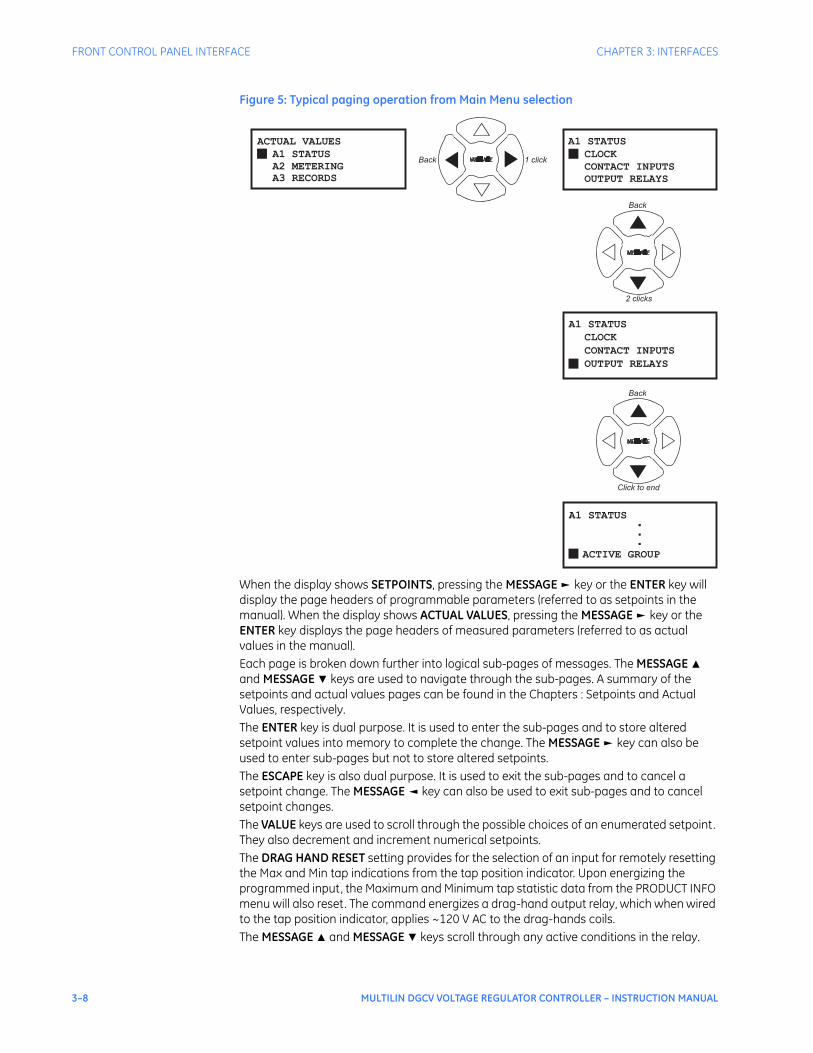
Figure 5: Typical paging operation from Main Menu selection
When the display shows SETPOINTS, pressing the MESSAGE ► key or the ENTER key will display the page headers of programmable parameters (referred to as setpoints in the manual). When the display shows ACTUAL VALUES, pressing the MESSAGE ► key or the ENTER key displays the page headers of measured parameters (referred to as actual values in the manual). Each page is broken down further into logical sub-pages of messages. The MESSAGE ▲ and MESSAGE ▼ keys are used to navigate through the sub-pages. A summary of the setpoints and actual values pages can be found in the Chapters : Setpoints and Actual Values, respectively.The ENTER key is dual purpose. It is used to enter the sub-pages and to store altered setpoint values into memory to complete the change. The MESSAGE ► key can also be used to enter sub-pages but not to store altered setpoints.The ESCAPE key is also dual purpose. It is used to exit the sub-pages and to cancel a setpoint change. The MESSAGE ◄ key can also be used to exit sub-pages and to cancel setpoint changes.The VALUE keys are used to scroll through the possible choices of an enumerated setpoint. They also decrement and increment numerical setpoints. The DRAG HAND RESET setting provides for the selection of an input for remotely resetting the Max and Min tap indications from the tap position indicator. Upon energizing the programmed input, the Maximum and Minimum tap statistic data from the PRODUCT INFO menu will also reset. The command energizes a drag-hand output relay, which when wired to the tap position indicator, applies ~120 V AC to the drag-hands coils.The MESSAGE ▲ and MESSAGE ▼ keys scroll through any active conditions in the relay.
█ CLOCK
A1 STATUS
CONTACT INPUTS
OUTPUT RELAYS
█
ACTUAL VALUES
A1 STATUS
A2 METERING
A3 RECORDS
█
CONTACT INPUTS
A1 STATUS
OUTPUT RELAYS
CLOCK
█
A1 STATUS
ACTIVE GROUP
.
.
.
2 clicks
▽
△
▶
▶
▼
◁ ▷
▼
▼
◁ ▷
Click to end
▼Back
Back
Back 1 click
CHAPTER 3: INTERFACES FRONT CONTROL PANEL INTERFACE
MULTILIN DGCV VOLTAGE REGULATOR CONTROLLER – INSTRUCTION MANUAL 3–9
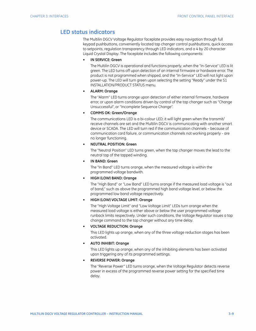
LED status indicatorsThe Multilin DGCV Voltage Regulator faceplate provides easy navigation through full keypad pushbuttons, conveniently located tap changer control pushbuttons, quick access to setpoints, regulation transparency through LED indicators, and a 4 by 20 character Liquid Crystal Display. The faceplate includes the following components:
• IN SERVICE: Green
The Multilin DGCV is operational and functions properly, when the “In-Service” LED is lit green. The LED turns off upon detection of an internal firmware or hardware error. The product is not programmed when shipped, and the “In-Service” LED will not light upon power-up. The LED will turn green upon selecting the setting “Ready” under the S1 INSTALLATION/PRODUCT STATUS menu.
• ALARM: Orange
The “Alarm” LED turns orange upon detection of either internal firmware, hardware error, or upon alarm conditions driven by control of the tap changer such as “Change Unsuccessful”, or “Incomplete Sequence Change”.
• COMMS OK: Green/Orange
The communications LED is a bi-colour LED; it will light green when the transmit/receive channels are set and the Multilin DGCV is communicating with another smart device or SCADA. The LED will turn red if the communication channels – because of communication card failure, or communication channels not working properly - are no longer functioning.
• NEUTRAL POSITION: Green
The "Neutral Position” LED turns green, when the tap changer moves the lead to the neutral tap of the tapped winding.
• IN BAND: Green
The "In Band” LED turns orange, when the measured voltage is within the programmed voltage bandwith.
• HIGH (LOW) BAND: Orange
The “High Band” or “Low Band” LED turns orange if the measured load voltage is “out of band,” such as above the programmed high band voltage level, or below the programmed low band voltage respectively.
• HIGH (LOW) VOLTAGE LIMIT: Orange
The “High Voltage Limit” and “Low Voltage Limit” LEDs turn orange when the measured load voltage is either above or below the user programmed voltage runback limits respectively. Under such conditions, the Voltage Regulator issues a tap change command to the tap changer without any time delay.
• VOLTAGE REDUCTION: Orange
This LED lights up orange, when any of the three voltage reduction stages has been activated.
• AUTO INHIBIT: Orange
This LED lights up orange, when any of the inhibiting elements has been activated upon triggering any of its programmed settings.
• REVERSE POWER: Orange
Тhe “Reverse Power” LED turns orange, when the Voltage Regulator detects reverse power in excess of the programmed reverse power setting for the specified time delay.
3–10 MULTILIN DGCV VOLTAGE REGULATOR CONTROLLER – INSTRUCTION MANUAL
SOFTWARE SETUP CHAPTER 3: INTERFACES
Software setup
EnerVista Multilin DGCV Setup SoftwareAlthough settings can be entered manually using the control panel keys, a PC can be used to download setpoints through the communications port. The software is available from GE Multilin to make this as convenient as possible. With running, it is possible to:
• Program and modify settings
• Load and save setting files to and from a disk
• Read actual values
• Monitor status
• Read pre-trip data and event records
• Get help on any topic
• Upgrade the firmware
The software allows immediate access to all features with easy to use pull down menus in the familiar Windows environment. This section provides the necessary information to install , upgrade the relay firmware, and write and edit setting files.The software can run without a connected to the computer. In this case, settings may be saved to a file for future use. If a is connected to a PC and communications are enabled, the can be programmed from the setting screens. In addition, measured values, status and trip messages can be displayed with the actual value screens.
Hardware andsoftware
requirements
The following requirements must be met for the software.
• Microsoft Windows™ 7 / XP is installed and running properly.
• At least 100 MB of hard disk space is available.
• At least 256 MB of RAM is installed.
The software can be installed from either the GE EnerVista CD or the GE Multilin website at http://www.GEmultilin.com.
Installing theEnerVista DGCVSetup software
After ensuring the minimum requirements indicated earlier, use the following procedure to install the EnerVista DGCV Setup software from the enclosed GE EnerVista CD.
1. Insert the GE EnerVista CD into your CD-ROM drive.
2. Click the Install Now button and follow the installation instructions to install the no-charge EnerVista software on the local PC.
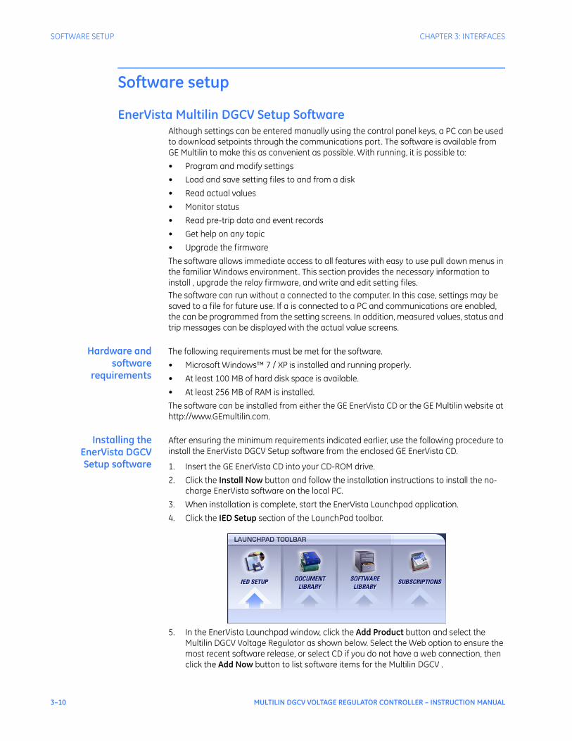
3. When installation is complete, start the EnerVista Launchpad application.
4. Click the IED Setup section of the LaunchPad toolbar.
5. In the EnerVista Launchpad window, click the Add Product button and select the Multilin DGCV Voltage Regulator as shown below. Select the Web option to ensure the most recent software release, or select CD if you do not have a web connection, then click the Add Now button to list software items for the Multilin DGCV .

CHAPTER 3: INTERFACES SOFTWARE SETUP
MULTILIN DGCV VOLTAGE REGULATOR CONTROLLER – INSTRUCTION MANUAL 3–11
6. EnerVista Launchpad will obtain the latest installation software from the Web or CD and automatically start the installation process. A status window with a progress bar will be shown during the downloading process.
7. Select the complete path, including the new directory name, where the EnerVista DGCV Setup software will be installed.
8. Click on Next to begin the installation. The files will be installed in the directory indicated, the USB driver will be loaded into the computer, and the installation program will automatically create icons and add EnerVista DGCV Setup software to the Windows start menu.
9. The Multilin DGCV device will be added to the list of installed IEDs in the EnerVista Launchpad window, as shown below.

3–12 MULTILIN DGCV VOLTAGE REGULATOR CONTROLLER – INSTRUCTION MANUAL
SOFTWARE SETUP CHAPTER 3: INTERFACES
If you are going to communicate from your computer to the Relay using the USB port:
10. Plug the USB cable into the USB port on the Relay then into the USB port on your computer.
11. Launch EnerVista DGCV Setup from LaunchPad.
12. In EnerVista > Device Setup:

CHAPTER 3: INTERFACES SOFTWARE SETUP
MULTILIN DGCV VOLTAGE REGULATOR CONTROLLER – INSTRUCTION MANUAL 3–13
13. Select USB as the Interface type.
14. Select Multilin DGCV as the USB device.
Connecting EnerVista DGCV Setup to the device
Configuring serialcommunications
Before starting, verify that the cable is properly connected to either the USB port on the front panel of the device (for USB communications) or to the RS485 terminals on the back of the device (for RS485 communications). This example demonstrates an USB connection. For RS485 communications, the GE Multilin F485 converter will be required. Refer to the F485 manual for additional details.
1. Install and start the latest version of the software (available from the GE Multilin web site). See the previous section for the installation procedure.
2. Click on the Device Setup button to open the Device Setup window and click the Add Site button to define a new site.
3. Enter the desired site name in the "Site Name" field. If desired, a short description of the site can also be entered. In this example, we will use “Substation 1” as the site name.
4. The new site will appear in the upper-left list in the window.
5. Click the Add Device button to define the new device.
6. Enter the desired name in the "Device Name" field and a description (optional) of the device.
7. Select “Serial” from the Interface drop-down list.

3–14 MULTILIN DGCV VOLTAGE REGULATOR CONTROLLER – INSTRUCTION MANUAL
SOFTWARE SETUP CHAPTER 3: INTERFACES
8. Click the Read Order Code button to connect to the device and upload the order code.
9. Click OK when the relay order code has been received. The new device will be added to the Site List window (or Online window) located in the top left corner of the main window.
The Site Device has now been configured for USB communications. Proceed to Connecting to the Multilin DGCV below, to begin communications.
Using the QuickConnect feature
The Quick Connect button can be used to establish a fast connection through the front panel USB port of a DGC device. The following window will appear when the QuickConnect button is pressed:
As indicated by the window, the "Quick Connect" feature can quickly connect the software to a front port if a USB is selected in the interface drop-down list. Select a device and press the Connect button. When connected, a new Site called “Quick Connect” will appear in the Site List window.
CHAPTER 3: INTERFACES SOFTWARE SETUP
MULTILIN DGCV VOLTAGE REGULATOR CONTROLLER – INSTRUCTION MANUAL 3–15
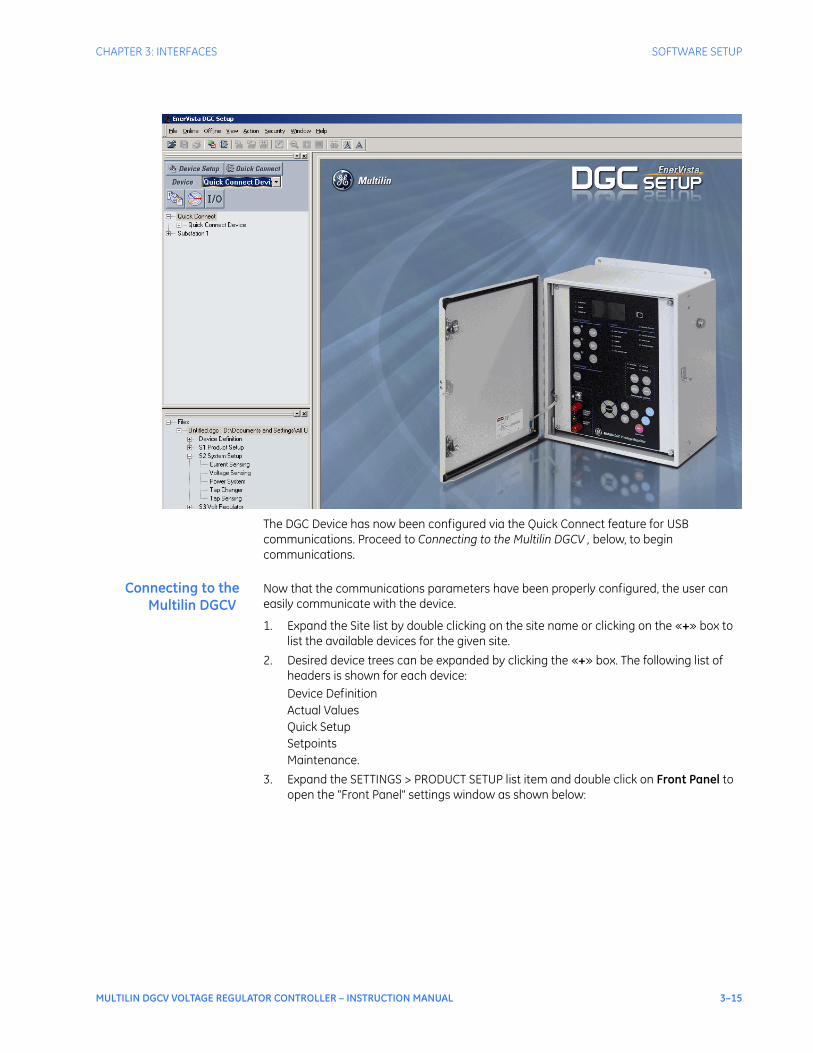
The DGC Device has now been configured via the Quick Connect feature for USB communications. Proceed to Connecting to the Multilin DGCV , below, to begin communications.
Connecting to theMultilin DGCV
Now that the communications parameters have been properly configured, the user can easily communicate with the device.
1. Expand the Site list by double clicking on the site name or clicking on the «+» box to list the available devices for the given site.
2. Desired device trees can be expanded by clicking the «+» box. The following list of headers is shown for each device:Device DefinitionActual ValuesQuick SetupSetpointsMaintenance.
3. Expand the SETTINGS > PRODUCT SETUP list item and double click on Front Panel to open the "Front Panel" settings window as shown below:

3–16 MULTILIN DGCV VOLTAGE REGULATOR CONTROLLER – INSTRUCTION MANUAL
SOFTWARE SETUP CHAPTER 3: INTERFACES
4. The "Front Panel" settings window will open with a corresponding status indicator on the lower left of the EnerVista DGCV Setup window.
5. If the status indicator is red, verify that the serial or USB cable is properly connected to the relay, and that the device has been properly configured for communications (steps described earlier).
The "Front Panel" settings can now be edited, printed, or changed. Other settings and command windows can be displayed and edited in a similar manner. "Actual Values" windows are also available for display. These windows can be arranged, and resized at will.
Working with settings and settings files
Engaging a device The EnerVista DGCV Setup software may be used in on-line mode (relay connected) to directly communicate with a DGC device. Communicating devices are organized and grouped by communication interfaces and into sites. Sites may contain any number of devices selected from the product series.
CHAPTER 3: INTERFACES SOFTWARE SETUP
MULTILIN DGCV VOLTAGE REGULATOR CONTROLLER – INSTRUCTION MANUAL 3–17
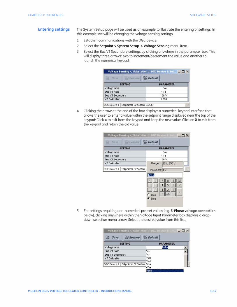
Entering settings The System Setup page will be used as an example to illustrate the entering of settings. In this example, we will be changing the voltage sensing settings.
1. Establish communications with the DGC device.
2. Select the Setpoint > System Setup > Voltage Sensing menu item.
3. Select the Bus VT Secondary settings by clicking anywhere in the parameter box. This will display three arrows: two to increment/decrement the value and another to launch the numerical keypad.
4. Clicking the arrow at the end of the box displays a numerical keypad interface that allows the user to enter a value within the setpoint range displayed near the top of the keypad: Click = to exit from the keypad and keep the new value. Click on X to exit from the keypad and retain the old value.
5. For settings requiring non-numerical pre-set values (e.g. 3-Phase voltage connection below), clicking anywhere within the Voltage Input Parameter box displays a drop-down selection menu arrow. Select the desired value from this list.
3–18 MULTILIN DGCV VOLTAGE REGULATOR CONTROLLER – INSTRUCTION MANUAL
SOFTWARE SETUP CHAPTER 3: INTERFACES
6. For settings requiring an alphanumeric text string (e.g. "relay name"), the value may be entered directly within the settings Parameter box.
7. In the Setpoint > System Setup > Voltage Sensing dialog box, click on Save to save the values into the . Click YES to accept any changes and exit the window. Click Restore to retain previous values. Click Default to restore Default values.
File support Opening any file will automatically launch the application or provide focus to the already opened application. If the file is a settings file (has a ‘DGC’ extension) which had been removed from the Settings List tree menu, it will be added back to the Settings List tree.New files will be automatically added to the tree.
Using settings files The software interface supports three ways of handling changes to Multilin DGCV settings:
• In off-line mode (DGC disconnected) to create or edit DGC settings files for later download to communicating DGC devices.
• Directly modifying DGC settings while connected to a communicating DGC device, then saving the settings when complete.
• Creating/editing settings files while connected to a communicating DGC device, then saving them to the device when complete.
Settings files are organized on the basis of file names assigned by the user. A settings file contains data pertaining to the following types of DGC settings:
• Device Definition
• DGC Setup
• System Setup
• Protection
• Control
• Inputs/Outputs
Factory default values are supplied and can be restored after any changes.The displays DGC settings with the same hierarchy as the front panel display.
Downloading andsaving settings files
Settings must be saved to a file on the local PC before performing any firmware upgrades. Saving settings is also highly recommended before making any settings changes or creating new settings files.The settings files in the window are accessed in the Files Window. Use the following procedure to download and save settings files to a local PC.
1. Ensure that the site and corresponding device(s) have been properly defined and configured as shown in Connecting to the Multilin DGCV , above.
2. Select the desired device from the site list.
3. Select the Online > Read Device Settings from Device menu item, or right-click on the device and select Read Device Settings to obtain settings information from the device.
4. After a few seconds of data retrieval, the software will request the name and destination path of the settings file. The corresponding file extension will be automatically assigned. Press Receive to complete the process. A new entry will be added to the tree, in the File pane, showing path and file name for the setting file.
Adding settings filesto the environment
The software provides the capability to review and manage a large group of settings files. Use the following procedure to add an existing file to the list.
CHAPTER 3: INTERFACES SOFTWARE SETUP
MULTILIN DGCV VOLTAGE REGULATOR CONTROLLER – INSTRUCTION MANUAL 3–19
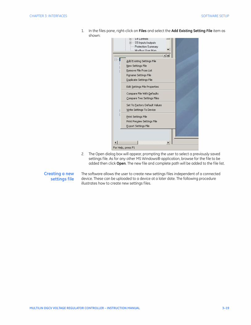
1. In the files pane, right-click on Files and select the Add Existing Setting File item as shown:
2. The Open dialog box will appear, prompting the user to select a previously saved settings file. As for any other MS Windows® application, browse for the file to be added then click Open. The new file and complete path will be added to the file list.
Creating a newsettings file
The software allows the user to create new settings files independent of a connected device. These can be uploaded to a device at a later date. The following procedure illustrates how to create new settings files.

3–20 MULTILIN DGCV VOLTAGE REGULATOR CONTROLLER – INSTRUCTION MANUAL
SOFTWARE SETUP CHAPTER 3: INTERFACES
1. In the File pane, right click on File and select the New Settings File item. The following box will appear, allowing for the configuration of the settings file for the correct firmware version. It is important to define the correct firmware version to ensure that settings not available in a particular version are not downloaded into the device.
2. Select the Firmware Version, and Order Code options for the new settings file.
3. For future reference, enter some useful information in the Description box to facilitate the identification of the device and the purpose of the file.
4. To select a file name and path for the new file, click the button beside the File Name box.
5. Select the file name and path to store the file, or select any displayed file name to replace an existing file. All setpoint files should have the extension ‘DGC’ (for example, ‘feeder1.DGC’).
6. Click OK to complete the process. Once this step is completed, the new file, with a complete path, will be added to the EnerVista DGCV Setup software environment.
Upgrading settingsfiles to a new revision
It is often necessary to upgrade the revision for a previously saved settings file after the firmware has been upgraded. This is illustrated in the following procedure:
1. Establish communications with the relay.
2. Select the Maintenance > M1 Relay Info menu item and record the Firmware Revision.
3. Load the settings file to be upgraded into the EnerVista DGCV Setup environment as described in the section, Adding Settings Files to the Environment.
4. In the File pane, select the saved settings file.
5. From the main window menu bar, select the Offline > Edit Settings File Properties menu item and note the File Version of the settings file. If this version is different from the Firmware Revision noted in step 2, select a New File Version that matches the Firmware Revision from the pull-down menu.

CHAPTER 3: INTERFACES SOFTWARE SETUP
MULTILIN DGCV VOLTAGE REGULATOR CONTROLLER – INSTRUCTION MANUAL 3–21
6. For example, if the firmware revision is 1.20) and the current settings file revision is 1.10, change the setpoint file revision to “1.2x”.
7. Enter any special comments about the settings file in the "Description" field.
8. Select the desired firmware version from the "New File Version" field.
9. When complete, click OK to convert the settings file to the desired revision. See Loading Settings from a File below, for instructions on loading this settings file into the Multilin DGCV device.
Printing settings andactual values
The EnerVista DGCV Setup software allows the user to print partial or complete lists of settings and Actual Values. Use the following procedure to print a list of settings:
1. Select a previously saved settings file in the File pane or establish communications with a device.
2. From the main window, select the Offline > Export Settings File menu item.

3–22 MULTILIN DGCV VOLTAGE REGULATOR CONTROLLER – INSTRUCTION MANUAL
SOFTWARE SETUP CHAPTER 3: INTERFACES
3. The Print/Export Options dialog box will appear. Select Settings in the upper section and select either Include All Features (for a complete list) or Include Only Enabled Features (for a list of only those features which are currently used) in the filtering section and click OK.
4. The process for Offline > Print Preview Settings File is identical to the steps above.
5. Settings lists can be printed in the same manner by right clicking on the desired file (in the file list) or device (in the device list) and selecting the Print Device Information or Print Settings File options.
Printing actual valuesfrom a connected
device
A complete list of actual values can also be printed from a connected device with the following procedure:
1. Establish communications with the desired device.
2. From the main window, select the Online > Print Device Information menu item
3. The Print/Export Options dialog box will appear. Select Actual Values in the upper section and select either Include All Features (for a complete list) or Include Only Enabled Features (for a list of only those features which are currently used) in the filtering section and click OK.
Actual Values lists can be printed in the same manner by right clicking on the desired device (in the device list) and selecting the Print Device Information option
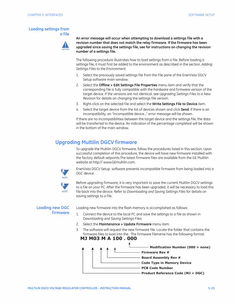
CHAPTER 3: INTERFACES SOFTWARE SETUP
MULTILIN DGCV VOLTAGE REGULATOR CONTROLLER – INSTRUCTION MANUAL 3–23
Loading settings froma file
CAUTION
CAUTION: An error message will occur when attempting to download a settings file with a revision number that does not match the relay firmware. If the firmware has been upgraded since saving the settings file, see for instructions on changing the revision number of a settings file.
The following procedure illustrates how to load settings from a file. Before loading a settings file, it must first be added to the environment as described in the section, Adding Settings Files to the Environment.
1. Select the previously saved settings file from the File pane of the EnerVista DGCV Setup software main window.
2. Select the Offline > Edit Settings File Properties menu item and verify that the corresponding file is fully compatible with the hardware and firmware version of the target device. If the versions are not identical, see Upgrading Settings Files to a New Revision for details on changing the settings file version.
3. Right-click on the selected file and select the Write Settings File to Device item.
4. Select the target device from the list of devices shown and click Send. If there is an incompatibility, an "Incompatible device..." error message will be shown.
If there are no incompatibilities between the target device and the settings file, the data will be transferred to the device. An indication of the percentage completed will be shown in the bottom of the main window.
Upgrading Multilin DGCV firmwareTo upgrade the Multilin DGCV firmware, follow the procedures listed in this section. Upon successful completion of this procedure, the device will have new firmware installed with the factory default setpoints.The latest firmware files are available from the GE Multilin website at http:// www.GEmultilin.com.
NOTE
NOTE: EnerVista DGCV Setup software prevents incompatible firmware from being loaded into a DGC device.
NOTE
NOTE: Before upgrading firmware, it is very important to save the current Multilin DGCV settings to a file on your PC. After the firmware has been upgraded, it will be necessary to load this file back into the device. Refer to Downloading and Saving Settings Files for details on saving settings to a file.
Loading new DGCfirmware
Loading new firmware into the flash memory is accomplished as follows:
1. Connect the device to the local PC and save the settings to a file as shown in Downloading and Saving Settings Files.
2. Select the Maintenance > Update Firmware menu item.
3. The software will request the new firmware file. Locate the folder that contains the firmware files to load into the . The firmware filename has the following format:
MJ M03 M A 100 . 000
Modification Number (000 = none)
Board Assembly Rev #
Code Type in Memory Device
PCB Code Number
Product Reference Code (MJ = DGC)
Firmware Rev #

3–24 MULTILIN DGCV VOLTAGE REGULATOR CONTROLLER – INSTRUCTION MANUAL
SOFTWARE SETUP CHAPTER 3: INTERFACES
4. EnerVista DGCV Setup software now prepares the to receive the new firmware file. The front panel will momentarily display "DGC BOOT PROGRAM Waiting for Message,” indicating that it is in upload mode.
5. While the file is being loaded into the device, a status box appears showing how much of the new firmware file has been transferred, and the upgrade status. The entire transfer process takes approximately 10 minutes.
6. The software will notify the user when the EnerVista DGCV Setup program has finished loading the file. Carefully read any displayed messages and click OK to return the main screen. Cycling power to the relay is recommended after a firmware upgrade.
After successfully updating the firmware, the device will not be in service and will require settings programming. To communicate with the relay, the communication settings may have to be manually reprogrammed.When communications are established, the saved setpoints must be reloaded back into the device. See Loading Settings from a File for details.Modbus addresses assigned to firmware modules, features, settings, and corresponding data items (i.e. default values, min/max values, data type, and item size) may change slightly from version to version of the firmware.Addresses are rearranged when new features are added or existing features are enhanced or modified.
Advanced EnerVista DGCV Setup features
Event records The EnerVista DGCV Setup software can be used to capture events from the device at the instance of a pickup, trip, alarm, or other condition.
• With EnerVista DGCV Setup software running and communications established, select the Actual Values > A3 Records > Event Records menu item to open the Event Records Viewer window.

CHAPTER 3: INTERFACES SOFTWARE SETUP
MULTILIN DGCV VOLTAGE REGULATOR CONTROLLER – INSTRUCTION MANUAL 3–25
• Click on the Save Events button to save the selected events to the local PC.
Data logger The data logger feature is used to sample and record up to ten actual values at a selectable interval. The datalogger can be run with Continuous mode Enabled, which will continuously record samples until stopped by the user; or with Continuous mode Disabled, which will trigger the datalog once without overwriting previous data.Viewing and saving of the Datalogger is performed as follows:
1. With running and communications established, select the A3 Records > Data Logger menu item to open the datalog setup window:

3–26 MULTILIN DGCV VOLTAGE REGULATOR CONTROLLER – INSTRUCTION MANUAL
SOFTWARE SETUP CHAPTER 3: INTERFACES
2. If Continuous mode is enabled, click on Stop to stop the datalog
3. Click on the Save to File button to save the datalog to the local PC. A new window will appear requesting for file name and path.
4. One file is saved as a COMTRADE file, with the extension ‘CFG’. The other file is a DAT file, required by the COMTRADE file for proper display of data.
5. To view a previously saved COMTRADE file, click the Open button and select the corresponding COMTRADE file.
6. To view the datalog, click the Launch Viewer button. A detailed Datalog window will appear as shown below.

CHAPTER 3: INTERFACES SOFTWARE SETUP
MULTILIN DGCV VOLTAGE REGULATOR CONTROLLER – INSTRUCTION MANUAL 3–27
7. The datalog can be set to capture another buffer by clicking on Run (when Continuous mode is enabled), or by clicking on Release (when Continuous mode is disabled).
Password security Password security is an optional feature of the Multilin DGCV which can be setup using the EnerVista DGCV Setup software. The password system has been designed to facilitate a hierarchy for centralized management. This is accomplished through a Master level access password which can be used for resetting lower level access passwords and higher level privileged operations. In cases where operational security is required as well as a central administrative authority then the use of the password system is highly encouraged. The feature robustness of this system requires it to be managed exclusively through the EnerVista setup software. This section describes how to perform the initial setup. For more details on the password security feature, refer to Chapter 6 - Password Security.
1. Multilin DGCV devices shipped from the factory are initially set with security disabled. If the password security feature is to be used, the user must first change the Master Reset Password from the initial Null setting. This can be done only over communications, not from the front panel keypad. The new Master Reset Password must be 8 to 10 characters in length, and must have minimum 2 letters and 2
Display graph values
at the corresponding
cursor line. Cursor
lines are identified by
their colors.
CURSOR
LINES
To move lines locate the mouse pointer
over the cursor line then click and drag
the cursor to the new location.
DELTA
Indicates time difference
between the two cursor lines
TRIGGER LINE
Indicates the
point in time for
the trigger
FILE NAME
Indicates the
file name and
complete path
(if saved)
TRIGGER TIME & DATE
Display the time & date of the
Trigger
VECTOR DISPLAY SELECT
Click here to open a new graph
to display vectors
CURSOR LINE POSITION
Indicate the cursor line position
in time with respect to the
trigger time
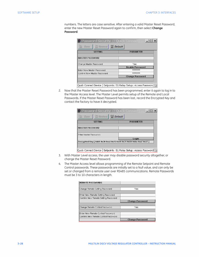
3–28 MULTILIN DGCV VOLTAGE REGULATOR CONTROLLER – INSTRUCTION MANUAL
SOFTWARE SETUP CHAPTER 3: INTERFACES
numbers. The letters are case sensitive. After entering a valid Master Reset Password, enter the new Master Reset Password again to confirm, then select Change Password.
2. Now that the Master Reset Password has been programmed, enter it again to log in to the Master Access level. The Master Level permits setup of the Remote and Local Passwords. If the Master Reset Password has been lost, record the Encrypted Key and contact the factory to have it decrypted.
3. With Master Level access, the user may disable password security altogether, or change the Master Reset Password.
4. The Master Access level allows programming of the Remote Setpoint and Remote Control passwords. These passwords are initially set to a Null value, and can only be set or changed from a remote user over RS485 communications. Remote Passwords must be 3 to 10 characters in length.
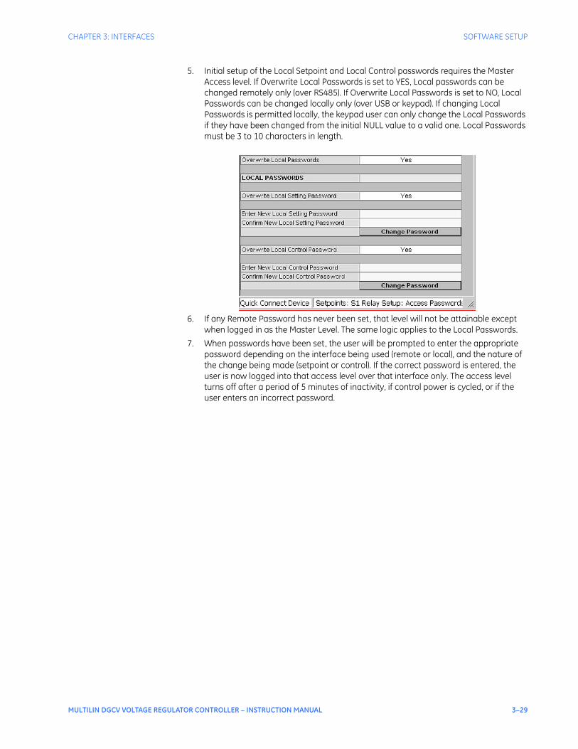
CHAPTER 3: INTERFACES SOFTWARE SETUP
MULTILIN DGCV VOLTAGE REGULATOR CONTROLLER – INSTRUCTION MANUAL 3–29
5. Initial setup of the Local Setpoint and Local Control passwords requires the Master Access level. If Overwrite Local Passwords is set to YES, Local passwords can be changed remotely only (over RS485). If Overwrite Local Passwords is set to NO, Local Passwords can be changed locally only (over USB or keypad). If changing Local Passwords is permitted locally, the keypad user can only change the Local Passwords if they have been changed from the initial NULL value to a valid one. Local Passwords must be 3 to 10 characters in length.
6. If any Remote Password has never been set, that level will not be attainable except when logged in as the Master Level. The same logic applies to the Local Passwords.
7. When passwords have been set, the user will be prompted to enter the appropriate password depending on the interface being used (remote or local), and the nature of the change being made (setpoint or control). If the correct password is entered, the user is now logged into that access level over that interface only. The access level turns off after a period of 5 minutes of inactivity, if control power is cycled, or if the user enters an incorrect password.

3–30 MULTILIN DGCV VOLTAGE REGULATOR CONTROLLER – INSTRUCTION MANUAL
SOFTWARE SETUP CHAPTER 3: INTERFACES

MULTILIN DGCV VOLTAGE REGULATOR CONTROLLER – INSTRUCTION MANUAL 4–1
Multilin DGCV Voltage Regulator Controller
Chapter 4: Actual values
Digital Energy
Actual values
A2 METERING
CURRENT
VOLTAGE
POWER
FREQUENCY
THD
HARMONICS
▼
A1 STATUS
CLOCK
CONTACT INPUTS
OUTPUT RELAYS
VIRTUAL INPUTS
VIRTUAL OUTPUTS
C. INPUTS SUMMARY
OUT RELAYS SUMMARY
FLEXLOGIC SUMMARY
TAP POSITION
ACTIVE GROUP
▼
ACTUAL VALUES
A1 STATUS
A2 METERING
A3 RECORDS
A4 TARGET MESSAGES
891961.cdr
A3 RECORDS
EVENT RECORDS
DATA LOGGER
CLEAR EVENT REC
CLEAR DATA LOGGER
▼
A4 TARGET MESSAGES
Target Message 1
State:
Target Message 2
State:
...
▼
▼

4–2 MULTILIN DGCV VOLTAGE REGULATOR CONTROLLER – INSTRUCTION MANUAL
A1 STATUS CHAPTER 4: ACTUAL VALUES
A1 Status
The main Status Menu is shown below:
Figure 1: Status menu
A1 CONTACT INPUTS
CONTACT INPUT 1
CONTACT INPUT 2
...
CONTACT INPUT n
▼
A1 CLOCK
CURRENT DATE
CURRENT TIME
▼
A1 STATUS
CLOCK
CONTACT INPUTS
OUTPUT RELAYS
VIRTUAL INPUTS
VIRTUAL OUTPUTS
C. INPUTS SUMMARY
OUT RELAYS SUMMARY
FLEXLOGIC SUMMARY
TAP POSITION
ACTIVE GROUP
▼
891963.cdr
A1 OUTPUT RELAYS
OUTPUT RELAY 1
...
▼
OUTPUT RELAY 2
OUTPUT RELAY 3
OUTPUT RELAY x
A1 FLEXLOGIC SUMMARY
FLEXLOGIC STATUS
FLEX LINES USED
▼
A1 VIRTUAL INPUTS
1
2
...
32
VIRTUAL INPUT
VIRTUAL INPUT
VIRTUAL INPUT
▼
A1 VIRTUAL OUTPUTS
1
2
...
32
VIRTUAL OUTPUT
VIRTUAL OUTPUT
VIRTUAL OUTPUT
▼
RLY 1 OFF RLY 5 OFF
RLY 2 OFF RLY 6 OFF
RLY 3 OFF RLY 7 OFF
RLY 4 OFF RLY 8 OFF
CI 1 OFF CI 5 OFF
CI 2 OFF CI 6 OFF
CI 3 OFF CI 7 OFF
CI 4 OFF CI 8 OFF
CI 9 OFF
CI 10 OFF
CI 11 OFF
CI 12 OFF
Contact Inputs Summary
Output Relays Summary
NOTE: # of outputs dependson ordercode
NOTE: # of inputs dependson ordercode
A1 TAP POSITION
TAP POSITION
A1 ACTIVE GROUP
ACTIVE GROUP
CHAPTER 4: ACTUAL VALUES A1 STATUS
MULTILIN DGCV VOLTAGE REGULATOR CONTROLLER – INSTRUCTION MANUAL 4–3
ClockPATH: ACTUAL VALUES > A1 STATUS > CLOCK
CURRENT DATEFeb 12 2009
Range: Date in format shown
Indicates today’s date.
CURRENT TIME09:17:12
Range: Time in format shown
Indicates the current time of day.
Contact inputsPATH: ACTUAL VALUES > A1 STATUS > CONTACT INPUTS
CONTACT INPUT 1 to 12OFF
Range: Off, On
Message displays the state of the contact input. The message “ON” indicates that the contact input is energized, and message “OFF” indicates a de-energized contact.
Output relaysPATH: ACTUAL VALUES > A1 STATUS > OUTPUT RELAYS
RAISE TAP (Output Relay #1)OFF
Range: Off, On
The “ON” state of Output Relay #1 (TRIP) shows that a TRIP command has been sent to the breaker.
LOWER TAP (Output Relay #2)OFF
Range: Off, On
The “ON” state of Output Relay #2 (CLOSE) shows that a close command has been sent to the breaker.
OUTPUT RELAY 3 to X (Auxiliary Output Relays)OFF
Range: Off, On

4–4 MULTILIN DGCV VOLTAGE REGULATOR CONTROLLER – INSTRUCTION MANUAL
A1 STATUS CHAPTER 4: ACTUAL VALUES
Virtual inputsThe state of all active virtual inputs is displayed here. PATH: ACTUAL VALUES > A1 STATUS > VIRTUAL INPUTS
VIRTUAL INPUTS 1 to 32OFF
Range: Off, On
Virtual outputsThe state of all active virtual outputs is displayed here. PATH: ACTUAL VALUES > A1 STATUS > VIRTUAL OUTPUTS
VIRTUAL OUTPUTS 1 to 32OFF
Range: Off, On
Contact inputs summaryC. INPUTS SUMMARY
The display shows a summary of the states of all contact inputs.
Output relays summaryPATH: ACTUAL VALUES > A1 STATUS > OUT RELAYS SUMMARY
OUTPUT RELAYS SUMMARY
This display shows a summary of the states of all output relays.
NOTE
NOTE: Output Relays #1 and #2 are the Raise Tap and Lower Tap relays respectively.
CI#1 OFF CI#7 OFF
CI#2 OFF CI#8 OFF
CI#3 OFF CI#9 OFF
CI#4 OFF CI#10 OFF
CI#5 OFF CI#11 OFF
CI#6 OFF CI#12 OFF
RLY#1 OFF RLY#5 OFF
RLY#2 OFF RLY#6 OFF
RLY#3 OFF RLY#7 OFF
RLY#4 OFF RLY#8 OFF

CHAPTER 4: ACTUAL VALUES A1 STATUS
MULTILIN DGCV VOLTAGE REGULATOR CONTROLLER – INSTRUCTION MANUAL 4–5
Flexlogic summaryPATH: ACTUAL VALUES > A1 STATUS > FLEXLOGIC SUMMARY
FLEXLOGIC SUMMARY
Tap positionPATH: ACTUAL VALUES > A1 STATUS > TAP POSITION
TAP POSITION - For Positive Tap Range Selections (3-Phase & Single-Phase)5Range: 0 to 39 in steps of 1
TAP POSITION - For Negative/Positive Tap Range Selections (3-Phase & Single-Phase)5RRange: 19L to 19R in steps of 1 (0 – neutral tap)
Active groupPATH: ACTUAL VALUES > A1 STATUS > ACTIVE GROUP
ACTIVE GROUP

4–6 MULTILIN DGCV VOLTAGE REGULATOR CONTROLLER – INSTRUCTION MANUAL
A2 METERING CHAPTER 4: ACTUAL VALUES
A2 Metering
The Multilin DGCV unit measures RMS of the fundamental frequency component for the voltage and current inputs, and detects the system frequency using the connected voltage input. Based on the measured AC inputs, the unit calculates line current and line voltages, power and power factor, Total Harmonic Distortion (THD) and 2nd to 8th harmonics per input. All currents and voltages are recalculated four times per power system cycle at fundamental frequency. Harmonic measurements are fully calculated every 3.5 power system cycles. Line current, Line voltage and Line compensated voltage are filtered values used for the control algorithm. The integration is based on a IIR filter over the last 10 measurements. However, if abrupt changes of higher than 2 p.u. are detected, a quick updates over these registers are performed. The displayed metered quantities are updated approximately three (3) times a second for readability. The Multilin DGCV provides the following measurements and metered values:
• Phase-Ground Voltages (V)
• Phase -to-phase Voltages (V)
• Line Voltage (V)
• Phase currents (A)
• Line Current (A)
• 3-Phase Active power (kW)
• 3-Phase Reactive power (kvar)
• 3-Phase Apparent Power (kVA)
• Power Factor (Lag or Lead)
• 2nd to 8th harmonic in % – for the connected to the VR phase current
• 2nd to 8th harmonic in % – for the connected to the VR voltage
• THD in % – for connection to the VR phase current
• THD in % – for connection to the VR voltage.
The single phase/ 3 phase DGC connection is chosen based on the order code and the VT Input:Single Phase connection applies to the Multilin DGCV with one of the following configurations:
• IO_H card is installed
• IO_A card installed and the VT Input is programmed to Line-To-Line or Line-To- Ground
Three Phase connection applies only to Multilin DGCV with the configuration:
• IO_A card installed and the VT Input programmed to Wye or Delta.
When a single phase connection is chosen, the voltage and current inputs correspond to the phase A inputs.By scrolling the Up/Down keys the unit shows one-by-one, all metered values as follows:

CHAPTER 4: ACTUAL VALUES A2 METERING
MULTILIN DGCV VOLTAGE REGULATOR CONTROLLER – INSTRUCTION MANUAL 4–7
Figure 2: Metering menu
A2 METERING
CURRENT
VOLTAGE
POWER
FREQUENCY
THD
HARMONICS
▼
A1 STATUS
CLOCK
CONTACT INPUTS
OUTPUT RELAYS
VIRTUAL INPUTS
VIRTUAL OUTPUTS
C. INPUTS SUMMARY
OUT RELAYS SUMMARY
FLEXLOGIC SUMMARY
TAP POSITION
ACTIVE GROUP
▼
ACTUAL VALUES
A1 STATUS
A2 METERING
A3 RECORDS
A4 TARGET MESSAGES
891960.cdr
A3 RECORDS
EVENT RECORDS
DATA LOGGER
CLEAR EVENT REC
CLEAR DATA LOGGER
▼
A2 CURRENT
PH A CURRENT
PH B CURRENT
PH C CURRENT
LINE CURRENT
GND CURRENT
▼
A4 TARGET MESSAGES
OVERVOLTAGE PH A
TAP CHANGER
▲
▼
A2 VOLTAGE
PH A
PH B
PH C
LINE
COMP
VOLTAGE
VOLTAGE
VOLTAGE
VOLTAGE
VOLTAGE
▼
A2 POWER
3 ph ACTIVE POWER
POWER FACTOR
3 ph REACTIVE POWER
3 ph APPARENT POWER
▼
A2 FREQUENCY
FREQUENCY
A2 THD
THD PH A CURRENT
THD PH B CURRENT
THD PH C CURRENT
THD PH A VOLTAGE
THD PH B VOLTAGE
THD PH C VOLTAGE
▼
A2 HARMONICS
2ND HARM PH A CRNT
2ND HARM PH B CRNT
2ND HARM PH C CRNT
2ND HARM PH A VOLT
2ND HARM PH B VOLT
2ND HARM PH C VOLT
...
8TH HARM PH A CRNT
8TH HARM PH B CRNT
8TH HARM PH C CRNT
8TH HARM PH A VOLT
8TH HARM PH B VOLT
8TH HARM PH C VOLT
▼

4–8 MULTILIN DGCV VOLTAGE REGULATOR CONTROLLER – INSTRUCTION MANUAL
A2 METERING CHAPTER 4: ACTUAL VALUES
By scrolling the Up/Down keys, the unit shows one-by-one, all metered values as follows:
Current3-PHASE DGC
PH A CURRENT0.0 A 0° lag
Range: 0.0 to 20000.0 A, 0 to 359° lag
PH B CURRENT0.0 A 0° lag
Range: 0.0 to 20000.0 A, 0 to 359° lag
PH C CURRENT0.0 A 0° lag
Range: 0.0 to 20000.0 A, 0 to 359° lag
LINE CURRENT0.0 A 0° lag
Range: 0.0 to 20000.0 A, 0 to 359° lag
GND CURRENT0.0 A 0° lag
Range: 0.0 to 20000.0 A, 0 to 359° lag
SINGLE-PHASE DGC
LINE CURRENT0.0 A x CT 0° lag
Range: 0.0 to 2000.0 A, 0 to 359° lag
Voltage3-PHASE DGC
PH A VOLTAGE0.0 V 0° lag
Range: 0.0 to 130000.0 V
PH B VOLTAGE0.0 V 0° lag
Range: 0.0 to 130000.0 V
PH C VOLTAGE0.0 V 0° lag
Range: 0.0 to 130000.0 V
LINE VOLTAGE0.0 V 0° lag
Range: 0.0 to 130000.0 V
COMP VOLTAGE0.0 V x VT 0° lag
Range: 0.0 to 130000.0 V
CHAPTER 4: ACTUAL VALUES A2 METERING
MULTILIN DGCV VOLTAGE REGULATOR CONTROLLER – INSTRUCTION MANUAL 4–9
SINGLE-PHASE DGC
LINE VOLTAGE0.0 V x VT 0° lag
Range: 0.0 to 130000.0 V
COMP VOLTAGE0.0 V x VT 0° lag
Range: 0.0 to 130000.0 V
Power3-PHASE DGC
3-PH ACTIVE POWER0.0 kW
Range: -50000.0 to 50000.0 kW
3-PH REACTIVE POWER0.0 kVAR
Range: -50000.0 to 50000.0 kVAR
3-PH APPARENT POWER0.0 kVA
Range: -50000.0 to 50000.0 kVA
POWER FACTOR0.00
Range: -0.99 to 1.00
SINGLE-PHASE DGC
1-PH ACTIVE POWER0.0 kW
Range: -50000.0 to 50000.0 kW
1-PH REACTIVE POWER0.0 kVAR
Range: -50000.0 to 50000.0 kVAR
1-PH APPARENT POWER0.0 kVA
Range: -50000.0 to 50000.0 kVA
3-PH ACTIVE POWER0.0 kW
Range: -50000.0 to 50000.0 kW
3-PH REACTIVE POWER0.0 kVAR
Range: -50000.0 to 50000.0 kVAR
3-PH APPARENT POWER0.0 kVA
Range: -50000.0 to 50000.0 kVA
POWER FACTOR0.00
Range: -0.99 to 1.00

4–10 MULTILIN DGCV VOLTAGE REGULATOR CONTROLLER – INSTRUCTION MANUAL
A2 METERING CHAPTER 4: ACTUAL VALUES
FrequencyFREQUENCY0.00 Hz
Range: 40 to 70 Hz
Total Harmonic Distortion (THD)THD CURRENTS3-PHASE DGC
THD PH A CURRENT0.00%
Range: 0.20% to 100%
THD PH B CURRENT0.00%
Range: 0.20% to 100%
THD PH C CURRENT0.00%
Range: 0.20% to 100%
SINGLE-PHASE DGC
THD LINE CURRENT0.00%
Range: 0.20% to 100%
THD VOLTAGES3-PHASE DGC
THD PH A VOLTAGE0.00%
Range: 0.20% to 100%
THD PH B VOLTAGE0.00%
Range: 0.20% to 100%
THD PH C VOLTAGE0.00%
Range: 0.20% to 100%
SINGLE-PHASE DGC
THD LINE VOLTAGE0.00%
Range: 0.20% to 100%
CHAPTER 4: ACTUAL VALUES A2 METERING
MULTILIN DGCV VOLTAGE REGULATOR CONTROLLER – INSTRUCTION MANUAL 4–11
HarmonicsCURRENTS3-PHASE DGC
2nd HARM PH A CRNT0.00%
Range: 0.20 to 100.00%
2nd HARM PH B CRNT0.00%
Range: 0.20 to 100.00%
2nd HARM PH C CRNT0.00%
Range: 0.20 to 100.00%..
8th HARM PH A CRNT0.00%
Range: 0.20 to 100.00%
8th HARM PH B CRNT0.00%
Range: 0.20 to 100.00%
8th HARM PH C CRNT0.00%
Range: 0.20 to 100.00%
SINGLE-PHASE DGC
2nd HARM LINE CRNT0.00%
Range: 0.20 to 100.00%..
8th HARM LINE CRNT0.00%
Range: 0.20 to 100.00%
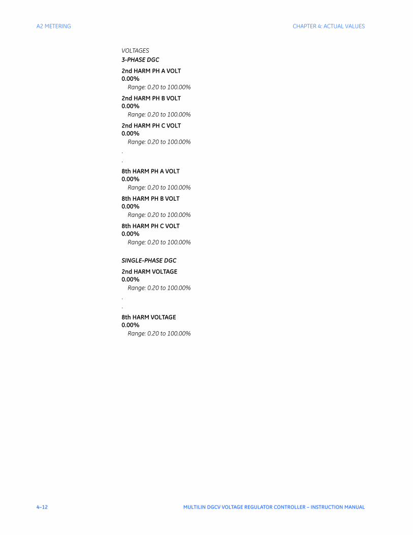
4–12 MULTILIN DGCV VOLTAGE REGULATOR CONTROLLER – INSTRUCTION MANUAL
A2 METERING CHAPTER 4: ACTUAL VALUES
VOLTAGES3-PHASE DGC
2nd HARM PH A VOLT0.00%
Range: 0.20 to 100.00%
2nd HARM PH B VOLT0.00%
Range: 0.20 to 100.00%
2nd HARM PH C VOLT0.00%
Range: 0.20 to 100.00%..
8th HARM PH A VOLT0.00%
Range: 0.20 to 100.00%
8th HARM PH B VOLT0.00%
Range: 0.20 to 100.00%
8th HARM PH C VOLT0.00%
Range: 0.20 to 100.00%
SINGLE-PHASE DGC
2nd HARM VOLTAGE0.00%
Range: 0.20 to 100.00%..
8th HARM VOLTAGE0.00%
Range: 0.20 to 100.00%

CHAPTER 4: ACTUAL VALUES A2 METERING
MULTILIN DGCV VOLTAGE REGULATOR CONTROLLER – INSTRUCTION MANUAL 4–13
Default screensThe measurements and metered values can also be viewed by scrolling Up or Down through the default screens as shown below:
Power calculationWhen Multilin DGCV is connected to all three-phase currents and voltages, the three-phase power is calculated as a sum of the three individual phase power quantities.When the Multilin DGCV is connected to only one current and one voltage input, the three phase power is calculated assuming balanced system, i.e. the computed single phase power is multiplied by 3. Refer to the following diagram showing the single phase and three-phase power computation for each combination of voltage and current input programmable under the Voltage and Current Sensing setup:

4–14 MULTILIN DGCV VOLTAGE REGULATOR CONTROLLER – INSTRUCTION MANUAL
A2 METERING CHAPTER 4: ACTUAL VALUES
Please note that for all equations below, the rotated phasor is the current phasor. The asterisk identifies conjugate value.0°) Three phase based on one phase calculation
-120°) Three phase based on one phase calculation
-240°) Three phase based on one phase calculation
-30°) Three phase based on one phase calculation
-90°) Three phase based on one phase calculation
-210°) Three phase based on one phase calculation
-150°) Three phase based on one phase calculation
-270°) Three phase based on one phase calculation
-330°) Three phase based on one phase calculation
Table 1: Power Computation for 3-phase Multilin DGCV
*) Three phase direct calculation
**) Aron method
ABC ACB
Current Transformer Connection
Current Transformer Connection
PhA PhB PhC PhA PhB PhC
Line-to-Ground Voltage
Va 0 -120 -240 0 -240 -120
Vb -240 0 -120 -120 0 -240
Vc -120 -240 0 -240 -120 0
Line-to-Line Voltage
Vab -30 -150 -270 -330 -210 -90
Vbc -270 -30 -150 -90 -330 -210
Vca -150 -270 -30 -210 -90 -330
ABC/ACB
CT Connection:
WYE
VT Connection
WYE *
DELTA **

CHAPTER 4: ACTUAL VALUES A3 RECORDS
MULTILIN DGCV VOLTAGE REGULATOR CONTROLLER – INSTRUCTION MANUAL 4–15
A3 Records
Figure 3: Records menu
Event recordsEvent Records include events generated by operation of the following functions:
• Control functions
• Raise and Lower tap commands
• Alarms, Blocks
• Change of inputs.
The events are stored in memory, which can store up to 256 events. Each event is stored with an event number, date, time, and analog data of interest. The following list shows the analog data viewable for each recorded event
CauseTimeDateLine CurrentLine Current AnglePhase A CurrentPhase B CurrentPhase C CurrentLine VoltageLine Voltage AngleVan (Wye,Va,Vb,Vc VT input)*Vbn (Wye,Va,Vb,Vc VT input)*Vcn (Wye,Va,Vb,Vc VT input)*Vab (Delta,Vab,Vbc,Vca VT input)*Vbc (Delta,Vab,Vbc,Vca VT input)*Vca (Delta,Vab,Vbc,Vca VT input)*Power Factor3Ph Real Power3Ph Reactive Power3Ph Apparent Power
ACTUAL VALUES
A1 STATUS
A2 METERING
A3 RECORDS
A4 TARGET MESSAGES
891970.cdr
A3 RECORDS
EVENT RECORDS
DATA LOGGER
CLEAR EVENT REC
CLEAR DATA LOGGER
▼
A3 DATA LOGGER
TOTAL TRIGGERS
TRIGGER CAUSE
DATA LOG STATUS
▼
A3 EVENT REC T421
E421,
“
Date
Event Record”
Time
...
A3 CLEAR DATA LOGGERCLEAR
A3 CLEAR EVENT RECCLEAR
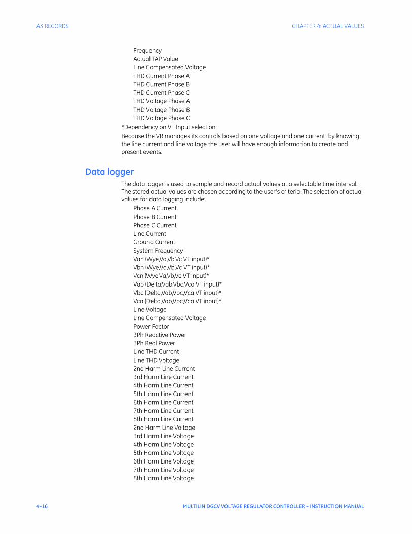
4–16 MULTILIN DGCV VOLTAGE REGULATOR CONTROLLER – INSTRUCTION MANUAL
A3 RECORDS CHAPTER 4: ACTUAL VALUES
FrequencyActual TAP ValueLine Compensated VoltageTHD Current Phase ATHD Current Phase BTHD Current Phase CTHD Voltage Phase ATHD Voltage Phase BTHD Voltage Phase C
*Dependency on VT Input selection.Because the VR manages its controls based on one voltage and one current, by knowing the line current and line voltage the user will have enough information to create and present events.
Data loggerThe data logger is used to sample and record actual values at a selectable time interval. The stored actual values are chosen according to the user’s criteria. The selection of actual values for data logging include:
Phase A CurrentPhase B CurrentPhase C CurrentLine CurrentGround CurrentSystem FrequencyVan (Wye,Va,Vb,Vc VT input)*Vbn (Wye,Va,Vb,Vc VT input)*Vcn (Wye,Va,Vb,Vc VT input)*Vab (Delta,Vab,Vbc,Vca VT input)*Vbc (Delta,Vab,Vbc,Vca VT input)*Vca (Delta,Vab,Vbc,Vca VT input)*Line VoltageLine Compensated VoltagePower Factor3Ph Reactive Power3Ph Real PowerLine THD CurrentLine THD Voltage2nd Harm Line Current3rd Harm Line Current4th Harm Line Current5th Harm Line Current6th Harm Line Current7th Harm Line Current8th Harm Line Current2nd Harm Line Voltage3rd Harm Line Voltage4th Harm Line Voltage5th Harm Line Voltage6th Harm Line Voltage7th Harm Line Voltage8th Harm Line Voltage
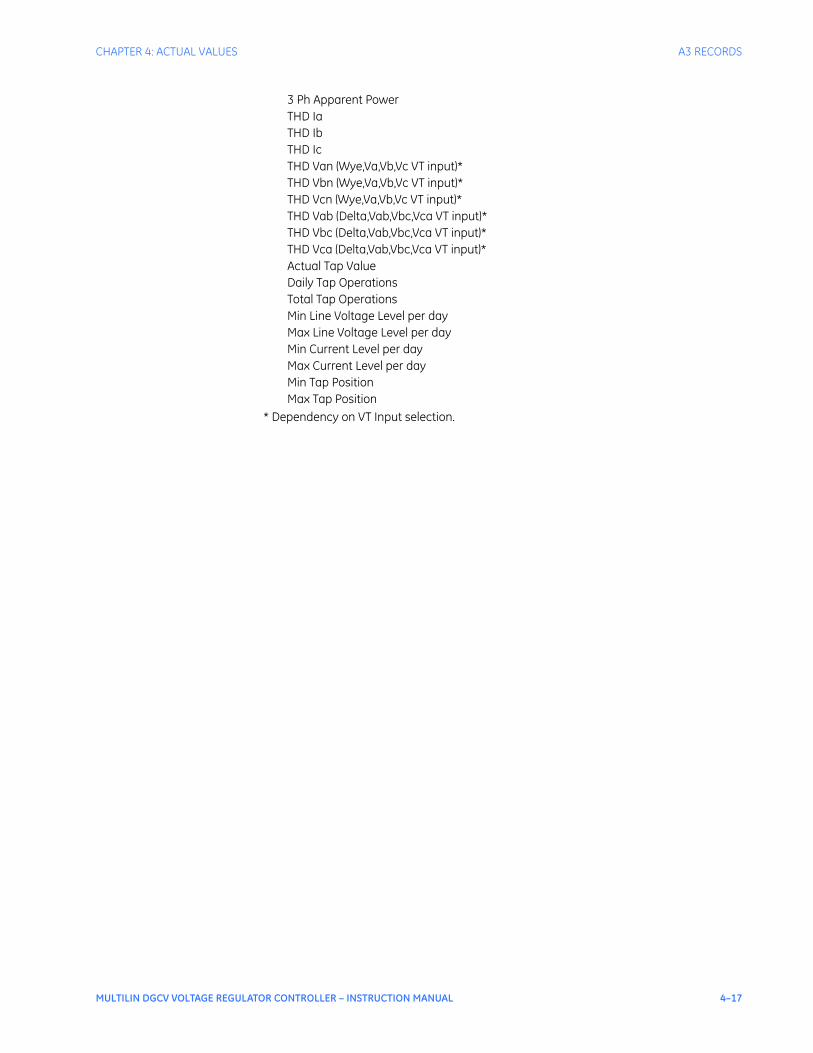
CHAPTER 4: ACTUAL VALUES A3 RECORDS
MULTILIN DGCV VOLTAGE REGULATOR CONTROLLER – INSTRUCTION MANUAL 4–17
3 Ph Apparent PowerTHD IaTHD IbTHD IcTHD Van (Wye,Va,Vb,Vc VT input)*THD Vbn (Wye,Va,Vb,Vc VT input)*THD Vcn (Wye,Va,Vb,Vc VT input)*THD Vab (Delta,Vab,Vbc,Vca VT input)*THD Vbc (Delta,Vab,Vbc,Vca VT input)*THD Vca (Delta,Vab,Vbc,Vca VT input)*Actual Tap ValueDaily Tap OperationsTotal Tap OperationsMin Line Voltage Level per dayMax Line Voltage Level per dayMin Current Level per dayMax Current Level per dayMin Tap PositionMax Tap Position
* Dependency on VT Input selection.

4–18 MULTILIN DGCV VOLTAGE REGULATOR CONTROLLER – INSTRUCTION MANUAL
A4 TARGET MESSAGES CHAPTER 4: ACTUAL VALUES
A4 Target messages
Multilin DGCV configuration errorsProper Multilin DGCV operation depends on properly selected settings. The Multilin DGCV checks the following settings for setting overlapping, and incompatibility:
• Voltage Level
• Bandwidth
• Voltage Reduction
• High Voltage Runback Limit
• Low Voltage Runback Limit
• Overvoltage Level
• Undervoltage Level.
Incorrectly selected settings may lead to incorrect VR operation, and in return this may be harmful for the tap changer and the transformer. For this reason, the Multilin DGCV is set to perform the following setpoint checks, and issue appropriate error messages.Errors are stored as flags in the Multilin DGCV register, and this allows several errors to be logged at the same time.
NOTE
NOTE: One should keep in mind, that the Multilin DGCV will allow the saving of a selected incorrect voltage setting. However in such cases, the Multilin DGCV will produce a Unit Configuration Error, and will inhibit Multilin DGCV auto operations.
If any of the above conditions do not match, an appropriate target message is shown in the display and a block is applied.
Displayed Error Message
Value Error Description Triggered upon saving an incorrect setting
No Error 0x0000 N.A.
Hi RB < Hi DB 0x0001 High Runback Limit below High Dead-Band
- High Runback Limit - Voltage Bandwidth
Lo RB < Lo DB 0x0002 Low Runback Limit above Low Dead-Band
- Low Runback Limit - Voltage Bandwidth
OV < UV 0x0004 Over-Voltage level below Under-Voltage level
- Over-Voltage Level - Under-Voltage Level
OV < Volt Level 0x0008 Over-Voltage below Voltage level - Over-Voltage Level - Voltage Level
UV > Volt Level 0x0010 Under-Voltage above Voltage level - Under-Voltage Level - Voltage Level
VRed1 < LoRB 0x0020 Voltage Reduction 1 below Low Runback Limit
- Voltage Reduction 1 - Low Runback Level
VRed1 < UV 0x0040 Voltage Reduction 1 below Under-Voltage level
- Voltage Reduction 1 - Under-Voltage Level
VRed2 < LoRB 0x0080 Voltage Reduction 2 below Low Runback Limit
- Voltage Reduction 2 - Low Runback Level
VRed2 < UV 0x0100 Voltage Reduction 2 below Under-Voltage level
- Voltage Reduction 2 - Under-Voltage Level
VRed3 < LoRB 0x0200 Voltage Reduction 3 below Low Runback Limit
- Voltage Reduction 3 - Low Runback Level
VRed3 < UV 0x0400 Voltage Reduction 3 below Under-Voltage level
- Voltage Reduction 3 - Under-Voltage Level

CHAPTER 4: ACTUAL VALUES A4 TARGET MESSAGES
MULTILIN DGCV VOLTAGE REGULATOR CONTROLLER – INSTRUCTION MANUAL 4–19
If the Setting Error was produced when in “Disabled” mode (control PB Disable/Enable set the VR to “Disabled”), no block is applied, and the “Alarm” LED turns on. The VR operation block will be applied when VR control is Enabled:
• When in Auto/Remote mode, the block is applied to all auto functions. The VR display will show the error message, and the "Alarm” LEDs will turn on.
• When in Manual mode, the block affects only the Over-Voltage and the Under-Voltage settings. The VR displays the error message, and turns on the “Alarm” LED.
Error messages can be reset only upon correcting the settings causing the errors Error Message example:The VR displays an Error Message in the following format until the error is corrected:

4–20 MULTILIN DGCV VOLTAGE REGULATOR CONTROLLER – INSTRUCTION MANUAL
A4 TARGET MESSAGES CHAPTER 4: ACTUAL VALUES
MULTILIN DGCV VOLTAGE REGULATOR CONTROLLER – INSTRUCTION MANUAL 5–1
Multilin DGCV Voltage Regulator Controller
Chapter 5: Settings
Digital Energy
Settings
S1 Product setup
The main Product Setup menu is shown below:

5–2 MULTILIN DGCV VOLTAGE REGULATOR CONTROLLER – INSTRUCTION MANUAL
S1 PRODUCT SETUP CHAPTER 5: SETTINGS
Figure 1: Product setup menu
S1 PASSWORD SECURITY
LOC SETPOINTS PSWD
LOC CONTROLS PSWD
S1 CLOCK SETUP
DATE (MM/DD/YYYY)
TIME (HH:MM:SS)
DLS ENABLE
DLS START MONTH
DLS START WEEK
DLS END MONTH
DLS END WEEK
DLS START WEEKDAY
DLS END WEEKDAY
▼
S1 PRODUCT SETUP
CLOCK SETUP
PASSWORD SECURITY
COMMUNICATIONS
EVENT RECORDER
DATA LOGGER
FRONT PANEL
INSTALLATION
▼
891964.cdr
S1 COMMUNICATIONS
RS485
MODBUS
DNP
S1 EVENT RECORDER
PICKUP EVENTS
TRIP EVENTS
ALARM EVENTS
CONTROL EVENTS
DROPOUT EVENTS
CONTACT INPUTS
VIRTUAL INPUTS
VIRTUAL OUTPUTS
SETTING DATE/TIME
▼
S1 FRONT PANEL
MESSAGE TIMEOUT
SCREEN SAVER
FLASH MESSAGE TIME
▼
S1 INSTALLATION
PRODUCT NAME
PRODUCT STATUS
▼
S1 DATA LOGGER
CONTINUOUS MODE
TRIGGER POSITION
SAMPLE RATE
DATA LOG TRGR SRC
CHANNEL 1
...
CHANNEL 10
▼
S1 RS485
RS485 BAUD RATE
PARITY
REAR RS485 PORT
COMM FAIL ALARM
▼
S1 MODBUS
MODBUS SLAVE ADR
S1 DNP
DNP GENERAL
DEFAULT VARIATION
DNP POINTS LIST
S1 DNP GENERAL
DNP ADDRESS
TIME SYNC IN PER
DNP MSG FRAG SIZE
▼
S1 DNP POINTS LIST
BINARY INPUTS
BINARY OUTPUTS
ANALOG INPUTS
S1 DEFAULT VARIATION
DNP OBJECT 1
DNP OBJECT 2
DNP OBJECT 20
DNP OBJECT 21
DNP OBJECT 22
DNP OBJECT 23
DNP OBJECT 30
DNP OBJECT 32
▼
S1 BINARY INPUTS
POINT 0
...
POINT 63
▼
S1 BINARY OUTPUTS
POINT 0 ON
POINT 0 OFF
...
POINT 15 ON
POINT 15 OFF
▼
S1 BINARY OUTPUTS
POINT 0 ENTRY
POINT 0 SCALE FCTR
POINT 0 DEADBAND
...
POINT 31 ENTRY
POINT 31 SCALE FCTR
POINT 31 DEADBAND
▼

CHAPTER 5: SETTINGS S1 PRODUCT SETUP
MULTILIN DGCV VOLTAGE REGULATOR CONTROLLER – INSTRUCTION MANUAL 5–3
ClockThe Multilin DGCV has an internal real time clock that performs time stamping for various features such as the event and transient recorders. Time synchronization priority uses Modbus or DNP commands as follows:Synchronization commands are all eventually translated into a MODBUS function, and as such are blocked from the MODBUS layer as required.There is no prioritization amongst synchronization commands. A synchronization command issued from DNP for example, can be directly followed by another from MODBUS, for example.PATH: SETPOINTS > S1 PRODUCT SETUP > CLOCK
DATE: (MM/DD/YYYY)
Range: Month: Jan, Feb, Mar, Apr, May, Jun, Jul, Aug, Sep, Oct, Nov, Dec Day: 1 to 31 Year: 2009 to 2099Default: Jan 15 2009
This setting sets the date in the specified format.
TIME: (HH:MM:SS)
Range: 0 to 23: 0 to 59: 0 to59Default: 03:15:50
This setting sets the time in the specified format.
DLS ENABLE
Range: Disabled, EnabledDefault: Disabled
With DLS Enabled, the main CPU has to maintain the information regarding AV.m_DaylightSavingsActive, because it is necessary in the comms CPU to translate from localtime to UTC in 61850 protocol. In addition, if SNTP is enabled, the main CPU will receive UTC time from comms CPU and it needs to apply this in order to pass it to localtime.
Without any other synchronization, DLS correction is applied only at 0200 hours on daylight saving months.
PATH: SETPOINTS > S1 PRODUCT SETUP > CLOCK > DLS ENABLE [ENABLED]
DLS START MONTH:
Range: Not Set, January, February, March, April, May, June, July, August, September, October, November, DecemberDefault: Not Set
This setting sets the month for the DLS start time.
DLS START WEEK:
Range: Not Set, 1st, 2nd, 3rd, 4th, LastDefault: Not Set
This setting sets the week of the month for the DLS start time.
DLS START WEEKDAY:
Range: Not Set, Mon, Tue, Wed, Thu, Fri, Sat, SunDefault: Not Set
This setting sets the weekday for the DLS start time.
DLS END MONTH:
Range: Not Set, January, February, March, April, May, June, July, August, September, October, November, DecemberDefault: Not Set
This setting sets the month for the end of the DLS time.
5–4 MULTILIN DGCV VOLTAGE REGULATOR CONTROLLER – INSTRUCTION MANUAL
S1 PRODUCT SETUP CHAPTER 5: SETTINGS
DLS END WEEK:
Range: Not Set, 1st, 2nd, 3rd, 4th, LastDefault: Not Set
This setting sets the week of the month for the end of the DLS time.
DLS END WEEKDAY:
Range: Not Set, Mon, Tue, Wed, Thu, Fri, Sat, SunDefault: Not Set
This setting sets the weekday for the end of the DLS time.
Password securityPassword security features are designed into the relay to provide protection against unauthorized setpoint changes and control. The relay has programmable passwords for both Local and Remote access, which can be used to allow setpoint changes and command execution from both the front panel and the communications ports. These passwords consist of 3 to 10 alphanumeric characters. The Local and the Remote passwords are initially set after entering in a Master Reset Password (MRP). The Master Reset Password (MRP) is set to “NULL” when the relay is shipped from the factory. When the MRP is programmed to “NULL” all password security is disabled.. The remote user may choose to allow the local user to change the local passwords.Each interface (RS485, USB, and front panel keypad) is independent of one another, meaning that enabling setpoint access on one interface does not enable access for any of the other interfaces (i.e., the password must be explicitly entered via the interface from which access is desired).The EnerVista DGCV Setup software incorporates a facility for programming the relay’s passwords as well as enabling/disabling setpoint access. For example, when an attempt is made to modify a setpoint but access is restricted, the program will prompt the user to enter the password and send it to the relay before the setpoint can actually be written to the relay. If a SCADA system is used for relay programming, it is up to the programmer to incorporate appropriate security for the application.Aside from being logged out of security, which allows the user to read setpoints and actual values only, three levels of security access are provided: Setpoint Level, Control Level, and Master Level. The Setpoint and Control Levels can be attained either locally using the Local passwords (USB port and keypad), or remotely using the Remote passwords (RS485 port). The user can have either Setpoint or Control Level active, but not both simultaneously from the same interface. The Master Level is used for setting and resetting of passwords, and includes all Setpoint and Control Level access rights. The Master Level cannot be attained from the keypad. The Master Reset Password must be 8 to 10 characters in length, and must contain at least 2 letters and 2 numbers. The Master Level can define whether the local user is permitted to change Local Passwords without having to enter the Master Level. The Master Reset Password is encrypted, and is not viewable from the keypad. If the Master Reset Password is lost, the user should contact the factory to decrypt the Master Reset Password.After password entry, the access level is maintained until a period of 5 minutes of inactivity has elapsed, after which the password must be re-entered. A power-loss or entering in the wrong password will log the user out of security.Further definition of the access levels is described as follows:SETPOINT LEVEL
• Changing settings under QUICK SETUP menu
• Changing settings under the SETPOINTS menu except the features requiring control access listed below

CHAPTER 5: SETTINGS S1 PRODUCT SETUP
MULTILIN DGCV VOLTAGE REGULATOR CONTROLLER – INSTRUCTION MANUAL 5–5
• Changing any setting under MAINTENANCE such as trip and close coil monitoring and breaker maintenance settings, except the features requiring control access listed below
• Changing the Local or Remote Setpoint Password, depending on the interface being accessed
CONTROL LEVEL
• Reset command
• Open and Close Breaker commands
• Virtual Input commands
• Clearing of event records, transient records, and other data
• Uploading new firmware
• Changing the Local or Remote Control Password, depending on the interface being accessed
MASTER LEVEL
• Setting and changing of all passwords including the Master Reset Password
• Disabling password security
• All Setpoint and Control Level access rights
For details on Password Security setup and handling using the EnerVista Setup software, refer to Chapter 3.
CommunicationsFigure 2: Main Communications menu
RS485 interface The Multilin DGCV is equipped with one serial RS485 communication port. The RS485 port has settings for baud rate and parity. It is important that these parameters agree with the settings used on the computer or other equipment that is connected to these ports. This port may be connected to a computer running the EnerVista DGCV Setup software. This software can download and upload setting files, view measured parameters, and upgrade the device firmware. A maximum of 32 -series devices can be daisy-chained and connected to a DCS, PLC, or PC using the RS485 port.Select the Settings > Communications > Serial Ports menu item in the program, or the SETPOINTS > S1 PRODUCT SETUP > COMMUNICATIONS > RS485 path on the display, to configure the serial port.
S1 RS485
RS485 BAUD RATE
PARITY
REAR 485 PORT
COMM FAIL ALARM
▼
S1 COMMUNICATIONS
RS485
MODBUS
DNP
891746.cdr
S1 MODBUS PROTOCOL
MODBUS SLAVE ADR
S1 DNP
DNP GENERAL
DEFAULT VARIATION
DNP POINTS LIST
▼

5–6 MULTILIN DGCV VOLTAGE REGULATOR CONTROLLER – INSTRUCTION MANUAL
S1 PRODUCT SETUP CHAPTER 5: SETTINGS
Figure 3: Serial port configuration settings
The following settings are available to configure the RS485 port.
BAUD RATE
Range: 9600, 19200, 38400, 57600, 115200Default: 115200
This setting specifies the baud rate (bits per second) for the RS485 port.
PARITY
Range: None, Odd, EvenDefault: None
This setting specifies the parity for the RS485 port.
Modbus The Modicon Modbus protocol is supported by the Multilin DGCV . Modbus is available via the RS485 serial link (Modbus RTU). The always acts as a slave device, meaning that it never initiates communications; it only listens and responds to requests issued by a master device. A subset of the Modbus protocol format is supported that allows extensive monitoring, programming, and control functions using read and write register commands. Refer to the Multilin DGCV Communications Guide for additional details on the Modbus protocol and the Modbus memory map.The Modbus server can simultaneously support two clients over serial RS485. The server is capable of reporting any indication or measurement and operating any output present in the device. A user-configurable input and output map is also implemented.The operates as a Modbus slave device onlySelect the Settings > Communications > Modbus > Protocol menu item in software, or the SETPOINTS > S1 PRODUCT SETUP > COMMUNICATIONS > MODBUS PROTOCOL path to set up the modbus protocol as shown below.
Figure 4: Modbus protocol configuration settings
The following Modbus settings are available:
MODBUS SLAVE ADDRESS
Range: 1 to 254 in steps of 1Default: 254
This setting specifies the Modbus slave address . Each device must have a unique address from 1 to 254. Address 0 is the broadcast address to which all Modbus slave devices listen. Addresses do not have to be sequential, but no two devices can have the same address or conflicts resulting in errors will occur. Generally, each device added to the link should use the next higher address starting at 1.
Please refer to the Multilin DGCV Communications Guide for details on how to set up the Modbus communications protocol.

CHAPTER 5: SETTINGS S1 PRODUCT SETUP
MULTILIN DGCV VOLTAGE REGULATOR CONTROLLER – INSTRUCTION MANUAL 5–7
DNP communication The menu structure for the DNP protocol is shown below.PATH: SETPOINTS > PRODUCT SETUP > COMMUNICATIONS > DNP
Figure 5: DNP communication settings menu
The following table, from the Multilin DGCV Communications Guide, shows the list of DNP Binary Inputs.
S1 DNP GENERAL
DNP ADDRESS
DNP TCP/UDP PORT
TME SYNC IIN PER.
DNP MSG FRAG SIZE
▼
S1 DNP
DNP GENERAL
DEFAULT VARIATION
DNP POINTS LIST
891743.cdr
POINT 0
...
POINT 1
POINT 2
POINT 63
▼
S1 DNP POINTS LIST
BINARY INPUTS
BINARY OUTPUT
ANALOG INPUTS
POINT 0 ENTRY
...
POINT 0 SCALE FCTR
POINT 0 DEADBAND
POINT 31 ENTRY
POINT 31 SCALE FCTR
POINT 31 DEADBAND
▼
POINT 0 ON
...
POINT 0 OFF
POINT 1 ON
POINT 1 OFF
POINT 15 ON
POINT 15 OFF
▼
DEFAULT VARIATION
DNP OBJECT 1
DNP OBJECT 2
DNP OBJECT 20
DNP OBJECT 21
DNP OBJECT 22
DNP OBJECT 23
DNP OBJECT 30
DNP OBJECT 32
Code Type Definition
FC134B unsigned 16 bits DNP Binary Inputs
0 Off
0x0040 Contact IN 1 On
0x0041 Contact IN 2 On
0x0042 Contact IN 3 On
0x0043 Contact IN 4 On
0x0044 Contact IN 5 On
0x0045 Contact IN 6 On
0x0046 Contact IN 7 On
0x0047 Contact IN 8 On
0x0048 Contact IN 9 On
0x0049 Contact IN 10 On
0x004A Contact IN 11 On
0x004B Contact IN 12 On
0x004C Contact IN 13 On
0x004D Contact IN 14 On
0x004E Contact IN 15 On

5–8 MULTILIN DGCV VOLTAGE REGULATOR CONTROLLER – INSTRUCTION MANUAL
S1 PRODUCT SETUP CHAPTER 5: SETTINGS
0x004F Contact IN 16 On
0x0050 Contact IN 17 On
0x0051 Contact IN 18 On
0x0060 Contact IN 1 Off
0x0061 Contact IN 2 Off
0x0062 Contact IN 3 Off
0x0063 Contact IN 4 Off
0x0064 Contact IN 5 Off
0x0065 Contact IN 6 Off
0x0066 Contact IN 7 Off
0x0067 Contact IN 8 Off
0x0068 Contact IN 9 Off
0x0069 Contact IN 10 Off
0x006A Contact IN 11 Off
0x006B Contact IN 12 Off
0x006C Contact IN 13 Off
0x006D Contact IN 14 Off
0x006E Contact IN 15 Off
0x006F Contact IN 16 Off
0x0070 Contact IN 17 Off
0x0071 Contact IN 18 Off
0x0080 Virtual IN 1 On
0x0081 Virtual IN 2 On
0x0082 Virtual IN 3 On
0x0083 Virtual IN 4 On
0x0084 Virtual IN 5 On
0x0085 Virtual IN 6 On
0x0086 Virtual IN 7 On
0x0087 Virtual IN 8 On
0x0088 Virtual IN 9 On
0x0089 Virtual IN 10 On
0x008A Virtual IN 11 On
0x008B Virtual IN 12 On
0x008C Virtual IN 13 On
0x008D Virtual IN 14 On
0x008E Virtual IN 15 On
0x008F Virtual IN 16 On
0x0090 Virtual IN 17 On
0x0091 Virtual IN 18 On
0x0092 Virtual IN 19 On
0x0093 Virtual IN 20 On
0x0094 Virtual IN 21 On
0x0095 Virtual IN 22 On
0x0096 Virtual IN 23 On
0x0097 Virtual IN 24 On
0x0098 Virtual IN 25 On
0x0099 Virtual IN 26 On
Code Type Definition
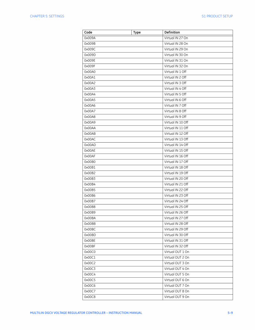
CHAPTER 5: SETTINGS S1 PRODUCT SETUP
MULTILIN DGCV VOLTAGE REGULATOR CONTROLLER – INSTRUCTION MANUAL 5–9
0x009A Virtual IN 27 On
0x009B Virtual IN 28 On
0x009C Virtual IN 29 On
0x009D Virtual IN 30 On
0x009E Virtual IN 31 On
0x009F Virtual IN 32 On
0x00A0 Virtual IN 1 Off
0x00A1 Virtual IN 2 Off
0x00A2 Virtual IN 3 Off
0x00A3 Virtual IN 4 Off
0x00A4 Virtual IN 5 Off
0x00A5 Virtual IN 6 Off
0x00A6 Virtual IN 7 Off
0x00A7 Virtual IN 8 Off
0x00A8 Virtual IN 9 Off
0x00A9 Virtual IN 10 Off
0x00AA Virtual IN 11 Off
0x00AB Virtual IN 12 Off
0x00AC Virtual IN 13 Off
0x00AD Virtual IN 14 Off
0x00AE Virtual IN 15 Off
0x00AF Virtual IN 16 Off
0x00B0 Virtual IN 17 Off
0x00B1 Virtual IN 18 Off
0x00B2 Virtual IN 19 Off
0x00B3 Virtual IN 20 Off
0x00B4 Virtual IN 21 Off
0x00B5 Virtual IN 22 Off
0x00B6 Virtual IN 23 Off
0x00B7 Virtual IN 24 Off
0x00B8 Virtual IN 25 Off
0x00B9 Virtual IN 26 Off
0x00BA Virtual IN 27 Off
0x00BB Virtual IN 28 Off
0x00BC Virtual IN 29 Off
0x00BD Virtual IN 30 Off
0x00BE Virtual IN 31 Off
0x00BF Virtual IN 32 Off
0x00C0 Virtual OUT 1 On
0x00C1 Virtual OUT 2 On
0x00C2 Virtual OUT 3 On
0x00C3 Virtual OUT 4 On
0x00C4 Virtual OUT 5 On
0x00C5 Virtual OUT 6 On
0x00C6 Virtual OUT 7 On
0x00C7 Virtual OUT 8 On
0x00C8 Virtual OUT 9 On
Code Type Definition
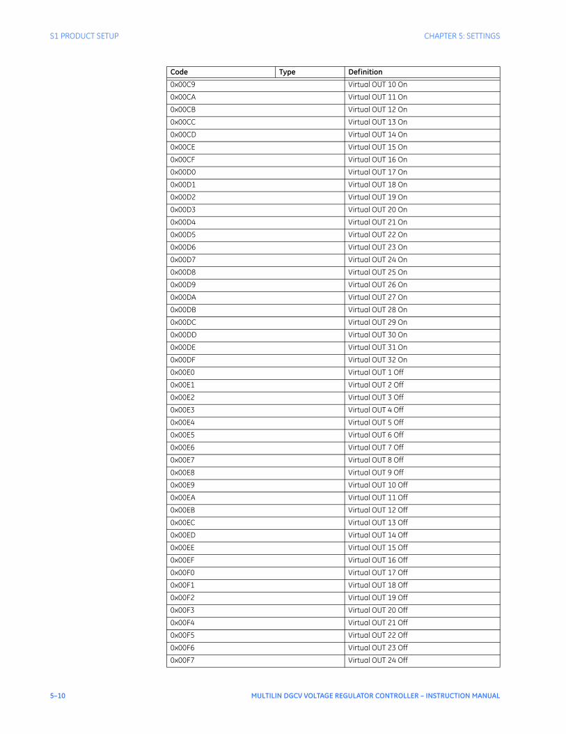
5–10 MULTILIN DGCV VOLTAGE REGULATOR CONTROLLER – INSTRUCTION MANUAL
S1 PRODUCT SETUP CHAPTER 5: SETTINGS
0x00C9 Virtual OUT 10 On
0x00CA Virtual OUT 11 On
0x00CB Virtual OUT 12 On
0x00CC Virtual OUT 13 On
0x00CD Virtual OUT 14 On
0x00CE Virtual OUT 15 On
0x00CF Virtual OUT 16 On
0x00D0 Virtual OUT 17 On
0x00D1 Virtual OUT 18 On
0x00D2 Virtual OUT 19 On
0x00D3 Virtual OUT 20 On
0x00D4 Virtual OUT 21 On
0x00D5 Virtual OUT 22 On
0x00D6 Virtual OUT 23 On
0x00D7 Virtual OUT 24 On
0x00D8 Virtual OUT 25 On
0x00D9 Virtual OUT 26 On
0x00DA Virtual OUT 27 On
0x00DB Virtual OUT 28 On
0x00DC Virtual OUT 29 On
0x00DD Virtual OUT 30 On
0x00DE Virtual OUT 31 On
0x00DF Virtual OUT 32 On
0x00E0 Virtual OUT 1 Off
0x00E1 Virtual OUT 2 Off
0x00E2 Virtual OUT 3 Off
0x00E3 Virtual OUT 4 Off
0x00E4 Virtual OUT 5 Off
0x00E5 Virtual OUT 6 Off
0x00E6 Virtual OUT 7 Off
0x00E7 Virtual OUT 8 Off
0x00E8 Virtual OUT 9 Off
0x00E9 Virtual OUT 10 Off
0x00EA Virtual OUT 11 Off
0x00EB Virtual OUT 12 Off
0x00EC Virtual OUT 13 Off
0x00ED Virtual OUT 14 Off
0x00EE Virtual OUT 15 Off
0x00EF Virtual OUT 16 Off
0x00F0 Virtual OUT 17 Off
0x00F1 Virtual OUT 18 Off
0x00F2 Virtual OUT 19 Off
0x00F3 Virtual OUT 20 Off
0x00F4 Virtual OUT 21 Off
0x00F5 Virtual OUT 22 Off
0x00F6 Virtual OUT 23 Off
0x00F7 Virtual OUT 24 Off
Code Type Definition
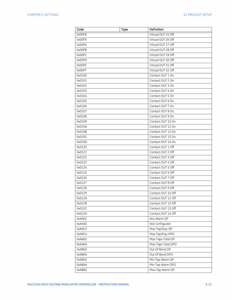
CHAPTER 5: SETTINGS S1 PRODUCT SETUP
MULTILIN DGCV VOLTAGE REGULATOR CONTROLLER – INSTRUCTION MANUAL 5–11
0x00F8 Virtual OUT 25 Off
0x00F9 Virtual OUT 26 Off
0x00FA Virtual OUT 27 Off
0x00FB Virtual OUT 28 Off
0x00FC Virtual OUT 29 Off
0x00FD Virtual OUT 30 Off
0x00FE Virtual OUT 31 Off
0x00FF Virtual OUT 32 Off
0x0100 Contact OUT 1 On
0x0101 Contact OUT 2 On
0x0102 Contact OUT 3 On
0x0103 Contact OUT 4 On
0x0104 Contact OUT 5 On
0x0105 Contact OUT 6 On
0x0106 Contact OUT 7 On
0x0107 Contact OUT 8 On
0x0108 Contact OUT 9 On
0x0109 Contact OUT 10 On
0x010A Contact OUT 11 On
0x010B Contact OUT 12 On
0x010C Contact OUT 13 On
0x010D Contact OUT 14 On
0x0120 Contact OUT 1 Off
0x0121 Contact OUT 2 Off
0x0122 Contact OUT 3 Off
0x0123 Contact OUT 4 Off
0x0124 Contact OUT 5 Off
0x0125 Contact OUT 6 Off
0x0126 Contact OUT 7 Off
0x0127 Contact OUT 8 Off
0x0128 Contact OUT 9 Off
0x0129 Contact OUT 10 Off
0x012A Contact OUT 11 Off
0x012B Contact OUT 12 Off
0x012C Contact OUT 13 Off
0x012D Contact OUT 14 Off
0xA002 Any Alarm OP
0xA482 Not Configured
0xA9C2 Max Tap/Day OP
0xA9C4 Max Tap/Day DPO
0xAA02 Max Taps Total OP
0xAA04 Max Taps Total DPO
0xAB02 Out Of Band OP
0xAB04 Out Of Band DPO
0xAB42 Min Tap Alarm OP
0xAB44 Min Tap Alarm DPO
0xAB82 Max Tap Alarm OP
Code Type Definition
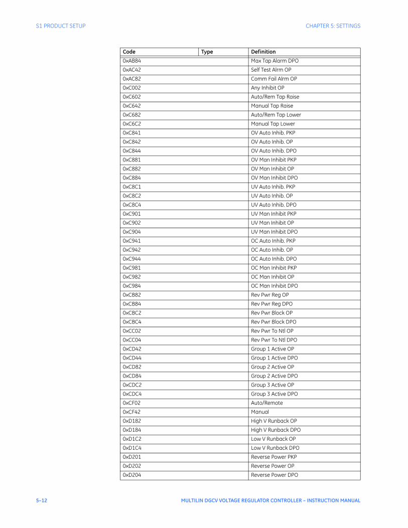
5–12 MULTILIN DGCV VOLTAGE REGULATOR CONTROLLER – INSTRUCTION MANUAL
S1 PRODUCT SETUP CHAPTER 5: SETTINGS
0xAB84 Max Tap Alarm DPO
0xAC42 Self Test Alrm OP
0xAC82 Comm Fail Alrm OP
0xC002 Any Inhibit OP
0xC602 Auto/Rem Tap Raise
0xC642 Manual Tap Raise
0xC682 Auto/Rem Tap Lower
0xC6C2 Manual Tap Lower
0xC841 OV Auto Inhib. PKP
0xC842 OV Auto Inhib. OP
0xC844 OV Auto Inhib. DPO
0xC881 OV Man Inhibit PKP
0xC882 OV Man Inhibit OP
0xC884 OV Man Inhibit DPO
0xC8C1 UV Auto Inhib. PKP
0xC8C2 UV Auto Inhib. OP
0xC8C4 UV Auto Inhib. DPO
0xC901 UV Man Inhibit PKP
0xC902 UV Man Inhibit OP
0xC904 UV Man Inhibit DPO
0xC941 OC Auto Inhib. PKP
0xC942 OC Auto Inhib. OP
0xC944 OC Auto Inhib. DPO
0xC981 OC Man Inhibit PKP
0xC982 OC Man Inhibit OP
0xC984 OC Man Inhibit DPO
0xCB82 Rev Pwr Reg OP
0xCB84 Rev Pwr Reg DPO
0xCBC2 Rev Pwr Block OP
0xCBC4 Rev Pwr Block DPO
0xCC02 Rev Pwr To Ntl OP
0xCC04 Rev Pwr To Ntl DPO
0xCD42 Group 1 Active OP
0xCD44 Group 1 Active DPO
0xCD82 Group 2 Active OP
0xCD84 Group 2 Active DPO
0xCDC2 Group 3 Active OP
0xCDC4 Group 3 Active DPO
0xCF02 Auto/Remote
0xCF42 Manual
0xD182 High V Runback OP
0xD184 High V Runback DPO
0xD1C2 Low V Runback OP
0xD1C4 Low V Runback DPO
0xD201 Reverse Power PKP
0xD202 Reverse Power OP
0xD204 Reverse Power DPO
Code Type Definition

CHAPTER 5: SETTINGS S1 PRODUCT SETUP
MULTILIN DGCV VOLTAGE REGULATOR CONTROLLER – INSTRUCTION MANUAL 5–13
Event recorderThe Event Recorder runs continuously, capturing and storing the last 256 events. All events are stored in a non-volatile memory where the information is maintained for up to 3 days in case of lost Multilin DGCV control power. PATH: SETPOINTS > S1 PRODUCT SETUP > EVENT RECORDER
PICKUP EVENTS
Range: Disabled, EnabledDefault: Disabled
When set to “Enabled”, the event recorder records the events that occur when a protection element picks up.
DROPOUT EVENTS
Range: Disabled, EnabledDefault: Disabled
When set to “Enabled” the event recorder records the dropout state of a protection element.
ALARM EVENTS
Range: Disabled, EnabledDefault: Enabled
These events include the elements programmed as an “ALARM” or “LATCHED ALARM” function, which detect power system conditions considered as an alarm.
CONTROL EVENTS
Range: Disabled, EnabledDefault: Enabled
If set to “Enabled”, the event recorder records events caused by the performance of the programmed control elements.
CONTACT INPUTS
Range: Disabled, EnabledDefault: Enabled
When set to “Enabled”, the event recorder will record the event when a contact input changes its state.
0xD242 Volt Reduct. 1 OP
0xD244 Volt Reduct. 1 DPO
0xD282 Volt Reduct. 2 OP
0xD284 Volt Reduct. 2 DPO
0xD2C2 Volt Reduct. 3 OP
0xD2C4 Volt Reduct. 3 DPO
0xD4C2 Unsuc Tap Chge OP
0xD4C4 Unsuc Tap Chge DPO
0xD502 Incomp Tap Seq OP
0xD504 Incomp Tap Seq DPO
0xE882 Grp Change Blk OP
0xE884 Grp Change Blk DPO
0xEE02 Tap Chg Inhib OP
0xEE04 Tap Chg Inhib DPO
Code Type Definition

5–14 MULTILIN DGCV VOLTAGE REGULATOR CONTROLLER – INSTRUCTION MANUAL
S1 PRODUCT SETUP CHAPTER 5: SETTINGS
VIRTUAL INPUTS
Range: Disabled, EnabledDefault: Enabled
When set to “Enabled”, the event recorder records the events which occur upon state changes of any virtual input.
VIRTUAL OUTPUTS
Range: Disabled, EnabledDefault: Enabled
When set to “Enabled”, the event recorder records the events which occur upon state changes of any virtual output.
SETTING DATE/TIME
Range: Disabled, EnabledDefault: Disabled
When set to “Enabled” the Event Recorder records the events which occur upon Date and/or Time settings made by the user.
DataloggerThe following setpoints are available:
SAMPLE RATE
Range: 1 min, 5 min, 10 min, 15 min, 30 min, 60 min, DisableDefault: 1 min
Determines how often data is stored in the data log.
CONTINUOUS MODE
Range: Disabled, EnabledDefault: Disabled
Determines whether or not the trigger data is overwritten with new data. Enabled will overwrite the previous trigger data with new trigger data. When Disabled, the data log will run until filled with 256 samples. Continuous Mode should be used when the data is stored externally by a polling system. The sample rate should be chosen to match the poll rate of the external program.
TRIGGER POSITION
Range: 0 to 100% steps of 1%Default: 25%
Percentage of the sample buffer used for pretrigger samples.
DATA LOG TRIG SRC
Range: Command, VO1 to VO32, Any Trip Pickup, Any Trip, Any Trip Dropout, Any Alarm Pickup, Any Alarm, Any Alarm DropoutDefault: Command
Selects a trigger source. Command is always active. Logic Elements can be used to create combinations of trigger sources.
CHANNEL 1 SOURCE
Range: Disabled, Phase A Current, Phase B Current, Phase C Current, Average Phase Current, Motor Load, Current Unbalance, Ground Current, System Frequency, Vab, Vbc, Vca, Van, Vbn, Vcn, Power Factor, Real Power (kW), Reactive Power (kvar), Apparent Power

CHAPTER 5: SETTINGS S1 PRODUCT SETUP
MULTILIN DGCV VOLTAGE REGULATOR CONTROLLER – INSTRUCTION MANUAL 5–15
(kVA), Positive Watthours, Positive Varhours, Hottest Stator RTD, Thermal Capacity Used, RTD #1, RTD #2, RTD #3, RTD #4, RTD #5, RTD #6, RTD #7, RTD #8, RTD #9, RTD #10, RTD #11, RTD #12Default: Disabled
Selects the data to be stored for each sample of the data log channel.
NOTE
NOTE: Sources and Defaults for Channels 2 to 10 are the same as those for Channel 1.
Front panelThe user can send a message to the display, that will override any normal message by sending text through Modbus.PATH: SETPOINTS > S1 PRODUCT SETUP > FRONT PANEL
FLASH MESSAGE TIME
Range: 1 s to 65535 sDefault: 5 s
Flash messages are status, warning, error, or information messages displayed for several seconds in response to certain key presses during setting programming. These messages override any normal messages. The duration of a flash message on the display can be changed to accommodate different reading rates.
MESSAGE TIMEOUT
Range: 1 s to 65535 sDefault: 30 s
If the keypad is inactive for a period of time, the relay automatically reverts to a default message. The inactivity time is modified via this setting to ensure messages remain on the screen long enough during programming or reading of actual values.
SCREEN SAVER
Range: Off, 1 min to 10000 minDefault: Off
The life of the LCD backlight can be prolonged by enabling the Screen Saver mode.
If the keypad is inactive for the selected period of time, the Multilin DGCV automatically shuts off the LCD screen. Any activity (keypress, alarm, trip, or target message) will restore screen messages.
InstallationPATH: SETPOINTS > S1 PRODUCT SETUP > INSTALLATION
PRODUCT NAME
Range: Product Name, Alpha-numeric (18 characters)Default: DGC Name
The PRODUCT NAME setting allows the user to uniquely identify a Multilin DGCV unit. This name will appear on generated reports. This name is also used to identify specific devices which are engaged in automatically sending/receiving data over the communications channel.
PRODUCT STATUS
Range: Not Ready, ReadyDefault: Not Ready
Allows the user to activate/deactivate the Multilin DGCV . The Multilin DGCV is not operational when set to "Not Ready."

5–16 MULTILIN DGCV VOLTAGE REGULATOR CONTROLLER – INSTRUCTION MANUAL
S2 SYSTEM SETUP CHAPTER 5: SETTINGS
S2 System setup
The Voltage Regulator can be connected to any available pair of voltage and current inputs, or to three-phase currents and voltage inputs, all programmable through the Current and Voltage Sensing menus. During normal loading conditions the transformer three phase currents and voltages are balanced. The power computation from the VR connected to a single-phase current and single-phase voltage is calculated by extrapolating the single-phase power to three-phase power measurement.
Figure 6: System setup menu
The following AC inputs need to be configured:
S2 SYSTEM SETUP
CURRENT SENSING
VOLTAGE SENSING
POWER SYSTEM
TAP CHANGER
TAP SENSING
▼
891965.cdr
S2 TAP CHANGER
LTC NUMBER OF TAPS
LTC NEUTRAL TAP
LTC TIME DELAY
LTC INHIBIT INPUT
MAX TAPS / DAY
MAX TAPS TOTAL
▼
S2 CURRENT SENSING
CURRENT INPUT
PHASE CT PRIMARY
PHASE CT SECONDARY
GND CT PRIMARY
GND CT SECONDARY
▼
S2 VOLTAGE SENSING
VOLTAGE INPUT
VT RATIO
VT SECONDARY
VT CALIBRATION
▼
S2 POWER SYSTEM
SYSTEM ROTATION
NOMINAL FREQUENCY
▼
S2 TAP SENSING
BCD BIT 1 INPUT
...
BCD BIT 6 INPUT
▼

CHAPTER 5: SETTINGS S2 SYSTEM SETUP
MULTILIN DGCV VOLTAGE REGULATOR CONTROLLER – INSTRUCTION MANUAL 5–17
Current sensingPATH: SETPOINTS > S2 SYSTEM SETUP > S2 CURRENT SENSING
CT PRIMARY
Range: 1 A or 5 A: 1 to 6000 A in steps of 1 ARange: 0.2 A: 1 to 400 A in steps of 1 ADefault: 1 A
This setpoint defines the ratio of the rated primary and secondary currents of the connected current transformer. The range of CT primary setting depends on the current transformer specified at the time of Multilin DGCV ordering.
NOTE
NOTE: The maximum CT primary current for the Multilin DGCV ordered for current sensing of 0.2 A does not exceed 400 A.
Voltage sensingPATH: SETPOINTS > S2 SYSTEM SETUP > S2 VOLTAGE SENSING
VT INPUT - 0.2 A CT
Range: Line-to-Ground, Line-to-LineDefault: Line-to-Ground
For Multilin DGCV orders with 0.2 A CT, this setpoint provides a setting selection of either Line-To-Ground, or Line-To-Line.
VT INPUT - 1 A to 5 A CT
Range: Line-to-Ground, Line-to-Line, Wye, DeltaDefault: Wye
For Multilin DGCV orders with 1 A to 5 A CT, this setpoint provides a setting selection of Line-To-Ground, Line-To-Line, Wye, or Delta.
VT RATIO
Range: 1 to 600 in steps of 1Default: 1:1
This setting specifies the ratio between the primary and the secondary voltages of the connected Voltage Transformer.
VT SECONDARY
Range: 60 to 250 V in steps of 1 VDefault: 120 V
This setting specifies the nominal secondary voltage of the voltage transformer as connected to the controller.
VT CALIBRATION
Range: 0.950 to 1.050 in steps of 0.001Default: 1.000
This setpoint allows the user to calibrate the voltage channel and obtain better accuracy at the working voltage.
The calculated RMS voltage is multiplied by this factor. A maximum deviation of ±5% is allowed.
5–18 MULTILIN DGCV VOLTAGE REGULATOR CONTROLLER – INSTRUCTION MANUAL
S2 SYSTEM SETUP CHAPTER 5: SETTINGS
Power systemPATH: SETPOINTS > S2 SYSTEM SETUP > POWER SYSTEM
SYSTEM ROTATION
Range: ABC, ACBDefault: ABC
This setting defines the phase rotation of the (3-Phase) power system.
VT/CT PHASING
Range: 0° to -330° in steps of -30°Default: 0°
This setting specifies the angle by which the current lags the voltage.
Refer to A2 METERING \ POWER CALCULATION for power calculation based on VT/CT phasing and the type of Multilin DGCV ordered.
NOMINAL FREQUENCY
Range: 50 Hz, 60 HzDefault: 60 Hz
This setting defines the frequency of the power system.
Tap changerPATH: SETPOINTS > S2 SYSTEM SETUP > S2 TAP CHANGER
TAP MAX
Range: 0 to +39 in steps of 1Default: +16
This setting defines the maximum tap limit for the controlled tap changer. The Multilin DGCV uses this setting to signal when the maximum tap is reached, and to block any further RAISE TAP commands.
TAP MIN
Range: -19 to +35 in steps of 1Default: -16
This setting defines the minimum tap limit for the controlled tap changer. The Voltage Regulator uses this setting to signal when the minimum tap is reached, and to block further LOWER TAP change commands.
TIME DELAY
Range: 0.0 to 300.0 sec in steps of 0.1 secDefault: 1.0 sec
The Transformer Tap changer switches from one tap to another with some time delay. This setting defines the time that it takes to change from one tap position to the next.
INHIBIT INPUT
Range: Off, Contact Inputs 1 to x, Virtual Input 1 to 32, Virtual Output 1 to 32Default: Off
This setting indicates the input used to inhibit the operation of the tap changer upon energizing.
MAX TAPS/DAY
Range: Off, 1 to 100 in steps of 1Default: 10
This is the maximum number of tap operations per day before an alarm occurs.

CHAPTER 5: SETTINGS S2 SYSTEM SETUP
MULTILIN DGCV VOLTAGE REGULATOR CONTROLLER – INSTRUCTION MANUAL 5–19
MAX TAPS TOTAL
Range: Off, 1 to 10000 in steps of 1Default: 1000
This is the maximum number of tap operations in total before an alarm occurs.
MAX/MIN LIMITS
Range: Disabled, EnabledDefault: Enabled
This setting enables or disables the application of the programmed TAP MAX and TAP MIN to be used as limits for the tap changer.
Tap sensingPOSITION SWITCHPATH: SETPOINTS > S2 SYSTEM SETUP > S2 TAP SENSING
TAP TRACKING
Range: Position Switch, BCDDefault: Position Switch
This setpoint shows the type for tap position detection.
With “Position Switch” selected under the Tap Tracking setting, the physical position switch that resides within the tap position indicator should be wired to the analog input labeled as 5 and 6 from the first IO_C card. This method of tap position detection requires also, that the neutral tap switch residing in the tap changer mechanism be wired to the neutral tap digital input from the controller.
When a pulse from the wired tap position switch is detected, the controller updates the tap position by moving one tap up or one tap down, depending on the direction of the issued command.
The neutral contact is fully programmable as per the following setpoint:
NTRL TAP INPUT
Range: Off, Contact Inputs 1 to xDefault: Off
This setting configures the digital input to detect the neutral tap position. Some step voltage regulators indicate the neutral tap position by an external contact. When the position switch is chosen as tap tracking method this input is the only mechanism to detect the neutral tap.
The “Position Switch” tap tracking method is based on two actions; one is the command sent to either the “Raise Tap”, or “Lower Tap” contact output, and the other is the pulse feedback from the position switch, that reflects the change of the tap position. The issued command contributes to detection of tap position direction, where the detected pulse feedback from the tap position switch is used to confirm the change.
With the “Position switch” tap tracking’ method, the closing of the tap changer neutral switch is also used to re-calibrate/re-synchronize the controller’s tap position.
BCD
TAP TRACKING
Range: Position Switch, BCDDefault: BCD
This specifies the BCD (Binary Coded Decimal) setpoint used for tap position monitoring.

5–20 MULTILIN DGCV VOLTAGE REGULATOR CONTROLLER – INSTRUCTION MANUAL
S2 SYSTEM SETUP CHAPTER 5: SETTINGS
NEUTRAL TAP
Range: -17 to +37Default: 0
This setting defines the neutral tap position on the controller. The “Neutral Tap” reflects the tap changer neutral tap as detected by BCD. The Neutral Tap LED will turn on when the tap changer is at neutral tap.
NOTE
NOTE: For BCD selection, the neutral tap must be programmed in order to provide the location of the neutral tap position.
To configure the BCD decoder inputs into an IO_C card the BCD BIT x INPUT settings must be programmed. These six settings are located under SETPOINTS/SYSTEM SETUP/TAP SENSING option menu. With four BCD bits programmed, only 9 tap positions can be detected. Five BCD bits programmed can be used for detection of up to 19 tap positions. With all 6 BCD bits programmed, the VR can detect up to 39 tap positions.
The physical connection between the output BCD decoder and the IO_C card is shown below:
BCD BIT 1 to 5 INPUT
Range: Off, Contact Inputs 1 to x, Virtual Input 1 to 32, Virtual Output 1 to 32 Default: Off
The six BCD inputs require selection of contact inputs, virtual inputs, or virtual outputs. The tap position is detected by the state combination of high/low bits received from the tap changer mechanism.
BCD BIT 6 INPUT
Range: Off, Contact Inputs 1 to x, Virtual Input 1 to 32, Virtual Output 1 to 32 Default: Off
This input provides the configuration of the BCD Bit 6 input. The tap position provided by the transformer can be either positive from 1 to 39, or positive and negative from -19 to 19.
BCD BIT 6 input provides the configuration of the positive BCD BIT 6 or the sign (-) of the BCD code.
The selection of BCD BIT 6 working mode is made according to the TAP MIN setting.
When the TAP MIN setpoint is configured with a negative value, the BCD BIT 6 will provide the sign (-) of the BCD. Hence, the maximum range for BCD tap detection of negative and positive taps goes from -19 to +19.
When, TAP MIN setting is positive, the BCD BIT 6 INPUT provides the BCD 20 code. As a result, the full BCD range goes from 1 to 39.
The selection of a suitable setting depends on the user’s criteria. In both cases, when the BCD format is chosen, the neutral tap position must be entered.

CHAPTER 5: SETTINGS S2 SYSTEM SETUP
MULTILIN DGCV VOLTAGE REGULATOR CONTROLLER – INSTRUCTION MANUAL 5–21
Figure 7: Connection Diagram - BDC decoder to IO_C card (up to 19 taps)
BCD inputs are coded in the following way:
• +Tap – means a positive tap has been programmed under MIN TAP setting.
• -Tap – means a negative tap has been programmed under MIN TAP setting.
MIN TAP BCD bit 6 Input
BCD bit 5 Input
BCD bit 4 Input
BCD bit 3 Input
BCD bit 2 Input
BCD bit 1 Input
TAP Position
+Tap 0 0 0 0 0 0 0
+Tap 0 0 0 0 0 1 1
+Tap 0 0 0 0 1 0 2
+Tap 0 0 0 0 1 1 3
+Tap 0 0 0 1 0 0 4
+Tap 0 0 0 1 0 1 5
+Tap 0 0 0 1 1 0 6
+Tap 0 0 0 1 1 1 7
+Tap 0 0 1 0 0 0 8
+Tap 0 0 1 0 0 1 9
+Tap 0 0 1 0 1 0 invalid
+Tap 0 0 1 0 1 1 invalid
+Tap 0 0 1 1 0 0 invalid
+Tap 0 0 1 1 0 1 invalid
+Tap 0 0 1 1 1 0 invalid
+Tap 0 0 1 1 1 1 invalid

5–22 MULTILIN DGCV VOLTAGE REGULATOR CONTROLLER – INSTRUCTION MANUAL
S2 SYSTEM SETUP CHAPTER 5: SETTINGS
MIN TAP BCD bit 6 Input
BCD bit 5 Input
BCD bit 4 Input
BCD bit 3 Input
BCD bit 2 Input
BCD bit 1 Input
TAP Position
+Tap 0 1 0 0 0 0 10
+Tap 0 1 0 0 0 1 11
+Tap 0 1 0 0 1 0 12
+Tap 0 1 0 0 1 1 13
+Tap 0 1 0 1 0 0 14
+Tap 0 1 0 1 0 1 15
+Tap 0 1 0 1 1 0 16
+Tap 0 1 0 1 1 1 17
+Tap 0 1 1 0 0 0 18
+Tap 0 1 1 0 0 1 19
+Tap 0 1 1 0 1 0 invalid
+Tap 0 1 1 0 1 1 invalid
+Tap 0 1 1 1 0 0 invalid
+Tap 0 1 1 1 0 1 invalid
+Tap 0 1 1 1 1 0 invalid
+Tap 0 1 1 1 1 1 invalid
MIN TAP BCD bit 6 Input
BCD bit 5 Input
BCD bit 4 Input
BCD bit 3 Input
BCD bit 2 Input
BCD bit 1 Input
TAP Position
+Tap 1 0 0 0 0 0 20
+Tap 1 0 0 0 0 1 21
+Tap 1 0 0 0 1 0 22
+Tap 1 0 0 0 1 1 23
+Tap 1 0 0 1 0 0 24
+Tap 1 0 0 1 0 1 25
+Tap 1 0 0 1 1 0 26
+Tap 1 0 0 1 1 1 27
+Tap 1 0 1 0 0 0 28
+Tap 1 0 1 0 0 1 29
+Tap 1 0 1 0 1 0 invalid
+Tap 1 0 1 0 1 1 invalid
+Tap 1 0 1 1 0 0 invalid
+Tap 1 0 1 1 0 1 invalid
+Tap 1 0 1 1 1 0 invalid
+Tap 1 0 1 1 1 1 invalid

CHAPTER 5: SETTINGS S2 SYSTEM SETUP
MULTILIN DGCV VOLTAGE REGULATOR CONTROLLER – INSTRUCTION MANUAL 5–23
MIN TAP BCD bit 6 Input
BCD bit 5 Input
BCD bit 4 Input
BCD bit 3 Input
BCD bit 2 Input
BCD bit 1 Input
TAP Position
+Tap 1 1 0 0 0 0 30
+Tap 1 1 0 0 0 1 31
+Tap 1 1 0 0 1 0 32
+Tap 1 1 0 0 1 1 33
+Tap 1 1 0 1 0 0 34
+Tap 1 1 0 1 0 1 35
+Tap 1 1 0 1 1 0 36
+Tap 1 1 0 1 1 1 37
+Tap 1 1 1 0 0 0 38
+Tap 1 1 1 0 0 1 39
+Tap 1 1 1 0 1 0 invalid
+Tap 1 1 1 0 1 1 invalid
+Tap 1 1 1 1 0 0 invalid
+Tap 1 1 1 1 0 1 invalid
+Tap 1 1 1 1 1 0 invalid
+Tap 1 1 1 1 1 1 invalid
... ... ... ... ... ... ... ...
-Tap 0 0 0 0 0 1 -1
-Tap 0 0 0 0 0 0 0
-Tap 1 0 0 0 0 0 0
-Tap 1 0 0 0 0 1 -1
-Tap 1 0 0 0 1 0 -2
... ... ... ... ... ... ... ...
-Tap 1 1 1 0 0 1 -19

5–24 MULTILIN DGCV VOLTAGE REGULATOR CONTROLLER – INSTRUCTION MANUAL
S3 VOLTAGE REGULATOR CHAPTER 5: SETTINGS
S3 Voltage regulator
Figure 8: Voltage Regulator and Controls menu
VOLTAGE LEVEL (BANDCENTER)The Voltage Level defines the desired level of voltage to be held at the load side of the power transformer. In many cases this voltage level is set to a 120 V secondary value that corresponds to the desired primary voltage from the transformer load side. It is commonly required that the voltage at the load be held in the range of 114 V to 126 V, although the
S3 VOLT REGULATOR
SETPOINT GROUP 1
SETPOINT GROUP 2
SETPOINT GROUP 3
SETPOINTS
S1 PRODUCT SETUP
S2 SYSTEM SETUP
S3 VOLT REGULATOR
S4 CONTROLS
S5 INPUTS/OUTPUTS
▼
S3 SETPOINT GROUP 1,2,3
MAIN REGULATION
VOLT RUNBCK LIMITS
VOLTAGE REDUCTION
INHIBIT FUNCTIONS
POWER OVERRIDE
▼
S4 REMOTE CONTROL
REMOTE RAISE TAP
REMOTE LOWER TAP
▼
891957.cdr
S4 CHANGE SETP GROUP
SET GROUP 2 ACTIVE
BLK GROUP CHANGE
SET GROUP 3 ACTIVE
▼
S4 VIRTUAL INPUTS
VIRTUAL INPUT 1
...
VIRTUAL INPUT 2
VIRTUAL INPUT 32
▼
S4
RESET
REMOTE RST/DH RST
S3 MAIN REGULATION
VOLTAGE LEVEL
BANDWIDTH
REGULATION TYPE
COMPUTATION MODE
COMPUTATION DELAY
OPERATION MODE
LDC RESISTIVE R
LDC INDUCTIVE X
▼
S3 VOLTAGE RUNBCK LIMITS
HIGH V RUNBCK LIMT
LOW V RUNBCK LIMT
▼
S3 VOLTAGE REDUCTION
VOLT REDUCTION 1
VOLT REDUC 1 INPUT
VOLT REDUCTION 2
VOLT REDUC 2 INPUT
VOLT REDUCTION 3
VOLT REDUC 3 INPUT
▼
S3 POWER OVERRIDE
POWER OP MODE
REV PWR DETECTION
REVERSE PWR DELAY
REVERSE PWR LDC R
REVERSE PWR LDC X
▼
S3 INHIBIT FUNCTIONS
PH OC FUNCTION
PH OC PKP
PH OC DELAY
PH OV FUNCTION
PH OV PKP
PH OV DELAY
PH UV FUNCTION
PH UV PKP
PH UV DELAY
▼
S4 CONTROLS
REMOTE CONTROL
CHANGE SETP GROUP
VIRTUAL INPUTS
REMOTE RST/DH RST
▼

CHAPTER 5: SETTINGS S3 VOLTAGE REGULATOR
MULTILIN DGCV VOLTAGE REGULATOR CONTROLLER – INSTRUCTION MANUAL 5–25
voltage level setting range provides for selecting an even higher voltage difference. The actual load is usually at a distance from the transformer, in which case the electrical distance to the load is defined by the line drop compensation (LDC) settings.VOLTAGE BANDWIDTHDue to the variations in the loads connected to the transformer, the transformer output voltage also varies. Two or three criteria apply to this fluctuation:
• acceptable voltage fluctuation levels when the voltage level stays within the selected voltage bandwidth
• unacceptable voltage levels – voltages outside the bandwidth voltage thresholds
• emergency voltage levels much higher, or much lower than, the bandwidth voltage thresholds.
Usually the magnitude of the voltage bandwidth half is considered to be twice the voltage change per the LTC step change, or 1.5 V volts in the common system. In fact the most common bandwidth settings for tight voltage regulation are 2.0, 2.5 and 3.0 volts. TIME DELAY (COMPUTATION TIME DELAY)The Multilin DGCV provides selection of the Computation Time Delay used to delay the operation of the tap changer, should the movement of the measured voltage outside the bandwidth be of short duration. An example of such a short voltage dip can be the starting of a motor connected the bus supplied by the transformer, where the tap changer should not raise the tap for that time period. The time delay is usually set to tens of seconds to even few minutes, depending on the case.LINE DROP COMPENSATIONVoltage regulators are usually mounted in the proximity of the power transformer side far from the actual load. During feeder loading the voltage at the load locations is lower than the voltage at the voltage regulator’s location. The voltage difference is known as the Line Voltage Drop, which must be compensated for by the regulator. The voltage drop is caused by the resistance and the inductive reactance of the line, so that both the resistive and the reactive voltage drop compensations must be computed. The Conservative approach to calculating the line resistive and reactive voltage drops would be to use the CT ratings. The setting is entered in volts based on the rated CT primary current, and the resistance and reactance at the center load of the feeder.
Where:Ir = the primary rating of the CT in ampsR = the line resistance in ohmsX = the line reactance in ohmsVTratio = the VT ratioA more accurate approach to defining the line drop compensations would be to replace the rated CT primary current in the above formulas with either the power transformer nominal current, or the maximum load current. The Multilin DGCV can be connected to any single voltage and single current pair, or to three-phase voltages and currents. When a phase-to-ground or Wye VT connection is selected, the Line Drop programmed in the DGC is the drop voltage through the line for one phase-to-ground connection.LDC SETTING WITH DELTA VOLTAGE INPUTWhen either single phase-to-phase voltage, or Delta three-phase voltages are connected and programmed on the Multilin DGCV , the LDC settings are calculated and entered with respect to the phase-to-phase quantities. The R and X line drop compensations correspond to the phase-to-phase voltage drop through the line. The formula below shows the conversion to the phase-to-phase LDC:

5–26 MULTILIN DGCV VOLTAGE REGULATOR CONTROLLER – INSTRUCTION MANUAL
S3 VOLTAGE REGULATOR CHAPTER 5: SETTINGS
Further, based on the measured load current and the selected resistive and reactive voltage drops settings, the Multilin DGCV computes the voltage drops in real-time and computes the load voltage. The Multilin DGCV compares the load voltage with the programmed voltage level and its bandwidth to define whether or not a tap change action is needed.
Where:Iload = the magnitude of the measured load current. α = the angle between the load current and the regulated voltageVL = the voltage level setting.VR = the regulated load voltage. PhaseCTType = the phase CT secondary selected by setting (1 or 5 A).AUTOMATIC PHASE SHIFTS UPON CURRENT AND VOLTAGE INPUTS SELECTIONThe Multilin DGCV can be programmed with any combination of single voltage and current inputs as well as with three-phase voltages and currents. The table below shows the phase shift correction of the selected current with respect with the selected voltage input. This is performed with respect to obtaining the correct load current used in the formula for LDC computation:
In order to provide a suitable line voltage drop compensation, the load current in the LDC equation is calculated by rotating the measured current coming from the CT input channel by the angle defined in the table. When Wye input current is selected, the channel of the phase A is taking as reference for the compensated voltage calculation.When Wye or Delta input voltage is selected, the voltage channel of the phase A is taking as reference for the voltage measurement.For instance:For selected CT input = Ib ; VT input = Va
Voltage Runback Limits The Voltage Runback Limits are individually programmable high and low voltage levels applied on both sides of the programmed voltage level setting to form an additional bandwidth. This function is used in cases where under normal operation heavy loads on the system with line drop compensation may result in excessive high voltage at the transformer secondary, to which the first customers fed by that transformer are subjected. If the load voltage exceeds the High Runback Limit, the control will immediately call for an automatic lowering of the tap without any time delay. The lower tap command will continue until the voltage is reduced below the Voltage Runback Limit. The same applies when the load voltage is very low beyond the Low Voltage Runback Limit, where the controller will call for immediate raising of the tap.The selection of the Voltage Runback Limit levels is performed with respect to the following rules:
• The High Voltage Runback Limit must be higher than the selected high band voltage.
Ia/Wye Ib Ic
Va/Vab/Delta/Wye 1∠0° 1∠-240° 1∠-120°
Vb/Vbc 1∠-120° 1∠0° 1∠-240°
Vc/Vca 1∠-240° 1∠-120° 1∠0°

CHAPTER 5: SETTINGS S3 VOLTAGE REGULATOR
MULTILIN DGCV VOLTAGE REGULATOR CONTROLLER – INSTRUCTION MANUAL 5–27
• The Low Voltage Runback Limit must be lower than the selected low band voltage.
• The voltage setting of the High Runback Limit must be higher than the voltage setting for the Low Runback Limit.
VOLTAGE REDUCTIONThis function can be used in cases where system-wide voltage reduction is imposed in order to reduce demand at critical loading periods. The function prevents the primary equipment from overload, over-power conditions beyond their ratings, by either stopping further raise tap commands, or, depending on the level of reduction, even forcing lower tap commands. The voltage reduction function shifts the voltage level setting downward by a specified percentage. The shifting of the voltage level and its bandwidth impacts the computed load voltage which could become higher than the high band voltage level. The regulator issues a lower tap command to lower the voltage back below the high-band level. There are three levels of voltage reduction configurable from 0 to 10% with a step of 0.1%. Each voltage reduction level is associated with a programmable input setting which can be either an internal FlexLogic operand, an external contact input, or an input over a radio communication channel with Modbus or DNP protocol. For example a reduction of 2.5 % with a 120V center voltage would result in a 3V reduction, 5% would be 6V, and 7.5% would apply a 9V reduction.The graph below shows how the reduction impacts the regulated and the load voltages:
UNDER- AND OVER- VOLTAGE, AND OVER-CURRENT INHIBITS The Multilin DGCV provides two programmable voltage levels to denote the maximum and minimum voltages beyond which the measured voltage is detected, as either over-voltage or under-voltage. The under-voltage inhibit is used to prevent low-voltage conditions that may cause disconnection of the motors from the feeder by the opening of the contactors or tripping of their breakers, as well as to maintain power system stability. The over- voltage inhibit is used to provide more security for the power transformer and the associated equipment by keeping the measured voltages below their ratings.UNDER-VOLTAGE INHIBITThe under-voltage inhibit is applied to prevent further lowering of the tap, to limit low customer voltage to safe limits, and to block further voltage reduction that could cause motor stalling and other undesirable low-voltage effects. The under-voltage inhibit is applied to prevent tap change operations during a system breakdown in order to avoid the tap changer mechanism from being driven to the last tap. This function prevents both lower- and raise-tap actions.

5–28 MULTILIN DGCV VOLTAGE REGULATOR CONTROLLER – INSTRUCTION MANUAL
S3 VOLTAGE REGULATOR CHAPTER 5: SETTINGS
OVER-VOLTAGE INHIBITThe over-voltage inhibit is applied to prevent further raise-tap action due to load increase, which demands higher voltage at the transformer side. When the measured voltage at the transformer secondary goes above the over-voltage inhibit threshold, the tap changer will stop raising the tap. OVER-CURRENT INHIBITThe over-current inhibit of the tap changer operation is applied to prevent further raise-tap action due to detection of line current exceeding the maximum load current. This function prevents both, the raise- and lower-tap change commands
Main regulationPATH: SETPOINTS > S3 VOLT REGULATOR > S3 SETPOINT GROUP 1/2/3 > S3 MAIN REGULATION
VOLTAGE LEVEL
Range: 60.0 to 250.0 V in steps of 0.1 VDefault: 120.0 V
The Multilin DGCV computes a load voltage and compares it with the Voltage Level setting to issue a Raise or a Lower Tap command to the tap changer. The selected voltage level is at the center of the voltage band.
NOTE
NOTE: This setting is also accessible by pressing the VOLTAGE LEVEL pushbutton located on the Multilin DGCV front panel, or by navigating through the menu using the keypad.
BANDWIDTH
Range: 0.1 to 20.0 V in steps of 0.1 VDefault: 1.0 V
The bandwidth setting defines the total voltage width applied around the selected voltage level (band center). No tap change command is issued if the magnitude of the computed load voltage is within the bandwidth. If the computed load voltage is above or below the Voltage Level ±½ bandwidth, the Multilin DGCV detects an ‘out of the band’ condition.
NOTE
NOTE: This setting is also accessible by pressing the BANDWITH pushbutton located on the Multilin DGCV front panel, or by navigating through the menu using the keypad.
LDC RESISTIVE R
Range: (-)96.0 V to (+)96.0 V in steps of 0.1 VDefault: 0.0 V
This setting defines the voltage drop between the voltage at the transformer side and the load voltage center at nominal load due to the resistive component of the load.
LDC REACTIVE X
Range: (-)96.0 V to (+)96.0 V in steps of 0.1 VDefault: 0.0 V
This setting defines the voltage drop between the voltage at the transformer side and the voltage load center of the line due to the line inductive reactance component.
NOTE
NOTE: Both LDC R and LDC X settings are easily accessed by pressing the LDC pushbutton, or through the menu, by navigating with the keypad located on the front panel of the Multilin DGCV .

CHAPTER 5: SETTINGS S3 VOLTAGE REGULATOR
MULTILIN DGCV VOLTAGE REGULATOR CONTROLLER – INSTRUCTION MANUAL 5–29
REGULATION TYPE
Range: Sequential, Non SequentialDefault: Sequential
This setting defines the tap changing operation mode. The Multilin DGCV supports two regulation modes: Sequential, and Non Sequential.
In Sequential mode, the first Raise/lower tap operation occurs after the Computation Time Delay expires. After the first tap change, the Computation Time Delay is bypassed, if more raise or lower tap change operations are performed.
In Non-Sequential mode, the Computation Time Delay (inverse time or fixed delay) is always used after each raise or lower tap change operation.
The Tap Changer Time is the minimum time needed for the voltage regulator to reach the targeted tap. The regulator is inhibited to issue a new tap change until this time elapses. This time is always used for both regulating methods at each automatic or manual tap change command.
COMPUTATION MODE
Range: Definite Time, Inverse TimeDefault: Definite Time
When Definite Time is selected, the setpoint ‘Computation Time delay’ contains the fixed time needed to inhibit a tap changer before a raise/lower command is issued. Otherwise, if Inverse Time is selected the equation applied is:
Where:
OpTime = Operation Time
CTD = Computation Time Delay
VL = the voltage level setting
VR = the regulated voltage at load side
BD = the programmed BandWidth
The greater the voltage deviation, the shorter the respond time.
Deviation is calculated in times of computed load voltage from voltage level.
COMPUTATION TIME DELAY
Range: 0.0 to 300.0 sec in steps of 0.1 secDefault: 5.0 sec
The function of this timer is to prevent the regulator from responding to rapid voltage fluctuations. A tap change is made only after the computed load voltage has been outside the bandwidth for the set period of time.
If Inverse time is selected, the selected Computation Time Delay is used in the inverse time equation to define the time that will be taken before the tap change command is initiated. For inverse time mode, a Linear Reset is provided based on the following linear equation:
Treset = E*K
Where:
Treset = Reset Time in seconds
E = energy capacity reached (per unit)
K = characteristic constant of 5
With this formula the maximum reset time is 5 seconds for 100% energy capacity reached.

5–30 MULTILIN DGCV VOLTAGE REGULATOR CONTROLLER – INSTRUCTION MANUAL
S3 VOLTAGE REGULATOR CHAPTER 5: SETTINGS
If Definite Time mode is selected, the selected Computation Time Delay defines the allowed period of time for the load voltage to be outside the bandwidth before initiating a raise or lower tap change command. If the monitored voltage level falls within the bandwidth limits before the definite time expires, the raise / lower counter is reset. This reset is instantaneous.
TAP CHANGER OP MODE
Range: Direct, ReverseDefault: Direct
Select Direct tap changer mode, if the tap changer is to operate such that a raise-tap changer command is issued when the load voltage is lower, and a lower-tap change command is issued when the load voltage is higher than the required voltage.
Some on-line voltage regulators operate in Reverse mode under normal conditions. This means that when the voltage is lower than expected, performing a lower-tap change operation leads to increasing the voltage, and vice-versa; for higher than expected voltages the tap changer raises the tap to lower the voltage.
Runback limitsPATH: SETPOINTS > S3 VOLT REGULATOR > S3 SETPOINT GROUP 1/2/3 > S3 RUNBACK LIMITS
VOLTAGE RUNBACK
Range: Disabled, EnabledDefault: Disabled
This setting Enables/Disables the function of applying Voltage Runback limits.
HIGH V RBACK LIMIT
Range: 105.0 to 260.0 V in steps of 0.1 VDefault: 135.0 V
This setting defines the High Voltage Runback Limit level for the Multilin DGCV . If the load voltage exceeds this level the control will immediately call for an automatic lowering of the tap without any time delay. The lower tap command will continue until the voltage is reduced below the High Voltage Runback Limit. The High Voltage Runback Limit must be higher than the high bandwidth voltage level.
LOW V RBACK LIMIT
Range: 50.0 to 240.0 V in steps of 0.1 VDefault: 105.0 V
This setting defines the Low Voltage Runback Limit level for the Multilin DGCV . If the load voltage goes below this level, the control will immediately call for an automatic raise-tap command without any time delay. The raise-tap command will continue until the voltage is above the low voltage runback limit. The low voltage runback limit must be lower than the low bandwidth voltage level.
NOTE
NOTE: The High and Low runback limit settings are also accessible by pressing the RUNBACK VOLTAGE LIMITS pushbutton, or by navigating through the menu using the keypad located on the front panel of the Multilin DGCV . The front panel LED, next to the Runback Limit pushbutton, will light up if the Volt Runbck Limit setting is set to "Enabled".

CHAPTER 5: SETTINGS S3 VOLTAGE REGULATOR
MULTILIN DGCV VOLTAGE REGULATOR CONTROLLER – INSTRUCTION MANUAL 5–31
Voltage reductionPATH: SETPOINTS > S3 VOLT REGULATOR > S3 SETPOINT GROUP 1/2/3 > S3 VOLTAGE REDUCTION
VOLT REDUCTION 1
Range: 0.1 to 10.0% in steps of 0.1%Default: 2.5%
This setting defines the percentage reduction that will apply to the voltage level setting, if VOLT REDUCTN 1 INPUT is activated.
VOLT REDUCTION 1 INPUT
Range: Off, Input from a list of inputsDefault: Off
This setting requires the selection of a digital input. Upon input activation, the Multilin DGCV automatically reduces the voltage level setting by the percentage set under the setting VOLT REDUCTION 1.
VOLT REDUCTION 2
Range: 0.1 to 10.0% in steps of 0.1%Default: 5.0%
This setting defines the percentage reduction that will apply to the voltage level setting, if VOLT REDUCTN 2 INPUT is activated.
VOLT REDUCTION 2 INPUT
Range: Off, Input from a list of inputsDefault: Off
This setting requires the selection of a digital input. Upon input activation, the Multilin DGCV automatically reduces the voltage level setting by the percentage set under the setting VOLT REDUCTION 2.
VOLT REDUCTION 3
Range: 0.1 to 10.0% in steps of 0.1%Default: 7.5%
This setting defines the percentage reduction that will apply to the voltage level setting, if VOLT REDUCTN 3 INPUT is activated.
VOLT REDUCTION 3 INPUT
Range: Off, Input from a list of inputsDefault: Off
This setting requires the selection of a digital input. Upon input activation, the Multilin DGCV automatically reduces the voltage level setting by the percentage set under the setting VOLT REDUCTION 3.
NOTE
NOTE: These settings are easily accessible by pressing the Quick Setpoints VOLTAGE REDUCTION pushbutton, or by navigating through the menu using the keypad; both located on the front panel of the Multilin DGCV . The front panel LED next to the VOLTAGE REDUCTION pushbutton will light up if the selected setting for at least one Voltage Reduction input is different than “Off”. This is equivalent to "Enabled".If more than one Voltage Reduction Input is set, the priority for Voltage Reduction value is first, Input 3, then Input 2.

5–32 MULTILIN DGCV VOLTAGE REGULATOR CONTROLLER – INSTRUCTION MANUAL
S3 VOLTAGE REGULATOR CHAPTER 5: SETTINGS
Power overridePower Override supervision is activated upon detection of reverse power. The function can be selected to perform one of the following actions:
• Ignore
• Block
• Return to Neutral
• Regulate
When Ignore mode is selected, Reverse Power is ignored - i.e. no action is initiated.In Block mode, the detection of reverse power will generate an ALARM. During the presence of reverse power, the regulator will not initiate a tap change, and will stay blocked. The regulator will be unblocked when the reverse power returns below the specified limits.If Return to Neutral mode is selected, the detection of a Reverse Power will generate an Alarm and the regulator will command the tap changer to move to the Neutral Tap position. The tap changer will stays blocked during the presence of reverse power. In Regulate mode, the Multilin DGCV uses the set points of the Line Drop Compensation and applies them during the detection of Reverse Power. The Raise/Lower operations are interchanged during this time.PATH: SETPOINTS > S3 VOLT REGULATOR > S3 SETPOINT GROUP 1/2/3 > S3 POWER OVERRIDE
REVERSE POWER DETECTION
Range: 1 to 1000 kW in steps of 1 kWDefault: 20 kW
If the magnitude of the current is higher than this setpoint during the time programmed under Power Time Delay, a reverse power condition is detected. A flag is raised to signal this situation.
REVERSE POWER TIME DELAY
Range: 0 to 3600 s in steps of 1 sDefault: 10 s
This is the minimum time used for detection of reverse power above the Reverse Power Detection setting.
REVERSE LINE DROP COMPENSATIONS R
Range: (-)96.0 to (+)96.0 V in steps of 0.1 VDefault: 0.0 V
The function of this setting is to modify the voltage level, proportional to the load current and the setting of the control setting, so that the voltage at a point distant from the tap changer may be controlled. The customer calculates his line impedance and enters the voltage drop at nominal current from the resistance component in the Line Drop Compensation R.
REVERSE LINE DROP COMPENSATIONS X
Range: (-)96.0 to (+)96.0 V in steps of 0.1 VDefault: 0.0 V
The function of this setting is to modify the voltage level, proportional to the load current and the setting of the control setting, so that the voltage at a point distant from the tap changer may be controlled. The customer calculates his line impedance and enters the voltage drop at nominal current from the reactance component in the Line Drop Compensation R.
NOTE
NOTE: The Reverse Power settings are easily accessed by pressing the Quick Setpoints REVERSE POWER pushbutton, or through the menu by navigating with the keypad, both located on the front panel of the Multilin DGCV .
CHAPTER 5: SETTINGS S3 VOLTAGE REGULATOR
MULTILIN DGCV VOLTAGE REGULATOR CONTROLLER – INSTRUCTION MANUAL 5–33
The front panel LED next to the REVERSE POWER pushbutton will light up, when the Reverse Power Mode is set to either BLOCK, RETURN TO NEUTRAL, or REGULATE.
Inhibit functionsPATH: SETPOINTS > S3 VOLT REGULATOR > S3 SETPOINT GROUP 1/2/3 > S3 INHIBIT FUNCTIONS
PHASE OC FUNCTION
Range: Disabled, Manual, Auto, BothDefault: Disabled
If Disabled is selected, the OC inhibit function is not active. The regulator will not be inhibited.
In Manual or Auto mode, if an overcurrent condition occurs, the tap regulation control is blocked for the selected mode only.
If Both mode is selected and an overcurrent condition occurs, the tap regulation control is blocked for Manual and Auto modes.
PHASE OC PKP
Range: 0.2 to 2.5 x CT in steps of 0.1 x CTDefault: 0.5 x CT
If the measured phase current is above the selected pickup setting, an overcurrent condition is detected.
PHASE OC DELAY
Range: 0.0 to 600.0 s in steps of 0.1 sDefault: 1.0 s
This is the minimum time in an overcurrent condition before inhibiting the tap control operation.
PHASE OV FUNCTION
Range: Disabled, Manual, Auto, BothDefault: Disabled
If Disabled is selected, the OV inhibit function is not active. The regulator will not be inhibited upon overvoltage detection.
In Manual or Auto mode, if an overvoltage condition occurs, the tap regulation control is blocked for the selected mode only, for tap-raise operations.
If Both mode is selected and an overvoltage condition occurs, the tap regulation control is blocked for Manual and Auto modes, for tap-raise operations.
PHASE OV PKP
Range: 20.0 to 280.0 V in steps of 0.1 VDefault: 140.0 V
If the measured voltage is above the selected overvoltage pickup setting, an overvoltage condition is detected.
PHASE OV DELAY
Range: 0.0 to 600.0 s in steps of 0.1 sDefault: 1.0 s
This is the minimum time the overvoltage condition has to be over the overvoltage pickup setting to activate the block.

5–34 MULTILIN DGCV VOLTAGE REGULATOR CONTROLLER – INSTRUCTION MANUAL
S3 VOLTAGE REGULATOR CHAPTER 5: SETTINGS
PHASE UV FUNCTION
Range: Disabled, Manual, Auto, BothDefault: Disabled
If Disabled is selected, the UV inhibit function is not active. The regulator will not be inhibited.
In Manual or Auto mode, if an undervoltage condition occurs, the tap regulation control is blocked only for the selected mode.
If Both mode is selected and an undervoltage condition occurs, the tap regulation control is always blocked.
PHASE UV PKP
Range: 20.0 to 280.0 V in steps of 0.1 VDefault: 140.0 V
If the measured voltage is below the selected pickup setting, an undervoltage condition is detected.
PHASE UV DELAY
Range: 0.0 to 600.0 s in steps of 0.1 sDefault: 1.0 s
This is the minimum time the undervoltage condition has to be over the undervoltage pickup setting to activate the block.
Tap Changer control logicThe Multilin DGCV controls the transformer tap changer automatically by applying voltage-based control functions. In Direct Operation Mode, the Multilin DGCV sends Raise, or Lower command using the first two digital outputs – RLY 1 CONTROL for raising the tap, and RLY 2 CONTROL for lowering the tap. The decision to send Raise, or Lower tap command, is performed upon comparison of the programmed Voltage Level, and the measured load voltage adjusted by the programmed Resistance/Reactance Line voltage Drop compensation. If the difference between the two voltages exceeds either the upper or the lower half of the programmed bandwidth during a period of time (programmed computation time), a Raise or Lower tap operation is initiated.When the tap changer position reaches the programmed number of taps a MAX TAP ALARM condition is produced. In this state all Raise commands are inhibited. In the same way when the tap changer position reaches the minimum tap, a MIN TAP ALARM condition is declared, and any further Lower command is inhibited.The Multilin DGCV will issue a tap changer command to the tap changer only after the tap changer has successfully completed a previous tap change command (the tap is correctly detected). When the tap changer delay started by a Raise or a Lower command timer elapses, the control checks the new tap position. If this new tap position is the same as the one before the command was initiated a UNSUCCESSFUL TAP CHANGE condition is detected. However, if the newly detected tap position is out of bound that is out of the LTC range (programmed number of taps), or different than the expected value, an INCOMPLETE TAP SEQUENCE condition is produced. In both situations the Multilin DGCV is blocked.To unblock the DGC a manual RESET / DRAG HANDS RESET need be performed.In this logic diagram MEM TAP (memorized Tap) element refers to the tap position memorized before the tap change command. It used to check if the tap changer operation has succeeded, and for sequence detection.ERROR IN REL SETTINGS Status refers to the integrity check between related settings. If a conflict is detected between settings a message is produced and the controller goes to block state.The automatic logic associated with the load-tap changer regulator is depicted below:
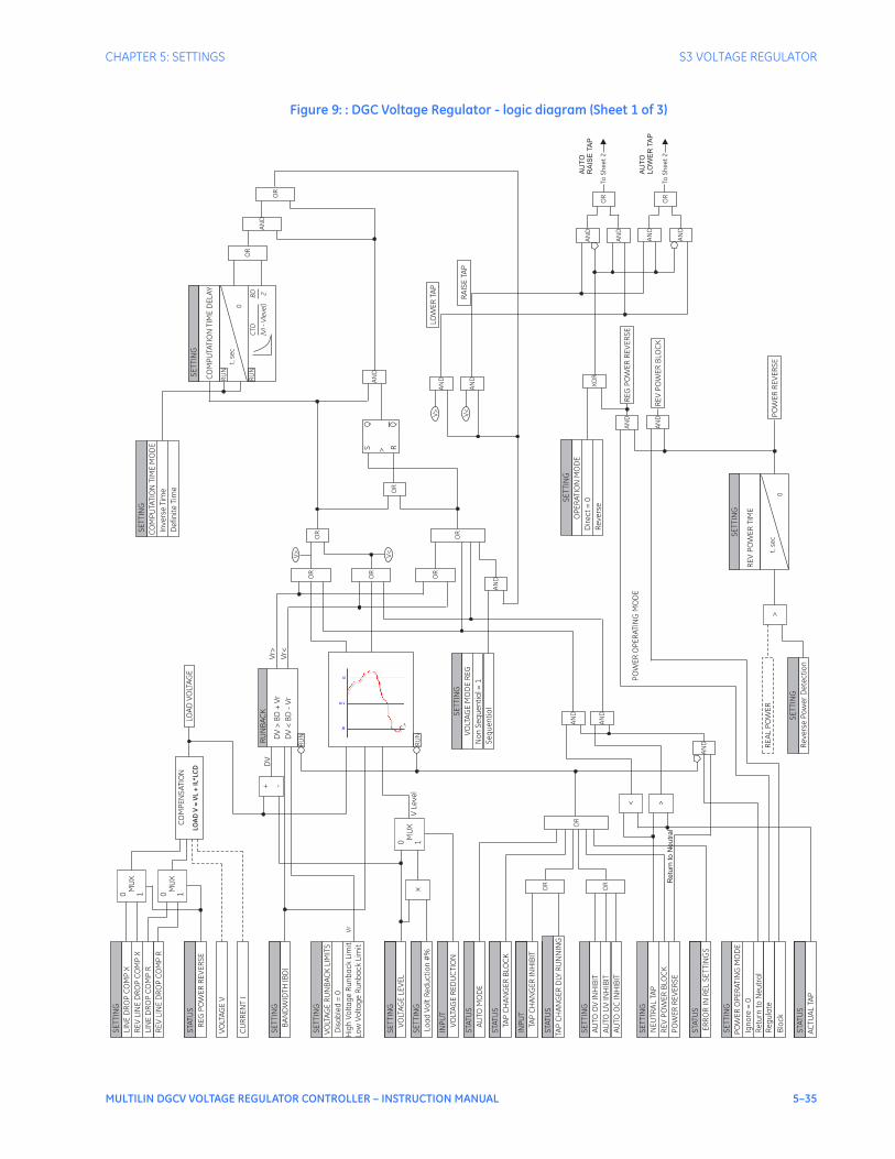
CHAPTER 5: SETTINGS S3 VOLTAGE REGULATOR
MULTILIN DGCV VOLTAGE REGULATOR CONTROLLER – INSTRUCTION MANUAL 5–35
Figure 9: : DGC Voltage Regulator - logic diagram (Sheet 1 of 3)S
ET
TIN
G
LIN
ED
RO
PC
OM
PX
RE
VLI
NE
DR
OP
CO
MP
X
LIN
ED
RO
PC
OM
PR
RE
VLI
NE
DR
OP
CO
MP
R
SE
TTI
NG
RE
GP
OW
ER
RE
VE
RS
E
VO
LTA
GE
V
CU
RR
EN
TI
STA
TUS
SE
TTI
NG
BA
ND
WID
TH(B
D)
SE
TTI
NG
SE
TTI
NG
VO
LTA
GE
RU
NB
AC
KLI
MIT
S
Dis
ab
led
=0
Hig
hV
olt
ag
eR
un
ba
ck
Lim
itLo
wV
olt
ag
eR
un
ba
ck
Lim
it
SE
TTI
NG
VO
LTA
GE
LEV
EL
SE
TTI
NG
SE
TTI
NG
Loa
dV
olt
Re
du
cti
on
#%
SE
TTI
NG
SE
TTI
NG
VO
LTA
GE
RE
DU
CTI
ON
INP
UT
SE
TTI
NG
AU
TOM
OD
E
STA
TUS
SE
TTI
NG
TAP
CH
AN
GE
RB
LOC
K
STA
TUS
SE
TTI
NG
SE
TTI
NG
SE
TTI
NG
TAP
CH
AN
GE
RIN
HIB
IT
SE
TTI
NG
SE
TTI
NG
INP
UT
SE
TTI
NG
TAP
CH
AN
GE
RD
LYR
UN
NIN
G
SE
TTI
NG
SE
TTI
NG
STA
TUS
SE
TTI
NG
AU
TOO
VIN
HIB
IT
AU
TOU
VIN
HIB
IT
AU
TOO
CIN
HIB
IT
SE
TTI
NG
ER
RO
RIN
RE
LS
ET
TIN
GS
SE
TTI
NG
SE
TTI
NG
STA
TUS
SE
TTI
NG
NE
UTR
AL
TAP
RE
VP
OW
ER
BLO
CK
PO
WE
RR
EV
ER
SE
SE
TTI
NG
PO
WE
RO
PE
RA
TIN
GM
OD
E
Ign
ore
=0
Blo
ck
Re
turn
toN
eu
tra
l
Re
gu
late
SE
TTI
NG
AC
TUA
LTA
P
SE
TTI
NG
SE
TTI
NG
STA
TUS
MU
X0 1
MU
X0 1
+ -
RU
NB
AC
K
DV
>B
D+
Vr
RU
N
MU
X0 1
x OR
OR
OR
><
AN
D
AN
D
AN
D
RU
N
OR
OR
OR
OR
AN
D
SE
TTI
NG
VO
LTA
GE
MO
DE
RE
G
No
nS
eq
ue
nti
al =
1
Se
qu
en
tia
l
OR
OR
V>
V<
S R>A
NDSE
TTI
NG
CO
MP
UTA
TIO
NTI
ME
DE
LA
Y
RU
N
RU
N
SE
TTI
NG
CO
MP
UTA
TIO
NTI
ME
MO
DE
Inve
rse
Tim
e
De
fin
ite
Tim
e
OR
AN
D
OR
t,se
c0
CT
D
[VI
-V
leve
l]
BD 2
LOA
DV
OLT
AG
EC
OM
PE
NS
ATI
ON
LO
AD
V=
VL
+IL
*L
CD
DV
<B
D-
Vr
Vr>
Vr<
DV
VLe
vel
Q Q
AN
D
AN
D
AN
D
AN
D
AN
D
AN
D
AN
D
AN
D
V>
V<
t,se
c0
RE
VP
OW
ER
TIM
E
SE
TTI
NG
SE
TTI
NG
Re
vers
eP
ow
er
De
tec
tio
n
RE
AL
PO
WE
R>
XO
R
PO
WE
RO
PE
RA
TIN
GM
OD
E
LOW
ER
TAP
RA
ISE
TAP
PO
WE
RR
EV
ER
SE
RE
VP
OW
ER
BLO
CK
RE
GP
OW
ER
RE
VE
RS
E
SE
TTI
NG
OP
ER
ATI
ON
MO
DE
Dir
ec
t=
0
Re
vers
eO
R
OR
ToS
he
et
2
ToS
he
et
2
AU
TO
RA
IS
ETA
P
AU
TO
LO
WE
RTA
P
Re
tu
rn
to
Ne
utra
l
Vr

5–36 MULTILIN DGCV VOLTAGE REGULATOR CONTROLLER – INSTRUCTION MANUAL
S3 VOLTAGE REGULATOR CHAPTER 5: SETTINGS
Figure 10: DGC Voltage Regulator - logic diagram (Sheet 2 of 3)
SC
AD
AC
om
ma
nd
s
Ra
ise
Tap
STA
TUS
MA
NU
AL
UV
INH
IBIT
MA
NU
AL
OC
INH
IBIT
TAP
CH
AN
GE
RD
LYR
UN
NIN
G
TAP
CH
AN
GE
RB
LOC
K
ER
RO
RIN
RE
LS
ET
TIN
GS
AN
D
AN
D
AN
D
AN
D
OR
OR 89
19
21
. cd
r(”
Sh
ee
t2
”)
INP
UT
TAP
CH
AN
GE
RIN
HIB
IT
Low
er
Tap
Re
mo
teIn
pu
ts
Re
mo
teR
ais
e
Re
mo
teLo
we
r
PB
/U
SB
Co
mm
an
ds
Ra
ise
Tap
Low
er
Tap
Re
mo
teC
om
ma
nd
s
Ma
nu
al
Au
to
Off
PB
/U
SB
Co
mm
an
ds
Ma
nu
al
Au
to
Off
Pu
shb
utt
on
Loc
al
Re
mo
te
>S R
Q Q
SE
T
CLR
>S R
Q Q
SE
T
CLR
AN
D
AN
D
AN
D
AN
D
AN
D
AN
D
AN
D
AN
D
AN
D
AN
D
AN
D
AN
D
OR
OR
OR
>S R
Q Q
SE
T
CLR
OR
OR
OR
>S R
Q Q
SE
T
CLR
>S R
Q Q
SE
T
CLR
OR
OR
OR
AN
D
Re
mo
teC
om
ma
nd
s
Ma
nu
al
Au
to
Off
Re
mo
teC
om
ma
nd
s
CO
MM
BLK
AU
TO
CO
MM
UN
BLO
CK
AU
TO
SE
TTI
NG
S
SA
VE
CO
MM
BLK
En
ab
led
=1 S
tate
CO
MM
FAIL
AL
AR
M
PO
WE
RLO
SS
AN
D
AN
D
AN
D
AN
DA
ND
OR
OR
OR
>S R
Q Q
SE
T
CLR
Sta
te(E
EP
RO
M)
CO
MM
BLK
AU
TOS
TATE
AN
D
STA
TUS
Ma
nu
al M
od
e
AN
D
AN
D
STA
TUS
Au
toM
od
e
LED
: LO
CA
L
LED
: RE
MO
TE
LED
: MA
NU
AL
LED
: AU
TO STA
TUS
Off
Mo
de
Se
tA
uto
LED
inb
linki
ng
mo
de
Au
toR
em
ote
PC
Pro
gra
ma
nd
SC
AD
A
Fro
mS
he
et
1
Fro
mS
he
et
1
AU
TOR
AIS
ETA
P
AU
TOLO
WE
RTA
P
LOW
ER
TAP
RA
ISE
TAP
ToS
he
et
3
ToS
he
et
3

CHAPTER 5: SETTINGS S3 VOLTAGE REGULATOR
MULTILIN DGCV VOLTAGE REGULATOR CONTROLLER – INSTRUCTION MANUAL 5–37
Figure 11: DGC Voltage Regulator - Manual Commands - logic diagram (Sheet 3 of 3)
SE
TPO
INT
MA
X/M
INLI
MIT
S
En
ab
le=
1, D
isa
ble
=0
SE
TPO
INT
MA
XTA
P
MIN
TAP
STA
TUS
AC
TUA
LTA
P
89
19
22
.cd
r(”
Sh
ee
t3
”)
OR
SE
TPO
INT
STA
TUS
TAP
CH
AN
GE
RD
LYR
UN
NIN
G
D >
Q
ME
MTA
P
M>=
0
A|A-
M| >1
RU
N
S >
Q
RQ
LTA
P
RTA
P
TAP
CH
AN
GE
RD
EL
AY
AN
D
S >
Q
RQ
5m
s
D >
Q
ME
MLO
AD
VO
LTA
GE
LOA
DV
OLT
AG
E
=1
AN
D
AN
D
= =
AN
D
AN
D
AN
D
AN
D
MA
XTA
PB
LOC
K
MIN
TAP
BLO
CK
OR
AN
D
STA
TUS
RA
ISE
BLO
CK
ED
Pu
lse
, s
S >
Q
RQ
CO
MM
AN
D
RE
SE
T/D
RA
GH
AN
DA
ND
CO
MM
AN
D
UN
BLO
CK
CH
AN
GE
UN
SU
CC
ES
SF
UL
INC
OM
P.S
EQ
. CH
AN
GE
AN
D
AN
D
AN
D
AN
D
AN
D AN
D
OR
OR
OR
CO
NTR
OL
CO
MM
AN
D
Co
un
ter
Low
er
Co
mm
an
d
CO
NTR
OL
CO
MM
AN
D
Co
un
ter
Ra
ise
Co
mm
an
d
S >
Q
RQ
S >
Q
RQ
TIM
ED
EL
AY
30
s
5m
s
TIM
ED
EL
AY
30
s
5m
s
<2
<2
AN
D
S >
Q
RQ
AN
D
S >
Q
RQ
RA
ISE
TAP
AN
D
STA
TUS
LOW
ER
BLO
CK
ED
Pu
lse
, s
LOW
ER
TAP
BLO
CK
RA
ISE
BLO
CK
LOW
ER
Fro
mS
he
et
2
Fro
mS
he
et
2
LO
WE
RTA
P
RA
IS
ETA
P
Ch
an
ge
Allo
we
d
RA
IS
ETA
P(to
RLY
1C
ON
TR
OL
)
LO
WE
RTA
P(to
RLY
2C
ON
TR
OL
)
CO
NTR
OL
CO
MM
AN
DC
ou
nte
rR
ais
eC
om
ma
nd
=0
CO
NTR
OL
CO
MM
AN
DC
ou
nte
rLo
we
rC
om
ma
nd
=0
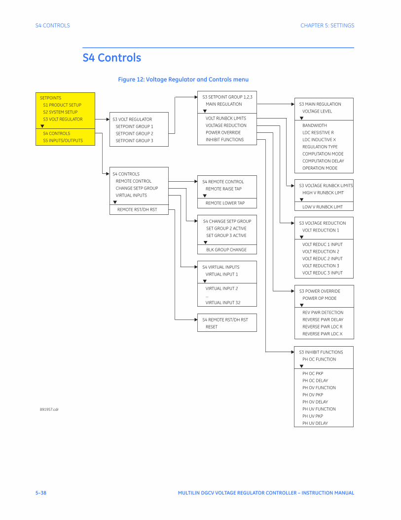
5–38 MULTILIN DGCV VOLTAGE REGULATOR CONTROLLER – INSTRUCTION MANUAL
S4 CONTROLS CHAPTER 5: SETTINGS
S4 Controls
Figure 12: Voltage Regulator and Controls menu
S3 VOLT REGULATOR
SETPOINT GROUP 1
SETPOINT GROUP 2
SETPOINT GROUP 3
SETPOINTS
S1 PRODUCT SETUP
S2 SYSTEM SETUP
S3 VOLT REGULATOR
S4 CONTROLS
S5 INPUTS/OUTPUTS
▼
S3 SETPOINT GROUP 1,2,3
MAIN REGULATION
VOLT RUNBCK LIMITS
VOLTAGE REDUCTION
INHIBIT FUNCTIONS
POWER OVERRIDE
▼
S4 REMOTE CONTROL
REMOTE RAISE TAP
REMOTE LOWER TAP
▼
891957.cdr
S4 CHANGE SETP GROUP
SET GROUP 2 ACTIVE
BLK GROUP CHANGE
SET GROUP 3 ACTIVE
▼
S4 VIRTUAL INPUTS
VIRTUAL INPUT 1
...
VIRTUAL INPUT 2
VIRTUAL INPUT 32
▼
S4
RESET
REMOTE RST/DH RST
S3 MAIN REGULATION
VOLTAGE LEVEL
BANDWIDTH
REGULATION TYPE
COMPUTATION MODE
COMPUTATION DELAY
OPERATION MODE
LDC RESISTIVE R
LDC INDUCTIVE X
▼
S3 VOLTAGE RUNBCK LIMITS
HIGH V RUNBCK LIMT
LOW V RUNBCK LIMT
▼
S3 VOLTAGE REDUCTION
VOLT REDUCTION 1
VOLT REDUC 1 INPUT
VOLT REDUCTION 2
VOLT REDUC 2 INPUT
VOLT REDUCTION 3
VOLT REDUC 3 INPUT
▼
S3 POWER OVERRIDE
POWER OP MODE
REV PWR DETECTION
REVERSE PWR DELAY
REVERSE PWR LDC R
REVERSE PWR LDC X
▼
S3 INHIBIT FUNCTIONS
PH OC FUNCTION
PH OC PKP
PH OC DELAY
PH OV FUNCTION
PH OV PKP
PH OV DELAY
PH UV FUNCTION
PH UV PKP
PH UV DELAY
▼
S4 CONTROLS
REMOTE CONTROL
CHANGE SETP GROUP
VIRTUAL INPUTS
REMOTE RST/DH RST
▼

CHAPTER 5: SETTINGS S4 CONTROLS
MULTILIN DGCV VOLTAGE REGULATOR CONTROLLER – INSTRUCTION MANUAL 5–39
Change settings groupThe Multilin DGCV has three identical settings groups - Groups 1, 2 , and 3 - for all Voltage Regulator elements. Switching between these three groups is available either automatically by assigning an input (contact, virtual, remote, flexlogic element), or manually through communications.Group 1 is the default setting group. The device can automatically switch from Group 1 Voltage Regulator elements to the other group elements, and vice versa, by setting up the switching conditions under “Change Setpoint Group”. Under some application conditions, it may be undesirable to change settings groups. In such cases, the user can set a condition under “BLK GROUP CHANGE”, where if asserted, the active settings group will stay active, even if the input configured to switch to the other settings group is asserted. For example if the active group was group 1 at any given time, and the input configured under “BLK GROUP CHANGE” is asserted, the relay will maintain settings group 1, even if the input “SET GROUP 2 (3) ACTIVE” is asserted. Visa versa, if the “BLK GROUP CHANGE” input is asserted, the relay will not switch from group 2/3 to group 1, even if the input under “SET GROUP 2 (3) ACTIVE” is de-asserted. The device will default to settings group 1, if both the input “SET GROUP 2 (3) ACTIVE” and the blocking input “BLK GROUP CHANGE” are de-asserted. Table group 3 of settings has a higher priority than the rest of settings groups. That means, if both “SET GROUP 2 ACTIVE” and “SET GROUP 3 ACTIVE” signals are maintained asserted at the same time, the Multilin DGCV will change to the table 3 of settings.The logic functionality takes into account this feature. PATH: S4 CONTROLS > CHANGE SPNT GROUP
SET GROUP 2 ACTIVE
Range: Off, Contact Input 1 to 12 (Order Code dependent), Virtual Input 1 to 32, Virtual Output 1 to 32Default: Off
This setting selects an input, used to change to Setpoint Group 2, when asserted. If no group change supervision is selected, the Setpoint Group 2 will stay active as long as the “SET GROUP 2 ACTIVE” input is asserted, and will revert to group 1, when this input is de-asserted.
SET GROUP 3 ACTIVE
Range: Off, Contact Input 1 to 12 (Order Code dependent), Virtual Input 1 to 32, Virtual Output 1 to 32Default: Off
This setting selects an input, used to change to Setpoint Group 3, when asserted. If no group change supervision is selected, the Setpoint Group 3 will stay active as long as the “SET GROUP 3 ACTIVE” input is asserted, and will revert to the default group, when this input is de-asserted.
BLOCK GROUP CHANGE
Range: Off, Contact Input 1 to 12 (Order Code dependent), Virtual Input 1 to 32, Virtual Output 1 to 32Default: Off
This setting defines an input that can be used to block changing settings groups. When the assigned input is asserted, changing from one settings group to the other one is blocked.

5–40 MULTILIN DGCV VOLTAGE REGULATOR CONTROLLER – INSTRUCTION MANUAL
S4 CONTROLS CHAPTER 5: SETTINGS
Figure 13: Changing Settings groups - logic diagram
Modes of VR operationThe Multilin DGCV has two modes of operation – Auto/Remote and Manual. The desired mode of operation is selected by toggling the AUTO/REM - MANUAL control pushbutton located on the faceplate of the regulator. The AUTO/REM - MANUAL pushbutton is active only if the Tap Changer control panel is set to Enabled. The green LED Enabled light indicates that the controls from the Tap Changer Control panel are enabled.
OR OR
AND
AND
AND
AND
OR
(De
fau
ltG
rou
p)
SE
TG
RO
UP
2A
CTI
VE
BLK
GR
OU
PC
HA
NG
E
SE
TG
RO
UP
3A
CTI
VE
Off
Off
Off
SE
TP
OIN
T
SE
TP
OIN
T
SE
TP
OIN
T
Use
Se
tpo
int
Gro
up
3
Use
Se
tpo
int
Gro
up
1
Use
Se
tpo
int
Gro
up
2
89
19
91
. cd
r

CHAPTER 5: SETTINGS S4 CONTROLS
MULTILIN DGCV VOLTAGE REGULATOR CONTROLLER – INSTRUCTION MANUAL 5–41
Manual operation Manual mode of operation is set by pressing the AUTO/REM – MANUAL control pushbutton. The MANUAL LED turns to green, indicating the selected mode of operation.In Manual mode, the voltage regulator controls the transformer output voltage by responding to manually performed raise or lower tap commands which use the RAISE and LOWER pushbuttons accordingly. When set to MANUAL mode, the tap changer can only be controlled using the faceplate RAISE and LOWER pushbuttons, or through the COMMANDS menu. In this mode automatic regulation and remote controls are blocked. The SCADA still receives data, but the SCADA control inputs are blocked.Pressing the RAISE pushbutton raises the tap position of the tap changer, whereas pressing the LOWER pushbutton lowers it .The operation of the following functions blocks the Manual controls:
• Overcurrent inhibit set to “Manual” or “Both”
• UnderVoltage inhibit set to “Manual” or “Both”
• TAP inhibit Input
• Disabled mode
• Incorrect TAP Changer value (No Tap Changer value or Out of Bounds)
• Tap Changer delay timer counting.
The Manual Raise command is blocked, if the Manual Overvoltage inhibit is active, or if the Maximum TAP position is reached. The Manual Lower command is blocked, if the Minimum TAP position is reached.The Manual command will be executed properly, and the voltage regulator will send a Raise or Lower command to the tap changer motor, if none of the inhibits is active. The digital output RLY 1 CONTROL or RLY 2 CONTROL, related to the Raise and the Lower tap commands will close, and will stay closed for the time specified in ‘Seal-in time’. The Multilin DGCV controller will wait until the specified Tap Changer Delay expires, and until the state of the Tap Changer Inhibit input (if programmed) drops down, before detecting the new tap position.The diagram below depicts the manual tap change logic.
NOTE
NOTE: The “Tap changer Delay” time shall be set longer than the "RLY Seal-in Time" for raise and lower outputs.
The LDC voltage compensation using the Main Regulation LDC or the Reverse Power LDC settings, is performed in Manual mode. The Voltage Reduction, Voltage Level, Runback Limits, UV/OV/OC, and Power Override functions do not apply in Manual mode, and the automatic Raise, or Lower Tap commands are blocked. Events and Target Messages are generated.

5–42 MULTILIN DGCV VOLTAGE REGULATOR CONTROLLER – INSTRUCTION MANUAL
S4 CONTROLS CHAPTER 5: SETTINGS
Figure 14: Manual tap change commands scheme - logic diagram
Auto/Remoteoperation
In Automatic/Remote mode, the Multilin DGCV controls the transformer tap changer automatically by applying the main and additional voltage controlling functions. The Multilin DGCV sends either a Raise, or a Lower command using the first two digital outputs – RLY 1 CONTROL for raising the tap, and RLY 2 CONTROL for lowering it , if Direct Operation mode is set. The decision to send a Raise, or Lower tap command, is performed upon comparison of the programmed Voltage Level, with the Measured Load Voltage adjusted by the programmed Resistance/Reactance Line Voltage Drop compensation. If the difference between the two voltages exceeds either the upper or the lower half of the programmed bandwidth during a period of time (programmed computation time), a Raise or Lower tap operation is initiated. In Automatic mode, the voltage regulator controls the load voltage using the following voltage regulating elements:
• Voltage Level
• Bandwidth
• Computation Time Delay
• Tap Changer Time Delay
• Input Voltage - measured
• Input Current - measured
• Line Drop Compensation R, X
• Runback Voltage limits (if enabled)
• Reverse Power (if enabled)
• Voltage Reduction (if “enabled”)
• Inhibitions (OC/OV/UV)
• TAP Changer position.
Both the Raise and Lower automatic commands will be blocked, if any of the following conditions occur:
• Overcurrent inhibit set to “Auto”, or “Both”
• Undervoltage inhibit set to “Auto”, or “Both”
• TAP Inhibit Input
• Reverse Power set to “Block” mode
• Reverse Power set to “Return to Neutral” mode with Neutral TAP reached
• Incorrect TAP position (No Tap position or tap position out of bounds)
TAP CHANGER INHIBITOR
Inhibit OC/UV
Incorrect Tap Changer
Inhibit OVOR
AND
AND
Raise CMD
Lower CMD
SETPOINT
TAP CHANGER DELAY
SETPOINT
TAP CHANGER DELAY
SETPOINT
TAP CHANGER DELAY
t
t
t
OR
RAISE (to Tap Changer)
LOWER (to Tap Changer)
891923.cdr

CHAPTER 5: SETTINGS S4 CONTROLS
MULTILIN DGCV VOLTAGE REGULATOR CONTROLLER – INSTRUCTION MANUAL 5–43
• Disabled Mode
• Manual mode
• Voltage below 20 Volts
• Tap Changer delay timer counting.
Two more inhibits apply to the Automatic Raise command:
• Auto Overvoltage inhibit
• Maximum TAP position reached.
One more inhibit applies to the Automatic Lower command:
• Minimum TAP position reached.
When in Automatic/Remote mode, the Multilin DGCV can be controlled remotely by SCADA, or an IED, via radio communication and Modbus, or by DNP protocol. The SCADA is configured to receive data and to write to the Multilin DGCV by mapping the Modbus or DNP addresses provided in this manual. The remote SCADA control over radio is inhibited by the DGC when it is set to Manual mode. Data monitoring is enabled. The Manual commands are enabled in Auto/Remote and Manual modes.
Sequential and Non-sequential tap
changer operation
Sequential or Non-Sequential tap change operation is selected from the main voltage regulation menu. When the voltage under regulation is detected to be higher or lower than the programmed voltage level bandwidth, the Voltage Regulator detects an “out of band” condition. In Non-sequential mode, the computation time delay applies to each Raise or Lower tap command. The regulator increases one tap at the time until the voltage is once again within the bandwidth. In Sequential mode, the computation time delay is timed out only for the first tap change. If the voltage is still "out of band," the control will continue issuing tap change commands without running through the Computation Time Delay, until the voltage is brought back into the band.The Computation Time Delay is settable to either a definite time with instantaneous reset, or an inverse time with linear reset.The Computation Time Delay is applied only when in Auto/Remote mode. The Computation Time Delay is not triggered during Manual operation. If a manual tap change command is issued during timing out of the Computation Time Delay, and a tap change is made (tap changer delay expired), but if the regulated voltage is still “out of band” the Computation Time delay will reset to start from the beginning. The Computation time delay is not triggered, if the regulated voltage exceeds any of the Runback Voltage limits when in Auto/Remote mode.
Direct and ReverseOperation Mode
(automatic operationsonly)
For Automatic operation, and “Direct” mode selection, the Raise tap command is executed by closing the RLY 1 CONTROL output, and the Lower tap command is executed by closing the RLY 2 CONTROL output. In “Reverse” Mode these two outputs are executed in exactly the same manner.
Remote RAISE andLOWER commands
The Multilin DGCV provides two additional settings for remote Raise and Lower commands by selection of a contact input, a virtual input, or a FlexLogic™ programmed virtual output. These operations can be executed only if the Voltage Regulator is in Auto/Remote mode.
Settings group control The DGC has three identical settings groups, each of which includes the settings of main regulation, runback limits, voltage reduction, power override, and inhibit functions. Only one of the three settings groups is active at any one time. Setpoint Group 1 is the active group by default. To activate any of the other two settings groups, the corresponding SET GROUP X ACTIVE setting must be programmed by selecting a contact input, a virtual input,

5–44 MULTILIN DGCV VOLTAGE REGULATOR CONTROLLER – INSTRUCTION MANUAL
S4 CONTROLS CHAPTER 5: SETTINGS
or a virtual output. If the programmed inputs for both Group 2 and Group 3 are detected as “high,” the Multilin DGCV applies the Group 2 settings. The active settings group can be locked active, by programming and energizing the input selected under BLK GROUP CHANGE.
Virtual inputs There are 32 Virtual Inputs that can be individually programmed to respond to Input commands entered via the relay keypad, or by using communication protocols. SETPOINTS > S4 CONTROLS > VIRTUAL INPUTS
VIRTUAL INPUT 1
Range: Off, OnDefault: Off
The state of each virtual input can be controlled under SETPOINTS > S4 CONTROL > VIRTUAL INPUTS menu. For this purpose, each of the virtual inputs selected for control need be “Enabled” under SETPOINTS > S5 INPUTS/OUTPUTS > VIRTUAL INPUTS, and its type “Self-Reset” or “Latched” specified.If Self-Reset type was selected, entering “On” command will lead to a pulse of one protection pass. To prolong the time of the virtual input pulse, one can assign it as a trigger source to an element with a dropout timer set to the desired pulse time. If “Latched” type is selected, the state of the virtual input will be latched, upon entering “On” command.Refer to the logic diagram below for more details.
Figure 15: Virtual Inputs Scheme - logic diagram
Remote Reset/Drag-Hands reset
This setting provides the selection of an input for remotely resetting the Multilin DGCV target messages and the triggered LEDs. Upon energizing of the programmed input, the Maximum and Minimum tap statistic data from the PRODUCT INFO menu will reset.
FlexLogic™The Multilin DGCV FlexLogic™ system, defines operators, and lists of operands. In essence, all the necessary information for custom built logic. The FlexLogic tool is accessible from the EnerVista DGCV Setup program under the SETPOINTS/ FLEXLOGIC menuAll Multilin DGCV digital signal states are represented by FlexLogic™ operands. Each operand is in one of two states: on (asserted, logic 1, or set), or off (de-asserted, logic 0, or reset). There is a FlexLogic™ operand for each contact input, contact output, communications command, control panel command, element trip, and element alarm, as well as many others.A list of FlexLogic™ operands and operators are sequentially processed once every 4.17 ms or 5 ms, depending on the power system frequency (60 Hz or 50 Hz) (TBC). When list processing encounters an operand, the value of that operand is placed in a first in - first out stack. When list processing encounters a calculation operator, the number of values
SETTING
V INPUT FUNCTION
Enabled = 1
Disabled = 0
AND“Virtual Input 1 to ON = 1”
“Virtual Input 1 to OFF = 1” AND
SETTING
V INPUT1 TYPE
Self-Reset
LatchedAND
LATCH
S
R
>
OR
SETTING
V INPUT1 NAME:(Operand)
V Input1 Status
891924.cdr

CHAPTER 5: SETTINGS S4 CONTROLS
MULTILIN DGCV VOLTAGE REGULATOR CONTROLLER – INSTRUCTION MANUAL 5–45
required for the calculation are removed from the stack, and the result of the operation is placed back on the stack. The operators are logic gates (for example, AND, OR, NOT), timers, latches, one-shots, and assignments. Assignment operators assign the value calculated by the preceding operators to a special class of operands called virtual outputs. Like any other operand, a virtual output can be used as an input to any operator –feedback to achieve seal-in is allowed. When list processing encounters an end operator, processing is stopped until the next processing cycle, at which time it restarts at the top of the list.Each contact output has a setpoint to specify the operand that drives the output. Any operand may be selected – selection of a virtual output is the means by which FlexLogic™ directly controls external equipment such as the motor contactors.The operators used in FlexLogic™ conform to the following rules:
• 512 lines for bulding logic are available in the FlexLogic tool. All lines are executed every 1 / 4 power system cycle (4.17 ms. or 5 ms) (TBC).
• A virtual output may only be assigned once within the FlexLogic environment. An unassigned virtual output will have a value of off.
• A maximum of thirty (32) general purpose timers (timers 1 through 32) are available for configuration. Each timer may only be used once within the FlexLogic environment.
• A maximum of thirty (30) one-shots are allowed.
• A maximum of 16 latches are supported.
FlexLogic™ operands The FlexLogic™ operands available in the Multilin DGCV are listed below.
Control operands: Group 1 Active OP......................................Activates when Setting Group 1 is applied.Group 1 Active DPO ..................................Activates when the Multilin DGCV is switched to a Setting Group
different from Group 1.Group 2 Active OP......................................Activates when Setting Group 2 is applied.
Operator Inputs Description
<operand> none The output value is the value of the named <operand>.
NOT 1 The output value is “on” if and only if any of the input values are “off”.
OR 2 to 16 The output value is “on” if and only if any of the input values are “on”.
AND 2 to 16 The output value is “on” if and only if all of the input values are “on”.
NOR 2 to 16 The output value is “on” if and only if all of the input values are “off”.
NAND 2 to 16 The output value is “on” if and only if any of the input values are “off”.
XOR 2 The output value is “on” if and only if one input value is “on” and the other input value is “off”.
TIMER 1 The output value is “on” if the input value has been “on” for the set pickup time. Once the output value is “on”, it remains “on” until the input value has been “off” for the set dropout time.
LATCH 2 The output value is the state of a reset-dominant volatile bi-stable latch, where the first input value is the set input , and the second input value is the reset input.
Positive-one-shot 1 The output value is “on” for one processing cycle following an off-to-on transition of the input value.
Negative-one-shot 1 The output value is “on” for one processing cycle following an on-to-off transition of the input value.
Dual-one-shot 1 The output value is “on” for one processing cycle following either an on-to-off or off-to-on transition of the input value.
ASSIGN <operand> 1 The input value is assigned to the named operand. There is otherwise no output value.
END none The first END encountered terminates the current processing cycle.

5–46 MULTILIN DGCV VOLTAGE REGULATOR CONTROLLER – INSTRUCTION MANUAL
S4 CONTROLS CHAPTER 5: SETTINGS
Group 2 Active DPO..................................Activates when the Multilin DGCV is switched to a Setting Group different from Group 2.
Group 3 Active OP .....................................Activates when Setting Group 3 is applied.Group 3 Active DPO..................................Activates when the Multilin DGCV is switched to a Setting Group
different from Group 3.Auto/Remote ...............................................Activates when the Multilin DGCV is switched to Auto/Remote
mode.Manual............................................................Activates when the Multilin DGCV is switched to Manual mode.Reverse Power OP .....................................Activates when the Reverse Power element operates.Reverse Power DPO..................................Activates when the Reverse Power level drops below the pickup
level.Reverse Power PKP...................................Activates when the Reverse Power level rises above the pickup
level.Auto Raise Tap ............................................Activates when the Tap is raised in Auto mode.Manual Raise Tap ......................................Activates when the Tap is raised in Manual mode.Auto Lower Tap ..........................................Activates when the Tap is lowered in Auto mode.Manual Lower Tap.....................................Activates when the Tap is lowered in Manual mode.High V Runback OP...................................Activated when the computed load voltage is above the High
Runback voltage limit.High V Runback DPO ...............................Activated when the computed load voltage becomes lower
than the High Runback voltage limit.Low V Runback OP....................................Activated when the computed load voltage is below the Low
Runback voltage limit.Low V Runback DPO.................................Activated when the computed load voltage becomes higher
than the Low Runback voltage limit.Volt Reduction 1 OP..................................Activates when Voltage Reduction 1 has been activated.Volt Reduction 1 DPO...............................Activates when Voltage Reduction 1 is deactivated.Volt Reduction 2 OP..................................Activates when Voltage Reduction 2 has been activated.Volt Reduction 2 DPO...............................Activates when Voltage Reduction 2 is deactivated.Volt Reduction 3 OP..................................Activates when Voltage Reduction 3 has been activated.Volt Reduction 3 DPO...............................Activates when Voltage Reduction 3 is deactivated.Reverse Power Reg OP............................Activates when reverse power is detected, with Power
Operation Mode set as “Regulate”.Reverse Power Reg DPO.........................Activates when the detected reverse power becomes lower
than the programmed Reverse Power detection level, with Power Operation Mode set as “Regulate”.
Rev Pwr Block OP.......................................Activated when reverse power is detected, with Power Operation Mode set as “Block”.
Rev Pwr Block DPO ...................................Activates after the reverse power is below the reverse power detection level, with Power Operation Mode set as “Block”.
Rev Pwr To Ntl OP......................................Activates when Power Override element set to “Return to Neutral” mode operates.
Rev Pwr To Ntl DPO...................................Activates after the reverse power is detected below the reverse power pickup level, with Power Operation Mode set as “Return to Neutral”.
Input/Output Operands:Contact Input 1 (2 to X) On ....................Asserted when the respective Contact Input is activated.Contact Input 1 (2 to X) Off....................Asserted when the respective Contact Input is deactivated.Contact Output 1 (2 to X) On ................Asserted when the respective Contact Output is activated.Contact Output 1 (2 to X) Off ................Asserted when the respective Contact Output is deactivated.

CHAPTER 5: SETTINGS S4 CONTROLS
MULTILIN DGCV VOLTAGE REGULATOR CONTROLLER – INSTRUCTION MANUAL 5–47
VI1 (VI1 to VO32) On..................................Asserted when the respective Virtual Input is activated.VI1 (VI2 to VI32) Off....................................Asserted when the respective Virtual Input is deactivated.VO1 (VO2 to VO32) On..............................Asserted when the respective Virtual Output is activated.VO1Off to VO32 Off ...................................Asserted when the respective Virtual Output is deactivated.
Alarm Operands:Any Alarm OP...............................................Activates when any Alarm Operand is asserted (logic 1).Not Configured ...........................................Activates when the DGC status is “Not Configured” under
INSTALLATION/PRODUCT STATUS.Self-test Alarm OP .....................................Activates when the CB detects a Self-test error.Self-test Alarm DPO..................................Activates when the Self-test error is resolved. Comm Fail Alarm OP ................................Activates when the communication channel fails.Comm Fail Alarm DPO.............................Activates when the communication channel starts to operate
properly. Max Taps Total OP.....................................Activates when the total Tap operations have been reached. Max Taps Total DPO..................................Activates when the counter is cleared using the counter clear
command or is cleared automatically at 12:00 midnight. Max Taps/Day OP ......................................Activates when the maximum Tap operations per day have
been reached. Max Taps/Day DPO...................................Activates when the counter is cleared using the counter clear
command, or is cleared automatically at 12:00 midnight. Min Tap Alarm OP ......................................Activates when the Tap changer reaches the minimum tap. Min Tap Alarm DPO...................................Activates when the Tap changer moves away from the
minimum tap position. Max Tap Alarm OP.....................................Activates when the Tap changer reaches the maximum tap. Max Tap Alarm DPO..................................Activates when the Tap changer moves away from the
maximum tap position. Out Of Band OP...........................................Activates when the computed load voltage level is beyond the
low or high bandwith level. Out Of Band DPO .......................................Activates when the computed load voltage level goes back
from Out Of Band to within the programmed bandwidth.
Block and Inhibit Operands:Group Change Block OP .........................Activates when the input programmed to block group change
is energized.Group Change Block DPO......................Activates when the input programmed to block group change
is de-energized.Any Inhibit OP ..............................................Activates when any of the blocks (inhibits) operates.Tap Changer Inhibit OP ...........................Activates when the programmed Tap Changer Inhibit input is
energized.Tap Changer Inhibit DPO........................Activates when the Tap Changer Inhibit input is de-energized.Unsuc Tap Chge OP ..................................Activates when no tap change is detected upon the tap change
command.Unsuc Tap Chge DPO...............................Activates upon the tap change being corrected.Incomp Tap Seq OP...................................Activates when tap position does not follow the increment/
decrement of 1 tap per command.Incomp Tap Seq DPO ............................... Activates upon detection of the correct sequence.OV Auto Inhibit PKP...................................Activates when the Multilin DGCV is in Auto or Both mode, and
the OV inhibit element picks-up.OV Auto Inhibit OP.....................................Activated when the Multilin DGCV is in Auto or Both mode, and
the OV inhibit operates.

5–48 MULTILIN DGCV VOLTAGE REGULATOR CONTROLLER – INSTRUCTION MANUAL
S4 CONTROLS CHAPTER 5: SETTINGS
OV Auto Inhibit DPO ................................. Activated when the Multilin DGCV is in Auto or Both mode, and the measured voltage drops below the programmed OV inhibit element pickup.
OV Manual Inhibit PKP.............................Activates when the Multilin DGCV is in Manual or Both mode, and the OV inhibit element picks-up.
OV Manual Inhibit OP...............................Activated when the Multilin DGCV is in Manual or Both mode, and the OV inhibit operates.
OV Manual Inhibit DPO............................ Activated when the Multilin DGCV is in Manual or Both mode, and the measured voltage drops below the programmed OV inhibit element pickup
UV Auto Inhibit PKP...................................Activates when the Multilin DGCV is in Auto or Both mode, and the UV inhibit element picks-up.
UV Auto Inhibit OP.....................................Activated when the Multilin DGCV is in Auto or Both mode, and the UV inhibit operates.
UV Auto Inhibit DPO.................................. Activated when the Multilin DGCV is in Auto or Both mode, and the measured voltage rises above the programmed UV inhibit element pickup.
UV Manual Inhibit PKP.............................Activates when the Multilin DGCV is in Manual or Both mode, and the UV inhibit element picks-up.
UV Manual Inhibit OP...............................Activated when the Multilin DGCV is in Manual or Both mode, and the UV inhibit operates.
UV Manual Inhibit DPO............................ Activated when the Multilin DGCV is in Manual or Both mode, and the measured voltage rises above the programmed UV inhibit element pickup.
OC Auto Inhibit PKP ..................................Activates when the Multilin DGCV is in Auto or Both mode, and the OC inhibit element picks-up.
OC Auto Inhibit OP.....................................Activated when the Multilin DGCV is in Auto or Both mode, and the OC inhibit operates.
OC Auto Inhibit DPO ................................. Activated when the Multilin DGCV is in Auto or Both mode, and the measured current drops below the programmed OC inhibit element pickup.
OC Manual Inhibit PKP.............................Activates when the Multilin DGCV is in Manual or Both mode, and the OC inhibit element picks-up.
OC Manual Inhibit OP...............................Activated when the Multilin DGCV is in Manual or Both mode, and the OC inhibit operates.
OC Manual Inhibit DPO ........................... Activated when the Multilin DGCV is in Manual or Both mode, and the measured current drops below the programmed OC inhibit element pickup.

CHAPTER 5: SETTINGS S5 INPUTS/OUTPUTS
MULTILIN DGCV VOLTAGE REGULATOR CONTROLLER – INSTRUCTION MANUAL 5–49
S5 Inputs/Outputs
Figure 16: Inputs/Outputs menu
Contact inputsThe Multilin DGCV is equipped with six (6) contact inputs, which can be used to provide a variety of functions such as for circuit breaker control, external trips, blocking of protection elements, etc. A further six (6) contact inputs can be added with the purchase of another IO_C board (see the Order Codes section). All contact inputs are wet type contacts (refer to the typical wiring diagram) that require an external AC or DC voltage source.
SETPOINTS
S1 PRODUCT SETUP
S2 SYSTEM SETUP
S3 VOLT REGULATOR
S4 CONTROLS
S5 INPUTS/OUTPUTS
▼
891959.cdr
S5 INPUTS/OUTPUTS
OUTPUT RELAYS
CONTACT INPUTS
VIRTUAL INPUTS
S5 CONTACT INPUTS
CONTACT INPUT 1
CONTACT INPUT 2
...
CONTACT INPUT 12
▼
S4 VIRTUAL INPUTS
VIRTUAL INPUT 1
VIRTUAL INPUT 2
VIRTUAL INPUT3
VIRTUAL INPUT4
...
VIRTUAL INPUT 32
▼
S5 OUTPUT RELAYS
RLY 1 CONTROL
RLY 2 CONTROL
RLY 3 AUXILIARY
RLY 4 AUXILIARY
RLY 5 AUXILIARY
...
RLY x AUXILIARY
▼
S5 RLY 1 CONTROL
NAME
RLY 1 RAISE TAP
SEAL-IN TIME
▼
S5 RLY 2 CONTROL
NAME
RLY 2 LOWER TAP
SEAL-IN TIME
▼
S5 RLY 3 AUXILIARY
NAME
FUNCTION
OUTPUT TYPE
OPERATION
▼
S5 VIRTUAL INPUT 1
VI 1
VI 1
NAME
FUNCTION
VI 1 TYPE
▼
S5 VIRTUAL INPUT 32
VI 32
VI 32
NAME
FUNCTION
VI 32 TYPE
▼

5–50 MULTILIN DGCV VOLTAGE REGULATOR CONTROLLER – INSTRUCTION MANUAL
S5 INPUTS/OUTPUTS CHAPTER 5: SETTINGS
PATH: SETPOINTS > S5 INPUTS/OUTPUTS > CONTACT INPUTS
CONTACT INPUT 1
Range: Eighteen CharactersDefault: Input 1
CONTACT INPUT 2
Range: Eighteen CharactersDefault: Input 2
CONTACT INPUT X [3 to 12]
Range: Eighteen CharactersDefault: Input X
Each of the contact inputs can be named to reflect the function it represents within the application. Up to 18 alpha-numeric characters are available for names.
Output relaysThe is equipped with seven electromechanical output relays: 2 form A relays (Relay 1 - Raise Tap, and Relay 2 - Lower Tap), and 4 form C relays (IO_D Card - see Order Codes section).
Output Relay 1 "RaiseTap"
PATH: SETPOINTS > S5 INPUTS/OUTPUTS > OUTPUT RELAYS > RLY 1 RAISE TAP
SEAL IN TIME
Range: 0.00 to 9.99 s in steps of 0.01 sDefault: 0.50 s
This setting defines the time to be added to the reset time of the Output Relay 1 Raise Tap output, thus extending its pulse width.
Output Relay 2 "LowerTap"
PATH: SETPOINTS > S5 INPUTS/OUTPUTS > OUTPUT RELAYS > RLY2 LOWER TAP
SEAL IN TIME
Range: 0.00 to 9.99 s in steps of 0.01 sDefault: 0.50 s
This setting defines the time to be added to the reset time of the Output Relay 2 Lower Tap output, thus extending its pulse width.
Auxiliary OutputRelays 3 to 7
Each auxiliary relay can be selected as either Self-reset, or Latched. If the Self-Reset type is selected, the output relay will be energized as long as the element is in operating mode and will reset when the element drops out. If the Latched type is selected, the output relay will stay energized, after the element dropout, and will be de-energized upon the reset command. If an auxiliary output is only required while the activating condition is present, select Self-Reset. Once an activating condition disappears, the auxiliary relay returns to the non-active state and the associated message automatically clears. To ensure all auxiliary function conditions are acknowledged, select Latched.PATH: SETPOINTS > S5 INPUTS/OUTPUTS > OUTPUT RELAYS > RLY 3(7) AUXILIARY
OUTPUT TYPE
Range: Self Reset, LatchedDefault: Self Reset

CHAPTER 5: SETTINGS S5 INPUTS/OUTPUTS
MULTILIN DGCV VOLTAGE REGULATOR CONTROLLER – INSTRUCTION MANUAL 5–51
Virtual inputsThere are 32 Virtual Inputs that can be individually programmed to respond to Input commands entered via the relay keypad, or by using communication protocols. Virtual Input programming begins with enabling the Virtual Input function and selecting the Virtual Input Type - Self-Reset or Latched - under SETPOINTS > S5 INPUTS/OUTPUTS. Next, under SETPOINTS > S4 CONTROLS > S4 VIRTUAL INPUTS, the user assigns either an On or an Off command to the Virtual Input enabled earlier.Referring to the Virtual Inputs logic diagram below, a Virtual Input type can be selected to be either Self-Reset, or Latched. When Self-Reset is selected, and the command On is executed, the virtual input is evaluated as a pulse at rate of one protection pass. When the Latched type is selected, the On state of the Virtual Input will be latched. SETPOINTS > S5 INPUTS/OUTPUTS > VIRTUAL INPUTS
VI x NAME
Range: 18 CharactersDefault: Virtual IN x
This setting defines a programmable name for the Virtual Input.
VI x FUNCTION
Range: Disabled/EnabledDefault: Disabled
The Virtual Input is enabled and ready to be triggered when set to Enabled.
VI x TYPE
Range: Self-Reset, LatchedDefault: Self-reset
When the Self-Reset type is selected, the Virtual Input will be evaluated for one protection pass only, upon “On” initiation and it will reset. When the Latched type is selected, the virtual input will keep the state “On” until reset command “Off” is initiated.
NOTE
NOTE: See also the Virtual Inputs section under S4 CONTROLS, on how to trigger a virtual input signal state.
Figure 17: Virtual Inputs Scheme - logic diagram
SETTING
V INPUT FUNCTION
Enabled = 1
Disabled = 0
AND“Virtual Input 1 to ON = 1”
“Virtual Input 1 to OFF = 1” AND
SETTING
V INPUT1 TYPE
Self-Reset
LatchedAND
LATCH
S
R
>
OR
SETTING
V INPUT1 NAME:(Operand)
V Input1 Status
891924.cdr

5–52 MULTILIN DGCV VOLTAGE REGULATOR CONTROLLER – INSTRUCTION MANUAL
S5 INPUTS/OUTPUTS CHAPTER 5: SETTINGS

MULTILIN DGCV VOLTAGE REGULATOR CONTROLLER – INSTRUCTION MANUAL 6–1
Multilin DGCV Voltage Regulator Controller
Chapter 6: Commands
Digital Energy
Commands
The Voltage Regulator LOWER/RAISE control can be used in three different ways:
• RAISE and LOWER commands from the DGC faceplate pushbuttons or the DGC menu
• Remote RAISE and LOWER control upon energizing of assigned inputs under CONTROLS/REMOTE CONTROL
• RAISE and LOWER commands over serial DNP.
NOTE
NOTE: None of the methods for raising or lowering the cap bank will be executed if the Multilin DGCV control is disabled - i.e. the pushbutton ENABLED/DISABLED is pressed to select DISABLED mode, with the “Disabled” LED lit . The toggling between Auto/Remote, and Manual mode using the corresponding pushbutton is disabled.
RAISE and LOWER from the DGC faceplate pushbuttons or the DGC menuThe RAISE and LOWER pushbuttons from the Multilin DGCV faceplate will be active in either Manual or Auto mode, provided the Multilin DGCV control is enabled (the “Enabled" LED is lit), and no other blocks or switching inhibits are applied.
Figure 1: DGC faceplate pushbuttons
PATH: MAIN MENU > COMMANDS
RAISE
Range: No, YesDefault: No
This setting is used to open the Voltage Regulator from the DGC menu. Selecting “Yes” and pressing the ENTER pushbutton from the keypad initiates an RAISE pulse command. The “Yes” command pulse is set to 50ms.
6–2 MULTILIN DGCV VOLTAGE REGULATOR CONTROLLER – INSTRUCTION MANUAL
CHAPTER 6: COMMANDS
LOWER
Range: No, YesDefault: No
This setting is used to lower the Voltage Regulator from the DGC menu. Selecting “Yes” and pressing the ENTER pushbutton from the keypad initiates a LOWER pulse command. The “Yes” command pulse is set to 50ms.
RESET
Range: No, YesDefault: Disabled
This setting is used to reset activated LEDs and any alarms or target messages. Selecting “Yes” and pressing the ENTER pushbutton from the keypad initiates a RESET command. The “Yes” command pulse is set to 50ms.
The Drag Hand Reset setting provides for the selection of an input for remotely resetting the Max and Min tap indications from the tap position indicator. Upon energizing the programmed input, the Maximum and Minimum tap statistic data from the PRODUCT INFO menu will also reset. The command energizes a drag-hand output relay, which when wired to the tap position indicator, applies ~120 V AC to the drag-hands coils.
Remote RAISE and LOWER upon energizing of inputs selected under CONTROLS/REMOTE CONTROLThe Voltage Regulator RAISE and LOWER commands received via the selected inputs, are executed if the DGC Voltage Regulator control is enabled (the “Enabled” LED is lit) and the selected control mode is Auto/Remote (the Auto/Remote LED is lit). The remote RAISE and LOWER commands are blocked if the “Manual” control mode is selected (the “Manual” LED is lit).PATH: CONTROLS > REMOTE CONTROL
REMOTE RAISE
Range: Off, Contact Input, Virtual Input, Virtual OutputDefault: Off
This setting selects an input from a list of inputs, which, when asserted, energizes the “relay #1 Control” output, wired to raise (switch out) the Voltage Regulator. When the selected input is asserted, the “relay #1 control" contact is energized and stays energized until the input drops off.
REMOTE LOWER
Range: Off, Contact Input, Virtual Input, Virtual OutputsDefault: Disabled
This setting selects an input from a list of inputs, which, when asserted, energizes the “relay #2 Control” output, wired to lower (switch in) the Voltage Regulator. When the selected input is asserted, the “relay #2 control contact is energized and stays energized according to the times selected per the Voltage Regulator control logic.
REMOTE RESET
Range: No, Off, Contact Input, Virtual Input, Virtual OutputDefault: Off
This setting is used to reset the LEDs, alarms, and target messages generated during some abnormal Voltage Regulator condition. The setting provides for the selection of an input from a list of inputs, that performs the RESET action upon activation.
RAISE and LOWER commands over DNP addressing, using radioThe RAISE and LOWER command can be initiated from a SCADA or an IED via radio communication. The controlling device maps an OPEN or a CLOSE command to its binary outputs, and transmits them via radio communication to the DGC Voltage Regulator controller. Upon reception, the DGC Voltage Regulator controller executes the appropriate action. The DGC Voltage Regulator controller executes the received commands if the DGC

CHAPTER 6: COMMANDS
MULTILIN DGCV VOLTAGE REGULATOR CONTROLLER – INSTRUCTION MANUAL 6–3
Voltage Regulator control is enabled (the “Enabled" LED is lit), and the selected control mode is set to Auto/Remote (the "Auto/Remote" LED is lit). The remote RAISE and LOWER commands via radio are blocked if “Manual” control mode is selected (the “Manual” LED is lit).

6–4 MULTILIN DGCV VOLTAGE REGULATOR CONTROLLER – INSTRUCTION MANUAL
CHAPTER 6: COMMANDS
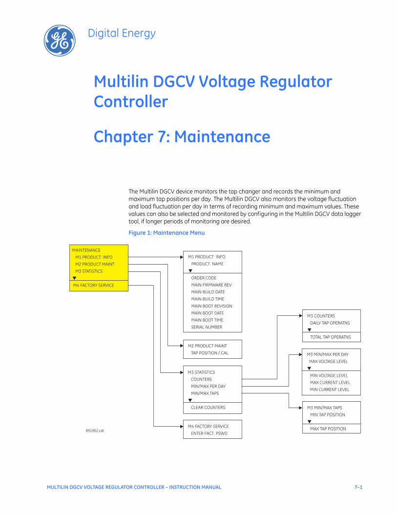
MULTILIN DGCV VOLTAGE REGULATOR CONTROLLER – INSTRUCTION MANUAL 7–1
Multilin DGCV Voltage Regulator Controller
Chapter 7: Maintenance
Digital Energy
Maintenance
The Multilin DGCV device monitors the tap changer and records the minimum and maximum tap positions per day. The Multilin DGCV also monitors the voltage fluctuation and load fluctuation per day in terms of recording minimum and maximum values. These values can also be selected and monitored by configuring in the Multilin DGCV data logger tool, if longer periods of monitoring are desired.
Figure 1: Maintenance Menu
M4 FACTORY SERVICE
ENTER FACT: PSWD
M1 PRODUCT INFO
PRODUCT NAME
ORDER CODE
MAIN FIRMWARE REV
MAIN BUILD DATE
MAIN BUILD TIME
MAIN BOOT REVISION
MAIN BOOT DATE
MAIN BOOT TIME
SERIAL NUMBER
▼
MAINTENANCE
M1 PRODUCT INFO
M2 PRODUCT MAINT
M4 FACTORY SERVICE
M3 STATISTICS
▼
891962.cdr
M3 MIN/MAX PER DAY
MAX VOLTAGE LEVEL
MIN VOLTAGE LEVEL
MAX CURRENT LEVEL
MIN CURRENT LEVEL
▼
M3 COUNTERS
DAILY TAP OPERATNS
TOTAL TAP OPERATNS
▼
M3 STATISTICS
COUNTERS
MIN/MAX PER DAY
MIN/MAX TAPS
CLEAR COUNTERS
▼
M3 MIN/MAX TAPS
MIN TAP POSITION
MAX TAP POSITION
▼
M2 PRODUCT MAINT
TAP POSITION / CAL
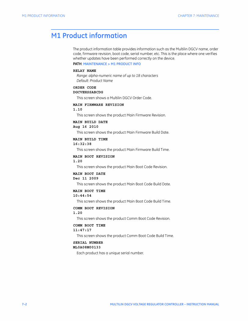
7–2 MULTILIN DGCV VOLTAGE REGULATOR CONTROLLER – INSTRUCTION MANUAL
M1 PRODUCT INFORMATION CHAPTER 7: MAINTENANCE
M1 Product information
The product information table provides information such as the Multilin DGCV name, order code, firmware revision, boot code, serial number, etc. This is the place where one verifies whether updates have been performed correctly on the device.PATH: MAINTENANCE > M1 PRODUCT INFO
RELAY NAME
Range: alpha-numeric name of up to 18 characters Default: Product Name
ORDER CODEDGCVEHSSABCDG
This screen shows a Multilin DGCV Order Code.
MAIN FIRMWARE REVISION1.10
This screen shows the product Main Firmware Revision.
MAIN BUILD DATEAug 16 2010
This screen shows the product Main Firmware Build Date.
MAIN BUILD TIME16:32:38
This screen shows the product Main Firmware Build Time.
MAIN BOOT REVISION1.20
This screen shows the product Main Boot Code Revision.
MAIN BOOT DATEDec 11 2009
This screen shows the product Main Boot Code Build Date.
MAIN BOOT TIME10:44:54
This screen shows the product Main Boot Code Build Time.
COMM BOOT REVISION1.20
This screen shows the product Comm Boot Code Revision.
COMM BOOT TIME11:47:17
This screen shows the product Comm Boot Code Build Time.
SERIAL NUMBERML0A08M00133
Each product has a unique serial number.

CHAPTER 7: MAINTENANCE M3 STATISTICS
MULTILIN DGCV VOLTAGE REGULATOR CONTROLLER – INSTRUCTION MANUAL 7–3
M3 Statistics
CountersThere are two tap changer counters under this tab: DAILY TAP OPERATIONS, and TOTAL TAP OPERATIONS. The DAILY TAP OPERATIONS counter provides information on how many tap operations were made during day period of 24 hours starting from 12:00 am, beginning of the day, until 12:00 am, the beginning of the next day. The counter clears to 0 at 12:00 midnight for each following day. Otherwise this counter can be cleared at any time by issuing a CLEAR COUNTER command.The counter TOTAL TAP OPERATIONS accumulates the tap changer operations every time the tap changer moves the tap. This counter is not cleared on a per day basis. The counter will stop increasing the number of total tap operations beyond 10000. This counter can be cleared at any time by issuing a CLEAR COUNTER command. MIN/MAX per DayThe MIN/MAX PER DAY monitors the minimum and maximum line voltage, as well as the minimum and maximum loads per day, and records these values for the user’s information. These values can be also monitored through the VR Data Logger over a period of time greater than one day. The MIN and MAX information is recorded during a day period of 24 hours starting from 12:00 am, beginning of the day, until 12:00 am, the beginning of the next day. These minimum and maximum values are reset at 12:00 midnight for the following day period. At that time, they are reset to the present line voltage and load current. MIN/MAX TapThe MIN/MAX TAP provides information on the lowest (minimum), and the highest (maximum) tap position reached by the tap changer during one 24-hour day period. These values can be also monitored through the VR Data Logger over a period of time greater than one day. The MIN and MAX tap information is recorded during a 24-hour period of time, starting at 12:00 am, beginning of the day, until 12:00 am, the beginning of the next day. These minimum and maximum values are reset at 12:00 midnight for the following day period. At that time, they are reset to the present tap position.

7–4 MULTILIN DGCV VOLTAGE REGULATOR CONTROLLER – INSTRUCTION MANUAL
M3 STATISTICS CHAPTER 7: MAINTENANCE