volt / var regulation in energy transmission systems using
TRANSCRIPT
BALKAN JOURNAL OF ELECTRICAL & COMPUTER ENGINEERING, Vol. 7, No. 4, October 2019
Copyright © BAJECE ISSN: 2147-284X http://dergipark.gov.tr/bajece
Abstract— To ensure energy continuity in the interconnected
power systems, production and consumption amounts should be
in balance, and that can be possible by providing constant voltage
and frequency. Otherwise, undesirable large dynamic oscillations,
voltage collapse may occur, and the quality of the electrical energy
deteriorates. In this study, the power system of the Denizli Region
in the Western Mediterranean Region is modeled using realistic
national data. The simulation study is carried out to obtain the
voltages, active and reactive powers of buses in the case of no-fault
and fault occurrence. Using FACTS (Flexible Alternating Current
Transmission Systems) technology such as SVC and STATCOM,
the power systems can be controlled, and the carrying capacities
can be improved within specified limits. Facts devices are capable
of producing and consuming reactive power depending on
immediate needs, safe and operating flexibility, and having a high
reaction time in the simulation studies. The maximum load limits
are increased, and the control of the power system is facilitated.
STATCOM provides 31.09 % more achievement with respect to SVC
device at energy production and consumption rates for the modeled
pilot region. The reliability of the power system has been increased
against a voltage collapse, thanks to the SVC and STATCOM
controllers. Furthermore, the voltage stability of the generator is
also raised, and correspondingly the capacity of the power system
enhances. The results are compared to the existing system, and the
obtained improvements may be assessed for the enhancement of
the interconnected network grid of Turkey.
Index Terms—Power System Analysis, Statcom, Svc, Facts,
Voltage Regulation, Reactive Power Regulation
I. INTRODUCTION
OWER ELECTRONICS-BASED Flexible Alternating Current
Transmission Systems (FACTS) are used for active power,
reactive power, impedance, and voltage control in power
systems. HAMZA FEZA CARLAK, is with Department of Electrical and Electronics Engineering Akdeniz University, Antalya, Turkey, (e-mail: [email protected]).
https://orcid.org/0000-0002-8561-4591
ERGİN KAYAR, is with Department of Electrical and Electronics Engineering Akdeniz University, Antalya, Turkey, (e-mail: [email protected]).
https://orcid.org/0000-0002-7356-2165 Manuscript received July 23, 2019; accepted October 16, 2019. DOI: 10.17694/bajece.595761
In the recent years, flexible AC transmission system
(FACTS) technology has been used in efficient energy
utilization, demand control, power quality enhancement,
harmonic mitigation, voltage regulation, reactive power
compensation, transient and steady state voltage stability
enhancement, power loss reduction, power conditioning and
quality improvement [1, 2, 3, 4]. The emerging use of
renewable and distributed generation has accelerated and
expanded the role of power electronic devices for efficient
electrical utilization and enhanced security and reliability of the
electric utility grid [5]. Also, new applications have emerged
for standalone microgrids with regards to renewable energy
utilization using solar photovoltaic (PV) systems, micro-
hydroelectric systems, the wind, biomass, waste-to-energy and
hybrid ac-dc sources with battery energy storage for remote
villages [6]. Renewable energy sources (RESs) are utilized at
an accelerating rate and connected to both transmission and
distribution/utilization systems using power electronic
converters. This results in increased harmonics and
deterioration of power quality at the point of common coupling.
Power quality issues and mitigation have emerged as serious
challenges and issues facing electric utilities and
industrial/commercial/residential users [7].
Various FACTS devices and control strategies can help to
mitigate power quality problems. For efficient use of power
system resources, the concept of FACTS has been introduced
in the late 1980's. The basic concept of FACTS devices has
been based upon the use of high-voltage power electronics to
control real and reactive power flow and voltage in the
transmission system [8]. Extensive research has focused on
new topologies and architectures of voltage-source converters
(VSCs) to increase the performance of FACTS devices in
transmission and distribution systems and consequently
enhance power system security [9,10]. FACTS devices and
smart control strategies have been gaining a more prominent
role in energy generation from renewable sources [11]. The
results of the implementation of FACTS devices in smart grids
with renewable systems are encouraging [12,13].
Determining the location and size of FACTS devices which
provide important benefits in power flow control, increasing
transmission transfer capacity, voltage stability, reactive power
control is of great importance both technically and
economically. The voltage regulation is provided by the help of
FACTS devices to prevent the system from operating under
Volt / VAR Regulation in Energy
Transmission Systems Using SVC and
STATCOM Devices
H.F. CARLAK and E. KAYAR
P
424

BALKAN JOURNAL OF ELECTRICAL & COMPUTER ENGINEERING, Vol. 7, No. 4, October 2019
Copyright © BAJECE ISSN: 2147-284X http://dergipark.gov.tr/bajece
unstable conditions that may cause the partial or complete
collapse. The study is implemented by modelling 10 bus
prototype model of the energy transmission system of Denizli
Region in the Western Mediterranean Region of the dynamic
model SVC (Static Var Compensator), and STATCOM (Static
Synchronous Compensators) devices using realistic data. The
analyses are implemented to determine the voltage stability of
the pilot electrical power system region. Optimum location and
performance of FACTS devices in terms of bus voltage
fluctuations and line capacities are tested. Simulation study is
carried out using national data of the realistic pilot region and
the results are compared to the current system and the benefits
may be evaluated for the improvement of the Turkish
interconnected system. The aim of the study is minimizing
losses and providing voltage and reactive power control by
using FACTS technology instead of the existed capacitor
groups or reactors which have pretty long reaction times.
The usage and development of FACTS in power
transmission systems brings many applications to improve the
stability of power systems [14]. They may be used to increase
the stability of the system and control the power flow. The most
significant advantages of such devices are their flexibility and
controllability [15]. Their applications are generally
concentrated on issues such as increasing voltage stability,
damping oscillations, voltage control in power systems and
improving stability of power systems. These applications can
be made by checking the voltage value and the phase angle
[16].
Reactive compensation using STATCOM and DGM-
STATCOM (Pulse Width Modulation Static Synchronous
Compensator) devices were performed in Coteli’s study to
compare the controller performances of both devices. The
simulation study shows that STATCOM responds very quickly
to unexpected sudden voltage variations [17]. A methodology
for introducing FACTS models into the energy transmission
network using DIG-SILENT Power Factory program was
disclosed in Cepeda et al’s study [18]. The application
methodology SVC, TCSC, SSSC, and STATCOM for the
application of DIG-SILENT Power Factory to the stability
studies of electrical power systems involves four stages. The
SVC, TCSC (Thyristor Controlled Series Capacitor), SSSC
(Static Synchronous Series Compensator), and STATCOM
models are properly applied into the system and the
contribution of FACTS devices in improving the stability of the
power system were denoted.
In the literature, the studies on FACTS technology of power
systems have been mostly carried out by classifying the FACTS
controllers. However, feasibility studies have not been already
carried out by using FACTS technology for the realistic power
system model, which is constructed with realistic values by
taking into account all parameters for the energy transmission
system which is the novelty of this study.
II. METHOD AND MODELING
A. Load Flow Analysis
In the feasibility studies of the modelled region, the power
system elements such as transformers, capacitors, reactors and
FACTS devices used in electrical power systems, which play
an active role in electrical networks, are analyzed by
performing load flow algorithms.
The effects of generators, non-linear loads, and other devices
connected to the grid nodes are reflected in the node current.
Constant impedance loads (linear) are also included in the node
admittance matrix. In the formation of node equations, the
equation will be linear if I current inputs are known in non-
linear power flow equations. The current inputs depend on the
P, Q and V parameters in any k node:
[ ∆𝑃2
(𝑘)
⋮
∆𝑃𝑛(𝑘)
− − − −
∆𝑄2(𝑘)
⋮
∆𝑄𝑛(𝑘)
]
=
[ (
𝜕𝑃2
𝜕𝛿2)
(𝑘)
⋯ (𝜕𝑃2
𝜕𝛿𝑛)
(𝑘)
⋮ ⋱ ⋮
(𝜕𝑃𝑛
𝜕𝛿2)
(𝑘)
⋯ (𝜕𝑃𝑛
𝜕𝛿𝑛)
(𝑘)
(𝜕𝑃2
𝜕|𝑉|2)(𝑘)
⋯ (𝜕𝑃2
𝜕|𝑉|𝑛)
(𝑘)
⋮ ⋱ ⋮
(𝜕𝑃𝑛
𝜕|𝑉|2)(𝑘)
⋯ (𝜕𝑃𝑛
𝜕|𝑉|𝑛)
(𝑘)
(𝜕𝑄2
𝜕𝛿2)
(𝑘)
⋯ (𝜕𝑄2
𝜕𝛿𝑛)
(𝑘)
⋮ ⋱ ⋮
(𝜕𝑄𝑛
𝜕𝛿2)
(𝑘)
⋯ (𝜕𝑄𝑛
𝜕𝛿𝑛)
(𝑘)
(𝜕𝑄2
𝜕|𝑉|2)(𝑘)
⋯ (𝜕𝑄2
𝜕|𝑉|𝑛)
(𝑘)
⋮ ⋱ ⋮
(𝜕𝑄𝑛
𝜕|𝑉|2)(𝑘)
⋯ (𝜕𝑄𝑛
𝜕|𝑉|𝑛)
(𝑘)
]
[ ∆𝛿2
(𝑘)
⋮
∆𝛿𝑛(𝑘)
− − − −
∆|𝑉|2(𝑘)
⋮
∆|𝑉|𝑛(𝑘)
]
Where, P and Q are specified for load bus bars and P and V ̌
are defined for voltage-controlled bus bars. For other node
types, the relations between P, Q, V ̌ and I ̌are defined by the
characteristics of the devices connected to those nodes. The
boundary condition problems brought about by various types
of nodes is turned into a nonlinear problem and solved
iteratively using Fast-Decoupled Newton-Raphson Method
which is an accelerated version of the Newton-Raphson
Method [19].
In order to further reduce the calculation time of the Fast-
Decoupled Method, the Jacobian matrix is created according to
the initial conditions and the Fast-Decoupled method with
constant Jacobian is going to be applied during the calculation.
𝜕𝑃𝑖
𝜕𝑉𝑗= 2𝑉𝑖𝐺𝑖𝑖 + ∑ 𝑉𝑘𝑌𝑖𝑘 cos(𝜃𝑖 − 𝜃𝑘 − 𝛼𝑖𝑘)𝑛
𝑘=1≠𝑖
(2)
= 2𝑉𝑖𝐺𝑖𝑖 + ∑ 𝑉𝑘𝑌𝑖𝑘[cos(𝜃𝑖 − 𝜃𝑘)𝑛𝑘=1≠𝑖
cos 𝛼𝑖𝑘 + sin(𝜃𝑖 −
𝜃𝑘) sin𝛼𝑖𝑘]
= 2𝑉𝑖𝐺𝑖𝑖 + ∑ 𝑉𝑘[𝐺𝑖𝑘 cos(𝜃𝑖 − 𝜃𝑘)𝑛𝑘=1≠𝑖
+ 𝐵𝑖𝑘 sin(𝜃𝑖 −
𝜃𝑘)]; 𝑗 = 𝑖 (3)
𝜕𝑃𝑖
𝜕𝑉𝑗= 𝑉𝑖𝑌𝑖𝑗 cos(𝜃𝑖 − 𝜃𝑗 − 𝛼𝑖𝑗) (4)
= 𝑉𝑖𝑌𝑖𝑗[cos(𝜃𝑖 − 𝜃𝑗) cos 𝛼𝑖𝑗 + sin(𝜃𝑖 − 𝜃𝑗) sin 𝛼𝑖𝑗]
= 𝑉𝑖[𝐺𝑖𝑗 cos(𝜃𝑖 − 𝜃𝑗) + 𝐵𝑖𝑗 sin(𝜃𝑖 − 𝜃𝑗)]; 𝑗 ≠ 𝑖 (5)
𝜕𝑃𝑖
𝜕𝑉𝑖 ≈ 0 𝑣𝑒
𝜕𝑃𝑖
𝜕𝑉𝑗 ≈ 0 ⟹ 𝐽2 ≈ 0 (6)
425

BALKAN JOURNAL OF ELECTRICAL & COMPUTER ENGINEERING, Vol. 7, No. 4, October 2019
Copyright © BAJECE ISSN: 2147-284X http://dergipark.gov.tr/bajece
𝜕𝑄𝑖
𝜕𝜃𝑗= ∑ 𝑉𝑖𝑉𝑘[𝐺𝑖𝑘 cos(𝜃𝑖 − 𝜃𝑘)
𝑛𝑘=1≠𝑖
+ 𝐵𝑖𝑘 sin(𝜃𝑖 − 𝜃𝑘)]: 𝑗 = 𝑖 (7)
𝜕𝑄𝑖
𝜕𝜃𝑗= −𝑉𝑖𝑉𝑗[𝐺𝑖𝑗 cos(𝜃𝑖 − 𝜃𝑗) + 𝐵𝑖𝑗 sin(𝜃𝑖 − 𝜃𝑗)]; 𝑗 ≠ 𝑖 (8)
𝜕𝑄𝑖
𝜕𝜃𝑖 ≈ 0 𝑣𝑒
𝜕𝑄𝑖
𝜕𝜃𝑗 ≈ 0 ⟹ 𝐽3 ≈ 0 (9)
[∆𝑃
∆𝑄] = [
𝐽1 00 𝐽4
] [∆𝜃
∆𝑉] (10)
In this study, dynamic load flow analysis is performed under
discontinuously distributed generation, and variable power
demand situations and hourly changes of electrical parameters
of busbars are calculated. Thus, the effects of distributed
generation, which is formed from sources showing production
discontinuity, on the voltage and power factor stability of
busbars can be analyzed in the face of changing power
demands.
B. Theoretical Background
Compensation is made by the help of static controllers and
power electronics elements to improve the controllability of the
power transferred by the power transmission lines and to
provide the reactive power demand of the system quickly.
Shunt reactive compensator devices can be designed with
switching type converters. FACTS devices can produce and
consume reactive power utilizing switched converter circuits
without the need for capacitor or reactor groups in the
compensation of transmission lines. Sine FACTS devices,
which constitute modern compensation methods, react in a
short time, the controllability of each phase separately, can
compensate unbalanced loads, the use of these devices is an
essential [20]. These devices increase the stability limits of the
transmission lines when used properly. Today, many power
flow controllers have been developed under the name FACTS.
The most commonly used ones are; Static Var Compensator
(SVC), Thyristor Controlled Series Capacitor (TCSC), Static
Compensator (STATCOM), Combined Power Flow Controller
(UPFC), Phase Shifter and Static Synchronous Serial Capacitor
(SSSC).
The SVC is part of a family of FACTS devices that can be
connected in parallel to the power system to generate or
consume reactive power to control power system parameters,
such as voltage. Its primary purpose is to produce and consume
fast effective, precise and adjustable continuous reactive power
to the system, have a high response time, operate in an
unlimited range, are safe and have operational flexibility [21].
SVC is also used for dynamic power factor correction when the
demand for reactive power in large industrial plants is high,
SVC increases the power factor of the plant, minimizes voltage
fluctuations at the input of the plant and reduces the operating
costs of the plant. It’s mainly used in SVC power systems for
the voltage control and system stability improvement.
The operating principle of the SVC element is based on
obtaining shunt impedance of variable value by inserting and
removing the capacitors and reactors into the network
depending on the calculated trigger angles. Reactive power can
be adjusted in a wide range from maximum capacitive reactive
power value to maximum inductive reactive power value in the
busbar to which static VAR generator is connected with an
appropriate triggering [22]. The inductance determines the
capacitive or inductive operation of the device. The value of
inductance is determined by the following equation [23].
Fig.1. SVC Connection Structure [24]
STATCOM, known as Advanced Static Var Compensator
(ASVC), is a FACTS controller, which is controlled to draw
reactive current from the power system and connected to an
inverter between a dc energy storage element and a three-phase
system. A shunt is connected to the STATCOM transmission
line, regulating the voltage of the transmission line at the
connection point by drawing a controlled reactive current from
the STATCOM transmission line [25]. A STATCOM
controller consists of a connection transformer, voltage source
inverter, and DC energy storage element (Fig.2.). Since the
energy storage element is a tiny capacitor, it can only exchange
reactive power.
Fig.2. STATCOM circuit diagram [26]
The controller used in the simulation is the AC voltage
control mode. The power is divided into two main parts. One is
for an angle order, and another is for the rule of modulation
index. The angle is ordered in such a way that the net real power
absorbed from the line by this shunt FACTS device is equal to
the losses of the converters and the transformer only. The
remaining capacity of this shunt converter can be used to
exchange reactive power with the line so to provide VAR
compensation at the connection point. The reactive power is
electronically provided by the shunt converter and the active
power is transmitted to the DC terminals. The shunt converter
reactive current is automatically regulated to maintain the
transmission line voltage at the point of connection to a
reference value. The line voltage and DC link voltage across
426
BALKAN JOURNAL OF ELECTRICAL & COMPUTER ENGINEERING, Vol. 7, No. 4, October 2019
Copyright © BAJECE ISSN: 2147-284X http://dergipark.gov.tr/bajece
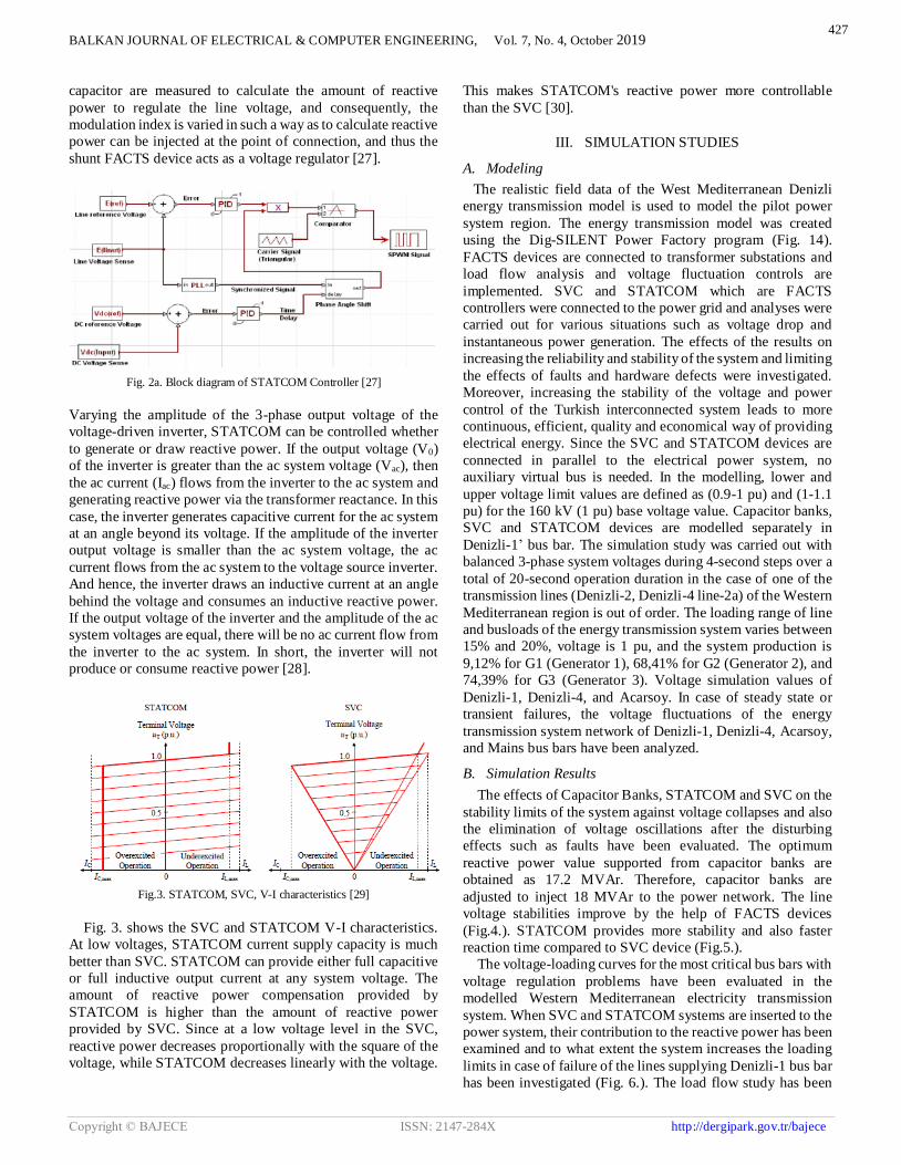
capacitor are measured to calculate the amount of reactive
power to regulate the line voltage, and consequently, the
modulation index is varied in such a way as to calculate reactive
power can be injected at the point of connection, and thus the
shunt FACTS device acts as a voltage regulator [27].
Fig. 2a. Block diagram of STATCOM Controller [27]
Varying the amplitude of the 3-phase output voltage of the
voltage-driven inverter, STATCOM can be controlled whether
to generate or draw reactive power. If the output voltage (V0)
of the inverter is greater than the ac system voltage (Vac), then
the ac current (Iac) flows from the inverter to the ac system and
generating reactive power via the transformer reactance. In this
case, the inverter generates capacitive current for the ac system
at an angle beyond its voltage. If the amplitude of the inverter
output voltage is smaller than the ac system voltage, the ac
current flows from the ac system to the voltage source inverter.
And hence, the inverter draws an inductive current at an angle
behind the voltage and consumes an inductive reactive power.
If the output voltage of the inverter and the amplitude of the ac
system voltages are equal, there will be no ac current flow from
the inverter to the ac system. In short, the inverter will not
produce or consume reactive power [28].
Fig.3. STATCOM, SVC, V-I characteristics [29]
Fig. 3. shows the SVC and STATCOM V-I characteristics.
At low voltages, STATCOM current supply capacity is much
better than SVC. STATCOM can provide either full capacitive
or full inductive output current at any system voltage. The
amount of reactive power compensation provided by
STATCOM is higher than the amount of reactive power
provided by SVC. Since at a low voltage level in the SVC,
reactive power decreases proportionally with the square of the
voltage, while STATCOM decreases linearly with the voltage.
This makes STATCOM's reactive power more controllable
than the SVC [30].
III. SIMULATION STUDIES
A. Modeling
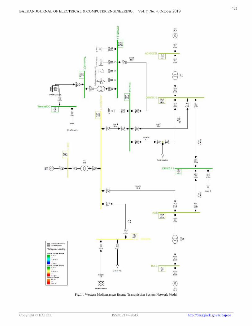
The realistic field data of the West Mediterranean Denizli
energy transmission model is used to model the pilot power
system region. The energy transmission model was created
using the Dig-SILENT Power Factory program (Fig. 14).
FACTS devices are connected to transformer substations and
load flow analysis and voltage fluctuation controls are
implemented. SVC and STATCOM which are FACTS
controllers were connected to the power grid and analyses were
carried out for various situations such as voltage drop and
instantaneous power generation. The effects of the results on
increasing the reliability and stability of the system and limiting
the effects of faults and hardware defects were investigated.
Moreover, increasing the stability of the voltage and power
control of the Turkish interconnected system leads to more
continuous, efficient, quality and economical way of providing
electrical energy. Since the SVC and STATCOM devices are
connected in parallel to the electrical power system, no
auxiliary virtual bus is needed. In the modelling, lower and
upper voltage limit values are defined as (0.9-1 pu) and (1-1.1
pu) for the 160 kV (1 pu) base voltage value. Capacitor banks,
SVC and STATCOM devices are modelled separately in
Denizli-1’ bus bar. The simulation study was carried out with
balanced 3-phase system voltages during 4-second steps over a
total of 20-second operation duration in the case of one of the
transmission lines (Denizli-2, Denizli-4 line-2a) of the Western
Mediterranean region is out of order. The loading range of line
and busloads of the energy transmission system varies between
15% and 20%, voltage is 1 pu, and the system production is
9,12% for G1 (Generator 1), 68,41% for G2 (Generator 2), and
74,39% for G3 (Generator 3). Voltage simulation values of
Denizli-1, Denizli-4, and Acarsoy. In case of steady state or
transient failures, the voltage fluctuations of the energy
transmission system network of Denizli-1, Denizli-4, Acarsoy,
and Mains bus bars have been analyzed.
B. Simulation Results
The effects of Capacitor Banks, STATCOM and SVC on the
stability limits of the system against voltage collapses and also
the elimination of voltage oscillations after the disturbing
effects such as faults have been evaluated. The optimum
reactive power value supported from capacitor banks are
obtained as 17.2 MVAr. Therefore, capacitor banks are
adjusted to inject 18 MVAr to the power network. The line
voltage stabilities improve by the help of FACTS devices
(Fig.4.). STATCOM provides more stability and also faster
reaction time compared to SVC device (Fig.5.).
The voltage-loading curves for the most critical bus bars with
voltage regulation problems have been evaluated in the
modelled Western Mediterranean electricity transmission
system. When SVC and STATCOM systems are inserted to the
power system, their contribution to the reactive power has been
examined and to what extent the system increases the loading
limits in case of failure of the lines supplying Denizli-1 bus bar
has been investigated (Fig. 6.). The load flow study has been
427
BALKAN JOURNAL OF ELECTRICAL & COMPUTER ENGINEERING, Vol. 7, No. 4, October 2019
Copyright © BAJECE ISSN: 2147-284X http://dergipark.gov.tr/bajece
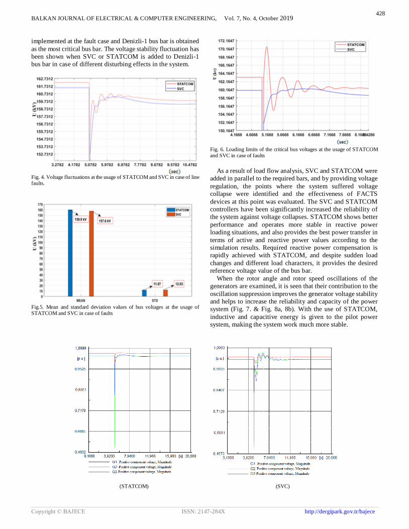
implemented at the fault case and Denizli-1 bus bar is obtained
as the most critical bus bar. The voltage stability fluctuation has
been shown when SVC or STATCOM is added to Denizli-1
bus bar in case of different disturbing effects in the system.
Fig. 4. Voltage fluctuations at the usage of STATCOM and SVC in case of line faults.
Fig.5. Mean and standard deviation values of bus voltages at the usage of STATCOM and SVC in case of faults
Fig. 6. Loading limits of the critical bus voltages at the usage of STATCOM and SVC in case of faults
As a result of load flow analysis, SVC and STATCOM were
added in parallel to the required bars, and by providing voltage
regulation, the points where the system suffered voltage
collapse were identified and the effectiveness of FACTS
devices at this point was evaluated. The SVC and STATCOM
controllers have been significantly increased the reliability of
the system against voltage collapses. STATCOM shows better
performance and operates more stable in reactive power
loading situations, and also provides the best power transfer in
terms of active and reactive power values according to the
simulation results. Required reactive power compensation is
rapidly achieved with STATCOM, and despite sudden load
changes and different load characters, it provides the desired
reference voltage value of the bus bar.
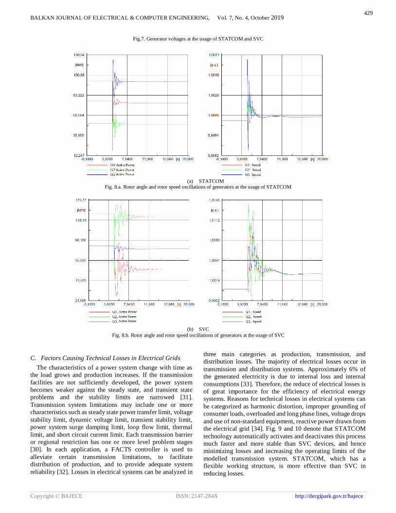
When the rotor angle and rotor speed oscillations of the
generators are examined, it is seen that their contribution to the
oscillation suppression improves the generator voltage stability
and helps to increase the reliability and capacity of the power
system (Fig. 7. & Fig. 8a, 8b). With the use of STATCOM,
inductive and capacitive energy is given to the pilot power
system, making the system work much more stable.
(STATCOM) (SVC)
428
BALKAN JOURNAL OF ELECTRICAL & COMPUTER ENGINEERING, Vol. 7, No. 4, October 2019
Copyright © BAJECE ISSN: 2147-284X http://dergipark.gov.tr/bajece
Fig.7. Generator voltages at the usage of STATCOM and SVC
(a) STATCOM
Fig. 8.a. Rotor angle and rotor speed oscillations of generators at the usage of STATCOM
(b) SVC
Fig. 8.b. Rotor angle and rotor speed oscillations of generators at the usage of SVC
C. Factors Causing Technical Losses in Electrical Grids
The characteristics of a power system change with time as
the load grows and production increases. If the transmission
facilities are not sufficiently developed, the power system
becomes weaker against the steady state, and transient state
problems and the stability limits are narrowed [31].
Transmission system limitations may include one or more
characteristics such as steady state power transfer limit, voltage
stability limit, dynamic voltage limit, transient stability limit,
power system surge damping limit, loop flow limit, thermal
limit, and short circuit current limit. Each transmission barrier
or regional restriction has one or more level problem stages
[30]. In each application, a FACTS controller is used to
alleviate certain transmission limitations, to facilitate
distribution of production, and to provide adequate system
reliability [32]. Losses in electrical systems can be analyzed in
three main categories as production, transmission, and
distribution losses. The majority of electrical losses occur in
transmission and distribution systems. Approximately 6% of
the generated electricity is due to internal loss and internal
consumptions [33]. Therefore, the reduce of electrical losses is
of great importance for the efficiency of electrical energy
systems. Reasons for technical losses in electrical systems can
be categorized as harmonic distortion, improper grounding of
consumer loads, overloaded and long phase lines, voltage drops
and use of non-standard equipment, reactive power drawn from
the electrical grid [34]. Fig. 9 and 10 denote that STATCOM
technology automatically activates and deactivates this process
much faster and more stable than SVC devices, and hence
minimizing losses and increasing the operating limits of the
modelled transmission system. STATCOM, which has a
flexible working structure, is more effective than SVC in
reducing losses.
429

BALKAN JOURNAL OF ELECTRICAL & COMPUTER ENGINEERING, Vol. 7, No. 4, October 2019
Copyright © BAJECE ISSN: 2147-284X http://dergipark.gov.tr/bajece
The effects of active and reactive power flow and the critical
power system parameters such as total transmission losses on
the transmission line are investigated when FACTS devices are
inserted. In the usage of SVC and STATCOM, the differences
of consumed and generated average active power were 0.9361
and 0.645 MW/h respectively (Fig.9. & 10.). STATCOM
provides 31.09 % more achievement with respect to SVC
device, and this corresponds to 0.2911 MW/h less generation
and consumption loss.
Fig.9. Energy production and consumptions at the usage of STATCOM
Fig.10. Energy production and consumptions at the usage of SVC
Fig.11. Generator Reactive Power Generations (STATCOM) Before/After Line Faults
Fig.12. Generator Reactive Power Generation (SVC) Before/After Line Faults
Fig.13. Generator Reactive Power Generation (Capacitor) Before/After Line Faults
In the simulation study, line faults resulted in critical
increases in generator loadings. Reactive power loadings may
be reduced by the usage of capacitor banks, SVC, and
STATCOM. The total reactive power generation of three
generators after the faults are 24.139, 22.249, and 19.389
MVAr for capacitor banks, SVC and STATCOM, respectively.
The results depict that the lowest reactive power necessity of
the power network before/after the line faults occurs when
STATCOM device is used (Fig. 11., 12. & 13.).
The comparison of reactive compensation devices such as
capacitor banks, SVC and STATCOM on active and reactive
power loadings and reactive power losses are shown by Table
I. Active power loadings, capacitive reactive loadings, and
reactive power losses of the transmission lines have been
reduced by SVC/STATCOM devices 0.24%, 0.55%, 1%
respectively. SVC and STATCOM devices decrease the
loadings and also reactive power losses more than capacitor
banks. Considering the all Turkish electrical power system,
these reductions in losses are going to constitute a very
substantial economic benefit. Voltage stability of the grid was
provided as a result of STATCOM and SVC use of the power
system model of the Western Mediterranean region electricity
power transmission system of the Denizli region. Fluctuations
of voltage stability in case of system overload or failure have
been analyzed. Voltage and power stability values of the lines,
and voltage values of load bus bars have been obtained for the
generated power system model. Bus bar voltages are shown by
430

BALKAN JOURNAL OF ELECTRICAL & COMPUTER ENGINEERING, Vol. 7, No. 4, October 2019
Copyright © BAJECE ISSN: 2147-284X http://dergipark.gov.tr/bajece
using Capacitor, SVC, and STATCOM devices before and after
faults (Tables II and III). As can be seen from the results, the
STATCOM device regulates the voltage much better than SVC
and capacitor banks. Bus bar voltages are hardly affected by the
fault thanks to the use of STATCOM (Table III).
TABLE I
TRANSMISSION LINE STATUS (AT THE USAGE OF FACTS DEVICES) AFTER LINE FAULTS
Lines
ACTIVE POWER LOADING (%) CAPACITIVE REACTIVE
LOADING (MVAr)
REACTIVE POWER LOSS
(MVAr)
CAPACITOR ENABLED
SVC / STATCOM ENABLED
CAPACITOR ENABLED
SVC / STATCOM ENABLED
CAPACITOR ENABLED
SVC / STATCOM ENABLED
Line 7.99699 7.99706 11.01927 10.99988 -10.17619 -10.15604
Line (1) 1.91172 1.91000 11.10064 11.08061 -11.10064 -11.08061
Line (2) 15.43685 15.4004 7.91846 7.87871 -4.49485 -4.45075
Line 1 30.22983 30.36543 8.97983 8.93827 3.32629 3.45375
Line 2a 9.30884 9.22839 1.54765 1.54355 -1.33054 -1.32984
Line 2b 9.13218 9.06786 13.81726 13.74428 -12.07093 -11.99212
Line 3 11.42976 11.36274 7.30717 7.29224 -6.06996 -6.06952
Line 4 25.05796 25.10335 10.30962 10.29939 -0.41096 -0.37028
Line 5 12.48466 12.4395 18.51381 18.49452 -15.12844 -15.12671
Line 6 19.07388 18.85184 15.77896 15.44046 -5.70820 -5.39699
TABLE II BUS VOLTAGES WHEN FACTS DEVICES OPERATES
(THERE IS NO FAULT)
Bus ID CAPACITOR
ENABLED SVC
ENABLED STATCOM ENABLED
DENİZLİ-1 (kV)
(pu)
161.9342 1.01208
160.0 1.0
160.0 1.0
DENİZLİ-2 (kV)
(pu)
163.2398 1.02024
163.1085 1.01942
163.1085 1.01942
DENİZLİ-3 (kV)
(pu)
158.4197 0.99012
158.3302 0.98956
158.3302 0.98956
DENİZLİ-4 (kV)
(pu)
161.4339 1.008961
161.0137 1.00633
161.0137 1.00633
ACARSOY (kV)
(pu)
165.177 1.03235
165.08 1.03175
165.08 1.03175
NETWORK (kV)
(pu)
160.8582 1.005361
160.7506 1.00469
160.7506 1.00469
TABLE III
BUS VOLTAGES WHEN FACTS DEVICES OPERATES (AFTER LINE FAULT OCCURS)
Bus ID CAPACITOR
ENABLED SVC
ENABLED STATCOM ENABLED
DENİZLİ-1 (kV)
(pu)
157.8052 0.98628
160.0 1.0
160.0 1.0
DENİZLİ-2 (kV)
(pu)
162.1797 1.01362
162.3029 1.01439
162.3029 1.01439
DENİZLİ-3 (kV) (pu)
157.8219 0.98638
157.9073 0.98692
157.9073 0.98692
DENİZLİ-4 (kV)
(pu)
158.2907 0.98931
158.8408 0.99275
158.8408 0.99275
ACARSOY (kV)
(pu)
164.3486 1.02717
164.4754 1.02797
164.4754 1.02797
NETWORK (kV)
(pu)
159.9385 0.99961
160.0793 1.00049
160.0793 1.00049
IV. CONCLUSION
Implementing voltage and reactive power control by
SVC/STATCOM controller in the power system, technical
losses can be reduced, and electrical energy can be transmitted
in a stable, controlled, and most economical way. Results denote
that the sensitivity of voltage and reactive power control are
improved and the production and consumption balance become
more stable by the usage of FACTS devices. When the modeled
pilot region is evaluated in terms of oscillatory operation and
voltage drop, FACTS devices can increase the maximum load
point of the system against voltage collapse more than the
continually operated capacitor banks. In case of failure of one
of the lines in the network, it has been determined that FACTS
devices can suppress oscillatory operation mode, which occurs
at bus voltage, generator rotor speeds, and rotor angles. Results
show that STATCOM and SVC systems increase the maximum
load and limits, improve the stability limits in the case of a
disturbing effect on the power system, and prevent the voltage
collapse under overload conditions. The reactive power losses
and correspondingly the electricity costs may be reduced by 1
% by SVC/STATCOM devices. STATCOM controllers have
% 31.09 higher performance compared to SVC at assuring the
energy production and consumption balance.
ACKNOWLEDGMENT
This study has been supported by Akdeniz University Scientific
Research Projects Coordination Department within the scope of
the project no: FBA-2018-3792 for the possibility to complete a
scientific research.
REFERENCES
[1] Kalair A, Abas N, Kalair AR, Saleem Z, Khan N. “Review of harmonic analysis, modeling and mitigation techniques. Renew Sustain Energy” Rev 2017, 78 (10), pp. 1152–1187.
[2] Martínez EB, Camacho CÁ. “Technical comparison of FACTS controllers in parallel connection” J Appl Res Technol 2017, 15(1), pp.36–44.
[3] Jumaat SA, Musirin I, Baharun MM. “A voltage improvement of transmission system using static var compensator via matlab/Simulink” Indones J Electr Eng Comput Sci 2017, 6(2), pp. 1–17.
[4] Fadaee M, Radzi MAM. “Multi-objective optimization of a stand-alone hybrid renewable energy system by using evolutionary algorithms: a review. Renew Sustain Energy” Rev 2012, 16(5), pp. 3364-2269.
[5] Sadaiappan S, Renuga P, Kavitha D. “Modeling and simulation of series compensator to mitigate power quality problems” Int J Eng Sci Technol 2010, 2(12), pp. 7385–7394.
431
BALKAN JOURNAL OF ELECTRICAL & COMPUTER ENGINEERING, Vol. 7, No. 4, October 2019
Copyright © BAJECE ISSN: 2147-284X http://dergipark.gov.tr/bajece
[6] Liu L, Li H, Xue Y, Liu W. “Reactive power compensation and optimization strategy for grid-interactive cascaded photovoltaic systems” IEEE Trans Power Electron 2015, 30(1), pp. 188–202.
[7] Darabian M, Jalilvand A. “A power control strategy to improve power system stability in the presence of wind farms using FACTS devices and predictive control” Int J Electr Power Energy Syst 2017, 85(2), pp. 50–66.
[8] Sharaf AM, Gandoman FH. “A switched hybrid filter - DVS/green plug for smart grid nonlinear loads, in Smart Energy Grid Engineering” (SEGE), IEEE International Conference on; 17–19 Aug. 2015, pp. 1–6.
[9] Sharaf AM, Khaki B. Novel “switched capacitor-filter compensator for smart gridelectric vehicle charging scheme” in Proc. IEEE SGE, Oshawa, Canada; Aug 2012, pp.1–6.
[10] Abdelsalam AA, Desouki ME, Sharaf AM. “Power quality improvement using FACTS power filter compensation scheme” J Electr Syst 2013, 9(1), pp.86–96.
[11] Mahela OP, Shaik AG, Gupta N. “A critical review of detection and classification of power quality events” Renew Sustain Energy Rev 2015, 41, pp.495–505.
[12] Velamuri S, Sreejith S. “Power flow analysis incorporating renewable energy sources and FACTS devices” Int J Renew Energy Res 2017, 7(1), pp.452–458.
[13] Crow ML. “Power quality enhancement using custom power devices” IEEE Power Energy Mag 2004, pp.2-50.
[14] Hingorani N. G. “Flexible AC Transmission” IEEE reprinted from IEEE Spectrum, Vol. 30, No.4, 1993, pp. 40-45.
[15] Cheng, H. In, I. and Chen S. “DC-Link Voltage Control and Performance Analysis of STATCOM”, 2002.
[16] Yang, Z. Shen, C. Zhang, L. Crow M. L.” Integration of a STATCOM and Battery Energy Storage”, IEEE Trans. on Power System, Vol. 16, no. 2, May 2001, pp. 254-260.
[17] Çöteli, “STATCOM ile Güç Akış Kontrolü”, Yüksek Lisans Tezi Elektrik Eğitimi, Fırat Üniversitesi Fen Bilimleri Enstitüsü Elazığ, 2006.
[18] Jaime Cepeda, Esteban Agüero, “FACTS models for stability studies in DIgSILENT Power Factory” IEEE Transmission and Distribution Latin America, 2014; DOI: 10.1109/TDC-LA.2014.6955182.
[19] T. Sriyawong, P. Sriyanyong, P. Koseeyaporn and P. Kongsakorn “A Modified Fast Decoupled Power Flow Algorithm” International Energy Journal: Vol. 6, No.1, Part 2, June 2005, pp. 2-95.
[20] H. Feza Carlak, E Kayar, “TCR-TSC SVC Sistemler Kullanılarak Enerji İletim Sistemlerinde Gerilim Regülasyonu Analizi”, 4th International Mediterranean Science and Engineering Congress IMSEC Alanya, 2019, pp. 476-481.
[21] Hingorani, Ng. Gyugyı, L. “Understanding FACTS: concepts and technology of flexible AC transmission systems” IEEE Press, New York, 2000.
[22] U. Arifoğlu, “Güç Sistemlerinin Bilgisayar Destekli Analizi”, Alfa Yayınları, İstanbul, 2002.
[23] C.A. Canizares, T.F. Zeno, “Analysis of SVC and TCSC Controllers in Voltage Collapse”, IEEE Transactions on Power Systems, Vol. 14, No. 1, February 1999.
[24] R. Kowalak, "Resonant Conditions in a Node with an SVC Compensator," Acta Energetica, vol. 3, no.28, July 2016, pp. 70-75.
[25] Schauder, C. and Mehta, H. “Vector Analysis and Control of Advanced Static VAR Compensators”, IEE Proceedings-C, Vol. 140, No.4, 1993, pp.299–306.
[26] S.M.Abd-Elazim, E.S.Ali, “Imperialist competitive algorithm for optimal STATCOM design in a multimachine power ” International Journal of Electrical Power & Energy Systems Vol. 76, March 2016, pp. 136-146.
[27] Md. Nazrul Islam, Md. Arifur Kabi1, and Yashiro Kazushige “Design and Simulation of STATCOM to Improve Power Quality” International
Journal of Innovation and Applied Studies ISSN 2028-9324 Vol. 3, No.3, July 2013, pp. 871-878.
[28] Gyugyi, L. “Power Electronics in Electric Utilities: Static Var Compensators”, Proceedings of The IEEE, vol. 76, no. 4, 1988, pp. 483-493.
[29] Y. H. Song et al., Flexible AC Transmission Systems (FACTS), London: IEEE, 1999.
[30] Paserba J. “How FACTS Controllers Benefit AC Transmission System” Trans. And Dist. Con. and Exp., IEEE PES Volume 3, 7-12 Sept. vol.3 2003, pp. 949 – 956.
[31] Acha E., Fuerte-Esquivel C., Ambriz-Pe´rez R., Angeles-Camacho H.,C., “FACTS Modelling and Simulation in Power Networks”, John Wiley & Sons LTD, 2004.
[32] Habur, K. D. O'Leary, “FACTS-Flexible Alternating Current Transmission Systems-For Cost Effective and Reliable Transmission of Electrical Energy”, 2000.
[33] Celal Yaşar, Yılmaz Aslan, Tarık Biçer, “Bir Dağıtım Tranformatörü Bölgesindeki Kayıpların İncelenmesi’’, Dumlupınar Üniversitesi, Fen Bilimleri Enstitüsü Dergisi, Sayı 22, Ağustos 2010.
[34] J.P Navani, N.K Sharma, Sonal Sapra, “Technical and Non-Technical Losses in Power System and Its Economic Consequence in Indian Economy’’, International Journal of Electronics and Computer Science Engineering, ISSN: 2277-1956, 2012.
BIOGRAPHIES
HAMZA FEZA CARLAK received the B.S.
degree in electrical engineering from the
Istanbul Technical University, Istanbul, in
2000 and the integrated Ph.D. degree in
electrical and electronics engineering from
Middle East Technical University,
Ankara, in 2012.
From 2003 to 2013, he was a Research
Assistant in the Middle East Technical University. Since 2017,
he has been an Assistant Professor with the Electrical and
Electronics Engineering Department, Akdeniz University. He is
the author of more than 30 articles, and has an invention on the
medical imaging modality. His research interests include power
systems, medical imaging, thermal imaging, image processing,
renewable energy and artificial neural network algorithms.
ERGİN KAYAR received the B.S. degree in
electrical and electronics engineering from
the Akdeniz University, Antalya, in 2017
and he has been doing a master's degree at
Akdeniz University, Department of
Electrical and Electronics Engineering. He
has been working in Turkey Electrical
Communication Corporation (TEIAS) as
an electrical engineer for 8 years. His
research interests include power systems, renewable energy and
energy transmission systems.
432
BALKAN JOURNAL OF ELECTRICAL & COMPUTER ENGINEERING, Vol. 7, No. 4, October 2019
Copyright © BAJECE ISSN: 2147-284X http://dergipark.gov.tr/bajece
Fig.14. Western Mediterranean Energy Transmission System Network Model
433