voip call admission control - cisco - global home …...voip call admission control call admission...
TRANSCRIPT

VoIP Call Admission Control
Call Admission Control (CAC) is a concept that applies to voice traffic only—not data traffic. If an influx of data traffic oversubscribes a particular link in the network, queueing, buffering, and packet drop decisions resolve the congestion. The extra traffic is simply delayed until the interface becomes available to send the traffic, or, if traffic is dropped, the protocol or the end user initiates a timeout and requests a retransmission of the information.
Network congestion cannot be resolved in this manner when real-time traffic, sensitive to both latency and packet loss, is present, without jeopardizing the quality of service (QoS) expected by the users of that traffic. For real-time delay-sensitive traffic such as voice, it is better to deny network access under congestion conditions than to allow traffic onto the network to be dropped and delayed, causing intermittent impaired QoS and resulting in customer dissatisfaction.
CAC is therefore a deterministic and informed decision that is made before a voice call is established and is based on whether the required network resources are available to provide suitable QoS for the new call. The purpose of this document is to provide an overview of CAC, describe the different CAC mechanisms, and discuss how to best apply CAC to specific networks.
The targeted audience for this document is Cisco level 3 (competent), level 4 (proficient), and level 5 (expert) users. This document is intended primarily for network administrators and operations teams working for service providers that provide VoIP services. This document contains the following sections:
• Call Admission Control Overview, page 2
• Local CAC Mechanisms, page 9
• Measurement Based CAC Mechanisms, page 18
• Resource-Based CAC Mechanisms, page 26
• How to Apply CAC to Your Network, page 45
Version Number Date Notes
1.1 July 2001 This document was first published.
1.2 Aug. 2001 Minor changes.
1

VoIP Call Admission ControlCall Admission Control Overview
Call Admission Control OverviewA variety of QoS mechanisms other than CAC exist in Cisco IOS software for the purpose of designing and configuring packet networks to provide the necessary low latency and guaranteed delivery required for voice traffic. These QoS mechanisms include tools such as queueing, policing, traffic shaping, packet marking, and fragmentation and interleaving. These mechanisms differ from CAC in the following important ways:
• They are designed to protect voice traffic from data traffic contending for the same network resources.
• They are designed to deal with traffic already present on the network.
CAC mechanisms extend the capabilities of the QoS tool suite to protect voice traffic from being negatively affected by other voice traffic, and to keep excess voice traffic off the network. Figure 1 shows why CAC is needed. If the WAN access link between the two PBXs has the bandwidth to carry only two VoIP calls, admitting the third call will impair the voice quality of all three calls.
Figure 1 VoIP Network Without CAC
The reason for this impairment is that the queueing mechanisms provide policing, not CAC, which means that if packets exceeding the configured or allowable rate are received, these packets are simply tail-dropped from the queue. There is no capability in the queueing mechanisms to distinguish which IP packet belongs to which voice call, so any packet exceeding the given arrival rate within a certain period of time will be dropped. Thus, all three calls will experience packet loss, which is perceived as clips by the end users.
This problem is easier to solve for the Layer 2 voice transport mechanisms (VoFR and VoATM), but is particularly vexing for the predominant and far more attractive VoIP applications.
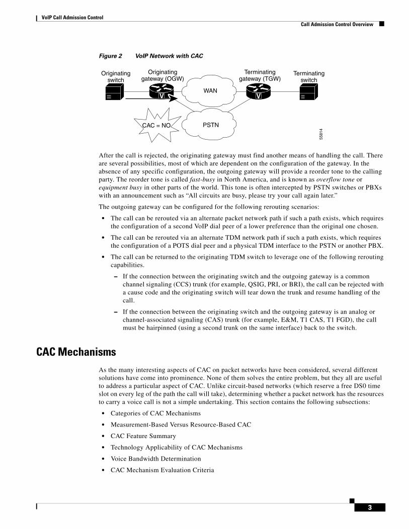
Call Rerouting AlternativesFigure 2 illustrates the point at which a CAC decision is reached by the outgoing gateway that insufficient network resources are available to allow a call to proceed.
V V
x1111
x1112
x1113
x1111
x1112
x1113
PBX PBX
VOIP DataNetwork
Call #2
Call #3
Call #1
Call #3 causes poor quality for all calls 5581
3
2
VoIP Call Admission ControlCall Admission Control Overview
Figure 2 VoIP Network with CAC
After the call is rejected, the originating gateway must find another means of handling the call. There are several possibilities, most of which are dependent on the configuration of the gateway. In the absence of any specific configuration, the outgoing gateway will provide a reorder tone to the calling party. The reorder tone is called fast-busy in North America, and is known as overflow tone or equipment busy in other parts of the world. This tone is often intercepted by PSTN switches or PBXs with an announcement such as “All circuits are busy, please try your call again later.”
The outgoing gateway can be configured for the following rerouting scenarios:
• The call can be rerouted via an alternate packet network path if such a path exists, which requires the configuration of a second VoIP dial peer of a lower preference than the original one chosen.
• The call can be rerouted via an alternate TDM network path if such a path exists, which requires the configuration of a POTS dial peer and a physical TDM interface to the PSTN or another PBX.
• The call can be returned to the originating TDM switch to leverage one of the following rerouting capabilities.
– If the connection between the originating switch and the outgoing gateway is a common channel signaling (CCS) trunk (for example, QSIG, PRI, or BRI), the call can be rejected with a cause code and the originating switch will tear down the trunk and resume handling of the call.
– If the connection between the originating switch and the outgoing gateway is an analog or channel-associated signaling (CAS) trunk (for example, E&M, T1 CAS, T1 FGD), the call must be hairpinned (using a second trunk on the same interface) back to the switch.
CAC MechanismsAs the many interesting aspects of CAC on packet networks have been considered, several different solutions have come into prominence. None of them solves the entire problem, but they all are useful to address a particular aspect of CAC. Unlike circuit-based networks (which reserve a free DS0 time slot on every leg of the path the call will take), determining whether a packet network has the resources to carry a voice call is not a simple undertaking. This section contains the following subsections:
• Categories of CAC Mechanisms
• Measurement-Based Versus Resource-Based CAC
• CAC Feature Summary
• Technology Applicability of CAC Mechanisms
• Voice Bandwidth Determination
• CAC Mechanism Evaluation Criteria
V VWAN
Originatingswitch
Terminatingswitch
Terminatinggateway (TGW)
Originatinggateway (OGW)
5581
4
PSTNCAC = NO
3
VoIP Call Admission ControlCall Admission Control Overview
Categories of CAC Mechanisms
The remainder of this document discusses ten different CAC mechanisms available in current versions of Cisco IOS software. They are grouped into the following three categories:
• Local CAC Mechanisms—Local CAC mechanisms function on the outgoing gateway. The CAC decision is based on nodal information such as the state of the outgoing LAN or WAN link. If the local packet network link is down, there is no point in executing complex decision logic based on the state of the rest of the network, because that network is unreachable. Local mechanisms include configuration items to disallow more than a fixed number of calls. For example, if the network designer already knows that no more than five calls can fit across the outgoing WAN link because of bandwidth limitations, then it seems logical that it should be possible to configure the local node to allow no more than five calls.
• Measurement Based CAC Mechanisms—Measurement-based CAC techniques look ahead into the packet network to gauge the state of the network in order to determine whether to allow a new call. Gauging the state of the network implies sending probes to the destination IP address (usually the terminating gateway or terminating gatekeeper) that will return to the outgoing gateway with some measured information on the conditions the probe found while traversing the network to the destination. Typically, loss and delay characteristics are the interesting information elements for voice.
• Resource-Based CAC Mechanisms—There are two types of resource-based mechanisms: those that calculate resources needed and/or available, and those reserving resources for the call. Resources of interest include link bandwidth, DSPs and DS0 time slots on the connecting TDM trunks, CPU power, and memory. Several of these resources could be constrained at any one or more of the nodes the call will traverse to its destination.
There are two additional categories of CAC functionality, but they do not address network design or infrastructure issues and therefore are not discussed in this document. These two CAC categories—security and user—focus instead on the policy question of whether the call or the end user is allowed to use the network, as follows:
• Security—Is this a legitimate device or gateway on the network? There are authentication mechanisms, including protocols such as H.235, to cover this aspect of CAC.
• User—Is this end user authorized to use the network? There are CLID/ANI and PIN verification methods, typically done via interactive voice response (IVR), to verify authorization.
Measurement-Based Versus Resource-Based CAC
There is little overlap between local CAC mechanisms and those that look ahead to the rest of the network to determine nonlocal conditions. It is thus easy to understand why distinct local and “cloud” mechanisms are useful. However, there is considerable overlap between the measurement techniques and the resource reservation techniques of the two “cloud look-ahead” CAC mechanisms. For this reason there is debate over which is the better method.
Table 1 compares the strengths and weaknesses of the measurement-based and resource-based CAC mechanisms. With this information, you can determine the best method for your individual network.
4
VoIP Call Admission ControlCall Admission Control Overview
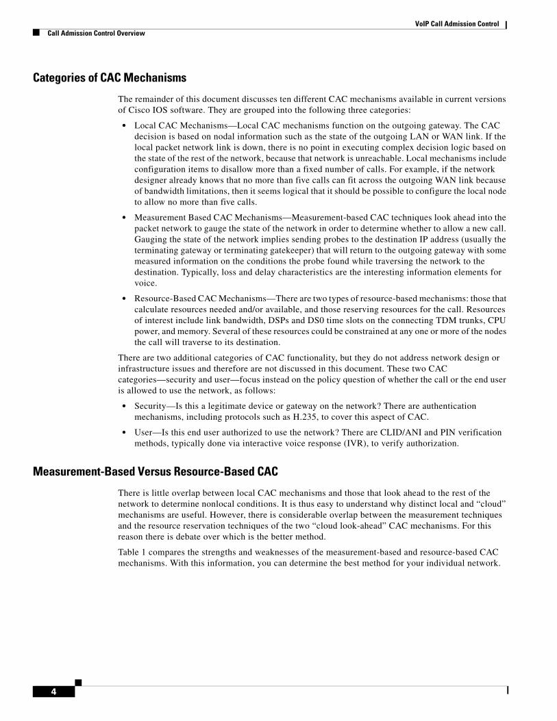
Table 1 Comparison of Measurement-Based and Resource Reservation-Based CAC Features
Criteria Measurement-Based Techniques Resource Reservation-Based Techniques
Network topology Topology-independent.
The probe travels to a destination IP address—it has no knowledge of nodes, hops, and bandwidth availability on individual links.
Topology aware.
The bandwidth availability on every node and every link is taken into account.
Backbone transparency Transparent.
Probes are IP packets and can be sent over any network, including SP backbones and the Internet.
To be the truly end-to-end method that reservation techniques are intended to be, the feature must be configured on every interface along the path, which means the customer owns the WAN backbone, and all nodes run code that implement the feature. Owning the entire backbone is impractical in some cases, so hybrid topologies may be contemplated—with some compromise to the end-to-end nature of the method.
Postdial delay An increase in postdial delay exists for the first call only; information on the destination is cached after that, and a periodic probe is sent to the IP destination. Subsequent calls are allowed or denied based on the latest cached information.
An increase in postdial delay exists for every call, as the Resource Reservation Protocol (RSVP) reservation must be established before the call setup can be completed.
Industry parity Several vendors have “ping”-like CAC capabilities. For a customer familiar with this operation, measurement-based techniques are a good fit.
—
CAC accuracy The periodic sampling rate of probes can potentially admit calls when bandwidth is insufficient. Measurement-based techniques perform well in networks where traffic fluctuations are gradual.
When implemented on all nodes in the path, RSVP guarantees bandwidth for the call along the entire path for the entire duration of the call. This is the only technique that achieves this level of accuracy.
Protecting voice QoS after admission
The CAC decision is based on probe traffic statistics before the call is admitted. After admission, the call quality is determined by the effectiveness of other QoS mechanisms in the network.
A reservation is established per call before the call is admitted. The quality of the call is therefore unaffected by changes in network traffic conditions.
5
VoIP Call Admission ControlCall Admission Control Overview
CAC Feature Summary
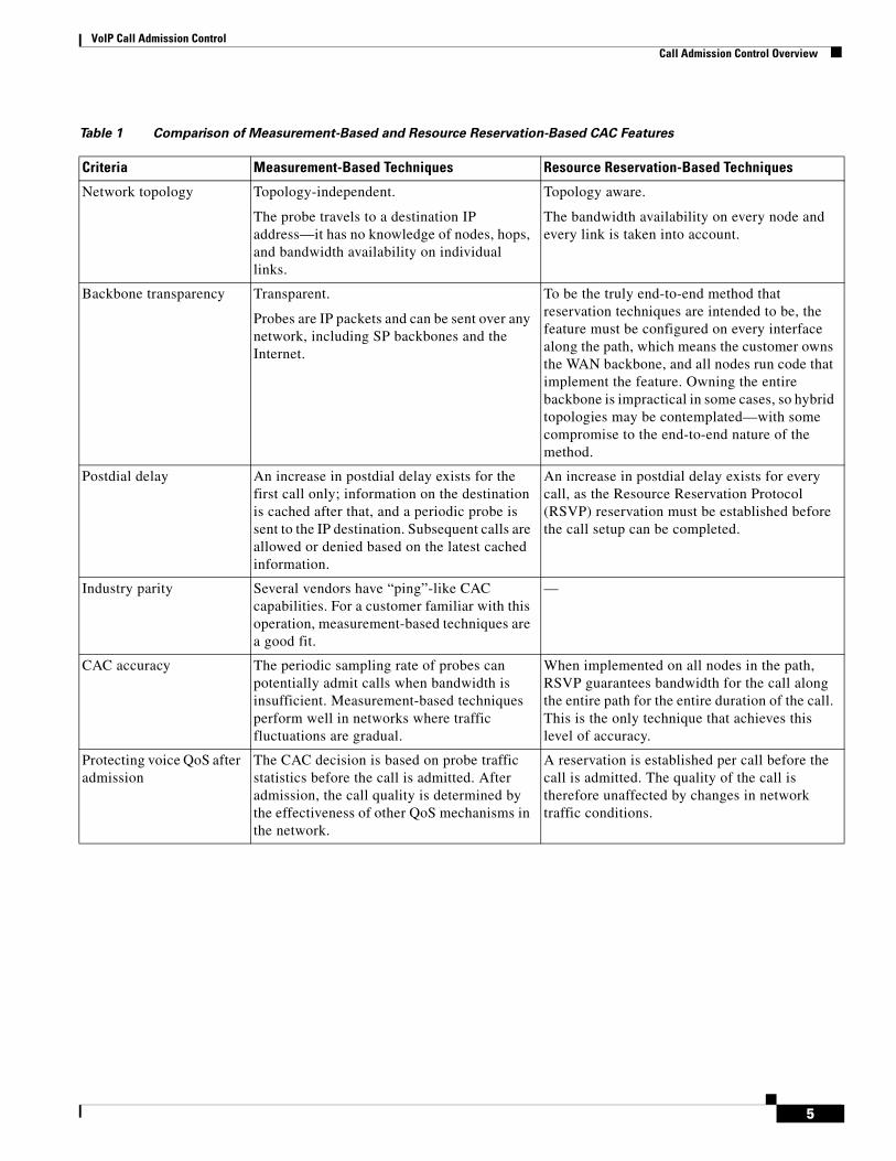
Table 2 summarizes the ten different voice CAC mechanisms that will be discussed in detail in this document. It also lists the first Cisco IOS release in which the feature became available.
Network traffic overhead Periodic probe traffic overhead to a cached number of IP destinations. Both the interval and the cache size can be controlled by the configuration.
RSVP messaging traffic overhead for every call.
Scalability Sending probes to thousands of individual IP destinations may be impractical in a large network. However, probes can be sent to the WAN edge devices, which proxy on behalf of many more destinations on a high-bandwidth campus network behind the edge. This provides considerable scalability, because the WAN is much more likely to be congested than the campus LAN.
Individual flow reservation is important on the small-bandwidth links around the edge of the network. However, individual reservations per call flow may not make sense on large-bandwidth links in the backbone such as an OC-12. Hybrid network topologies can solve this need, and additional upcoming RSVP tools in this space will provide further scalability.
Table 1 Comparison of Measurement-Based and Resource Reservation-Based CAC Features
Criteria Measurement-Based Techniques Resource Reservation-Based Techniques
Table 2 CAC Features
Type CAC Feature SW Release
Local
Physical DS0 Limitation SW independent
Max-Connections on the dial peer 11.3
VoFR Voice Bandwidth 12.0.(4)T
Trunk Conditioning 12.1.(2)T
Local Voice Busyout (LVBO) 12.1.(2)T
Measurement-based
Advanced Voice Busyout (AVBO) 12.1.(3)T
PSTN Fallback 12.1.(3)T
Resource-based
• Resource Calculation
Resource Availability Indication 12.0.(5)T (AS5300)12.1.(3)T (2600/3600)
Gatekeeper Zone Bandwidth 11.(3) (local zone)12.1.(5)T (interzone)
• Resource Reservation
Resource Reservation Protocol 12.1.(5)T
6
VoIP Call Admission ControlCall Admission Control Overview
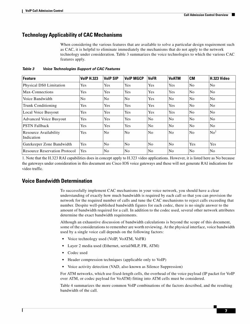
Technology Applicability of CAC Mechanisms
When considering the various features that are available to solve a particular design requirement such as CAC, it is helpful to eliminate immediately the mechanisms that do not apply to the network technology under consideration. Table 3 summarizes the voice technologies to which the various CAC features apply.
Voice Bandwidth Determination
To successfully implement CAC mechanisms in your voice network, you should have a clear understanding of exactly how much bandwidth is required by each call so that you can provision the network for the required number of calls and tune the CAC mechanisms to reject calls exceeding that number. Despite well-published bandwidth figures for each codec, there is no single answer to the amount of bandwidth required for a call. In addition to the codec used, several other network attributes determine the exact bandwidth requirements.
Although an exhaustive discussion of bandwidth calculations is beyond the scope of this document, some of the considerations to remember are worth reviewing. At the physical interface, voice bandwidth used by a single voice call depends on the following factors:
• Voice technology used (VoIP, VoATM, VoFR)
• Layer 2 media used (Ethernet, serial/MLP, FR, ATM)
• Codec used
• Header compression techniques (applicable only to VoIP)
• Voice activity detection (VAD, also known as Silence Suppression)
For ATM networks, which use fixed-length cells, the overhead of the voice payload (IP packet for VoIP over ATM, or codec payload for VoATM) fitting into ATM cells must be considered.
Table 4 summarizes the more common VoIP combinations of the factors described, and the resulting bandwidth of the call.
Table 3 Voice Technologies Support of CAC Features
Feature VoIP H.323 VoIP SIP VoIP MGCP VoFR VoATM CM H.323 Video
Physical DS0 Limitation Yes Yes Yes Yes Yes No No
Max-Connections Yes Yes Yes Yes Yes No No
Voice Bandwidth No No No Yes No No No
Trunk Conditioning Yes Yes Yes Yes Yes No No
Local Voice Busyout Yes Yes Yes Yes Yes No No
Advanced Voice Busyout Yes Yes Yes No No No No
PSTN Fallback Yes Yes Yes No No No No
Resource Availability Indication
Yes No No No No No No1
1. Note that the H.323 RAI capabilities does in concept apply to H.323 video applications. However, it is listed here as No because the gateways under consideration in this document are Cisco IOS voice gateways and these will not generate RAI indications for video traffic.
Gatekeeper Zone Bandwidth Yes No No No No Yes Yes
Resource Reservation Protocol Yes No No No No No No
7

VoIP Call Admission ControlCall Admission Control Overview
The formula used to calculate the bandwidth for any other combination of factors is:
Voice bandwidth = (Payload + L3 + L2) * 8 * pps
The elements in the formula correspond to the following values:
• Payload = Payload in bytes generated by the codec
• L3 = Layer 3 and higher layer header overhead in bytes (0 for VoFR and VoATM)
• L2 = Link Layer header overhead in bytes
• 8 = Number of bits per byte
• pps= Packets per second rate generated by the codec
The Layer 2 transport technologies have the following header overheads:
• Ethernet: 14 bytes
• PPP and MLP: 6 bytes
• FrameRelay: 6 bytes
• ATM (AAL5): 5 bytes (plus cell fill waste)
• MLP over FrameRelay: 14 bytes
• MLP over ATM (AAL5): 5 bytes for every ATM cell + 20 bytes for the MLP and AAL5 encapsulation of the IP packet
The following are examples of bandwidth calculations:
• G.729 / VoIP / MLPPP / no cRTP / no VAD: (20 + 40 + 6) * 8 * 50 = 26.4 kbps
• G.729 / MLPPP / cRTP / no VAD: (20 + 2 + 6) * 8 * 50 = 11.2 kbps
• G.729 / VoIPovFR / no cRTP / no VAD: (20 + 40 + 6) * 8 * 50 = 26.4 kbps
• G.729 / VoFR / no VAD: (20 + 6) * 8 * 50 = 10.4 kbps
CAC Mechanism Evaluation Criteria
As each CAC method is described in the remainder of this document, it will be evaluated against various factors and criteria that will help determine which is the best or most appropriate CAC mechanism for the network design under consideration.
Table 5 describes the criteria that will be used to evaluate the different CAC tools.
Table 4 VoIP Bandwidth Requirements
Codec
Codec Bandwidth (kbps)
Sample Length (ms)
Sample Size (Bytes)
Samples per Packet
IP Header Size (Bytes)
Layer 2 Technology
Layer 2 Header Size (Bytes)
Voice Call Bandwidth Required (kbps)
G.711 64 10 80 2 40 Ethernet 14 85.6
G.711 64 10 80 2 40 MLP/FR 6 82.4
G.711 64 10 80 2 2 (cRTP) MLP/FR 6 67.2
G.729 8 10 10 2 40 Ethernet 14 29.6
G.729 8 10 10 2 40 MLP/FR 6 26.4
G.729 8 10 10 2 2 (cRTP) MLP/FR 6 11.2
8

VoIP Call Admission ControlLocal CAC Mechanisms
Local CAC MechanismsThe local mechanisms are the simplest CAC mechanisms to understand and implement. They work on the outgoing gateway and consider the local conditions of the node. They also tend to have low overhead, so if any of these mechanisms provide the desired functionality, there is little reason to implement any of the more complex features. However, it is likely that in a network of any reasonable size, satisfactory CAC functionality will require more than the use of a local mechanism.
In this section the following five local CAC mechanisms are discussed:
• Physical DS0 Limitation
• Max-Connections
• Voice Bandwidth
• Trunk Conditioning
• Local Voice Busyout
Table 5 CAC Feature Evaluation Criteria
Evaluation Criteria Description
VoX supported The voice technologies to which the method applies. Some methods apply to a single technology, and other methods apply across the board.
Trunking or IP telephony Whether the method is usable only between voice gateways connected to the PSTN or a PBX, or can also be used with IP Phone endpoints.
Platforms and Releases The Cisco IOS platforms this feature is available on, and the software release in which it was introduced.
PBX trunk types supported Some CAC feature have a dependency on the PSTN or PBX trunk type used in the connection, or act differently with CCS trunks versus CAS trunks.
End-to-end, local, or IP cloud The scope of visibility of the CAC feature. Some mechanisms work locally on the originating gateway only, others consider the cloud between the source and destination nodes, some consider the destination POTS interface, and some work end-to-end.
Per call, interface, or endpoint Different mechanisms involve different elements of the network. Several CAC methods work per call, but some per interface and some per endpoint or IP destination.
Topology awareness Whether the CAC mechanism takes into account the topology of the network, and therefore provides protection for the links and nodes in the topology.
Guarantees QoS for duration of call Whether the mechanism make a one-time decision before allowing the call, or whether it also protects the QoS of the call for the duration of the call by reserving the required resources.
Postdial delay Whether the mechanism imposes an additional postdial delay because it requires extra messaging or processing during call setup.
Messaging network overhead Whether the method use additional messaging that must be provisioned in the network to gather the information necessary for the CAC decision.
9

VoIP Call Admission ControlLocal CAC Mechanisms
Physical DS0 LimitationPhysical DS0 limitation is not a specific software feature, but a design methodology based on the physical limitations of the interfaces. Although it is simple when compared to some of the other features, this feature is nevertheless a key building block to many existing customer networks.
For example, if you desire to limit the number of calls from the originating PBX to the outgoing gateway to five, then configure or enable only five time slots on the T1 or E1 trunk between the switch and the outgoing gateway. Figure 3 illustrates this principle.
Figure 3 Physical DS0 Limitation
Because it is local, this CAC design method provides adequate protection for the egress WAN link from the outgoing gateway. It has the same limitation as the other local mechanisms: It provides no protection against the availability of bandwidth on any other link in the network. It works well in simple hub-and-spoke topologies and also reasonably well in more complex multilayer hierarchical networks for the simple reason that the maximum number of possible calls (worst case) on any backbone link can be accurately estimated by a calculation based on the known number of calls that can come in from each edge location and the busy-hour traffic patterns of calls between locations.
Although this CAC method works well in trunking applications (gateway to gateway), it does not work for IP telephony because there is no physical TDM interface on which time slots can be restricted. As shown in Figure 4, when calls are originated by devices on LAN media, the bandwidth capacity of the physical media far outstrips that of the WAN egress interface. Without other software features at the aggregation point (typically the WAN edge router) to “gate” the arrival of new calls, there is no physical way of keeping new calls off the network.
Figure 4 IP Telephony Applications
In summary, restricting the physical DS0s entering the network offers the following advantages:
• Adds no extra CPU or bandwidth overhead to the network
• Works well for many toll bypass applications
• Predominant CAC mechanism deployed in toll bypass networks today
V V
PBX PBX
WAN
* Limited number of physical trunks (calls)* Physical gate on the number of ports 55
815
WAN
* Ethernet: "Unlimited" number of calls* Need a "logical" gate to limit the number of calls 55
816
CallManager CallManager
10
VoIP Call Admission ControlLocal CAC Mechanisms
• Protects the bandwidth on the egress WAN link of the local site
• Can provide predictive protection across the backbone based on busy-hour traffic patterns
The physical DS0 CAC method has the following limitations:
• Does not work for IP telephony applications
• Limited to relatively simple topologies
• Does not react to link failures or changing network conditions
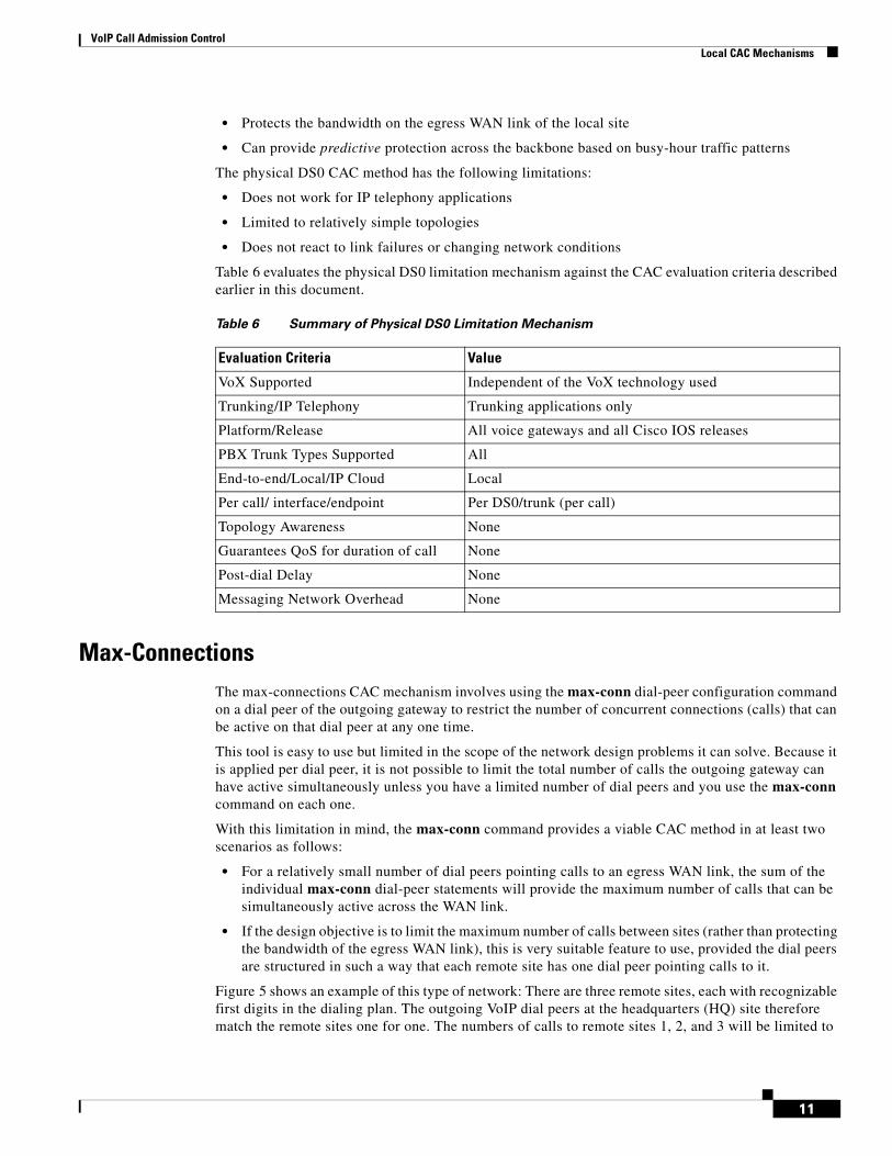
Table 6 evaluates the physical DS0 limitation mechanism against the CAC evaluation criteria described earlier in this document.
Max-ConnectionsThe max-connections CAC mechanism involves using the max-conn dial-peer configuration command on a dial peer of the outgoing gateway to restrict the number of concurrent connections (calls) that can be active on that dial peer at any one time.
This tool is easy to use but limited in the scope of the network design problems it can solve. Because it is applied per dial peer, it is not possible to limit the total number of calls the outgoing gateway can have active simultaneously unless you have a limited number of dial peers and you use the max-conn command on each one.
With this limitation in mind, the max-conn command provides a viable CAC method in at least two scenarios as follows:
• For a relatively small number of dial peers pointing calls to an egress WAN link, the sum of the individual max-conn dial-peer statements will provide the maximum number of calls that can be simultaneously active across the WAN link.
• If the design objective is to limit the maximum number of calls between sites (rather than protecting the bandwidth of the egress WAN link), this is very suitable feature to use, provided the dial peers are structured in such a way that each remote site has one dial peer pointing calls to it.
Figure 5 shows an example of this type of network: There are three remote sites, each with recognizable first digits in the dialing plan. The outgoing VoIP dial peers at the headquarters (HQ) site therefore match the remote sites one for one. The numbers of calls to remote sites 1, 2, and 3 will be limited to
Table 6 Summary of Physical DS0 Limitation Mechanism
Evaluation Criteria Value
VoX Supported Independent of the VoX technology used
Trunking/IP Telephony Trunking applications only
Platform/Release All voice gateways and all Cisco IOS releases
PBX Trunk Types Supported All
End-to-end/Local/IP Cloud Local
Per call/ interface/endpoint Per DS0/trunk (per call)
Topology Awareness None
Guarantees QoS for duration of call None
Post-dial Delay None
Messaging Network Overhead None
11
VoIP Call Admission ControlLocal CAC Mechanisms
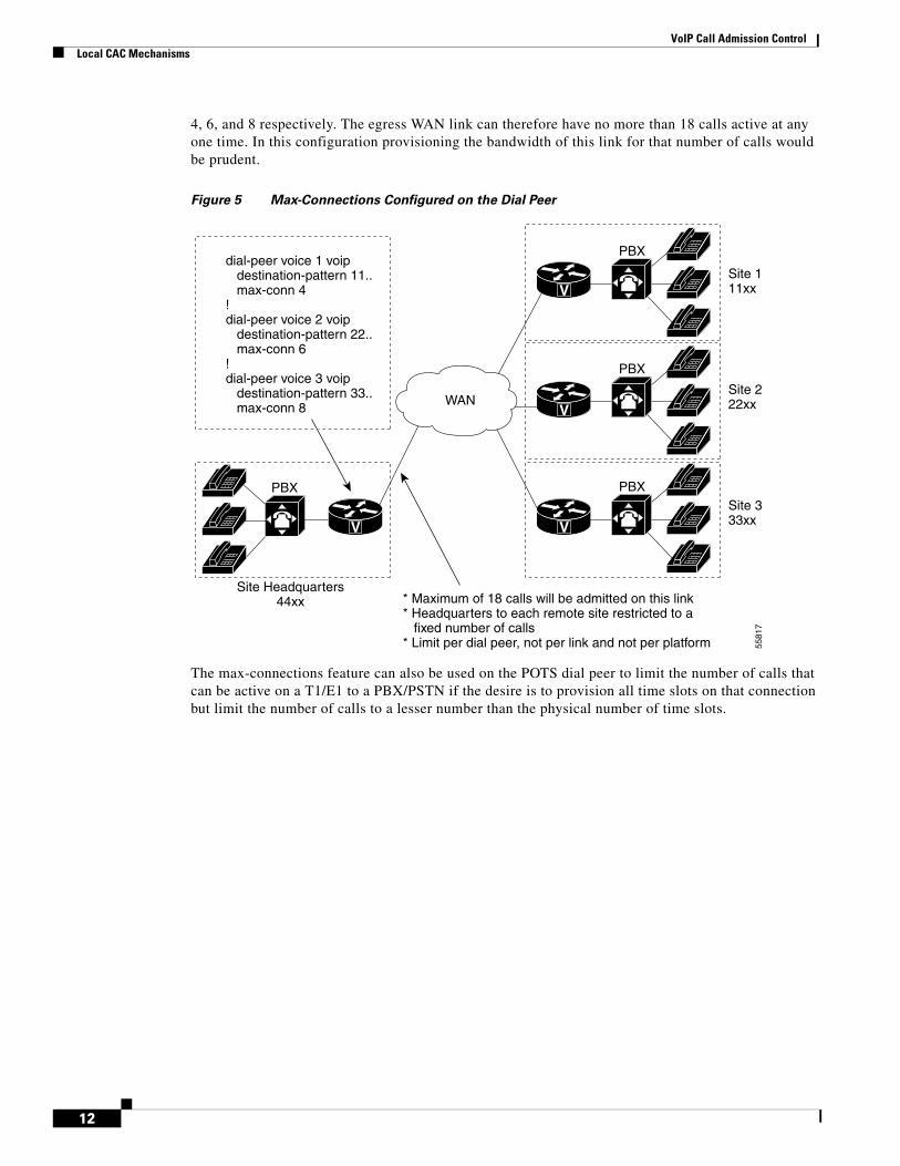
4, 6, and 8 respectively. The egress WAN link can therefore have no more than 18 calls active at any one time. In this configuration provisioning the bandwidth of this link for that number of calls would be prudent.
Figure 5 Max-Connections Configured on the Dial Peer
The max-connections feature can also be used on the POTS dial peer to limit the number of calls that can be active on a T1/E1 to a PBX/PSTN if the desire is to provision all time slots on that connection but limit the number of calls to a lesser number than the physical number of time slots.
V
V
VV
Site 111xx
Site 222xx
Site 333xx
Site Headquarters44xx
PBX
PBX
PBX
PBX
5581
7
WAN
* Maximum of 18 calls will be admitted on this link* Headquarters to each remote site restricted to a fixed number of calls* Limit per dial peer, not per link and not per platform
dial-peer voice 1 voip destination-pattern 11.. max-conn 4!dial-peer voice 2 voip destination-pattern 22.. max-conn 6!dial-peer voice 3 voip destination-pattern 33.. max-conn 8
12
VoIP Call Admission ControlLocal CAC Mechanisms
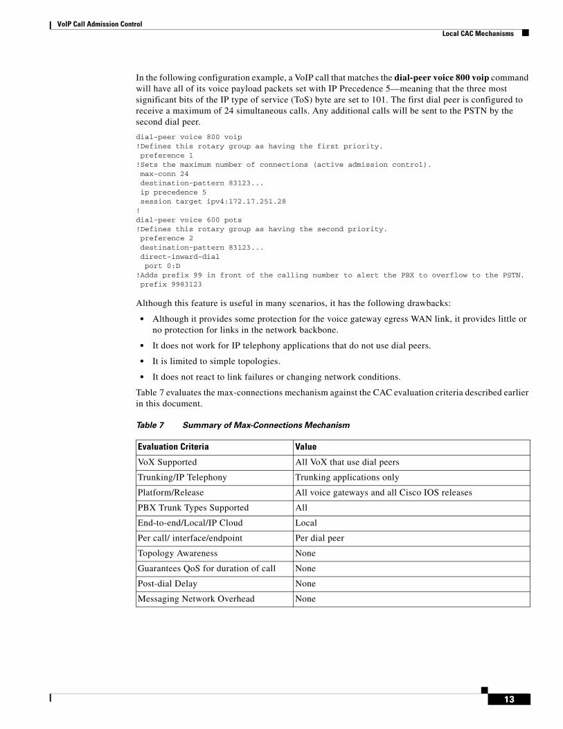
In the following configuration example, a VoIP call that matches the dial-peer voice 800 voip command will have all of its voice payload packets set with IP Precedence 5—meaning that the three most significant bits of the IP type of service (ToS) byte are set to 101. The first dial peer is configured to receive a maximum of 24 simultaneous calls. Any additional calls will be sent to the PSTN by the second dial peer.
dial-peer voice 800 voip!Defines this rotary group as having the first priority. preference 1!Sets the maximum number of connections (active admission control). max-conn 24 destination-pattern 83123... ip precedence 5 session target ipv4:172.17.251.28 !dial-peer voice 600 pots!Defines this rotary group as having the second priority. preference 2 destination-pattern 83123... direct-inward-dial port 0:D!Adds prefix 99 in front of the calling number to alert the PBX to overflow to the PSTN. prefix 9983123
Although this feature is useful in many scenarios, it has the following drawbacks:
• Although it provides some protection for the voice gateway egress WAN link, it provides little or no protection for links in the network backbone.
• It does not work for IP telephony applications that do not use dial peers.
• It is limited to simple topologies.
• It does not react to link failures or changing network conditions.
Table 7 evaluates the max-connections mechanism against the CAC evaluation criteria described earlier in this document.
Table 7 Summary of Max-Connections Mechanism
Evaluation Criteria Value
VoX Supported All VoX that use dial peers
Trunking/IP Telephony Trunking applications only
Platform/Release All voice gateways and all Cisco IOS releases
PBX Trunk Types Supported All
End-to-end/Local/IP Cloud Local
Per call/ interface/endpoint Per dial peer
Topology Awareness None
Guarantees QoS for duration of call None
Post-dial Delay None
Messaging Network Overhead None
13

VoIP Call Admission ControlLocal CAC Mechanisms
Voice BandwidthIn VoFR configurations, a frame-relay voice-bandwidth interface configuration command is used in the FrameRelay map-class to set aside bandwidth for VoFR calls. This method of bandwidth provisioning operates in a way similar to the way in which the IP RTP Priority and Low Latency Queueing (LLQ) features reserve bandwidth for general traffic flows. However, the frame-relay voice-bandwidth command also provides CAC, which the general queueing features do not.
The frame-relay voice-bandwidth command can provide CAC because VoFR is a Layer 2 technology. By looking at the FRF.11 (voice) or FRF.3.1 (data) headers, the Frame Relay software is able to determine which frames are voice frames and which are data frames. The software also knows which frames belong to which voice call because subsequent fields in the header carry Channel Identification (CID) and payload information. Because the frame-relay voice-bandwidth command sets aside bandwidth for voice, it can also deny the next call if that one additional call will cause the total bandwidth allocated to voice to be exceeded.
This CAC method is of use only if VoFR is a viable technology in your network. It should also be noted that the voice-bandwidth size defaults to 0 so that if no bandwidth reservation is specified, no voice calls are allowed over the WAN link. Do not include signaling traffic in the bandwidth you specify with this command—just voice payload traffic.
The following configuration example provides CAC for VoFR by provisioning 24 kbps, which is enough for two G.729 calls at 10.4 kbps each.
interface Serial0/0 encapsulation frame-relay no fair-queue frame-relay traffic-shaping! interface Serial0/0.1 point-to-point frame-relay interface-dlci 16 class vofr!map-class frame vofr frame cir 60000 frame bc 600 frame frag 80 frame fair-queue!24 kbps is enough for two G.729 calls at 10.4 kbps each. frame-relay voice-bandwidth 24000
Table 9 evaluates the voice-bandwidth mechanism against the CAC evaluation criteria described earlier in this document.
Table 8 Summary of Voice-Bandwidth Mechanism
Evaluation Criteria Value
VoX Supported VoFR
Trunking/IP Telephony Trunking applications only
Platform/Release Cisco 2600s, 3600s, 3810, and 7200 router; Cisco IOS Release 12.0(4)T
PBX Trunk Types Supported All
End-to-end/Local/IP Cloud Local
Per call/ interface/endpoint Per call, per PVC
Topology Awareness None
14

VoIP Call Admission ControlLocal CAC Mechanisms
Trunk ConditioningTrunk conditioning provides more functionality than just CAC, but only the CAC aspects will be discussed here. It can be used in connection trunk networks (networks with permanent voice connections across the VoX portion of the network) to monitor the state of the VoX connection and busy back the trunk to the originating PBX if the VoX connection should fail.
This feature is limited in scope because it applies to connection trunk networks only. However, most of the other CAC features apply only to switched networks.
Implementing CAC on a connection trunk configuration is a slightly different problem than implementing it for switched networks because the VoX connections between the two gateways are permanent, as shown in Figure 6. The bandwidth is therefore already established and allocated, and must be available or the connection trunk connections will not be established properly.
Figure 6 Trunk Conditioning
The unique attribute of trunk conditioning compared to other CAC features is that it has visibility not only into the condition of the WAN end-to-end, but also into the condition of the POTS connection on the terminating side of the network. In Figure 6, if any one of the legs A, B, C, or D should fail, the outgoing gateway will know this and can busy back the trunk to the originating PBX to trigger rerouting capability at the source. This information is carried as part of the keepalive messages that are generated on connection trunk configurations.
You can tune the precise bit pattern that will be generated to the originating PBX. The ABCD bits can be configured to specific busy or out-of-service (OOS) indications that the originating PBX will recognize and act upon.
Trunk conditioning is therefore not a call-by-call feature, as are those that discussed so far. It is a PBX trunk busy-back (or OOS) feature. If there is a failure in the WAN, the trunk to the PBX is taken out of service so that no calls can be made across that trunk until the WAN connectivity is recovered.
Table 9 evaluates the trunk conditioning mechanism against the CAC evaluation criteria described earlier in this document.
Guarantees QoS for duration of call None
Post-dial Delay None
Messaging Network Overhead None
Table 8 Summary of Voice-Bandwidth Mechanism
Evaluation Criteria Value
V VWAN
5581
8
PSTN
PBX PBX
A C D
B
Connection trunk
15

VoIP Call Admission ControlLocal CAC Mechanisms
Local Voice BusyoutSeveral CAC mechanisms are called trunk busy-back features. The first one we encountered was trunk conditioning in the previous section. That feature operates on connection trunk networks only. Similar functionality is needed for switched networks, and LVBO is the first of two features that achieve this.
LVBO allows you to take a PBX trunk connection to the attached gateway completely out of service when WAN conditions are considered unsuitable to carry voice traffic. This technique has the following advantages:
• Not every call must be rejected individually and incur a postdial delay.
• Prevents the need for hairpinning rejected calls back to the originating PBX, using up multiple DS0 slots for a single call.
• Works well to redirect rejected calls with PBXs that either do not have the intelligence or are not configured appropriately.
• Solves the hairpinning problem of the PBX putting the call back onto a third DS0 on the same T1/E1 line to the gateway that has already rejected the call and hairpinned it (a condition called tromboning). CCS trunk types manage this hairpinning problem because cause code information can be returned to the PBX that triggers rerouting logic. However on CAS trunks the PBX does not know what went wrong, and unless digits are manipulated in the gateway, the PBX cannot easily make a decision to reroute the call over a different trunk group.
LVBO provides the outgoing gateway with the ability to monitor the state of various network interfaces, both LAN and WAN, and busy back the trunk to the PBX if any of the monitored links should fail. Up to 32 interfaces can be monitored; if either one of or all of the interfaces change state, the gateway can be configured to busy back the trunk to the PBX. The reason this feature is called local voice busyout is because only local links can be monitored. This feature has no visibility into the network beyond the link of the local gateway.
LVBO in current software works on CAS and analog PBX/PSTN trunks only. On CCS trunks, the cause code functionality can be used to inform the PBX switch to redirect a rejected call. LVBO can be configured in one of two ways:
Table 9 Summary of Trunk Conditioning Mechanism
Evaluation Criteria Value
VoX Supported VoIP/H.323, VoFR, VoATM (connection trunk configurations only)
Trunking/IP Telephony Trunking applications only
Platform/Release Cisco 2600 and 3600 series routers, and Cisco MC3810 multiaccess concentrators; Cisco IOS Release 12.1(3)T
PBX Trunk Types Supported Analog and CAS
End-to-end/Local/IP Cloud Local
Per call/ interface/endpoint Per telephony interface
Topology Awareness None
Guarantees QoS for duration of call None
Post-dial Delay None
Messaging Network Overhead None; uses preexisting connection trunk keepalives
16
VoIP Call Admission ControlLocal CAC Mechanisms
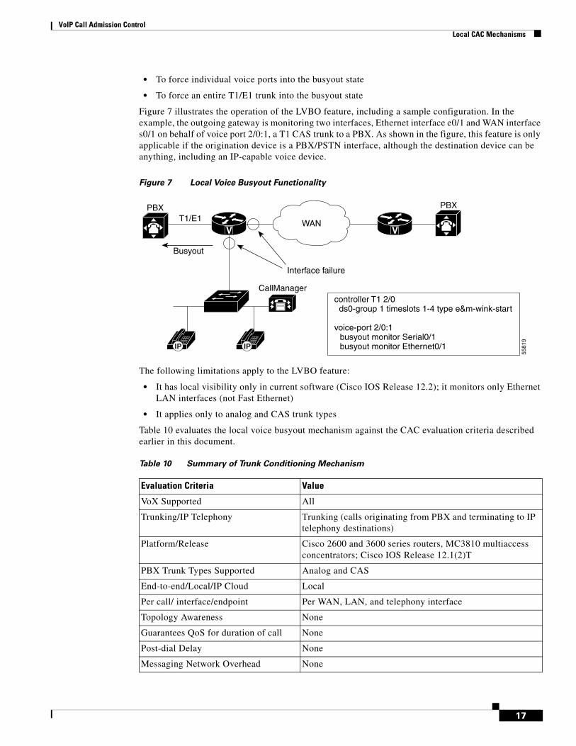
• To force individual voice ports into the busyout state
• To force an entire T1/E1 trunk into the busyout state
Figure 7 illustrates the operation of the LVBO feature, including a sample configuration. In the example, the outgoing gateway is monitoring two interfaces, Ethernet interface e0/1 and WAN interface s0/1 on behalf of voice port 2/0:1, a T1 CAS trunk to a PBX. As shown in the figure, this feature is only applicable if the origination device is a PBX/PSTN interface, although the destination device can be anything, including an IP-capable voice device.
Figure 7 Local Voice Busyout Functionality
The following limitations apply to the LVBO feature:
• It has local visibility only in current software (Cisco IOS Release 12.2); it monitors only Ethernet LAN interfaces (not Fast Ethernet)
• It applies only to analog and CAS trunk types
Table 10 evaluates the local voice busyout mechanism against the CAC evaluation criteria described earlier in this document.
WAN
CallManager
5581
9
PBXT1/E1
PBX
IP IP
Busyout
Interface failure
controller T1 2/0 ds0-group 1 timeslots 1-4 type e&m-wink-start
voice-port 2/0:1busyout monitor Serial0/1busyout monitor Ethernet0/1
V V
Table 10 Summary of Trunk Conditioning Mechanism
Evaluation Criteria Value
VoX Supported All
Trunking/IP Telephony Trunking (calls originating from PBX and terminating to IP telephony destinations)
Platform/Release Cisco 2600 and 3600 series routers, MC3810 multiaccess concentrators; Cisco IOS Release 12.1(2)T
PBX Trunk Types Supported Analog and CAS
End-to-end/Local/IP Cloud Local
Per call/ interface/endpoint Per WAN, LAN, and telephony interface
Topology Awareness None
Guarantees QoS for duration of call None
Post-dial Delay None
Messaging Network Overhead None
17
VoIP Call Admission ControlMeasurement Based CAC Mechanisms
Measurement Based CAC MechanismsThis section of the document focuses on the following measurement-based CAC techniques:
• Advanced Voice Busyout
• PSTN Fallback
These are the first of two types of CAC mechanisms that add visibility into the network itself in addition to providing local information on the outgoing gateway as discussed in the preceding sections.
Before we discuss the actual features within this category, some background information on Service Assurance Agent (SAA) probes is necessary, because this is the underlying technique employed by the measurement-based CAC methods. SAA probes traverse the network to a given IP destination and measure the loss and delay characteristics of the network along the path traveled. These values are returned to the outgoing gateway to use in making a decision on the condition of the network and its ability to carry a voice call.
Note the following attributes of measurement-based CAC mechanisms that are derived from their use of SAA probes:
• Because an SAA probe is an IP packet traveling to an IP destination, all measurement-based CAC techniques apply to VoIP only (including VoIP over Frame Relay and VoIP over ATM networks).
• As probes are sent into the network, a certain amount of overhead traffic is produced in gathering the information needed for CAC.
• If the CAC decision for a call must await a probe to be dispatched and returned, there is some small additional postdial delay for the call. This should be insignificant in a properly designed network.
The Cisco Service Assurance AgentSAA is a network management feature integrated in Cisco IOS software that provides a mechanism for network congestion analysis. It also underlies a multitude of other Cisco IOS features. It was not implemented for the purpose of accomplishing CAC, nor is it a part of the CAC suite. But its capabilities to measure network delay and packet loss are useful as building blocks on which to base CAC features. The SAA feature is an extenstion to Response Time Reporter (RTR) feature found in earlier releases of Cisco IOS software.
SAA probes do not provide any bandwidth information, either configured or available. However, if bandwidth across a link anywhere in the path that the voice call will follow is oversubscribed, it is reasonable to assume that the packet delay and loss values that the probe returns will indeed reflect this condition, even if indirectly.
SAA Probes Versus Pings
SAA probes are similar in concept to the popular ping IP connectivity mechanism, but are far more sophisticated. SAA packets can be built and customized to mimic the type of traffic for which they are measuring the network—in this case a voice packet. A ping packet is almost by definition a best-effort packet, and even if the IP precedence is set, it does not resemble a voice packet in size or protocol. Nor will the QoS mechanisms deployed in the network classify and treat a ping packet as a voice packet. The delay and loss experienced by a ping are therefore a very crude worst-case measure of the treatment a voice packet might be subject to while traversing the very same network. With the penetration of sophisticated QoS mechanisms in network backbones, a ping becomes unusable as a practical indication of the capability of the network to carry voice.
18

VoIP Call Admission ControlMeasurement Based CAC Mechanisms
SAA Protocol
The SAA protocol is a client/server protocol defined on UDP. The client builds and sends the probe, and the target device (with the RTR Responder enabled) returns the probe to the sender. The SAA probes used for CAC go out randomly on ports selected from within the top end of the audio UDP-defined port range (16384 to 32767); they use a packet size based on the codec the call will use. IP precedence can be set if desired, and a full RTP/UDP/IP header is used like the header a real voice packet would carry. By default the SAA probe uses the RTCP port (the odd RTP port number), but it can also be configured to use the RTP media port (the even RTP port number) if desired.
SAA was introduced on selected platforms in Cisco IOS Release 12.0(7)T. The higher-end Cisco router platforms tend to support it (for example, the Cisco 7200 and 7500 series), and the lower-end platforms tend not to support it (for example, the Cisco 1750 router). At the time this document was written, neither the Cisco cable access routers nor the IP phones support SAA probes or respond to SAA probes.
Calculated Planning Impairment Factor
The ITU standardizes network Transmission Impairments in ITU G.113. This standard defines the term Calculated Planning Impairment Factor (ICPIF), which is a calculation based on network delay and packet loss figures. ICPIF yields a single value that can be used as a gauge of network impairment.
ITU G.113 provides the following interpretations of specific ICPIF values:
• 5: Very good
• 10: Good
• 20: Adequate
• 30: Limiting case
• 45: Exceptional limiting case
• 55: Customers likely to react strongly
SAA probe delay and loss information is used in calculating an ICPIF value that is then used as a threshold for CAC decisions, based either on the ITU interpretation described or on the requirements of an individual customer network.
Advanced Voice BusyoutAVBO is an enhancement to LVBO. Although LVBO provides for busyout based on local conditions of the outgoing gateway, AVBO adds the capability to trigger an SAA probe to one or more configured IP destinations. The information returned by the probe—either the explicit loss or delay values, or the ICPIF congestion threshold—can be used to trigger a busyout of the connection to the PBX.
AVBO therefore introduces the ability to busy out a PBX trunk, or individual voice ports, based on the current conditions of the IP network. This capability is illustrated in Figure 8.
19

VoIP Call Admission ControlMeasurement Based CAC Mechanisms
Figure 8 Advanced Voice Busyout
The following configuration example shows a sample configuration of AVBO on a T1 CAS trunk to a PBX.
controller T1 2/0 ds0-group 1 timeslots 1-4 type e&m-immediate-start!voice-port 2/0:1 voice-class busyout 4!voice class busyout 4 busyout monitor Serial0/1 busyout monitor Ethernet0/1 busyout monitor probe 1.6.6.48 codec g729r8 icpif 10
When using advanced voice busyout, you should remember the following restrictions and limitations:
• Busyout results based on probes (measurement-based) are not absolute—there are therefore conditions where a false positive will happen.
• The IP addresses monitored by the probes are statically configured (as shown in the configuration example). It is necessary to ensure, manually, that these IP addresses are indeed the destinations to which calls are being made. There is no automatic coordination between the probe configuration and the actual IP destinations to which VoIP dial peers or a gatekeeper may direct calls.
• The destination node (the device that owns the IP address to which the probe is sent) must support an SAA responder.
• This feature cannot busy back the local PBX trunk based on the state of the telephony trunk on the remote node; it monitors IP network only.
• SAA probe-based features will not work well in networks where traffic load fluctuates dramatically in a short period of time.
• As with LVBO, this feature can be applied only to analog and CAS trunks; CCS trunks are not yet supported.
Table 11 evaluates the AVBO mechanism against the CAC evaluation criteria described earlier in this document.
WAN
5582
0
PBXT1/E1
PBX
IP IP IP IP
Busyout
CallManager CallManager
Congestion detection (ICPIF, or delay/loss exceed thresholds)to specific IP destinations
V V
20
VoIP Call Admission ControlMeasurement Based CAC Mechanisms
PSTN FallbackThe name PSTN fallback is to some extent a misnomer because a call can be redirected to any of the rerouting options discussed earlier in this document, not to only the PSTN. And even if a call is redirected to the PSTN, redirection can be done by the outgoing gateway or by the PBX attached to the outgoing gateway, depending on the configuration. For this reason, this feature is sometimes referred to as VoIP fallback.
Unlike AVBO, PSTN fallback is a per-call CAC mechanism: PSTN fallback does not busy out any trunks or provide any general indication to the attached PBX that the IP cloud cannot take calls. The CAC decision is triggered only when a call setup is attempted.
Because PSTN fallback is based on SAA probes, it has all the benefits and drawbacks of a measurement-based technique. It is unusually flexible in that it can make CAC decisions based on any type of IP network, including the Internet. All IP networks will carry the SAA probe packet as just another IP packet. Therefore it does not matter if the customer backbone network comprises one or more service provider (SP) networks, the Internet, or any combination of these network types. The only requirement is that the destination device (the owner of the IP address to which the probe is sent) support SAA responder functionality.
This destination device is should be part of the customer network at the destination site, with an SP backbone in between. PSTN fallback therefore cannot be used directly with IP phones and PC-based VoIP application destinations, but it can be used indirectly if these destinations are behind a Cisco IOS router that can support the SAA responder. The destination device itself need not support the PSTN fallback feature (it is an outgoing gateway feature only)—only the SAA probe responder is needed.
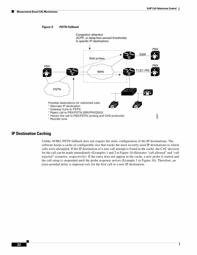
SAA Probes Used for PSTN Fallback
As shown in Figure 9, when a call is attempted at the outgoing gateway, the network congestion values for the IP destination will be used to allow or reject the call. The network congestion values for delay, loss, or ICPIF are provided by sending an SAA probe to the IP destination the call is trying to reach. The threshold values for rejecting a call are configured at the outgoing gateway.
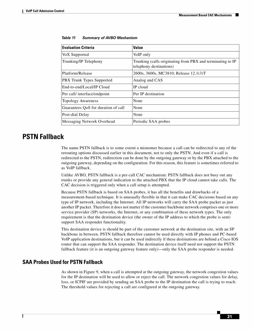
Table 11 Summary of AVBO Mechanism
Evaluation Criteria Value
VoX Supported VoIP only
Trunking/IP Telephony Trunking (calls originating from PBX and terminating to IP telephony destinations)
Platform/Release 2600s, 3600s, MC3810; Release 12.1(3)T
PBX Trunk Types Supported Analog and CAS
End-to-end/Local/IP Cloud IP cloud
Per call/ interface/endpoint Per IP destination
Topology Awareness None
Guarantees QoS for duration of call None
Post-dial Delay None
Messaging Network Overhead Periodic SAA probes
21
VoIP Call Admission ControlMeasurement Based CAC Mechanisms
Figure 9 PSTN Fallback
IP Destination Caching
Unlike AVBO, PSTN fallback does not require the static configuration of the IP destinations. The software keeps a cache of configurable size that tracks the most recently used IP destinations to which calls were attempted. If the IP destination of a new call attempt is found in the cache, the CAC decision for the call can be made immediately (Examples 1 and 2 in Figure 10 illustrates “call allowed” and “call rejected” scenarios, respectively). If the entry does not appear in the cache, a new probe is started and the call setup is suspended until the probe response arrives (Example 3 in Figure 10). Therefore, an extra postdial delay is imposed only for the first call to a new IP destination.
5582
1
PBXT1/E1 PRI
E&M
PBX
PBX
IP IP
Congestion detection (ICPIF, or delay/loss exceed thresholds)to specific IP destinations
WAN
PSTN
SAA probes
Possible destinations for redirected calls:* Alternate IP destination* Gateway trunk to PSTN* Reject call to PBX/PSTN (BRI/PRI/QSIG)* Hairpin the call to PBX/PSTN (analog and CAS protocols)* Reorder tone
V V
V
22

VoIP Call Admission ControlMeasurement Based CAC Mechanisms
Figure 10 PSTN Fallback Call Setup
Once an IP destination has been entered into the cache, a periodic probe with a configurable timeout value will be sent to that destination to refresh the information in the cache. If no further calls are made to this IP destination, the entry will age out of the cache and probe traffic to that destination will be discontinued. PSTN fallback thus dynamically adjusts the probe traffic to the IP destinations that are actively seeing call activity.
SAA Probe Format
Each probe consists of multiple packets—a configurable parameter of the feature. The delay, loss, and ICPIF values entered into the cache for the IP destination will be averaged from all the responses.
If the call uses the G.729 and G.711 codecs, the probe packet sizes will mimic those of a voice packet for that codec. Other codecs will use G.711-like probes. In Cisco IOS software releases later than Release 12.1(3)T, other codec choices may also be supported with their own exact probes.
The IP Precedence of the probe packets can also be configured in order to mimic the priority of a voice packet more closely. This parameter should be set equal to the IP precedence used for other voice media packets in the network.
PSTN Fallback Configuration
PSTN fallback configuration applies only to calls initiated by the outgoing gateway; it has no bearing on calls received by the gateway. The destination node (often the terminating gateway, but not necessarily so) should be configured with the SAA Responder feature. In most networks, gateways
WAN
Call Setup
Call Setup
Call Setup
Call Setup
Values OK
Call Reject/Hairpin
SAA Probe
SAA Response
Call Setup
Call Setup
Call Setup
Cache entry for IP address found,values OK
Cache entry for IP address found,values not OK – no secondary dial peerexists
No cache entry for IP address found
Exa
mpl
e 1
Exa
mpl
e 2
Exa
mpl
e 3
5582
2
V V
23

VoIP Call Admission ControlMeasurement Based CAC Mechanisms
generate calls to each other, so that every gateway is both an outgoing gateway and a terminating gateway. But in some networks (for example, SP networks), call traffic direction is occasionally one-sided, either outgoing or incoming.
PSTN fallback configuration is done at the global level and therefore applies to all calls attempted by the gateway. You cannot selectively apply PSTN fallback only to calls initiated by certain PSTN/PBX interfaces.
To turn on PSTN fallback, enter the following global configuration commands:
• Outgoing gateway: the call fallback command
• Destination node: the rtr responder command
The call feedback command has the following keywords with the following default values:
PSTN Fallback Scalability
Customers with large networks are often concerned about PSTN fallback causing a large amount of probe traffic on their networks. In smaller networks, the terminating gateways can be used as the probe destination nodes. In other words, the IP addresses kept in the cache of the outgoing gateway will be those of the terminating gateways to which call traffic is sent.
However, for large sites or campus sites that may have multiple terminating gateways, or for sites with IP phone or PC-based applications as destinations, or for sites that have a WAN edge router that is separate from the terminating gateway, the call traffic destination IP addresses can be mapped to a much smaller set of probe destinations that will be kept in the cache as follows.
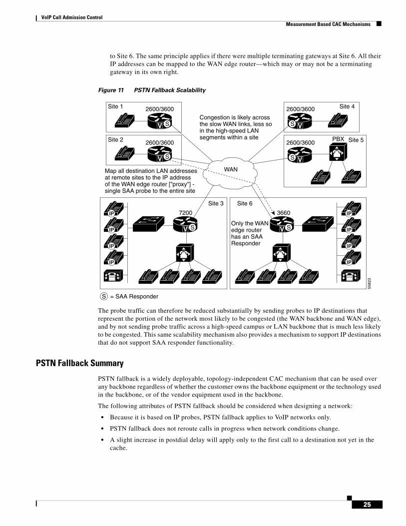
• Consider an example based on Figure 11. There are a large number of IP Phones at Site 6, each one having a unique IP address. If Site 1 calls an IP phone at Site 6, the cache at Site 1 need not to contain an entry for each separate IP destination at Site 6 and send a separate probe for each IP address. All IP call destinations at Site 6 can be mapped to the IP address of the WAN edge router of Site 6 so that a single probe from Site 1 to Site 6 can probe CAC information for all calls destined
call fallback Command Keyword Keyword PurposeDefault Value
cache-size Configure cache size 128
cache-timeout Configure cache timeout 600s
instantaneous-value-weight Configure the instantaneous value weight 66
jitter-probe Configure jitter probe parameters
• num-packets Configure the number of the packets in the probe 15
• precedence Configure the precedence of the packets in the probe 2
• priority-queue Have the probes be sent through the voice PQ off
key-chain Configure MD5 key chain none
map Configure IP mapping none
probe-timeout Configure probe timeout 30s
threshold Configure ICPIF or delay/loss threshold
• delay n loss m Configure delay threshold none
• icpif n Configure ICPIF threshold 10
24
VoIP Call Admission ControlMeasurement Based CAC Mechanisms
to Site 6. The same principle applies if there were multiple terminating gateways at Site 6. All their IP addresses can be mapped to the WAN edge router—which may or may not be a terminating gateway in its own right.
Figure 11 PSTN Fallback Scalability
The probe traffic can therefore be reduced substantially by sending probes to IP destinations that represent the portion of the network most likely to be congested (the WAN backbone and WAN edge), and by not sending probe traffic across a high-speed campus or LAN backbone that is much less likely to be congested. This same scalability mechanism also provides a mechanism to support IP destinations that do not support SAA responder functionality.
PSTN Fallback Summary
PSTN fallback is a widely deployable, topology-independent CAC mechanism that can be used over any backbone regardless of whether the customer owns the backbone equipment or the technology used in the backbone, or of the vendor equipment used in the backbone.
The following attributes of PSTN fallback should be considered when designing a network:
• Because it is based on IP probes, PSTN fallback applies to VoIP networks only.
• PSTN fallback does not reroute calls in progress when network conditions change.
• A slight increase in postdial delay will apply only to the first call to a destination not yet in the cache.
V V
PBX
VV
V
IP
IP
IP
IP
IP
IP
IP
IP
Site 1
Site 2
Site 3 Site 6
Site 4
Site 5
2600/3600
2600/3600
2600/3600
2600/3600
Congestion is likely acrossthe slow WAN links, less soin the high-speed LANsegments within a site
Map all destination LAN addressesat remote sites to the IP addressof the WAN edge router ["proxy"] -single SAA probe to the entire site
WAN
V
S
SS
S
S S
S
Only the WANedge router has an SAAResponder
= SAA Responder
5582
3
7200 3660
25
VoIP Call Admission ControlResource-Based CAC Mechanisms
• There is no interaction between the SAA probe timer and the H.225 timer setting: The SAA probe occurs before the H.323 call setup is sent to the destination, and the H.225 timer occurs after H.323 call setup is sent.
• PSTN fallback is measurement-based, and therefore not absolute: It will perform well in steady traffic that has a gradual ramp-up and ramp-down, but poorly in quickly fluctuating traffic with a bursty ramp-up and ramp-down.
• An erroneous CAC decision could be reached based on noncurrent information due to the periodic nature of the probes.
• Proxy destinations for the probes can be used by mapping destination IP addresses to a smaller number of IP addresses of the nodes located between the outgoing gateway and the terminating gateways.
• No bandwidth measurements are taken by the probes—only delay and loss measurements.
• MD5 key chain authentication can be configured for security to ensure that probes are initiated only by trusted sources, which will circumvent “denial-of-service” type attacks by untrusted sources initiating large volumes of probes.
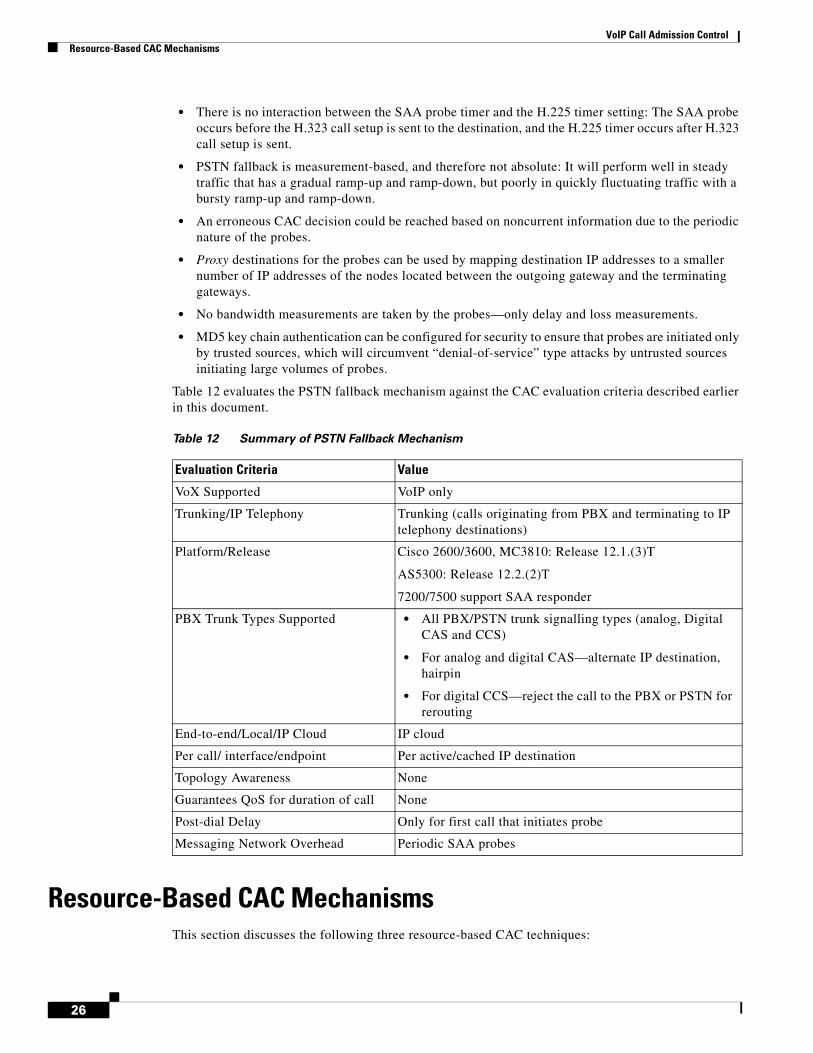
Table 12 evaluates the PSTN fallback mechanism against the CAC evaluation criteria described earlier in this document.
Resource-Based CAC MechanismsThis section discusses the following three resource-based CAC techniques:
Table 12 Summary of PSTN Fallback Mechanism
Evaluation Criteria Value
VoX Supported VoIP only
Trunking/IP Telephony Trunking (calls originating from PBX and terminating to IP telephony destinations)
Platform/Release Cisco 2600/3600, MC3810: Release 12.1.(3)T
AS5300: Release 12.2.(2)T
7200/7500 support SAA responder
PBX Trunk Types Supported • All PBX/PSTN trunk signalling types (analog, Digital CAS and CCS)
• For analog and digital CAS—alternate IP destination, hairpin
• For digital CCS—reject the call to the PBX or PSTN for rerouting
End-to-end/Local/IP Cloud IP cloud
Per call/ interface/endpoint Per active/cached IP destination
Topology Awareness None
Guarantees QoS for duration of call None
Post-dial Delay Only for first call that initiates probe
Messaging Network Overhead Periodic SAA probes
26

VoIP Call Admission ControlResource-Based CAC Mechanisms
• Resource Availability Indication
• Gatekeeper Zone Bandwidth
• Resource Reservation Protocol
Like the measurement-based CAC techniques, these techniques add visibility into the network itself in addition to the local information on the outgoing gateway that can be used for CAC as discussed in the preceding sections.
Resource Calculation Versus Resource ReservationThere are two types of resource-based CAC mechanisms:
• Those that monitor the use of certain resources and calculate a value that will affect the CAC decision
• Those that reserve resources for the call
The reservation mechanisms are the only ones that can guarantee QoS for the duration of the call. All other CAC mechanisms (local, measurement-based, and resource calculation-based) simply make a one-time decision prior to call setup based on knowledge of network conditions at that time.
The following resources are of interest to voice calls:
• DS0 time slot on the originating and terminating TDM trunks
• DSP resources on the originating and terminating gateways
• CPU use of the nodes—typically the gateways
• Memory use of the nodes—typically the gateways
• Bandwidth availability on one or more links in the path the call will take
In current Cisco IOS software (Release 12.2), the resource calculation CAC methods discussed in the following sections consider the DS0 and DSP availability of the terminating gateway (RAI), along with bandwidth at a high level (gatekeeper zone bandwidth management). The only current resource reservation mechanism (RSVP) considers only bandwidth availability.
Resource Availability IndicationRAI is an H.323v2 feature that describes a RAS message that is sent from the terminating gateway to the gatekeeper to deliver information about the current ability of the gateway to take more calls. The gatekeeper does not have knowledge of the individual resources or the type of resources that the gateway considers. It is a simple yes or no toggle indication sent by the terminating gateway to control whether subsequent voice calls are routed to the gateway.
As a CAC mechanism, RAI is unique in its ability to provide information on the terminating POTS connection. Other mechanisms we have discussed in this document enable CAC decisions based on local information at the outgoing gateway, and on the condition of the IP cloud between the outgoing gateway and terminating gateways. No other CAC mechanism is able to look at the availability of resources to terminate the POTS call at the terminating gateway—this is the value RAI brings to the table.
Because it is an indication between a gateway and gatekeeper, RAI applies only to H.323 voice networks that use a gatekeeper design. RAI is also unique in that the CAC decision is controlled by the terminating gateway. In all the other methods, the CAC decision is controlled by the outgoing gateway or by the gatekeeper.
27

VoIP Call Admission ControlResource-Based CAC Mechanisms
Gateway Calculation of Resources
The calculation to reach the yes/no decision is performed on the gateway. Different gateway platforms may use different algorithms. The H.323 standard does not prescribe the calculation nor the resources to include in the calculation. It merely specifies the RAI message format and the fact that the gatekeeper must stop routing calls to a gateway that has indicated an inability to receive further calls until such time as the gateway informs the gatekeeper that it can take calls again.
To gauge resource availability for a call for the Cisco 2600 and 3600 series routers, the calculation algorithm considers each call as a unit according to the following formula:
• Each free DS0 is a unit
• Each high-complexity DSP is two units
• Each medium-complexity DSP is four units
RAI is calculated per platform, not per T1/E1 interface or per card (per network module, or specifically per NMM-HDV in the case of the Cisco 2600 and 3600 series routers). Only DS0s reachable through a VoIP dial peer are included in the calculation.
Where and How RAI Is Used in Service Provider Networks
RAI is an indispensable feature in SP networks that provide VoIP calling services such as debit and credit card calling and VoIP long-distance phone service. The general structure of these networks is shown in Figure 12.
Figure 12 Service Provider VoIP Network Topology
Around the world there are POPs where racks of gateways (typically Cisco AS5300 access servers) connect to the PSTN with T1/E1 trunks—frequently PRI trunks. The call routing is managed through several levels of gatekeepers as shown in Figure 12. Call volume is high, and these gateways handle voice traffic only—no data traffic other than minimal IP routing and network management traffic.
SP VoIPBackbone
GK GK
GK GK GK GK
directory-GKHSRP
GK GK
directory-GKHSRP
VV
VV
V
VV
VV
V
PSTN PSTN
AltWest GK West GK AltEast GK East GK
5582
4
28

VoIP Call Admission ControlResource-Based CAC Mechanisms
When a customer on the West Coast dials into the network and dials a number on the East Coast, the East Coast gatekeeper must select an East Coast gateway that has an available PSTN trunk to terminate the call; otherwise, the customer call will fail. If the call fails, either the outgoing gateway must retry the call or the customer must redial the call. In either case, there is no guarantee that the same out-of-capacity terminating gateway will not be selected again.
Both scenarios are inefficient and provide poor customer service. It is important therefore that calls are not routed by the gatekeeper to a terminating gatekeeper that cannot terminate the call—not because of IP capacity in this case, but because of PSTN trunk capacity.
In general, calls will be load-balanced by the gatekeeper across the terminating gateways in its zone. But the gateways could have different levels of T1/E1 capacity and, by sheer load balancing, one gateway could become shorter on resources than another. It is in this situation that RAI is imperative—so the overloaded terminating gateway can initiate an indication to the gatekeeper that it is too busy to take more calls.
Where and How RAI Is Used in Enterprise Networks
RAI is generally less applicable in enterprise networks than in SP networks because there is often only one gateway at each site, as shown in Figure 13. This is almost always true for the large number of small sites that connect to a much smaller number of large sites in the typical enterprise network. Even at the large sites there may be multiple T1/E1 trunks to the attached PBX, but there are seldom multiple gateways.
Figure 13 Enterprise VoIP Network Topology
If only one gateway can terminate a call to a called user (where called user is a specific PBX and a specific gateway in the network), then RAI does not provide much network intelligence that is not already available. With no alternate gateway to handle excess calls, a call will always fail whenever the single terminating gateway is too busy. Also, in enterprise networks, the probability of congestion is typically higher in the IP cloud than in the number of terminating POTS trunks. In the SP networks discussed earlier, congestion is more common in the terminating POTS trunks than in the IP cloud.
V
V
V
V
RemoteSite 1
RemoteSite 2
RemoteSite 3
Headquarters
PBX
PBX
PBX
PBX55
825
WAN
GK
29
VoIP Call Admission ControlResource-Based CAC Mechanisms
In spite of these limitations, RAI can still be used for enterprise networks provided the gateway-PBX connections at the remote sites are T1/E1 trunks. If a terminating gateway is too busy, it will trigger a PSTN reroute instead of selecting an alternate gateway as in the service provider network situation.
RAI Operation
The discussion of where and how RAI is used in service provider and enterprise networks clearly shows that RAI is most useful in situations where multiple terminating gateways can reach the same destination (called) phone number. However, RAI has value in any situation where the desire is to prevent a call from being routed to a gateway that does not have the POTS capacity to terminate the call.
When a gatekeeper receives an RAI unavailable indication from a gateway, it removes that gateway from its gateway selection algorithm for the phone numbers that gateway would normally terminate. An RAI available indication received later will return the gateway to the selection algorithm of the gatekeeper.
RAI is an optional H.323 feature. When you implement a network, therefore, it is prudent to verify that both the gateways and gatekeepers under consideration support this feature. Cisco gatekeepers support RAI; Cisco gateway support for RAI is detailed in a later section in this document.
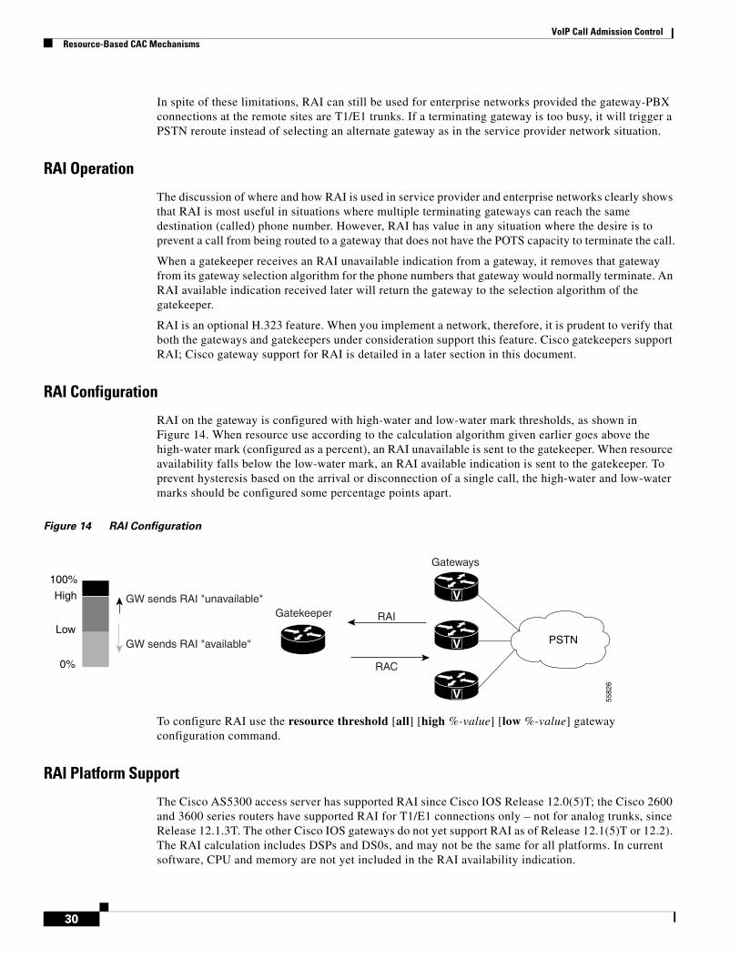
RAI Configuration
RAI on the gateway is configured with high-water and low-water mark thresholds, as shown in Figure 14. When resource use according to the calculation algorithm given earlier goes above the high-water mark (configured as a percent), an RAI unavailable is sent to the gatekeeper. When resource availability falls below the low-water mark, an RAI available indication is sent to the gatekeeper. To prevent hysteresis based on the arrival or disconnection of a single call, the high-water and low-water marks should be configured some percentage points apart.
Figure 14 RAI Configuration
To configure RAI use the resource threshold [all] [high %-value] [low %-value] gateway configuration command.
RAI Platform Support
The Cisco AS5300 access server has supported RAI since Cisco IOS Release 12.0(5)T; the Cisco 2600 and 3600 series routers have supported RAI for T1/E1 connections only – not for analog trunks, since Release 12.1.3T. The other Cisco IOS gateways do not yet support RAI as of Release 12.1(5)T or 12.2). The RAI calculation includes DSPs and DS0s, and may not be the same for all platforms. In current software, CPU and memory are not yet included in the RAI availability indication.
V
V
V 5582
6
PSTN
Gatekeeper
Gateways
100%
0%
High
Low
GW sends RAI "unavailable"
GW sends RAI "available"
RAI
RAC
30
VoIP Call Admission ControlResource-Based CAC Mechanisms
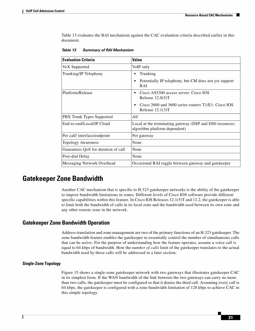
Table 13 evaluates the RAI mechanism against the CAC evaluation criteria described earlier in this document.
Gatekeeper Zone BandwidthAnother CAC mechanism that is specific to H.323 gatekeeper networks is the ability of the gatekeeper to impose bandwidth limitations in zones. Different levels of Cisco IOS software provide different specific capabilities within this feature. In Cisco IOS Releases 12.1(5)T and 12.2, the gatekeeper is able to limit both the bandwidth of calls in its local zone and the bandwidth used between its own zone and any other remote zone in the network.
Gatekeeper Zone Bandwidth Operation
Address translation and zone management are two of the primary functions of an H.323 gatekeeper. The zone bandwidth feature enables the gatekeeper to essentially control the number of simultaneous calls that can be active. For the purpose of understanding how the feature operates, assume a voice call is equal to 64 kbps of bandwidth. How the number of calls limit of the gatekeeper translates to the actual bandwidth used by those calls will be addressed in a later section.
Single-Zone Topology
Figure 15 shows a single-zone gatekeeper network with two gateways that illustrates gatekeeper CAC in its simplest form. If the WAN bandwidth of the link between the two gateways can carry no more than two calls, the gatekeeper must be configured so that it denies the third call. Assuming every call is 64 kbps, the gatekeeper is configured with a zone bandwidth limitation of 128 kbps to achieve CAC in this simple topology.
Table 13 Summary of RAI Mechanism
Evaluation Criteria Value
VoX Supported VoIP only
Trunking/IP Telephony • Trunking
• Potentially IP telephony, but CM does not yet support RAI
Platform/Release • Cisco AS5300 access server: Cisco IOS Release 12.0(5)T
• Cisco 2600 and 3600 series routers T1/E1: Cisco IOS Release 12.1(3)T
PBX Trunk Types Supported All
End-to-end/Local/IP Cloud Local at the terminating gateway (DSP and DS0 resources; algorithm platform dependent)
Per call/ interface/endpoint Per gateway
Topology Awareness None
Guarantees QoS for duration of call None
Post-dial Delay None
Messaging Network Overhead Occasional RAI toggle between gateway and gatekeeper
31

VoIP Call Admission ControlResource-Based CAC Mechanisms
Figure 15 Simple Single-Zone Topology
Most networks, however, are not as simple as the one shown in Figure 15. Figure 16 shows a more complex topology, but it is still configured as a single-zone network. In this topology, the legs in the WAN cloud each have separate bandwidth provisioning and therefore separate capabilities of how many voice calls can be carried across that leg. The numbers on the WAN legs in Figure 16 show the maximum number of calls that can be carried across that leg.
Figure 16 Complex Single-Zone Topology
Consider now that the gatekeeper zone bandwidth is still set to a maximum of 128 kbps, thus allowing no more than two simultaneous calls. This is the desired behavior of the network if both calls involve Site 1—the gatekeeper will protect the bandwidth of the WAN link from Site 1 to the WAN aggregation point by not allowing more than two calls across that link. But if both calls are within the Headquarters site, there is no reason to allow only two calls because there is plenty bandwidth in the campus backbone.
V V
PBX PBX
WANCall #2
Call #3 denied
Call #1
5582
7
GK
= H.323 RAS signaling
V
V V
V
PBX PBXWAN
PBX PBX
5582
8
GK
Zone bandwidth: 128kbps does not work anymore
Remote Site 1
Remote Site 2
Headquarters20
2
4
any
32
VoIP Call Admission ControlResource-Based CAC Mechanisms
Multizone Topology
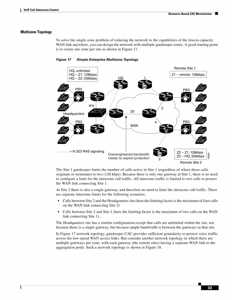
To solve the single-zone problem of reducing the network to the capabilities of the lowest-capacity WAN link anywhere, you can design the network with multiple gatekeeper zones. A good starting point is to create one zone per site as shown in Figure 17.
Figure 17 Simple Enterprise Multizone Topology
The Site 1 gatekeeper limits the number of calls active in Site 1 (regardless of where those calls originate or terminate) to two (128 kbps). Because there is only one gateway at Site 1, there is no need to configure a limit for the intrazone call traffic. All interzone traffic is limited to two calls to protect the WAN link connecting Site 1.
At Site 2 there is also a single gateway, and therefore no need to limit the intrazone call traffic. There are separate interzone limits for the following scenarios:
• Calls between Site 2 and the Headquarters site (here the limiting factor is the maximum of four calls on the WAN link connecting Site 2)
• Calls between Site 2 and Site 1 (here the limiting factor is the maximum of two calls on the WAN link connecting Site 1).
The Headquarters site has a similar configuration except that calls are unlimited within the site, not because there is a single gateway, but because ample bandwidth is between the gateways at that site.
In Figure 17 network topology, gatekeeper CAC provides sufficient granularity to protect voice traffic across the low-speed WAN access links. But consider another network topology in which there are multiple gateways per zone, with each gateway (the remote sites) having a separate WAN link to the aggregation point. Such a network topology is shown in Figure 18.
V
V V
PBX PBXWAN
PBX PBX
5582
9
GK GK
Remote Site 1
Remote Site 2
Headquarters20
2
4
any
HQ 1
2
V
GK= H.323 RAS signaling
HQ: unlimitedHQ – Z1: 128kbpsHQ – Z2: 256kbps
Z1 – remote: 128kbps
Z2 – Z1: 128kbpsZ2 – HQ: 256kbpsOverengineered bandwidth:
needs no explicit protection
33

VoIP Call Admission ControlResource-Based CAC Mechanisms
Figure 18 Complex Enterprise Multizone Topology
Of the three gateways in remote Site 1, the lowest WAN access link can carry a maximum of two simultaneous calls. Because the bandwidth limitation is configured per zone and not per gateway, there is no facility within gatekeeper CAC to limit the calls to specific gateways within the zone. Your best choice, therefore, is to configure the network for the lowest common denominator link: for both remote Sites 1 and 2, the lowest common denominator link is 128 kbps bandwidth or two calls.
This configuration will ensure proper voice quality at all times, but it is also wasteful of the gateways that could terminate more calls without oversubscribing their WAN bandwidth. In this network configuration, CAC will be activated too soon and will deflect certain calls over to the PSTN when in fact they could have been carried by the WAN. So in this type of topology, gatekeeper CAC is not sufficient to protect voice quality over the WAN link and also optimize the bandwidth use of all WAN links.
The last configuration to consider is a service provider network where the gateways in the POPs are connected via Fast Ethernet to the WAN edge router, which is shown in Figure 19.
V
V
V
V
V
WAN
V
V
V
V
GK
GK
GK
Remote Site 1
Remote Site 2
Headquarters
20
24
4
6
6
any
2
2
10
5
HQ
1
2
HQ: unlimitedHQ – Z1: 128kbpsHQ – Z2: 256kbps
Z1 – remote: 128kbps
Z2 – Z1: 128kbpsZ2 – HQ: 256kbps
5583
0
34
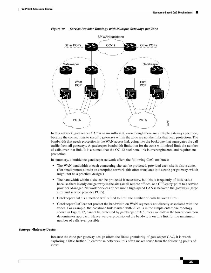
VoIP Call Admission ControlResource-Based CAC Mechanisms
Figure 19 Service Provider Topology with Multiple Gateways per Zone
In this network, gatekeeper CAC is again sufficient, even though there are multiple gateways per zone, because the connections to specific gateways within the zone are not the links that need protection. The bandwidth that needs protection is the WAN access link going into the backbone that aggregates the call traffic from all gateways. A gatekeeper bandwidth limitation for the zone will indeed limit the number of calls over that link. It is assumed that the OC-12 backbone link is overengineered and requires no protection.
In summary, a multizone gatekeeper network offers the following CAC attributes:
• The WAN bandwidth at each connecting site can be protected, provided each site is also a zone. (For small remote sites in an enterprise network, this often translates into a zone per gateway, which might not be a practical design.)
• The bandwidth within a site can be protected if necessary, but this is frequently of little value because there is only one gateway in the site (small remote offices, or a CPE entry-point to a service provider Managed Network Service) or because a high-speed LAN is between the gateways (large sites and service provider POPs).
• Gatekeeper CAC is a method well suited to limit the number of calls between sites.
• Gatekeeper CAC cannot protect the bandwidth on WAN segments not directly associated with the zones. For example, the backbone link marked with 20 calls in the simple enterprise topology shown in Figure 17, cannot be protected by gatekeeper CAC unless we follow the lowest common denominator approach. Hence we overprovisioned the bandwidth on this link for the maximum number of calls ever possible.
Zone-per-Gateway Design
Because the zone-per-gateway design offers the finest granularity of gatekeeper CAC, it is worth exploring a little further. In enterprise networks, this often makes sense from the following points of view:
VV
VV
VV
V
VV
V
Other POPs Other POPsOC-12
Gatekeeper Gatekeeper
SP WAN backbone
WestPOP
PSTN PSTN
EastPOP
6001
3
35

VoIP Call Admission ControlResource-Based CAC Mechanisms
• Geographical considerations.
• CAC to protect the WAN access link into a site containing a single gateway.
• Dialing plans often coincide with sites, so a zone prefix easily translates to the gateway serving that site if the gateway is equivalent to a zone.
A gatekeeper is a logical concept, not a physical concept. Each gatekeeper therefore does not mean a separate box in the network; it merely means a separate “local zone” statement in the configuration.
Where combined gateway and gatekeeper software images are available (as of Cisco IOS Release 12.1(5)T and Release 12.2), each gateway—at small remote sites in particular—can also be its own gatekeeper provided the CPU of that platform is sufficient for all these functions. (It likely also serves as the WAN edge router.)
A zone-per-gateway design nevertheless thwarts the scalability aspect that gatekeepers bring to H.323 networks, and largely negates the “centralized dialing plan” aspect of gatekeeper networks unless the dialing plan is implemented entirely on a separate level using directory gatekeepers. You should therefore carefully consider the advantages and limitations of such a design.
Gatekeeper in Call Manager Networks
Of all the CAC mechanisms discussed in this document, gatekeeper zone bandwidth is the only method applicable to multisite distributed Call Manager networks. In this scenario, the Call Manager behaves like a VoIP gateway to the H.323 gatekeeper, as is shown in Figure 20.
Figure 20 Gatekeeper in a Call Manager Topology
Cisco IOSgatekeeper
I am registering asa VoIP GW (RRQ)
Yes you can (ACF)No you cannot (ARJ)
Zone 1 Zone 2
PSTN
Callplaced PhiladelphiaSan Jose
36003600
x1111 x2111
WAN
6001
4
IP IP
May I make a call? (ARQ)H.323 RAS signalingCall flow
CallmanagerCallmanager
36
VoIP Call Admission ControlResource-Based CAC Mechanisms
Zone Bandwidth Calculation
The gatekeeper does not have any knowledge of network topology and does not know how much bandwidth is available for calls. Nor does the gatekeeper know how much of the configured bandwidth on the links is currently used by other traffic. The gatekeeper takes a fixed amount of bandwidth, statically configured on the gatekeeper as was shown in the preceding network examples, then subtract a certain amount of bandwidth for each call that is set up. Bandwidth is returned to the pool when a call is disconnected. If a request for a new call causes the remaining bandwidth to become less than zero, the call is denied. The gatekeeper therefore does not do bandwidth reservation of any kind; it merely does a static calculation to decide whether a new call should be allowed.
It is the responsibility of the gateways to inform the gatekeeper of how much bandwidth is required for a call. Video gateways therefore could request a different bandwidth for every call setup: one video session may require 256 kbps, another 384 kbps. Voice gateways should consider codec, Layer 2 encapsulation, and compression features (such as cRTP) when requesting bandwidth from the gatekeeper. Sometimes these features are not known at the time of call setup, in which case a bandwidth change request can be issued to the gatekeeper after call setup to adjust the amount of bandwidth used by the call. Currently, Cisco has not yet implemented this functionality.
The previous examples have assumed a fixed bandwidth of 64 kbps per call, which is how Cisco H.323 gateways are implemented in current software. The codec and other bandwidth-determining features such as cRTP are not currently considered when bandwidth of a call is considered by the gatekeeper zone bandwidth calculation. This will change in future software releases, but until then, implementing this feature requires a manual mathematical calculation of how many calls should be allowed based on n times 64 kbps per call and the total available WAN bandwidth.
Gatekeeper zone bandwidth nevertheless remains an inexact science because the gateway may not have full knowledge of the bandwidth required by the call. Layer 2 technologies used in the WAN or backbone legs of the network, and hop-by-hop features such as cRTP, may be used deeper into the network than the gateway is aware of. Following are some examples:
• The gateway may be attached to an Ethernet segment in a campus network where cRTP does not apply and where the Layer 2 headers are larger than they would be for Frame Relay or MLP on the WAN legs.
• A different codec may be used in the campus network from the WAN segments, leveraging codec transcoding functionality at the WAN edge.
• In the backbone of the network, ATM may be used as the transport technology and cell fill should be taken into account for bandwidth calculations.
• cRTP may be used at the WAN edge router.
Both the gateway and the gatekeeper are unaware of the network topology information described unless the gateway is also the WAN edge router, in which case the gateway/edge router has slightly more visibility. But it probably still will not see an ATM backbone and therefore will not account for it.
Zone Bandwidth Configuration
As of Cisco IOS Release 12.1(5)T and Release 12.2, the following types of zone bandwidth limitations can be configured on the gatekeeper:
• The maximum bandwidth for all H.323 traffic between the local zone and a specified remote zone. (If desired, this configuration can be repeated individually for each remote zone.)
• The maximum bandwidth allowed for a single session in the local zone (typically used for video applications, not for voice).
• The maximum bandwidth for all H.323 traffic allowed collectively to all remote zones.
37

VoIP Call Admission ControlResource-Based CAC Mechanisms
To configure gatekeeper zone bandwidth, use the following commands:
• bandwidth {interzone | total | session} {default | zone zone-name} max-bandwidth
• bandwidth remote max-bandwidth
Gatekeeper Zone Bandwidth Summary
Gatekeeper CAC works well in network designs where the desire is to limit the number of calls between sites. This may be required due to either bandwidth limitations or business policy. If bandwidth limitations are on the WAN legs, manual calculations can be done to translate the maximum number of calls to be allowed between sites into a bandwidth figure that will cause the gatekeeper to deny calls exceeding that number.
Gatekeeper zone bandwidth control is a key part of H.323 video network designs. Here bandwidth is more of an issue because video uses much more bandwidth per session than voice. In addition, different video sessions can request different amounts of bandwidth for video transmissions, making the manual calculation method used for voice almost unusable.
One additional thing to remember when designing gatekeeper CAC is that redundant gatekeepers complicate the issues somewhat. For example, if HSRP is used on the gatekeepers for redundancy, there is no shared database between the gatekeepers. If the primary gatekeeper fails, the secondary gatekeeper can take over, but it has no knowledge of how much bandwidth is currently used in the zone or how many calls are currently active. Until its information converges back to reflect reality, the secondary gatekeeper will allow too many calls onto the network. If alternate gatekeepers are used as the redundancy method, this problem is circumvented.
A major advantage of gatekeeper CAC is that it is the only CAC method that can incorporate mixed networks of Cisco IOS gateways and Call Managers with IP phones.
Table 14 evaluates the gatekeeper zone bandwidth mechanism against the CAC evaluation criteria described earlier in this document.
Table 14 Summary of GateKeeper Zone Bandwidth Mechanism
Evaluation Criteria Value
VoX Supported VoIP/H.323 only
Trunking/IP Telephony • Trunking and IP telephony
• Some caveats if both the Call Manager and Cisco IOS gateways used in the same zone
Platform/Release • Cisco IOS gateways since Release 11.3
• CM has recent changes in E.164 registration, and bandwidth requested per call.
PBX Trunk Types Supported All
End-to-end/Local/IP Cloud End-to-end between outgoing gateway and terminating gateway, although not aware of the network topology (bandwidth availability) in between
Per call/ interface/endpoint Per call
Topology Awareness None
Guarantees QoS for duration of call None
38
VoIP Call Admission ControlResource-Based CAC Mechanisms
Resource Reservation ProtocolRSVP is the only CAC mechanism that makes a bandwidth reservation and does not make a call admission decision based on a “best guess look-ahead” before the call is set up. This gives RSVP the unique advantage of not only providing CAC for voice, but also guaranteeing the QoS against changing network conditions for the duration of the call.
RSVP Feature Rollout
RSVP is synchronized with the H.323 state machine in Cisco IOS Release 12.1(5)T, and is therefore available in Release 12.2. Various components of this feature appeared in earlier releases of software, but it was not until 12.1(5)T that all the elements for CAC became available. Following is a short summary of RSVP support:
• RSVP synchronized with H.323 Standard Connect: Release 12.1(1)T
• RSVP support for LLQ: Release 12.1(3)T
• RSVP sync with H.323 FastConnect: Release 12.1(5)T
• RSVP support for FR PVCs: Release 12.1(5)T
RSVP support for ATM PVCs and RSVP support on the IP phones is being planned for future software releases.
RSVP Reservation for a Voice Call
Figure 21 shows a call flow of the H.323 call setup messages and the RSVP reservation messages.
Post-dial Delay None
Messaging Network Overhead Part of the gatekeeper RAS messaging
Table 14 Summary of GateKeeper Zone Bandwidth Mechanism
Evaluation Criteria Value
39

VoIP Call Admission ControlResource-Based CAC Mechanisms
Figure 21 RSVP Call Setup for H.323 Voice Call
The H.323 setup is suspended before the destination phone, triggered by the H.225 Alerting message, starts ringing. The RSVP reservation is made in both directions because a voice call requires a two-way speech path and therefore bandwidth in both directions. The terminating gateway ultimately makes the CAC decision based on whether both reservations succeed. At that point the H.323 state machine continues either with an H.225 Alerting/Connect (the call is allowed and proceeds), or with an H.225 Reject/Release (call is denied). The RSVP reservation is in place by the time the destination phone starts ringing and the caller hears ringback.
RSVP has the following important differences from other CAC methods discussed in this document:
• The ability to maintain QoS for the duration of the call.
• Awareness of topology. In concept, the RSVP reservation is installed on every interface the call will traverse through the network (we will discuss exceptions to this in later sections), and therefore will ensure bandwidth over every segment without needing to know the actual bandwidth provisioning on an interface, nor the path on which the routing protocols will direct the packets. (RSVP therefore adjusts automatically to network configuration changes, and no manual calculations are necessary to keep different aspects of the configuration synchronized.)
RSVP is an end-to-end reservation per call and only has visibility for that call. It is unaware of how many other calls are active from a site or across an interface, or the source or destination of any other call. Therefore, there is no way to configure aggregate levels of CAC with RSVP, such as the site-to-site CAC we could do with gatekeeper zone bandwidth control.
Classification for Voice Packets into LLQ
LLQ is one of the important Cisco QoS mechanisms to ensure quality for voice because it prioritizes voice packets over data packets at the router egress interface. For this to work, voice packets must be classified such that they are placed in the priority queue (PQ) portion of LLQ. Traditionally this is accomplished with Access Control List (ACL) classification, where the TCP (signaling) and UDP (media) ports are matched to funnel voice packets into the appropriate queues.
H.225 FastStart Setup (OGW UDP ports)H.323 Fast Connect Setup includes UDP port
RSVP modification
The TGW initiates thefirst PATH message
Alerting/Connect not setuntil a Resv Confirm isreceived
H.225 Call Proceeding (TGW UDP ports)
H.225 Alerting or Connect
RSVP path
RSVP Resv
RSVP Resv
RSVP ResvConf
RSVP path
Originating gateway (OGW) Terminating gateway (TGW)
5583
2
40

VoIP Call Admission ControlResource-Based CAC Mechanisms
As a general Cisco IOS feature, RSVP has its own set of reserved queues within weighted fair queueing (WFQ) for traffic with RSVP reservations. These queues, though they have a low weight, are separate from the PQ. Packets in reserved queues do not get priority over packets from other queues other than by virtue of their low weight. It has long been known that this treatment (a low weight queue inside WFQ) is insufficient for voice quality over a congested interface with several different flows of traffic. Therefore, when RSVP is configured for a voice call, the voice packets need to be classified into the PQ. RSVP data flow packets should not be classified into the PQ in this case.
RSVP uses a profile to determine whether a flow of packets is a voice flow. The profile considers packet sizes and arrival rates and other parameters, and a packet flow conforming to the parameters is considered a voice flow. If not, it is considered a nonvoice flow, including both data and video. The internal profile is tuned so that all voice traffic originating from a Cisco IOS gateway will fall within the parameters and will therefore be considered a voice flow without needing extra configuration. For third-party applications such as NetMeeting, the profile may need to be tuned to pick up that kind of traffic. Figure 22 shows how this is accomplished.
Figure 22 RSVP Packet Classification Criteria
RSVP is the first egress interface classifier to examine an arriving packet. If RSVP considers the packet a voice flow, the packets will be put into the PQ portion of LLQ. If the flow does not conform to the voice profile, but is nevertheless an RSVP reserved flow, it will be placed into the normal RSVP reserved queues. If the flow is neither a voice flow nor a data RSVP flow, the other egress interface classifiers (such as ACLs and “match” statements within a class-map) will attempt to classify the packet for queueing.
It is important to note that RSVP will classify only voice bearer traffic, not signaling traffic. One of the other classification mechanisms such as ACLs or DSCPs must still be used to classify the voice signaling traffic if any treatment better than Best-effort is desired for that traffic. If the decision is left up to RSVP alone, signaling traffic will be considered Best-effort traffic as shown in Figure 22.
Bandwidth Allocation with RSVP and LLQ
RSVP voice traffic can be mixed with “priority class” traffic (within the policy map) in the PQ, but the configuration is simpler if a single voice classification mechanism is used. We therefore recommend that you use one or the other for voice, but not both: Either configure RSVP to prioritize voice traffic,
RSVPClassification
PQ
Reservedqueues
Class 1
Class 2
Default/BE
Egress Interface/PVCQueueing (LLQ)
Unclassifiedflows
Voice conforming, admitted flows
Nonvoice conforming, admitted flows
non-admitted flows,voice signaling traffic,
path and Resv messages
5583
3
41
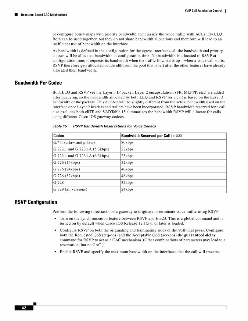
VoIP Call Admission ControlResource-Based CAC Mechanisms
or configure policy maps with priority bandwidth and classify the voice traffic with ACLs into LLQ. Both can be used together, but they do not share bandwidth allocations and therefore will lead to an inefficient use of bandwidth on the interface.
As bandwidth is defined in the configuration for the egress interfaces, all the bandwidth and priority classes will be allocated bandwidth at configuration time. No bandwidth is allocated to RSVP at configuration time; it requests its bandwidth when the traffic flow starts up—when a voice call starts. RSVP therefore gets allocated bandwidth from the pool that is left after the other features have already allocated their bandwidth.
Bandwidth Per Codec
Both LLQ and RSVP see the Layer 3 IP packet. Layer 2 encapsulations (FR, MLPPP, etc.) are added after queueing, so the bandwidth allocated by both LLQ and RSVP for a call is based on the Layer 3 bandwidth of the packets. This number will be slightly different from the actual bandwidth used on the interface once Layer 2 headers and trailers have been incorporated. RSVP bandwidth reserved for a call also excludes both cRTP and VADTable 15 summarizes the bandwidth RSVP will allocate for calls using different Cisco IOS gateway codecs.
RSVP Configuration
Perform the following three tasks on a gateway to originate or terminate voice traffic using RSVP:
• Turn on the synchronization feature between RSVP and H.323. This is a global command and is turned on by default when Cisco IOS Release 12.1(5)T or later is loaded.
• Configure RSVP on both the originating and terminating sides of the VoIP dial peers. Configure both the Requested QoS (req-qos) and the Acceptable QoS (acc-qos) the guaranteed-delay command for RSVP to act as a CAC mechanism. (Other combinations of parameters may lead to a reservation, but no CAC.)
• Enable RSVP and specify the maximum bandwidth on the interfaces that the call will traverse.
Table 15 RSVP Bandwidth Reservations for Voice Codecs
Codec Bandwidth Reserved per Call in LLQ
G.711 (a-law and μ-law) 80kbps
G.723.1 and G.723.1A (5.3kbps) 22kbps
G.723.1 and G.723.1A (6.3kbps) 23kbps
G.726 (16kbps) 32kbps
G.726 (24kbps) 40kbps
G.726 (32kbps) 48kbps
G.728 32kbps
G.729 (all versions) 24kbps
42

VoIP Call Admission ControlResource-Based CAC Mechanisms
The following configuration example enables RSVP:
!Global command enabling RSVP as CAC, turned on by default.call rsvp-synccontroller T1 1/0 ds0-group 0 timeslots 1-24!!RSVP classification profile; default is “ok” for all Cisco IOS gateway voice traffic.ip rsvp pq-profile voice-like!voice-port 1/0:0! dial-peer voice 100 pots destination-pattern 2...... port 1/0:0! dial-peer voice 300 voip destination-pattern 3...... session target ipv4:10.10.2.2!Configures RSVP CAC for voice calls using the dial peer. req-qos guaranteed-delay acc-qos guaranteed-delay
The following configuration example enables RSVP on a PPP interface:
interface Serial0/1 bandwidth 1536 ip address 10.10.1.1 255.255.255.0 encapsulation ppp!Enables WFQ as the basic queueing method. Results in LLQ with RSVP. fair-queue 64 256 36!Enables RSVP on the interface. ip rsvp bandwidth 1152 24
The following configuration example enables RSVP for a Frame Relay interface:
interface Serial0/0 bandwidth 1536 encapsulation frame-relay no fair-queue frame-relay traffic-shaping! interface Serial0/0.2 point-to-point ip address 10.10.2.2 255.255.255.0 frame-relay interface-dlci 17 class VoIPoFR!Enables RSVP on the subinterface.ip rsvp bandwidth 64 24map-class frame-relay VoIPoFR no frame-relay adaptive-shaping frame-relay cir 128000 frame-relay bc 1280 frame-relay mincir 128000!Enables WFQ as the basic queueing method. Results in LLQ with RSVP. frame-relay fair-queue frame-relay fragment 160
RSVP Scalability
Concern is often expressed about RSVP scalability in terms of the large number of individual flow reservations that may be necessary across high-speed backbone links where many voice calls have aggregated. Indeed it may not make sense to do individual flow management over OC-12 backbone
43
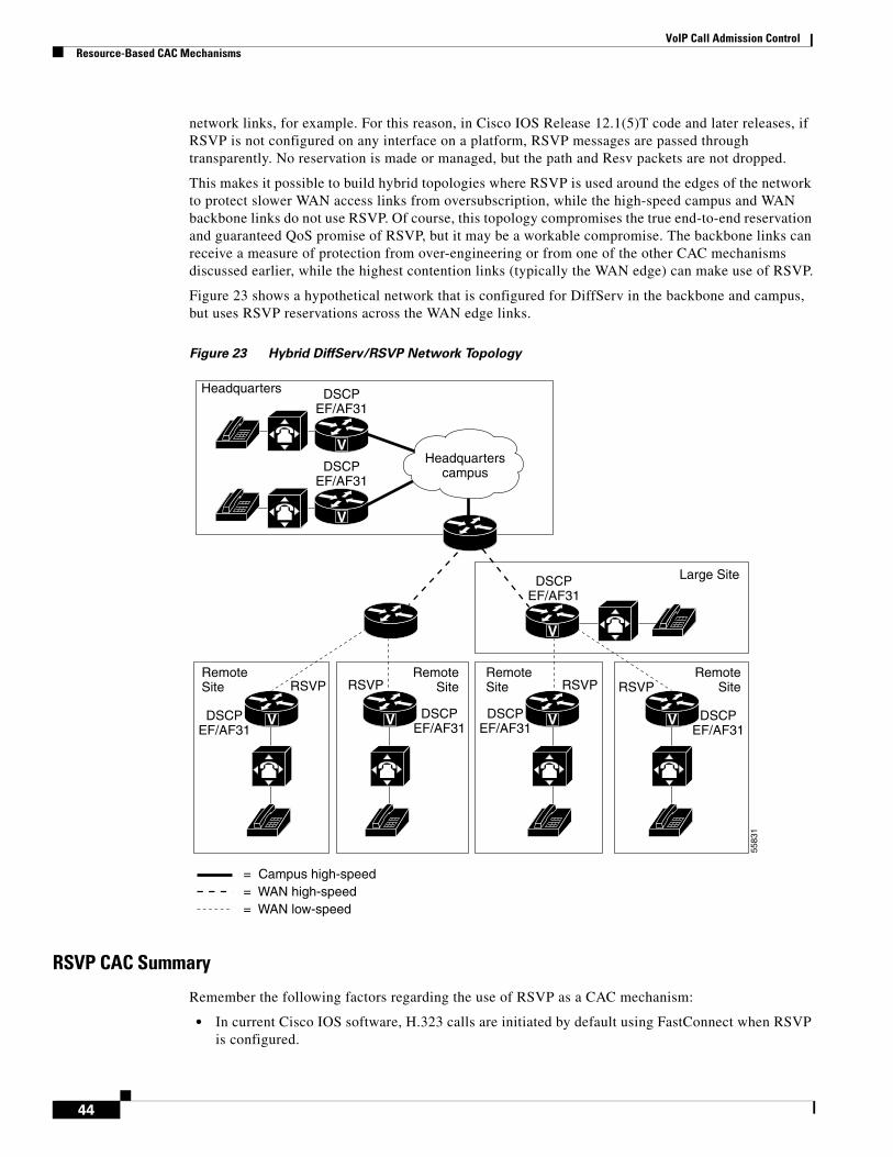
VoIP Call Admission ControlResource-Based CAC Mechanisms
network links, for example. For this reason, in Cisco IOS Release 12.1(5)T code and later releases, if RSVP is not configured on any interface on a platform, RSVP messages are passed through transparently. No reservation is made or managed, but the path and Resv packets are not dropped.
This makes it possible to build hybrid topologies where RSVP is used around the edges of the network to protect slower WAN access links from oversubscription, while the high-speed campus and WAN backbone links do not use RSVP. Of course, this topology compromises the true end-to-end reservation and guaranteed QoS promise of RSVP, but it may be a workable compromise. The backbone links can receive a measure of protection from over-engineering or from one of the other CAC mechanisms discussed earlier, while the highest contention links (typically the WAN edge) can make use of RSVP.
Figure 23 shows a hypothetical network that is configured for DiffServ in the backbone and campus, but uses RSVP reservations across the WAN edge links.
Figure 23 Hybrid DiffServ/RSVP Network Topology
RSVP CAC Summary
Remember the following factors regarding the use of RSVP as a CAC mechanism:
• In current Cisco IOS software, H.323 calls are initiated by default using FastConnect when RSVP is configured.
V
V
Headquarters
Large Site
RemoteSite
RemoteSite
RemoteSite
RemoteSite
DSCPEF/AF31
DSCPEF/AF31
DSCPEF/AF31
DSCPEF/AF31
DSCPEF/AF31
DSCPEF/AF31
DSCPEF/AF31
V
V VVV
= Campus high-speed= WAN high-speed= WAN low-speed
5583
1
Headquarterscampus
RSVPRSVPRSVP RSVP
44

VoIP Call Admission ControlHow to Apply CAC to Your Network
• RSVP packets (PATH and RESV) travel as best-effort traffic.
• WFQ must be enabled on an interface/PVC as a basis for LLQ.
RSVP is a true end-to-end CAC mechanism only if configured on every interface that a call traverses.
For the unique ability to serve as both an end-to-end CAC mechanisms, and to guarantee the QoS for the entire duration of the call, RSVP does incur some “costs” on the network, as follows:
• Signaling (messaging and processing)
• Per flow state (memory)
• Postdial delays
• RSVP does not provide for call redirection after call setup if a link in the network should fail
• RSVP is not yet supported on the Cisco IP phones
Table 16 evaluates the RSVP mechanism against the CAC evaluation criteria described earlier in this document.
How to Apply CAC to Your NetworkAlthough there is some overlap between the functionality the different CAC mechanisms provide, there are also several of these that solve different aspects of the CAC problem and therefore would make sense to use together in a network design. The following questions often arise:
• Can two CAC methods be used together on the same gateway at the same time for the same calls?
• (If the answer to the preceding question is yes) In what sequence is the CAC decision reached?
Figure 24 summarizes the sequencing of CAC features that can be active on an outgoing gateway, based on Cisco IOS Release 12.1(5)T and 12.2. As features and software releases change, and as bugs are fixed, this information may change without notice. As the flow diagram shows, the only features that are mutually exclusive are RSVP and PSTN fallback.
Table 16 Summary of RSVP Mechanism
Evaluation Criteria Value
VoX Supported VoIP/H.323 only
Trunking/IP Telephony Currently trunking only
Platform/Release Cisco IOS gateways in Release 12.1(5)T and 12.2
PBX Trunk Types Supported All
End-to-end/Local/IP Cloud • End-to-end between outgoing gateway and terminating gatekeeper (provided all intermediate nodes are RSVP configured)
• Could be used at WAN edge with DiffServ backbone
Per call/ interface/endpoint Per call
Topology Awareness Yes
Guarantees QoS for duration of call Yes
Post-dial Delay Yes
Messaging Network Overhead PATH/RESV and periodic keepalives
45

VoIP Call Admission ControlHow to Apply CAC to Your Network
Figure 24 Sequence of CAC Feature Utilization on an Outgoing Gateway
The following sections describes how you can deploy the CAC mechanisms:
• When and Which CAC Mechanism to Use
• CAC in Connection Trunk Networks
• Areas of the Network to Protect
• Network Topology Considerations
When and Which CAC Mechanism to UseWith a plethora of CAC mechanisms available, the immediate design question is, “When should I use which CAC feature?” As has been noted during the discussions of the individual features, and through the comparisons and summaries that have been drawn throughout the text, the various features often do different things and solve different aspects of a CAC problem. Some of these aspects may be more important design criteria for your network than others. Thus, there is no single recipe prescribing exactly when to use which mechanism. As with all other software features, you must make the decision while considering your network design goals.
This section attempts to provide some guidance concerning design criteria that might exist for your network, and if so, which features might fit the solution. The feature selection criteria that should be used first are the “Evaluation Criteria” listed at the end of each feature section previously described. For example, if a SIP-based VoIP network is being designed, there is no point in considering an H.323 CAC feature. Provided you have already accomplished that level of screening, use the suggestions in this section to further narrow the choice of features.
Localresources
CACconfiguration?
CAC pass?
Proceedwith callsetup
Rejectcall
RSVP CACconfiguration?
PSTN fallback CACconfiguration?
Gatekeeper bandwidth Managementconfiguration?
CAC pass?
CAC pass?
CAC pass?
N
N
N
N
N
N
N
N
Y
Y
Y
Y
Y Y
YY
5583
4
46
VoIP Call Admission ControlHow to Apply CAC to Your Network
CAC in Connection Trunk NetworksUnlike in switched networks, where each call is set up individually across the packet network after a user dials, “connection trunk” networks consist of nailed-up connections across the packet network. The PBX may perceive that it makes each call individually, but the packet network has a permanent trunk in place (a point-to-point link, similar in concept to a leased line) that is always present, always ready, and always terminates to a fixed and predetermined destination. These nailed-up packet network configurations are typically used when some signaling is present between the PBXs that must pass transparently and unchanged through the packet network. The gateways cannot interpret the signaling; they merely tunnel it through the packet network.
There are two major applications for this type of network as follows:
• Networks in which signaling such as flash-hook and Message Waiting Indications (MWI) must be passed through the packet network to a PBX to be activated for Off Premise Extension (OPX) phones—phones that are separated by the packet network from the PBX from which they draw their features.
• Networks in which proprietary signaling is used between PBXs to enable private PBX networking features. (Examples include Lucent DCS, Siemens CorNet, and NEC CCIS.)
Cisco IOS gateway connection trunk configurations use the same basic tools (such as dial peers) as switched networks to set up connections. The difference is that these “calls” are set up only once, when the gateway boots up or when the configuration is inserted, and remain in place indefinitely. If a link in the network should fail and bring the call down, the router will reestablish it at its earliest opportunity. Whether there is actually a real call active (with people talking) over this connection is transparent to the gateways. For this reason, the standard CAC mechanisms, in most cases, do not apply. Connection trunk configurations will not come up properly if there is not enough bandwidth for the connection, so once the configuration is in place, sufficient bandwidth should be available for the calls.
The following call-by-call CAC mechanisms apply only to switched networks and should not be used with connection trunk configurations:
• Max-Connections
• PSTN Fallback
• Resource Availability Indication
• Gatekeeper Zone Bandwidth
Connection trunk configurations can, however, benefit from the PBX busyout CAC features. When something in the network is down and the permanent connections fail, or the interfaces they use fail, it would certainly be useful to busy out the trunk to the PBX. These features are the following:
• Trunk Conditioning
• Local Voice Busyout
• Advanced Voice Busyout
In concept, RSVP could be used to guarantee (reserve) bandwidth for the nailed-up calls in order to protect the voice quality from fluctuating network conditions. However, because connection trunk networks are fixed, point-to-point connections, the number of calls active across any network segment (from the perspective of the router) is fixed and relatively easily designed by manually engineering the bandwidth and by using standard LLQ configurations to ensure bandwidth. You should carefully consider if RSVP will be useful in such a situation.
47

VoIP Call Admission ControlHow to Apply CAC to Your Network
Areas of the Network to ProtectCAC methods are most useful and most needed in switched networks where it is often impossible to predict exactly how many calls might want to use a particular network leg at a given time. Statistical methods for engineering voice networks have existed for decades; nevertheless, there is no mechanism by which to know exactly who will call whom across the network at any given time. Unless the topology of the network is very simple, bandwidth at some point in the network may be oversubscribed by too many calls. In the PSTN this condition results in reorder tone or an intercept message indicating “all circuits are busy.”
When considering CAC methods to trigger a comparable “all circuits are busy” condition when a packet network is too congested to carry a call, also consider the goals of the network design. All the aspects of CAC shown in Figure 25 exist in every network, but some attributes will almost always be more important to a particular customer than others. The aspects of the network that may need protection with CAC features have been divided into four areas (A, B, C, and D), as shown in Figure 25.
Figure 25 Division of Areas of the Network
Area A is the originating POTS connection. If it is important to keep the originating PBX from attempting to place a call onto the packet network when the network is incapable of completing the call, then the busyout CAC features should be considered. This may be important if hairpinning is an unacceptable call reject recovery method, or if the PBX/Key system does not have the ability to choose another route for a rejected or hairpinned call.
Area B is the terminating POTS side of the connection. If it is likely because of specific traffic patterns that the terminating POTS side is the part of network most susceptible to oversubscription, then gatekeeper RAI should be used. In enterprise networks this is seldom of overarching importance, but in service provider networks this is often an extremely important section of the network to protect.
Area C is the IP backbone part of the network. This is the most typical area of the packet network that enterprise customers (including Service Provider Managed Services networks) want to protect their calls against, because this infrastructure is not dedicated to voice, but is shared by many types of traffic. The CAC features protecting the network “cloud” are the following:
• PSTN Fallback
• Gatekeeper Zone Bandwidth
• Resource Reservation Protocol
V V
V
PBX
PBX
WAN PSTN
A
5583
5
B
C
D
48
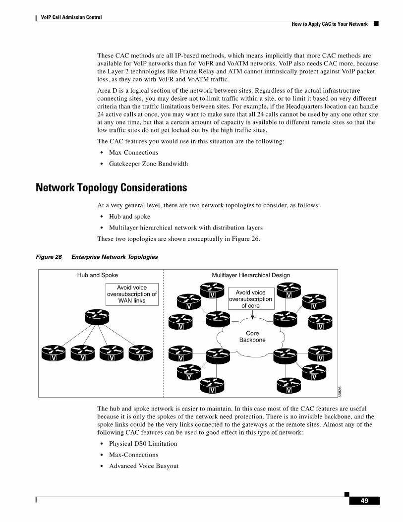
VoIP Call Admission ControlHow to Apply CAC to Your Network
These CAC methods are all IP-based methods, which means implicitly that more CAC methods are available for VoIP networks than for VoFR and VoATM networks. VoIP also needs CAC more, because the Layer 2 technologies like Frame Relay and ATM cannot intrinsically protect against VoIP packet loss, as they can with VoFR and VoATM traffic.
Area D is a logical section of the network between sites. Regardless of the actual infrastructure connecting sites, you may desire not to limit traffic within a site, or to limit it based on very different criteria than the traffic limitations between sites. For example, if the Headquarters location can handle 24 active calls at once, you may want to make sure that all 24 calls cannot be used by any one other site at any one time, but that a certain amount of capacity is available to different remote sites so that the low traffic sites do not get locked out by the high traffic sites.
The CAC features you would use in this situation are the following:
• Max-Connections
• Gatekeeper Zone Bandwidth
Network Topology ConsiderationsAt a very general level, there are two network topologies to consider, as follows:
• Hub and spoke
• Multilayer hierarchical network with distribution layers
These two topologies are shown conceptually in Figure 26.
Figure 26 Enterprise Network Topologies
The hub and spoke network is easier to maintain. In this case most of the CAC features are useful because it is only the spokes of the network need protection. There is no invisible backbone, and the spoke links could be the very links connected to the gateways at the remote sites. Almost any of the following CAC features can be used to good effect in this type of network:
• Physical DS0 Limitation
• Max-Connections
• Advanced Voice Busyout
V V V V
V
V
V
V
V
V
V
V
V
V
V
V
CoreBackbone
Hub and Spoke Mulitlayer Hierarchical Design
Avoid voiceoversubscription of
WAN linksAvoid voice
oversubscriptionof core
5583
6
49
VoIP Call Admission ControlHow to Apply CAC to Your Network
• PSTN Fallback
• Resource Availability Indication
• Gatekeeper Zone Bandwidth
• Resource Reservation Protocol
The multi-layer hierarchical network is more representative of larger networks where outlying sites aggregate at one or more layers of intermediate points before a core network that connects the highest layer aggregation sites. Many of the CAC features will protect the WAN link at the lowest layer of the network, but few of them have visibility into the aggregation and core legs of the network. The features that have visibility into the network are the following:
• Advanced Voice Busyout
• PSTN Fallback
• Resource Reservation Protocol
50