vo'.13 2 bug.- sept. 1967 -...
TRANSCRIPT

RCA ENGINEER Staff
W. O. Hadlock Editor
J. C. Phillips Assistant Editor
Mrs. D. R. McNulty Editorial Secretary
J. L. Parvin Art Director
Consulting Editors
C. A. Meyer, Technical Publications Administrator,
Electronic Components and Devices
C. W. Sall, Technical Publications Administrator, RCA Laboratories
G. Smaller, Technical Publications Administrator, Electronic Data Processing
F. D. Whitmore, Technical Publications Administrator, Communications Systems
Division
Editorial Advisory Board A. D. Beard, Chief Engineer
Electronic Data Processi
E. D. Becken, Vice President and Chief Engineer, RCA Communications, Inc.
J. J. Brant, Staff Vice President, Personnel Administration
C. C. Foster, Mgr., RCA REVIEW
M. G. Gander, Mgr., Consumer Product Administration, RCA Service Co.
Dr. A. M. Glover, Division Vice President Technical Programs,
Electronic Components and Devices
C. A. Gunther, Division Vice President, Technical Programs, DEP and EDP
E. C. Hughes, Administrator, Technical Committee Liaison,
Electronic Components and Devices
W. R. Isom, Chief Engineer, RCA Victor Record Division
E. O. Johnson, Mgr., Engineering, Technical Programs,
Electronic Components and Devices
G. A. Kiessling, Manager, Product Engineering Professional Development
L. R. Kirkwood, Chief Engineer, RCA Victor Home Instruments Division
W. C. Morrison, Director, Product Engineering
D. F. Schmif, Staff Vice President, Product Engineering
D. Shore, Chief Defense Engineer, DEP Defense Engineering
J. L. Wilson, Director, Engineering National Broadcasting Co., Inc.
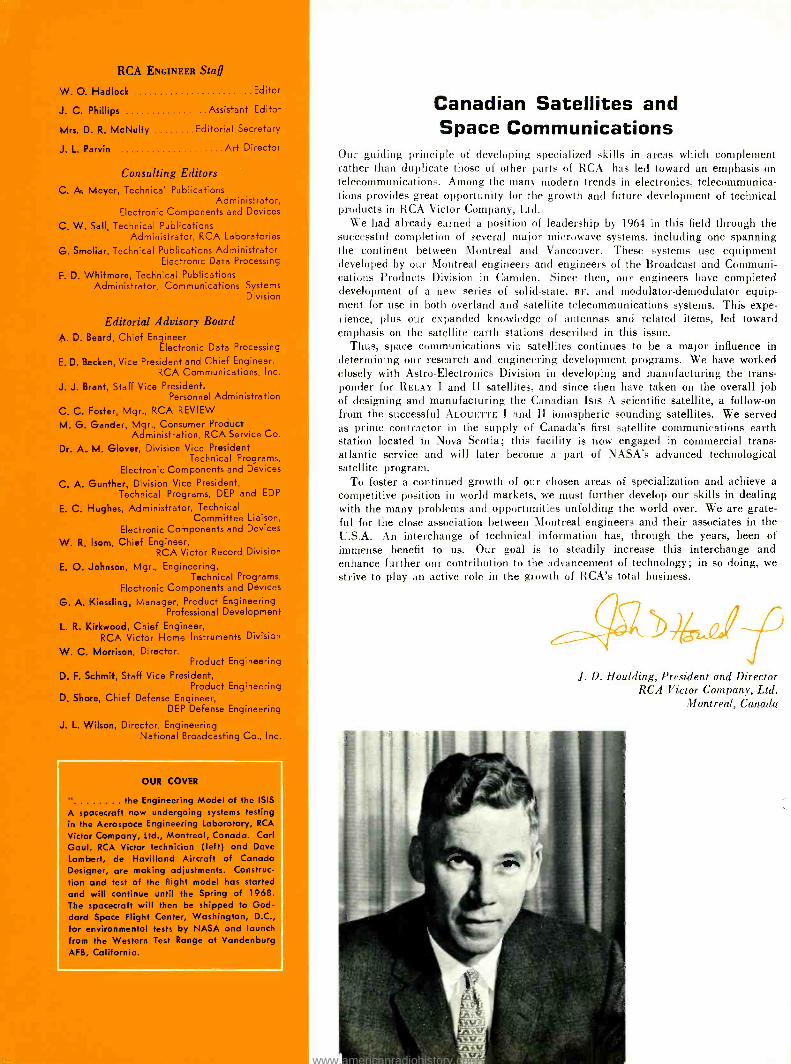
OUR COVER
the Engineering Model of the ISIS
A spacecraft now undergoing systems testing in the Aerospace Engineering Laboratory, RCA
Victor Company, Ltd., Montreal, Canada. Carl Gaul, RCA Victor technician (left) and Dave Lambert, de Havilland Aircraft of Canada Designer, are making adjustments. Construc- tion and test of the flight model has started and will continue until the Spring of 1968. The spacecraft will then be shipped to God- dard Space Flight Center, Washington, D.C., for environmental tests by NASA and launch from the Western Test Range at Vandenburg AFB, California.
Canadian Satellites and Space Communications
Our guiding principle of developing specialized skills in areas which complement rather than duplicate those of other parts of RCA has led toward an emphasis on telecommunications. Among the many modern trends in electronics, telecommunica- tions provides great opportunity for the growth and future development of technical products in RCA Victor Company, Ltd.
We had already earned a position of leadership by 1964 in this field through the successful completion of several major microwave systems, including one spanning the continent between Montreal and Vancouver. These systems use equipment developed by our Montreal engineers and engineers of the Broadcast and Communi- cations Products Division in Camden. Since then, our engineers have completed development of a new series of solid -state, Re, and modulator -demodulator equip- ment for use in both overland and satellite telecommunications systems. This expe- rience, plus our expanded knowledge of antennas and related items, led toward emphasis on the satellite earth stations described in this issue.
Thus, space communications via satellites continues to be a major influence in determining our research and engineering development programs. We have worked closely with Astro- Electronics Division in developing and manufacturing the trans- ponder for RELAY I and II satellites, and since then have taken on the overall job of designing and manufacturing the Canadian Isis A scientific satellite, a follow -on from the successful ALOUETTE I and II ionospheric sounding satellites. We served as prime contractor in the supply of Canada's first satellite communications earth station located in Nova Scotia; this facility is now engaged in commercial trans- atlantic service and will later become a part of NASA's advanced technological satellite program.
To foster a continued growth of our chosen areas of specialization and achieve a competitive position in world markets, we must further develop our skills in dealing with the many problems and opportunities unfolding the world over. We are grate- ful for the close association between Montreal engineers and their associates in the U.S.A. An interchange of technical information has, through the years, been of immense benefit to us. Our goal is to steadily increase this interchange and enhance further our contribution to the advancement of technology; in so doing, we strive to play an active role in the growth of RCA's total business.
J. D. Houlding, President and Director RCA Victor Company, Ltd.
Montreal, Canada
www.americanradiohistory.com

RC A NGINEER
VOL. 13, NO. 2
AUG. -SEP., 1967
CONTENTS
To Staff an Industry -A Discussion of the Engineer's Role in Electronics
Current Concepts in Science and Engineering -An Engineering Project in Continuing Education
Space Activity in Canada
System Design and Reliability Considerations for the ISIS A Spacecraft
Command, Telemetry, and Tracking System for the ISIS A Spacecraft L A. Keyes, P.T. Caden, J. Zuran 17
Dr. G. H. Brown 2
J. W. Wentworth 5
J A. Collins, G. B. MacKimmie 10
L A. Keyes, Dr. W. R. Atkins 12
Thermal Design of the ISIS A Spacecraft G G. Gray 22
Laboratory Studies of Satellite Design Problems ....F. J. F. Osborne, M. A. Kasha 26
Electrical and Mechanical Design of the Mill Village Antenna -Radome Complex
Cost Considerations in Designing Earth Stations
P Foldes, I. Scott 30
P Foldes 35
ce The Wideband Communications System of Canada's
á Mill Village Communications Satellite Earth Station J. A. Stovman 40
d
W F o z
Multipath Effects in Space Communications H Staras 45
A Tribute to an Engineer's Engineer 48
Technical Books by RCA Engineers 50
The Two -Pound Radar U. A. Frank, D. L. Kratzer, J. L. Sullivan 52
An Approach to Radiation Effects in MOS Devices Dr. A. G. Holmes -Siedle, Dr. K. H. Zaininger 55
Computer Design -Some Pitfalls to Avoid G Smoliar 60
TV Applications of MOS Transistors W. M. Austin, J. A. Dean, D. M. Griswold, O. P. Hart 63
Keeping Score in Space - USAF Spacetrack H F. Duncan, J. J. Duncan, H. R. Headley 70
Two -Polarization FM Broadcasting with a Single Antenna . . Dr. M. S. Siukola 74
A Computer Program for Analyzing Alternative Maintenance Policies W. A. Triplett 77
An Advanced Technique for Video Data Compression W. T. Bisignani, G. P. Richards 81
Dollars Versus Protection in Destructive Testing D S Wright 86
Mechanized Reffow Soldering of Flatpack Integrated Circuits J. W. Kaufman 87
Pen and Podium -A Subject- Author Index to RCA Technical Papers... 89
Patents Granted 92
Engineering News and Highlights 93
A TECHNICAL JOURNAL PUBLISHED BY RADIO CORPORATION OF AMERICA, PRODUCT ENGINEERING 2 -8, CAMDEN, N. J.
To disseminate to RCA engineers technical information of professional value. To publish in an appropriate manner
important technical developments at RCA, and the role of the engineer. To serve as a medium of interchange of technical
information between various groups at RCA. To create a community of engineering interest within the company by stressing
the interrelated nature of all technical contributions. To help publicize engineering achievements in a manner that will
promote the interests and reputation of RCA in the engineering field. To provide a convenient means by which the RCA
engineer may review his professional work before associates and engineering management. To announce outstanding and
unusual achievements of RCA engineers in a manner most likely to enhance their prestige and professional status. Copyright 1967
Radio Corporation of America v
All Rights Reserved
RCA ENGINEER articles are indexed annually In the April -May Issue and in the "Index to RCA Technical Papero"
www.americanradiohistory.com

Editor's Note: The success of a technically oriented indus- try such as electronics depends strongly on the role of the engineer -his transition from college to industry, his de- gree of involvement, and his continued professional devel- opment. These are some of the factors discussed by Dr.
Brown in a talk ( "Staffing An Industry ") given in May 1967,
before the Congress of Canadian Engineers, Montreal. His complete speech is published here.
TO STAFF AN INDUSTRY
-A Discussion of the Engineer's Role in Electronics
DR. GEORGE H. BROWN
Executive Vice President Research and Engineering
Radio Corporation of America Princeton, New Jersey
ISHOULD preface my remarks today by stating that I am unable to write a reliable prescription to cure the problems
relating to staffing a technically based industry. Rather, I shall confine myself to some observations derived from my over thirty years experience in the electronics industry. While I shall no doubt neglect the problems relating to many of the varied roles of engineers in our society today, I do this not from lack of appreciation of the importance of civil or mining engineering but from an awareness of the shallow knowledge I possess in these areas.
ELECTRONICS: COMPLEX, ALIVE, AND DYNAMIC
Few are the industries that today can continue a famous prod- uct unchanged and unimproved, though some patent- medicine makers seem to do so. With the possible exception of the chemical industry, none can surpass the electronics industry for change as a way of life. Electronics pervades all aspects of our modern society. The electronics industry has at least two roles. One is that fulfilled by the manufacture and sale of products which go directly to the private citizen, that is to say, the class of products known as "home instruments," the radio, the television set, or the record player. The other is that
2
fulfilled by the manufacture of products or devices which furnish the techniques used in other major industries. Ex- amples are the automotive and aircraft industries, the chemical and pharmaceutical industries, the broadcasting and commu- nications companies. There are so many different facets to electronics that no one company, however large, can, embrace them all.
An industry so alive and dynamic is made up of a complex of companies varying in size and degrees of specialization. There are some very large companies, a much larger number of intermediate size, and thousands of very small ones filling many ecological niches in the general economy.
START SMALL AND GROW ON MERIT
Before approaching the topic of staffing, we might consider the evolution of a typical company even though we know very well that there is no really typical company. The big companies grew to greatness by starting small, winning public confidence with timely quality products, and expanding with increased demands for the products. Earnings were reinvested in expan- sion of facilities and work force, including engineers. Some companies grew by acquisition and consolidation of a number of small companies or by mergers of larger entities. But each element had to start small and grow on merit.
As a small company grows, its products depend more and more on engineering concepts and inventions. This develops the need not only for more engineers but also for more kinds of engineers. It also requires more kinds of nontechnical people. A new business built around the knowledge of a small group, who may have migrated from a large company, soon has to have assistance of mechanical and chemical engineers and, eventually, of plant and facilities engineers. There will probably grow a need for the design of special production machinery. As production increases, so will the requirements for factory production engineers, packaging engineers, mate- rials and process engineers increase. As the entrepreneurs use up their initial store of knowledge that gave rise to the initial successes, they will have to undertake new developments and a measure of research.
COMPETITION AND INNOVATION
A well -balanced concern must keep its corporate eyes on com- petition and costs, while developing a technical organization with a scale of reasonable salaries from that of the new engi- neering graduate to that of a chief engineer. Some of the original working engineers may now become leaders of a group, with progressions to management of even larger groups. Up to a point, the chief engineering manager or executive can be personally acquainted with every person in his group or even his company. Eventually this becomes impractical if not im- possible, at least for the top executives.
By the time a company has progressed that far, something has generally happened to the whole industry to exert external pressures. To have been successful means that a company has gradually adjusted to changes -the impact of market evolution or competitive pressures. A really viable company has also produced its own impact on others through innovations and imaginative concepts adapted to real needs of users. But often the opposite may happen. The original people may run out of their store of knowledge and are unable to keep the pace. If they are too specialized, the need for their product may vanish.
www.americanradiohistory.com

They can sometimes revitalize and reorient their staff by hiring engineers with skills and knowledge more in tune with the times. They may diversify their work so that they can sustain the demise of certain products while prospering with others. If the technical and economic management has been good, the company may increase rapidly in size, big enough to buy smaller ones that round out its needs or to merge with another.
So in most industries, particularly in the electronics industry, there are great numbers of companies at all stages of growth, from the new ambitious beginners to the venerable giants em- ploying thousands of engineers of many disciplines.
TRANSITION FROM COLLEGE TO INDUSTRY
Now let us look at the individual engineer in industry. What is his life? Certainly if he has exhibited the discipline, the en- durance and the devotion to complete a sound engineering course in a university, he comes to industry with enthusiasm and ambition. A wise management will not expect too much of him for a year or two as he adjusts to the strange new demands of industrial duties. He will study diligently and have the inspiration of exposure to experienced men. He mas- ters one small area of work and learns how it fits into the work of others. He endures the drudgery of solving sticky problems and enjoys the elation of surmounting them. In time, he be- comes recognized in his company, and perhaps outside of it, as an expert in some aspect of technology. Unless he settles down to be a technical provincial who is satisfied with higher and higher degrees of specialization, he will expand his inter- ests and take every opportunity and responsibility to extend his fields of expertness, but taking care not to be too superficial.
CONTINUED GROWTH
With continued growth and advancement, he may become leader of a group or a large project team. As he approaches manager status he must become accustomed to the difference between working with things or with people, and begin to realize the change that comes now with working with men and ideas and money. He must console himself with the realization that he cannot keep up technically with all his men, that it is deadly to try to compete with them, but yet he must maintain his technical growth in order to comprehend what goes on, to appraise alternatives, and to judge fairly his men's competence. He must also represent his men before higher management. Of course, his responsibility has increased many fold at this stage and many hard decisions have to be faced. He is con- stantly faced with the task of evaluating ideas, results, and people.
PERSONAL PROFESSIONAL DEVELOPMENT
A universal characteristic of any engineering career in modern Ì industry is one's role as a member of a team of workers whose
collective effort and skills come together to achieve results unachievable by a galaxy of individual stars. As an industrial employee and particularly as a team member, the industrial engineer never appears to the general public as a professional man. He does not appear before the public in the same way as an architect, a physician, or even a consulting engineer. Yet he is a professional man and is so recognized by his asso- ciates and in the professional societies. Most companies today have very liberal publication policies which enable engineers to publish much valuable proprietary information which brings
r
DR. GEORGE H. BROWN studied at the University of Wisconsin, receiving his BSEE in 1930, his MS in
1931, and his PhD in 1933. In 1962, the University of Wisconsin awarded a Distinguished Service Citation to Dr. Brown for his leadership in industry and engi- neering. In 1933, Dr. Brown joined the RCA Manu-
facturing Co. in Camden, N.J., as a research engineer. In 1942 he transferred to the new RCA Laboratories research center at Princeton, N.J. During World War II, Dr. Brown was responsible for important advances in antenna development for military systems, and for the development of radio - frequency heating techniques. He and his associ-
ates also developed a method for speeding the production of penicillin. At the end of the war, Dr. Brown received a War Department Certificate of Appreciation for his outstanding work in the research, design, and development of radio and radar antennas during World War II." From 1948
to 1957, Dr. Brown played a leading part in the direction of RCA's research and development of color and UHF television systems. In 1952, he was appointed Director, Systems Research Laboratory, RCA Laboratories. In 1957, he was appointed Chief Engineer, RCA Commercial Electronic Products Division, Camden, and six months later, Chief Engi- neer, RCA Industrial Electronic Products. In 1959,
he was appointed Vice President, Engineering, Radio Corporation of America, and became Vice President, Research and Engineering, in 1961. He was appointed to his present position in 1965. That same year he was elected to the Board of Directors of RCA. A prolific inventor, Dr. Brown holds 79
U.S. patents; he is included in American Men of Science. Dr. Brown is a Fellow of the IEEE and the American Association for the Advancement of Sci- ence, and a member of Sigma Xi, the Franklin Institute, and the National Academy of Engineer- ing. He is a Registered Professional Engineer of the State of New Jersey.
www.americanradiohistory.com

the engineer into prominence nationally and often internation- ally. Most companies allow time for their engineers to attend professional meetings and to participate in professional affairs and events, often at substantial cost. This is part of his con- tinued education and development which ought, in the long run, to be a satisfactory investment.
Any company that has prospered in business for several years has a corps of older engineers, usually near the top of the salary scale, who have avoided managerial duties or have failed to be selected. Such men represent a lot of valuable experience; they know how to do things; they can coach and encourage younger men; and they can otherwise do an undis- tinguished but valuable job. Many may never have published a technical paper, quite satisfied to work along year after year in a certain anonymity professionally. Some keep up their technology and some do not. One of the most demanding tasks of engineering management is to recognize the young dead wood as potential old dead wood and to do something about it before time runs out.
Industrial engineers usually have access to excellent com- pany libraries that make relevant periodical and book literature available to those who try to maintain their professional com- petence or as reference material for their work. A wise man- ager will encourage his engineers to use library time as a means of continued personal development.
A CHALLENGE TO ENGINEERING MANAGERS
A major problem in large organizations is that of keeping top engineering managers up -to -date technically. The rapidity with which electronic technology advances makes it very diffi- cult to even comprehend new technology without working directly in it. Yet decisions, appraisals, allocations of men and money to various activities under one's jurisdiction depend upon some knowledge of today's science and technology. The use of mathematics today in what we can call ordinary engi- neering is orders of magnitude greater than it was twenty years ago. Branches of mathematics are in common use today that were not taught to engineering students at that time. The engineer today depends more on computation than on labora- tory tests. Years ago, the engineering laboratories had the immense machinery while the physicists worked on benches in corners. This has all changed and it is the physicists who have the immense machines while the electrical engineer needs less and less as his skill in computation increases. Digital- computers are his newer tools, augmenting the traditional slide rule.
NEED FOR CONTINUING EDUCATION
Almost every company has lectures and discussions that help engineers to keep abreast of special subjects. In the Radio Corporation of America, we are trying systematically to en- hance the knowledge of engineering managers. It is often called a "retread" course, but its name is "Current Concepts in Science and Engineering." It is run as a formal school in business hours, led by selected university professors and RCA teachers. The course encompasses a total of 24 class days, extending over a period of ten months. Textbooks are supplied and homework assignments are given. Each class averages about fifty students. After an experimental period with a pilot class in 1964, it was extended to several locations because our plants are widely distributed. In this way, we believe our key engineering managers can better comprehend the rapidly changing foundations of our varied and technically oriented businesses. The spontaneous expressions of approval by those who have completed the courses indicates that our efforts were not in vain. In fact, the response to this program has led us to make plans to extend these teaching techniques in a somewhat different form to our graduate engineers who are not in the management ranks:
4
Because of our corporate interest in continuing education, we thought it appropriate to consult the patient concerning his prior exposure to the educational bug. As part of my corporate research and engineering staff activities, we publish a small monthly magazine called TREND (The Research and Engineer- ing News Digest). Several months ago, we used TREND as a vehicle to ask our engineers what they thought of engineering education. Essays were solicited to answer the question "Are colleges doing a good job of educating engineers ?" The answers were varied but interesting. About two out of three engineers felt that colleges are not doing a good job of edu- cating engineers. One of the most frequently stated reasons for this feeling was the lack of well- rounded training. A num- ber of responses said that engineering schools were not putting enough emphasis on the humanities, social sciences, and liberal arts. Several writers discussed the conflict between specialized and basic training. Many felt that it was the industry's respon- sibility to provide the specialized training after the engineer had learned his fundamentals in the colleges. Several sug- gested that the undergraduate training should be extended to five years.
ENGINEERS CAN AND DO COMMUNICATE Through all the responses ran the charges that engineers are not taught to communicate, that is, to speak and to write. Many engineering schools do have courses aimed at resolving these defects. I have often heard categorical statements to the effect that engineers do not know how to write. I only agree with this flat statement to the extent that I also believe most other people do not know how to write. But I also believe that for those people who can be taught to write the teaching must be done in the grade schools or high school. If this is not done, it is too late. In reviewing the essays, I was interested to observe that those who complained because the engineering schools were not teaching engineers to write and to express themselves voiced their complaints in very readable and some- times elegant prose.
I have read innumerable papers and reports during my pro- fessional career, efforts of engineers and of other people, and I agree with my fellow engineers that the English language suf- fers at the hands of hosts of people. But I have here with me today a piece of writing by an eminent engineer, Herbert Hoover, which I have treasured for years for its clarity of ex- pression, its pungency, and its thoughtfulness. It seems appro- priate to share his words with you.
"The great liability of the engineer com- pared to men of other professions is that his works are out in the open where all can see them. His acts, step by step, are in hard sub- stance. He cannot bury his mistakes in the grave like the doctors. He cannot argue them into thin air or blame the judges like the lawyers... . He cannot, like the poli- ticians, screen his shortcomings by blaming his opponents and hope that the people will forget. On the other hand, unlike the doctor, his is not a life among the weak. Unlike the soldier, destruction is not his purpose. Un- like the lawyer, quarrels are not his daily bread. To the engineer falls the job of cloth- ing the bare bones of science with life, corn - fort, and hope. No doubt as years go by, people forget which engineer did it, even if they ever knew.... But the engineer him- self looks back at the unending stream of goodness which flows from his successes with satisfactions that few professions may know."
1. J. Wentworth, "Current Concepts in Science and Engineering," this issue of the RCA ENGINEER.
www.americanradiohistory.com

CURRENT CONCEPTS IN SCIENCE AND ENGINEERING
An Engineering Project in Continuing Education
The great majority of the projects reported in the pages of the RCA ENGINEER relate to "hardware" developments undertaken as part of the company's efforts to serve its commercial or government customers. This article describes a
"software" project undertaken primarily to meet the professional -development needs of an important group within RCA itself. Current Concepts in Science and Engineering (CCSE) is a program of continuing education that has already served more than 400 RCA engineering managers and leaders. Development of this program has been one of RCA's major endeavors in the field of edu- cation; the final program embodies a number of unusual concepts and educa- tional techniques that should be of interest to all RCA engineering personnel.
JOHN W. WENTWORTH, Mgr. Engineering Educational Programs
Product Engineering, Camden, New Jersey
VERY few practicing engineers need to be reminded of the "knowledge
explosion" that has taken place in our profession since World War II. Even a casual reader of the RCA ENGINEER must be aware that many of the develop- ments described in recent issues of this journal are based on concepts that were virtually unknown as recently as ten years ago. The present pace of technical progress suggests that at least as many advances will be made during the com- ing decade as during the last. One by- product of this knowledge explosion in technology has been a recent upsurge of interest in continuing education for engi- neers and their managers. It has become almost self- evident that no engineer can hope to keep up with his pro- fession by applying only the knowledge he acquired while earning his bacca- laureate degree -he must continue to learn through experience and through participation in formal educational pro- grams or through self -guided study.
RCA, like most modern employers of engineers and scientists, has long recog- nized an obligation to participate in the professional development of its person- nel. The Corporation has played an active role in continuing education for many years through such activities as the Graduate Study Program, the Tuition Loan and Refund Plan, and the after - hours courses sponsored by the Com- pany at most of its engineering loca- tions. By 1963, however, the people most Final manuscript received June E3, 1967
directly concerned with professional de- velopment within RCA felt that the prob- lems of continuing education had in- tensified to the point where major new programs should be initiated to meet the growing needs. There was particular concern about educational opportunities in the technical area for engineering managers and leaders, who have special needs that were not being met by any of the existing programs.
In comparison with the engineers per- forming specialized tasks under his direction, the manager or leader needs technical knowledge characterized by breadth rather than depth. Conventional graduate -level courses, oriented to the needs of young people still working toward advanced degrees, are not well suited in either content or teaching methods to the needs of engineering management. The typical manager or leader has accumulated at least 10 years of experience since he left the university, and has become so preoccupied with ad- ministrative problems that he is hard - pressed for time to maintain his mathe- matical skills and to undertake purely technical studies. (Few managers have the time, for example, to work in a for- mal sense toward advanced degrees.) In spite of these handicaps, members of engineering management must devote a reasonable fraction of their time to the problem of keeping themselves up to date if they expect to retain their com- petence to direct technical programs.
The CCSE Program described in this
article was developed primarily to meet the specific needs of RCA engineering management, but it is also intended to serve as a "proving ground" for the de- velopment of techniques suitable for other professional -development pro- grams in the future.
BACKGROUND
The ccsE Program was conceived during 1963 through the combined efforts of professional -development specialists in Product Engineering and Corporate Staff Personnel. The author was appointed to direct the program in late 1963, and creation of the program was formally announced at a meeting of RCA chief engineers and other key engineering managers in November of that year. Representatives from each of RCA's major product divisions and operating units were invited to join a CCSE Plan- ning and Coordinating Committee, which met several times during the first six months of 1964 to plan the program's objectives, format, and curriculum. Meanwhile, a ccsE Program Staff was formed by the appointment of two well - qualified instructors to work with the author as course -development adminis- trators.
Because a number of new concepts were embodied in the initial plans for the ccsE Program, a decision was made to "field test" the program by operating a pilot class. With the help of the CCSE
Planning and Coordinating Committee, a class of 28 students was organized to begin the program in September, 1964. These students represented most of the major product divisions, and were care- fully selected to provide a range of age and experience that was reasonably typi- cal of RCA's total engineering manage- ment population. The pilot class met at the Ivystone Inn in Pennsauken, New Jersey, for two days every two weeks between September, 1964, and February, 1965 (a total of 12 two -day sessions).
A number of changes were made in the ccsE Program based on the pilot -run experience, and three regular classes (serving 140 participants) were initiated during the 1965 -1966 class year. Five additional classes with an enrollment of 240 students have been conducted dur- ing the 1966 -1967 class year.
PROGRAM OBJECTIVES
One of the first activities of the ccsE Planning and Coordinating Committee was to draw up a formal statement of program objectives:
Current Concepts in Science and Engi- neering is intended to support the RCA engineering manager or leader in his efforts to:
5
www.americanradiohistory.com
6
Update his technical knowledge. Recognize the major technical trends affecting RCA's business. Appreciate the significance of the major unifying concepts which are common to many scientific and engineering dis- ciplines. Acquire greater knowledge of RCA re- sources, and widen his circle of ac- quaintances within RCA engineering management. Develop knowledge of and confidence in new engineering methods, especially those based on the use of computers. Strengthen his personal reading and study habits.
NOTEWORTHY ASPECTS OF THE
CCSE PROGRAM
Educational programs with objectives similar to those of the CCSE Program have been established by several educa- tional institutions (notably UCLA and the Polytechnic Institute of Brooklyn) and by several other industrial corpora- tions. The CCSE Program differs from the other programs known to this writer in a number of important respects, how- ever. Unusual and significant features of the CCSE Program include:
Reliance on company resources. While some use is made of college professors and other outside specialists, most of the teach- ing and planning load for the CCSE Pro- gram has been carried by RCA personnel. (Many other companies rely on univer- sities to plan and operate continuing edu- cation programs of this magnitude.)
Development by engineers and scien- tists. The ccsE Program was developed not by people who had previously special- ized in training development but by pro- fessionally qualified engineers and scien- tists with personal competence in many of the subject areas included in the cur-
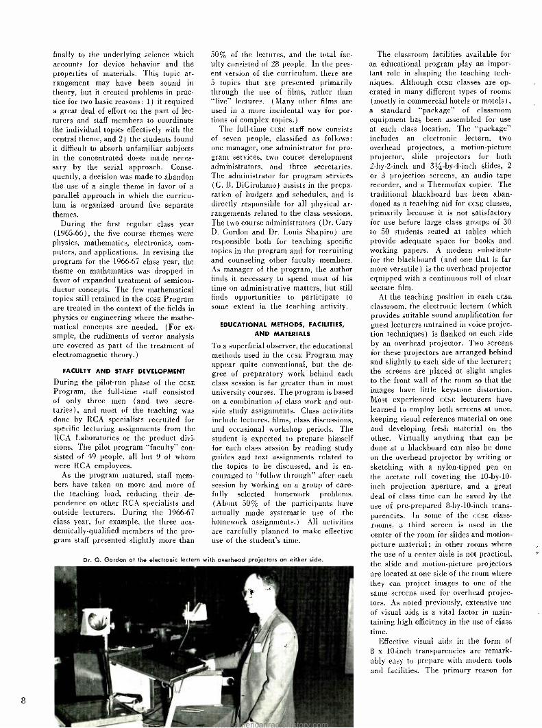
Informal lunch -time conversation helps managers
JOHN W. WENTWORTH was graduated from the
University of Maine with a BSEE degree in 1949, and
joined RCA in July of that year. After several years of development and design work on color television studio equipment, he became Manager of TV Termi- nal Equipment Engineering, a position he held 'rom 1953 to 1959. He then directed his attention to the field of educational technology, and served
several years as Manager of Educational Electronics for the Broadcast and Communications Products Division. Teaching, writing, and lecturing act:v: ties
were prominent throughout his career with the
Broadcast Division. He developed and taught after -hours courses in color television engineering that were attended by several hundred RCA and
NBC engineers; he authored numerous papers and
a complete textbook on color television engineer- ing; and he developed several courses for cus-
riculum. The procedures used for devel- oping the program were essentially the same as those used in carrying out engi- neering design projects.
Magnitude Related to Staff Size. Some of the well -publicized programs sponsored by other companies for the technical up- dating of their engineering managers have been designed to serve only one or two classes per year (perhaps 30 to 60 stu- dents). The CCSE Program has been de- signed to serve 240 participants at a time, even though the full -time staff consists of only four men and three secretaries.
Conservation of Student Time. The costs involved in operating the ccsE Pro- gram are distinctly different from those which apply to a conventional graduate school at a university. Because CCSE "stu- dents" are relatively senior people who have already advanced to management positions, salaries for time spent in attend- ing classes represent a major part of the CCSE Program costs. (Student salaries ex- ceed all other program expenses by a fac- tor of about two.) Efficiency in the use of student time has, therefore, been given a great deal of attention in developing the program. The degree of preparation ex- pected of lecturers is considerably greater than for typical university programs, and class schedules are arranged to minimize disruptive effects on the participants' normal work routines.
Visually-Oriented Teaching. As one means of maintaining high efficiency in the use of class time, great emphasis has been placed on the use of visual teaching aids, prepared in advance of the actual class sessions. The ccsE staff has devel- oped methods for producing such visual aids (notably transparencies for overhead projection) with only modest expenditures of time and money.
Feedback and Evaluation Techniques. The CCSE Program is dynamic in char- acter; significant changes have been made in the program year by year in response to feedback data obtained from the stu- dents through systematic evaluation pro- cedures.
and leaders to become better acquainted.
tomer training in television tape recording and
other aspects of broadcast technology. In early
1964, Mr. Wentworth was appointed Manager of the
Current Concepts in Science and Engineering' Program, an RCA staff activity aimed at supporting engineering managers and leaders in their efforts to stay abreast of new and fast -changing technolo- gies. His title was recently changed to that of Manager, Engineering Educational Programs in rec-
ognition of the fact that the scope of his position has been widened to embrace the development of
additional programs of continuing education for RCA engineering personnel. Mr. Wentworth is a
Fellow of the SMPTE, and holds memberships in
Tau Beta Pi, Phi Kappa Phi, the Society of the Sigma Xi, and the IEEE. He is a Registered Professional Engineer in New Jersey.
CHARACTERISTICS OF CCSE PARTICIPANTS
It has already been noted that partici- pants in the ccsE Program differ in a number of important respects from typical graduate students. Data ab- stracted from the registration forms for CCSE, Classes 1 through 8 (approxi- mately 400 participants) are summar- ized below:
Occupation at Time of Enrollment % of all Participants
Managers 52.5 Leaders 32.4 Others (mostly Staff Engineers) 15.1
Educational Background No Formal Degree Highest Degree: B.S.
M.S. Ph.D.
Years of Experience
Note:
4.4% 61.4% 30.0% 4.2%
since Baccalaureate Degree 10 or less 4.8% 11 -15 25.1% 16 -20 36.6% 21 -25 15.6% 26 -30 10.3% 30 -35 4.8% 36 or more 2.8%
Median age of ccsE participants to date is 39 years ; median number of years since first degree is 17.
A few comments may be in order about some of the more subjective aspects of the CCSE student population. The great majority of CCSE participants have aban- doned any interest they may once have had in working toward advanced de- grees, but the author has found them to be highly motivated students; they ap- pear to be eager to learn about new con- cepts in science and technology. (As a general rule, engineers who have ad- vanced into management ranks demon- strate high motivation for most tasks they undertake.) ccsE students are keenly aware of the value of their own time, and are generally under very great pressure to use this time efficiently. While technical concepts are important to the participant, he typically spends most of his time on non -technical prob- lems; he can spare time for the detailed study of new technical topics only if he anticipates some application of such topics to his work. With respect to
www.americanradiohistory.com

"`creature comforts" and classroom pro- cedures, the participant expects to be treated with reasonable deference to the professional status he has earned as an engineering manager or leader.
PROGRAM FORMAT
Participants are organized into classes that have ranged in size from 32 to 55 students. Each class meets for twelve 2 -day class sessions, which are held at 3 -week intervals throughout an aca- demic year. Five of the eight classes completed to date have been operated at the Cherry Hill Inn in Cherry Hill, New Jersey ; two have been located on
-4 the campus of Purdue University at West Lafayette, Indiana, and one was oper- ated at the Molly Pitcher Inn in Red Bank, New Jersey.
The decision to base the ccsE Program on a total of 24 class days was made as a "design choice" while the program was in an early planning stage. The decision has proved to be quite sound -the 24 days provide enough time for adequate treatment of a wide range of concepts, while the total time diverted by each student from his routine activities re- mains within reasonable limits.
The possibility of scheduling classes for periods of a week or more at a time was given serious consideration, but was rejected in favor of 2 -day class ses-
sions for the following reasons:
1) Managers can "break away" from normal business much more easily for 2 -day periods than for periods of a week or more.
2) There was a feeling that senior people with rusty study habits might reach a "saturation limit" on their learning curves after more than two days of intensive, fast -paced instruction.
3) Intervals of a few weeks between class sessions make possible the systematic use of reading assignments and other "homework" for the participants. De- liberate scheduling of the program over an academic year increases the total time that each student can reasonably be expected to invest in the program.
4) Intervals of a few weeks between class sessions also provide opportunities for the program staff to make revisions and adjustments in the program in response to the actual needs of the students as discovered during the early sessions.
It was originally planned to hold class meetings at monthly intervals, but ex- perience with the accelerated pilot class (based on class sessions at 2 -week inter- vals) indicated that 3 -week intervals would provide better retentivity between sessions while still providing adequate time for homework assignments. The use of 3 -week intervals makes it unneces- sary to schedule classes during the sum- mer vacation months, but still permits
simultaneous operation of as many as six classes by the limited ccsE Program staff. (Multiple class groups are scheduled on
a staggered basis, using both Monday - Tuesday and Thursday- Friday sessions.)
Although participants from the Cam- den- Moorestown area have been able to attend classes at the Cherry Hill Inn while living at home, approximately one - half of all ccsE students to date have found it necessary to travel moderate dis- tances and to remain overnight at the training center location during each class session. From an educational point of view the more distant students have found the inconvenience of travel more than compensated for by the benefits of greater isolation from the normal pres- sures of the office. Lunches for the class group on each meeting day are con- sidered an important part of the CCSE
Program. Participants are seated in groups of eight at small tables, and the informal lunch -time conversation helps the managers and leaders to become better acquainted with each other and to share information on topics of mutual interest.
CURRICULUM DEVELOPMENT
Subject matter for the GCSE Program is organized into five basic courses, which are conducted in parallel throughout the program. Titles for the five courses are: Modern Physics, Semiconductors, Elec- tronics Engineering, Computers and Their Utilization, and Applications and RCA Programs. One or two topics from at least four of these five courses are de- veloped during each session; students seem to welcome the changes in pace provided by moving from one subject area to another during a class day.
Modern Physics receives major em- phasis in the ccsE Program because it provides the foundation essential for understanding current and future devel- opments in materials and electronic de- vices. An objective of the physics course is to enable each manager or leader to "talk the same language" as the younger men who join RCA's engineering groups each year. The teaching of college phys- ics has changed significantly during the past fifteen years. Emphasis has shifted away from Newtonian mechanics and macroscopic phenomena toward quantum mechanics and phenomena at the atomic and subatomic levels. The senior tech- nical man has usually become familiar with some of the new concepts through reading and discussions with his col- leagues, but he lacks the thorough un- derstanding that comes from pursuing a well -organized course of study.
The semiconductors course provides greatly expanded treatment of one sub-
ject in modern physics that is of particu- lar importance to RCA engineers and scientists. Theoretical material on semi- conductor physics is supplemented by practical information on junction diodes, transistors, thyristors, tunnel diodes, in- jection lasers, and other semiconductor devices.
In the electronics engineering course, primary emphasis is placed on the newer techniques which have become important to RCA during the past decade or so. Digital computers are singled out for special attention because of the growing importance of the computer as an essen- tial engineering tool in all disciplines. Material is presented both on the funda- mentals of computer technology and on basic programming techniques. FORTRAN is taught by a workshop method; the participants actually write FORTRAN pro- grams (ranging in complexity from sim- ple tables up to procedures for solving differential equations) which are run off on a computer during the intervals be- tween class sessions.
The course on Applications and RCA Programs provides opportunities to pre- sent topics which illustrate practical applications of concepts presented else- where in the program, and also serves to acquaint the participants with major engineering programs currently in prog- ress throughout the Corporation. The present curriculum plan for the CCSE Program as described above is the product of an evolutionary process. For the pilot class, an attempt was made to arrange the subject matter around a single theme as a means of emphasizing the basic unity of modern science and technology. The theme selected was "Information Handling ", since almost every aspect of RCA's business is related in some way to the handling of infor- mation - its origination, acquisition, transduction, processing, recording, re- trieval, transmission, or reception. The basic curriculum plan for the pilot pro- gram is shown by the following outline of session titles.
1) Systems Principles; 2) Energy Conversion and Transducers; 3) Signal Handling (two sessions) ;
4) Information Storage and Transmis- sion ;
5) Components, Devices, and Materials; 6) Modern Physics (two sessions) ;
7) Contemporary Science; and 8) Tools and Techniques of Modern Engi-
neering (three sessions).
An objective of this plan was to sustain student interest by working progressively from systems concepts toward equip- ment and circuit concepts, thence to components, devices, and materials, and
7
www.americanradiohistory.com
8
finally to the underlying science which accounts for device behavior and the properties of materials. This topic ar- rangement may have been sound in theory, but it created problems in prac- tice for two basic reasons: 1) it required a great deal of effort on the part of lec- turers and staff members to coordinate the individual topics effectively with the central theme, and 2) the students found it difficult to absorb unfamiliar subjects in the concentrated doses made neces- sary by the serial approach. Conse- quently, a decision was made to abandon the use of a single theme in favor of a parallel approach in which the curricu- lum is organized around five separate themes.
During the first regular class year (1965 -66) , the five course themes were physics, mathematics, electronics, com- puters, and applications. In revising the program for the 1966 -67 class year, the theme on mathematics was dropped in favor of expanded treatment of semicon- ductor concepts. The few mathematical topics still retained in the CCSE Program are treated in the context of the fields in physics or engineering where the mathe- matical concepts are needed. (For ex- ample, the rudiments of vector analysis are covered as part of the treatment of electromagnetic theory.)
FACULTY AND STAFF DEVELOPMENT
During the pilot -run phase of the CCSE
Program, the full -time staff consisted of only three men (and two secre- taries), and most of the teaching was done by RCA specialists recruited for specific lecturing assignments from the RCA Laboratories or the product divi- sions. The pilot program "faculty" con- sisted of 49 people, all but 9 of whom were RCA employees.
As the program matured, staff mem- bers have taken on more and more of the teaching load, reducing their de- pendence on other RCA specialists and outside lecturers. During the 1966 -67 class year, for example, the three aca- demically- qualified members of the pro- gram staff presented slightly more than
50% of the lectures, and the total fac- ulty consisted of 28 people. In the pres- ent version of the curriculum, there are 5 topics that are presented primarily through the use of films, rather than "live" lectures. (Many other films are used in a more incidental way for por- tions of complex topics.)
The full -time CCSE staff now consists of seven people, classified as follows: one manager, one administrator for pro- gram services, two course development administrators, and three secretaries. The administrator for program services (G. B. DiGirolamo) assists in the prepa- ration of budgets and schedules, and is directly responsible for all physical ar- rangements related to the class sessions. The two course administrators (Dr. Gary D. Gordon and Dr. Louis Shapiro) are responsible both for teaching specific topics in the program and for recruiting and counseling other faculty members. As manager of the program, the author finds it necessary to spend most of his time on administrative matters, but still finds opportunities to participate to some extent in the teaching activity.
EDUCATIONAL METHODS, FACILITIES,
AND MATERIALS
To a superficial observer, the educational methods used in the CCSE Program may appear quite conventional, but the de- gree of preparatory work behind each class session is far greater than in most university courses. The program is based on a combination of class work and out- side study assignments. Class activities include lectures, films, class discussions, and occasional workshop periods. The student is expected to prepare himself for each class session by reading study guides and text assignments related to the topics to be discussed, and is en- couraged to "follow through" after each session by working on a group of care- fully selected homework problems. (About 50% of the participants have actually made systematic use of the homework assignments.) All activities are carefully planned to make effective use of the student's time.
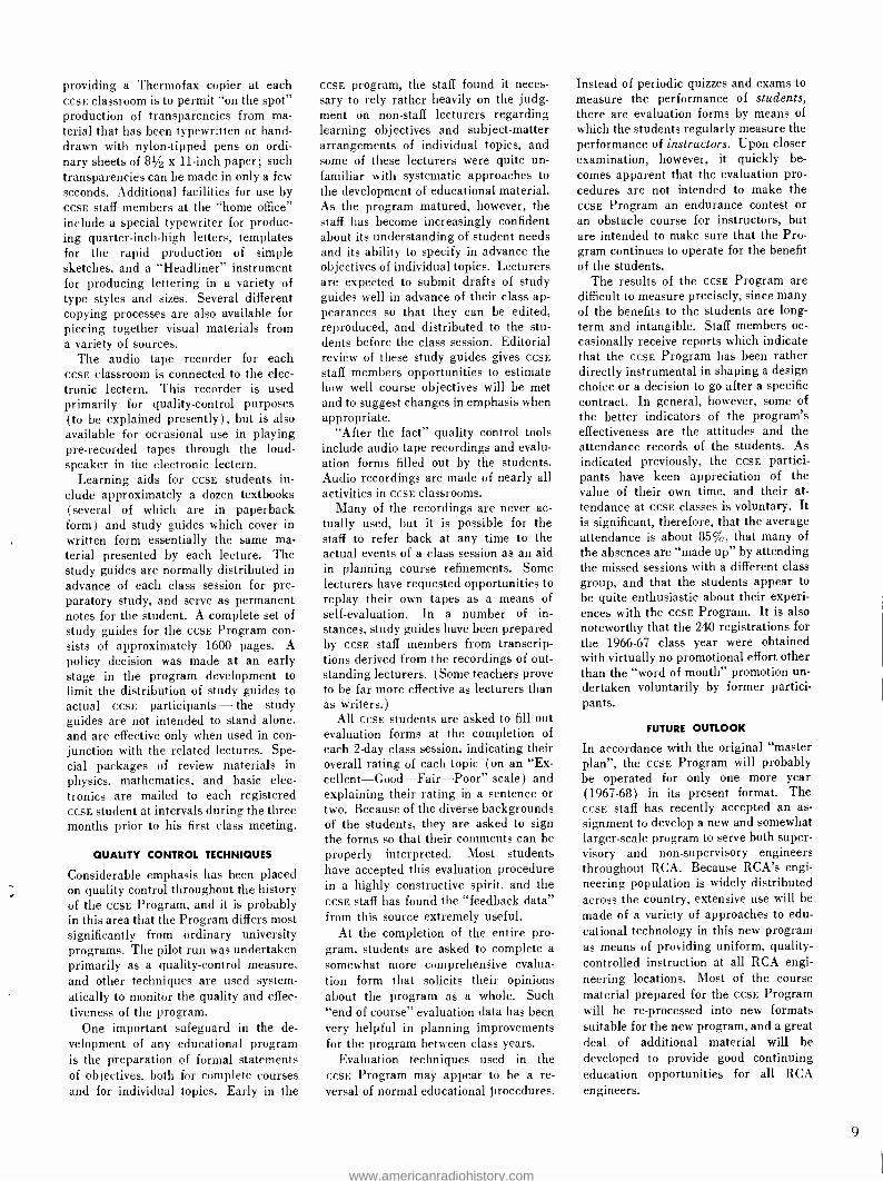
Dr. G. Gordon at the electronic lectern with overhead projectors on either side.
The classroom facilities available for an educational program play an impor- tant role in shaping the teaching tech- niques. Although CCSE classes are op- erated in many different types of rooms (mostly in commercial hotels or motels), a standard "package" of classroom equipment has been assembled for use at each class location. The "package" includes an electronic lectern, two overhead projectors, a motion -picture projector, slide projectors for both 2 -by -2 -inch and 31/4 -by4-inch slides, 2
or 3 projection screens, an audio tape recorder, and a Thermofax copier. The traditional blackboard has been aban- doned as a teaching aid for CCSE classes, primarily because it is not satisfactory for use before large class groups of 30 to 50 students seated at tables which provide adequate space for books and working papers. A modern substitute for the blackboard (and one that is far more versatile) is the overhead projector equipped with a continuous roll of clear acetate film.
At the teaching position in each CCSE
classroom, the electronic lectern (which provides suitable sound amplification for guest lecturers untrained in voice projec- tion techniques) is flanked on each side by an overhead projector. Two screens for these projectors are arranged behind and slightly to each side of the lecturer; the screens are placed at slight angles to the front wall of the room so that the images have little keystone distortion. Most experienced CCSE lecturers have learned to employ both screens at once, keeping visual reference material on one and developing fresh material on the other. Virtually anything that can be done at a blackboard can also be done on the overhead projector by writing or sketching with a nylon- tipped pen on the acetate roll covering the 10- by -10-
inch projection aperture, and a great deal of class time can be saved by the use of pre -prepared 8 -by -10 -inch trans- parencies. In some of the CCSE class- rooms, a third screen is used in the center of the room for slides and motion - picture material; in other rooms where the use of a center aisle is not practical, the slide and motion -picture projectors are located at one side of the room where they can project images to one of the same screens used for overhead projec- tors. As noted previously, extensive use of visual aids is a vital factor in main- taining high efficiency in the use of class time.
Effective visual aids in the form of 8 x 10 -inch transparencies are remark- ably easy to prepare with modern tools and facilities. The primary reason for
www.americanradiohistory.com
providing a Thermofax copier at each CCSE classroom is to permit "on the spot" production of transparencies from ma- terial that has been typewritten or hand - drawn with nylon -tipped pens on ordi- nary sheets of 81/2 x 11 -inch paper; such transparencies can be made in only a few seconds. Additional facilities for use by CCSE staff members at the "home office" include a special typewriter for produc- ing quarter -inch -high letters, templates for the rapid production of simple sketches, and a "Headliner" instrument for producing lettering in a variety of type styles and sizes. Several different copying processes are also available for piecing together visual materials from a variety of sources.
The audio tape recorder for each CCSE classroom is connected to the elec- tronic lectern. This recorder is used primarily for quality -control purposes (to be explained presently), but is also available for occasional use in playing pre- recorded tapes through the loud- speaker in the electronic lectern.
Learning aids for CCSE students in- clude approximately a dozen textbooks (several of which are in paperback form) and study guides which cover in written form essentially the same ma- terial presented by each lecture. The study guides are normally distributed in advance of each class session for pre- paratory study, and serve as permanent notes for the student. A complete set of study guides for the CCSE Program con- sists of approximately 1600 pages. A policy decision was made at an early stage in the program development to limit the distribution of study guides to actual CCSE participants - the study guides are not intended to stand alone, and are effective only when used in con- junction with the related lectures. Spe- cial packages of review materials in physics, mathematics, and basic elec- tronics are mailed to each registered CCSE student at intervals during the three months prior to his first class meeting.
QUALITY CONTROL TECHNIQUES
Considerable emphasis has been placed on quality control throughout the history of the CCSE Program, and it is probably in this area that the Program differs most significantly from ordinary university programs. The pilot run was undertaken primarily as a quality -control measure, and other techniques are used system- atically to monitor the quality and effec- tiveness of the program.
One important safeguard in the de- velopment of any educational program is the preparation of formal statements of objectives, both for complete courses and for individual topics. Early in the
CCSE program, the staff found it neces- sary to rely rather heavily on the judg- ment on non -staff lecturers regarding learning objectives and subject- matter arrangements of individual topics, and some of these lecturers were quite un- familiar with systematic approaches to the development of educational material. As the program matured, however, the staff has become increasingly confident about its understanding of student needs and its ability to specify in advance the objectives of individual topics. Lecturers are expected to submit drafts of study guides well in advance of their class ap- pearances so that they can be edited, reproduced, and distributed to the stu- dents before the class session. Editorial review of these study guides gives CCSE
staff members opportunities to estimate how well course objectives will be met and to suggest changes in emphasis when appropriate.
"After the fact" quality control tools include audio tape recordings and evalu- ation forms filled out by the students. Audio recordings are made of nearly all activities in CCSE classrooms.
Many of the recordings are never ac- tually used, but it is possible for the staff to refer back at any time to the actual events of a class session as an aid in planning course refinements. Some lecturers have requested opportunities to replay their own tapes as a means of self -evaluation. In a number of in- stances, study guides have been prepared by CCSE staff members from transcrip- tions derived from the recordings of out- standing lecturers. (Some teachers prove to be far more effective as lecturers than as writers.)
All CCSE students are asked to fill out evaluation forms at the completion of each 2 -day class session, indicating their overall rating of each topic (on an "Ex- cellent- Good -Fair -Poor" scale) and explaining their rating in a sentence or two. Because of the diverse backgrounds of the students, they are asked to sign the forms so that their comments can be properly interpreted. Most students have accepted this evaluation procedure in a highly constructive spirit, and the CCSE staff has found the "feedback data" from this source extremely useful.
At the completion of the entire pro- gram, students are asked to complete a
somewhat more comprehensive evalua- tion form that solicits their opinions about the program as a whole. Such "end of course" evaluation data has been very helpful in planning improvements for the program between class years.
Evaluation techniques used in the CCSE Program may appear to be a re- versal of normal educational procedures.
Instead of periodic quizzes and exams to measure the performance of students, there are evaluation forms by means of which the students regularly measure the performance of instructors. Upon closer examination, however, it quickly be- comes apparent that the evaluation pro- cedures are not intended to make the CCSE Program an endurance contest or an obstacle course for instructors, but are intended to make sure that the Pro- gram continues to operate for the benefit of the students.
The results of the CCSE Program are difficult to measure precisely, since many of the benefits to the students are long- term and intangible. Staff members oc- casionally receive reports which indicate that the CCSE Program has been rather directly instrumental in shaping a design choice or a decision to go after a specific contract. In general, however, some of the better indicators of the program's effectiveness are the attitudes and the attendance records of the students. As indicated previously, the CCSE partici- pants have keen appreciation of the value of their own time, and their at- tendance at CCSE classes is voluntary. It is significant, therefore, that the average attendance is about 85 %, that many of the absences are "made up" by attending the missed sessions with a different class group, and that the students appear to be quite enthusiastic about their experi- ences with the CCSE Program. It is also noteworthy that the 240 registrations for the 1966 -67 class year were obtained with virtually no promotional effort other than the "word of mouth" promotion un- dertaken voluntarily by former partici- pants.
FUTURE OUTLOOK
In accordance with the original "master plan ", the CCSE Program will probably be operated for only one more year (1967 -68) in its present format. The CCSE staff has recently accepted an as-
signment to develop a new and somewhat larger -scale program to serve both super- visory and non -supervisory engineers throughout RCA. Because RCA's engi- neering population is widely distributed across the country, extensive use will be made of a variety of approaches to edu- cational technology in this new program as means of providing uniform, quality - controlled instruction at all RCA engi- neering locations. Most of the course material prepared for the CCSE Program will be re- processed into new formats suitable for the new program, and a great deal of additional material will be developed to provide good continuing education opportunities for all RCA engineers.
9
www.americanradiohistory.com

SPACE ACTIVITY IN CANADA The investigation of space, and the exploitation of it for the betterment of man, has occupied the attention of increasing numbers of scientists, engineers, law- yers, politicians and others not only in the United States of America and the U.S.S.R. but throughout the world. In Canada, the Engineers at RCA Victor Com- pany, Ltd., have supported such space programs as RELAY, ALOUETTE, and ISIS with equipment and detailed studies. They have also designed and built Com- munications Satellite Earth Stations, and are presently competing with several other companies to obtain a solid position in the world market for these stations.
G. B. MacKIMMIE, Mgr. J. A. COLLINS, Mgr. Space Systems Space Srst',o.s Ilorlr,lin
RCA Victor Company, Ltd. Montreal, Canada
CURRENT SPACE ACTIVITY can be di- vided into two broad classifica-
tions: (1) investigation and exploration of the space environment including the reactions of men and materials to it, and (2) the use of space to serve man's im- mediate needs. This paper and several of the following papers describe work being done by RCA Victor Company, Ltd., Montreal, Canada under both of the above classifications.
HISTORY OF RCA VICTOR SPACE ACtIVITY
Under the heading of investigation and exploration of the space environment, Canadian scientists had, even before the advent of orbiting satellites, attained a position of leadership in ionospheric studies. The ionosphere is a logical sub- ject of specialization for Canada because of its proximity to the Aurora Borealis an important phenomenon associated with the ionosphere. Furthermore. Canada, because of its sparse popula- tion and vast area, has a great need of reliable and inexpensive communica- tions, the future development of which may well depend on increased knowledge of the ionosphere. Out of this interest and background, the ALOUETTE project was born in 1959. Canada took advan- tage of an offer by the U.S.A. to provide launch facilities for ALOUETTE I. the first of a series of Canadian ionospheric sounding satellites, and a forerunner of ALOUETTE II and Isis A. ALOUETTE I
and ALOUETTE II, launched in 1962 and 1965 respectively, have been outstand- ingly successful satellites. Isis A is to be launched in 1968.
RCA Victor first became involved in the ALOUETTE -Isis program when the Government Laboratory constructing the satellite sought and obtained assistance in supplying an FM telemetry transmitter
Final manuscript received May 31, 1967.
10
for ALOUETTE I. This first order led to a subsequent contract, calling for progres- sively increased participation and re- sponsibility on the part of RCA Victor for the ALOUETTE -ISIS program and its hardware.
Falling under the heading of serving man's immediate needs comes the sub- ject of Communications Satellites, with their associated Earth Stations and ter- restrial interconnections.
Studies during the 1950's culminated in the decision by NASA to construct the RELAY experimental communications satellite. intended to establish the feasi- bility of satellites for transatlantic trans- mission of wideband message traffic and television. RELAY I was launched in December, 1962, and after a difficult beginning, became a great success. RCA Victor, Montreal. held a subcontract from the Astro- Electronics Division, Princeton. N.J., for the development and construction of the all -solid -state trans- ponder for the RELAY satellite.
While the work was proceeding at AED and at RCA Victor on the RELAY
project, senior officials of Government and the Communications Industry were busily working on a bill which was sub- sequently passed by Congress and be- came known as the "Communications Satellite Act of 1962." The aim of this act is lucidly expressed in one of its opening paragraphs:
"The Congress hereby declares that it is the policy of the United States to es- tablish, in conjunction and in coopera- tion with other countries, as expedi- tiously as practicable a commercial communications satellite system, as part of an improved global communications network, which will be responsive to public needs and national objectives, which will serve the communications needs of the United States and other countries, and which will contribute to world peace and understanding."
One result of the Communications Satel-
lite Act of 1962 was the creation of the Communications Satellite Corporation (CoMSA1'l, whose purpose it is to im- plement the policy defined in the Act. International cooperation and participa- tion was arranged through the formation in July 1964 of INTELSAT. Nineteen countries were original signatories to the IntelSat agreement, amongst which was Canada with a 3.75% interest. COMSAT became INTELSAT's manager for the space segment (the s a t e l l i t e s ) .
While INTELSAT was being formed, Canada took the decision to proceed with the construction of an experimental Com- munications Satellite Earth Station origi- nally intended to participate in NASA's Applied Technology Satellite program. RCA Victor received a work definition contract in the summer of 1963 for this station and shortly thereafter a contract for the supply of the station itself.
Thus, by late 1963, RCA Victor was solidly into a scientific space program, ALOUETTE -ISIS, and a Communications Satellite program- Canada's Earth Sta- tion at Mill Village. These contracts were won only by demonstration of engineering competence in such spe- cialties as wideband microwave corn - munications technology, RF optics of large antennas (including feed systems), and systems engineering. This compe- tence grew out of earlier in -house de- velopment work in microwave radio relay, and work done under various NASA or NASA -sponsored projects. Furthermore, RCA Victor Research Laboratories had been active in many areas of space technology. and was ready to support the engineers as required.'
DESCRIPTION OF PRESENT PROJECTS
International Satellites for Ionospheric Studies (ISIS)
The third satellite of the ALOUETTE -ISis series of ionospheric sounding satellites, Isis A, is now under construction at RCA Victor. As is the case for ALOUETTE I and II. the principal experiment aboard Isis A is the ionospheric sounder. Sound- ing is accomplished by a pulsed swept-
L. A. Keyes and H. Hore inspecting engineer- ing model of ISIS A.
www.americanradiohistory.com
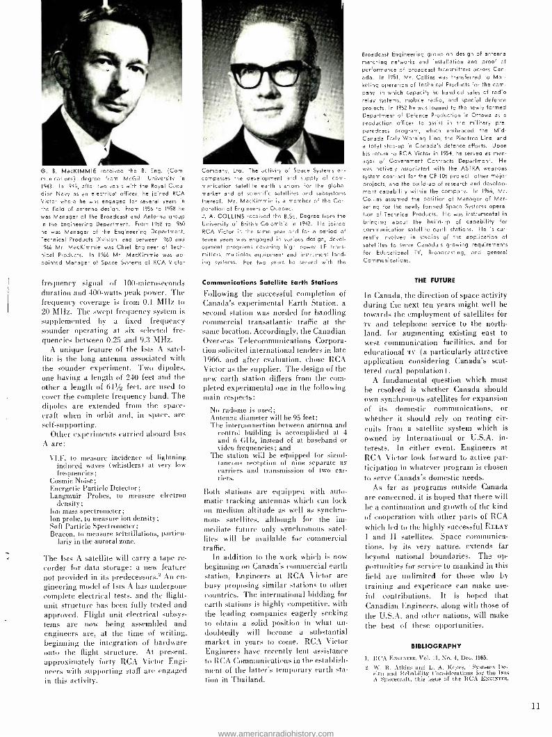
G. 8. MacKIMMIE received the B. Eng. (Com- munications) degree from McGill University in
1943. In 1945, after two years with the Royal Cana- dian Navy as an electrical officer, he joined RCA Victor where he was engaged for several years in
the field of antenna design. From 1956 to 1958 he
was Manager of the Broadcast and Antenna group in the Engineering Department. From 1958 to 1960
he was Manager of the Engineering Department, Technical Products Division, and between 1960 and
1966 Mr. MacKimmie was Chief Engineer of Tech-
nical Products. In 1966 Mr. MacKimmie was ap- pointed Manager of Space Systems of RCA Victor
frequency signal of 100- microseconds duration and 400 -watts peak power. The frequency coverage is from 0.1 MHz to 20 MHz. The swept frequency system is supplemented by a fixed frequency sounder operating at six selected fre- quencies between 0.25 and 9.3 MHz.
A unique feature of the Isis A satel- lite is the long antenna associated with the sounder experiment. Two dipoles, one having a length of 240 feet and the other a length of 611/2 feet, are used to cover the complete frequency band. The dipoles are extended from the space- craft when in orbit and, in space, are self- supporting.
Other experiments carried aboard Isis A are:
VLF, to measure incidence of lightning induced waves (whistlers) at very low frequencies;
Cosmic Noise; Energetic Particle Detector; Langmuir Probes, to measure electron
density ;
Ion mass spectrometer; Ion probe, to measure ion density; Soft Particle Spectrometer; Beacon, to measure scintillations, particu-
larly in the auroral zone.
The Isis A satellite will carry a tape re-
corder for data storage: a new feature not provided in its predecessors.- An en- gineering model of Isis A has undergone complete electrical tests, and the flight - unit structure has been fully tested and approved. Flight unit electrical subsys- tems are now being assembled and engineers are, at the time of writing. beginning the integration of hardware onto the flight structure. At present, approximately forty RCA Victor Engi- neers with supporting staff are engaged in this activity.
Company, Ltd. The activity of Space Systems en-
compasses the development and supply of com- munication satellite earth stations for the global market and of scientific satellites and subsystems thereof. Mr. MacKimmie is a member of the Cor- poration of Engineers of Quebec. J. A. COLLINS received the B.Sc. Degree from the University of British Colombia in 1942. He joined RCA Victor in the same year and for a period of seven years was engaged in various design, devel- opment programs covering high power LF trans- mitters, multiplex equipment and instrument land- ing systems. For two years he served with the
Communications Satellite Earth Stations
Following the successful completion of Canada's experimental Earth Station, a second station was needed for handling commercial transatlantic traffic at the same location. Accordingly, the Canadian Overseas Telecommunications Corpora- tion solicited international tenders in late 1966, and after evaluation, chose RCA Victor as the supplier. The design of the new earth station differs from the com- pleted experimental one in the following stain respects:
No radome is used; Antenna diameter will be 95 feet; The interconnection between antenna and
control building is accomplished at 4 and 6 GHz, instead of at baseband or video frequencies; and
The station will be equipped for simul- taneous reception of nine separate RE
carriers and transmission of two car- riers.
Both stations are equipped with auto- matic tracking antennas which can lock on medium altitude as well as synchro- nous satellites, although for the im- mediate future only synchronous satel- lites will be available for commercial traffic.
In addition to the work which is now beginning on Canada's commercial earth station, Engineers at RCA Victor are busy proposing similar stations to other countries. The international bidding for earth stations is highly competitive, with the leading companies eagerly seeking to obtain a solid position in what un- doubtedly will become a substantial market in years to come. RCA Victor Engineers have recently lent assistance to RCA Communications in the establish- ment of the latter's temporary earth sta- tion in Thailand.
Broadcast Engineering group on design of antenna
matching networks and installation and proof of
performance of broadcast transmitters across Can-
ada. In 1951, Mr. Collins was transferred to Mar- keting operation of Technical Products for the com- pany, in which capacity he handled sales of radio relay systems, mobile radio, and special defence projects. In 1952 he was loaned to the newly formed Department of Defence Production in Ottawa as a
production officer to assist in the military pre- paredness program, which embraced the Mid - Canada Early Warning Line, the Pinetree Line, and
a total step -up in Canada's defence efforts. Upon his return to RCA Victor in 1954, he served as man- ager of Government Contracts Department. He
was actively associated with the ASTRA weapons
system contract for the CF -105 project, other major projects, and the build -up of research and develop- ment capability within the company. In 1966, Mr. Collins assumed the position of Manager of Mar- keting for the newly formed Space Systems opera- tion of Technical Products. He was instrumental in
bringing about the build -up of capability for communication satellite earth stations. He 's cur- rently involved in studies of the application of satellites to serve Canada's growing requirements for Educational TV, Broadcasting, and general Communications.
THE FUTURE
In Canada, the direction of space activity during tie next ten years might well be towards the employment of satellites for TV and telephone service to the north- land, for augmenting existing east to west communication facilities, and for educational TV (a particularly attractive application considering Canada's scat- tered rural population) .
A fundamental question which must be resolved is whether Canada should own synchronous satellites for expansion of its domestic communications, or whether it should rely on renting cir- cuits from a satellite system which is
owned by International or U.S.A. in-
terests. In either event, Engineers at RCA Victor look forward to active par- ticipation in whatever program is chosen to serve Canada's domestic needs.
As far as programs outside Canada are concerned, it is hoped that there will be a continuation and growth of the kind of cooperation with other parts of RCA
which led to the highly successful RELAY
I and II satellites. Space communica- tions, by its very nature, extends far beyond national boundaries. The op-
portunities for service to mankind in this field are unlimited for those who by
training and experience can make use- ful contributions. It is hoped that Canadian Engineers, along with those of
the U.S.A. and other nations, will make the best of these opportunities.
BIBLIOGRAPHY
1. RCA ENGINEER, Vol. 11, No. 4, Dec. 1965.
2. W. R. Atkins and L. A. Keyes, "Systems De- sign and Reliability Considerations for the Isis A Spacecraft, this issue of the RCA ENGINEER.
11
www.americanradiohistory.com
SYSTEM DESIGN AND RELIABILITY CONSIDERATIONS FOR THE ISIS A SPACECRAFT`
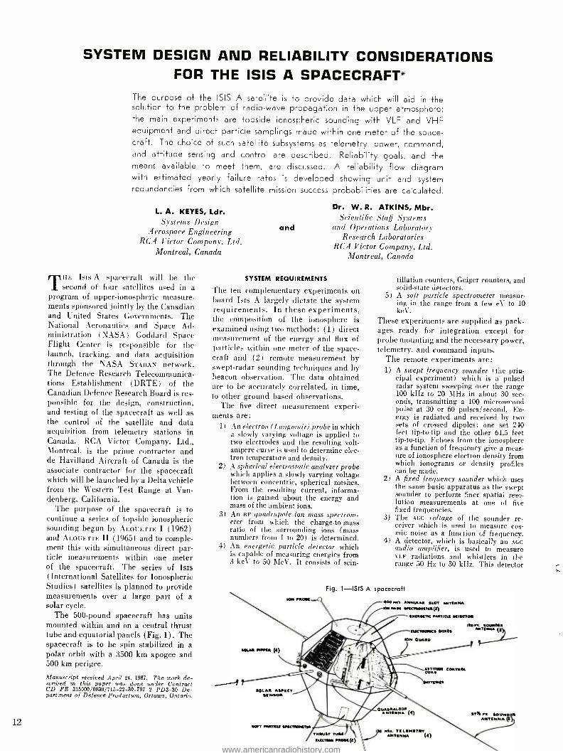
The purpose of the ISIS A satellite is to provide data which will aid in the solution to the problem of radio -wave propagation in the upper atmosphere; the main experiments are topside ionospheric sounding with VLF and VHF equipment and direct particle samplings made within one meter of the space- craft. The choice of such satellite subsystems as telemetry, power, command, and attitude sensing and control are described. Reliability goals, and the means available to meet them, are discussed. A reliability flow diagram with estimated yearly failure rates is developed showing unit and system redundancies from which satellite mission success probabilities are calculated.
L. A. KEYES, Ldr. Systems Design
Aerospace Engineering RCA Victor Company, Ltd.
Montreal, Canada
THF Isis A spacecraft will be the second of four satellites used in a
program of upper -ionospheric measure- ments sponsored jointly by the Canadian and United States Governments. The National Aeronautics and Space Ad- ministration (NASA) Goddard Space Flight Center is responsible for the launch, tracking, and data acquisition through the NASA STADAN network. The Defence Research Telecommunica- tions Establishment (DRTE) of the Canadian Defence Research Board is res- ponsible for the design, construction, and testing of the spacecraft as well as the control of the satellite and data acquisition from telemetry stations in Canada. RCA Victor Company, Ltd., Montreal, is the prime contractor and de Havilland Aircraft of Canada is the associate contractor for the spacecraft which will be launched by a Delta vehicle from the Western Test Range at Van- denberg, California.
The purpose of the spacecraft is to continue a series of topside ionospheric sounding begun by ALOUETTE I (1962) and ALOUETTE II (1965) and to comple- ment this with simultaneous direct par- ticle measurements within one meter of the spacecraft. The series of Isis (International Satellites for Ionospheric Studies) satellites is planned to provide measurements over a large part of a solar cycle.
The 500 -pound spacecraft has units mounted within and on a central thrust tube and equatorial panels (Fig. 1) . The spacecraft is to be spin stabilized in a polar orbit with a 3500 km apogee and 500 km perigee.
Manuscript received April 24, 1967. The work de- scribed in this paper was done under Contract CD FE 315000/0030/715 -22 -30 -797 2 PD3 -30 De- partment of Defence Production, Ottawa, Ontario.
12
and
Dr. W. R. ATKINS, Mbr. Scientific Staff Systems
and Operations Laboratory Research Laboratories
RCA Victor Company, Ltd. Montreal, Canada
SYSTEM REQUIREMENTS
The ten complementary experiments on board Isis A largely dictate the system requirements. In these experiments, the composition of the ionosphere is examined using two methods: (1) direct measurement of the energy and flux of particles within one meter of the space- craft and (2 ) remote measurement by swept -radar sounding techniques and by beacon observation. The data obtained are to be accurately correlated, in time, to other ground based observations.
The five direct measurement experi- ments are:
1) An electron (Langmuir) probe in which a slowly varying voltage is applied to two electrodes and the resulting volt - ampere curve is used to determine elec- tron temperature and density.
2) A spherical electrostatic analyzer probe which applies a slowly varying voltage between concentric, spherical meshes. From the resulting current, informa- tion is gained about the energy and mass of the ambient ions.
3) An RF quadrupole ion mass spectrom- eter from which the charge -to -mass ratio of the surrounding ions (mass numbers from 1 to 20) is determined.
4) An energetic particle detector which is capable of measuring energies from 3 keV to 50 MeV. It consists of scin-
SOLAR N'IR (4)
ION MORS
tillation counters, Geiger counters, and solid -state detectors.
5) A soft particle spectrometer measur- ing in the range from a few eV to 10 keV.
These experiments are supplied as pack- ages ready for integration except for probe mounting and the necessary power, telemetry, and command inputs.
The remote experiments are: 1) A swept frequency sounder (the prin-
cipal experiment) which is a pulsed radar system sweeping over the range 100 kHz to 20 MHz in about 30 sec- onds, transmitting a 100 microsecond pulse at 30 or 60 pulses /second. En- ergy is radiated and received by two sets of crossed dipoles: one set 240 feet tip -to -tip and the other 61.5 feet tip -to -tip. Echoes from the ionosphere as a function of frequency give a meas- ure of ionosphere electron density from which ionograms or density profiles can be made.
2) A fixed frequency sounder which uses the same basic apparatus as the swept sounder to perform finer spatial reso- lution measurements at one of five fixed frequencies.
3) The Acc voltage of the sounder re- ceiver which is used to measure cos- mic noise as a function of frequency.
4) A detector, which is basically an Acc audio amplifier, is used to measure VLF radiations and whistlers in the range 50 Hz to 30 kHz. This detector
Fig. 1 -ISIS A spacecraft
400 Res. ANNULAR SLOT AIeTSNNA NA.' SwI1RSRITIR(I)
INIRNM MRTICN NISOTOR
IUCIROIKs ROSIS
RIN OUARO
gIRE nv" CONTROL
CO
MTr[RIIf
ISO IIOUINR
SOLAR ASPICS SS NSOR
"1:411:::r (4) SOS .r. SOUND R rENNA (S
SW? MRTICLI SIICTR014Ta
THRUST TUBS ILSCIRN moat (t)
Wes. T/LIMITM (4)
www.americanradiohistory.com

LORNE KEYES received the E.Sc. in Electrical Engineering from Queen's University in 1954. He has taken a number of graduate courses at McGill University. He has been employed at RCA Victor Company, Ltd., Montreal, since 1954 on a variety of telecommunication problems including airborne VHF transceivers, UHF troposcatter telephony, and heavy route microwave telephony. He was en- gaged in design and system integration of the NASA RELAY communications transponder and recently participated in communications satellite proposals to COMSAT Corporation. He is a mem- ber of the Quebec Corporation of Professional Engineers, the Engineering Institute of Canada and the IEEE. He is currently Spacecraft Systems Engi- neer for the ISIS A Program.
W. R. ATKINS received the B.Sc. in Electrical Engineering from the University of Alberta in 1956,
and remained there the following year for post graduate studies while holding a lecturer's as- sistantship. He obtained an Athlone fellowship to
is connected to one set of sounder poles and may also be used with a swept exciter to measure ion -resonance effects.
5) A VHF beacon propagation experiment which determines total electron con- tent and scintillations in the iono- sphere between the satellite and a re- ceiving station.
Because coverage beyond that available in real -time telemetry and command is required, a tape recorder and a clock and programmer are included for remote control and data gathering. A minimum of four hours per day of sounding should be possible at the end of one year in orbit, and it should be possible to oper- ate continuously for two consecutive pole -to -pole passes (half orbit) in the same direction.
The requirement for a reasonable probability of operation of the spacecraft for longer than one year is embodied in the spacecraft system reliability goals. The most important of these goals is a 0.8 or better probability (60% confi- dence) of completely satisfactory opera- tion at the end of one year in orbit as based on 2000 hours of main mode operation during that year. (Completely satisfactory operation is defined as a fully operational condition in all equip- ment with the exception of an on -board tape recorder and certain non -essential monitoring channels, solar cells, and programming capability; only one of completely redundant equipments need work. Completely satisfactory operation is a much more stringent criterion than mission success, which is more difficult to specify.) Another important goal is that system design is to be such that the probability of a first failure causing the loss of useful data from more than three experiments should not exceed 0.05.
study in England for the period 1957 to 1959, re- ceiving a Diploma from Imperial College and an M.Sc. from the University of London for work on transistor analog multipliers, and gaining experi- ence in analog computers and transistor pulse cir- cuitry. From 1959 to 1960, he was employed by Canadair working on pulse multiplexing equipment of quasi- static low -level information and environ- mental testing of transistor equipment. In 1960,
he joined RCA Victor Research Laboratories, work- ing on studies connected with radar under ECM conditions and investigating behaviour of noise at very low levels. In 1961, he was awarded a David Sarnoff Fellowship to proceed with his studies at the Imperial College-of the University of London under RCA Corporate Sponsorship, receiving his Ph.D. in 1965 for work on sequential decoding techniques using decision theory. Since returning to the RCA Victor Research Laboratories, he has been advising on technical exhibits for EXPO '67, and more recently, concerned with spacecraft reliability and systems studies.
DESIGN APPROACH
Structure
For the required orbit, the Delta launch vehicle allows a payload weight of 500 pounds. Based on the limits of the max- imum diameter inside the spacecraft shroud and the power requirement of 50 watts (average) body- mounted solar cell arrays were chosen instead of the mechanically more complex erectable - paddle arrays. The requirement for nearly equal power output at all solar aspects dictated the roughly spherical shape: this shape results in an average power output, for random spin -axis orientation, within a few percent of op- timum and has satisfactory thermal and structural properties. The thrust -tube mounting of components provides good accessibility for test and installation, ex- cept for those mounted inside the tube. To maintain dynamic stability, it is nec- essary to locate some of the boxes on the equatorial panels, thus maintaining maxi- mum moment of inertia about the spin axis. A principal feature of the mech- anical design is the great length of the sounding antennae: 240 feet tip -to -tip for one set and 6L5 feet for the other. The large change in moment of inertia (as the pre- stressed tape antennae are extended) produces a despin from 90 r /min (at separation) to 3 r /min.
Thermal control is passive by choice of surfaces and by means of aluminized mylar heat shields which are placed over the ends of the thrust tube.' Major heat flow is along the tube and the mylar blankets introduce a thermal resistance which reduces this heat flow and, as a result, reduces the temperature gradient along the tube. The high temperature extreme for end -on illumination and the
worst -case combination of a fully charged battery and full sunlight is +40 °C. The low temperature extreme of -5 °C oc- curs for a discharged battery and end -on illumination in minimum sun (eclipse) .
The average temperature for random orientation varies by about 30 °C. The thermal blankets are beneath the outer covering of the spacecraft which must appear as a closed electrically conduct- ing sphere for RF continuity. The sur- face of the spacecraft must also present a minimum of 1000 square inches of free metallic area to satisfy experimenters needs.
The spherical electrostatic probe and one of the Langmuir probes are mounted on erectable booms at the top end of the spacecraft. This position is considered necessary to keep the probes from being influenced by the plasma sheath which forms around the spacecraft as a result of voltage induced in the sounder poles as they cut the earth's magnetic field (V x B effect) . This sheath represents an equilibrium condition between the resulting collection of highly mobile electrons and less mobile ions.'
Telemetry
The choice of transmission bands is de- termined by compatibility with the ex- isting 136 -MHz and 400 -MHz NASA STADAN facilities.
The sounder data in natural form is a composite video waveform consisting of calibration, synchronization and echo return pulses in a spectrum from DC to 20 kHz. This bandwidth makes PCM pro- cessing impractical. Although it contains much redundant information and could possibly be processed on board into a more compact form, the simple FM ana- log transmission system proven on ALOUETTE I and II was adopted. This system matches the existing facilities for ionogram preparation, 136 -MHz trans- mission frequency, and 100 -kHz channel bandwidth.
The VLF signals in the band from 50 Hz to 30 kHz are readily accommodated on the same transmission link either on a time -shared basis or by straight sum- mation. The latter technique is possible because the sounder signals are analyzed mainly on a time -domain basis while the VLF signals are analyzed mainly in the frequency domain. The interfering sounder spectra which contains a large proportion of energy at harmonics of the pulse rate can be filtered out or largely ignored. Separate but simultaneous VLF
and sounder can be transmitted at the expense of extra power consumption by putting the VLF on the 400 -MHz link.
A standard 30 -kHz Iamm FM subcarrier modulates the main carrier and is pulse-
13
www.americanradiohistory.com

amplitude modulated (PAM ) by the out- put of a 30- channel essential housekeep- ing commutator. This is multiplexed with a pulse- width -modulated time code to satisfy a data processing requirement that spacecraft time be available on all data links. The PAM essential house- keeping system is used mainly by the satellite controller for quick -look moni- toring of such essential parameters as battery currents and voltages, which are also carried on the PCM system.
Transmission of most direct particle measurement data could be accom- plished simply either by an analog sys- tem of several FM subcarriers on a single carrier or by time multiplexing on a single carrier. However, due to the wide- spread use of the recommended NASA PCM time -multiplex system and the compatibility with present data proces- sing systems, a PCM system was chosen. This system lends itself readily to various data rates by use of super- and sub - commutation but it necessitates complex synchronizing and decommutation equip- ment on the ground. The soft -particle spectrometer and the energetic particle detector have data in digital form which can be conveniently multiplexed into the bit stream. The format chosen is a 24- word frame 60 times per second using an 8 -bit word. Quantitizing errors are con- sistent with the 1 percent accuracy aim for the telemetry system.
Some data are sampled twice per frame (120 words /sec) while others are sampled once per second by one of two 60- channel subcommutators. The syn- chronizing pattern comprises the first 16 bits in a pseudo- random pattern. One bit of the frame carries time code in a non -standard 60 pulse /second BCD for- mat; one bit carries the output of a 60- channel flag subcommutator.
The pci transmission scheme is a split -phase format modulating a PM
transmitter, as this system gives the minimum transmitter power (2W) for the marginal bit error rate of 10-'. The modulation index is adjusted to leave ten to fifteen percent of the nominal power as a residual carrier to permit good carrier lock for coherent reception.
Transmitter powers and deviations are based on the principle of limiting mar- ginal performance at maximum slant range. Assuming the lowest performance telemetry receiver system operating at 15- degree antenna elevation, marginally satisfactory ionograms can be made with a video s/N ratio of 20 dB.
For both FM and PM systems, average performance will be much better than the marginal limits, since marginal con- ditions occur for only a short time.
Both FM and PM transmitters are di-
14
plexed together and duplexed with the command receivers to feed a four -pole turnstile antenna symmetrically mounted around the bottom end of the satellite. This antenna produces an almost omni- directional circularly polarized radiation.
The beacons radiate through four equatorially mounted quadraloop ele- ments fed in quadrature to produce a nearly omnidirectional circularly polar- ized radiation pattern.'
The tape recorder requires four chan- nels: two analog for the sounder and NU'. one digital for the PCM, and one analog for time code. The record and playback speeds are interrelated and are ultimately controlled by the bandwidth and power available for the replay link as well as by the time available for read- out. The 400 -MHz band was the only feasible choice for the replay link and a 500 -kHz channel with a transmitter power of 4 watts allows 65 minutes of recording and a 4:1 speed -up on play- back. This permits a full tape dump on an overhead apogee pass. Normal record periods are 16 minutes, but successive record periods can cover a single pole -to- pole pass.
The 400 -MHz link can also be used as a real -time back -up for the 136 MHz FM and PM. The 400 -MHz transmitter has both FM and PM modulation capa- bility. The sounder, or VLF signals, fre- quency modulate the carrier while a 93 kHz subcarrier normally carrying the PCM data, phase modulates the carrier. Time code in the form of amplitude modulation on a second subcarrier also phase modulates the transmitter. The transmitter radiates from an annular slot antenna, flush mounted at the top end of the satellite, thus there are no pro- trusions near the particle probes that might affect the plasma. Although it would have been desirable not to have any BF field in the region, it was not structurally feasible to put the antenna on the opposite end. In any case, the RF
field produced probably has a negligi- ble effect in comparison with the 400 -watt sounder pulse. To provide some control of the plasma effect produced by the sounder poles near the spacecraft, loose insulating boots or sleeves are fitted over the first few feet at the base of the sounder poles.- A DC bias may also be applied to the sounder poles.
Command System
Based on the large number of experi- ments and the required operational flexi- bility, over 100 separate commands were needed. For compatibility, only NASA command standards were considered. A system that exceeds the 70- command capacity of the tone Digital System and
yet is simpler than the PCM Instruction Command System is an allowable variant of the Tone Command System. This system transmits single tones sequen- tially as AM on a VHF carrier. One of fifteen tones is assigned as a unique spacecraft address and is transmitted first. The execute tones follow to pro- duce a particular command function and may consist of up to 3 tones. The system chosen uses six of the possible seven execute tones in a 3 -tone sequence to give 6' or 216 commands. Essential commands are redundant in the decoder, reducing the possibility of losing both due to decoder faults.
For command switching, each con- verter, or separate load, has a latching relay in series with it which is operated according to command pulses fed through a diode steering matrix. The various modes of operation are described below:
Hain modes activate the experiments and initiate data transmission or recording in one of the most commonly used experi- ment configurations (e.g., "All Experi- ments On "). These main modes require only a single command which is storable for execution at a stored time. This is achieved by a clock and programmer which can store up to five turn -on times in a twenty- four -hour interval and any five of the ten main -mode commands. Space- craft main modes are reset to a standard off condition either by a spacecraft man- ual turn -off or an automatic turn -off.
Spacecraft sub -modes normally provide major modifications to main modes. The modifying commands, which set magnetic latching relays as do most of the com- mands, are reset to the standard main - mode condition when the spacecraft is turned off, either directly or by automatic timer.
Equipment sub -modes are used to switch equipment into relatively perma- nent states of operation (e.g., to engage a redundant unit or to turn off a faulty unit) . These commands are not negated by turn -off.
Experimental sub -modes select the in- ternal modes in which a particular experi- ment will operate. These remain fixed until modified by a further experimental sub -mode command.
The command system consists of redun- dant receivers feeding a command de- coder which distributes command pulses to the command switching unit and to other units (Fig. 2) . A redundant clock and programmer supplies timing signals and time code to other subsystems and provides remote turn on capability. An automatic turn -off unit (ATO) with in- ternal redundancy prevents accidental discharge of the batteries.
Power System
Power for the spacecraft is generated by an array of 11,130 solar cells arranged to form 174 separate circuits with 62
www.americanradiohistory.com
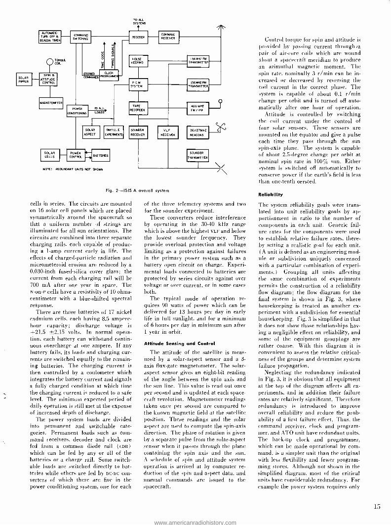
SOLAR PIPER
AUTOMATIC
TURN OFF a BEACON TIMER
OTORQUE COIL
SPIN A - ATTITUDE
CONTROL
MAGNETOI.£fER
SOLAR CELLS
COMMAND SWITCHING
TO ALL SYSTEMS t
STORED COMMAKES
POWER
CONDITIONING
CLOCK PRCE RAMI
TO ALL
LOADS
SOLAR
ASPECT
POWER
CONTROL
DECODER
HOUSE KEEPING
COMMAND
RECEIVER
PCM SYSTEM
PARTICLE
ExPERf.EMS
BATTERIES
NOTE : REDUNDANT UNITS NOT SHOWN
TAPE
RECORDER
SOUNDER
RECEIVER
ULF RECEIVER
136MHZ FM TRANSMITTER
136MHZ PM
TRANSMITTER
400 M HZ
FM /PM
SOUNDER
TRANSMITTER
Fig. 2 -ISIS A overall system
cells in series. The circuits are mounted on 16 solar cell panels which are placed symmetrically around the spacecraft so that a uniform number of strings are illuminated for all sun orientations. The circuits are combined into three separate charging rails, each capable of produc- ing a 1 -amp current early in life. The effects of charged -particle radiation and micrometeroid erosion are reduced by a 0.030 -inch fused -silica cover glass; the current from each charging rail will be 700 mA after one year in space. The N -on -P cells have a resistivity of 10 ohms - centimeter with a blue- shifted spectral response.
There are three batteries of 17 nickel cadmium cells, each having 8.5 ampere - hour capacity; discharge voltage is +21.5 -2.15 volts. In normal opera- tion, each battery can withstand contin- uous overcharge at one ampere. If any battery fails, its loads and charging cur- rents are switched equally to the remain- ing batteries. The charging current is then controlled by a coulometer which integrates the battery current and signals a fully charged condition at which time the charging current is reduced to a safe level. The minimum expected period of daily operation is still met at the expense of increased depth of discharge.
The power system loads are divided into permanent and switchable cate- gories. Permanent loads such as com- mand receivers, decoder and clock are fed from a common diode rail (con) which can be fed by any or all of the batteries or a charge rail. Some switch - able loads are switched directly to bat- teries while others are fed by Dc -Dc con- verters of which there are five in the power conditioning system, one for each
of the three telemetry systems and two for the sounder experiment.
These converters reduce interference by operating in the 30 -40 kHz range which is above the highest VLF and below the lowest sounder frequency. They provide overload protection and voltage limiting as a protection against failures in the primary power system such as a battery open circuit on charge. Experi- mental loads connected to batteries are protected by series circuits against over voltage or over current. or in some cases both.
The typical mode of operation re- quires 90 watts of power which can be delivered for 13 hours per day in early life in full sunlight, and for a minimum Of 6 hours per day in minimum sun after 1 year in orbit.
Attitude Sensing and Control
The attitude of the satellite is meas- ured by a solar -aspect sensor and a 3-
axis flux -gate magnetometer. The solar - aspect sensor gives an eight -bit reading of the angle between the spin axis and the sun line. This value is read out once per second and is updated at each space- craft revolution. Magnetometer readings taken once per second are compared to the known magnetic field at the satellite position. These readings and the solar aspect are used to compute the spin -axis direction. The phase of rotation is given by a separate pulse from the solar- aspect sensor when it passes through the plane containing the spin axis and the sun. A schedule of spin and attitude system operation is arrived at by computer re- duction of the spin and aspect data, and manual commands are issued to the spacecraft.
Control torque for spin and attitude is provided by passing current through )a pair of air -core coils which are wound about a spacecraft meridian to produce an azimuthal magnetic moment. The spin rate, nominally 3 r /min can be in- creased or decreased by reversing the coil current in the correct phase. The system is capable of about 0.1 r /min change per orbit and is turned off auto- matically after one hour of operation.
Attitude is controlled by switching the coil current under the control of four solar sensors. These sensors are mounted on the equator and give a pulse each time they pass through the sun spin -axis plane. The system is capable of about 2.5- degree change per orbit at nominal spin rate in 100% sun. Either system is switched off automatically to conserve power if the earth's field is less than one -tenth oersted.
Reliability
The system reliability goals were trans- lated into unit reliability goals by ap- portionment in ratio to the number of components in each unit. Generic fail- ure rates for the components were used to establish relative failure rates, there- by setting a realistic goal for each unit. (A unit is defined as an engineering mod- ule or subdivision uniquely concerned with a particular combination of experi- ments.) Grouping all units affecting the same combination of experiments permits the construction of a reliability flow diagram; the flow diagram for the final system is shown in Fig. 3, where housekeeping is treated as another ex- periment with a subdivision for essential housekeeping. Fig. 3 is simplified in that it does not show those relationships hav- ing a negligible effect on reliability, and some of the equipment groupings are rather coarse. With this diagram it is convenient to assess the relative critical- ness of the groups and determine system failure propagation.
Neglecting the redundancy indicated in Fig. 3, it is obvious that all equipment at the top of the diagram affects all ex- periments, and in addition their failure rates are relatively significant. Therefore redundancy is introduced to improve overall reliability and reduce the prob- ability of a first failure effect. Thus, the command receiver. clock and program- mer, and ATO unit have redundant units. The back -up clock and programmer, which can be made operational by com- mand, is a simpler unit than the original with less flexibility and fewer program- ming stores. Although not shown in the simplified diagram, most of the critical units have considerable redundancy. For example the power system requires only
15
www.americanradiohistory.com

16
two out of three batteries- and the Command Decoder has redundant eudcs for essential commands with additional safety in the command flexibility. Loss of spin and attitude control would not jeopardize all experiments provided that attitude data were available. Loss of the 100 -MHz transmitter would still leave all data available in the direct transmission mode; the 400 -11Hz transmitter can act as an alternate path for real -time data transmission. but this is not shown in Fig. 3.
Further down the flow diagram. the i' : i encoder affects six experiments. and a single failure will probably jeopardize more than three of them. Thus, a pas- sive redundant encoder is included. The mode power switches tended to contribute a significant failure rate, so
redundant active contacts were used. The remaining groups with relatively large failure rates are in the. sounder system. but it is impractical to use redundancy because there is no unit that has a significantly large failure rate; the
fig. 3- Simplified reliability flow diagram for the ISIS A spacecraft showing failure rates per operating year.
WANC RECE .0 X CLOCK ARMIGRNMER X AT_ uNIT
VNt T.
OCI EKER CONVERTER
SRITCHES 0' I TO a I0, NAG.
IT03
ESS NAG
SIO TOILS
CONVERTER
0.304
G
ESSENTIAL HOUSEKEEPING
COMMUTATOR ' 07593
S C.0 J00O
ISOUNDER Tc., T. CIRCUITS 10 1
MAIN VOCE SMI0CR
CONVERTER
CONVERTER SNITCH
RCM ENCODER SNITCH
TELEMETRY Dr LEVER
007035
AiSc
NAC.
514139,05 AN
-SUIT'
VOL TAG( COAITRO LL ED 05C.
MIRER
CALIBRATOR
I- I AI:. I 5I .
IOOSMC NOISE AV.. 1.
Ty NON ESSEN 11 AI T N LT' THE
SUB COMMUTATOR; _"1890
ION MASS SPI. MD ELECTRON, _S -.w'.'
I
SOFT PARTICLE SPEC 0.00550
ENERGETIC PARTICLE DETECTOR
MO ELECTRONICS 000410
ALI O.
Ielf.E!
CEP NID ELECTRONICS T 00540
SEA AND ELECTRONICS n1.6
135MSt T. DPIERER HITCHING IV MMt T.
complexity is inherent in the experiment and little can be done for improvement. Redundant transmitters are included at
the customer's request and reduce the probability of a first failure effect. The remaining equipment affecting only one experiment has no redundancy.
Even after the preceding improve- ments, the clock and programmer still has the largest failure rate. since it con- tains over one -third of the total number of components ( solar cells excepted ) ;
however. further increases in reliability are impractical. Loss of the clock and programmer would mean loss of remote operation and considerable inconve- nience in the direct transmission mode; however, experimental data would still be available.
Failures will occur. however, so it is important to design such that failures cause minimum possible data loss. For example. the command decoder can af- fect all experiments. but a single gate failure affects only a localized area of circuitry. Therefore the command allo- cations should be such as to place com- mands affecting a single experiment in this localized area so that a failure affects only one experiment (with the exception of redundant commands). A similar approach was used in the design of the commutating circuits. Alterna- tively when such a separation cannot occur, the design should be such that a
failure will only reduce flexibility rather than cause complete data loss.
With the preceding improvements, and the redundancy as indicated in Fig. 3, the calculated probability of completely satisfactory operation at the end of one year in orbit is 0.813, and the probability that a first failure would affect more than three experiments is 0.041. These fig- ures show that the Isis "A" system meets the reliability goals, provided that the units meet their individual reliability goals. Even if the tape recorder were in- cluded in the reliability calculations. the probability of completely satisfactory (operation is still 0.79. When a mission success is defined to require experimen- tal data in the direct transmission mode only. then the clock and programmer and associated remote operation equip- ment do not enter reliability calculations. The probability of a mission success at the end of one year in orbit is then 0.89 with a 60% confidence level.
REFERENCES
1. G. G. Gray, "Thermal Design for the Isis A Spacecraft," this issue of the RCA ENGINEER.
2. F. J. F. Osborne and M. A. Kasha, "Labora- tory Studies of Satellite Design Problems," this issue of the RCA ENGINEER.
3. L. Keyes, J. Zuran, P. Olden, "Command Telemetry and Tracking System for the Isla A Spacecraft," this issue of the RCA ENGINEER.
www.americanradiohistory.com

COMMAND, TELEMETRY, AND TRACKING SYSTEM FOR THE ISIS A SPACECRAFT
The ISIS A satellite telemetry, command, and tracking systems are described in
some detail as are the antennae and units making up the systems. The telemetry system includes two I 36-MHz real -time data links, one FM for sounder video trans- mission, and one PM for PCM transmission. A 400 -MHz link of increased band- width is used to playback tape recorded data at four times the record speed and to act as a real time back -up for the I 36-MHz system. Commands corresponding to main modes of operation of the satellite are stored, along with stored times, in
a content- addressed magnetic memory in the clock and programmer. The
antenna system includes a four -element VHF turnstile fed by a low -loss diplexer and duplexer featuring strip -line couplers and an annular slot 400 -MHz radiator. The extendible sounder antennae are briefly described.
L. A. KEYES, Ldr., P. T. CADEN, Ldr., J. ZURAN
Systems Design, Digital and Analog Equipment Design, and Antenna Design
Aerospace Engineering RCA Victor Company, Ltd.
Montreal, Canada
HE ISIS A ionospheric sounding satel- lite is now under construction at
RCA Victor. The principal experiment aboard this satellite is the ionospheric sounding which is performed by a pulsed swept- frequency signal. The frequency coverage is from 0.1 MHz to 20 MHz. The swept frequency system is supple- mented by a fixed frequency sounder operating at six selected frequencies between 0.25 and 9.3 MHz. A unique feature of Isis A is the antennae asso- ciated with the sounder experiment.
TELEMETRY AND TRACKING SYSTEM
The telemetry and tracking system (Fig. 1) consists of two main subsystems: one for use in direct real -time transmission and the other for transmission of tape recorded data with a speed -up playback (4:1) . The first subsystem operates in the 136 -MHz telemetry band, and the second operates in the 400 -MHz band.
The 136 -MHz portion consists of two redundant pairs of transmitters: one pair of FM transmitters with a 100 -kHz trans- mission bandwidth and one pair of PM transmitters with a 50 -kHz transmission bandwidth. Either FM transmitter is se- lectable on command and is modulated by a sounder video waveform which is an analog signal (nc to 15 kHz) consisting of synchronizing and calibrating pulses at 30 or 60 pulses /second plus echo re- turns. It may be modulated also by the output of a VLF receiver in the 50 -Hz to 30 -kHz band, either on a time -shared
This work was done under Contract CD FE315000/ 0030/715 -22 -30 -797 3 PD3 -30 Department of De- fence Production, Ottawa, Ontario. Final manu- script received May 15, 1967.
basis with the sounder or combined with the sounder. The carrier is continuously modulated by a 30 -kHz tete FM subcar- riers which is normally modulated by the output of a 30- channel essential house- keeping commutator. The commutator output is replaced by clock and program- mer data (60 pulse /second BCD code) for five seconds at the beginning of each minute. The FM transmitter output is fed to a diplexer which feeds a four - element turnstile antenna.
Data from all experiments other than the sounder and VLF are time multiplexed and encoded using one of a redundant pair of PCM encoders'. The output of the encoder in split -phase format is used to phase modulate one of the PM trans- mitters. The transmitter output is du- plexed with the command receivers and feeds the same duplexer and turnstile antenna as the FM transmitter. All de- signs must meet specifications over a temperature range of -5 to +40 °C and must operate over the range -50 to +75 °C°
136 -MHz FM Transmitter
The 136 MHz FM transmitter is a four - watt unit with a basic design that has proven successful on ALOUETTE I and II. It consists of a 17 -MHz crystal oscil- lator employing crystal pulling for frequency modulation. This method re- quires careful control of spurious modes of crystal oscillation to control stability and modulation distortion. The oscillator is followed by three stages of buffering, and doubling by varactor multipliers. The final amplifier is a single 2N3375
transistor feeding the output via a band - pass filter which is necessary to meet the NASA spurious emission requirements.- The design employs conventional dis- crete components and the construction is by a series of individual compartments milled from an aluminum block.
136 -MHz PM Transmitter The 136 -MHz PM transmitter is a two - watt unit consisting of a 34 -MHz crystal oscillator with two sages of buffering and varactor doubling, followed by a final amplifier and filter. The phase modula- tor is a two -varactor high -pass low -pass interstage filter design. In this arrange- ment, the incidental amplitude modula- tions are complementary and so tend to cancel, while the phase modulations add and some of the modulation non- linear- ities cancel. The design of the trans- mitters is similar to that of the FM units.
PCM Encoder
The PCM encoder employs a frame of 24 words of 8 bits each (192 bits) , with 60 frames per second (11,520 bits /sec) .' Some data are in the form of slowly varying voltages in the range 0 to +5 volts with frequency components not over 25 or 50 Hz. These are sampled once or twice per frame, according to the band- width required, by a commutator con- sisting of analog gates connected to a common output. These gates use field effect transistors (FET) as analog switches, and are opened in a sequence defined by a counter using integrated logic circuits. The samples are held by a sample and hold circuit and then encoded by an Ain converter of the cascaded feedback type. The encoder output is stored in a shift register and clocked out at the appropriate time with the most significant bit appearing first in the output. Some data, which are already in the form of bits stored in experiment shift registers, are fed word sync pulses at the appropriate time and bit sync which is then used to clock out the contents of the shift registers. During these intervals, the commutator and Ain converter are inactive.
Two words are available as 16 par- allel access bits for a digital flag sub - commutator and various high speed flags such as a solar aspect sensor and a 60 pulse /second BCD time code. Two analog words are used to carry the output of two 60- channel analog sub - commutators. Frame sync consists of the first sixteen bits in a pseudo- random pattern. Inputs to the redundant en- coders are normally fed by separately buffered outputs but in some cases may be connected in parallel. The encoder design attempts to minimize the prob- ability of loading parallel inputs under
17
www.americanradiohistory.com
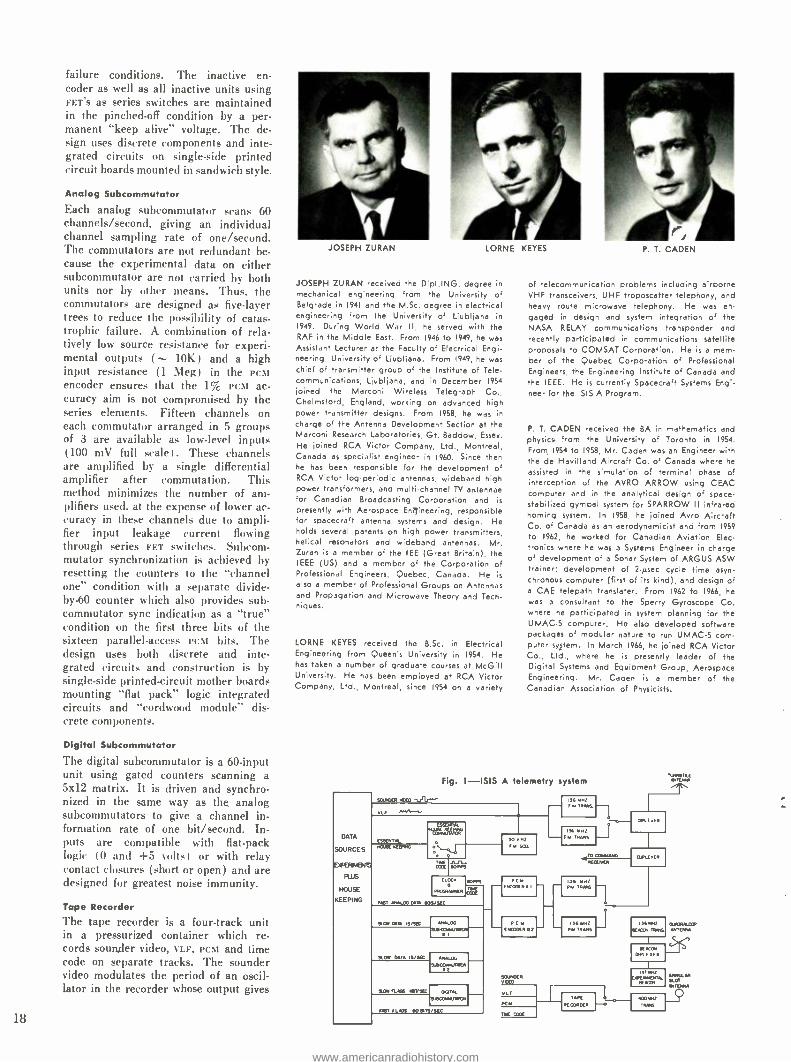
failure conditions. The inactive en- coder as well as all inactive units using FET'S as series switches are maintained in the pinched -off condition by a per- manent "keep alive" voltage. The de- sign uses discrete components and inte- grated circuits on single -side printed circuit boards mounted in sandwich style.
Analog Subcommutator
Each analog subcommutator scans 60 channels /second, giving an individual channel sampling rate of one /second. The commutators are not redundant be- cause the experimental data on either subcommutator are not carried by both units nor by other means. Thus, the commutators are designed as five -layer trees to reduce the possibility of catas- trophic failure. A combination of rela- tively low source resistance for experi- mental outputs 10K) and a high input resistance (1 Meg) in the PCM encoder ensures that the 1% PCM ac- curacy aim is not compromised by the series elements. Fifteen channels on each commutator arranged in 5 groups of 3 are available as low -level inputs (100 mV full scale 1. These channels are amplified by a single differential amplifier after commutation. This method minimizes the number of am- plifiers used. at the expense of lower ac- curacy in these channels due to ampli- fier input leakage current flowing through series FET switches. Subcom- mutator synchronization is achieved by resetting the counters to the "channel one" condition with a separate divide - by-60 counter which also provides sub- commutator sync indication as a "true" condition on the first three bits of the sixteen parallel- access PCM bits. The design uses both discrete and inte- grated circuits and construction is by single -side printed- circuit mother boards mounting "flat pack" logic integrated circuits and "cordwood module" dis- crete components.
Digital Subcommutator
The digital subcommutator is a 60 -input unit using gated counters scanning a 5x12 matrix. It is driven and synchro- nized in the same way as the analog subcommutators to give a channel in- formation rate of one bit /second. In- puts are compatible with flat -pack logic (0 and +5 volts) or with relay contact closures (short or open) and are designed for greatest noise immunity.
Tape Recorder
The tape recorder is a four -track unit in a pressurized container which re- cords sounder video, %LF, PCM and time code on separate tracks. The sounder video modulates the period of an oscil- lator in the recorder whose output gives
18
JOSEPH ZURAN LORNE KEYES
JOSEPH ZURAN received the DipI.ING. degree in
mechanical engineering from the University of Belgrade in 1941 and the M.Sc. degree in electrical engineering from the University of Ljubljana in
1949. During World War II, he served with the RAF in the Middle East. From 1946 to 1949, he was Assistant Lecturer at the Faculty of Electrical Engi- neering, University of Ljubljana. From 1949, he was chief of transmitter group of the Institute of Tele- communications, Ljubljana, and in December 1954
joined the Marconi Wireless Telegraph Co., Chelmsford, England, working on advanced high power transmitter designs. From 1958, he was in charge of the Antenna Development Section at the Marconi Research Laboratories, Gt. Baddow, Essex.
He joined RCA Victor Company, Ltd., Montreal, Canada as specialist engineer in 1960. Since then he has been responsible for the development of RCA Vict log-periodic antennas, wideband high power transformers, and multi -channel TV antennae for Canadian Broadcasting Corporation and is
presently with Aerospace En2Jineering, responsible for spacecraft antenna systems and design. He holds several patents on high power transmitters, helical resonators and wideband antennas. Mr. Zuran is a member of the IEE (Great Britain), the IEEE (US) and a member of the Corporation of Professional Engineers, Quebec, Canada. He is
also a member of Professional Groups on Antennas and Propagation and Microwave Theory and Tech- niques.
LORNE KEYES received the B.Sc. in Electrical Engineering from Queen's University in 1954. He has taken a number of graduate courses at McGill University. He has been employed at RCA Victor Company, Ltd., Montreal, since 1954 on a variety
DATA
SOURCES
DCFETasvas
PLUS
HOUSE
KEEPING
EOEXR MEO
E
.Oca ,
KEEP..
P. T. CADEN
of telecommunication problems including airborne VHF transceivers, UHF troposcatter telephony, and heavy route microwave telephony. He was en- gaged in design and system integration of the NASA RELAY communications transponder and recently participated in communications satellite proposals to COMSAT Corporation. He is a mem- ber of the Quebec Corporation of Professional Engineers, the Engineering Institute of Canada and the IEEE. He is currently Spacecraft Systems Engi- neer for the ISIS A Program.
P. T. CADEN received the BA in mathematics and physics from the University of Toronto in 1954.
From, 1954 to 1958, Mr. Caden was an Engineer with the de Havilland Aircraft Co. of Canada where he
assisted in the simulation of terminal phase of interception of the AVRO ARROW using CEAC computer and in the analytical design of space - stabilized gymbal system for SPARROW II infrared homing system. In 1958, he joined Avro Aircraft Co. of Canada as an aerodynamicist and from 1959
to 1962, he worked for Canadian Aviation Elec. tronics where he was a Systems Engineer in charge of development of a Sonar System of ARGUS ASW trainer; development of 2 -µsec cycle time asyn- chronous computer (first of its kind), and design of a CAE telepath translater. From 1962 to 1966, he was a consultant to the Sperry Gyroscope Co. where he participated in system planning for the UMAC -5 computer. He also developed software packages of modular nature to run UMAC -5 corn- outer system. In March 1966, he joined RCA Victor Co., Ltd., where he is presently leader of the Digital Systems and Equipment Group, Aerospace Engineering. Mr. Caden is a member of the
Canadian Association of Physicists.
Fig. 1 -ISIS A telemetry system
ROE IWrPs
WOO MU IS/Y6 1... LO. COY!
I
9.01. OT is/s¢ 1 ANALOG
.YMQW P.
WM RCS iRVIC .CITA, 91110,4MCP1
PAST EEGs W RIT,,scc
PCM FMDORR2
!OE/QM VOW
VLF
PC 10
PM 36 MN/
TRANS s
,..E I
I
Rm. TRM6 rMEN.E
a ORE.ER
F.1,37 1 MMtM RR(MR x
1 ..p./ m
¡E,..T¡J[r/M
IRECORDER t-- I TAMS
www.americanradiohistory.com

saturation recording on one track; VLF
signals are recorded on a normal AC-
biased track. PCM signals are provided in NRZ -C format but are converted by the recorder before recording, to a split phase format. Time code in a 60 pulses /second BCD pulse -width format is used to amplitude modulate a ref- erence PCM bit rate signal which is recorded on the fourth track. The tape recorder is controlled remotely by com- mands stored in the clock and program- mer and may record for several periods for a total of 65 minutes. The normal record period is 16 minutes at 5 in /sec and the playback is in reverse order at four times this speed. A period dis- criminator restores the sounder video waveform and the split phase recorded PCM data is restored to NRZ -C format. VLF and time code are available with- out special processing in the tape re- corder. The outputs are played back over the 400 -MHz link.
400 -MHz Transmitter
The 400 -MHz transmitter is a four -watt unit with both FM and PM modulation capability and contains a latching relay switching unit for input signal switch- ing of played -back data or real -time data. The RF portion of the transmitter consists of a 17 -MHz crystal oscillator, capable of frequency modulation by crystal pulling, feeding a buffer and varactor quadrupler. For this applica- tion, the crystal must be free of spuri- ous resonant modes over an unusually large band because of the modulation frequencies involved which can be up to 80 kHz. This stage feeds a buffer and tripler circuit via a single tuned phase modulator interstage network. A further buffer and doubler circuit provides 2 watts of power at the out- put frequency which is then used to drive the final amplifier to the required four -watt output level.
A final filter is required to keep crys- tal harmonics from exceeding the speci-
t
DIPLE%ER
DUPLEXER
RECEIVER
RECEIVER
Fig. 2- Command system
COMMAND
DECODER
B
ISPDT) ^
CLOCN
_.,PROGRAMMER
BACK UP
CLOCK
PROGRAMMER
fled output level. The power output is fed directly to an annular slot antenna mounted on one end of the spacecraft. As well as providing input signal switching, the transmitter also contains a non -standard 93 -kHz sco which may be modulated by various played -hack or real -time data. The sco and the played -back time code which appears as a 240 pulse /second modulation on a 46,080 Hz carrier produce phase modu- lation of the 400 -MHz carrier while the sounder and VLF frequencies modu- late the carrier. The transmitter con- struction is nearly identical to that of the 136 -MHz FM and PM units.
Experimental and Tracking Beacons
These units which are identical except for their frequency, radiate 100 mW of unmodulated power and together pro- vide stable frequencies at about 136 and 137 MHz. Their outputs are di- plexed together and radiate through four equatorially mounted quadraloop elements. One frequency satisfies the requirements for a tracking beacon compatible with NASA STADANT facil- ities while the two together are used to study ionospheric irregularities.
The beacon design consists of a seventh -overtone crystal oscillator oper- ating at the output frequency, followed by a buffer and final amplifier. Par- ticular care is taken in the design to minimize the effects of temperature and voltage fluctuation on frequency. Low power dissipation in the crystal also minimizes long term aging effects. Worst case combination of voltage fluc- tuation and temperature shock still re- sult in stabilities better than 10-G with- out the use of crystal ovens. Tests at atmospheric conditions have shown that the difference frequency between bea- cons may vary as little as 10' for pe- riods of 10 minutes during thermal transients. This is probably because of nearly identical construction and frequency- temperature characteristics.
Fig. 3- Command decoder
,OSs,[Ns
COMMAND SYSTEM
The command system accepts approxi- mately 150 commands via radio link from ground stations, decodes these commands into control signals for spacecraft equipment either immedi- ately on reception or after a command delay, and ensures that spacecraft equipment is turned off after a suitable operating period in the event of no reception of a deliberate turn -off com- mand.
Reliability and system design of the spacecraft system and experiments dic- tate different reliability requirements for different commands and functions of the command system. The command switching design separates the commands into four categories: main modes, space- craft submodes, equipment submodes and single commands.'
The command link to the spacecraft consists of an amplitude modulated VHF carrier, which carries a 7 -ary se- ries of tones to the spacecraft in groups of four tones. The first tone is an ad- dress tone, and the next three represent one of 216 6 -ary characters.
The commands decoded by the com- mand decoder affect operating space- craft units directly. However, the clock and programmer is an alternative source for some commands (main modes). The clock and programmer is a simple computer with a content - organized memory of ten words. Each memory word can contain a number from one to ten (ten main modes) and a time of day. The memory contents are continually being scanned and corn- pared to a clock; when the clock time agrees with the time stored in a mem- ory location, the associated stored main mode command is executed. The memory of the clock and programmer is filled by simple commands designated for this purpose.
As the capacity of the spacecraft equipment to dissipate power exceeds the capacity of the solar cells, the main
B +L OG IC
SWITCH
SEQUENTIAL FORMAT IST END BED
CHECKER OCOMMANE O RA T O R E E TONE
STORE STORE STORE STORE
(I OP SI 11 OF SMI CE M
DEC TROEE
RA
2IS COMM OUTPUTS
AND
19
www.americanradiohistory.com

power drain of the spacecraft is called upon intermittently and is drawn from storage batteries. This arrangement requires that the storage batteries be never fully discharged; the automatic turn -off unit is designed to guarantee this condition. When certain space- craft functions are turned on by com- mand, the automatic turn -off unit is turned on also, and (after a suitable interval) causes the appropriate space- craft function to turn off. Thus power consumption is limited in the event of failure to receive a transmitted turn -off command. Fig. 2 is a block diagram showing the interconnection of the units in the command system.
The command receiver decoder com- bination is redundant providing two receiver decoder pairs, each handling 108 different command codes. Those commands requiring redundancy for enhanced reliability are made up of outputs associated with two command codes, one from each receiver decoder pair, combined in a diode "or" circuit.
Some of the decoded commands, redundant and single, go to the clock and programmer, and some to the other spacecraft units. Delayed mode selec- tions originating in the clock and pro- grammer provide alternates for ten of the forementioned commands.
Command Decoder
Each section of the command decoder (Fig. 3) includes equipment perform- ing the following functions: filtering, format checking, memory, and decod- ing. The detected signal from the com- mand receiver is presented to seven filters, where the tone is classified as "address" or some "number" one through six. If the tone is an "ad- dress", power is applied to the de- coder logic; "number" tones following the address tones are stored as decoded lists in flip -flop registers. Upon recep- tion of the third "number" tone, if the message has consisted of one address
Fig. 4 -Clock and programmer
COUNT DOWN
SWORD CONTENT ADDRESSABLE MEMORY
WORD FORMAT
(COMMAND/TIME)
TO AC
and three numbers, and if the dura- tions and spacings of the tones have complied with the required format. voltage is applied to the top of a three -layer tree of transistor switches. 3 in the top layer, 6 in the next. and 108 in the bottom layer. The appropri- ate switches are held open by the con- tents of the flip -flop memory, resulting in a current flow from one of the 108 outputs corresponding to the command code received.
Clock and Programmer The clock and programmer (Fig. 4) consists of an accurate clock, a pro- gram store, command inputs, command outputs, serial data outputs, timing pulse outputs, and control logic. The clock is an accurate (0.5 part in 10r) temperature compensated crystal oscil- lator, whose output is divided down by a counter to provide a time code. The program store is a content -addressed magnetic memory of ten words, each word capable of storing a time of day and one of ten characters correspond- ing to the ten main modes. The con- tents of the program store is defined by a series of commands from the com- mand decoder.
The time of day portions of the pro- gram store words are being continually compared to the time code, and when agreement is observed, the associated mode command is issued, and the time portion of the word is replaced by an inadmissible time (29:00 hours) .
The clock and programmer is paral- led by the back up clock for relia- bility. These two units receive power via a type -C magnetic latching relay.
Automatic Turn -Off Unit The automatic turn -off unit is essen- tially a redundant pair of clocks timing the turn -off of the spacecraft equip- ment. The main unit consists of a magnetic shift register, counting min- ute pulses provided by the clock and programmer. This counter is turned on automatically, and times for sixteen minutes. By command, this time can be changed to eight or twenty -four min- utes. The main unit is paralleled by the back -up automatic turn off unit, which consists of an oscillator and thirty - minute magnetic counter.
RADIATING SYSTEM
The antenna complement of Isis A is a set of crossed dipoles, 61.5 feet and 240 feet long for ionospheric sound- ing, a VHF broadband turnstile array for telemetry and command, a telem- etry UHF annular slot antenna, and a quadraloop antenna array for the bea- con and beacon experiments. The loca- tions and orientations of these antenna elements provide optimum radiation
patterns at minimum mutual coupling. The VHF telemetry and command sys-
tems share the same antenna. In orbit, the attitude of the spin -stabilized space- craft continuously changes with respect to earth and a nearly isotropic radiator is required for continuous telemetry and command operations. A broadband circularly polarized monopole array in turnstile configuration provides the best solution at VHF frequencies. The array is located around the end of the space- craft thrust tube which is attached to the launching rocket by a marman clamp. The sleeve -type monopole ele- ments of the turnstile array have a broadband characteristic with 30% fre- quency bandwidth and have a nominal input impedance of 50 ohms. The PM
and FM transmission use opposite rota- tions of polarization controlled by the phasing characteristic of the telemetry diplexer. The design of the telemetry antenna system is governed by bandwidth requirements; isolation requirements be- tween transmitters and receivers; attenu- ation of harmonics; and high isolation between transmitters to prevent cross modulation between the two transmitters.
The heart of the telemetry antenna system is the S -type diplexer which combines a broadband characteristic with a low insertion loss, low VSWR, and high isolation between transmitter input ports. The S- diplexer, which is a 3 -dB strip -line coupler using Faraday screen- ing, offers particular advantages over the conventional coaxial hybrid when antenna arrays are to be connected in phase quadrature over wide frequency bands. The diplexer provides an isola- tion in excess of 45 dB between telem- etry transmitters at an insertion loss below 0.2 dB. The VSWR at the input terminals of the diplexer is less than 1.05. The power ratio at the two an- tenna ports is within -0.25 dB. The deviation from phase quadrature at transmitter and receiver frequencies is within -i-2 degrees.
The main and standby FM and PM
transmitters are connected to the switch- ing unit, which is operated on com- mand. A system of SPOT latching relays connects the selected FM transmitter to the diplexer and feeds the selected PM
transmitter into the duplexer. The switching unit is combined with the telemetry /command diplexer.
The telemetry /command duplexer isolates the transmitters from receivers by 50 dB and provides an additional 50 -dB attenuation of 2nd harmonics in the path of the PM transmitters. The output port of the duplexer is con- nected to the common transmitter/ receiver terminal of the telemetry /com-
www.americanradiohistory.com
mand diplexer. In the command an- tenna system, the RF signal which is intercepted by the turnstile antenna is fed into the diplexer and picked -up at the common transmitter /receiver ter- minal of the diplexer. From this ter- minal. the receiver signal is fed into the duplexer which provides a 3 -dB power split with an isolation of 40 dB. The two command receivers which are connected to the duplexer feed the command decoder.
The duplexer is designed as a corn - bination of a folded comb -line filter and an S -type 3 -dB strip -line coupler using the same basic design as the telemetry/ command diplexer. The height of the resonators of the comb -line bandpass filter is less than one -sixteenth of a wave- length at 136 MHz, thus resulting in a compact lightweight unit.
The broadband metallic matching sleeves of the turnstile monopole ele- ments are attached to base- mounts by threaded fittings enabling the antennas to survive the high vibration levels at launch. The nominal input impedance (50 ohms) of the monopoles permits connection of dummy loads at the base of antenna mounts for rapid check -out of the telemetry system prior to launch.
The broadband diplexer provides high stability of operation at wide tern- perature variations from -50 °C to +70 °C. Due to the inherent phase quadrature at the ports of the diplexer, the RF harnesses feeding each pair of monopoles are identical. As a result, a small number of soldered cable junc- tions is used, reducing the harness in- sertion loss and increasing the relia- bility of operation of the system.
The 400 -MHz telemetry antenna sys- tem utilizes an annular slot antenna with a back -up cavity. A broadband radial transmission line transformer. forms an integral part of the cavity and matches the antenna to the transmitter over a wide frequency band. The an- tenna system is trimmed for minimum reflection (1%) at the transmitter fre- quency using a shorted coaxial stub.
The annular slot antenna is designed to operate as an electrically short radi- ator near the lower cut -off frequency with surface currents flowing across the near -spherical spacecraft body of one wavelength diameter. The combined effect is a good omnidirectional, lin- early polarized, radiation pattern. The broad doughnut pattern has two nulls in both directions of the spin axis.
The supporting booms for the Lang - muir and ion probes are mounted close to the annular slot antenna and are decoupled from the antenna surface currents by a system of ferrite chokes mounted along both booms. The effect of the metallic booms on the antenna
radiation pattern is thus reduced. The antenna surfaces are highly pol-
ished and form a part of the heatshield of the spacecraft. For the same reason, the antenna back -up cavity is em- bedded in a thermo- insulated container.
The beacon radiating system has mani- fold functions. The antenna array radi- ates a 136 -MHz cw signal for tracking purposes in conjunction with a 137 -MHz beacon for the study of ionosphere irreg- ularities and electron content of the ion- osphere.
The University of Western Ontario is the principal user of the beacon fa- cility for studying isolated inosopheric irregularities. Small -scale variation in the total electron content of the iono- sphere are studied using the differential polarization method (measuring the in- stantaneous difference angle between polarization received at the two beacon frequencies).
The closely spaced frequency method is used to determine the total electron content of the ionosphere averaged over several degrees of orbit path. Simul- taneous amplitude and phase scintilla- tion measurements of the received sig- nal provide information for establish- ing the ionic inhomogeneities responsible for these scintillations.
Depending on the experiments, either circular or linear polarization is used. The antenna provided for these experi- ments is an array of four loop antennas mounted on the equatorial panels be- tween the sounder antenna monopoles. The antennas are fed in phase quadra- ture, providing a circularly polarized pattern in the direction of the spin -axis of the spacecraft and mainly linear po- larization in the direction perpendicular to the spin axis. The quadraloop antennas are shorted quarter -wave transmission - line radiators, capacitively loaded at the open ends by slug -type capacitors.
The individual quadraloops have a nominal input impedance of 50 ohms and are fed by a coaxial -cable phasing network. The common cable junction has an input impedance of 12.5 ohms. The transformation to 50 ohms is achieved by two quarter- wavelength 50 -ohm cable sections in parallel. Thus. the same cable is used throughout.
The beacon antenna system features a novel type of strip -line diplexer, com- bining the two transmitters operating at closely spaced frequencies into a com- mon 50 -ohm antenna terminal. The diplexer consists of a half wavelength 3 -dB coupler with Faraday shielding posts, assisted by two helical resonators. With matched output terminals, the diplexer provides isolation between transmitters in excess of 45 dB at 1% frequency separation over a tempera- ture range from -50 °C to +70 °C.
The insertion losses are 0.9 dB and 0.7 dB between the output and the two input ports of the diplexer. The VSWR
at input ports does not exceed 1.1:1. The sounder antenna system is es-
sentially the same as those for ALOUETTE I and ALOUETTE II. The sounder array has a crossed dipole con- figuration mounted in the equatorial plane of the spacecraft. The dipole radiation pattern is derived from two pairs of monopoles, each pair driven in antiphase by a quasi -coaxial feed sys- tem. The pairs operate sequentially in two bands over the frequency range of 0.1 MHz to 20 MHz, with a crossover frequency at 5 MHz. The length of the shorter dipole and the crossover fre- quency are determined by the pattern requirements allowing a maximum side - lobe level of 10 dB below the main lobe and also to ensure antenna efficiency at the lower end of the high frequency band. The antenna elements are made of preformed tubular beryllium copper tape, and stored in the antenna module before and during launch. The antenna elements are individually extendible in orbit by means of an electric motor mechanism activated on separation from the launching vehicle or on command.
The antenna modules are equipped with speed control circuits which main- tain correct de -spin rate of the space- craft during deployment of antenna elements. The modules are double shielded coaxial units with RFI shielding in excess of 100 dB.
The four modules are radially mounted on the thrust tube of the spacecraft and fed via a combining crossover network mounted inside the thrust tube. The crossover network consists of a low -pass high -pass filter and a TR switch. In orbit, the long sounder antennas cut the lines of earth's magnetic field and build up a potential proportional to VxBL, where V is the spacecraft velocity, B is the earth's magnetic field and L the length of antennas. To free the space- craft from the ion sheath generated by the VXB'L effect, all four antenna modules are equipped with ion guards in the form of cylindrical 3- foot -long silicone rubber sleeves mounted at the root of each antenna element. In addi- tion, the antennas are coupled capa- citively to the crossover network to pre- vent nc from reaching the spacecraft.
REFERENCES
L L. A. Keyes, W. R. Atkins, "System Design and Reliability Considerations for the Isis A Spacecraft," this issue of the RCA ENGINEER.
2. Aerospa_ee Data Systems Standards, NASA GFAC Publication.
3. Inter -Range Instrumentation Group (laic) Doc. los -66.
4. Dr. R. G. Harrison, The Design of a PCM Encode: for the Isis A," RCA ENGINEER, Vol. 12, No. 4.
5. G. Gray, "Thermal design of the Isis A Space- craft," this issue of the RCA ENGINEER.
21
www.americanradiohistory.com

22
THERMAL DESIGN OF THE ISIS A SPACECRAFT
The thermal design of the ISIS A spacecraft was dictated by details of the
structure, orbit mission, on -board temperature limits, and payload power dis-
sipation. Consideration of these factors showed that 'passive' thermal control
of the spacecraft was feasible. A computer programmed multi -node heat
balance analysis is described which has been developed and used to predict spacecraft flight temperatures and evaluate design parameters. The scope of
a thermal- vacuum test program required to establish design integrity is outlined.
AALL the experiments and electrical systems are on the Isis A spacecraft
thrust tube and equatorial panels. (A complete description of the spacecraft is given in Reference 1 ) . Because Isis A will be spin stabilized (with a design spin rate of 3 r /min) net heat inputs will tend to be axially symmetric for any sun -spin vector orientation. As the spin stabilization does not prevent long -term large -amplitude spin -axis excursions all sun -spin vector orientations must be con- sidered. Thus sixteen sloping trapezoidal solar cell panels were used to provide fairly constant solar cell aspect ratio for the complete range of sun -spin vector orientations, without allowing the abso- lute minimum aspect ratio to fall signifi- cantly below the mean. (The solar cell aspect ratio is the projected solar cell
This work was done under Contract CD FE 315000/0030/715 -$3 -30 -797 2 PD 3 -30 Department of Defence Production, Ottawa, Ontario. Final manuscript received May 1, 1967.
G. G. GRAY received the B.Sc. (Honours) in Me-
chanical Engineering from Edinburgh University in
1957; in 1958, he received a Diploma in Applied Dynamics from the same school. After one year with British Nylon Spinners, Mr. Gray joined United Air- craft of Canada in 1960, where he performed vibra- tion and stress analysis on gas turbine designs. In
1963, he joined RCA Victor Company, Ltd., as a
senior engineer. With RCA, he was the Mechanical engineer responsible for Alouette II and the ther- mal design of ISIS A. He is presently the Mechan- ical Project Engineer for the ISIS Program.
G. G. GRAY
Aerospace Engineering RCA Victor Company, Ltd., Montreal, Canada
area in any direction divided by the total solar cell area of the spacecraft.) Solar aspect ratio of a sphere is 0.25 ; values for Isis A range between 0.215 and 0.260.
The estimated electrical power dissipa- tion for the electrical systems is 60 watts continuous over an entire orbit. Depend- ing upon the mode of equipment opera- tion, the instantaneous dissipation range can be from 120 watts to nearly zero. The required flexibility is provided by 51 nickel- cadmium storage cells grouped into three 17 -cell batteries; these can supply power_ in addition to the conver- sion rate at peak demand and low solar input, and store energy during low de- mand and high solar input.
The temperature constraints of vari- ous components of the spacecraft, includ- ing the storage batteries, are -5 °C to
+40 °C. These limits must prevail for all satellite orbit and attitude configurations. This includes the launch phase during which time the spacecraft will not be spinning and for which a special ascent heating calculation must be performed.
THERMAL CONSIDERATIONS
The thermal design techniques used for ALOUETTES I and II were developed further for Isis A.
The average surface properties of the spacecraft are based on the maximum and minimum heat inputs averaged over an orbit. The inputs come from the sun, the earth, and from spacecraft internal heat dissipation ( Fig. 1) .
There are two heat inputs from the earth: infrared radiation due to the earth's internal temperature, and re- flected radiation from the sun (albedo) .
The earth infrared input to the space- craft is a function of altitude, while the solar reflected radiation is a function of both altitude and the angle between the earth -sun and earth -spacecraft vectors. For the nominal Isis A orbit, the average infrared input is about 10% of the solar input, and the reflected solar radiation can vary from a maximum average over
one orbit of about 10% of the solar in- put to zero, depending on the angle be- tween the sun -earth vector and the orbit plane. The maximum instantaneous value of reflected solar radiation is al- most 50% of the direct solar input. The extreme conditions possible are listed in Table I.
In addition to variations in heat flux, there is the possibility of variations in spacecraft -sun aspect. Due to gravitation forces, the orientation of the spacecraft spin axis can change through a large amplitude for periods of several weeks. Thus, the surface of the spacecraft must be designed so that the heat intake is, as near as possible, independent of the spin - axis orientation.
For Isis A, the solar cells are on panels which are part of the external shell. The distribution of solar cells on the surface is dictated by the necessity for having a constant rate of conversion of solar power, independent of the spin -axis orientation' Fortunately, this tends to agree with the thermal need for a con- stant (a /e)xArea, independent of orientation.
In the direction normal to the spin axis, the average heat intakes are:
Direct solar radiation - AH an SP (1)
Earth reflected radiation = AH IXH R (2)
Earth infrared radiation - AH Fit E (3)
Payload power dissipation = P' (4)
The heat loss is AE aT' (5)
Thus, the heat balance is
AT T' = AHaH (SP + R) + AHTHE + P' (6)
In general, similar equations can be written for any orientation of spin axis. Therefore, the spacecraft mean tempera- ture is a function of a/e for the various external surfaces, and, to some extent, is
a function of FI.
Thus, temperature of an earth satellite is affected by surface configuration, radi-
www.americanradiohistory.com

L ST OF SYMBOLS
Surface area
Horizontal projected area
Earth infrared heat flux
Black Laxly radiation shape factor from node i to Male j
Thermal mass
Percent sun
Payload power dissipation
Earth tellret.Nl solar radiation
Heat flux from sun
,laadute temperature
Time
Solar absorptivity wal:.r toq cent. l' :al lu
Cululla 1:11n1Y 1'1'11111 i ta, j Node solar radiation conversion efficiency
Infrared emissivity
I. expo -n2)
.4 A 2sVa d.t
1
J
r n11 _ell
d.4 :t A 2s
Accommodation coefficient
Number of Molecules /unit volume
Stefan Boltznuutu's Constant
Free stream temperature
Mass velocity
Average heat transfer /unit area
Ratio of specific Meats
Tempe-at ire of wall
liana of 11111sí likely molecule speed to spacecraft speed
S sin 9
Angle :uf incidence
Earth aspect ratio Average valles detotcul by a bar.
Fig. 1- Radiation inputs to spacecraft.
RADIATION ARRIVING AT SPACECRAFT
SOLAR BTU /HR
REFLECTED SOLAR BTU /HR
EARTH INFRARED
BTU /HR
PAYLOAD HEAT
BTU /HR
100% SUN 5050 350 590 340
67 % SUN 3330 360 590 0
Table I -Heat inputs to spacecraft.
alive properties of the surface, internal heat dissipation. spacecraft orientation, and orbit parameters.'
The heat dissipation term in the heat balance equation is smaller than the other terms but is significant in establish- ing the radiation coupling required be- tween the spacecraft interior and the surface. For Isis A, high emissivity sur- faces were required.
Passive thermal control is used in the Isis A spacecraft. A passive design is one in which the selection of surface ra- diation characteristics is such that the spacecraft will operate within an accept- able range of temperature limits. The alternative. active control. implies the use of devices which will function in space to control a heater. cooler, spacecraft attitude, radiation characteristics of sur- faces. or any combination of the above. Passive control is inherently simple and the reliability problem associated with actuated components is not present; however, no measures can be taken to compensate for changes in surface prop- erties with time and variations in space- craft attitude or orbit parameters. In
Ar
INFRA RIO
Fig. 2- Insulation.
UPPER HEAT SHIELD f IMPROVED CONDUCTANCE' ACROSS CIRCLED JOINTS
EQUATORIAL PANQ, POLIISHED
(Ç(i
lam`
FIBREGLASS INSULATING
WASHERS
SOLAR PANEL
LOWER HEAT SHIELD
this connection it is virtually impossible to effect a totally passive design for space missions where the distance from the sun to the spacecraft will vary appreciably during the mission. With active control. it is possible to compensate for variations in the factors mentioned above. Most earth -orbiting scientific satellites have passive temperature control designs. whereas deep space probes have semi - active or fully active designs and manned spacecraft have complex active control.
CALCULATIONS
Orbital Temperatures
The thermal design based on average absorptivity, emissivity, areas and heat fluxes produced a temperature range of +2 °C to +35 °C. As the desired tem- perature range is -5 °C to +40 °C, there is a little in reserve. so knowledge of vari- ations of temperature with location in the spacecraft. and with time, was needed. The heat -flow equation (6) can be expanded to include the interactions of thermal masses and the dynamic effects:
RADIATION INSULATION
INTERIOR SURFACE S.
PAINTED
Fig. 3 -Nodal divisions.
23
www.americanradiohistory.com
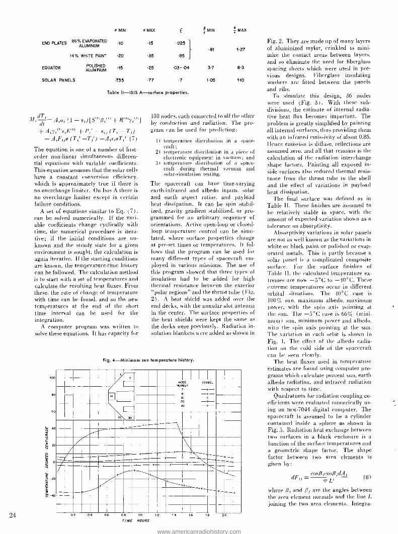
24
END PLATES 86% EVAPORATED ALUMINUM
14% WHITE PAINT
EQUATOR POLISHED ALUMINUM
SOLAR PANELS
a MIN
10
20
15
.735
a MAX
15
35
25
.77
Ê
025
85
03-04
7
a MIN
81
3.7
1.05
MAX
127
8.3
1.10
Table II -ISIS A- surface properties. per
dT
tie
Atat (1 - nt) [Slt)ßlrt) Rruy{ru j
+ Atystt)e,E/t) + P,' - Kti (Tt - Tj) - A,F o (T54 -T,4) -A,E,crT,4 (7)
The equation is one of a number of first - order non -linear simultaneous differen- tial equations with variable coefficients. This equation assumes that the solar cells have a constant conversion efficiency, which is approximately true if there is no overchange limiter. On Isis A there is no overcharge limiter except in certain failure conditions.
A set of equations similar to Eq. (7) .
can be solved numerically. If the vari- able coefficients change cyclically with time, the numerical procedure is itera- tive; if the initial conditions are un- known and the steady state for a given environment is sought, the calculation is again iterative. If the starting conditions are known, the temperature -time history can be followed. The calculation method is to start with a set of temperatures and calculate the resulting heat fluxes. From these, the rate of change of temperature with time can be found, and so the new temperatures at the end of the short time interval can be used for the integration.
A computer program was written to
solve these equations. It has capacity for
100 nodes, each connected to all the other by conduction and radiation. The pro- gram can be used for predicting:
1) temperature distribution in a space- craft;
2) temperature distribution in a piece of electronic equipment in vacuum; and
3) temperature distribution of a space- craft during thermal vacuum and solar- simulation testing.
The spacecraft can have time -varying earth -infrared and albedo inputs, solar and earth aspect ratios, and payload heat dissipation. It can be spin stabil- ized, gravity gradient stabilized, or pro- grammed for an arbitrary sequency of orientations. Active open -loop or closed - loop temperature control can be simu- lated, where surface properties change at pre -set times or temperatures. It fol- lows that the program can be used for many different types of spacecraft em- ployed in various missions. The use of this program showed that three types of insulation had to be added for high thermal resistance between the exterior "polar regions and the thrust tube (Fig. 2) . A heat shield was added over the end decks, with the annular slot antenna in the center. The surface properties of the heat shields were kept the same as the decks were previously. Radiation in- sulation blankets were added as shown in
Fig. 4- Minimum sun temperature history.
100
80
60
NODE SYMBOL NUMBER
7
8 - - 6 -4-
20 -a- ->t- 6
30
20 30 ._- = \
l' °
Y
e ---- o- - o <T:
Y M M M r x
M
. _,`x
z \_ -
..
X
02 04 06 08 10 1.2
TIME HOURS
14 I6 18 20
Fig. 2. They are made up of many layers of aluminized mylar, crinkled to mini- mize the contact areas between layers, and so eliminate the need for fiberglass spacing sheets which were used in pre- vious designs. Fiberglass insulating washers are fitted between the panels and ribs.
To simulate this design, 36 nodes were used (Fig. 3) . With these sub- divisions, the estimate of internal radia- tive heat flux becomes important. The problem is greatly simplified by painting all internal surfaces, thus providing them with an infrared emissivity of about 0.85. Hence emission is diffuse, reflections are assumed zero, and all that remains is the calculation of the radiation interchange shape factors. Painting all exposed in- side surfaces also reduced thermal resis- tance from the thrust tube to the shell and the effect of variations in payload heat dissipation.
The final surface was defined as in Table II. These finishes are assumed to be relatively stable in space, with the amount of expected variation shown as a
tolerance on absorptivity. Absorptivity variations in solar panels
are not as well known as the variations in white or black paint or polished or evap- orated metals. This is partly because a
solar panel is a complicated composite surface. For the surface finishes of Table II, the calculated temperature ex- tremes are now -5 °C to +40 °C. These extreme temperatures occur in different orbital situations. The 40 °C case is 100% sun. maximum albedo, maximum power, with the spin axis pointing at the sun. The -5 °C case is 66% (mini- mum 1 sun, minimum power and albedo, with the spin axis pointing at the sun. The variation in each orbit is shown in Fig. 4. The effect of the albedo radia- tion on the cold side of the spacecraft can be seen clearly.
The heat fluxes used in temperature estimates are found using computer pro- grams which calculate percent sun, earth albedo radiation, and infrared radiation with respect to time.
Quadratures for radiation coupling co- efficients were evaluated numerically us- ing an ism -7044 digital computer. The spacecraft is assumed to be a cylinder contained inside a sphere as shown in Fig. 5. Radiation heat exchange between two surfaces in a black enclosure is a
function of the surface temperatures and a geometric shape factor. The shape factor between two area elements is given by:
cosß,cosß)dA, dFt, _ L5 (8)
where /3, and /3, are the angles between the area element normals and the line L joining the two area elements. Integra-
www.americanradiohistory.com
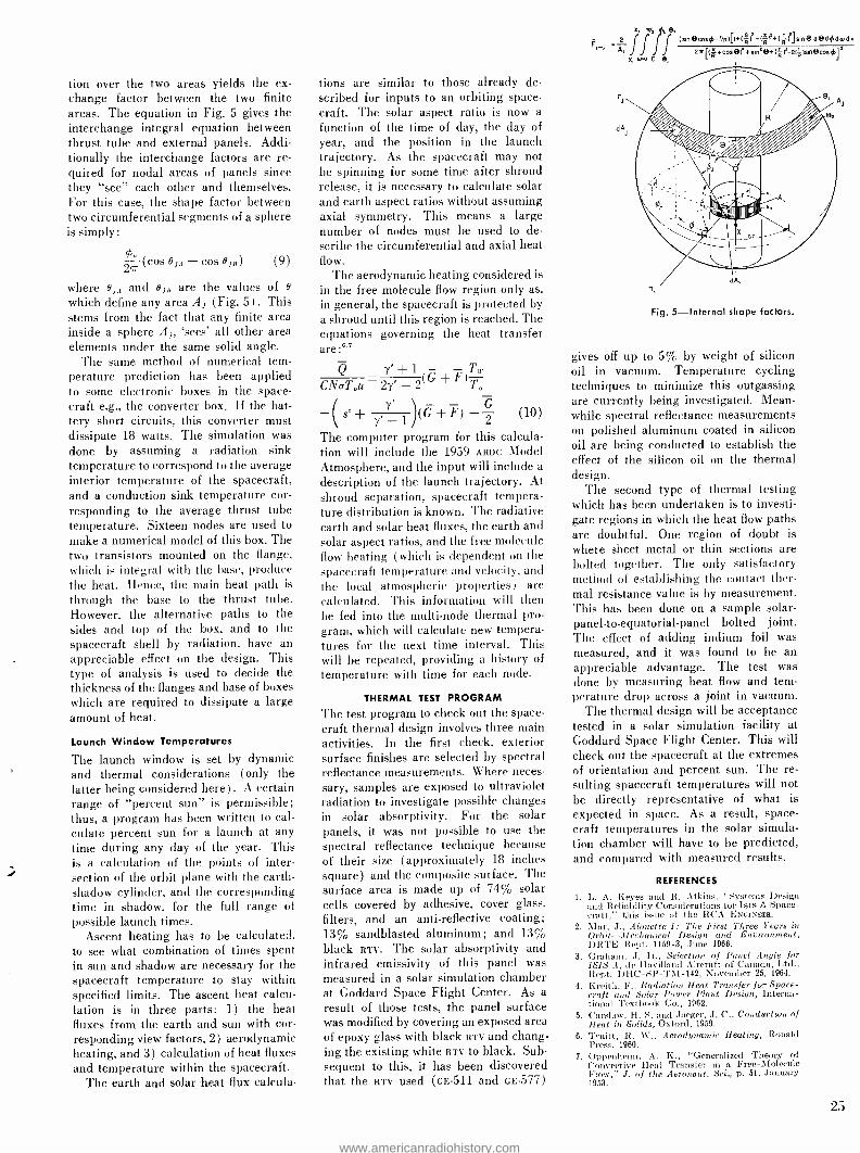
tion over the two areas yields the ex- change factor between the two finite areas. The equation in Fig. 5 gives the interchange integral equation between thrust tube and external panels. Addi- tionally the interchange factors are re- quired for nodal areas of panels since they "see" each other and themselves. For this case, the shape factor between two circumferential segments of a sphere is simply:
(cos 0 j - cos 0 J where eJ,, and eJR are the values of e
which define any area A J (Fig. 5) . This stems from the fact that any finite area inside a sphere A,, `sees' all other area elements under the same solid angle.
The same method of numerical tem- perature prediction has been applied to some electronic boxes in the space- craft e.g., the converter box. If the bat- tery short circuits, this converter must dissipate 18 watts. The simulation was done by assuming a radiation sink temperature to correspond to the average interior temperature of the spacecraft, and a conduction sink temperature cor- responding to the average thrust tube temperature. Sixteen nodes are used to
make a numerical model of this box. The two transistors mounted on the flange, which is integral with the hase, produce the heat. Hence, the main heat path is
through the base to the thrust tube. However, the alternative paths to the sides and top of the box, and to the spacecraft shell by radiation, have an appreciable effect on the design. This type of analysis is used to decide the thickness of the flanges and base of boxes which are required to dissipate a large amount of heat.
(9)
Launch Window Temperatures
The launch window is set by dynamic and thermal considerations (only the latter being considered here). A certain range of "percent sun" is permissible; thus, a program has been written to cal- culate percent sun for a launch at any time during any day of the year. This is a calculation of the points of inter-
./ section of the orbit plane with the earth - shadow cylinder, and the corresponding time in shadow, for the full range of possible launch times.
Ascent heating has to be calculated. to see what combination of times spent in sun and shadow are necessary for the spacecraft temperature to stay within specified limits. The ascent heat calcu- lation is in three parts: 1) the heat fluxes from the earth and sun with cor- responding view factors, 2) aerodynamic heating, and 3) calculation of heat fluxes and temperature within the spacecraft.
The earth and solar heat flux calcula-
tions are similar to those already de- scribed for inputs to an orbiting space- craft. The solar aspect ratio is now a
function of the time of day, the day of year, and the position in the launch trajectory. As the spacecraft may not be spinning for some time after shroud release, it is necessary to calculate solar and earth aspect ratios without assuming axial symmetry. This means a large number of nodes must be used to de- scribe the circumferential and axial heat flow.
The aerodynamic heating considered is in the free molecule flow region only as, in general, the spacecraft is protected by a shroud until this region is reached. The equations governing the heat transfer are
Q y, +1 +F)T CNaTou- 2y' 2 To
-I s'+ F) + 2 (10)
The computer program for this calcula- tion will include the 1959 ARDC Model Atmosphere, and the input will include a
description of the launch trajectory. At shroud separation, spacecraft tempera- ture distribution is known. The radiative earth and solar heat fluxes, the earth and solar aspect ratios, and the free molecule flow heating (which is dependent on the spacecraft temperature and velocity, and the local atmospheric properties ) are calculated. This information will then be fed into the multi -node thermal pro- gram, which will calculate new tempera- tures for the next time interval. This will be repeated, providing a history of
temperature with time for each node.
THERMAL TEST PROGRAM
The test program to check out the space- craft thermal design involves three main activities. In the first check, exterior surface finishes are selected by spectral reflectance measurements. Where neces- sary, samples are exposed to ultraviolet radiation to investigate possible changes in solar absorptivity. For the solar panels, it was not possible to use the spectral reflectance technique because of their size (approximately 18 inches square) and the composite surface. The surface area is made up of 74% solar cells covered by adhesive, cover glass, filters, and an anti- reflective coating; 13% sandblasted aluminum; and 13% black RTV. The solar absorptivity and infrared emissivity of this panel was measured in a solar simulation chamber at Goddard Space Flight Center. As a
result of those tests, the panel surface was modified by covering an exposed area of epoxy glass with black RTV and chang- ing the existing white RTV to black. Sub- sequent to this, it has been discovered that the RTV used (GE -511 and GE -577)
ÌftÌ (sm®cOS-R)I+(R)-(Ri(R)Sin®d®ddmdx
A, 2x'r(R+C°s®)ssini®+(R)s-2(q)sin®COS] x, m.00 6,
dh
Fig. 5- Internal shape factors.
gives off up to 5% by weight of silicon oil in vacuum. Temperature cycling techniques to minimize this outgassing are currently being investigated. Mean- while spectral reflectance measurements on polished aluminum coated in silicon oil are being conducted to establish the effect of the silicon oil on the thermal design.
The second type of thermal testing which has been undertaken is to investi- gate regions in which the heat flow paths are doubtful. One region of doubt is where sheet metal or thin sections are bolted together. The only satisfactory method of establishing the contact ther- mal resistance value is by measurement. This has been done on a sample solar - panel-to- equatorial -panel bolted joint. The effect of adding indium foil was measured, and it was found to be an appreciable advantage. The test was done by measuring heat flow and tem- perature drop across a joint in vacuum.
The thermal design will be acceptance tested in a solar simulation facility at Goddard Space Flight Center. This will check out the spacecraft at the extremes of orientation and percent sun. The re- sulting spacecraft temperatures will not be directly representative of what is expected in space. As a result, space- craft temperatures in the solar simula- tion chamber will have to be predicted, and compared with measured results.
REFERENCES
1. L. A. Keyes and R. Atkins, "Systems Design and Reliuhility Considerations for Isis A Space- craft," this issue of the RCA ENGINEER.
2. Mar, J., Alouette I: The First Three Years in Orbit -Mechanical Design and Environment, DRTE Itept. 1159 -3, June 1966.
3. Graham, J. D., Selection of Panel Aegle for ISIS A, de Havilland Aircraft of Canada, Ltd., Rept. DHC -SP -TM -142, November 25, 1964.
4. Knit i, F., Radiation Heat Transfer for Space- craft and Solar Pouter Plant Design, Interna- tional Textbook Co., 1962.
5. C';uslan-, H. S. and Jaeger, J. C., Conduction of Heat in Solids, Oxford, 1959.
6. Truitt, R. W., Aerodynamic Heating, Ronald Press, 1960.
7. Oppenheim, A. K., "Generalized Theory of Convective Heat Transfer in a Free -Molecule Flow," J. of the Aeronaut. Sci.., p. 51, January 1953.
25
www.americanradiohistory.com
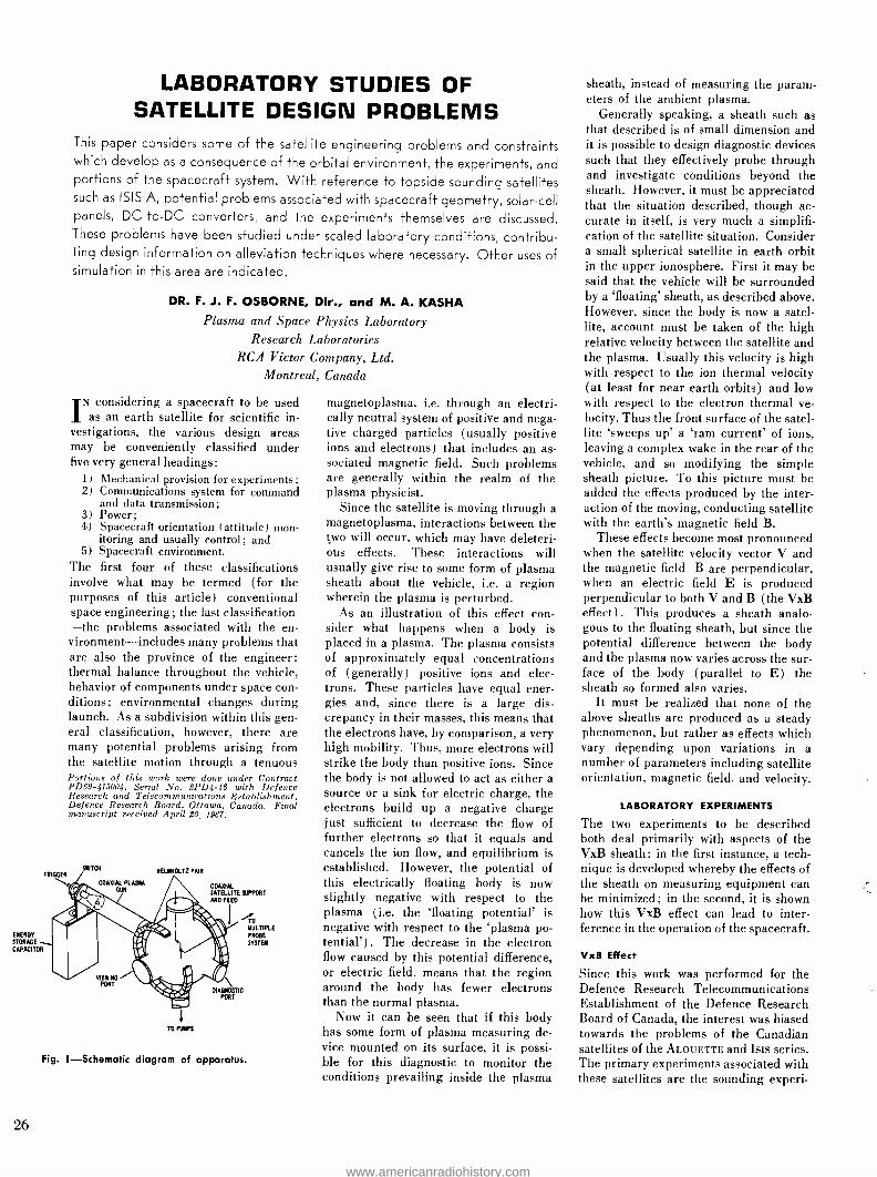
ENERGY
STORAGE
CAPACITOR
TRIGGER
LABORATORY STUDIES OF SATELLITE DESIGN PROBLEMS
This paper considers some of the satellite engineering problems and constraints which develop as a consequence of the orbital environment, the experiments, and portions of the spacecraft system. With reference to topside sounding satellites such as ISIS A, potential problems associated with spacecraft geometry, solar -cell panels, DC -to -DC converters, and the experiments themselves are discussed. These problems have been studied under scaled laboratory conditions, contribu- ting design information on alleviation techniques where necessary. Other uses of simulation in this area are indicated.
DR. F. J. F. OSBORNE, Dir., and M. A. KASHA Plasma and Space Physics Laboratory
Research Laboratories RCA Victor Company, Ltd.
Montreal, Canada
IN considering a spacecraft to be used as an earth satellite for scientific in-
vestigations, the various design areas may be conveniently classified under five very general headings:
1) Mechanical provision for experiments; 2) Communications system for command
and data transmission; 3) Power; 4) Spacecraft orientation (attitude) mon-
itoring and usually control; and 5) Spacecraft environment.
The first four of these classifications involve what may be termed (for the purposes of this article) conventional space engineering; the last classification -the problems associated with the en- vironment- includes many problems that are also the province of the engineer: thermal balance throughout the vehicle, behavior of components under space con- ditions; environmental changes during launch. As a subdivision within this gen- eral classification, however, there are many potential problems arising from the satellite motion through a tenuous Portions of this work were done under Contract PD69- 415004, Serial No. SPD4 -16 with Defence Research and Telecommunications Establishment, Defence Research Board, Ottawa, Canada. Final manuscript received April $0, 1967.
SNITCH
/ COAXIAL PLASMA GUN
HELMHOLTZ PAIR
COAXIAL SATELLITE SUPPORT AND FEED
26
VIEWING PORT
TO PUMPS
DIAGNOSTIC PORT
Fig. 1- Schematic diagram of apparatus.
MULTIPLE PROBE
SYSTEM
magnetoplasma, i.e. through an electri- cally neutral system of positive and nega- tive charged particles (usually positive ions and electrons) that includes an as- sociated magnetic field. Such problems are generally within the realm of the plasma physicist.
Since the satellite is moving through a magnetoplasma, interactions between the two will occur, which may have deleteri- ous effects. These interactions will usually give rise to some form of plasma sheath about the vehicle, i.e. a region wherein the plasma is perturbed.
As an illustration of this effect con- sider what happens when a body is placed in a plasma. The plasma consists of approximately equal concentrations of (generally) positive ions and elec- trons. These particles have equal ener- gies and, since there is a large dis- crepancy in their masses, this means that the electrons have, by comparison, a very high mobility. Thus, more electrons will strike the body than positive ions. Since the body is not allowed to act as either a source or a sink for electric charge, the electrons build up a negative charge just sufficient to decrease the flow of further electrons so that it equals and cancels the ion flow, and equilibrium is established. However, the potential of this electrically floating body is now slightly negative with respect to the plasma (i.e. the `floating potential' is negative with respect to the `plasma po- tential'). The decrease in the electron flow caused by this potential difference, or electric field, means that the region around the body has fewer electrons than the normal plasma.
Now it can be seen that if this body has some form of plasma measuring de- vice mounted on its surface, it is possi- ble for this diagnostic to monitor the conditions prevailing inside the plasma
sheath, instead of measuring the param- eters of the ambient plasma.
Generally speaking, a sheath such as that described is of small dimension and it is possible to design diagnostic devices such that they effectively probe through and investigate conditions beyond the sheath. However, it must be appreciated that the situation described, though ac- curate in itself, is very much a simplifi- cation of the satellite situation. Consider a small spherical satellite in earth orbit in the upper ionosphere. First it may be said that the vehicle will be surrounded by a `floating' sheath, as described above. However, since the body is now a satel- lite, account must be taken of the high relative velocity between the satellite and the plasma. Usually this velocity is high with respect to the ion thermal velocity (at least for near earth orbits) and low with respect to the electron thermal ve- locity. Thus the front surface of the satel- lite `sweeps up' a `ram current' of ions, leaving a complex wake in the rear of the vehicle, and so modifying the simple sheath picture. To this picture must be added the effects produced by the inter- action of the moving, conducting satellite with the earth's magnetic field B.
These effects become most pronounced when the satellite velocity vector V and the magnetic field B are perpendicular, when an electric field E is produced perpendicular to both V and B (the VxB effect) . This produces a sheath analo- gous to the floating sheath, but since the potential difference between the body and the plasma now varies across the sur- face of the body (parallel to E) the sheath so formed also varies.
It must be realized that none of the above sheaths are produced as a steady phenomenon, but rather as effects which vary depending upon variations in a number of parameters including satellite orientation, magnetic field, and velocity.
LABORATORY EXPERIMENTS
The two experiments to be described both deal primarily with aspects of the VxB sheath: in the first instance, a tech- nique is developed whereby the effects of the sheath on measuring equipment can be minimized; in the second, it is shown how this VxB effect can lead to inter- ference in the operation of the spacecraft.
VxB Effect
Since this work was performed for the Defence Research Telecommunications Establishment of the Defence Research Board of Canada, the interest was biased towards the problems of the Canadian satellites of the ALOUETTE and Isis series. The primary experiments associated with these satellites are the sounding experi-
www.americanradiohistory.com

ments whereby the upper ionosphere is investigated by probing with electromag- netic waves (100 kHz to 20 MHz), in a technique somewhat similar to radar. Satellites are used for these measure- ments because of their mobility and ac- cessibility. Since the upper levels of the ionosphere respond to electromagnetic waves of a frequency which will not pass through the layer situated below these upper levels they cannot be investigated from the ground, and so must be probed from above, or the topside, producing the generic name `topside sounder' for such satellites. A characteristic of such topside sounder satellites is that they carry very long sounding antennas (Isis A has approximately a spherical body of one meter diameter, and main antennas 36.6 meters long, i.e. -73 m tip -to -tip). Thus, because the total VxB voltage var- ies directly as L ( -70 m for Isis A), even though the magnetic field B may be small, the velocity V is large and under certain conditions of satellite orientation and velocity the total Vx&L voltage developed can be as much as 20 volts. It can be shown that the maximum potential difference occurs at one end of the anten- nas. However, a potential difference of 10 volts developed about the middle of the antennas (i.e., on the body) is still sufficiently large that it can produce a
sheath capable of disturbing the direct measurement experiments located on or within -1 meter of the body.
Such a situation was studied in the laboratory using an apparatus in which the plasma /satellite interaction is simu- lated. Models of the satellite were sus-
Fig. 2- Langmuir probe analogy.
SHEATH LIMIT
V)(B.L
(a) NO RAM CURRENT
EGATIVE POTENTIAL
i
COLLECTED
CURRENT DENSITY
PLASMA
POTENTIAL (VP)
BODY
COLLECTION
(r) ANTENNA COLLECTION I BIAS
B.L _ VX 2
(BODY POSITIVEI
pended in an evacuated interaction cham- ber and a plasma produced by a two - electrode coaxial plasma gun was allowed to flow down a flight tube into the inter- action chamber and around the model. A magnetic field was produced by a
Helmholtz coil arrangement set up exter- nal to the interaction chamber, as shown in Fig. 1. Thus, a plasma flow was pro- duced with a magnetic field B arranged to be perpendicular to the plasma veloc- ity vector V, producing an electrical field E perpendicular to both V and B
and parallel to the antennas of the model satellite. This arrangement produced the field E in the plasma, leaving the satellite a unipotential body, a situation analogous to the space condition of an electrically field -free plasma and a potential gradient restricted to the vicinity of the satellite.'
The first consideration with such an apparatus, since it is not a true but a
scaled simulation, is how accurate is the scaling? To evaluate this it is necessary to determine first the scaling laws that apply and then determine values for a
number of laboratory plasma parameters and compare them with the predictions derived from the scaling laws. These scaling laws were investigated by Shkar- ofsky` who showed that the plasma pa- rameters required to simulate a typical orbit were a density of ,--10" to 10" cm-', at a temperature of <1 eV, and a velocity of -2 cm /As through a magnetic field of
X350 gauss. These requirements were met reasonably well.'
The techniques used to determine the plasma parameters included Langmuir probes to determine the plasma temper- ature and also, from a variation in the floating potential across the stream, the VxB field; 9 -GHz microwaves for the variation of plasma density with voltage on the plasma gun; and, using a gauss - meter to measure the magnetic field, the previous electric -field measurement was used to measure plasma velocity.
Having established the parameters of the pulsed plasma stream and ensuring that they met the scaling requirements, the model satellite (consisting of a
spherical body with two extended anten- nas) was placed in the interaction cham- ber. Considering the Langmuir charac- teristic of the plasma and assuming the satellite to act in an analogous fashion led to the conclusion that a bias voltage applied between the body and antennas would minimize the sheath problem in the body region (Fig. 2) . For simplicity, the body and the antennas are considered to be of the same cross sectional area. The varying potential difference between the body and the plasma, represented by the absissa, is considered as a gradient along the body, and the current density
FRELEIGH J. F. OSBORNE was educated at the
Royal Canadian Naval College (1946 -48); obtained his B.Sc. at McGill University in 1950 and was
awarded h's M.Sc. at Laval University in 1951 for a
thesis on Application of the Secondary Electron Emission Multiplier to a Mass Spectrometer. In 1954
he received a D.Sc. from Laval University for a the- sis on Secondary Electron Emission of Beryllium Cop- per. He joined the Research Department of Cana- dian Marconi Company in 1954 as a Senior Physicist, working primarily in the fields of component reli- ability, systems, and instrumentation. In 1956, he
was made a supervisor and as such directed a
variety of projects. He transferred to the Electronic Tube Plant where he developed an S -band Electron Beam Parametric Amplifier. In January 1961, he
joined the Research Laboratories of RCA Victor as
a Senior Member of Scientific Staff. He has since been particularly active in the area of plasma measurements and techniques, leading and con- tributing to programs on plasma diagnostics, plasma loaded microwave structures, laboratory simulation of geophysical phenomena, and labora- tory studies of the interactions between a satellite and its plasma environment. In 1965, he became Director of the Microwave and Plasma Physics Lab-
oratory, now the Plasma and Space Physics Labora- tory. He was active in the Royal Canadian Navy (Reserve) from 1946 -1956, is a member of the Cana- dian Association of Physicists, the American Physical
Society, and the American Geophysical Union. He
is Chairman of Commission IV of the Canadian National Committee of the International Scientific Radio Union (URSI), a member of the National Research Council of Canada Associate Committee on Radio Science and the Defence Research Board of Canada Advisory Committee on Physics Research. He has been associated with McGill University teaching a class in plasma physics, and is listed in
American Men of Science.
MICHAEL KASHA received the B.Sc. in Physics
(Honours) in 1957 from London University. After a short time as a Lecturer in Mathematics and
Physics at the Harrow Polytechnic, he joined the
United Kingdom Atomic Energy Authority (UKAEA) at Harwell, to work in the Controlled Thermonu-
clear Reactions Division. There he was engaged on
plasma physics studies, working on the Spider ex-
periment, an investigation of shock waves in a
plasma. This work entailed the design, construc- tion and operation of 40 kV, 20 kilo¡oule device. In 1961 he transferred to the Culham Laboratory of
the UKAEA, to work on Tarantula, a similar experi- ment using a IDO kV, 100 kilo¡oule machine. He
was concerned with the development of a 100 kV,
1.4 million ampere fast- acting (20 nsec) switching
system and various other aspects of the design and
construction. He devised and developed various
diagnostic devices (e.g., multicoil magnetic probes, optical interferometers, and time resolved spec- trometers). Mr. Kasha joined the Research Labora- tories of RCA Victor Company, Ltd. in 1964, since
which time he has been engaged in studies of satel- lite interaction with the ionosphere. He is an Asso-
ciate of the Institute of Physics in London.
27
www.americanradiohistory.com

14
12
'S 10
B
LI 6
67 44
2
GUN'. 2kV
PRESSURE'. 2.104 mmHg.
B -3.510 -2 teslas
4 12 16 20
BIAS VOLTS
24 IS 32
Fig. 3- Variation of plasma /vehicle potential difference with bias.
SOLAR CELL EDGES EXPOSED TO PLASMA
Fig. 4 -Power supp y.
collected at each part of the body is re- presented by the ordinate (electron cur- rent shown as positive). The addition of a ram -ion current, caused by the 'sweep- ing up' of ions discussed previously, has little effect on this curve.
It can be seen that the smallest sheath is associated with the smallest body/ plasma potential difference, and with the electron collection region. Thus a bias applied as shown, causing the body to become the electron collecting portion of the system, should ensure that the body has the smallest sheath
To test this concept, a model satellite was constructed so that a variable poten- tial bias could be applied between the body and the antennas. As was men- tioned above, the plasma sheath is asso- ciated with the potential difference be- tween the plasma and the body, and so this was used as a diagnostic for the sheath. The plasma potential (in fact `floating' potential) was measured by a probe located in the plasma, near the model but outside any possible sheath effects. This potential was measured and compared with the potential of the body of the satellite. The difference between them was plotted as a function of the body /antenna bias (Fig. 3) , and it can be seen that this difference goes to zero, signifying a minimum sheath for a bias >_ 18 volts which corresponds to VxB-L /2 as predicted in Fig. 2.
The experiment thus shows that the bias concept is effective, and calculations of the DC -to -Dc converters used on the given in Osborne and Kasha' show that the system is easily applicable to a satel- lite of the ALOUETTE or Isis type, for a very small power cost ( -'20 mW) . This technique is being applied in the Isis A spacecraft.
28
HELIUM AT 0.2 TORR N. >2 A IQ9 e /cmA
-20 -16 -12
-l2
a _n
I0
-9
_g
'eV_2
-6
CONSTANT DRIVE CURVES PROBE DRIVE 5 VOLTS p -p TEST FREQUENCY 200 H.
PROBE BIAS 20 VOLTS
DAYTIME, LARGE V,
PROBE BIAS 0 VOLT
NIGN7TIME, LARGE VeB
3
`NI%NTTIME. NO V.B
I
DAYTIM E, NOV:B
-8 -2 0 A
SHEATH ASYMMETRY (VOLTS)
I I
I 6 20
Fig. 5 -Plot of VLF 'coupled signal amplitude' under constant amplitude probe drive voltage.
VLF Interference
Analysis of the output of the VLF receiver on ALOUETTE I showed the presence of signals at the frequency (and harmonics) satellite power supply. This is an obvious form of interference but, since it has been observed to mix with the natural signals and form combination tones, and since the level of the automatic gain con- trol of the VLF receiver can be set by the level of interference signals, it is virtually impossible, at times, to discriminate be- tween the true signal and the interfer- ence, or even to know the correct signal level when this discrimination is possible. Inductive interference, or `pick -up' is of course a common problem in circuit de- sign of all kinds, and this was borne in mind during the design of the satellite system, and was moreover checked out before launch, when it was found to be detectable, but at a level considered to be not important. It appears that the inter- ference really developed when the satel- lite was in orbit. It must also be noted that this interference did not occur at a constant level, but showed a definite vari- ation. Examination of the data from the ALOUETTE led to certain patterns being established for the behaviour of this inter- ference: variations associated with satel- lite being in the dark or light part of its orbit with a sharp discontinuity at satel- lite dawn, and also variations which could be linked to the satellite orientation with respect to a plane defined by the satel- lite's velocity vector and the earth's mag- netic field, i.e. a possible dependence on the presence of a VxB effect. Such pat- terns led to the conclusion that the inter- ference was in some way associated with the plasma around the vehicle, and hence a possible mechanism, based on such an assumption, was developed and tested.
versus sheath asymmetry voltage and probe bias
Specifically, any proposed solution had to explain the following observations:
1) With the satellite in the dark, aligned so that no VxBL potential gradient exists along the antennas, no converter interference is found in the VLF receiv- er output;
2) With the satellite in the dark but with VxB gradients, negligible effects were noted;
3) With the satellite in the light but no VxB, no interference; and
4) With the satellite in the light and aligned for a VxB gradient, large in- terference signals are found.
Fig. 4 shows a simplified power supply system for ALOUETTE I. A series -parallel array of solar cells with their terminals exposed to the surrounding plasma sup- ply (via a diode) power to the batteries and various satellite systems. Where the power supply impedance is not zero, the chopping frequency of the electrical DC-
to-Dc converter will appear on the main power bus. Now when the satellite is in the dark, the solar cells are at the body potential and the diode is biased off to prevent battery drain, and so any AC
signal on the power bus is unable to reach the solar cells. When the satellite is illuminated, however, the diode has a low impedance, allowing the converter signal to appear across the solar cells, which are now raised to various positive DC potentials. It remains to determine how this signal will appear on the VLF receiver antenna with VxB modulation.
The VLF receiver antenna is a large dipole, coupled via a transformer, to the VLF receiver in such a way that any alter- nating current of the appropriate fre- quency passing through the transformer between the two halves of the antenna, or unequally between each half antenna and the satellite body, will appear at the VLF receiver input. Now a satellite
www.americanradiohistory.com

can have associated with it asymmetric VxB plasma sheaths, in such a way that all the electron collection required to keep the system electrically floating takes place at one point, usually one end of the antenna array (Fig. 2) . Now if there is an AC signal on the exposed edges of the solar cells, which are themselves raised to a positive potential by their operation, the solar cells will collect a varying elec- tron current. Then, to maintain the floating condition, a variation of opposite phase must occur in the electron current collected on the antenna, which immedi- ately introduces an asymmetric signal through the transformer to the body, as discussed above, and consequently intro- duces an interference signal at the input of the VLF receiver. In the light of this proposed mechanism, consider now the four conditions previously set forth.
1) Satellite in the dark, with no VxB gradient: no converter signal is pres- ent on the cells since the diode is biased off. Any residual signal would affect the antennas symmetrically and there is thus no interference at the receiver.
2) Satellite in the dark, with VxB sheaths: The VxB gradient is such that the body (and cell) potential is approximately VxBL /2 below the plasma potential and the AC signal is not sufficient to raise the solar cell potential into the electron collecting region, and thus the cells are free to change their potential without affecting the current collection pattern.
3) Satellite in the light, but no VxB ef- fects. The solar cells are now at a pos- itive potential, and so a variation of electron collection develops on the an- tennas, but it does so symmetrically and so no interference is found.
4) Satellite illuminated and suffering VxB potential gradients produces the correct asymmetry for the converter signal, to affect the electron collection and thus induce a modulation in the electron current collected by one an- tenna and so produce an asymmetric signal which can appear at the VLF receiver. The converter signal appears on the exposed edges of the solar cells which are now at a large positive potential with respect to the plasma potential.
Such a situation was simulated in the laboratory, where an equivalent satellite system, effectively containing a trans- mitter transformer, antennas, variable VxB antenna sheaths, and an exposed solar cell terminal (which could be raised to a DC potential and have im- pressed upon it a converter signal) was placed in a stationary helium plasma. The results of this simulation are shown in Fig. 5 which shows the magnitude of the detected interference signal for the four conditions discussed above. The lack of symmetry and the fact that the minimum does not occur at zero VxB potential are due to inherent coupling introduced by the model and circuitry
unbalance. Such a picture illustrates well the operation of the proposed mech- anism, and agrees well with the spin modulation data from the satellite.'
SUBSIDIARY WORK
The previous section has dealt in some detail with two laboratory investigations of satellite /plasma interactions to give some idea of the method of approach used and the techniques employed by the plasma physicist in dealing with such problems. The techniques can of course be applied to a broader field than that implied by the above examples.
Kasha and Johnston' have used very similar techniques to investigate the re- sponse of a plasma diagnostic device mounted on a satellite as a function of satellite orientation. A gold plated sphere was used to simulate a satellite, with a total current monitor, or collector, mounted on the surface, the whole being situated in a pulsed flowing plasma. By rotating the sphere around an axis per- pendicular to the plasma velocity vector, the response of the current monitor was determined as a function of satellite ori- entation in such a manner that the effects of the ram current and the wake found behind the simulated vehicle could be clearly seen. As a further experiment a magnetic field was produced over the volume of the plasma stream /satellite model region, parallel to the axis of rota- tion of the model. This produced a VxB potential gradient effect which was now superimposed onto the previous response curve. This second response curve, now highly asymmetric where before it had been symmetric about the plasma veloc- ity vector, was determined experiment- ally, and found to compare well with that of the EXPLORER VIII satellite.
Other aspects of this satellite work have included a study by Graf and Jassby5 of the behaviour of antennas in a plasma. The impedance of an antenna is usually determined by its geometry and the dielectric constant of the sur- rounding medium. Should this antenna be mounted on a satellite, it will find itself in a plasma, i.e. a medium whose dielectric constant may change, either with antenna position (different locations within the satellite orbit) or time. Obvi- ously such changes will bring about changes in the antenna impedance which are related to the plasma parameters.
Such studies as this are useful both to the engineer, since they illustrate such phenomena as a varying antenna imped- ance, and to the physicist, since they indicate new methods for determining the parameters of the space plasma.
At present the RCA Victor Research Laboratories are conducting some pre-
liminary investigations into the phenome- non of `transmitter- induced sheaths'. These plasma sheaths are formed around transmitting antennas under the influ- ence of the antenna operation, i.e. the presence of a pulse of varying high volt- age. The main point of interest is not so much the creation of such sheaths, but the prospects for their persistence once the generating signal has been removed, since they can be of such magnitude as to seriously perturb the operation of the satellite or its experiments. The sheaths, and their relaxation times, are found to depend markedly on the transmitter fre- quency and on the ambient plasma. Pre- liminary results indicate that it may be possible for the relaxation time, under certain conditions, to overlap the time period when the local -plasma diagnostic experiments may be activated, a time of the order of a millisecond. The determi- nation of these relaxation times is compli- cated by the internal circuitry of the particular satellite under consideration and therefore the study is being contin- ued with the aid of an equivalent circuit, with which it is hoped to simulate, though not directly, the action of the ram ion currents, electron currents, etc.
CONCLUSION
In this article one of the parts played by the plasma physics laboratory in the essentially engineering problem of de- signing a satellite has been described. It can be seen that the general approach adopted in the laboratory to these prob- lems is that of simulation, either direct or scale model experiments. The partic- ular scaling laws that must be used for such experiments have been well estab- lished, and the techniques that are used to produce plasma of the correct, scaled parameters are being continually im- proved. Indications have also been given as to the various other fields where work has been, or is, being performed with a view to acquiring a greater understand- ing of the interactions that occur between a fast moving satellite and the ambient magnetoplasma.
REFERENCES
I. F. J. F. Osborne and M. A. Kasha, The VxB Interaction of a Satellite with its Environment ", Can. J. Phys., 45, 2, 263, 1967.
2. I. P. Shkarofsky, "Laboratory Simulation of Disturbances Produced by Bodies Moving Through a Plasma and of the Solar Wind - Magnetosphere Interaction ", Astronautica Acta 11, 3, 169, 1965.
3. F. J. F. Osborne and F. H. C. Smith, R. E. Barrington, and W. E. Mather, "Plasma In- duced Interference in Satellite VLF Receivers ", Can. J. Phys. 45, 1, 47, 1967.
4 M. A. Kasha and T. W. Johnston, "Laboratory Simulation of a Satellite -Mounted Plasma Di- agnosti3 Experiment ", J. of Geophys., Res., Aug. 1967.
5. K. A. Graf and D. L. Jassby, "Measurements of Dipole Antenna Impedance in an Isotropic Laboratory Plasma ", IEEE Trans. Antennas and Propagation, Sept. (1967). RCA Victor Research Report No. 7- 801 -52, 1966.
29
www.americanradiohistory.com
ELECTRICAL AND MECHANICAL DESIGN OF THE MILL VILLAGE ANTENNA -RADOME COMPLEX
Requirements for a satellite communication ground station must be determined from the optimum conditions of 1-he global ComSat system. The most im-
portant characteristic is the gain -to- noise -temperature ratio (and its fading)
which must be optimized for a given cost. Additional requirements are the
compatibility with other ground stations, communication reliability, minimum
design risk, easy operability and maintainability, low operational cost, and long
life. Special requirements were presented for the Mill Village station by the
Canadian environment. This paper discusses the electrical and mechanical
design of the inflated radome and antenna. The system has full -angle and
polarization tracking capability, including orientable linear polarization. The
system has been built and has met all the original design and communication performance objectives.
P. FOLDES
Space Systems Engineering
RCA Victor Ltd.
Montreal, Canada
EVER since the usefulness of micro- waves for point -to -point communi-
cations was recognized, designers have searched for large antenna gain at eco- nomical cost. The advantage of large gain as a means of reducing transmis- sion losses was obvious; nevertheless (for economical reasons), the desired antenna gain had to be balanced with the subsystem characteristics of the en- tire network. Thus, the development of communication antennas was limited not only by their own problems, but by the characteristics of the related equipment.
INITIAL MILL VILLAGE ANTENNA DESIGN CONSIDERATIONS
Orbiting satellites, carrying at least one of the repeater stations, removed the larger part of the propagation path from the vicinity of atmospheric and ground - noise sources. In the case of the down link, the inherent geometry eliminated most of the background radiation from the sensitivity region of the ground - based receiving antenna. The drastic reduction of external noise levels gave tremendous impetus to the development of compatible low -noise antennas and receivers. Under these new circum- stances, the antenna gain (G) was no
Final manuscript received June 16, 1967.
30
and I. SCOTT
Design Engineering
Missile and Sur /ace Radar Division
DEP, Moorestown, N. J.
longer the overwhelmingly important characteristic, and the gain-to- system- noise- temperature ratio ( G/T, ) was introduced.
Usually, the occurrence of a new prob- lem is followed by an early solution based more or less on brute force methods. Earth station antennas were no exception, and some large -gain, low -noise antennas were built, where economy (though im- portant) was of secondary consideration. However, the situation quickly reversed, and new characteristics were defined to measure the cost effectiveness of the de- sign. This effectiveness can be expressed as the G /T, ratio relative to the weight of the antenna.
During the past decade, the state -of- art in satellite communication has favored a large ground antenna, close to 60 -dB gain. The frequency bands have to satisfy the following conditions:
1) for reception -giving minimum corn - bined atmospheric and galactic noise ra- diation; and 2) for transmission -high enough to per- mit adequate receive -transmit isolation and low enough to avoid excessive antenna tolerance problems.
When hemispherical angular coverage and high -precision tracking (1 /10 of the 3 -dB beamwidth) are added to the
above defined requirement of effective- ness, the possible antennas are reduced to a very limited number.
In these antennas, without exception, the large aperture area (.s 6000 ft`) is realized by a parabolic reflector illumi- nated by a spherical wave. The effective- ness of such an antenna is determined by the shape of the main reflector. As the cost of the large, precision reflector and its associated structure is usually far more than the cost of the source (feed system) a great effort went into the de- sign of source systems which produce nearly ideal aperture distributions.
In a global communication system with many satellites and earth stations, the standardization of the G /T, ratio is highly desirable. Thus, effective radi- ated power of the satellite can be se- lected optimally to obtain economical advantages in the construction and op- eration of Earth stations.
EARTH STATION OBJECTIVES
In 1963, the Canadian Department of Transport decided to build, for Canada, an experimental earth station terminal. The declared objectives of the station were:
1) Create a tool by which specifications and design data for operational ground stations can be generated;
2) Permit participation with other na- tions in satellite communication ex- periments;
3) Aid participation with other nations in the development of international oper- ating procedures and standards;
4) Develop Canadian knowledge in sup- plying operational earth stations for Canada and for international market;
5) Train staff for operational use; and 6) Conduct experiments on various hard-
ware units and system aspects in order to permit adaptation of the station for future operational use.
RADOME- ANTENNA REQUIREMENTS
On the basis of the above considerations, the following requirements were estab- lished for the antenna.
1) Frequency Band -3960 to 4200 MHz receive, 6160 to 6400 MHz transmit. In actual practice, these frequency bands (limited by the feed system only) were exceeded by a fair margin.
2) Gain -More than 58 dB (in the re- ceiver frequency band) to assure 600 voice channel or one color -vv channel capability, with currently used satel- lite power. (The gain achieved was approximately 1 -dB higher).
3) System Noise Temperature -Less than 65 °K at 7.5° elevation above the hori- zon at 4GHz in clear weather. The measured value on the completed sys- tem was a few degrees better than the specification.
4) Angular Tracking- Tracking is gen- erally characterized by angular cover- age, accuracy, speed, and acceleration.
www.americanradiohistory.com

TABLE I- Measured Antenna Gain of Mill Village Antenna System
f (GHz) Gain (dB)
factory field
3.9 58.8 58.0
4.0 59.0 59.1
4.1 59.1 59.2
4.2 59.3 59.4
6.0 61.2 59.9
6.1 61.2 60.6
8.2 61.1 59.6
6.3 61.5 59.7
6.4 61.2 59.6
TABLE Il- Calculated and Measured Antenna Noise Temperature Versus
Elevation Angles
O (degrees; Noise Temperature ( °K)
Calculated Measured 90 28.0 34.2
60 28.5 33.8
30 29.5 38.1
10 39.0 44.0
7.5 41.5 47.6
f = 4081 MHz
the
The smallest angular coverage, and minimum speed, are required for syn- cronous satellites. For medium -orbit satellites, full beam steering capabili- ties are desirable. Therefore, tracking speeds and accelerations were speci- fied according to these types of satel- lites. The rms tracking accuracy had to be less than Mo of the 3 -dB beam - width to make tracking loss negligible (equivalent to about 0.02 °).
5) Polarization Matching -To avoid ex- cessive signal loss, the polarization of the "receive" antenna had to be matched to the incoming polarization. Similarly, the transmitter antenna had to be matched to the "receive" polari- zation of the spacecraft. Generally, orthogonal polarizations were needed between transmit and receive modes to obtain additional isolation between these frequencies. Changeover time from circular to linear polarization was not critical, but alignment of the at- titude of linear polarization had to be instantaneous.
6) Weather Protection -The ideal weather protection is a function of the site, but generally the effects of weather cannot be completely eliminated. The magnitude and time distribution of the weather- originated fading (about 3 to 6 dB) can be influenced by the type of antenna protection. In systems under radomes, the main source of fading is precipitation, while in sys- tems without radomes, the main sources are precipitation and wind. The choice of radome -protected or exposed antennas was not clearcut on the basis of GIT, ratio; the choice was based on operational and life -time considerations.
ANTENNA ELECTRICAL DESIGN
Effectiveness of the antenna system as previously defined is maximum for sym- metrical structures (axially symmetrical
paraboloid) which are the most com- monly available design. Therefore, it was decided to tailor the rest of the optical system to fit this arrangement; furthermore, the choice of a far -field Cassegrainian feed system was selected on the basis of its advantages in equip- ment layout, simplicity, and high G /T, ratio (Fig. 1) .
When the Mill Village program be- gan, an RCA experimental feasibility study of a multimode wideband tracking - communication feed had been completed and was the basis of the hardware de- sign. The requirements of the feed (radiating source, Cassegrainian subre- flector, and supporting frames) were as follows:
1) Optimum performance -to -cost ratio for the antenna complex (performance is characterized by ratios of antenna gain to noise temperature) ;
2) Minimum of microwave component types;
3) Large flexibility in operational modes, and coverage of a wide frequency band to accommodate possible changes of frequency requirements;
4) Low circuit loss and difference -mode minimum depth by using highly sym- metrical waveguide cross -sections;
5) Good aperture field distribution for the main reflector in the receiver fre- quency band, while maintaining at least -3 -dB antenna efficiency in the transmitter frequency band;
6) Freedom for field alignment of the feed relative to the main reflector; and
7) Both circular and orientable linear polarization.
The first requirement virtually dictates the use of some form of Cassegrainian system, in which the radiating source first illuminates a primary reflector, re- flecting the wave toward a secondary reflector. In the simplest form of Cas- segrainian system, the radiating source aperture is small and the subreflector is in its far field. Then the subreflector is a symmetrical hyperboloid and the secondary reflector is a symmetrical paraboloid. Mechanical symmetry results in the simplest construction and mini- mum weight. An 85- foot -diameter solid paraboloid with a focal distance of 36 feet and RMS surface tolerance (half - path- length error) of less than 0.040 inch was selected for the main reflector. Such a paraboloid is easily fabricated and has known mechanical characteris- tics; it represents a good compromise among weight /aperture -area ratio, rigid- ity, and weight of feed -support structure.
To illuminate a relatively flat parab- oloid with low spillover, requires an illuminating aperture of ten or more wavelengths. Therefore, an 8.5 -foot- diameter hyperboloid subreflector with a focal distance of 18 feet was used.
The radiating source system can be operated in a linearly polarized mode and may be oriented in any plane. In principle, this system is relatively sim- ple and, with the exception of the mode filter, does not contain any radically new elements.
The transmitter (Tx) terminal (wa- 159) accepts power up to 10 kilowatts cw. Power is divided into two equal parts; each half travels through a cutoff section and a bandpass filter that provide more than 125 -dB attenuation below 4200 MHz, and exhibit less than 0.13 -dB at- tenuation for the Tx frequencies. In addition to these filters, the arm con- nected to the side output of the source system has an adjustable phase shifter using a short -slot hybrid with non - contacting plungers. The outputs of the Tx bandpass filters are connected to the receiver (Rx) bandpass filters at the junctions (S) and (C) ; these form the duplexing points, with negligible junc- tion effects. Beyond these junction points, both the center and side -arm transmitter power is divided into four equal parts by identical wideband hy- brids. (The four -way power division is necessary to introduce monopulse track- ing capability for the receiving band.) After these manipulations, the center power and side -arm power are recom- bined in a four -port orthogonal coupler that has four square -waveguide outputs. Each of these cross -sections support the TE1e and TE°1 modes corresponding to the center and side outputs of the sys- tem. Each of these modes is decomposed in the following symmetrical diamond transformers and converted into a left and right circularly polarized wave by the 90° differential phase shifter that terminates the four -port circuit.
The four -port polarizer launches four individual TE10 modes into the mode fil- ter, an oversized square -waveguide sec- tion having two basic purposes: 1) match the four -port circuit to the multi - mode horn, and 2) produce a symmet- rically tapered field distribution in the aperture of this horn.
An oversized square -waveguide cross - section capable of supporting the TE1°, TE11, TEm, TE.,, + TM21, and TES modes was used. This waveguide, approxi- mately 2 X long, has a series of crosses at the input end for matching the sum and difference modes and a series of posts at the output end for pattern shap- ing. The mode filter is followed by a square horn that has a 5 X aperture size in the transmitting band.
The operation of the system for the received frequencies is basically iden- tical to that for Tx operation, although the direction of propagation is opposite
31
www.americanradiohistory.com

32
TX O--PD I
sloes OUTPUT ADJUST
PHASE SHIFTER
CUTOFF SECTION
TX BAND- PASS
FILTER S
RXI
HCUTOFF SECTION
ADJUST PHASE
SHIFTER
TX BAND- PASS
FILTER
BAND STOP_ FILTER
BAND STOP FILTER
DUPLEXER
02 O
RX BAND- PASS
FILTER
RX BAND PASS
FILTER
4 WAY POWER DIVIDER
IMONOPULSE I COMBINER WIDE
IBAN D
POLARIZER
4 PORT 4 PORT 4 PORT ORTHO- :DIAMOND@ DIFF GONAL TRANSE u
PHASE COUPLER SHIFTER
C I WIDE *--1 HY
CENTRE' BAN
OUTPUT I
L_
°Ico 02c
SA O
DI
O
HYBRID
WI E
BAND HY
I
DZAv-I HYBRID
HYBRID D
HYBRID
HYBRID
DIAMOND TR
Fig. 1 -Block diagram of the feed system.
and band -stop filters are used in the receive arm of the duplexer instead of the cutoff waveguide sections of the transmit arm.
The difference -mode operation of the system is somewhat unconventional, mainly because it combines two inde- pendent monopulse systems. One mono - pulse system is realized in the center multimode system and is obtained through the three wideband hybrids of the monopulse combiner. This system is quite effective, even though the dif- ference -mode aperture is only 1/2 the optimum value. This limitation is re-
IRVING SCOTT received the BSME from Penn State
University in 1941. He joined the Navy Department, Phila. Pa., in 1941 as a production engineer and in 1943 worked at Jacobs Aircraft as production engineer on airplane engines. Over the next ten
years, Mr. Scott gained considerable experience in government and industry positions as a project
DIAMOND TR
DIAMOND TR
J LODE( FILTER
SQUAR HORN
E
AUX HORN NO I
AUX. HORN NO 2
AUX HORN NO 3
AUXILIARY SYSTEM
DIAMOND TR
AUX HORN NO 4
moved by the addition of an auxiliary four -horn monopulse system consisting of four circularly -polarized rectangular horns located symmetrically around the multimode square center horn. The horns are diagonally fed, and circular polarization is achieved by the selection of horn length and aperture aspect ratio.
Conversion of the feasibility design study into operational field hardware took approximately 11/2 years. Most of the electrical tests were done in RCA Victor's anechoic chamber, and consisted of amplitude and phase pat- tern recordings of the radiating source,
engineer in development of ammunition, product design of motor coaches and engine design of air- craft carrier launchers. In 1955, he joined RCA as a
project engineer on the BMEWS tracking radar involved in planning, estimating and design; he
specialized in precision gear -train design, hydrau- lic drives and electro- mechanical devices. From
1963 to 1965 he served as Technical Advisor on the inflatable radome, antenna and pedestal assembly work for the Mill Village earth station. He made the concept design and assisted RCA Victor Ltd. in their contacts with the Canadian Government. He is currently with M &SR at Moores- town, N. J. Mr. Scott is a licensed professional engineer in the state of Pennsylvania.
PETER FOLDES received his diploma of electrical engineering from the Technical University of Buda-
pest in 1950. From 1950 to 1956 he was a research engineer at the Hungarian Telecommunication Research Institute, where he did his postgraduate work. During the same period he lectured at the Technical University. In 1957 he joined RCA Victor
vswa and isolation tests at the vari- ous terminals, and loss measurements through various channels of the system. All measurements had to be conducted in wide- frequency band, and for various polarization modes and polarization posi- tions. Since no scale model of the an- tenna was ever built, great effort was maintained to predict the performance of the antenna system after the installa- tion of the feed.
The efficiency, noise temperature, pointing, and tracking accuracy of the overall system were calculated using computer programs. An improvement in state of art was achieved in predicting the final G /T to within á few tenths of a decibel.
The most important feed system pat- terns and overall antenna system pat- terns are indicated in Figs. 2 and 3 re- spectively. Table I shows the achieved antenna gain. Table II exhibits the noise temperature versus elevation angles for dry weather conditions. It may be noted that the completed system not only achieved the specified gain and noise tem- perature, but its performance is still unique as compared to 85 -ft diameter antennas in the same frequency band.
MECHANICAL CONSIDERATIONS
The antenna and pedestal combination was designed to meet the specific point- ing accuracy requirements and natural frequencies, provide means for data take- off from each axis, and provide for mounting electronic equipment behind the antenna assembly.
The antenna pedestal assembly con- sists of a stationary base azimuth- and elevation -rotating assemblies, and the antenna assembly. The stationary base provides for levelling. The azimuth ro- tating assembly mounted on the station- ary base provides trunnion supports for
Company, Ltd., Montreal. His work covered a wide range of radar and communication systems, micro- wave transmitters, transmission lines, filters, anten- nas and propagation. In recent years he has made extensive studies on Cassegrainian feed systems and ground antennas for satellite communications. He is a member of the IEEE.
www.americanradiohistory.com

72°
the elevation rotating assembly which supports the microwave optics.
Natural Frequencies
The natural frequencies of a system can be defined as those frequencies where the system tends to oscillate or vibrate when acted on by some external force.
To determine the significant frequen- cies consider the system as two lumped masses with a connecting spring. A force applied to one mass results in two resonant frequencies: the locked -rotor resonant frequency and the free -free resonant frequency. The locked -rotor frequency is one at which the amplitude of motion at the system input is mini- mum. The motion at the output does not reflect this decrease in amplitude. At the free -free frequency, however, there is a peaking of the amplitude of motion both at the input and the output of the spring -mass system. It is noted that the free -free frequency is always larger than the locked -rotor frequency. Also, at both frequencies, the decrease in ampli- tude at the locked -rotor frequency or the increase at the free -free frequency is dependent upon the amount of damping in the system.
These frequencies are discussed here since they are very important considera- tions in designing an antenna pedestal assembly and drive system. There are many other resonance frequencies for the structure, but they are higher and usually do not affect system perfor- mance.
Pointing Accuracy
The pointing accuracy for the antenna system may be defined as the angular difference between the direction of prop- agation of the electro- magnetic wave at the maximum RF power density in the vicinity of the satellite and the angular direction indicated by the position -data output shafts. Pointing accuracy for the antenna and pedestal assembly only may be defined as the peak, mechanical angular -error summation for the azimuth and elevation axes from the theoretical RF beam axis to the output shaft on each
axis to which the shaft -position sensors are attached.
A pointing accuracy of 0.17° for the antenna and pedestal assembly per axis was achieved, limited by practical limita- tions in manufacturing, assembly, erec- tion and measurement accuracies. These limitations in accuracies or errors can be divided into bias or DC errors and random errors. Bias errors such as azimuth and /or elevation axis inclina- tion and feed -horn deflection due to gravity are constant and may be pro- grammed out. Random errors such as effects of wind and /or solar radiation are not constant and cannot be pro- grammed out.
The antenna is driven in azimuth by two 5 -hp servo motors counter -torqued to eliminate backlash in the gear trains; the antenna is driven in elevation by one 5 -hp servo motor. Backlash was elim- inated by providing sufficient unbalance about the elevation axis on the counter- weight side so that the teeth of the drive pinion were always in contact with those of the elevation bull gear.
The parabolic reflector is 85 feet in diameter and has a focal length -to-
diameter ratio of 0.42. The reflector surface consists of solid, adjustable, aluminum panels. Electrical continuity is provided mechanically along all edges inside the reflector periphery. During erection of the antenna, the reflector was measured, using optical techniques, at 0, 45, 90 (zenith) and 180 degrees in elevation. A computer program was writ- ten expressly for the measurement and analysis of data; a best -fit parabola of 0.37 -inch RMS was attained.
The hyperbolic reflector is 8.5 feet in diameter, has an RMS surface accu- racy of 0.012 in., and is supported by a quadrupod.
This hyperbolic reflector can be posi- tioned axially by remote control of a motorized drive mechanism, and later- ally, vertically and angularly by manual means. The surface of the reflector was measured mechanically; those param- eters necessary to define its surface were varied within certain limits; and another
TABLE Ill- Antenna
Characteristics Number of ac servo motors Rotational travel (degrees) Velocity (max) a /sec. Acceleration (max) a /sec.2
Pedestal Characteristics
Azimuth
2
+300 and -300 0 to 3
0 to 3
Elevation 1
-2 to +182 0 to 3
0 to 3
Locked rotor frequency (Hz) 2 2
Max. breakaway friction (ftlhf) 20,000 14,000
Max. running friction (ftIbf) 18,000 11,200
Weight of pedestal (lb) 590,000
Weight on azimuth bearings (lbs) 500,000
Elevation load inertia referred to elevation axis and excluding gear train (slug -ft2)
2,000,000
Azimuth load inertia, referred to azimuth axis and excluding gear trains (slug -ft2)
2,000,000
i ii111
Ñ
'iiig .i 1 - 45° PLANE - -E PLANE I li r ú iii H aÓ1i11 i nib 1i i1liii 4IAnN1IMMM IL1f/IIMliúMM
MIMI 30db IFIIIMINII 1111INIIMMIN1MA
IMMIIIIMMIMMLaIMI MEMITIMIïMïIIIIISMI Iminïwars
72° 36° 0
ANGLE
Fig. 2- Measured source pattern at 4.1 GHz.
36°
computer program was employed to determine the best -fit hyperbolic surface.
The quadrupod was designed to re- duce blockage under transmitting and receiving conditions and limit relative translational and rotational movement of the hyperboloid relative to the paraboloid. The feed cone was designed to house the feed system, two parametric amplifiers, tracking downconverters and front ends, stable local oscillators, noise measuring equipment and other test instruments.
Electrical energy was made available to the rotating portions of the antenna pedestal assembly from the stationary base by means of a maypole -type cable windup device. Cables were designed and fabricated to withstand torsion as well as bending stresses. From the azi- muth to the elevation rotating structure, electrical cables were supported on cylindrical sections mounted at the ele- vation axis to accommodate an elevation rotation of 180 degrees.
The parametric amplifier mounted in the antenna assembly required cooling to 4.2 degrees Kelvin. This was accom- plished through the use of a state -of-
the -art closed -cycle cryogenic (helium) system. To provide sufficient on- the -air time for the earth station, two closed - cycle systems were installed in parallel and provided with automatic switchover from one to the other in case of malfunc- tion. These were installed on the azi- muth rotating platform.
A data take -off device is attached to
each axis of the antenna pedestal through a bellows -type flexible coupling. The mechanical characteristics of the antenna pedestal are summarized in Table III. The antenna pedestal was designed for a six -weeks duty cycle as follows:
5 weeks: The entire system to be 'on the air' 24 Hours/ Day (regardless of standby time). Hours /Day 24 Days /Week 7
Targets /Day 24
33
www.americanradiohistory.com

DB
0
-10
20
-30
40
-50
-60
-70
-80
-90
-100
-110
SIDE OF
-ENVELOPE
, r- `
L1111I_J- LOBE
''MAIN
{
ENVELOPE 'PATTERN
.OJT
H 95 °PLANE
PLANE HORN
BLOCKAGE
HYPERBOLD
OF
D `
3% IN
DRUPOD PLANE OF
BLOCKAGE OUADRUPOD
E
T PLANE SPILLOVER
¡- ISOTROPIC LEVEL
- _
_
I
SCATTER SURFACE
FEED
CAUSED
TOLERANCES
SYSTEM
BY
Pll VER
.01 A2 .04 A81 10 100 180 8
Fig. 3a- Antenna system pattern calculated from the source pattern at 4.1 GHz.
Minutes /Target 40 Prugröwmed steering (acquisition) 1 min. Automatic tracking (after acquisition) 35 min.
(minimum) Return slew (180 °) 4 min.
Standby (after each target) 20 min.
1 week: Standby of the entire system with complete shutdown permissible not to exceed 1 week /yr plus 4 hrs /mo for planned maintenance.
The reliability required was 97% mini- mum; the downtime for the antenna pedestal was not to exceed 3% or 262 hours of any given one year period dur- ing the ten year life span. The down- time was to include all planned mainte- nance time.
RADOME DESIGN
Electrical Considerations
If cost considerations are discarded, heated radome- protected systems have better performance characteristics than exposed systems, with the exception of heavy rain conditions. The most obvious advantage of the radome -protected sys- tem is the elimination of wind fading.
On the other hand, radome -protected systems require special attention for the following cases:
1) Attenuation and reflection caused by the radome under ideal weather con- ditions,
2) Pointing and tracking inaccuracies associated with radome inhomogeneity,
3) Attenuation and reflection caused by precipitation,
4) Temperature stratification around the antenna, caused by the presence of the closed environment, and
5) Maintenance required for the skin of the radome.
Radomes can be divided into self -sup- ported and air -supported categories. Although the self- supported types (space frame, rigid -dielectric ) have better re- liability and less maintenance require- ments, they also have larger attenuation and scattering and higher investment cost. To reduce dry- weather noise tem- perature contribution, and inflated type of radome was selected. For the given
34
DB
o
-10
-20-
-30
40
-50 - 60
70
-80
I.
.
-90._
-100
-I IO
- ELEVATION - --- AZIMUTH
.01 D2 .04.06 .1 100 180 e
Fig. 3b- Directly measured antenna system pattern at 4.1 GHz,
environment and antenna size, a 0.056 - inch wall thickness, and a dielectric constant of maximum 3.5. resulted in minimum reflection coefficient and dry - weather noise temperature, with a flex- ible- membrane dacron fabric. The water - film formation for heavy -rain conditions was minimized by a hypalon coating, which, at least for a number of years, has reasonable, although not ideal, non - watering characteristics.
The pointing and tracking errors were minimized by uniformity of the radome fabric and minimizing the overlap at joints. No effect on this account was measurable on the completed system.
Mechanical Considerations
The air -supported hypalon- coated dacron radome is approximately spherical in shape and has a diameter at its equator of 120 feet. The height from the 90- foot base diameter to the pinnacle is 102 feet. The radome is attached and sealed by means of a steel base ring atop a circular concrete structure, which is actually part of the antenna pedestal building.
Air is ducted to the radome from a weather protected circular opening ap- proximately 600 feet from the center of the radome. This air is supplied to the radome at pressure levels of 1.5, 3.0 and 5.5 inches of water, depending upon external wind conditions. Two ane- mometers mounted atop a 30 -foot mast control the operating pressure level automatically with a time delay in the control system to minimize cycling under gust conditions. The radome was de- signed to withstand steady winds of 65 mi /h and gusts of 105 mi /h and to de- flect less than one foot in any direction.
The three -foot diameter pinnacle of the radome incorporates aircraft warn- ing lights, a lightning arrestor, a pneu- matically operated air exhaust, an exit hatch to the outside of the radome, a 4,000 pound capacity sky -hook, and a
folding ladder. Heavy -duty copper cables are mounted on six -inch stand- offs from the lightning arrestor down- ward along the radome wall to a ground- ing installation. Thermocouples are attached to several points inside the radome to detect temperatures at various elevations.
The circular building on which the radome is mounted incorporates one 14 -foot high by 14 -foot wide by 55 -foot long vehicle airlock and two personnel airlocks.
Multiple pressurization equipment, including self contained power units in- dependent of the station power, are pro- vided to assure fail -safe operation.
CONCLUSIONS
Canada's Mill Village earth station was probably the last of the large stations built for the purpose of experimental microwave communication. In fact, the station is presently used for mostly com- mercial satellite communication on a time -shared basis with CoMSAT's An. dover facility.
The system met all the original design objectives, and its communication performance in the bottom slot is char- acterized by an NPR (noise -power ratio) of about 35dB. with a conventional receiver for 240 voice channels, while working with the Early Bird satellite. This performance approaches the NPR
characteristics of other stations with similar antenna aperture, but equipped with an FM feedback receiver.
The G /T, ratio of the antenna ex- ceeded by approximately 1dB the origi- nal design objective. Although the station has been in operation for only about 11 /2 years, it is already obvious that the antenna- radome complex is its most reliable subsystem, and probably its most important single feature; no downtime ever was reported on the ac- count of the antenna system during this period of operation.
www.americanradiohistory.com
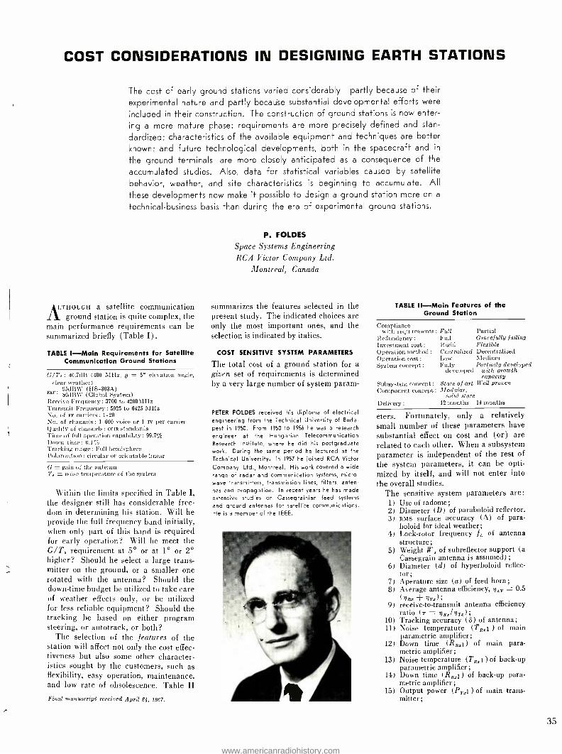
COST CONSIDERATIONS IN DESIGNING EARTH STATIONS
The cost of early ground stations varied considerably -partly because of their
experimental nature and partly because substantial developmental efforts were
included in their construction. The construction of ground stations is now enter-
ing a more mature phase: requirements are more precisely defined and stan-
dardized; characteristics of the available equipment and techniques are better known; and future technological developments, both in the spacecraft and in
the ground terminals, are more closely anticipated as a consequence of the
accumulated studies. Also, data for statistical variables caused by satellite
behavior, weather, and site characteristics is beginning to accumulate. All
these developments now make it possible to design a ground station more on a
technical- business basis than during the era of experimental ground stations.
A.THOUGH a satellite communication ground station is quite complex, the
main performance requirements can be summarized briefly (Table I) .
TABLE 1 -Main Requirements for Satellite Communication Ground Stations
G /T,: 40.7dB (400 MHz, g = 5° elevation angle, clear weather)
ear; 95dBWV (HS -303A) 89dB)V (Global System)
Receive Frequency: 3700 to 4200MHz Transmit Frequency: 5925 to 6425 MHz No. of aF carriers: 1 -20 No. of channels: 1 -600 voice or 1 Tv per carrier Quality of channels: CCIR standards Time of full operation capability : 99.7% Down time: 0.1% Tracking range: Full hemisphere Polarization: circular or orientable linear
G - gain of the antenna T.. noise temperature of the system
Within the limits specified in Table I, the designer still has considerable free- dom in determining his station. Will he provide the full frequency band initially, when only part of this band is required for early operation? Will he meet the G /T, requirement at 5° or at 1° or 2° higher? Should he select a large trans- mitter on the ground, or a smaller one rotated with the antenna? Should the down -time budget be utilized to take care of weather effects only, or he utilized for less reliable equipment? Should the tracking be based on either program steering, or autotrack, or both?
The selection of the features of the station will affect not only the cost effec- tiveness but also some other character- istics sought by the customers, such as flexibility, easy operation, maintenance, and low rate of obsolescence. Table II Final manuscript received April 24, 1967.
P. FOLDES
Space Systems Engineering RCA Victor Company Ltd.
Montreal, Canada
summarizes the features selected in the present study. The indicated choices are only the most important ones, and the selection is indicated by italics.
COST SENSITIVE SYSTEM PARAMETERS
The total cost of a ground station for a given set of requirements is determined by a very large number of system param-
PETER FOLDES received his diploma of electrical engineering from the Technical University of Buda-
pest in 1950. From 1950 to 1956 he was a research
engineer at the Hungarian Telecommunication Research Institute, where he did his postgraduate work. During the same period he lectured at the Technical University. In 1957 he joined RCA Victor Company, Ltd., Montreal. His work covered a wide range of radar and communication systems, micro- wave transmitters, transmission lines, filters, anten- nas and propagation. In recent years he has made extensive studies on Cassegrainian feed systems
and ground antennas for satellite communications. He is a member of the IEEE.
TABLE Il -Main Features of the Ground Station
Compliance with requirements: Full Partial
Redundancy : Full Gracefully failing Investment cost : Rigid Flexible Operation method : Centralized Decentralized Operation cost : Low Medium System concept : Fully Partially developed
developed with growth capacity
Subsystem concept : State of art Well proven Component concept : Modular,
solid state Delivery : 12 months 14 months
eters. Fortunately, only a relatively small number of these parameters have substantial effect on cost and (or) are related to each other. When a subsystem parameter is independent of the rest of the system parameters, it can be opti- mized by itself, and will not enter into the overall studies.
The sensitive system parameters are: 1) Use of radome; 2) Diameter (D) of paraboloid reflector. 3) RMS surface accuracy (A) of para-
boloid for ideal weather; 4) Lock -rotor frequency IL of antenna
structure; 5) Weight W, of subreflector support (a
Cassegrain antenna is assumed) ;
6) Diameter (d) of hyperboloid reflec- tor;
7) Aperature size (a) of feed horn; 8) Average antenna efficiency, rl,,y = 0.5
(gRz +nrs); 9) receive -to- transmit antenna efficiency
ratio (.r = nR.rl nTS); 10) Tracking accuracy (8) of antenna; 11) Noise temperature (TRul ) of main
parametric amplifier; 12) Down time (RRa1) of main para-
metric amplifier; 13) Noise temperature (TRz1 ) of back -up
parametric amplifier; 14) Down time (R;,1) of back -up para-
metric amplifier; 15) Output power (P,,:1) of main trans-
mitter;
35
www.americanradiohistory.com
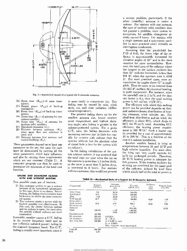
m
Fig. 1- Mechanical layout of a typical 85 -ft diameter antenna.
16) Down time (RT,i ) of main trans- mitter;
,17) Output power (P,,y2) of back -up transmitter;
18) Down time (Rrz2) of back -up trans- mitter;
19) Down time (RAH) of antenna for syn- cronous satellite;
20) Down time (RA,,) of antenna for medium orbit satellite;
21) Threshold extension (L); 22) Distance between antennas (KA)
when more than one antennas is used; and
23) Distance between first antenna and control building (K0).
These parameters depend on at least one parameter in the set; the value for each must be determined by varying all the other parameters which have influence, and also by varying those requirements which are not constant (Table I) . A computer program can then be used to determine the minimum of the total cost function.
is more costly to compensate for. This fading may be caused by rain, wind, snow, ice, and solar radiation (differ- ential temperature) .
The greatest fading shows up for the smallest antenna size, lowest receiver noise temperature, and highest eleva- tion angle; also fading is greater in the radome -protected system. For a given G /T, ratio, the fading decreases with increasing antenna size (a little less rap- idly for systems with radome than for systems without, but the absolute value of signal fade is less for the system with no radome) .
In the fading calculations of the sys- tem without radome, it was assumed that the total time per year when the ice on the antenna is more than 1.5 inches thick, or the snow is more than 5 inches deep, is restricted to 8 hours. For stations with two antennas, this would not present
a serious problem, particularly if the other (standby) antenna is under a radome. For stations with one antenna, the care of medium orbit satellites does not present a problem, since system in- terruptions for satellite changeover al- ready exceed 8 hours. For stations with a single antenna and a syncronous satel- lite (a more practical case) virtually no interruption is tolerated.
Assuming that the paraboloid has F/D of 0.42, the lower edge of the re- flector is approximately horizontal for elevation angles of 30° and is the most sensitive for snow accumulation. How- ever, the total area of the reflector where the tangent to the surface encloses less than 45° with the horizontal, is less than 831 ft, when the aperture area is 6318 ft'. For most practical cases, snow ac- cumulation for angles above 45° is negli- gible. Then the snow or ice removal from the 831 ft'. surface, by electrical heating, is quite inexpensive. For instance, when the snowfall rate is 2 in /h, and the den- sity factor is 0.1, then the total melting power is 9.9 cal /sec (41W /ft2).
The efficiency with which this melting power can be provided depends on ther- mal radiation losses, distribution of heat- ing elements, wind velocity, etc. For ideal heat distribution and no wind, the efficiency is about 80 %, which drops to 66% for 20 mi /h wind. Assuming 41% efficiency. the heating power require- ment is 100 W /ft.' Such a heater can be provided for a cost of approximately 10 to 20$ /ft. This is a fraction of the cost of a radome installation.
Another weather hazard is icing at temperatures between 26 and 32 °F and high relative humidity. For most sites, the icing rate very rarely exceeds 0.1 in /h for prolonged periods. Therefore, 50 W /ft heating power is adequate for this purpose. If the heating facilities for de -icing are restricted for the inner part of the reflector, defined by level lines within which half of the total RF power is
UPLINK AND DOWNLINK FADING WITH AND WITHOUT RADOME
Two possible cases are of interest: 1) The customer prefers to use a radome
because of its operational advantages. In this case, there is no choice. Never- theless, the fading characteristics must be known, to obtain the most economi- cal system.
2) The customer wants a system with the highest possible cost effectiveness. In this case, the choice between radome and no radome is open; for most sites, the systems without radomes are more economical.
Generally, weather causes a G /T, fading in the receive frequency band and an ERP (effective radiated power) fading in the transmit frequency band. The G /T, fading is usually more important, since it
TABLE Ill- Mechanical Data of a Typical 85 -ft Diameter Antenna
Component Weight (1031ós.
Distance from pivot NZOlnent
) (ft) (103 ft. lbf) Reflector
area (ft2)
Weight /Area (lbs /ft2)
Feed Cone Quadnlpod Hyp. Basic panels Extra panels Basic trusses Extra trusses Subtotal Shell
Counterweight El. structure Az. structure Ant. structure
5.3 10.0
0.55 10.7 - 54.3 -
120.000
120 000 320,850 212.150 533.000
20.58 109.074 31.08 310.080 46.58 25.619 15.76 168.632
13.0 705.9
1319.305 -1.97 -60.695
-10.48 -1258.610
NOTES: D = 85 ft. A m 0.037 in. RMS
ft = 2.25Hz Hyp. Support : Steel Quadrupod
6140
6140
1.74
8.84
10.58
Cost ($) $ /lb
740.000 1.39
36
www.americanradiohistory.com

TABLE IV- Calculated Lock Rotor Frequencies for Various Practical Cases
f Case 1 2 3 4
kHz 2.47 2.47 2.47 2.25 2.14 1.91
D(ft) d lgd. d,.o do.r do.t m
.5 (in.) 0.037 1.6 0.040 0.050
1.0 0.1 Variable
0.1 0.037
0.1 0.040
0.1 0.050
85 1 0 2.47 2.35 2.10 2.47 2.47 2.25 2.14 1.91 90 1.0588 .02472 1.0953 1.0407 1.0055 2.25 2.14 1.91 2.37 2.45 2.23 2.12 1.89 95 1.1176 .04828 1.1945 1.0810 1.0110 2.06 1.97 1.75 2.28 2.44 2.22 2.11 1.88
100 1.1764 .07056 1.2987 1.1205 1.0163 1.90 1.81 1.62 2.20 2.43 2.21 2.10 1.87
concentrated, then an additional 26% of the paraboloid reflector (in the upper half) has to be equipped with (half - density) heaters.
The operational cost of such a heater facility is only a fraction of the opera -
tional cost of the radome. This example is typical of problems related to weather protection of large antennas without radomes.
ANTENNA SYSTEM COST CONSIDERATIONS
Before any cost analysis of the system can be made, the cost of the antenna sys- tem must be determined as a function of its diameter, surface accuracy, lock -rotor frequency, tracking accuracy, and design of the subreflector support. The situation can be analysed on a typical existing 85 -ft. diameter design; Fig. 1 shows the basic layout of the antenna. The break- down of the weight and overturning moments are indicated in Table III.
One of the factors influencing the cost of the antenna is the type of support for the subreflector. Fig. 2 indicates the relative cost variation of the above an- tenna with a monopod support in an open environment for no -wind conditions. Three different design conditions were assumed for the accuracy of the reflector: Case 1: Practical design, in which the sur-
face accuracy, i, varies according to the curve given in Fig. 2, as the diameter varies. This surface accuracy variation is obtained without a reinforcement of the back -up structure. The "practicality" in this design means that only the counter- weight, hyperboloid support, and surface panels beyond the 85 -ft. diameter, are changed relative to Table III. The limit for this design is about 95 ft.
Case 2: "Ideal" design, with varying A. This case is similar to case 1, but the structure is redesigned to compensate for varying weight conditions. Below 95.5 ft., the structure is lighter; above that limit it is heavier than the "practical" design.
Case 3: Ideal design with constant A. The selected values are: 37, 40 and 50 -r). In each case calm weather was assumed. Fig. 3 shows the relative variation of cost of an inflated radome versus antenna diameter, if this protection is added to the system.
From Table IV, it can be seen that the monopod results in a superior lock -rotor frequency. Generally, the lock -rotor frequency decreases with the diameter, because of the increase of the structural
weight, but with a light hyperboloid sup- port the lock -rotor frequency can be kept above 1.8 Hz. This frequency is adequate for tracking medium altitude and syncronous satellites.
MINIMUM COST FOR A GIVEN G /T, RATIO
The two most important components in the cost, to obtain a given G /T, ratio, are the antenna structure and the low - noise preamplifier.
Assuming 500 -MHz receiver band- width, the parametric amplifiers are the most practical preamplifiers to achieve low noise temperatures. Generally, the cost of a parametric amplifier increases rapidly by decreasing noise tempera- tures; the necessary cooling machine be- comes more complex, less reliable, and more expensive to maintain. There are at least four different types of amplifiers for the various temperature ranges. Their characteristics and price range are ex- hibited in Fig. 4.
The indicated cost figures refer to the currently required small quantities. A cost improvement of an order of two is expected in the coming five years as larger quantities of standardized types of these amplifiers will be required. The basic character of the curve on Fig. 4, however, is not expected to change dur- ing the next 5 year period.
Using Figs. 2, 3, and 4, the cost varia- tion of the antenna structure, plus para- metric amplifiers, versus antenna diam- eter can be calculated (Fig. 5) . The same figure indicates the variation of G /T, and lock rotor frequency.
Fig. 6 indicates the cost of the struc- ture plus parametric amplifiers for con- stant G /T, ratios. It can be seen that for each G /T, ratio, there is an antenna diameter and receiver noise temperature, which results in minimum cost. With increasing G /T, requirement, this mini- mum shifts toward larger antennas and smaller noise temperatures. For the range of 40.7dB < G /T, < 42.7dB, the optimum antenna diameter is 91.5 ft. < D < 99.5 ft., and the receiver tempera- ture is 45 °K > T51 > 22 °K. The "opti- mum" receiver noise temperature falls within the range of helium gas type cooling machines.
On the basis of previous results, it is possible to predict the cost of a given increase of the G /T, ratio under opti- mum conditions. The approximate dif- ferential increases in cost needed to obtain 1dB improvement in G /T, are indicated in Table V.
TABLE V -Cost of 1 -dB GIT, Increase for Optimum Conditions
(Rohr dish, aluminum quadrupod)
Increase from 40dB 41dB 42dB
to 41dB 42dB 43dB
Cost (103$) 38 74
139
Ave. 84
DETERMINATION OF OPTIMUM FEED SYSTEM
Excluding the possibility of focal point feeds as operationally inconvenient, and horn reflectors as costly, the only remain- ing type of feeds is the Cassegrainian. In this category, three main types of feeds are developed, with increasingly better characteristics. These are:
1) One horn, single -mode feeds; 2) One horn multimode feeds; and 3) Multihorn multimode feeds.
The most important single characteristic related to the feed is the overall average antenna efficiency nAv = 0.5 (nR + nr.), where n5 and n, are the average antenna efficiencies for the receive and transmit band respectively. Fig. 6 shows the cost of these feeds versus their an- tenna efficiency. The generalized curve between these discrete points is some- what academic, but it predicts the gen- eral tendency for the cost of antenna efficiency. Using the previous results, the differential cost variations versus nAv
can be calculated. Fig. 7 shows the change of cost for the 100 -ft dish, alu- minum quadrupod, and TRs1 = TR., = 22 °K. The curve predicts, for this case, an optimum value of -2.80dB for nAy.
The closest existing feed system is the 1 -horn multimode feed, with 2.64dB.
COST OF THE EFFECTIVE RADIATED POWER
For the requirements given in Table I, the cost of the effective radiated power is determined by the antenna gain (diam- eter of antenna) , the reliability of the transmitter system, and the location of power amplifiers relative to the feed.
Fig. 8 shows the variation of cost for antenna diameter, D = 105 ft. and for ground located transmitters, assuming 2.5 -dB transmission line loss between the transmitter tube output flange and the antenna feed input flange. The cost of transmitted power was calculated for the condition that output power of the tube is sufficiently below saturation, to keep third order products below -20dB
37
www.americanradiohistory.com

CKI
85
RMS -' T 10kIN
ACCURACY X
NO WIND
r .°
.
- 3 . A-,
1:F737.r;MIIII , lTIE+ El v
- I.: 'ilaAlo :,uw ̀At:.i1r :7f(S6
- , ///, t'' .dl.-ul.l/A -
1 Ç. = D. .
1
( / / I( / I /I 1
i I
........r..
i I 1
- I I
750
700
90 95 100 DFr.
S5
50
45
Fig. 2 -Cost and RMS surface accuracy of an- tenna structure versus diameter (with mono - pod support).
for 2- carrier operation. Two types of transmitters were assumed:
1) "Modular" type of transmitter, in which 1.88kW, 3.53kW, and 6.63kW useful power can be obtained by the paralleling of two, four, and eight 1kW tube modules, respectively, with a com- bination efficiency of 94% (such a 1kW tube is not available at the moment).
2) Single tube approach for the 1kW, 2.8kW (Siemens), 5kW (Hughes) case
Fig. 8 shows that the cost of transmitter power increases more than linearly with the level of the required ERP and the variation increases by decreasing the antenna diameter.
OPTIMUM ANTENNA EFFICIENCY RATIO FOR THE RECEIVER AND
TRANSMITTER BAND
From the cost variation of G /T, and cost of ERP (Fig. 8) the optimum value of the T = 7R.z /v77x ratio can be calculated.
Fig. 9 indicates the differential cost
Fig. 5 -Cost, G /T, and fl versus antenna diameter (O = 5 °, TA = 36 °K)
Cki
ID
- COST STRUCTURE 8 y
f
fF"J., . .
-- vela. 40
= \.
tFSA(
h°4 RV IeIüi
El 900
8
7
38
1
40
fM
2.4
22
.8
CKS
4
_
/ 180S_ --í __LABO=-
INSTALLA
200
100
90 95 100 DFT
Fig. 3 -Cost of inflated type radome versus antenna diameter.
variation as a function of 7- for ERP = 95dBw, D = 100 ft., and v,V = 2.65dB. (1 -horn multimode feed) .
COST OF THRESHOLD EXTENSION
To provide adequate fading margin in the receiving system, at an economical cost, the threshold level of the demodu- lator must be extended relative to the level (10dB ) achievable by a standard FM demodudator. Various methods have been recommended for this purpose (FM feedback, phase lock, IF bandwidth re- duction) , which, however, have one com- mon characteristic: the cost of such a demodulator increases with the number of required RF carriers, with voice chan- nel capacity, and with the required threshold improvement (A L) .
Fig. 10 shows the variation of cost for 1 -dB threshold improvement versus the number of voice channels (n) for the number of RF carriers of N = 2, 6, 10
Fig. 6 -Cost of feed system versus average antenna efficiency.
CKi
ISO
10
50
_
-
- -
'FEED* RAL
DU
FED SUH,EFLECTOR
INCLUDES :
ATNR SOURCE
KE 8 TRAO(NG HOUSING
TRACKING) COM
CHANNEL 8H
FUERS
'AV 2R% QTY
_ FIVE DRN, MULTIMODE FEED
IN FM BAND
- ONE HORN, MULTIMODE FEED
_ONE HORN, 31110.E MODE FEED
- -35 -10 1I db I III 11 19
I 11 1
50 80 70 SAV %
200
150
00
50
B 500 MIR G 70db (811M POST AMP)
7(5D HFlIL59 COOLED
MELMA GAS COOLED
ROOM TEMPERATURE 0 50 I 1 I I 100
I I I I
ISO' Ri %
Fig. 4 -Cost of parametric amplifier versus receiver noise temp. (instantaneous band- width: 3.7 to 4.2 GHt, post amp. included).
and 20. The cost estimate is based on the development and production costs of the equipment. Fig. 10 indicates also the theoretically expected maximum possible threshold extension, A L. The curves are prepared for the ideal case, when the complexity (and cost) of the threshold - extending device is adjusted according to the required amount of extension and channel capacity. Again this is some- what hypothetical, but as more different modules will be developed for the various requirements, the practice will be closer to this "optimum" provision of extension. It can be seen that for large numbers of carriers, and for large channel capacities, the cost of threshold extension is quite large. For instance, for an N = 6, n = 600 system, with a total improvement of 0 L = 3dB, the cost of the extension system is $259,000, or $86,500/dB. This is about the same as the cost of 1dB through G /T, improvement.
Fig. 7- Incremental cost variation of antenna structure and feed versus vev for TR11 = Tsx, =22 °K and D (nominal) = 100 ft.
IDO
z 50
_
0 V f]
A
5 MORN,
-
_MULTIMa I I I l
1 MORN, SINGLE
t*V-29db(ptimkw I 1 1 t
MODE
till 11 -3.0 -4.0 nAV
www.americanradiohistory.com

cKS
300
100
e101eB-23S9Tab , Di00FT Q 2 Soy (FOR GROUND LOCAgNI -IKW /A0011LES WITH -SSTMpr IKW /AODl1LES *ITN F1K1 STMaBT o SKW DUMB /ACCULES SWTIT
0 2DKW (SIEMENS MODULES WITH FT. -!m STANDBY
Fig. 8-Cost of transmitter power.
To illustrate the sensitivity of the sys- tem cost to the cost of the antenna struc- ure, cost of power amplifier, and cost of FMFB receiver, the variation of the cost of these equipments versus antenna di- ameter is plotted in Fig. 11. The condi- tions for this figure are indicated in Table VI.
TABLE VI- Typical Conditions for a Practical RF System
Tres = 22 °K Tars = 60 °K Pr. = 95dBm (in more than 90% of time) Prs: = 92dBm (in more than 10% of time)
N =2 n = 300 and 600
Hyperboloid support : Monopod No radome
B =5°
It can be seen from Fig. 11 that by ideal (proportional) design of the three subsystems which influence the selection
Fig. 11 -Cost of antenna structure, transmit- ters, and FMFB versus antenra diameter for n - 300 and 600. ct
1500
1000
.INT U?O9 __ r b _ -
1
2 ! Tab Fig. 9- Differential cost variation of antenna structure paramps and transmitter versus r = n,2: /TT. (ERP = 95 dBw, D = 100 ft, 7/AV = 54.596)
of antenna diameter, the total cost can be minimized around D = 93.5 ft.
By the use of the curves given pre- viously, a series of cost tables can now be prepared for various combinations of the parameters in Table VI. These com- binations have to be restricted to an ac- ceptable standard of reliability (down time) consistent with the 99.7% overall operational reliability specified in Table I.
CALCULATION OF COST
FOR OPTIMUM CONFIGURATIONS
Fig. 12 indicates the variation of the approximate cost of a voice channel (C) as a function of the total voice -channel capacity V of the station. It can be seen that for the small user (V = 48 chan- nels), the cost per channèl is very large ( minimum $60,541) . Nevertheless, this cost may still be attractive, if there is no other way for reliable communication. For the medium user (V = 240 chan- nels), the installation cost per channel is very economical ($11,681, minimum, with feed cone mounted transmitter, without reflector heater, and with two simultaneous carriers). Finally, for a very large user, V = 1200, the cheapest system costs $2606 /channel. A more re- fined system (with program steering in- cluded), costs $2741 /channel, and a deluxe version (with radome), $31001 channel.
CONCLUSIONS
On the basis of the previous analysis, the following conclusions can be made:
1) With the exception of very severe climatic conditions, the use of radome is not economical for commercial satellite communications. For identi- cal performance, a system with radome cost about 13.5% more than a system with antenna heaters.
2) The limit of the present antenna de- signs can be expanded to 100 -ft. diameter.
ci
R
Fig. 10 -Cost of FM threshold improvement and maximum possible improvement versus number of voice channel, p.
3) A pre- stressed steel hyperboloid sup- port Imonopod) offers a 0.2dB im- provement in the G /T, ratio, and an associated saving in the structure. Hyperboloid positioning mechanism virtually disappears in this structure.
4) For channel capacities /carrier of 300, or more, the optimum antenna diam- eter is above 90 ft. To provide future growth and room for lower cost re- ceiver front ends, an antenna diam- eter of 95 ft. should be selected.
5) The optimum type of feed system is the single horn, multimode design. The system economy does not tolerate either a simpler or a more compli- cated feed concept.
6) The optimum ratio for the receive -to- transmit frequency -band antenna effi- ciency is 2.52dB.
7) A modular type of transmitter is required to make an optimally adap- table system to the various require- ments. For this purpose, the develop- ment of a TWT with 1400 -W saturated output is necessary with an opera- tional level of about 1000 to 1100W.
8) It is more economical to locate the transmitter in the feed cone than on the ground, but very high reliability must be achieved before customers will accept such a location.
9) The back -up transmitter can be -3dB, relative to the main transmit- ter, without affecting overall loop per- formance, if it is operated only in a maximum 10% of the time.
10) The main receiver front end has to be a helium -gas -cooled paramp for sta- tions with 40.7 -dB G /T, ratios.
11) The cost of FMFB receivers represents a very substantial part of the station for a large number of channels. The development of FMFB receivers, in which cost can be made proportional to the number of voice channels and required threshold improvement, could result in a substantial saving in the cost of the total station.
12) There is about one -million- dollar dif- ference between the price of the cheapest and most expensive stations, among the analyzed cases.
13) The cost per channel varies between very wide limits I from about $60,000 for a 48 channel equipment, to about $3,000 for a 1200 channel equipment).
39
www.americanradiohistory.com

THE WIDEBAND COMMUNICATIONS SYSTEM
OF CANADA'S MILL VILLAGE
COMMUNICATIONS SATELLITE EARTH STATION
This paper describes the transmitting and the receiving equipment comprising the Wideband Communications facilities of Canada's communications- satellite Earth Station at Mill Village built for the Department of Transport by RCA Victor Company, Ltd. Various systems aspects, noise, interface requirements, and equipment locations are also discussed.
CANADA and the United States agreed 1963 to participate in a space
communications experiment using a pro- posed NASA satellite to be known as the Advanced Technological Satellite (ATS). General characteristics of this experimental space link for telephony signals would be sse transmission in the up -path (ground to satellite), and PM transmission in the down -path (satellite to ground) , while for television signals they would be FM for both up -path and down -path.
Canada's contribution to the experi- ment was the development, construction, and operation of a communications - satellite earth station in the eastern part of her territory, forming one terminal of the experimental system. Canada's De- partment of Transport was authorized to proceed with the station.
EARLY PLANNING BY RCA VICTOR, LTD.
RCA Victor Company, Ltd., in Montreal, Quebec, was engaged in a consulting capacity for the preparation of system parameters and specifications, and assis- tance in site selection. A contract was awarded for the project management, system engineering, integration, and
This work was done under Contract Number 72116, File No. 6801 -663 Department of Transport, Ottawa, Ontario. Final manuscript received April 24, 1967.
40
JOHN A. STOVMAN, Ldr. RF Equipment
Aerospace Engineering RCA Victor Company, Ltd.
Montreal, Canada
contracting responsibilities for the an- tenna, radome, servo and tracking sys- tem, transmitters, receivers, and low - noise amplifier. The Department of Transport acted as the design authority and retained responsibility for building, services, multiplex, and boresight.
The location chosen for Canada's earth station was near Mill Village, Nova Scotia, some 9 miles from the Atlantic ocean. This site is relatively free from interference from radio relay systems and aircraft, and is reasonably close to a major communications terminal.
While the Mill Village station was under construction, the launch date for ATS was delayed due to the increasing diversity of the experiments.
Meanwhile, the Communications Sat- ellite Corporation, (CoMSAT) obtained permission to own and operate commer- cial satellites, placed the "Early Bird" satellite into orbit, and leased Andover (Maine) earth station for the American terminal of its operation. Attention focused on the possible use of Mill Vil- lage as a second North American com- mercial terminal sharing the duties with Andover. Expediency and time would not permit the construction of a second earth station for this purpose, therefore the experimental station would have to be used until it could be relieved by
JOHN A STOVMAN received the BA Sc from the University of British Columbia in 1953; in 1964, he received a graduate diploma from McGill Uni- versity. From 1953 to 1959, Mr. Stovman was with the Canadian Broadcasting Corporation where he worked on the design, installation, and checkout of Television Studios. In 1960, he joined RCA where he worked on a study of radar systems in
the ECM environment. He also worked on the study and development of a rapid checkout sys-
tem for gun fire control systems. Since 1963, Mr. Stovman has been senior engineer in charge of wideband communications for the DOT ground station. He has also participated in studies of atmospheric losses, space communications systems, and low -noise receivers and in preparation of spe- cifications and proposals for future ground sta- tions. Mr. Stovman is a member of the IEEE and the Corporation of Engineers of Quebec.
www.americanradiohistory.com
Satellite
TABLE 1- Initial Operating Frequency Capability for Mill Village
Transmit Frequent Telephony,
Tv Video
es (MHz)
Tv Audio
Receive Frequent Telephony,
Tv Video
es (MHz)
Tv Audio
Beacon Fre- quencies (MHz)
ATS 1) 6212.094 Subcarrier 4119.599 Subcarrier 4135.946 (NASA)
2) 6301.050 Subcarrier 4178.591 Subcarrier 4195.172
Early Bird 1) * 8389.97 6400.97 4081.00 4092.00 4104.14 (COMSAT)
2) ** 6301.02 6290.02 4160.75 4149.75 4137.86
*Used in North America ** Used in Europe
another Canadian station. The capabil- ity for handling signals through Early Bird were therefore added to Mill Vil- lage requirements while the station was under construction. Thus, Mill Village had a dual requirement from the outset, and this situation is reflected in many of the system design details and equip. ment complements.
BASIC STATION CONCEPT
Conceived with an experimental view- point, the communications capabilities of Mill Village were to be kept flexible. Primary services would be for Early Bird and ATS, as reflected in Table I. However, the earth station design, through the addition of relatively inex- pensive and simple hardware, must be capable of operation at other frequen- cies. Requirements for the initial equip- ment complement were as follows:
1) Transmit and receive up to 1200 tele- phony channels with a performance meeting ccIR recommended standards;
2) Transmit and receive 525 line mono- chrome television signals with a per- formance meeting CCIR recommended standards;
3) Transmit both FM and SSB signals with powers up to 10 kilowatts average any- where in the 5.925- to 6.425 -GHz common -carrier band;
4) Receive two FM or PM carriers simul- taneously, at power levels as low as -100 dBm anywhere in the 3.7- to 4.2 -GHz common -carrier band;
5) Achieve a dry weather system noise temperature of 65 °K at an antenna elevation angle of 7.5° above the horizon; and
6) Track any present or future satellite
TABLE II- System Thermal Noise- Temperature Budget
(Antenna Elevation Angles 71/2° Above Horizon)
Contributor Noise Temp. ( °K) Atmosphere (dry weather) 17
Dry Radome (absorption and scattering) 9
Antenna Sidelobes 9
Feed System and Waveguide 17
Parametrie Amplifier 13
Other Amplifiers 1
Total System Temperature
in an orbit appropriate for communi- cations.
For convenience in the distribution of baseband signals throughout the station, the following baseband signal standards were selected:
telephony: -20 dBm test tone across 75 ohms, unbalanced;
video: 1 volt peak -to -peak, positive going, across 75 ohms unbalanced; and
audio: +9 dBm (maximum signal) across 600 ohms, balanced.
NOISE CONSIDERATIONS
Noise is a basic limitation in all systems. In communications systems, noise is gen- erally classified into two types:
Thermal noise which is generally pro- duced by the physical temperature of am- plifiers and lossy elements such as wave - guides, cables, etc;
Intermodulation noise which is produced after demodulation by non -linear circuit elements and uncorrectable group delays in transmission elements.
Most thermal noise originates in the signal processing stages of the receiving system, while intermodulation noise may result from deviations in the equipment parameters almost anywhere; however, the latter is usually more prominent in the frequency limiting circuitry such as filters, amplifiers, and the transmitter power tube.
Since the performance specifications for communications links are given as noise aggregates, more thermal noise can be tolerated for economic reasons than intermodulation noise. It is very
TABLE Ill- Design Objective for the Intermodulation Noise Budget
(300 channel) Contributor Noise (picowatts)
FM Exciter 200
Receiver (FM Path) 330 Power Amplifier 80 Parametric Amplifier 50
Feed (4 GHz path) 25
Feed (6 GHz path) 25
Baseband Link 50
Total Noise 500 65 Equivalent Noise Power Ratio : 44.1 dB
expensive to provide additional ERP
capability in satellites. Thus, 3/4 or more of the permissible 10,000 picowatts of psophometrically weighted noise al- lowed by the CCIR standards for tele- phony is usually allowed for the thermal - noise contribution ; the balance is for intermodulation noise and is shared by both the satellite and earth -based equip- ment non -linearities.
Signal power radiated earthwards by present generation satellites is quite modest; at the earth station, the power received by the antenna in the order of -90 to -100 dBm. Since wide -index FM is the rule, power is spread out over a broad -signal spectrum. The useful recovery of these signals is a difficult task and requires special low -noise tech- niques and equipment.
To prevent thermal noise contribu- tions from exceeding the allowance, sys- tem noise temperature must be kept below 65 °K under dry weather condi- tions. Table II lists the contributors to the system noise temperature for the mini- mum antenna elevation angle of 71/2°
above the horizon. This very low system temperature was achieved by:
1) Reducing the antenna side -lobe pickup by careful design;
2) Reducing the feed system attenuation and mismatch losses to very low levels, and
3) Physically cooling the first RF ampli- fier in the receive path.
The first two of the above techniques are outside the scope of this discussion; the third is appropriate. The first RF ampli- fier, a parametric amplifier, was cooled to 4.2 °K in a closed -cycle cryogenic refrigerator. A parametric amplifier, rather than a maser, was chosen because of its relative simplicity and its wide instantaneous bandwidth. When cold, the amplifier produced about 13 °K of the measured 65 °K noise temperature.
For intermodulation noise the design goal was set at 500 picowatts or less so that future requirements would not be compromised. Table III summarizes the designed upper level of performance of the station with respect to intermodula- tion noise contributions from the various sources of non -linearities.
EQUIPMENT LOCATIONS
The station consists of a central -control building and an antenna structure pro- tected by a radome and separated from the control building by about 1200 feet. Thus the antenna beam clears the top of the control building when the antenna elevation angle is as low as 3° above the horizon. More antennas may be added to the complex as long as the spacing
41
www.americanradiohistory.com
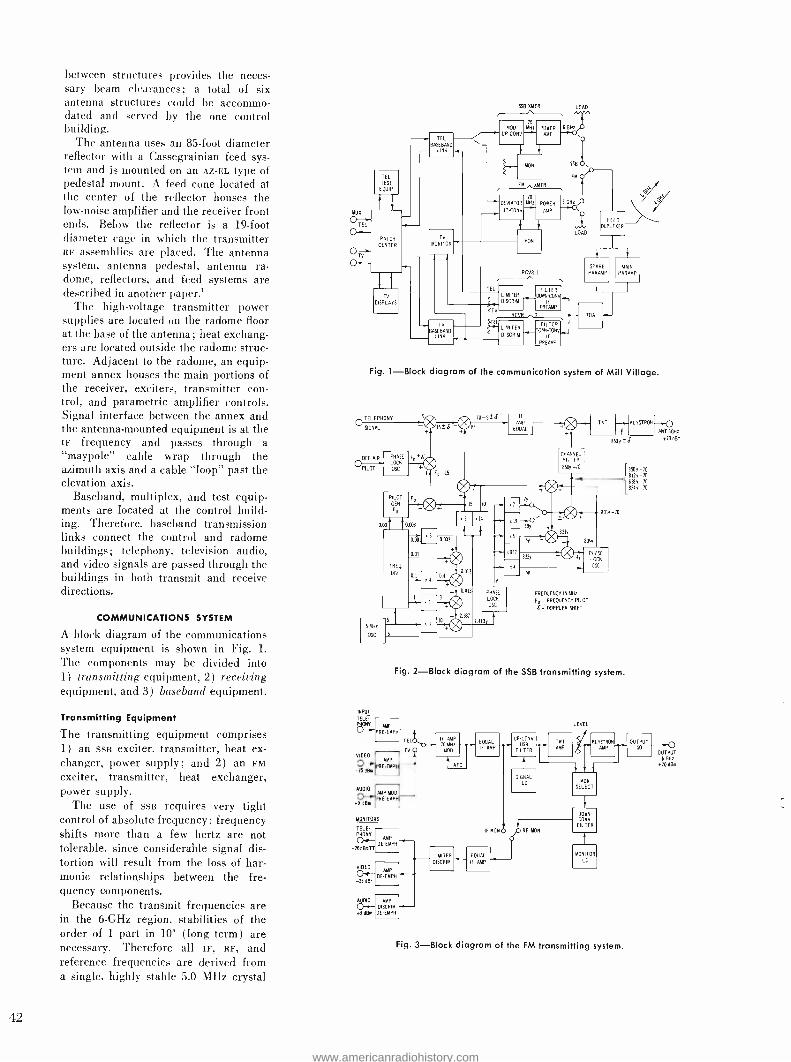
between structures provides the neces- sary beam clearances; a total of six antenna structures could he accommo- dated and served by the one control building.
The antenna uses an 85 -foot diameter reflector with a Cassegrainian feed sys- tem and is mounted on an Az -EL type of pedestal mount. A feed cone located at the center of the reflector houses the low -noise amplifier and the receiver front ends. Below the reflector is a 19 -foot diameter cage in which the transmitter RF assemblies are placed. The antenna system, antenna pedestal, antenna ra- dome, reflectors, and feed systems are described in another paper.'
The high- voltage transmitter power supplies are located on the radome floor at the base of the antenna; heat exchang- ers are located outside the radome struc- ture. Adjacent to the radome, an equip- ment annex houses the main portions of the receiver, exciters, transmitter con- trol, and parametric amplifier controls. Signal interface between the annex and the antenna -mounted equipment is at the IF frequency and passes through a "maypole" cable wrap through the azimuth axis and a cable "loop" past the elevation axis.
Baseband, multiplex, and test equip- ments are located at the control build- ing. Therefore, baseband transmission links connect the control and radome buildings; telephony, television audio, and video signals are passed through the buildings in both transmit and receive directions.
COMMUNICATIONS SYSTEM
A block diagram of the communications system equipment is shown in Fig. 1.
The components may be divided into 1) transmitting equipment, 2) receiving equipment, and 3) baseband equipment.
Transmitting Equipment
The transmitting equipment comprises 1) an sss exciter, transmitter, heat ex- changer, power supply; and 2) an FM
exciter, transmitter, heat exchanger, power supply.
The use of SSE; requires very tight control of absolute frequency: frequency shifts more than a few hertz are not tolerable, since considerable signal dis- tortion will result from the loss of har- monic relationships between the fre- quency components.
Because the transmit frequencies are in the 6 -GHz region, stabilities of the order of 1 part in 10' (long term) are necessary. Therefore all IF, RF, and reference frequencies are derived from a single, highly stable 5.0 MHz crystal
42
TEL TEST
EQUIP
f1
PATCH
CENTER
DISPLAYS
TEL
BASEBAND I-. LINK
TV
MONITOR
SSB XMIR LOAD
' MOD 1,11 POWER 6 G UPN AMP AMP
NON SSA
FM Or-
UP-CON
FM %NTR
70
DEVIATOR MH: POWER 6 GH:
V AMP ^
i Y
TV
~BASEBAND LINN _
AGIR I
LOAD
EL FILTER LIMITER OOY
DISCRIM - F
-*-
TV PREAMP
RC 2
F ,FILTER
. 67-
L
DISIMITERIM
R ACONVI_
C IF PREAYP
F ED
DUPLEXER
SPARE
PAR AMP
TON
MAIN
PAR AMP
Fig. 1 -Block diagram of the communication system of Mill Village.
TELEPHONY
SIGNAL
D -S+ -d TAT KLYSTRO
ECAIAL
OFF AIR PHASE FRIG LOCH
ILOT USC + BEOy -70 230y-70 AItY -70
5
8318y -70 82ÁY-70
834 -70
0.03
INPUT
FREQUENCY IN MHz
FA - FREQUENCY PILOT
g- DOPPLER SHIFT
Fig. 2 -Block diagram of the SSB transmitting system.
ANT 6GHz
OBAo
TELE
Cr
VIDEO
E-E
PRE EMPI
SE
TV
LEVEL
r OUTPUT-^O
6 GH:
IF AMP
70 MHz
MOD
E DUAL IP AMP
USA
I
UPCONO TNT AMP
KLYSTRON OUUT ISO
TP
PMP
IO ASH RE-EMI" t AFC 70 aAm
SIGNAL
AUDIO LO MON
SELECT AMP NOD .
PRE -EMPI +9 013m
MONITO S
DOWN- COMA
FILTER TELE RF EON IF MONO
AMP PHONY
-20a&eTT OE -EMPI
LIMITER
DISCRIM
EQUAL
IF AMP
MONITOR
LO
AMP AIDED
-n dam DE-EMPH
AUDIO
off- AMP
DISCRIM
9d8m DE-EMPH
Fig. 3 -Block diagram of the FM transmitting system.
www.americanradiohistory.com
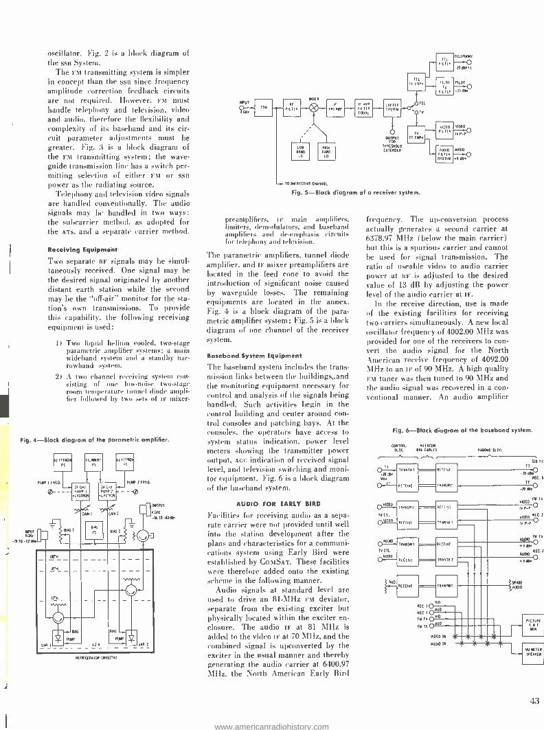
oscillator. Fig. 2 is a block diagram of the SSE System.
The FM transmitting system is simpler in concept than the SSE since frequency amplitude correction feedback circuits are not required. However, FM must handle telephony and television, video and audio, therefore the flexibility and complexity of its baseband and its cir- cuit parameter adjustments must be greater. Fig. 3 is a block diagram of the FM transmitting system; the wave - guide transmission line has a switch per- mitting selection of either FM or ssB power as the radiating source.
Telephony and television video signals are handled conventionally. The audio signals may be handled in two ways: the suhcarrier method. as adopted for the ATS. and a separate carrier method.
Receiving Equipment
Two separate RF signals may be simul- taneously received. One signal may be the desired signal originated by another distant earth station while the second may be the "off -air" monitor for the sta- tion's own transmissions. To provide this capability, the following receiving equipment is used:
1) Two liquid helium cooled, two -stage parametric amplifier systems: a main wideband system and a standby nar- rowband system.
2) A two channel receiving system con- sisting of one low -noise two -stage room temperature tunnel diode ampli- fier followed by two sets of IF mixer-
Fig. 4 -Block diagram of the parametric amplifier.
FrLYSTROH
PS
POE I PRAO
INPUT WE
-ro TO 107 On
FILAIENT PS
P GH: PUMP :
NLYSTROH
AS 1
CANI
LYSTRON PS
PUW 1 FREO.
N -29 PUIV?
ALYSTRON
BIAS
GANZ
BIAS
t- OUTPUT
! MT - -96 T0 d3 MBR
6'N
IYN
VAR 1
BAS
PUMP
BIAS 1 1
PUMP
t1;,
VAR. 2
REFRIGERATOR CRYOSTAT
TO Ina RECEIVE CHANNEL
OUTPUT FOR
THRESHOLD
EXTENDER
Fig. 5 -Block diagram of a receiver system.
preamplifiers, IF main amplifiers, limiters, demodulators, and baseband amplifiers and de- emphasis circuits for telephony and television.
The parametric amplifiers. tunnel diode amplifier, and IF mixer preamplifiers are located in the feed cone to avoid the introduction of significant noise caused by waveguide losses. The remaining equipments are located in the annex. Fig. 4 is a block diagram of the para- metric amplifier system; Fig. S is a block diagram of one channel of the receiver -,vstem.
Baseband System Equipment
The baseband system includes the trans- mission links between the buildings and the monitoring equipment necessary for control and analysis of the signals being handled. Such activities begin in the control building and center around con- trol consoles and patching bays. At the consoles, the operators have access to system status indication, power level meters showing the transmitter power output, Act indication of received signal level, and television switching and moni- tor equipment. Fig. 6 is a block diagram of the baseband system.
AUDIO FOR EARLY BIRD
Facilities for receiving audio as a sepa- rate carrier were not provided until well into the station development after the plans and characteristics for a communi- cations system using Early Bird were established by ComSAT. These facilities were therefore added onto the existing scheme in the following manner.
Audio signals at standard level are used to drive an 81 -MHz FM deviator, separate from the existing exciter but physically located within the exciter en- closure. The audio IF at 81 MHz is added to the video IF at 70 MHz, and the combined signal is upconverted by the exciter in the usual manner and thereby generating the audio carrier at 6400.97 Mlix. the North American Early Bird
VIDEO
IV P -P
AUDIO
.9 dB*
frequency. The up- conversion process actually generates a second carrier at 6378,97 MHz ( below the main carrier) but this is a spurious carrier and cannot be used for signal transmission. The ratio of useable video to audio carrier power at RF is adjusted to the desired value of 13 dB by adjusting the power level of the audio carrier at IF.
In the receive direction, use is made of the existing facilities for receiving two carriers simultaneously. A new local oscillator frequency of 4002.00 MHz was provided for one of the receivers to con- vert the audio signal for the North American receive frequency of 4092.00 MHz to an IF of 90 MHz. A high quality FM tuner was then tuned to 90 MHz and the audio signal was recovered in a con- ventional manner. An audio amplifier
Fig. 6 -Block diagram of the baseband system.
CONTROL INTE RNA BLDG BAL CABLES 9AUCV!
TRAN'VIT -19 rB* TWA
G.1? RE"EIVE
v TV
yCT.[ \ P--
TV CTI.
AODIU
AUD
TRAN VIT
RECEIVE
-E WE
RANSVIT
TRANSMIT
RE .FIVE
RE -I WI
TRANS/Au/
SSB TA
T!1 -ppgv
RFC. 1
TT O
ID
VI
EO FY TA
PO REC 1
O
RECEIVE
RECEIVE
TRANW11
TR ANMIT
VID
REC IO REC 1
OAUD
FY TA OVID
FM TA OADD
VIDEO SR
AUDIO SY
IV P-
AUDIO FY TA
t9 INK
WDIO ö °
ISPARE AUDIO
X
PICTURE S/F
..1IVU METER
SPEANER
43
www.americanradiohistory.com
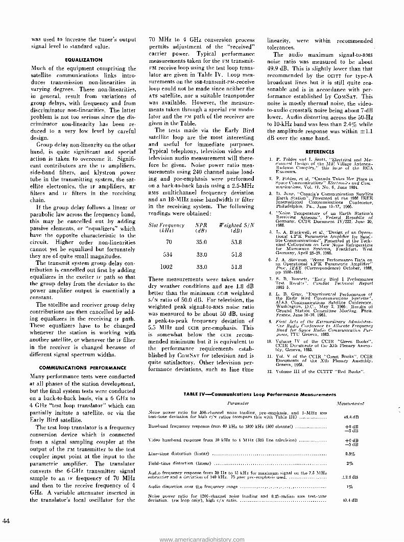
was used to increase the tuner's output signal level to standard value.
EQUALIZATION
Much of the equipment comprising the satellite communications links intro- duces transmission non -linearities in varying degrees. These non -linearities, in general, result from variations of group delays, with frequency and from discriminator non -linearities. The latter problem is not too serious since the dis- criminator non -linearity has been re- duced to a very low level by careful design.
Group delay non -linearity on the other hand, is quite significant and special action is taken to overcome it. Signifi- cant contributors are the IF amplifiers, side -band filters, and klystron power tube in the transmitting system, the sat- ellite electronics, the IF amplifiers, RF
filters and IF filters in the receiving chain.
If the group delay follows a linear or parabolic law across the frequency band, this may be cancelled out by adding passive elements, or "equalizers" which have the opposite characteristic to the circuit. Higher order non -linearities cannot yet be equalized but fortunately they are of quite small magnitudes.
The transmit system group delay con- tribution is cancelled out first by adding equalizers in the exciter IF path so that the group delay from the deviator to the power amplifier output is essentially a constant.
The satellite and receiver group delay contributions are then cancelled by add- ing equalizers in the receiving IF path. These equalizers have to be changed whenever the station is working with another satellite, or whenever the IF filter in the receiver is changed because of different signal spectrum widths.
COMMUNICATIONS PERFORMANCE
Many performance tests were conducted at all phases of the station development, but the final system tests were conducted on a back -to -back basis, via a 6 GHz to 4 GHz "test loop translator" which can partially imitate a satellite, or via the Early Bird satellite.
The test loop translator is a frequency conversion device which is connected from a signal sampling coupler at the output of the FM transmitter to the test coupler input point at the input to the parametric amplifier. The translator converts the 6 -GHz transmitter signal sample to an IF frequency of 70 MHz and then to the receive frequency of 4
GHz. A variable attenuator inserted in the translator's local oscillator for the
70 MHz to 4 GHz conversion process permits adjustment of the "received" carrier power. Typical performance measurements taken for the FM transmit - FM receive loop using the test loop trans- lator are given in Table IV. Loop mea- surements on the ssB- transmit -PM- receive loop could not be made since neither the ATS satellite, nor a suitable transponder was available. However, the measure- ments taken through a special PM modu- lator and the PM path of the receiver are given in the Table.
The tests made via the Early Bird satellite loop are the most interesting and useful for immediate purposes. Typical telephony, television video and television audio measurement will there- fore be given. Noise power ratio mea- surements using 240 channel noise load- ing and pre- emphasis were performed on a back -to -back basis using a 2.5 -MHz RMS multichannel frequency deviation and an 18 -MHz noise bandwidth IF filter in the receiving system. The following readings were obtained:
Slot Frequency (kHz)
NPR (dB)
Weighted SIN (dB)
70 35.0 53.8
534 33.0 51.8
1002 33.0 51.8
These measurements were taken under dry weather conditions and are 1.8 dB better than the minimum CCIR weighted s/N ratio of 50.0 dB. For television, the weighted peak signal -to -RMs noise ratio was measured to be about 50 dB, using a peak -to -peak frequency deviation of 5.5 MHz and CCIR pre -emphasis. This is somewhat below the CCIR recom- mended minimum but it is equivalent to the performance requirements estab- blished by COMSAT for television and is quite satisfactory. Other television per- formance deviations, such as line time
linearity, were within recommended tolerances.
The audio maximum signal -to -RMs noise ratio was measured to be about 49.9 dB. This is slightly lower than that recommended by the CCITT for type -A broadcast lines but it is still quite rea- sonable and is in accordance with per- formance established by COMSAT. This noise is mostly thermal noise, the video - to -audio crosstalk noise being about 7 -dB lower. Audio distortion across the 50 -Hz to 10 -kHz band was less than 2.4% while the amplitude response was within {-1.1 dB over the same band.
REFERENCES
1. P. Foldes and I. Scott, "Electrical and Me- chanical Design of the Mill Village Antenna - Radome Complex," this issue of the RCA ENGINEER.
2. P. Foldes, et al, "Canada Takes Her Place in Space Communications" Electronics and Com- munications, Vol. 12, No. 6, June 1964.
3. D. Jung, "Canada's Communication Satellite Earth Station ", Presented at the 1966 IEEE International Communications Conference, Philadelphia, Pa., June 15 -17, 1966.
4. "Noise Temperature of an Earth Station's Receiving Antenna ", Federal Republic of Germany, CCIR Document IV/222, June 20, 1966.
5. L. A. Blackwell, et al, "Design of an Opera- tional 4.2 °K Parametric Amplifier for Satel- lite Communications ", Presented at the Tech- nical Colloquium on Low Noise Refrigeration for Microwave Systems, Frankfurt, West Germany, April 28 -29, 1966.
6. J. A. Stovman, "Some Performance Data on an Operational 4.2 °K Parametric Amplifier" Proc., IEEE (Correspondence) October, 1966, pp 1500 -1501.
7. S. B. Bennett, "Early Bird I Performance Test Results ", ComSat Technical Report 1965 -5.
8. L. B. Gray, "Experimental Performance of the Early Bird Communications Systems ", AIAA Communications Satellite Conference, Washington, D.C., May 2, 1966; Results of Ground Station Committee Meeting, Paris, France, June 14 -16, 1965.
9. Final Acts of the Extraordinary Administra- tive Radio Conference to Allocate Frequency Band for Space Radio Communication Pur- poses, ITU Geneva, 1963.
10. Volume IV of the CCIR "Green Books ", CCIR Documents of the Xth Plenary Assem- bly, Geneva, 1963.
11. Vol. V of the CCIR "Green Books ", CCIR Documents of the Xth Plenary Assembly, Geneva, 1963.
12. Volume III of the CCITT "Red Books ".
TABLE IV- Communications Loop Performance Measurements
Parameter Measurement
Noise power ratio for 300 -channel noise loading, pre- emphasis, and 1 -MHz ails test -tone deviation for high c/N ratios (compare this with Table III) 48.8 dB
Baseband frequency response from 60 kHz to 1300 kHz (300 channel) +0 dB -3 dB
Video baseband response from 10 kHz to 4 MHz (525 line television) +0 dB -5 dB
Line -time distortion (linear) 0.5%
Field -time distortion (linear) 2%
Audio frequency response from 30 Hz to 15 kHz for maximum signal on the 7.5 MHz subcarrier and a deviation of 140 kHz. 75 gsec pre -emphasis used. ±2.2 dB
Audio distortion over the frequency range 1 %n
Noise power ratio for 1200 -channel noise loading and 0.25- radian ants test -tone deviation. (em loop only), high c/N ratio. 40.4 dB
www.americanradiohistory.com

MULTIPATH EFFECTS IN SPACE COMMUNICATIONS
There are occasions when it is not practical to place highly directive antennas on
space vehicles. Therefore, in a communication link between two terminals using
essentially isotropic antennas, where at least one of the terminals is in the general vicinity of a rough surface (e.g., a planet), scattering from that surface will intro- duce multipath fading which must be taken into account in assessing the perform- ance of the link. The phenomenon of fading (or time variability of the signal)
will of course, occur only if the terminal or the surface changes position with time. This paper discusses the problem of fading under the assumption that the surface
is rigid but the terminal is moving relative to the rough surface. The important systems parameters associated with a given communication link are examined.
The parameters to be considered are the depth and rapidity of fading as well as
the coherence bandwidth of the system.
xE communication link to be ana- 1 lyzed in this paper can be described
as follows: A probe is falling toward the surface of a planet and transmitting to a distant space ship which makes an angle, 92, with respect to the perpendicular to the average surface (Fig. 1). For the moment, the average surface is assumed to be plane; however, the extension to spherical surfaces will be discussed. Both the transmitter and the receiver are connected to essentially "isotropic" an- tennas. Because the position of the probe relative to the rough planetary surface is changing with time, fading at the re- ceiver (in the space ship) will occur. To evaluate the characteristics of this fading, an approach based on the Kirch- hof- Huygens principle was used. The basic theory and limitations of this ap- proach were carefully described by Beck- mann and Spizzichino.' These may be summarized as follows:
1) The rough surface is Gaussian with aiX i> 1, where a is the RMS bump height and X is the radio wavelength.
2) The RMS slope of the surface is fairly small. Mathematically this is written a/T « 1, where T is the correlation length of the surface undulations.
3) The rough surface correlation function is analytic. The mathematical impli- cations of this are discussed by Beck- mann' as well as others.
4) Shadowing of one part of the surface by another as well as multiple scatter- ing are not important considerations. This is a satisfactory approximation so long as (2) above is satisfied.
Final manuscript received June 1, 1967. The re- search reported in this paper was sponsored by National Aeronautics and Space Administration, Ames Research Center, Moffett Field, California, under Contract NAS E -3772.
DR. HAROLD STARAS
Communications Research Laboratory RCA Laboratories, Princeton, New Jersey
AVERAGE SCATTERED POWER
The first quantity to be evaluated is the average scattered power (measured rela- tive to the power in the direct signal). This can be written
Pe =fP °dS (1)
Here, PY represents the average scattered power from the extended surface while P. represents the average scattered power per unit area of surface. From Eq. (10 ) , sec. 12.4.1 of Beckmann and Spizzichino,1 we may write (with minor change of notation) :
P IR 2 r2 cot2
exp ( tan,ß° 47r ri r.` cos \ tan`
(2)
where tan ß° = -2e ( EMs slope of sur-
AVERAGE SURFACE
face undulations)
tan2ß = sirme, sin2e_ - 2 sine, sine_ cosy
( Cos 01+ cos 0 2) 2
and R is the Fresnel reflection coefficient for a plane surface.
Angles, e, and e2, and distances, r, and r2,
in the above formulas are indicated in Fig. 1 with the exception of 99 (identical with e, of Beckmann and Spizzichino') which is the azimuthal angle. The origi- nal contribution in this paper is the eval- uation, in closed form, of the integral in Eq. (1) which had not been accom- plished heretofore. Since it has been assumed that tan ß° (the RMS slope of the rough surface) is a small quantity, the integral in Eq. (1) can be evaluated by the method of "steepest descent."
Fig. 1- Geometry of scattering from rough surface.
PROBE DISTANT SPACE SNIP
45
www.americanradiohistory.com

HAROLD STARAS received his BS degree from CCNY in 1944, his MS from NYU in 1948, and his
PhD in Physics from the U. of Md. in 1955. He joined the National Bureau of Standards in 1948 and served as group leader in radio- propagation re. search and in the performance evaluation of radio systems. He ¡oind RCA in 1954 and was engaged in
tropo- scatter propagation studies and in the systems design of tropo- scatter circuits. He has participa- ted in basic studies of electromagnetic theory in-
cluding "meteor burst" communication, an island as
a natural VLF slot antenna, and dipole characteris- tics in magneto -ionic media. He performed analy- ses of the effect of high-altitude nuclear explosions on communication systems, and conducted radar studies of re -entry veh'cles. Dr. Staras is the author of 18 technical papers. During 1961 -62 he was a
Guggenheim Fellow and visiting professor at the
Technion - Israel Institute of Technology.
o
The integration leads to the remarkably simple yet important conclusion
jRÌ" (3) PD
where Po is the power in the direct wave and R (the Fresnel reflection coefficient) is evaluated at the specular point. The moon and Mars, for example, seem to have reflection coefficients typical of dry sandy soil' with a dielectric constant e ; 3. Using this estimate and neglect- ing ground conductivity, the curves in Fig. 2 are obtained. These curves are essentially independent of frequency.
The horizontally polarized scattered signal is seen to be stronger than the vertically polarized one. For any given polarization. the signal in the neighbor- hood of the receiver is composed of a direct wave and a Rayleigh- distributed scattered wave whose mean power is some number of dB below the direct wave. This number is a function of the direction 9_ and is given in Fig. 2. From results presented by Norton. et al..' Table I was prepared assuming horizontally polarized waves. A similar table for ver- tically polarized and circularly polarized waves could also be prepared but are not given here. The columns in this table represent several typical directions, 8.,,
while the rows define three different reli- ability levels, P, that represent usual
20 o 30° 60°
e2
Fig. 2 -The estimated average scattered power for the lunar or Martian surface.
1l1
90°
design requirement. The numbers in the boxes represent how far down in dB the composite signal (direct plus scattered) is expected to be below the direct signal. This defines a fading range.
TABLE I- Expected Fading Range in dB
Below the Direct Signal
IA 82 0° 30° 45° 60° 79°
99'i 4.7 5.4 7.3 10.6 14.3
99.9'; 7.1 8.5 12.3 19.0 24.1
99.99' , 9.8 11.9 19.0 28.7 34.0
FADING RATES AND FREQUENCY
DIVERSITY
The previous discussion restricted itself to the depth of fading. We now under- take to evaluate the fading rate to be expected. To understand the concept of fading rate as it applies to this situation, it should be recognized that the ground scattered signal can be considered to con- sist of a sum of rays with random relative phase. As the probe changes its position relative to the rough surface, the phases between the various rays change, and fading (i.e. signal fluctuations) occurs. This fading has a typical period or, equivalently, a bandwidth. Actually, the scattered signal will be beating against the direct signal also. But for almost all geometrical situations, the direct signal will lie somewhere near the center of the band of the ground scattered signal so that the beat frequencies between the direct signal and the ground -scattered signal will also lie within the same fad- ing bandwidth. We will, therefore, re- strict ourselves to evaluating the band- widths of the ground- scattered signal.
It is well known in the theory of random functions that the spectrum and the time auto- correlation function are Fourier transforms of each other. There- fore, knowing one implies knowing the other. We will, therefore, discuss the evaluation of the time auto -correlation function C(r) of the random ground scattered signal, E(t). The relation is
C(r) = E(t)E(t +r) (4)
where the bar denotes the average of the quantity under the bar. For the sake of simplicity, we characterize E(t) by a sum of independent phasors (rays) with random relative phase
E(t) = E E, exp (jp,) (5)
From (5), we obtain
E(t)E*(t) = EE,' (6)
www.americanradiohistory.com

f (t)
Fig. 3 -A record from a hypothetical random function of time.
which is the analog of Eq. (1) with E,' representing Po. At (t -F r) we have
E(í-}-7-) = EE,exp [7(q), +Awe)]
where AT, is the systematic (not ran- dom) phase change introduced by the motion of the falling probe. Applying Eq. (4) to (5) and (7) yields
E(t)E *(t +r) _ E E,' exp ( -jAw,)
(8a)
For continuous functions instead of dis- crete variables, Eq. (8a) would be
C(r) =E(r)E*(t+r) = fPo exp [-jk (Ro - R) ] dS (8b)
Where Ro - R is the change in path length (in a time r) of the falling probe from an element of the scattering sur- face. It is assumed that the position of the distant spaceship from the scattering surface does not change in the short period of time, T.
Using the method of "steepest de- scent" mentioned earlier, Eq. (8b) can also be evaluated in closed form. The envelope correlation function R(r) = C(r) ° is shown to be of the form C(0)
where
R(r) = exp (-72/ro") (9)
To - T
8 kvo- sine,
for probe falling with vertical velocity, v. and
T To -
8 kuo cos °,
for probe moving with horizontal veloc- ity, u.
Estimates for a particular probe de- scent toward the Martian surface indi- cates that 62 45 °, T /2o 10, X
1 m and y 3 km /sec. From the above formula, ro ~ 5 X 10' sec which implies a fading rate of 2 kHz (i.e., the band- width of the fading signal is approxi- mately 2 kHz). The above relation be- tween To and the fading rate comes from the basic property of the time auto- corre- lation function: ro is a measure of the typical fading period while its reciprocal is a measure of the bandwidth of the fading.
To give these symbols a physical mean- ing, refer to Fig. 3 which shows a short interval of a record of a random function of time. An estimate of To is indicated in the Figure. The function is sketched as being always positive because it is in- tended to represent a voltage envelope.
Finally, we discuss the question of the coherence bandwidth or frequency diver- sity; i.e., we try to answer the question, "How far apart do two frequencies have to be in order that the fading at these two frequencies be independent ? ". The answer will, of course, be some frequency difference, Af, which is independent of frequency. For frequency diversity, the two frequencies would have to be chosen with a difference greater than Af. On the other hand, to avoid selective fading the intelligence bandwidth on a given carrier must be less than Af. In this paper, Af is evaluated with the aid of the correlation function C (Ak) defined by
C (Ak) = E (k) E* (k Ak)
1 exp [iAk(rl+r,)] Pod S
(10)
Again this integral was evaluated by the method of "steepest descent." The struc- ture of C(Ak), like all correlation func- tions, is such that it is a maximum at Ak = 0 and has dropped to about one - half its maximum value when Ak = Ak0. One can then write the estimate of the coherence bandwidth as
2 c ( Af ., 7L:-1)(L)2 h l40
T (lla)
where Af = 2 Ako and c is the velocity
of light. If it is assumed that 2 10
(which seems to be typical of the moon and Mars), then we may write
Af 2.5/h. (Ilb)
where Af is measured in MHz and ho is the height of the probe in kilometers.
APPLICATION TO A SPHERICAL SURFACE
The previous discussion was restricted to a rough surface which, on the average, was plane. However, the same basic method of "steepest descent" can be used to obtain the analogous result for a rough surface which, on the average, is spheri- cal. The results are more complicated to write down ; however, for altitudes less than 1/40 of the planetary radius and for angles more than 7° above the hori- zon, one can use the formulas quoted earlier in this paper with the understand- ing that the plane surface be drawn tan- gent to the spherical surface at the spec - ular point. The reason this is so is that the method of "steepest descent" indi- cates that the effective scattering region is fairly small and is centered on the specular point if the four assumptions listed at the beginning of the paper are satisfied.
REFERENCES
1. Beckmann, P. and Spizzichino, A., The Scat- tering of Electromagnetic Waves from Rough Surfaces, Pergmnon Press, McMillan Co., N.Y. (1963).
2. Beckmann, P., "Scattering by composite rough surfaces," Proc. IEEE, \al. 53 (1965). p. 1012.
3. Jeffreys, H., and Jeffreys, B. S., Methods of Mathematical Physics, sec. 17.04, p. 503, Cam- bridge University Press (1950).
4. Mulileman, D. O., et al, "A review of radar astronomy, Part II," IEEE Spectrum, vol. 3,
p. 7S (1965).
5. Nortan, K. A., et al, "Probability distribution of the amplitude of a constant vector plus a
Rayleigh distributed vector," Proc. IRE, Oct. 1955.
47
www.americanradiohistory.com
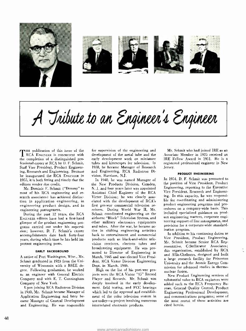
A ''ó,e2o ait egote6614 &ova
THE publication of this issue of the RCA ENGINEER is concurrent with
the completion of a distinguished pro- fessional career at RCA by D. F. Schmit, Staff Vice President, Product Engineer- ing, Research and Engineering. Because he inaugurated the RCA ENGINEER in 1955, it is both fitting and timely that the editors render due credit.
Mr. Dominic F. Schmit ( "Demmy" to most of his RCA engineering and re- search associates) has achieved distinc- tion in application engineering, in engineering product design, and in engineering management.
During the past 12 years, the RCA ENGINEER editors have had a first -hand glimpse of the product engineering pro- grams carried out under his supervi- sion; however, D. F. Schmit's career accomplishments date back forty -four years, during which time he has held im- portant engineering posts.
EARLY BACKGROUND
A native of Port Washington, Wisc., Mr. Schmit graduated in 1923 from the Uni- versity of Wisconsin with a BSEE de- gree. Following graduation, he worked as an engineer with General Electric Company and with E. T. Cunningham Company of New York.
Upon joining RCA Radiotron Division in 1930, Mr. Schmit became Manager of Application Engineering and later be- came Manager of General Development and Engineering. He was responsible
48
for supervision of the engineering and development of the metal tube and the early development work on miniature tubes and kinescopes for television. In 1938, he became Manager of Research and Engineering. RCA Radiotron Di- vision, Harrison, N.J.
In 1940, he was named Manager of the New Products Division, Camden, N. J. and four years later was appointed Assistant Chief Engineer of the RCA Victor Division; he was closely asso- ciated with the development of RCA's first pre -war commercial television re- ceivers. During World War II, Mr. Schmit coordinated engineering on the airborne "Block" Television System, and other military electronics equipments and tubes. After the war, he became ac- tive in shifting engineering activities back to entertainment and commercial products such as black- and -white tele- vision receivers, electron tubes and broadcasting equipment. He was pro- moted to Director of Engineering in March, 1945 and was elected Vice Presi- dent, RCA Victor Division Engineering Dept. in March, 1946.
High on the list of his post -war pro- jects were the RCA Victor "45" Record Player and Records. Mr. Schmit was deeply involved in the early develop- ment, field testing, and FCC hearings which led to the approval and establish- ment of the color television system in use today -a project involving numerous interrelated electronic products.
Mr. Schmit who had joined IRE as an Associate Member in 1925 received an IRE Fellow Award in 1951. He is a registered professional engineer in New Jersey.
PRODUCT ENGINEERING
In 1954, D. F. Schmit was promoted to the position of Vice President, Product Engineering, reporting to the Executive Vice President, Research and Engineer- ing. In this capacity, he was responsi- ble for coordinating and administering product engineering programs and pro- cedures on a company -wide basis. This included specialized guidance on prod- uct engineering matters, corporate engi- neering support of line management, and provision for a corporate -wide standard- ization program.
In addition to his continuing duties as Vice President, Product Engineering, Mr. Schmit became Senior RCA Rep- resentative, C- Stellarator Associates; this organization, established by RCA and Allis- Chalmers, designed and built a large research facility for Princeton University and the Atomic Energy Com- mission for advanced studies in thermo- nuclear fusion.
New Product Engineering services of substantial value to RCA engineers were added such as the RCA Frequency Bu- reau, General Quality Control, Product Engineering Professional Development, and communications programs; some of the most recent of these activities are cited herein.
www.americanradiohistory.com
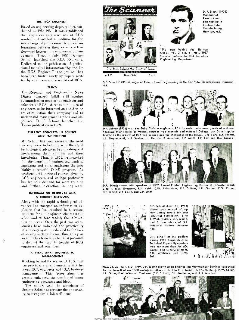
THE 'RCA ENGINEER'
Based on engineering depth studies con- ducted in 1953 -1954, it was established that engineers and scientists at RCA wanted and needed a medium for the interchange of professional technical in- formation between their various activi- ties -and between the engineer and man- agement. Thus, in July, 1955, Demmy Schmit launched the RCA ENGINEER. Dedicated to the publication of profes- sional technical information "by and for the RCA Engineer" -the journal has been perpetuated solely by papers writ- ten by engineers and scientists at RCA.
TREND
The Research and Engineering News Digest (TREND) fulfills still another communication need of the engineer and scientist at RCA. Alert to the desire of engineers to be informed on the diverse activities within their company and to understand management trends and ob- jectives, D. F. Schmit launched the TREND publication in 1959.
CURRENT CONCEPTS IN SCIENCE
AND ENGINEERING
Mr. Schmit has been aware of the need for engineers to keep up with the rapid technological advances by refreshing and modernizing their abilities and their knowledge. Thus, in 1961, he launched for the benefit of engineering leaders, managers and chief engineers the now highly successful CCSE program. As predicted, this series of courses given by RCA engineers and college professors has led to a demand for more training and further instruction for engineers.
INFORMATION RETRIEVAL AND A LIBRARY NETWORK
Along with the rapid technological ad- vances has emerged an information ex- plosion that has resulted in a serious problem for the engineer who wants to select and retrieve rapidly the informa- tion he needs. Over the past two years, studies have indicated the practicality of a library system dedicated to the task of solving such problems; thus, this year an effort has been launched that promises to do just that for the benefit of RCA engineers and scientists.
A VITAL LINK: ENGINEER TO
MANAGEMENT
Working behind the scenes, D. F. Schmit has provided a vital connecting link be- tween RCA engineers and RCA business management. This factor alone has greatly enhanced the destiny of many engineering programs and ideas.
The editors and the associates of Demmy Schmit appreciate the opportun- ity to recognize a job well done.
CO DE IT Al
}e Men Beline :1te E_ec-ron Guns.
Vc LL uo,. 193 No.II
4- "The men behind the Electron Guns "; Vol. 2, No. 11 Nov. 1937 Scanner features the RCA Radiotron Engineering Department.
D. F. Schmit (1935) Manager of Research and Engineering in Electron Tube Manufacturing, Harrison, N.J.
D.F. Schmit (1935) Manager of Research and Engineering in Electron Tube Manufacturing, Harrison, N.J.
D.F. Schmit (19_`6) w.ti five Tube Division engineers, RCA Lancaster, who were guests at a dinner honoring their receipt of Masters degrees from Franklin and Marshall College. Mr. Schmit spoke briefly on the growth of RCA engineering and the challenges of the future. L to R are: D.F. Schmit, L.E. Siepietowski, hi R. Seelen, J.L. Hudson, R. Saunders, C.P. Smith, L.P. Fox and D.J. Ransom.
V D.F. Schmit shown with speakers at 1957 Annual Product Engineering Review at Lancaster plant.
L to R: R.W. Engstrom, F.S. Veith, C.W. Thierfelder, E.E. Spitzer, L.P. Garner, C.G. Carne, D.F. Schmit, D.Y. Smith, and C.P. Smith.
D.F. Schmit (Nov. 18, 1958) shown upon receipt of top New Jersey award for best industrial publication. L to R: W.O. Hadlock, D.F. Schmit, and C. Lauderback of N.J. Industrial Editors Associa- tion.
D.F. Schmit at the podium during 1963 Corporate -wide Technical Papers Symposium held for more than 70 RCA
editors and writers; at right, F.D. Whitmore and C.W. Sall.
Nov. 24, 25 -Dec. 1, 2; 1959: D.F. Schmit shown at an Engineering Management Seminar conducted for the benefit of over 300 managers. Also visible L to R: L. Jacobs, R. Trachtenberg, H.W. Collar, J.R. Gates, F.W. Widman, Chairman (D.F. Schmit), D.L. Nettleton, and J.N. Marshall.
www.americanradiohistory.com
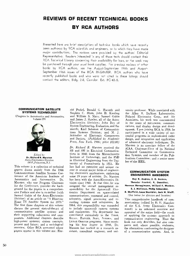
REVIEWS OF RECENT TECHNICAL BOOKS
BY RCA AUTHORS
Presented here are brief descriptions of technical books which have recently been authored by RCA scientists and engineers, or to which they have made major contributions. The reviews were provided by the authors' Editorial Representative. Readers interested in any of these texts should contact their RCA Technical Library concerning their availability for loan, or the book may be purchased through your usual book supplier. For previous reviews of other books by RCA authors, see the August- September 1965 and August - September 1966 issues of the RCA ENGINEER. RCA authors who have recently published books and who were not cited in these listings should contact the editors, Bldg. 2 -8, Camden, Ext. PC -4018.
COMMUNICATION SATELLITE SYSTEMS TECHNOLOGY
(Progress in Astronautics and Aeronautics, Volume 19)
Edited by Dr. Richard B. Marsten
Astro- Electronics Division DEP, Princeton, N.J.
This volume is a collection of technical papers drawn mainly from the 1966 Communications Satellite Systems Con- ference of the American Institute of Aeronautics and Astronautics. Dr. Marsten, who was Program Chairman for the Conference, provides the back- ground for the papers in a comprehen- sive Preface and also is co- author (with Samuel Gubin of the Astro- Electronics Division ) of an article on "A Direct -to- Home TV Satellite System for 1970." The first three chapters of this volume discuss the present state -of- the -art of communication satellite systems and their supporting subsystems and com- ponents. Additional chapters describe high -power systems; system concepts, present and future; and a sociological overview. Other RCA personnel whose papers appear in this volume are: Har-
50
old Perkel, Donald G. Horvath and Stephen C. Blum, John D. Kiesling and William S. Maco, Samuel Gubin and James J. Hawley, all of the Astro- Electronics Division; John Bry of System Engineering, Evaluation, and Re- search; Karl Solomon of Communica- tions Systems Division; and M. J. Schindler of Electronic Components and Devices. (Published by Academic Press, New York, 1966; price $12.00)
Dr. Richard B. Marsten received the SB and SM in Electrical Communica- tions in 1946 from the Massachusetts Institute of Technology, and the PhD in Electrical Engineering from the Uni- versity of Pennsylvania in 1951. He has had an extensive and unique ca- reer in several major fields of engineer- ing electronics applications, embracing some 19 years of activity. Dr. Marsten has been with the Astro- Electronics Di- vision since 1961. At that time, he was assigned the overall management re- sponsibility for the Spacecraft Elec- tronics Department on space -related communications, command and control, telemetry, signal processing and re- cording systems and subsystems. In 1964, this responsibility was expanded to include spacecraft camera systems and equipments. His department has contributed extensively to the TIROS, RELAY, RANGER, SERT, NIMBUS, and LUNAR ORBITER programs. Since receiv- ing his first degree in 1946, Dr. Marsten has worked as a research as- sistant, consultant engineer, and uni-
versity professor. While associated with the Allen B. DuMont Laboratories, Polarad Electronics Corp., and Air Associates, his work was concentrated in the areas of microwave, communi- cations, and display design and devel- opment. Upon joining RCA in 1956, he participated in a wide variety of suc- cessful programs in sophisticated radar design, and integration and application of advanced electronic techniques. Dr. Marsten is an associate fellow of the AIAA, Chairman -Elect of its National Technical Committee on Communica- tion Systems, and member of its Pub- lications Committee; and a senior mem- ber of the IEEE.
COMMUNICATION SYSTEM ENGINEERING HANDBOOK
Roy K. Andres, E. D. Becken, Theodor Frankel, R. Guenther,
Norman Hovagimyan, Willard F. Meeker, S. J. Mehlman, Philip Schneider,
B. Sheffield, Leon Stambler, Jack H. Wolff. (See below for division and location)
This comprehensive handbook of corn - munications (edited by D. H. Hamsher of the U.S. Army Electronics Com- mand) is an informed overview and appraisal of the entire field -the result of applying the systems approach to communication engineering. Thus the book not only describes, but also com- pares and, where possible, evaluates, the alternatives confronting the designer of a communication system. And, in
www.americanradiohistory.com

analyzing the requirements in terms of the possibilities, it facilitates not only optimum design but also improvement of existing systems.
Experts in every aspect of commu- nications have contributed their knowl- edge and experience to this volume, covering principles, customary prac- tices, variations, and standards. Wher- ever appropriate, the book provides theoretical material as well as practical data, and includes original concepts and evaluations not published else- where.
The chapters, titles and names of the RCA contributors are as follows: Chap- ter 1: "System Design and Require- ments," Roy K. Andres, Manager of Advanced Planning, RCA Communica- tions, Inc.; Chapter 3: "Speech Char- acteristics and Acoustic Effects," Wil- lard F. Meeker, Engineer, Communica- tions Systems Division; Chapter 7: -
"Switching Engineering of Switched Systems," Theodor Frankel, Engineer- ing Scientist, Norman Hovagimyan, Sr. Project Member, Technical Staff, Philip Schneider, Manager, Digital System En- gineering, and Leon Stambler, Leader, Advanced Switching Techniques, Com- munications Systems Division; Chapter 11: "Wire and Cable Transmission Characteristics," Jack H. Wolff, Engi- neering Leader, Communications Sys- tems Division; Chapter 15: "High - Frequency Communication Circuits," E. D. Becken, Vice President and Chief Engineer, RCA Communications, Inc.; Chapter 16: "Radio Relay Communica- tion," R. Guenther, Manager, Advanced Communications Technology, S. J. Mehlman, Manager, Advanced Trans- mission Techniques, B. Sheffield, Sr. Project Member, Technical Staff, Com- munications Systems Division. (Pub- lished by McGraw -Hill; 972 pages, 548 illustrations; price $28.50).
SPACECRAFT STRUCTURES
Carl C. Osgood Astro- Electronics Div. DEP, Princeton, N.J.
This book presents an engineering ap- proach to the design of spacecraft struc- tures. The techniques of design analysis and of solution synthesis are explored on the basis of the requirements and constraints on a spacecraft structure in
relation to the proposed mission. The discussion is limited to three discrete phases in the life of the spacecraft: launching, enroute, and operational. The author states, "The structural de- sign of aerospace vehicles rests gen- erally on the base provided by classical mechanics and strength of materials, and the discussions and conclusions in this volume . . . represent an imple- mentation of this approach. But there is an additional body of knowledge developed by both theoretical and em- pirical means, and originating chiefly in attempts to account for the anomalies between data and classical theories ... .
The topics discussed have not been, and some may never be, reduced to routine practice, but the forward -look- ing designer should be able to express, at least qualitatively, a relation between them and his work." The six sections of the volume treat, respectively, mis- sion analysis; design approaches and criteria; analytical techniques; struc- tural types, materials, and methods of fabrication; design examples; and fu- ture techniques. (Published by Pren- tice -Hall, Inc., Englewood Cliffs, New Jersey, 1966; price $15.95)
Carl C. Osgood, Member of the Senior technical Staff, RCA Astro- Electronics Division, received BS and MS degrees in Mechanical Engineering from the University of Maine in 1938 and 1943; an MS degree in Metallurgy from the University of Pennsylvania in 1951, and has completed course requirements for the PhD. Mr. Osgood is Chairman of Mechanical Design Reviews for all AED programs and technical advisor in Mechanical and Materials Engineer- ing for Spacecraft Design. He has been responsible for the mechanical design, construction, and testing of two obser- vation satellites, and was Design Man- ager for the TIROS and RELAY Space- craft. Mr. Osgood joined RCA in 1951 and participated in studies of magnetic memory devices, film transports for high -speed cameras, and made analy- ses of nonlinear servo dampers. Pre- viously, he was a mechanical engineer at the Boston Naval Shipyard respon- sible for the investigations of material problems and failures. He taught me- chanical and metallurgical engineering for 11 years at the Universities of Maine, Vermont, and Pennsylvania. Mr. Osgood has published numerous tech- nical papers and is presently preparing another book entitled "Fatigue Design ". He is a member of the New York Academy of Sciences, the American Society of Metals, the Review Board for "Applied Mechanics Review ", and is a licensed Professional Engineer in both Maine and New Jersey.
FER RO ELECTRICITY
E. Fatuzzo and W. J. Merz Laboratories RCA, Ltd.,
Zurich, Switzerland (Due to the authors' location, biographies and photos were not available for this issue.)
This book gives a physical picture of the ferroelectric phenomena. Special emphasis has been given to the most recent developments of ferroelectric research, which have not been treated in detail in previous books. For ex- ample, the switching properties of fer- roelectrics, their microwave and far - infrared properties, the lattice -dynamics theory, and the second -harmonic gen- eration are covered in detail. The book is designed for the research scientist as well as for the graduate student. Some of the topics treated are thermo- dynamic theory of ferroelectrics; lat- tice dynamics theory; other theories of ferroelectrics; static properties of do- mains; dynamic properties of ferroelec- trics; a physical model for the dynamic properties of ferroelectrics; radiation damage; and applications of ferro- electrics. (Published by North -Holland Publishing Company, Amsterdam; Copyright 1967; 234 pages; U.S. Dis- tributors: Intersciencé Publishers, a Division of John Wiley & Sons Inc., New York; price $11.25)
INSTRUMENTATION FOR MICROELECTRONICS
R. Glicksman, L. A. Murray, R. W. Ahrons, T. Gonda, and
M. F. Lamorte (Contributors)
Electronic Components and Devices Somerville, New Jersey
The RCA authors listed above con- tributed Chapter X, "Instrumentation for Advanced Microelectronic Meas- urements." The first section of this chapter describes some advanced meas- uring techniques which employ non- destructive infrared and ultraviolet techniques. These measurements are simple, fast, and accurate, and show promise of extending integrated cir- cuit technology through greater con- trol of material concentration. In the section of opto- electronics, measure- ment techniques of coherent and non - coherent radiation are described. Meas- urements of thermal resistance and time resolved spectra of lasers are also given. The discussion of cryoelectronics includes advanced instrumentation in the area of vacuum systems including the critical area of automatic mask changing. Testing of cryoelectronic circuits including the problems of re- frigeration and instrumentation to de- termine operable limits are also described. (McGraw -Hill Book Co.; price and publication data were not available).
51
www.americanradiohistory.com

52
THE TWO -POUND RADAR Guerrilla warfare partially depends on the ability of the enemy to move undetected in foliage or under the cover of darkness and fog. If deprived of this advantage by a hand -held tactical radar, the guerrilla can be interdicted and dealt with by conventional fire power. Now, for the first time, a rugged, lightweight radar is available for use by the combat infantryman to detect moving targets and dirgct small -arms fire in all weather and visibility condi- tions. This hand -held tactical radar, which can be directly mounted on the M -79 grenade launcher, the M -I6 semi -automatic weapon, or the M -60 auto- matic area -type weapon, combines the ruggedness, reliability, and simplicity of operation which are essential to all- weather operation in the field.
U. A. FRANK, D. L. KRATZER and J. L. SULLIVAN
Mechanical Integration, Practical Weapon System, and Advanced Signal Processing Missile and Surface Radar Division, DEP, Moorestown, N.J.
WORK on the extremely lightweight radars (sometimes euphemistically
referred to as the Two -Pound Radars) began at RCA's Missile and Surface Radar Division, Moorestown, N.J., late in 1965. The entire research and develop- ment program has been RCA sponsored and funded. The result was a family of hand -held radars which are the first all - solid -state radars, the first to successfully employ pseudo- random code and the first light enough to be mounted directly on a hand -held weapon. RCA can now offer
U. A. FRANK received the BSME from the Univer- sity of N. H. in 1947 and did graduate work in
instrumentation at Johns Hopkins University. His initial work was with NACA (now NASA) doing basic research on high temperature sensing and
control. Other positions included assistant to Chief Engineer at Kaiser Metal Products in charge of automation and development programs. Since
joining RCA, M &SR, he was lead mechanical engi- neer on tactical radars such as AN/UPS-1 and
AN /TPS -35. Other assignments included the design, building and installation at the site of Project Marshmallow, the instrumentation of an under- ground nuclear event, as well as principal project engineer on the two -pound radar during the R &D
phase.
J. L. SULLIVAN received the BSEE degree from Rensselaer Polytechnic Institute in January 1951.
As a design engineer, group leader, and manager at RCA, Mr. Sullivan was responsible for the in-
formation processing design on SPS -12 Search
Radar, Bumble Bee, Ter-i;r acking Radar, UPS -I Search Radar, TALOS, EMKWS, TRADEX, and
MADRE. Recently, Mr S Il,.an participated in
the conception, analysis ::..d specifications of sev- eral advanced informatio I processing systems for infrared sensing, multi- function phased array re-
to the military a complete family of these hand -held radars for a variety of tactical applications.
Simplicity of operation is a key to the usefulness of these radars. Furthermore, the use of the pseudo- random code pro- vides a high degree of security, high resistance to countermeasures and per- mits use of the device for secure com- munications. Had all of this been accomplished with complex controls, or requiring extensive training, we would have failed. Experience has shown that
dars, target discrimination radars, multi- static systems and sidelook radar systems. He is e
member of IEEE and received a quarterly Technical Excellence citation in 1966. His work on the hand- held radars was recognized by RCA with the David Sarnoff Outstanding Achievement Award in Engi- neering. He was the team leader of this group.
D. L. KRATZER received the BS from the U.S. Naval Academy in 1947 and the MSEE from Cor- nell University in 1957. Mr. Kratzer held various engineering assignments from 1947 to 1959 in the fleet and shore establishments of the U.S. Navy. During this diverse naval experience, he was Elec- tronics Material Officer of the USS Boston (GAG -1)
and Instructor, Naval Science, Cornell University. Upon completion of his naval service, Mr. Kratzer directed several antenna system R &D projects for military as well as commercial applications at the American Electronics Labs, Colmar, Pa. Since
1960 he has been engaged in radar system analysis and synthesis for M &SR. He presently serves as e
system engineer for tactical handheld radar sys-
tems and medical electronic products for M &SR.
Mr. Kratzer was a member of the team that re-
ceived the David Sarnoff Outstanding Achievement Award in Engineering for the design of the two - pound radar.
U. A. Fronk D. L. Kratzer
4001 Ato
J. L. Sullivan
Fig. 1 -Block diagram of model 2019 radar system.
R,eC
BALANC MOO
CODE AMP
MASTER REAL MULTI
- UECOOER
"P" .s
iMIT ow[R rREc
TTER XTRS
XOIßE -S1G°a
PRODUC
I11IIlllliil RAXOE SELECTDR
SWITCH ANeE CdiRELATIOX
WO* AMP
EA
with only ten minutes of instruction in the theory and the functional controls of the radar, an untrained enlisted man can start using the radar weapon. Further- more, most enlisted personnel become quite enthusiastic about the radar's capa- bilities after about an hour's experience of operating it against a variety of targets.
Presently, there are four models of the two -pound radar. These are listed in Table I. The Model 2019 is a low- power, short -range unit and is described in greatest detail. The Model 2019 radar can detect a man -sized target at ranges up to 500 meters, moving at speeds between a slow walk and 45 mi /h. The target is indicated by an audible tone in a conventional headset, making it un- necessary for the operator to divert his attention from normal visual surveil- lance. Range switching locates the tar- get within one of twenty 25 -meter range segments. Azimuth definition is com- patible with the field of fire of infantry weapons. A communications mode is also provided for secure voice communi- cation between two units at ranges up to 1000 meters. The entire unit is battery operated, requiring only 3 watts of input power.
SYSTEM DESCRIPTION
The hand -held radar is an x -band cw correlation system using a pseudo- random code generated by a shift regis- ter with a feedback loop. Fig. 1 is the block diagram of the system.
The master oscillator supplies all timing signals for the system including that of the code generator and sensitivity time control (sTc) system. The code from the code generator and the STC
Manuscript received April 10, 1967
www.americanradiohistory.com

Fig. 3 -Man walking toward the radar.
signal from the squaring amplifier, are multiplied in the balanced modulator. This signal shifts the phase of an x -hand signal in 180 -degree steps corresponding to the modified code.
The signal from the phase modulator is applied to the circulator (diplexer) and then to the antenna where the phase - coded signal is transmitted to, and re- turns from, the target. The return signal, delayed by the time required to travel the round trip to the target and attenu- ated by special losses, is sent to the mixer. Also applied to the mixer is the undelayed phase -coded signal leaking through the diplexer; this signal serves as local oscillator for the mixer.
The mixer output is the product of the delayed and undelayed codes on the car- rier signals. The carrier signal product is identical to the doppler frequency of the target at low frequencies. The fre- quencies below 12 MHz are passed by the video amplifier to the decoder where this signal and a similar signal derived from the product of delayed and undelayed codes is also applied. The decoder strips the pseudo- random code from the input signal leaving only the STC signal which has been modulated by the doppler sig- nal. This signal is passed through the narrow -band amplifier where the square wave is reduced to its fundamental sine - wave which remains modulated by the doppler signal. The delayed STC signal is mixed with the adjusted STC sinewave of the master oscillator in the phase
Fig. 2 -Parts of the model 2019 radar system.
Fig. 4- Soldier crawling with a rifle at a range of 50 meters.
1 + ft, it1
Fig. 5 -Horse cantering.
detector. The output signal is stripped of the STC signal leaving only the doppler signature of the target. The doppler sig- nal is amplified and sent to earphones.
Range is determined by choosing the proper delay on the shift register such that the output signal is maximum. Nor- mally the signal is only heard in the range element containing the target.
As the target approaches, the signal strength increases inversely as the fourth power of the range. When STC is applied, the signal increases as the inverse square of range with the net result of reducing the domination of nearby targets.
An examination of the signals from simple applied mathematics will be help- ful in understanding the system. The code generated by the shift register, S, = fl(t), where h(t) _ ±1. The STC
signal, S.2 - h(t), where f2(t) _ ±1. The balanced modulator output (S,) is the product of S1 and S. The output of the phase modulator (S4) is
S,= S, coswot
= /,(t) X f2(t) cos coot
where Wo is the radar carrier frequency. The local oscillator (leakage) of the mixer is equivalent to S4, the trans- mitted signal. The reflected and delayed signal is
Ss = f1(t + r) f2 ( t + r) cos wo (t + r)
where r = 2R /C, the round trip delay to the target of range R at C, the speed of light. The output of the mixer (S8) is the product of S, and S;
Sa = f,(t)f2(t)11(t + r)f2(t +T) cos Wot cos w (t + r)
The low- frequency portion of this signal passing through the video amplifier is given
1 { / ( / ( / 1
S'e = fll t /121 t)111 t + r) 21 t + r) cos WoT
The signal applied to the decoder is given by
Sr = f1(t)11(t + T) Mt)
where T is the delay determined by the range switch position on the code generator. The output of the decoder (S) is the product of S'o and Sr
Se= f,2(t)f22(t)f1(t +T)f,(t +T) f -(t + T) COS WoT
f1(t + r)f,(t + T)f2(t +r) cos WoT
since f2(t) = 1, and f,2(t) = 1.
If T = r, that is, if the range delay is properly selected,
58 = f2 (t + T) cos woT
The signal is passed through the narrow - band filter converting the square wave into its fundamental. Hence,
S, = cos w2(t +T) cos cool
where W2 is the fundamental of f2(t). The undelayed STC sinusoidal signal Si, is applied to the phase detector together with S,.
S,,, = cos w,(t + 0)
The phase detector output is S,,. Thus,
Su =S9 ,,
= cos w,(t + r) cos 0)2 (t + ') COS WoT
The low frequency portion of the signal is
s'11 = cos w,(r - 0) cos WT
If 0 is r /2, then
S'1, = sin w2T cos woT
Let WO- be small, then
5,11 - W2T cos woT
= w, R R 2C
cos Wo 2C
At short ranges, this is equivalent to an R' power correction. If
R(t) = Ro + Rot + .
Then,
W2R Wo
S'11 = 2C cos 2C (Ro + Rot + ... + ...)
STC Controlled Target Signature Amplitude
COMPONENT DESCRIPTION
The parts of a delivered 2019 system are shown in Fig. 2. The antenna consists of a stripline dipole phased array. using printed circuit techniques. (Models 3019 and 4019 use a slotted waveguide assem- bly.) The transmitter consists of an RCA 2N3866 transistor feeding into a cavity and comb -line filter. A step -recovery diode picks the 11th harmonic and the signal goes through an isolator into a
four -port circulator. The ports of the circulator are connected to a phase modulator, mixer, and antenna. The
53
www.americanradiohistory.com

Fig. 6 -Two men running -a jeep slows to a stop and then accelerates.
video amplifier, audio amplifier, decoder, and digital circuitry are all solid state and employ integrated circuits to the greatest extent possible.
The standard battery consists of sev- eral nickel- cadmium cells. It is recharge- able from any military vehicle, and will power the system for 12 hours (dusk to dawn) . Other battery variations are single voltages with Dc -to -DC converters, single -use 12 -hour batteries, and a one - hour single -use battery packs weighing about a pound. The earphone has been designed for good low frequency response.
ACCESSORIES
Several accessories expand the range of the basic unit. Available at this time is a manual scanning device, including North orientation and leveling. An auto- matic scanning device fed by a two -ounce battery can be set to scan 90 degrees and 180 degrees. Either or both scanners may be mounted on a lightweight tripod and adjusted in height from 20 to 60 inches. Either or both scanners may also be mounted on a weapon pintle, avail- able on many line vehicles. The Model 4019 has an automatic target alarm. A red light starts blinking when a target is within range. A remote indication is based on the same threshold circuit.
MANIPULATION
The field manipulation of the radar is very simple. A self- locking hinged sleeve slips on the weapon barrel. A tripod for intrusion protection or indirect fire con-
Fig. 7 -Man walking (left) and a woman walking (right).
trol can be set up in less than a minute. After mounting. the operator puts on the earphones and turns the device on; warm -up is not required. The range con- trol is set in the all -range position; thus, any target within range of the radar will be audible. Acquiring the target in the all -range mode establishes azimuth and elevation. Range is ascertained by switching through the various mutually exclusive 25 -meter range bins and re- acquiring the target in one of them. Braille markers around the range-selec- tion knob supplement the visual range indication. Granularity finer than 25 meters is achieved by noting a peaking of volume within the bin as the target moves toward the center of the bin. Range bins of 25 meters were chosen since they correspond to the burst radius of a grenade and to the spray pattern of automatic weapons. In addition. there is a communications receive/send mode.
SIGNATURE ANALYSIS
One of the surprising features of this radar's performance has been the clear and distinct signatures various targets produce. Fig. 3 presents a man walking. The abscissa is time, and the ordinate is frequency (i.e., velocity in a Doppler System ) . Fig. 4 presents a man crawling with a hand weapon. Fig. 5 presents a horse cantering. Fig. 6 is an entire story: starting at left, a jeep enters the range bin and comes to a stop. Men running by the jeep pass it, it starts up and accelerates to catch up with the men.
TABLE 1- Hand -Held Radar Specifications
Model No. 1019 2019 3019 4019
Frequency (MHz) 9250 9250 9250 9250 Detection range (meters) 500 on 0.5ur" 500 on 0.5rn- 1000 on 0.5111' 1500 on 0.5m, Location range (meters) 250 500 1000 3000 Range resolution (meters) Beans pattern (Azimuth x Vert.) Power consumption
(watts /24 vne battery pack)
25 6° x 8° 3
25 6° x 8° 3
25 7° x 6° 4
25 r s 6° 5
Signal output Doppler character Doppler character Doppler character Doppler character .L visual alarm
Height (inches) 9 9 111/4 111/4 Width (incises) 12 12 11% 11% Thickness (inches) 3 3 31/4 41/4 Approximate Weight
(lbs. less battery and accessory items)
2.2 2.2 2.5 3.0
Notes :
Communication mode available as an option. Tripods and scanner heads are available for use with these radars. Mounting considerations available for M -79, M -60, M -14, M -16 weapons. All models have pseudo- random code rsx modulation. Maximum target speed is 45 mi/h ; minimum is 0.75 ft /sec for Models 3019 and 4019, and 2 ft /sec f r
Models 1019 and 2019.
54
The extreme right hand portion clearly shows the signatures of both men and jeep. Lines D and E define the wheel motion, proportional to, but faster than, the main body of the vehicle.
While the development of the two - pound radar was reported widely in the American press, it was surprising to receive a news release from the Russian newspaper Novoye Vremya (New Times), dated July 22, 1966. This article de- scribed the radar as a miraculous gadget which permits detection of the enemy while moving through the jungle! It clearly points out, however, that the radar cannot distinguish between a guer- rilla and a woman. This, however, is not time case: the trace in Fig. 7 shows the difference in signature between a vlan (left) and a woman (right) and the trained ear can ascertain fine nuances in tone better than the oscilloscope. Some close analysis and study has gone into this phenomena and the only con- clusions were that there are more moving parts in one case.
FUTURE PLANS
Mounting the radar on various weapons is a continuing cooperative endeavor between Rock Island Arsenal and RCA Fig. 9. An off- weapon -mount is still in the concept stage. However, many other applications are in proposal stages. An adaptation of the radar to vehicle pro- tection is past the systems concept stage. Shipboard signaling, wave height mea- surements, and several other applications are now being explored.
Fig. 8- On- weapon mount for hand -held radar.
www.americanradiohistory.com

AN APPROACH TO RADIATION EFFECTS
IN MOS DEVICES
When an MIS (Metal- Insulator -Semiconductor) device, such as the MOS tran- sistor, is exposed to nuclear or space radiation, the principal effect is not strictly a degradation as is the case in solar cells or bipolar transistors. Instead, the MIS transistor undergoes a change of operating region, which is in the nature of a shift in the bias- dependent characteristics of the device. Other less signifi- cant changes are I) variations in the shape of the characteristic curve and 2)
increased leakage current; both of these are effectively degradations. The
authors discuss the physics of these effects in MIS devices, briefly survey the known radiation data, and recommend methods of reducing the effects of radiation on the devices.
DR. A. G. HOLMES -SIEDLE, Ldr. Radiation Physics
Astro- Electronics Division
Princeton, N.J.
UtiTII. the advent of the metal -insu- lator- semiconductor (Nits) devices,
the insulator films used on the surface of silicon transistors (and such other devices as integrated circuits and di- odes) functioned as inert "passivating" layers, which reduced electrical leakage at the intersection of the surface and the diffused junction. However, in such Nits devices as the metal- oxide -semicon- ductor ( mos) transistor, the insulator film becomes also an important ele- ment of the electrical operation of the device. in that it supports the metal
DR. A. G. HOLMES -SIEDLE received the BA from Trinity College, Dublin (1954) and the PhD from Cambridge University (1958). He conducted post- doctoral research at the Cambridge University Chemical Laboratories from 1958 to 1960, studying the transfer of energy within biological and chemi- cal systems. From 1960 to 1962, with Hawker -Siddeley Aviation, he worked with a team performing studies on communication satellite systems and lunar ve- hicles, acting as a specialist in the effects of the space environments on systems. With RCA since 1962, Dr. Holmes -Siedle has been involved in study- ing both the fundamental and practical problems
Dr. Holmes -Siedle
and
DR. K. H. ZAININGER
Materials Research Laboratory RCA Laboratories
Princeton, N.J.
gate that supplies an electric field to the semiconductor surface and sepa- rates these two elements electrically. During early development, Nips devices were plagued with serious instability and drift problems caused by ion mo- tion on and through this insulator film, especially at elevated temperature and high -electrical -field conditions. Use of clean handling techniques, development of improved annealing procedures, and modification of source -drain fabrication techniques have made possible, to a
great extent, elimination of the insta-
of radiation environments in fields such as: damage to materials; analysis of space radiation and its effect on space systems; radiation testing of satel- lite components (TIROS, NIMBUS, RELAY, COM- SAT, etc.) ; post -launch analysis of satellite perform- ance in orbit; and studies of instrument payloads for satellites. He is project scientist of two NASA research contracts in this field. Dr. Holmes -Siedle is present'iy engaged in experimental and analytical research on nuclear radiation environments, parti- cularly as they affect space systems. He is leader of the Radiation Physics group of the Astro -Elec- tronics Division, and acts for the division as the central contact and consultant in this field. He is
also a fellow of the British Interplanetary Society, a member of the IEEE and is listed in American Men of Science. He is the author of eight research papers, a book and several technical articles.
DR. KARL H. ZAININGER received the BEE degree (magna cum laude) from City College of New York in 1959; the MSE in 1961, the MA in 1962, and the
PhD in Engineering Physics in 1964 from Princeton University. In 1959 he joined the staff of RCA Lab- oratories where he has been engaged in research on semiconductor devices. He is concerned with MIS device physics and technology as well as with
bilities. However, since 1964, it has further been determined that radiation can cause serious drift and degrada- tion in these devices. Although the causes of the drift are distinctly dif- ferent, the reason for them again is in the insulator film. Some alleviation of these conditions can be accomplished by selection and shielding of the de- vices and by designing tolerant cir- cuits, but there is still a strong need to "harden" mos devices intrinsically by modifying the insulator film.
This survey attempts to relate sur-
measurement techniques, but particularly with the physics of radiation damage in MIS systems. He is
the author of several papers in the above fields, and is also coauthor of a text book on field- effect transistors. In 1965 Dr. Zaininger received an RCA
Laboratories Achievement Award for team perform- ance (shared with A. G. Revesz) for experiments and studies leading to a better understanding of the electrical properties and growth mechanisms of silicon- dioxide films on silicon substrates. Dr. Zain- inger is a member of Tau Beta Pi, Eta Kappa Nu,
Sigma Xi, and the Institute of Electrical and Elec-
tronics Engineers.
Dr. Zaininger
55
www.americanradiohistory.com

Iy
AV, 6V MEG. 6
2
-6 -1 r2 C 2 -6 -4
.10 ti 6 .IO
6
56
2
6
w.
I
IO -0
.10
.8
.8 .6 +2,3
O 6 IG
Fig. 2- Effect of threshold shifts on curve trace.
face physics concepts to present -day MIS devices and the problem of ensur- ing their survival in severe radiation environments. Such environments may arise, for example, from nuclear power generators, from nuclear weapon bursts, or from high- energy particles in space. As well as describing the basic physics of the radiation effects observable in mus devices, this survey will encompass the range of radiation -induced changes that may occur in mass -produced de- vices (such as the electronic designer may have to work with) and draw some conclusions on the implications of these effects.
Radiation produces strong changes in MIS devices by introducing a charge into the insulator layer. We use the word "change" rather than "damage" here for a good reason. Radiation ac- tually degrades the performance of solar cells and NPN transistors. In MIS devices, however, the major effect is only a change in the desired operat-
ing region of the device (Fig. 1). For many cases, the device will still be usable if the user can adjust his cir- cuit to "follow" the operating region along the voltage axis and use it under the new electrical conditions. Fig. 2
shows the effect of a shift of the kind shown in Fig. 1 on the well -known form of the operating curve for an MOs
transistor. The shift to the left at first appears catastrophic in its effect, until it is realized that the device is still operating properly, but in a different quadrant of its /D-VD, curve (the de- pletion mode).
True degradation effects in mos de- vices are also sometimes observed when they are subjected to radiation, but, as will be shown later, these effects (unlike the previously described effect) are not universal. A major cause of the degradation effect is the creation of interface states.
MECHANISMS OF RADIATION DAMAGE
An mus structure (or device) is com- posed of a semiconductor substrate covered by an insulator layer (of about 50 to 5000 Angstrom) , which in turn is covered by a metal electrode or gate (see Fig. 1 insets). The oper- ation of the device is strongly depen- dent on the charge relationships at the two interfaces. Early work on such re- lationships was mainly concerned with the semiconductor -vacuum and semi- conductor -gas systems. In the latter, there was normally an oxide film 30 to 50 Angstroms thick (formed by in- cidental oxidation) , which was con- sidered part of the surface region. The physics of such surfaces was reasonably well understood and the localized elec- tronic states associated with the sur- face region were called surface states. A distinction was made between fast
Fig. 1- Change in operating region of MIS due to radiation exposure.
¡AFTER t
i
CIN PUT
BEFORE
N+
Ec (Si 02)
E (Si)
GATE
v xx OXIDE
Ev (Si)
SILICON
Ec (Si 02)
Fig. 3 -Model for the effect of electron bom- bardment of MIS structures.
and slow surface states, i.e., between states which could exchange charge rapidly or slowly, respectively, with the semiconductor space- charge region. The slow states were generally thought to be at the outside of the oxide film, and the fast ones at the boundary be- tween the semiconductor and the oxide layer.
Nils physics is a natural extension of this early semiconductor surface phys- ics to a system of two solid -solid inter- faces, separated by an insulating film that no longer has negligible thickness. Because of the presence of this film and its two space- charge regions, mns
physics is much more complex than semiconductor surface physics. In ad- dition to this basic complexity, confu- sion also arises because the concepts and terminology used are mostly in- herited from the earlier physics. For example, the distinction between fast and slow surface states is not applic- able in an Nits system. Because of the widespread use of the term surface states, the expression has been retained but its use is in an operational manner. In this usage, the term effective surface states lumps together the effect of work function difference and the two other distinct charge configurations that can be defined for the MIS system:
1) Interface States: These are stationary electronic states located at the (Gibb- sian) plane separating the semicon- ductor from the insulator. They are analogous to the fast surface states mentioned previously. The energy levels for these states can be either within or outside the forbidden gap of the semiconductor. (Simplified energy -band illustrations for the MOs system are shown in Figs. 3 and 10.)
2) Oxide Charge: This is a charge that is trapped in the ."bulk" of the insu- lator film and cannot communicate with the semiconductor surface. There are two forms of this charge: mobile and immobile. The immobile species is
www.americanradiohistory.com

10
>_o
10
AFTER
o -IS 10
BEFORE IDEAL
BIAS, V
Fig. 4-C-V curves, showing the effect of elec- tron bomba-dment on an MIS diode that has a distribution of interface states.
mainly due to traps that are part of the intrinsic defect structure of the insula- tor, whereas the mobile charge is mainly due to ions that are capable of migrating through the insulator, es- pecially during conditions of high field and elevated temperature.
A clear separation of the effective sur- face states into individual components (including their polarity) is difficult to achieve on the basis of one measure- ment technique alone. However, the measurement of the capacitance- versus- voltage characteristic at a frequency of one megahertz can yield interesting and meaningful results if proper experi- mental conditions are established and if the experimental results are carefully interpreted.
In the simplest case, the deviation of the actual C -V curve from the ideal curve (calculated for the same struc- ture) can indicate the presence of sur- face states. Parallel translations are normally indicative of oxide charge, while changes in the slope of the char- acteristic indicate interface states. If the actual curve is to the left of the ideal, the charge in surface states is positive, and if it is to the right, the charge is negative. An example of trapped positive charge in an unirradi- ated sample is shown in Fig. 4 in the curve marked "before ".
In this review, we will ignore the mobile oxide charge and focus much of our attention on the fixed oxide charge. As will be seen, however, the interface states can also be very im- portant in mos transistors (and are probably even more important in bi- polar transistors).
In one of the early fundamental in- vestigations of the radiation effects on Mrs devices" oxygen- and steam -grown mos capacitors were irradiated with 1-
MeV electrons. It was concluded that the exposure of mts structures to ioniz-
ing radiation results in two distinctly different, permanent effects:
1) The creation of interface states (elec- tronic states right at the oxide -silicon interface), and
2) The introduction of positive oxide charge (the buildup of a positive space charge within the oxide).
In the first effect, the number and dis- tribution of the interface states pro- duced by a given radiation dose depends upon the state of the interface before bombardment. The higher the density of states before irradiation, the more states will be introduced by radiation, but the lower the density (i.e., the higher the order at the interface), the more difficult it seems to be to intro- duce disorder. Thus, the destruction of order at the interface by ionizing radiation is probably a cooperative process and, as such, is determined by the perfection of the prebombardment interface structure. The usual case is that in which the original sample shows a wide distribution of interface states over the available energy levels in the forbidden gap of silicon. The den- sity of these states can be, but is not always, strongly increased by irradia- tion. A typical effect of irradiation on the C -V curve of an mos device is shown in Fig. 4. In the special case in which a defect is present at the inter- face, giving rise to a single level of interface states, this single level alone may increase preferentially, giving an unusual "stepped" appearance to the C -V characteristic.'
The second general effect mentioned is the one that always occurs. The mag- nitude of the positive oxide charge in- duced depends upon the defect struc- ture of the oxide, specifically on the density of the hole traps. It is also strongly influenced by the magnitude and polarity of the electric field in the oxide during irradiation, but does not depend on the previous irradiation his- tory of the sample.
Actually, both effects take place si- multaneously, but (depending on the initial density of interface states, the total flux, and the value of polarity of bombardment bias) one or the other will dominate for any one particular sample.
The model for the buildup of the positive space charge within the oxide is now quite widely agreed upon. This model, proposed in 1965,' is summa- rized in Fig. 3. The incident radiation ionizes the oxide by interacting with the silicon- oxygen lattice and generat- ing electron -hole pairs in the oxide. The holes interact subsequently with trapping sites within the oxide, while the radiation -generated electrons either
recombine with the holes or (because they can migrate easily, particularly if aided by a field) move out of the oxide. The radiation -generated holes are fairly immobile and many of them are captured into stationary traps. giv- ing rise to the observed positive charge. The polarity of the field applied to the oxide during irradiation determines the spatial 'location of this charge. Some evidence from irradiation experiments on bulk silica indicates that the trapped holes may be localized on a non- bridg- ing oxygen atom (- Si -0 -) attached to the -Si -O -Si- network.'
The nature of the changes in inter- face state density involved in the first effect is more difficult to describe. A simple model involving acceptor -like traps with energy levels within the for- bidden gap of silicon has been pre- sented.' However, the exact structure of the states cannot yet be determined.
Fig. 5- Change in operating recion of p -chan- nel MOS transistors under 1 -MeV electron ra- diation.
0 -14 -12 -10 -8 -6
BIAS , V
-4
Fig. 6- General form of shift in MIS character- istics under radiation with gate bias, during environment, VB as a parameter.
HIGH - ENERGY . V PARTICLE
Slay AA®
®O ®®
SILICON
o EXISTING UN- ONIZED HOLE TRAPS
® TRAPPED HOLE
00t= RADIATION-INDUCED INCREASE IN TRAPPED HOLES , -FREE ELECTRON -HOLE PAIRS
Ne 64V
-2
¡Vg25V
AN íY V
2V ANO -
VBO
e IQs ' 10
I MeV ELECTRON FLUENCE (e /cme I
IO í
IOe i s í 5 107
EQUIVALENT ABSOREED DOSE ( RADS )
57
IS
www.americanradiohistory.com
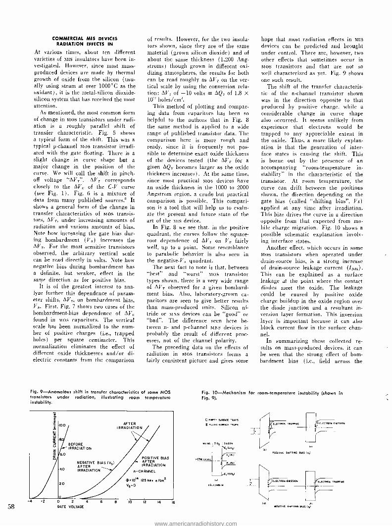
58
COMMERCIAL MIS DEVICES RADIATION EFFECTS IN
At various times, about ten different varieties of MIS insulators have been in- vestigated. However, since most mass - produced devices are made by thermal growth of oxide from the silicon (usu- ally using steam at over 1000 °C as the oxidant), it is the metal -silicon dioxide - silicon system that has received the most attention.
As mentioned, the most common form of change in mos transistors under radi- ation is a roughly parallel shift of transfer characteristic. Fig. 5 shows a typical form of the shift. This was a typical p- channel mos transistor irradi- ated with the gate floating. There is a slight change in curve shape but a major change in the position of the curve. We will call the shift in pinch - off voltage "AVr ". AVT corresponds closely to the AV, of the C -V curve ( see Fig. 1) . Fig. 6 is a mixture of data from many published sources.' It shows a general form of the change in transfer characteristics of mos transis- tors, AVE, under increasing amounts of radiation and various amounts of bias. Note how increasing the gate bias dur- ing bombardment ( VB) increases the AVT. For the most sensitive transistors observed, the arbitrary vertical scale can be read directly in volts. Note how negative bias during bombardment has a definite, but weaker, effect in the saine direction as for positive bias.
It is of the greatest interest to ana- lyze further this dependence of param- eter shifts, AVr, on bombardment bias, VB. First, Fig. 7 shows two cases of the bombardment -bias dependence of AVc found in mos capacitors. The vertical scale has been normalized to the num- ber of positive charges (i.e., trapped holes) per square centimeter. This normalization eliminates the effect of different oxide thicknesses and /or di- electric constants from the comparison
of results. However, for the two insula- tors shown, since they are of the same material (grown silicon dioxide) and of about the same thickness (1,200 Ang- stroms) though grown in different oxi- dizing atmospheres, the results for both can be read roughly as AVT on the ver- tical scale by using the conversion rela- tion: AVT of -10 volts = AQr of 1.8 X 10' holes /cm'.
This method of plotting and compar- ing data from capacitors has been so helpful to the authors that in Fig. 8 the same method is applied to a wide range of published transistor data. The comparison here is more rough and ready, since it is frequently not pos- sible to determine exact oxide thickness of the devices tested (the AVT for a given AQT becomes larger as the oxide thickness increases). At the same time, since most practical mos devices have an oxide thickness in the 1000 to 2000 Angstrom region, a crude but practical comparison is possible. This compari- son is a tool that will help us to evalu- ate the present and future state of the art of the MIS device.
In Fig. 8 we see that, in the positive quadrant, the curves follow the square - root dependence of AVT on VB fairly well, up to a point. Some resemblance to parabolic behavior is also seen in the negative -VB quadrant.
The next fact to note is that, between "best" and "worst" mos transistor types shown, there is a very wide range of AVT observed for a given bombard- ment bias. Also, laboratory -grown ca- pacitors are seen to give better results than mass -produced units. Silicon ni- tride or MNS devices can be "good" or "bad ". The difference seen here be- tween n- and p- channel MNS devices is probably the result of different proc- esses, not of the channel polarity.
The preceding data on the effects of radiation in mos transistors forms a fairly consistent picture and gives some
Fig. 9- Anomalous shift in transfer characteristics of some MOS transistors under radiation, illustrating room temperature instability.
z ¢ 0
10.0
6.0
4.0
BEFORE IRRADIATION
NEGATIVE BIAS (V,) AFTER IRRADIATION
AFTER IRRADIATION
2.0
0 2
GATE VOLTAGE
POSITIVE BIAS AFTER IRRADIATION
n -CHANNEL
0=101 125 Key e /cm2 VB =O
10 12 14 16
hope that most radiation effects in MIS
devices can be predicted and brought under control. There are, however, two other effects that sometimes occur in mos transistors and that are not so well characterized as yet. Fig. 9 shows one such result.
The shift of the transfer characteris- tic of the n- channel transistor shown was in the direction opposite to that produced by positive charge, while a considerable change in curve shape also occurred. It seems unlikely from experience that electrons would be trapped to any appreciable extent in the oxide. Thus, a more likely explan- ation is that the generation of inter- face states is causing the shift. This is borne out by the presence of an accompanying "room- temperature in- stability" in the characteristic of the transistor. At room temperature, the curve can drift between the positions shown, the direction depending on the gate bias (called "shifting bias ", Vs) applied at any time after irradiation. This bias drives the curve in a direction opposite from that expected from mo- bile charge migration. Fig. 10 shows a possible schematic explanation involv- ing interface states.
Another effect, which occurs in some mos transistors when operated under drain- source bias, is a strong increase of drain -source leakage current (IDES). This can be explained as a surface leakage at the point where the contact diodes meet the oxide. The leakage could be caused by positive oxide charge buildup in the oxide region over the diode junction and a resultant in- version layer formation. This inversion layer is important because it can also block current flow in the surface chan- nel.
In summarizing these collected re- sults on mass -produced devices, it can be seen that the strong effect of born - bardment bias (i.e., field across the
Fig. 10- Mechanism for room -temperature instability (shown in Fig. 9).
E EMPTY SURFACE TRAPS
N FILLED SURFACE TRAPS
METAL MOE ; SILICON
E.a1Q,)
E =(511
E (511
(RIO.)
la
EQUILIBRIUM
LEVEL
IEl
I<1
POSITIVE SHIFTING RIAS IV.)
ELECTRON EMISSION
Id) I.) NEGATIVE SHIFTING BIAS IV.)
ELECTRON TRAPPING
www.americanradiohistory.com
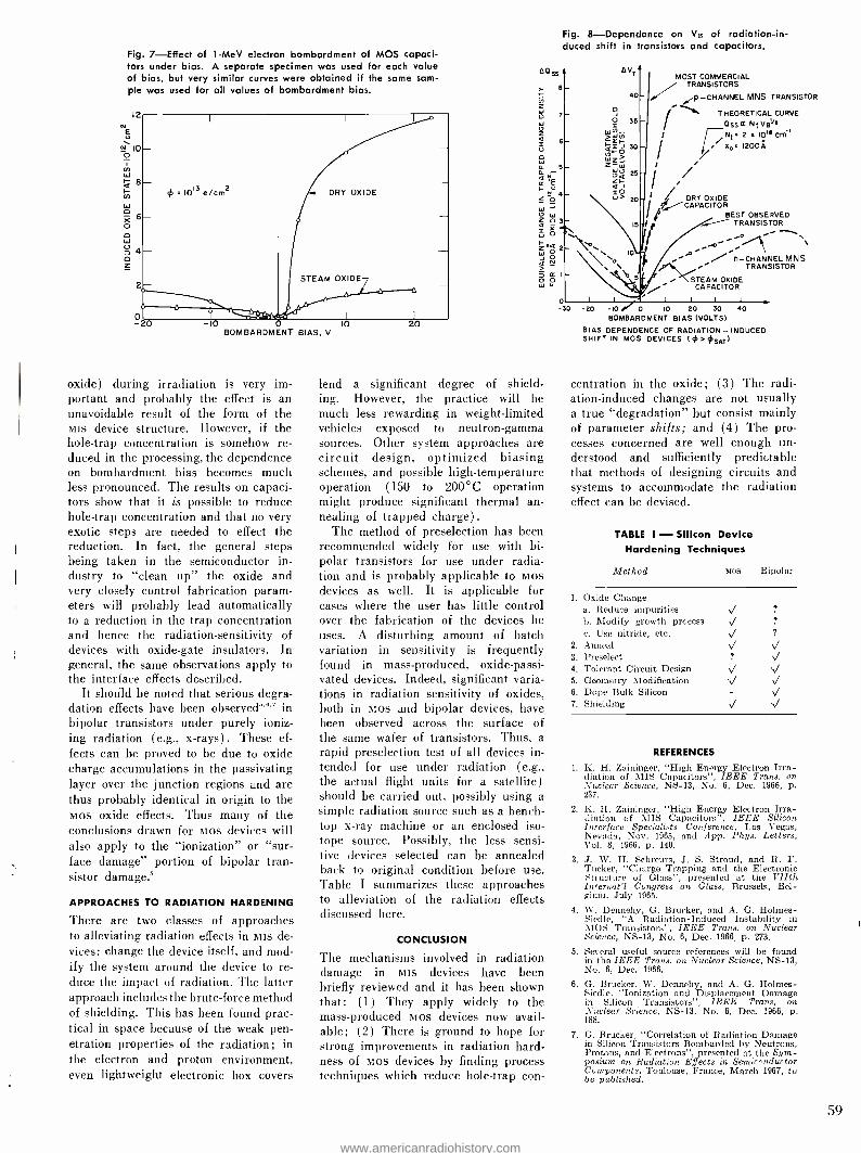
Fig. 7- Effect of 1 -MeV electron bombardment of MOS capaci- tors under bias. A separate specimen was used for each value of bias, but very similar curves were obtained if the same sam- ple was used for all values of bombardment bias.
12
N 10 O
o
0 -20 -10 O 10 BOMBARDMENT BIAS, V
= 1013 e/Cm2 DRY OXIDE
STEAM OXIDE
20
oxide) during irradiation is very im- portant and probably the effect is an unavoidable result of the form of the MIS device structure. However, if the hole -trap concentration is somehow re- duced in the processing, the dependence on bombardment bias becomes much less pronounced. The results on capaci- tors show that it is possible to reduce hole -trap concentration and that no very exotic steps are needed to effect the reduction. In fact, the general steps being taken in the semiconductor in- dustry to "clean up" the oxide and very closely control fabrication param- eters will probably lead automatically to a reduction in the trap concentration and hence the radiation -sensitivity of devices with oxide -gate insulators. In general, the same observations apply to the interface effects described.
It should be noted that serious degra- dation effects have been observed"' in bipolar transistors under purely ioniz- ing radiation (e.g., x- rays). These ef- fects can be proved to be due to oxide charge accumulations in the passivating layer over the junction regions and are thus probably identical in origin to the Mos oxide effects. Thus many of the conclusions drawn for Mos devices will also apply to the "ionization" or "sur- face damage" portion of bipolar tran- sistor damage.'
APPROACHES TO RADIATION HARDENING
There are two classes of approaches to alleviating radiation effects in Nits de- vices: change the device itself, and mod- ify the system around the device to re- duce the impact of radiation. The latter approach includes the brute -force method of shielding. This has been found prac- tical in space because of the weak pen- etration properties of the radiation; in the electron and proton environment, even lightweight electronic box covers
A°95
Fig. 8- Dependence on Vn of radiation-in- duced shift in transistors and capacitors.
A V7 MOST COMMERCIAL
40 / TRANSISTORS // d¡p- CHANNEL MNS TRANSISTOR r ......` THEORETICAL CURVE
O55a NIV412 I Nt 2 a 10'° Crn
/ I Xo 120OÁ
lend a significant degree of shield- ing. However, the practice will be much less rewarding in weight -limited vehicles exposed to neutron -gamma sources. Other system approaches are circuit design, optimized biasing schemes, and possible high- temperature operation (150 to 200 °C operation might produce significant thermal an- nealing of trapped charge).
The method of preselection has been recommended widely for use with bi- polar transistors for use under radia- tion and is probably applicable to Mos devices as well. It is applicable for cases where the user has little control over the fabrication of the devices he uses. A disturbing amount of batch variation in sensitivity is frequently found in mass -produced, oxide- passi- vated devices. Indeed, significant varia- tions in radiation sensitivity of oxides, both in Mos and bipolar devices, have been observed across the surface of the same wafer of transistors. Thus, a rapid preselection test of all devices in- tended for use under radiation (e.g., the actual flight units for a satellite) should be carried out, possibly using a simple radiation source such as a bench - top x -ray machine or an enclosed iso- tope source. Possibly, the less sensi- tive devices selected can be annealed back to original condition before use. Table I summarizes these approaches to alleviation of the radiation effects discussed here.
CONCLUSION
The mechanisms involved in radiation damage in Nits devices have been briefly reviewed and it has been shown that: (1) They apply widely to the mass -produced Mos devices now avail- able; (2) There is ground to hope for strong improvements in radiation hard- ness of Mos devices by finding process techniques which reduce hole -trap con-
II t / DRY OXIDE CAPACITOR
BEST OBSERVED 13 e TRANSISTOR
p n- CHANNEL MNS i TRANSISTOR
STEAM OXIDE CAPACITOR
-30 -20 -10 0 10 20 30 40 BOMBARDMENT BIAS (VOLTS)
BIAS DEPENDENCE OF RADIATION - INDUCED SHIFT IN MOS DEVICES (¢ >OSAT)
centration in the oxide; (3) The radi- ation- induced changes are not usually a true "degradation" but consist mainly of parameter shifts; and (4) The pro- cesses concerned are well enough un- derstood and sufficiently predictable that methods of designing circuits and systems to accommodate the radiation effect can be devised.
TABLE I - Silicon Device Hardening Techniques
Method MIS Bipolar
1. Oxide Change a. Reduce impurities V
b. Modify growth process V c. Use nitride, etc. V
2. Anneal 3. Preselect ? V/
4. Tolerant Circuit Design 5. Geometry Modification 'V s1
6. Dope Bulk Silicon - V 7. Shielding V _V
REFERENCES
1. K. H. Zaininger, "High Energy Electron Irra- diation of MIS Capacitors ", IEEE Trans. on Nuclear Science, NS -13, No. 6, Dec. 1966, p. 237.
2. K. H. Zaininger, "High Energy Electron Irra- diation of MIS Capacitors", IEEE Silicon Interface Specialists Conference, Las Vegas, Nevada, Nov. 1965, and App. Phys. Letters, Vol. 8, 1966, p. 140.
3. J. W. H. Schreurs, J. S. Stroud, and R. F. Tucker, "Charge Trapping and the Electronic Structure of Glass ", presented at the VIIth Internat'l Congress on Glass, Brussels, Bel- gium, July 1965.
4. W. Dennehy, G. Brucker, and A. G. Holmes - Siedle, "A Radiation- Induced Instability in MOS Transistors ", IEEE Trans. on Nuclear Science, NS -13, No. 6, Dec. 1966, p. 273.
5. Several useful source references will be found in the IEEE Trans. on Nuclear Science, NS -13, No. 6, Dec. 1966.
6. G. Brucker, W. Dennehy, and A. G. Holmes - Siedle, "Ionization and Displacement Damage in Silicon Transistors ", IEEE Trans. on Nuclear Science, NS -13, No. 6, Dec. 1966, p. 188.
7. G. Brucker, "Correlation of Radiation Damage in Silicon Transistors Bombarded by Neutrons, Protons, and Electrons ", presented at the Sym- posium on Radiation Effects in Semiconductor Components, Toulouse, France, March 1967, to be published.
59
www.americanradiohistory.com
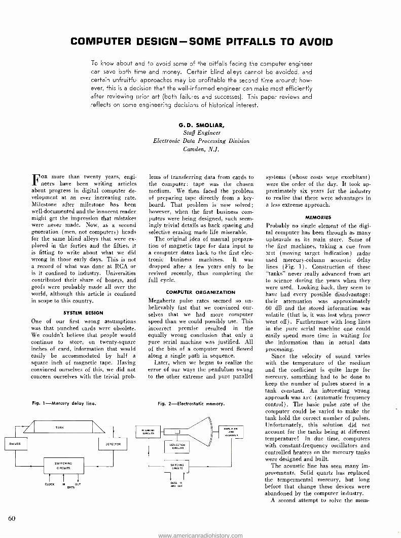
COMPUTER DESIGN - SOME PITFALLS TO AVOID
To know about and to avoid some of the pitfalls facing the computer engineer can save both time and money. Certain blind alleys cannot be avoided, and certain unfruitful approaches may be profitable the second time around; how- ever, this is a decision that the well- informed engineer can make most efficiently after reviewing prior art (both failures and successes). This paper reviews and reflects on some engineering decisions of historical interest.
FOR more than twenty years, engi- neers have been writing articles
about progress in digital computer de- velopment at an ever increasing rate. Milestone after milestone has been well- documented and the innocent reader might get the impression that mistakes were never made. Now, as a second generation (men, not computers) heads for the same blind alleys that were ex- plored in the forties and the fifties, it is fitting to write about what we did wrong in those early days. This is not a record of what was done at RCA or is it confined to industry. Universities contributed their share of boners, and goofs were probably made all over the world, although this article is confined in scope to this country.
SYSTEM DESIGN
One of our first wrong assumptions was that punched cards were obsolete. We couldn't believe that people would continue to store, on twenty- square inches of card, information that would easily be accommodated by half a square inch of magnetic tape. Having convinced ourselves of this, we did not concern ourselves with the trivial prob-
Fig. 1- Mercury delay line.
G. D. SMOLIAR, Staff Engineer
Electronic Data Processing Division
Camden, N.J.
lems of transferring data from cards to the computer: tape was the chosen medium. We then faced the problem of preparing tape directly from a key- board. That problem is now solved; however, when the first business com- puters were being designed, such seem- ingly trivial details as back spacing and selective erasing made life miserable.
The original idea of manual prepara- tion of magnetic tape for data input to a computer dates back to the first elec- tronic business machines. It was dropped after a few years only to be revived recently, thus completing the full cycle.
COMPUTER ORGANIZATION
Megahertz pulse rates seemed so un- believably fast that we convinced our- selves that we had more computer speed than we could possibly use. This incorrect premise resulted in the equally wrong conclusion that only a pure serial machine was justified. All of the bits of a computer word flowed along a single path in sequence.
Later, when we began to realize the error of our ways the pendulum swung to the other extreme and pure parallel
Fig. 2- Electrostatic memory.
CLOCK
60
IN OUT DATA
DATA IN AND OUT
systems (whose costs were exorbitant) were the order of the day. It took ap- proximately six years for the industry to realize that there were advantages in a less extreme approach.
MEMORIES
Probably no single element of the digi- tal computer has been through as many upheavals as its main store. Some of the first machines, taking a cue from MTL (moving target indication) radar used mercury -column acoustic delay lines ( Fig. 1) . Construction of these "tanks" never really advanced from art to science during the years when they were used. Looking back, they seem to have had every possible disadvantage: their attenuation was approximately 60 dB and the stored information was volatile (that is, it was lost when power went off) . Furthermore with long lines in the pure serial machine one could easily spend more time in waiting for the information than in actual data processing.
Since the velocity of sound varies with the temperature of the medium and the coefficient is quite large for mercury, something had to be done to keep the number of pulses stored in a tank constant. An interesting wrong approach was AFC (automatic frequency control). The basic pulse rate of the computer could be varied to make the tank hold the correct number of pulses. Unfortunately, this solution did not account for the tanks being at different temperature! In due time, computers with constant -frequency oscillators and controlled heaters on the mercury tanks were designed and built.
The acoustic line has seen many im- provements. Solid quartz has replaced the tempermental mercury, but long before that change these devices were abandoned by the computer industry.
A second attempt to solve the mem-
www.americanradiohistory.com
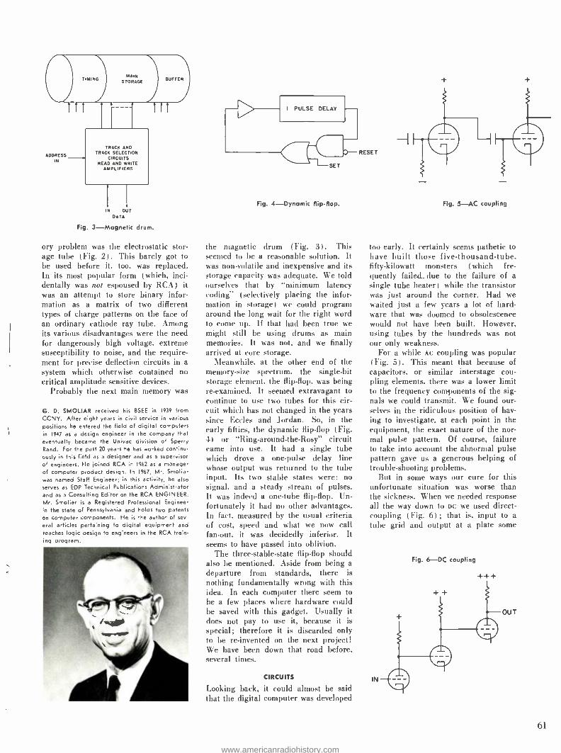
MAIN STORAGE
TRACK AND TRACK SELECTION
CIRCUITS READ AND WRITE
AMPLIFIERS
N OUT DA TA
Fig. 3- Magnetic drum.
ory problem was the electrostatic stor- age tube (Fig. 2) . This barely got to be used before it, too, was replaced. In its most popular form (which, inci- dentally was not espoused by RCA) it was an attempt to store binary infor- mation as a matrix of two different types of charge patterns on the face of an ordinary cathode ray tube. Among its various disadvantages were the need for dangerously high voltage, extreme susceptibility to noise, and the require- ment for precise deflection circuits in a system which otherwise contained no critical amplitude sensitive devices.
Probably the next main memory was
G. D. SMOLIAR received his BSEE in 1939 from CCNY. After eight years in civil service in various positions he entered the field of digital computers in 1947 as a design engineer in the company That
eventually became the Univac division of Sperry Rand. For the past 20 years he has worked continu- ously in this field as a designer and as a supervisor of engineers. He joined RCA in 1962 as a manager of computer product design. In 1967, Mr. Smoliar was named Staff Engineer; in this activity, he also serves as EDP Technical Publications Administrator and as a Consulting Editor on the RCA ENGINEER. Mr. Smoliar is a Registered Professional Engineer in the state of Pennsylvania and holds two patents on computer components. He is the autho of sev-
eral articles pertaining to digital equipment and teaches logic design to engineers in the RCA train- ing o.ogram.
Fig. 4- Dynamic flip-flop.
the magnetic drum (Fig. 3). This seemed to be a reasonable solution. It was non -volatile and inexpensive and its storage capacity was adequate. We told ourselves that by "minimum latency coding" (selectively placing the infor- mation in storage) we could program around the long wait for the right word to come up. If that had been true we might still be using drums as main memories. It was not, and we finally arrived at core storage.
Meanwhile, at the other end of the memory -size spectrum. the single -bit storage element, the flip -flop, was being re- examined. It seemed extravagant to continue to use two tubes for this cir- cuit which has not changed in the years since Eccles and Jordan. So, in the early fifties, the dynamic flip -flop (Fig. 4) or "Ring- around -the -Rosy" circuit came into use. It had a single tube which drove a one -pulse delay line whose output was returned to the tube input. Its two stable states were: no signal, and a steady stream of pulses. It was indeed a one -tube flip -flop. Un- fortunately it had no other advantages. In fact, measured by the usual criteria of cost, speed and what we now call fan -out, it was decidedly inferior. It seems to have passed into oblivion.
The three- stable -state flip -flop should also be mentioned. Aside from being a departure from standards, there is nothing fundamentally wrong with this idea. In each computer there seem to be a few places where hardware could be saved with this gadget. Usually it does not pay to use it, because it is special; therefore it is discarded only to be re- invented on the next project! We have been down that road before, several times.
CIRCUITS
Looking back, it could almost be said that the digital computer was developed
RESET
+
Fig. 5 -AC coupling
too early. It certainly seems pathetic to have built those five- thousand -tube, fifty -kilowatt monsters (which fre- quently failed_due to the failure of a single tube heater) while the transistor was just around the corner. Had we waited just a few years a lot of hard- ware that was doomed to obsolescence would not have been built. However, using tubes by the hundreds was not our only weakness.
For a while AC coupling was popular ( Fig. 5) . This meant that because of capacitors, or similar interstage cou- pling elements, there was a lower limit to the frequency components of the sig- nals we could transmit. We found our- selves in the ridiculous position of hav- ing to investigate. at each point in the equipment, the exact nature of the nor- mal pulse pattern. Of course, failure to take into account the abnormal pulse pattern gave us a generous helping of trouble- shooting problems.
But in some ways our cure for this unfortunate situation was worse than the sickness. When we needed response all the way down to DC we used direct - coupling (Fig. 6) ; that is, input to a tube grid and output at a plate some
IN
Fig. 6 -DC coupling
+ ++
OUT
(tI
www.americanradiohistory.com
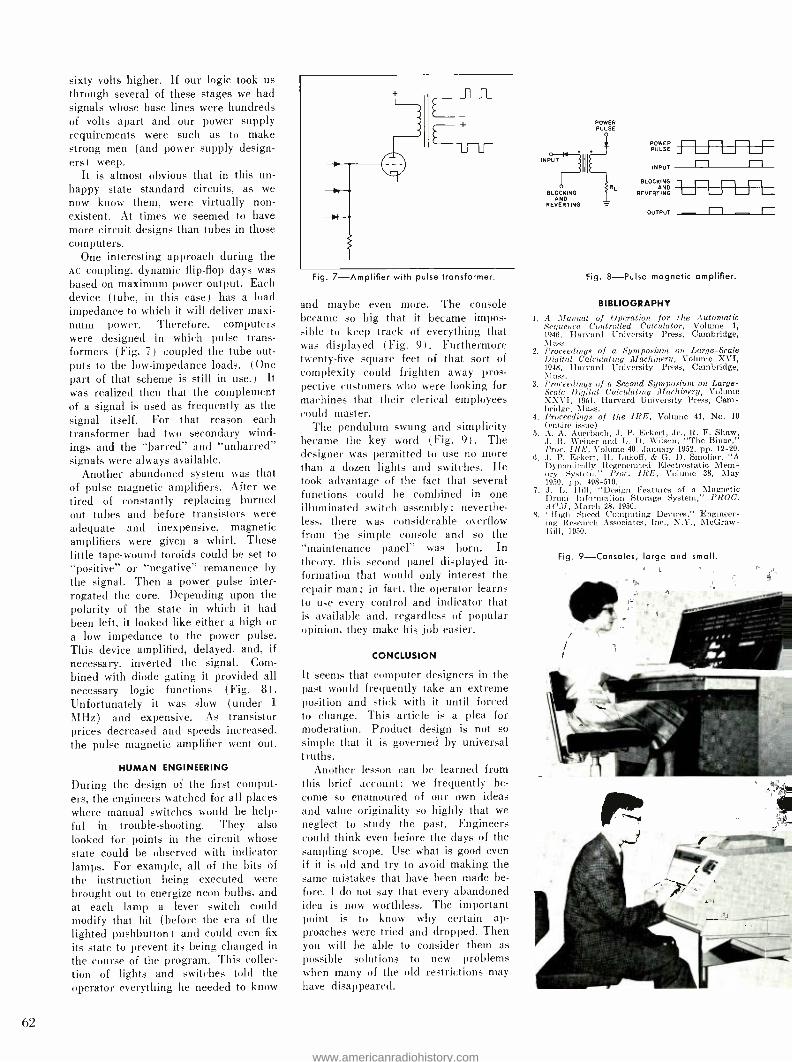
sixty volts higher. If our logic took us through several of these stages we had signals whose base lines were hundreds of volts apart and our power supply requirements were such as to make strong men (and power supply design- ers) weep.
It is almost obvious that in this un- happy state standard circuits, as we now know them, were virtually non- existent. At times we seemed to have more circuit designs than tubes in those computers.
One interesting approach during the AC coupling, dynamic flip -flop days was based on maximum power output. Each device (tube, in this case) has a load impedance to which it will deliver maxi- mum power. Therefore, computers were designed in which pulse trans- formers (Fig. 7) coupled the tube out- puts to the low- impedance loads. (One part of that scheme is still in use.) It was realized then that the complement of a signal is used as frequently as the signal itself. For that reason each transformer had two secondary wind- ings and the "barred" and "unbarred" signals were always available.
Another abandoned system was that of pulse magnetic amplifiers. After we tired of constantly replacing burned out tubes and before transistors were adequate and inexpensive, magnetic amplifiers were given a whirl. These little tape -wound toroids could be set to "positive" or "negative" remanence by the signal. Then a power pulse inter- rogated the core. Depending upon the polarity of the state in which it had been left, it looked like either a high or a low impedance to the power pulse. This device amplified, delayed, and, if necessary, inverted the signal. Com- bined with diode gating it provided all necessary logic functions (Fig. 8). Unfortunately it was slow (under 1
MHz) and expensive. As transistor prices decreased and speeds increased, the pulse magnetic amplifier went out.
HUMAN ENGINEERING
During the design of the first comput- ers, the engineers watched for all places where manual switches would be help- ful in trouble -shooting. They also looked for points in the circuit whose state could be observed with indicator lamps. For example, all of the bits of the instruction being executed were brought out to energize neon bulbs, and at each lamp a lever switch could modify that bit (before the era of the lighted pushbutton) and could even fix
its state to prevent its being changed in the course of the program. This collec- tion of lights and switches told the operator everything he needed to know
62
Fig. 7- Amplifier with pulse transformer.
and maybe even more. The console became so big that it became impos- sible to keep track of everything that was displayed (Fig. 9) . Furthermore twenty -five square feet of that sort of complexity could frighten away pros- pective customers who were looking for machines that their clerical employees could master.
The pendulum swung and simplicity became the key word (Fig. 9). The designer was permitted to use no more than a dozen lights and switches. He took advantage of the fact that several functions could be combined in one illuminated switch assembly; neverthe- less, there was considerable overflow from the simple console and so the "maintenance panel" was born. In theory, this second panel displayed in- formation that would only interest the repair man; in fact, the operator learns to use every control and indicator that is available and, regardless of popular opinion, they make his job easier.
CONCLUSION
It seems that computer designers in the past would frequently take an extreme position and stick with it until forced to change. This article is a plea for moderation. Product design is not so simple that it is governed by universal truths.
Another lesson can be learned from this brief account: we frequently be- come so enamoured of our own ideas and value originality so highly that we neglect to study the past. Engineers could think even before the days of the sampling scope. Use what is good even if it is old and try to avoid making the same mistakes that have been made be- fore. I do not say that every abandoned idea is now worthless. The important point is to know why certain ap- proaches were tried and dropped. Then you will be able to consider them as possible solutions to new problems when many of the old restrictions may have disappeared.
INPUT
BLOCKING AND
REVERTING
POWER PULSE
III
POWER PULSE
INPUT
BLOCKING AND
REVERTING
I-1 I-1
OUTPUT I I . r Fig. 8--Pulse magnetic amplifier.
BIBLIOGRAPHY
1. A Manual of Operation for the Automatic Sequence Controlled Calculator, Volume 1, 1946, Harvard University Press, Cambridge, M ass.
2. Proceedings of a Symposium on Large -Scale Digital Calculating Machinery, Volume XVI, 1948, Harvard University Press, Cambridge, Mass.
3. Proceedings of a Second Symposium on Large - Scale Digital Calculating Machinery, Volume XXVI, 1951, Harvard University Press, Cam- bridge, Mass.
4. Proceedings of the IRE, Volume 41, No. 10 (entire issue)
5. A. A. Auerbach, J. P. Eckert, Jr., R. F. Shaw, J. R. Weiner and L. D. Wilson, The Binar,'' l'roc. IRE, Volume 40, January 1952, pp. 12 -29.
6. .1. P. Eckert, H. Lukoff, & G. D. Smoliar, "A Dynamically Regenerated Electrostatic Mem- ory Systeul," Proc. IRE, Volume 38, May 1950, pp. 498 -510.
7. J. L. Hill, "Design Features of a Magnetic Drum Information Storage System," PROC. ACM, March 28, 1950.
8. "High Speed Computing Devices," Engineer- ing Research Associates, Inc., N.Y., McGraw - Hill, 1950.
Fig. 9- Consoles, large and small.
www.americanradiohistory.com
TV APPLICATIONS OF MOS TRANSISTORS
The latest RCA insulated -gate n- channel silicon field -effect transistors incorpo- rating both single and dual gates have great flexibility for use in a large number of television circuits. Although originally designed for use in RF amplifier stages, these units have the desirable combination of high transconductance and low feedback capacitance which assures excellent performance in many other television stages, including low -level- video, chroma, and AGC circuits. This paper describes several RCA MOS transistors which are being developed especially for television receivers. It also reviews field -effect transistor theory of operation, clarifies the basic designations relating to the various types of field -effect transistors, and discusses several TV- circuit applications in which these devices have been used.
W. M. AUSTIN, D. M. GRISWOLD, J. A. DEAN, and O. P. HART
Consumer Applications and Special Products Development
Electronic Components and Devices, Somerville, N.J.
WHEN the junction -gate field -effect transistor first became commer-
cially available in the early 1960's, it was apparent that these devices with their high input impedance and their wide dynamic range would eventually be used in television receivers. The later devel- opment of the insulated -gate field -effect transistor provided improved gain and frequency performance and further en- couraged those who were working toward the all- solid -state television receiver. Be- cause the majority of insulated -gate field - effect transistors produced to date are of metal - oxide -semiconductor construction, they are more commonly known by the acronym mos.
THEORY OF OPERATION
Field -effect transistors (FET's), whether junction -gate or insulated -gate, are called unipolar devices because current flow depends upon majority carriers alone (as in a resistor) . The amount of current flow is controlled by an electric field. In contrast, current flow within the better known bipolar transistor depends upon the interaction between majority and minority carriers.
The FET uses a semiconductor material such as n -type silicon, which may be visualized as a very small bar. At one Final manuscript rewired Alan", 28, 1967.
end of this bar is an ohmic contact called the source; at the other end is another ohmic contact called the drain. When the FET is "on," charge carriers (elec- trons in n -type silicon) flow through the channel, which effectively joins the source to the drain. This charge -carrier flow is possible because the channel has the same electrical conductivity sign as the source and drain, i.e., if the source and drain are n -type silicon, the channel must also be n -type. The flow of charge carriers in the channel is controlled by elements called gates which are close to the channel.
The interaction of a gate and the chan- nel is comparable to that between the two plates of a capacitor. In this in- stance, a charge placed on one plate (the gate) induces an equal but Opposite charge on the other plate (the channel). Depending upon the polarity of this in- duced charge in the channel, the conduc- tivity of the channel is either decreased or increased from its initial zero -charge state.
If the channel is electrically conduc- tive even in the absence of applied volt- ages, the FET is called a depletion - type. If the channel does not become conductive until a gate -bias voltage is applied, the FET is referred to as an enhancement -type.
GLOSSARY bulk (substrate) gate -a gate formed by the bulk -to- channel ¡unction channel -the conductive path between the source and drain regions of an FET
depletion -mode operation -FET operation with a reverse gate- source voltage to de- crease drain current from the value at Vas -0 depletion -type FET -an FET which has ap- preciable conduction from source to drain at Vos = 0 and which can always be oper- ated in depletion -mode and to varying degrees (depending on construction) in the enhancement mode. drain -the ohmic contact through which charge carriers flow out of an FET
enhancement -mode operation -FET opera- tion with a forward gate- source voltage to increase drain current from the value at Vus =0 enhancement -type FET -an FET which is in
the "off" state at Vos -0 and which there- fore will not operate normally in the deple- tion mode forward bias -that gate -to- source voltage which, when increased, causes an increase in channel conductivity gate -the element or elements of an FET which control the flow of charge carriers between source and drain n- channel -a channel in which the charge carriers are electrons p- channel -a channel in which the charge carriers are holes reverse bias -that gate -to- source voltage which, when increased, causes a decrease in channel conductivity source -the ohmic contact through which charge carriers flow into an FET
63
www.americanradiohistory.com

O. PHILIP HART received the BS degree in Elec-
trical Engineering from the University of Florida in 1955. He joined the RCA training program upon
graduation and was assigned to the Entertainment Tube Application Laboratory. He worked on the
development of circuits for automobile and table AM radios, FM radios, and the sound section of
television receivers. In 1965 he joined the Special
Products Development group and has been work-
ing in the development of circuits using MOS
transistors in television tuners and IF amplifiers. He is a member of the IEEE and Sigma Tau.
JACK A. DEAN received the BS degree in Elec-
tronics Engineering from Indiana Institute of Tech-
nology in 1957. From 1950 to 1954 he served with
the U. S. Air Force as a Staff Sergeant in Radio
Equipment Repair. He joined the RCA trainee
program in 1957, and was assigned to Electron
Tube Test Engineering in Harrison in 1958. He has
been a member of the Tube Applications Labora-
tory since 1960, and the Special Products Develop-
ment Group since 1965. He is a co- inventor on one
patent and a co- author of several published papers. He was awarded the Alpha Gamma Up-
silon Scholarship Award in 1956.
WAYNE M. AUSTIN received the BS degree in
Electrical Engineering from the University of Illinois in 1957 and the MS degree in Electrical Engineer- ing from Rutgers University in 1961. He served as
an electronics and flight officer in the Marine
Corps from 1948 to 1953, before being released to inactive duty with the rank of captain. In 1957 he
joined the RCA graduate study program, and was
assigned to the Entertainment Tube Applications Group in the Receiving Tube Engineering Activity of the Electron Tube Division in Harrison. He has
worked on the development and application of
electron tubes for entertainment applications, on
audio amplifiers, tape recorders, television and FM
radio tube applications, and has written evalua- tions on competitive electron tubes and receiving - tube applications. He is currently working on
transistor applications in color television receivers. He has published eight articles and received one
patent on electron tubes and tube applications. He is a member of Tau Beta Pi, Sigma Tau, and
Sigma Xi.
DAVID M. GRISWOLD, a graduate of Drew Uni- versity, joined RCA as an Engineering trainee at
Harrison, N. J. in July of 1951. From 1952 until 1957
he worked extensively on the design and develop- ment of test circuits for transistors and other semi-
conductor devices. During 1957 he worked as an
Industrial Applications Engineer on high- frequency transistor applications and co- authored a paper on
the drift transistor which was presented at the IRE
International Convention of 1958. He was then
Manager of the Rating Laboratory at the Somer-
ville plant for three years, and Manager of Test
and Reliability Engineering for another year. As a
Senior Engineer in the Consumer Applications De-
partment from 1962 to 1965 he was responsible for evaluation and applications work related to the development of the MOS field -effect transistor. In
1965 he received the Spring Conference Outstand- ing Paper Award of the IEEE Group on Broadcast and Television Receivers. As a member of the Spe-
cial Products Development Department from 1965
to the present, he has continued to work on devel- opment of field -effect transistors. Mr. Griswold is a
member of the IEEE. He has been RCA's represen- tative on the JEDEC JS -8 Committee on Consumer Product Devices since 1959 and chairman since 1963.
He is also a member of the JS -9.1 Committee on Field -Effect transistors.
64
W. M. Austin
J. A. Dean
D. M. Griswold
VUS = 15 V ; In = 5 mA; common source, triode - connected (unless otherwise specified)
Drain Current. ( Von = 0) 16 mA Gate Cutoff Voltage (In = 50 AA) -4 volts Forward Trnnsconductance 7300 µmhos Input Capacitance 6 pF Feedback Capacitance 0 12 pF 200 -MHz Maximum Available Power Gain 20 dB 200 -MHz Maximum Usable Power Gain
(unneutraiized) ** 12.6 dB 200 -MHz Maximum Usable Power Gain
(neutralized) 16 dB 200 -MHz Noise Figure* 4 dB
* Matched and Neutralized. **Circuit loaded for a maximum skew of 20°ío in
the bandpass characteristic.
VDS = 15 V; Voss = +4 V; In = 8 mA ; common source, tetrode -connected (unless otherwise speci- fied)
Drain Current (Voss = 0) 18 mA Gate -No. 1 Cutoff Voltage
(ID = 100 µA) -3.0 volts Gate -No. 2 Cutoff Voltage
(ID = 100 µA; Vain = 0 V) -3.0 volts Forward 'rransconductance
(Gate No. 1 to Drain) 11,000 µmhos Input Capacitance (Gate No. 1 to Source)..5.0 pF Feedback Capacitance
(Drain to Gate No. 1) 0 03 pF max. 200-M II z 7,laximum Available Power Gain..20dB 200 -MHz Maximum Usable Gain
(I'nneutralized)** 20 dB 200 -MHz Noise Figure* 4 dB
*Matched and Neutralized. as Circuit loaded for a maximum skew of 20% in
the bandpass characteristic.
TABLE I- Typical Characteristics of RCA Bey. No. TA2841
TABLE II- Typical Characteristics of RCA Bey. No. TA7149
www.americanradiohistory.com
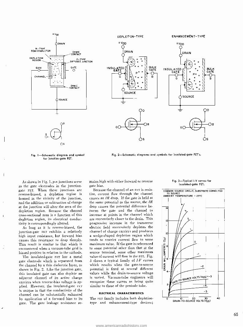
N- TYPE SEMICONDUCTOR
DEPLETION REGION
+VDD
OHMIC CONTACT
P- TYPE DIFFUSED JUNCTION
Fig. 1- Schematic diagram and symbol for junction -gate FET.
As shown in Fig. 1, p -n junctions serve as the gate electrodes in the j unction- gate FET. When these junctions are reverse -biased, a depletion region is formed in the vicinity of the junction, and the addition or subtraction of charge at the junction will alter the area of the depletion region. Because the channel cross -sectional area is a function of this depletion region, its electrical conduc- tivity is correspondingly altered.
As long as it is reverse -biased, the junction -gate FET exhibits a relatively high input resistance, but forward bias causes this resistance to drop sharply. This result is similar to that which is encountered when a vacuum -tube grid is biased positive in relation to the cathode.
The insulated -gate FET has a metal gate electrode which is separated from the channel by a thin dielectric layer, as shown in Fig. 2. Like the junction gate, this insulated gate can also deplete an adjacent channel of its active charge carriers when reverse -bias voltage is ap- plied. However, the insulated -gate FET
is unique in that the conductivity of the channel can be substantially enhanced by application of a forward bias to its gate. The gate leakage resistance re-
DEPLETION -TYPE
+VDD
DRAIN
INSULATED GATE
BULK GATE
ENHANCEMENT -TYPE
+ VDD
DRAIN
INSULATED GATE
Fig. 2- Schematic diagrams and symbols for insulated -gate FET's.
mains high with either forward or reverse gate bias.
Because the channel of an FET is resis- tive, current flow through the channel causes an IR drop. If the gate is held at the same potential as the source, the IR drop causes the potential difference be- tween the gate and the channel to increase at points in the channel which are successively closer to the drain. This progressive increase in the transverse electric field successively depletes the channel of charge carriers and produces a wedge- shaped depletion region which tends to restrict current flow to some maximum value. If the gate is referenced to some potential other than that at the source terminal, some other maximum value of current will flow in the FET. Fig. 3 shows a typical family of I -V curves which results when the gate -to- source potential is fixed at several different valués while the drain -to- source voltage is varied. Vacuum -tube engineers will recognize these curves as being quite similar to those of the pentode tube.
ELECTRICAL CHARACTERISTICS
The FET family includes both depletion - type and enhancement -type devices;
Fig. 3- Typical l -V curves for insulated -gate FET.
COMMON TO
AMBIENT
-SOURCE SOURCE
TEMPERATURE
CIRCUIT, SUBSTRATE
= 25 °C
CONNECTED
14
12
10
ô H
r A W B tr W o.
á J 6 ;1_
4 2- II
-1
70RGE VOLTS
-2
(VGS)' 3
a T
-5
0 10 20 30 DRAIN -TO- SOURCE VOLTS (VDS)
40
www.americanradiohistory.com
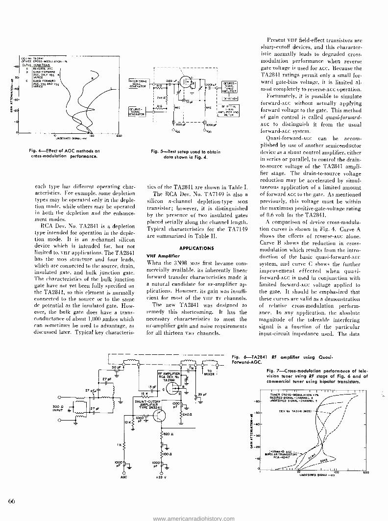
-50
s-,o.
1= -30- <
-20-
i
66
DEV No. TA2841 DEVICE CROSS -MODULATION = I% CURVE CONDITIONS
A REVERSE AGC 8 QUASI- FORWARD
AGC; ONLY VD5 A VARIED
C QUASI-FORWARD AGC. VDS AND VOS VARIED
10 100 UNDESIRED SIGNAL -mV
Fig. 4- Effect of AGC methods on cross -modulation performance.
BOO
INTERFERING- yy
SIGNAL V 1 GENERATOR
DESIRED - SIGNAL
GENERATOR
each type has different operating char- acteristics. For example, some depletion types may be operated only in the deple- tion mode, while others may be operated in both the depletion and the enhance- ment modes.
RCA Dev. No. TA2841 is a depletion type intended for operation in the deple- tion mode. It is an n- channel silicon device which is intended for, but not limited to, VHF applications. The TA2841 lias the mos structure and four leads, which are connected to the source, drain, insulated gate, and bulk junction gate. The characteristics of the bulk junction gate have not yet been fully specified on the TA2841, so this element is normally connected to the source or to the same do potential as the insulated gate. How- ever, the bulk gate does have a trans - conductance of about 1,000 mhos which can sometimes be used to advantage, as discussed later. Typical key characteris-
248D
8Iû
L _
DESIRED - SIGNAL TUNED
AMPLIFIER
I DETECTOR I
SELECTIVE I -KN¿
AMPLIFIER AND METER
Fig. 5 -Test setup used to obtain data shown in Fig. 4.
tics of the TA2841 are shown in Table I. The RCA Dev. No. TA7149 is also a
silicon n- channel depletion -type mos transistor; however, it is distinguished by the presence of two insulated gates placed serially along the channel length. Typical characteristics for the TA7149 are summarized in Table 11.
APPLICATIONS
VHF Amplifier When the 3N98 mos first became com- mercially available, its inherently linear forward transfer characteristics made it a natural candidate for RF- amplifier ap- plications. However, its gain was insuffi- cient for most of the VHF TV channels.
The new TA2841 was designed to remedy this shortcoming. It has the necessary characteristics to meet the RF- amplifier gain and noise requirements for all thirteen VHF channels.
SHUNT -CUTOFF AMPLIFIER
TYPE 2N3241
Present VHF field -effect transistors are sharp -cutoff devices, and this character- istic normally leads to degraded cross - modulation performance when reverse gate voltage is used for AGC. Because the TA2841 ratings permit only a small for- ward gate -bias voltage, it is limited al- most completely to reverse -Ace operation.
Fortunately, it is possible to simulate forward-Ace without actually applying forward voltage to the gate. This method of gain control is called quasi-forward- AGC to distinguish it from the usual forward -Acc system.
Quasi- forward -Acc can be accom- plished by use of another semiconductor device as a shunt control amplifier, either in series or parallel, to control the drain - to- source voltage of the TA2841 ampli- fier stage. The drain -to- source voltage reduction may be accelerated by simul- taneous application of a limited amount of forward AGC to the gate. As mentioned previously, this voltage must be within the maximum positive -gate- voltage rating of 0.6 volt for the TA2841.
A comparison of device cross- modula- tion curves is shown in Fig. 4. Curve A shows the effects of reverse-Ace alone. Curve B shows the reduction in cross - modulation which results from the intro- duction of the basic quasi-forward-Ace system, and curve C shows the further improvement effected when quasi - forward -Acc is used in conjunction with limited forward-Ace voltage applied to the gate. It should be emphasized that these curves are valid as a demonstration of relative cross -modulation perform- ance. In any application. the absolute magnitude of the tolerable interfering signal is a function of the particular input- circuit impedance used. The data
Fig. 6- TA2841 RF amplifier using Quasi - Forward -AGC.
4
Fig. 7- Cross -modulation performance of tele- vision tuner using RF stage of Fig. 6 and of commercial tuner using bipolar transistors.
-50-
a0
-30
ú -20
10
I I I 1 I I I I I I I T il l
TUNER CROSS - MODULATION 1% DESIRED SIGNALeCHANNEL 4 UNDESIRED SIGNALeCHANNEL 5
DEV.No.TA2B41(MOW
/
(FORWARD AGC BIPOLAR TRANSISTO17 A ,
RCA-40417 j GGKS -
......., i /- I X-(n I I PÌ _..---- I I I 1 1 1111
10 100 UNDESIRED SIGNAL-mV
www.americanradiohistory.com

for the curves of Fig. 4 was obtained in the test configuration shown in Fig. 5.
The TA2841 has been tested as an RF
amplifier in a television tuner utilizing a parallel quasi-forward-Ace system. The oscillator (RCA 40237) and mixer (RCA 40236) are typical forward-Ace bipolar transistors. A schematic diagram of the RF stage is shown in Fig. 6. As a positive Ace voltage is applied to this stage, the drain current increases and causes the voltage drop across the bypassed drain resistor to increase. In addition, the 2N3241 shunt cutoff amplifier draws col- lector current through the same drain resistor, and causes a further substantial decrease in drain -to- source voltage with AGC action. The reduction in drain -to- source voltage causes a corresponding reduction in stage gain. The shunt cutoff amplifier also allows the forward gate voltage of the TA2841 to reach, but not exceed, its rated limit of 0.6 volt.
Channel 13 tuner voltage gain to the gate of the first IF stage is approximately 37 dB. Corresponding noise factor is 5 dB, and at least 45 dB of gain reduction can be realized by application of AGC to the RF amplifier stage. In Fig. 7, cross - modulation characteristics of this tuner are compared with those of commercial tuners that use either bipolar transistors or vacuum tubes in the RF- amplifier stage.
The new TA7149 dual -gate mos tran- sistor holds the promise of further im- provement in VHF performance because it has higher transconductance, lower noise figure, and even lower feedback capacitance than the TA2841. In addi- tion, its two serially arranged insulated gates can be biased to custom -tailor its transfer characteristics. If the TA7149 is operated in an RF- amplifier stage in such a way that gate No. 1 is the signal gate and gate No. 2 is at AC ground, it has many of the characteristics of two vacuum triodes arranged in the well - known cascode configuration.'
When gate No. 1 is used for the input signal and gate No. 2 reverse AGC voltage reduces the drain current, the input and output capacitances of the TA7149 re- main relatively constant, as shown in Fig. 8. This effect helps to minimize related bandpass shifting in VHF appli- cations. If special circumstances warrant it, the input- capacitance variations can be reduced even further by application of about 10% of the total reverse AGC
voltage to gate No. 1.
At the higher frequencies, circuit im- pedances are such that the TA7149 is un- conditionally stable when matched and can be operated in an unneutralized cir- cuit for the upper VHF Tv- channels. The
7
6
5
a_
14 U z H
3 a a U
2
O 002
DEV. No. TA7149 VD =I5V; f =50 MHz VGI SET INITIALLY FOR 8mA ID VG2 VARIED FOR ID REDUCTION SHOWN
Ciss
Coss
0.1 1.0 DRAIN CURRENT -mA
Fig. 8- Effect of drain current on input and output ccpacitance of the TA7149.
-60
-50
- 30
á -20
-10
I I 1 1 1 I 1 1 1 I II I I T I I I I I
DEV. No. TA7149 DEVICE CROSS-MODULATION.' % REVERSE AGC TO GATE No.2
1 I 1 1 1 1 1 1 1 I III I I I I
10 100 UNDESIRED SIGNAL -mV
Fig. 9- Cross -modulation performance of the TA7149.
l2
27 pF
r-
pF =3O pF - 15pF
10
600
47 K RF
AMPLIFIER DEV. NO.
TA7149
D
1000 pF 1000 pF 2 120 II
TO- MIXER
1000 pF i 68012
REVERSE AGC
220 K
1000 pF
Fig. 10- Unneutralized TV tuner RF- amplifier stage using the TA7149.
20v
67
www.americanradiohistory.com

IF INPUT
68
1000
REVERSE
100 K IF AMPLIFIER RCA DEV No
TÁ7149 2 --
pF T IOK
330
680 K
5.6 K
4- 20 V
10 K
Fig. 11- Unneutralized TV IF- amplifier stage using the TA7149.
TO NEXT IF STAGE
usual precaution of shielding input from output should be observed.
At the lower VHF tuner frequencies, gain can be maximized by neutralization of the TA7149 amplifier stage. However, if the Channel 2 maximum usable un- neutralized gain is sufficient in a particu- lar tuner application, the circuit design engineer has the option of operating the RF stage unneutralized across the entire tuner frequency spectrum.
TA7149 admittance parameters meas- ured at 44 MHz yield a calculated maxi- mum available gain figure of 35 dB. At this same frequency the calculated maxi- mum usable gain unneutralized is 32 dB. At 200 MHz the calculated maximum available gain figure is 20 dB.
The TA7149 power gain, measured in a test fixture at 200 MHz, substantiates the calculated value. The same test fix- ture and operating conditions provide a typical device noise figure of 3.5 dB. Typical device cross -modulation perform- ance as a function of gain attenuation in a fixture similar to that used for the TA2841 is shown in Fig. 9. The lower input resistance of the TA7149 suggests that its use would result in better tuner cross -modulation than that presently obtained with the TA2841.
An unneutralized TV tuner RF amplifier stage using the TA7149 is shown in Fig. 10. With drain -to- source voltage at 15 volts and a drain current of 8 milli- amperes, Channel 13 tuner voltage gain to the first MOs transistor IF amplifier is 37 dB.
An unneutralized TA7149 TV video IF- amplifier stage is shown in Fig. 11. Measurements on the single stage sub-
FROM CHROMA
AMP
BURST SEPARATOR
BURST AMP.
SSO MHz OSC.
358 MHz AMP
HORIZ. PULSE
VDD
TO K LLER DETECTOR
Fig. 12- Four -stage TA2841 chrominance synchronizing circuit.
stantiated the calculated 44 -MHz device gain figures noted previously.
Color Synchronizing Circuit
The chief function of the chrominance (color) synchronizing circuit is to keep the receiver 3.58 -MHz oscillator precisely in step with the master 3.58 -MHz oscilla- tor at the television transmitting station. The link between transmitter and re- ceiver is provided by an eight -cycle burst of the 3.58 -MHz carrier frequency, which is transmitted during the horizontal - blanking interval immediately following the horizontal -sync pulse.
Fig. 12 shows a four -stage circuit in which Q, the first TA2841 amplifier stage, is biased close to cutoff by the voltage drop across the large 27,000 -ohm source resistor. The time constant of the source resistor and its bypass capacitor is such that the peak of the horizontal keying pulse at the gate turns this stage on just long enough to amplify the burst signal alone.
In Q.0, the second TA2841 common - source amplifier stage, this burst signal is further amplified to the high level required for proper activation of the 3.58 -MHz injection -lock oscillator stage. The crystal, excited by the burst signal, rings synchronously with it and thereby "locks" the local 3.58 -MHz signal into synchronism also.
A TA2841 in the injection -lock oscilla- tor stage, Q. provides several advantages over other types of devices used previ- ously. Because there is no "grid- current" associated with an MOs transistor, the TA2841 oscillator is not disturbed by any of the complications normally caused
FROM RANDPASS AMPLIFIER
FROM 3.56 -MHz
AMPLIFIER
11
TINT CONTROL
Kl KA
DEMODULATOR R
TO DRAIN SUPPLY
CONTROLLED BY COLOR
KILLER
R -Y DEMODULATOR
RCA DEV. No. -(ß- 7A7152 ImH OUT 500 ej
120 220 PF T pF
100 MILLER II 4203 +21 V
'tImH
rp
560
pF B -Y DEMODULATOR RCA DEV. No.
TA7I52 -(B- OUTF.
2.7 0 KA
Fig. 13- Color- demodulator circuit using the TA7152.
Fig. 14- Three -stage TA2841 AGC circuit.
KEYED AGC
FROM AMP VIDEO
DETECTOR
VDD
KEYED AGC
DETECTOR
D
AGC INVERTER
D
+21 V
VDD
G AGC ADJUST
T
WINDING ON HORIZONTAL AOC TO
TRANSFORMER IF
AGC TO
TUNER
www.americanradiohistory.com

CHARGE VOLTAGE
by forward conduction of the control electrode in vacuum tubes, junction -gate field -effect transistors, or bipolar tran- sistors. In addition, the high input im- pedance of the TA2841 permits easier excitation of the 3.58 -MHz crystal in its gate circuit and, in turn, also provides a wider margin of easily controlled oscilla- tor performance than that achieved with the other devices mentioned.
The final TA2841 stage, Q4, serves as a buffer between the 3.58 -MHz oscillator and the tint control, and also provides limiting action to achieve a 3.58 -MHz s =ne -wave signal of constant amplitude for introduction into the R -Y and B -Y color -demodulator stages.
It may be noted that the burst- ampli- fier and the 3.58 -MHz amplifier stages could be eliminated as a cost reduction, but fringe -area performance would suf- fer. In addition, provision of a killer - detector drive signal and a tint control would be somewhat more complicated.
Color Demodulators
RCA Dev. No. TA7152 is a version of the dual -gate MOs field -effect transistor which is characterized specifically for cemodulator applications.
A color demodulator circuit which uses the TA7152 is shown in Fig. 13. The two-insulated gates of the TA7152 pro - vide a color- demodulation circuit which is much simpler than synchronous detection circuits employing bipolar transistors or diodes. For example, the use of diodes and bipolar tria nsistors causes problems in balancing an`áoscilla- tor limiting, as well as loss of gain.
The characteristics of the TA7152 are essentially equivalent to those of a dual - grid converter tube, except for a drain - voltage rating which categorizes the de- vice as a low -level demodulator. For this application, the TA7152 has the neces- sary high transconductance, good inher- ent limiting, and more than adequate
Fig. 15- TA2841 vertical -defection circuit.
DEV. No TA2841
Cl D
+ VDD
BIPOLAR VERTICAL OSCILLATOR
i DRIVE FOR
P -N -P BIPOLAR
OR
DRIVE FOR N -P -N BIPOLAR
output to drive the difference amplifiers with their associated matrix.
Other Color Circuits
The TA2841 has been used successfully for such other low -level circuit functions in color television receivers as the first video amplifier, first chroma amplifier, color -killer detector, color -killer ampli- fier, and chroma bandpass amplifier. In each of these stages, the high input re- sistance, the low input capacitance, and the high transconductance of the TA2841 have proved advantageous.
Automatic Gain Control
Fig. 14 shows an amplifier configuration which uses three TA2841 transistors to amplify, detect, and invert the video signal, and thereby to provide suitable AGC voltages for the RF and IF stages of the television receiver.
The negative video (luminance) signal is directly coupled through an isolation resistance from the video detector to the gate of Q the keyed-Ace driver ampli- fier. A TA2841 is used in this common - source stage because of the low gate - capacitance loading presented to the video detector. In addition, because it is an n- channel depletion -type Mos, its bias characteristics are compatible with a negatively detected video signal.
The video signal is amplified and in- verted in the driver and directly coupled into the gate of Q, the TA2841 which serves as the keyed -Acc detector. The TA2841 is used here for at least two reasons: 1) its high input impedance does not load the keyed-Ace amplifier output; 2) its gate -to- source dynamic range is much greater than the typical emitter -base breakdown range of bipolar transistors. Furthermore, because the gate can swing positive without draw- ing "grid current" as most vacuum -tube systems do, an Mos transistor will not
Fig. 16- TA2841 parabolic waveshaping circuit.
CHARGE VOLTAGE +VDD
RCA DEV NO. Vr TA 2841
D
BIPOLAR VERTICAL OSCILLATOR
.INTERGRATOR CIRCUIT FOR PARABOLIC SHAPING.
SYNC IN
TO SAW TOOTH
OUTPUT
cause the system to "hang up" in the presence of a large input signal. Simi- larly, emitter -base breakdown which can cause hang -up has no equivalent within the operating range of the TA2841. The bilateral nature of an FET does, however, require the insertion of a diode in the drain circuit of the keyed -Acc detector to preven: reverse conduction during the negative peaks of the horizontal flyback pulse.
The negative voltage developed by the keyed -Acc detector is decoupled and applied to the IF strip. This same AGC
voltage is also inverted in another stage, Q3, and then applied to the tuner. A TA2841 is used in this stage because of its minimal loading effect on the AGC
detector.
Vertical Deflection
As shown in Fig. 15, the TA2841 can be used advantageously in vertical- deflec- tion circuits to provide the impedance match needed between the oscillator and the driver or output stage. Because of the high Input impedance of the TA2841, the capacitors associated with the RC time constant in the collector of the ver- tical oscillator can be kept small. In a
circuit which uses bipolar transistors, the capacitors are normally large electroly- tics; with a TA2841, they can be paper types.
Also obtained from the TA2841 are a low- impedance drive of either polarity at the output: an inverted sawtooth at the drain for p -n -p drive, and an in -phase sawtooth at the source for n -p -n drive. Direct coupling into the next stage can be used because the potentiometer, in series with the TA2841 source, is used to adjust the de bias so that scan will commence from cutoff in the output unit.
One interesting added advantage in the use of the TA2841 is that vertical synchronizing signals can be applied to the bulk gate of this unit. Negative sync of approximately 5 volts, when properly integrated, is sufficient for good lock -in with interlace. Also, because the output - transistor transfer characteristic does not match that required by the vertical out- put transformer, parabolic waveshaping must be added to the sawtooth generated by the oscillator. This addition can be accomplished easily in the high- imped- ance gate circuit by the feedback of an integrated sawtooth waveform, as shown in Fig. 16.
BIBLIOGRAPHY
1. D. D. Holmes and T. O. Stanley, "Stability Considerations in Transistor I -F Amplifiers," Transistors I, RCA Laboratories, pp. 403 -421.
2. Color Television Home Study Course, RCA Institutes, Inc., Study Group 3, p. 3.
3. H. Waltman, A. B. Macnee, and C. P. Gadsden, "Low -Noise Amplifier," Proc. IRE, 36 (1948), pp. 700 -708.
69
www.americanradiohistory.com
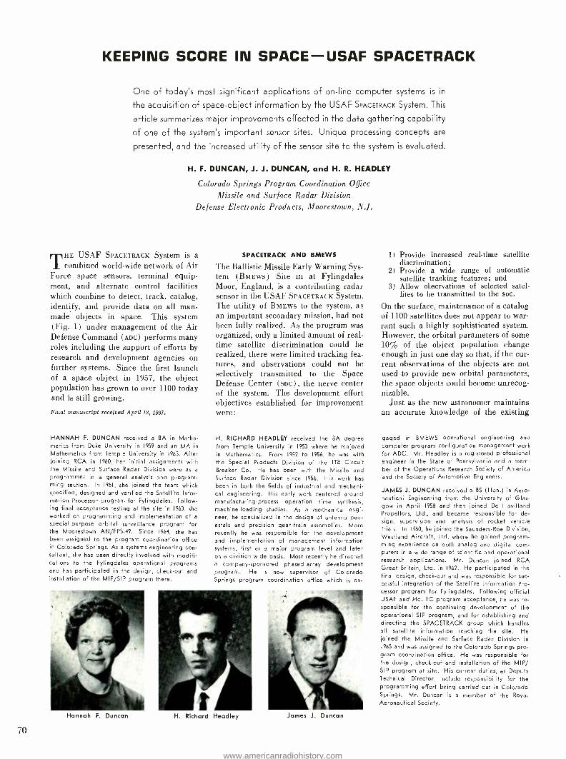
KEEPING SCORE IN SPACE -USAF SPACETRACK
One of today's most significant applications of on -line computer systems is in
the acquisition of space- object information by the USAF SPACETRACK System. This
article summarizes major improvements effected in the data gathering capability
of one of the system's important sensor sites. Unique processing concepts are
presented, and the increased utility of the sensor site to the system is evaluated.
H. F. DUNCAN, J. J. DUNCAN, and H. R. HEADLEY
Colorado Springs Program Coordination Office
Missile and Surface Radar Division
Defense Electronic Products, Moorestown, N.J.
THE USAF SPACETRACK System is a
combined world -wide network of Air Force space sensors, terminal equip- ment, and alternate control facilities which combine to detect, track, catalog, identify, and provide data on all man- made objects in space. This system (Fig. 1) under management of the Air Defense Command (ADc) performs many roles including the support of efforts by research and development agencies on further systems. Since the first launch of a space object in 1957, the object population has grown to over 1100 today and is still growing.
Final manuscript received April 18, 1967.
HANNAH F. DUNCAN received a BA in Mathe- matics from Duke University in 1959 and an MA in
Mathematics from Temple University in 1963. After joining RCA in 1960, her initial assignments with the Missile and Surface Radar Division were as a
programmer in a general analysis and program- ming section. In 1961, she joined the team which specified, designed and verified the Satellite Infor- mation Processor program for Fylingdales. Follow- ing final acceptance testing at the site in 1963, she worked on programming and implementation of a
special -purpose orbital surveillance program for the Moorestown AN /FPS -49. Since 1964, she has been assigned to the program coordination office in Colorado Springs. As a systems engineering con- sultant, she has been directly involved with modifi- cations to the Fylingdales operational programs and has participated in the design, check -out and installation of the MIP /SIP program there.
SPACETRACK AND BMEWS
The Ballistic Missile Early Warning Sys- tem (BmEws) Site ni at Fylingdales Moor, England, is a contributing radar sensor in the USAF SPACETRACK System. The utility of BMEWS to the system, as an important secondary mission, had not been fully realized. As the program was organized, only a limited amount of real - time satellite discrimination could be realized, there were limited tracking fea- tures, and observations could not be selectively transmitted to the Space Defense Center (soc), the nerve center of the system. The development effort objectives established for improvement were:
H. RICHARD HEADLEY received the BA degree from Temple University in 1953 where he majored in Mathematics. From 1952 to 1956, he was with the Special Products Division of the 1TE Circuit Breaker Co. He has been with the Missile and Surface Radar Division since 1956. His work has
been in both the fields of industrial and mechani- cal engineering. His early work centered around manufacturing -process operation time synthesis, machine -loading studies. As a mechanical engi- neer, he specialized in the design of antenna ped- estals and precision gear -train assemblies. More recently he was responsible for the development and implementation of management information systems, first at a major program level and later on a division wide basis. Most recently he directed a company- sponsored phased -array development program. He is now supervisor of Colorado Springs program coordination office which is en-
Hannah F. Duncan
70
H. Richard Headley James J. Duncan
1) Provide increased real -time satellite discrimination;
2) Provide a wide range of automatic satellite tracking features; and
3) Allow observations of selected satel- lites to be transmitted to the SDC.
On the surface, maintenance of a catalog of 1100 satellites does not appear to war- rant such a highly sophisticated system. However, the orbital parameters of some 10% of the object population change enough in just one day so that, if the cur- rent observations of the objects are not used to provide new orbital parameters, the space objects could become unrecog- nizable.
Just as the new astronomer maintains an accurate knowledge of the existing
gaged in BMEWS operational engineering and
computer program configuration management work for ADC. Mr. Headley is a registered professional engineer in the State of Pennsylvania and a mem- ber of the Operations Research Society of America and the Society of Automotive Engineers.
JAMES J. DUNCAN received a BS (Hon.) in Aero- nautical Engineering from the University of Glas- gow in April 1958 and then joined De Havilland Propellors, Ltd., and became respons ble for de- sign, supervision and analysis of rocket vehicle trials. In 1960, he joined the Saunders -Roe Division, Westland Aircraft, Ltd. where he gained program- ming experience on both analog and digital com- puters in a wide range of scientific and operational research applications. Mr. Duncan joined RCA Great Britain, Ltd. in 1962. He participated in the final design, check -out and was responsible for suc- cessful integration of the Satellite Information Pro- cessor program for Fylingdales. Following official USAF and Hq. FC program acceptance, he was re- sponsible for the continuing development of the operational SIP program, and for establishing and directing the SPACETRACK group which handles all satellite information reaching the site. He joined the Missile and Surface Radar Division in
1965 and was assigned to the Colorado Springs pro- gram coordination office. He was responsible for the design, check -out and installation of the MIP/ SIP program at site. His current duties, as Deputy Technical Director, include responsibility for the programming effort being carried out in Colorado Springs. Mr. Duncan is a member of the Royal Aeronautical Society.
www.americanradiohistory.com
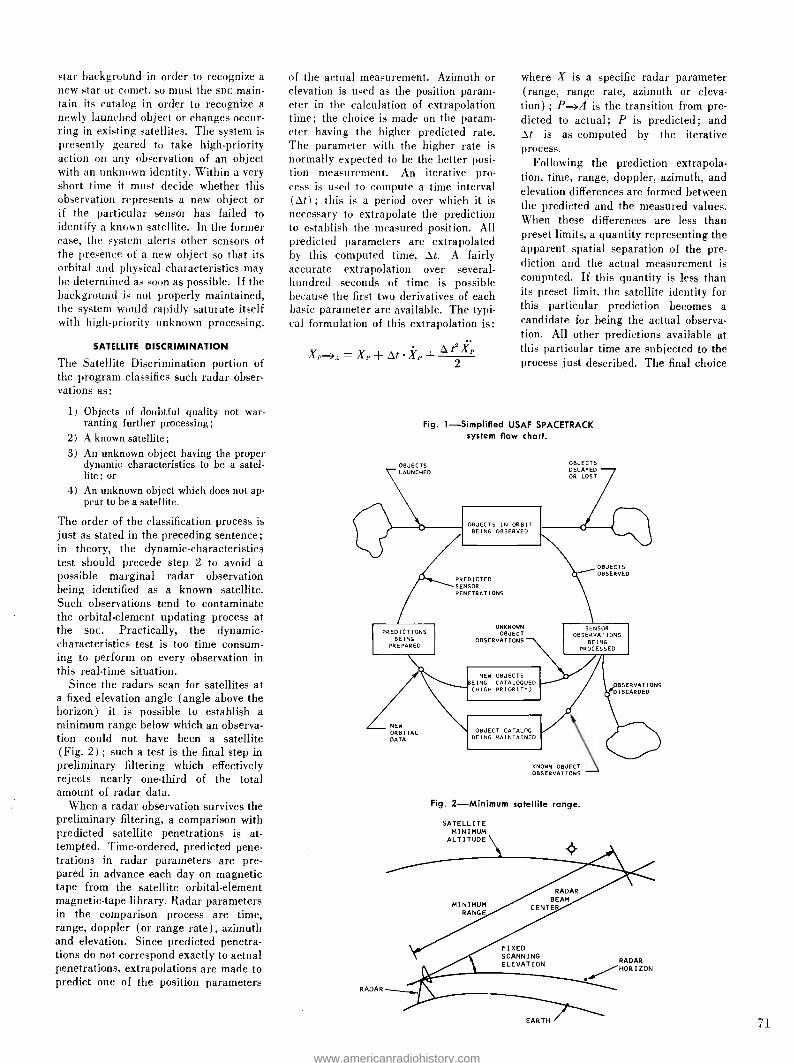
star background in order to recognize a
new star or comet. so must the SIC main- tain its catalog in order to recognize a newly launched object or changes occur- ring in existing satellites. The system is presently geared to take high- priority action on any observation of an object with an unknown identity. Within a very short time it must decide whether this observation represents a new object or if the particular sensor has failed to identify a known satellite. In the former case, the system alerts other sensors of the presence of a new object so that its orbital and physical characteristics may be determined as soon as possible. If the background is not properly maintained, the system would rapidly saturate itself with high -priority unknown processing.
SATELLITE DISCRIMINATION
The Satellite Discrimination portion of the program classifies such radar obser- vations as:
1) Objects of doubtful quality not war- ranting further processing;
2) A known satellite; 3) An unknown object having the proper
dynamic characteristics to be a satel- lite ; or
4) An unknown object which does not ap- pear to be a satellite.
The order of the classification process is just as stated in the preceding sentence; in theory, the dynamic -characteristics test should precede step 2 to avoid a possible marginal radar observation being identified as a known satellite. Such observations tend to contaminate the orbital -element updating process at the SD c. Practically, the dynamic - characteristics test is too time consum- ing to perform on every observation in this real -time situation.
Since the radars scan for satellites at a fixed elevation angle (angle above the horizon) it is possible to establish a minimum range below which an observa- tion could not have been a satellite (Fig. 2) ; such a test is the final step in preliminary filtering which effectively rejects nearly one -third of the total amount of radar data.
When a radar observation survives the preliminary filtering, a comparison with predicted satellite penetrations is at- tempted. Time -ordered, predicted pene- trations in radar parameters are pre- pared in advance each day on magnetic tape from the satellite orbital- element magnetic -tape library. Radar parameters in the comparison process are time, range, doppler (or range rate), azimuth and elevation. Since predicted penetra- tions do not correspond exactly to actual penetrations, extrapolations are made to predict one of the position parameters
of the actual measurement. Azimuth or elevation is used as the position param- eter in the calculation of extrapolation time; the choice is made on the param- eter having the higher predicted rate. The parameter with the higher rate is normally expected to be the better posi- tion measurement. An iterative pro- cess is used to compute a time interval (At) ; this is a period over which it is necessary to extrapolate the prediction to establish the measured position. All predicted parameters are extrapolated by this computed time, At. A fairly accurate extrapolation over several - hundred seconds of time is possible because the first two derivatives of each basic parameter are available. The typi- cal formulation of this extrapolation is:
Xp-A- Xp + At Xp + Ae 2
where X is a specific radar parameter (range, range rate, azimuth or eleva- tion) ; P -+A is the transition from pre- dicted to actual; P is predicted; and At is as computed by the iterative process.
Following the prediction extrapola- tion, time, range, doppler, azimuth, and elevation differences are formed between the predicted and the measured values. When these differences are less than preset limits, a quantity representing the apparent spatial separation of the pre- diction and the actual measurement is computed. If this quantity is less than its preset limit, the satellite identity for this particular prediction becomes a candidate for being the actual observa- tion. All other predictions available at this particular time are subjected to the process just described. The final choice
Fig. 1- Simplified USAF SPACETRACK system flow chart.
OBJECTS LAUNCHED
OBJECTS DECAYED OR LOST
OBJECTS IN ORBIT BEING OBSERVED
OBJECTS OBSERVED
PREDICTED SENSOR PENETRATIONS
PREDICTIONS BEING
PREPARED
UNKNOWN OBJECT
OBSERVATIONS
SENSOR OBSERVATIONS
BEING PROCESSED
NEW OBJECTS :EING CATALOGUED (HIGH PRIORITY) f1BSERVAT DISCARDED
IONS
RADAR
NEW ORBITAL DATA
OBJECT CATALOG BEING MAINTAINED
KNOWN OBJECT OBSERVATIONS
Fig. 2- Minimum satellite range.
SATELLITE MINIMUM
ALTITUDE
MINIMUM RANGE
RADAR BEAM
LENTE
FIXED SCANNING ELEVATION RADAR
/HOR I20N
EARTH 71
www.americanradiohistory.com

of identity, if more than one prediction got through all the steps of the process. is determined by comparing the com- puted spatial separations of the candi- dates; the separation having the smallest magnitude is chosen. If only one candi- date is available, its identity is applied to the actual measurement (Fig. 3) . If no candidates survive the process, the observation is passed on to the final step in the classification process.
The final step in the classification pro- cess starts simply with a refinement of the first quality or preliminary filtering test. The first test examines the range of the object against a minimum range; below this, an observation could not have been a satellite. The refinement in this test concerns the earth model assumed. The former test assumes a spherical earth model while this test contains a
more realistic oblate earth model. Such a test is considerably more complex from a computational standpoint. Preliminary filtering concludes with a data quality test. Basically, it is a test of the standard deviations of the range, azimuth and elevation parameter measurements. If the preliminary filtering tests are passed. the dynamic characteristics tests are performed.
The velocity and energy of the object are then computed from the observed parameters. To be a satellite, this com- puted velocity must lie between mini- mum orbital and escape velocity and the energy must be greater than that of an impacting body. If these criteria are satisfied, the observation is classed as that of an unknown object and is identi- fied as such.
PRE -SET ELEVATION
LIMIT
72
AUTOMATIC SATELLITE TRACKING
The quality of satellite observation data from a radar scanning a fixed elevation angle is a function of the time the space object is in the radar beam. The vertical or elevation dimension of the radar beans is several degrees but the horizontal or azimuth dimension scanned is quite large. An object having a large elevation rate would be expected to yield a relatively poor quality observation, while an object making a low- elevation -rate pass may yield fairly good data. Scan data, even when gathered under the most favorable circumstances, may not be good enough for some purposes. Specifically, better quality data is required for maintaining precise orbits on certain objects (notably payloads) and for readily establishing the orbital parameters of a new or un- known object. This quality of data is
obtainable by tracking the object in ques- tion. What is perhaps even more im- portant is the fact that tracking provides a series of position fixes over the whole period of time the object is within radar limits. When tracking an object, the radar no longer operates at a fixed ele- vation angle but can follow the object over a wide range of parameter variation.
Main considerations in developing the program's automatic satellite tracking capability were to provide considerable flexibility in determining what objects to
track and an object- selection priority scheme; this feature is most necessary because of the possibility of having several objects to track at one time.
Three distinct, non -exclusive options
Fig. 3- Observation identity selection.
PREDICTION FOR ' OBJECT NO. 1
EXTRAPOLATED TO AZIMUTH
OF OBSERVATION
ELEVATION
COMPUTED SPATIAL
SEPARATION
ACTUAL SCAN RADAR OBSERVATION
/ PREVIOUS O-0*----PREDICTION FOR
OBJECT NO. 2
RANGE
PRE -SET AZIMUTH LIMIT
NOTE: DOPPLER AND TIME OMITTED FOR CLARITY
AZIMUTH
PRE -SET RANGE LIMIT
were found for determining what objects to track:
1) Permit specific known satellites to be identified as candidates for tracking at the time the time -ordered penetration predictions are prepared for the day;
2) Request the track of a known satellite by on -line card input of the object number; and
3) Allow automatic tracking of unknown objects.
Most track requests are pre -planned by the SDC and can be entered into the system by option 1. Option 2 allows track requests to be entered at any time during a day's operation. Finally, option 3 permits acquisition of additional in- formation on a suspected new or un- known object.
Automatic tracking is initiated only after a scan radar observation has been passed through the satellite discrimina- tion process and found to be the known satellite for which a track request exists. Assuming that another track is not in progress, the scan radar observation is used to designate a position in space where the tracking radar may expect the object to be at this time. The tracking radar looks at the designated position and begins to track, if an object is there. Track data is consolidated into a single observation every ten seconds. The first of these ten -second, track -data sets is put through the satellite discrimination pro- cess to verify whether the object being tracked is the known or unknown object for which the automatic track was initi- ated. If the wrong object is being tracked, tracking is immediately termi- nated and the track information is dis- carded. If the proper object is being tracked, tracking continues until the ob- ject is no longer visible to the site and track -data sets are formed every ten seconds. These subsequent data sets are assumed to be from the proper object without the use of the discrimination process.
The previous discussion of target tracking assumed that no other track re- quests were in force during the time that the track was in progress. Such is
not always the case; when a number of track requests are present, some arbi- trary set of rules must exist if track information is to be obtained on the maximum number of objects. Such an object selection priority scheme was developed.
Two levels of priority were estab- lished. The higher priority was assigned to track requests resulting from scan - radar observations as opposed to con- tinuing a track in progress. This choice assures that some track data will be ob-
www.americanradiohistory.com

tained on all objects, if time permits. Conflicts arise within each of the priority levels; should two or more track requests be present, the object with the highest probability of being acquired for track- ing is preferred. This acquisition prob- ability is a function of the quality of the scan -radar observation; higher quality data gives a higher acquisition proba- bility than low quality data.
Typical time- shared tracking occur- ring with the object selection priorities just described is shown in Fig. 4. For simplification, a single parameter (azi- muth) versus time representation was chosen in Fig. 4. A scan -radar observa- tion is discriminated as being object No. 1. The termination time for this particular piece of scan data is t1. It is
determined that a track request has been entered for object No. 1 and, since no tracks are in progress, the tracking radar is designated and a track starts. T (1)1
represents the first ten -second track on object No. 1. This data is subjected to
the discrimination process, found to be
object No. 1 and since no other requests are yet present in the system, the track is continued. At the conclusion of the ten -second track, T (2) a higher priority request to track object No. 2 is present so that action is initiated. At the end of that track, T (1) 2, there are no other track requests present and since T(2)1 is the oldest last piece of track data, object No. 1 gets another ten -second track. The track on object No. 2 can- not be resumed after T (4)1 because it has left the site coverage in some param- eter such as elevation, etc.
AZIMUTH
SCAN DATA TERMINATION OBJECT NO. 1
SELECTED SATELLITE DATA TRANSMISSION
A real -time data link exists between the site and the sac. If all observations were to be transmitted from all sites within the USAF SPACETRACK network to the soc, the traffic would amount to nearly one -half million observations per month. This amount of information is neither necessary nor desirable to process at the soc. As with track requests. the soc pre -plans a list of satellites for which it wishes a particular site to transmit data. Normally these satellites are identified as candidates for data transmission at the time the time -ordered penetration predictions are prepared for the day. Transmission of data may also be varied by on -line card input of the object number.
Nine overall options for the transmis- sion of satellite data have been specified by the soc as are shown in Table I. All are presently implemented at the site and can be selected as operational use dictates. Data flow within the site's im- proved satellite information processing program is summarized in Fig. 5. Spe- cific note is made of the sources of the various data shown in Table I.
CONCLUSION
Introduction of the modified program has resulted in marked improvements in four major areas:
1) Availability of satellite information processing was doubled.
2) Satellite discrimination efficiency has been improved.
3) The limited tracking capability was
Fig. 4- Time -shared tracking.
SCAN DATA TERMINATION OBJEC- NO. 2
_Irti
SCAN DATA TERMINATION
II OBJECT NO. 3
O
t2 TIME t3
replaced by a comprehensive satellite tracking facility.
4) The selective transmission feature has permitted more efficient use of the data transmission equipment and ter- minal (suc) facilities.
ACKNOWLEDGMENTS
The writers would like to gratefully ac- knowledge the efforts of Mr. W. J. Mc- Cready, RCA -DEP, who implemented the tracking logic changes necessary to accomplish the automatic satellite track- ing features of the program; and Mr. I.
Morton. RCA -GB Ltd., who developed the mathematical formulation for the dy- namic characteristics test.
TABLE I- SATELLITE
DATA TRANSMISSION OPTIONS
Options Descriptions
1 No Transmission
2 All known satellites
3 Selected known satellites
4 All unknown observations Non-satellites No identification attempted Unknown satellites
5 Unknown satellites
6 All observations Non -satellites Known satellites No identification attempted Unknown satellites
7 All satellites Known satellites
Unknown satellites
8 All unknown observations and selected known satellites
Non -satellites Selected known satellites No identification attempted Unknown satellites
9 Unknown satellites and selected known satellites
Selected known satellites Unknown satellites
Fig. 5 -Site program data flow.
TRACK S
SCAN DATA
COMPARE WITH
PR EDICTEC OBJ CT
PENETRATION
NON- SATEL- LITE
73
www.americanradiohistory.com

TWO- POLARIZATION FM BROADCASTING WITH A SINGLE ANTENNA
To provide better FM service for the automobile radio listener, the FCC permits FM stations to transmit a vertically polarized signal in addition to the standard horizontally polarized signal. Many stations have provided this service by adding a second antenna system for the vertically polarized signal. For applications where a totally new antenna system is desired, RCA has
developed a new transmitting antenna which simultaneously radiates both horizontally and vertically polarized signals from a single set of radiators. In this paper the antenna is described, its characteristics examined, and its application discussed.
Dr. M. S. SIUKOLA, Ldr., Advanced Development Group
Broadcast and Communications Products Division Gibbsboro, N. J.
HE Type BFC circularly polarized FM I broadcast antenna has been devel- oped to provide the dual polarization necessary for improved reception of FM broadcasts by automobile and other FM radios employing vertical whips or other antennas not necessarily best oriented to receive horizontally polarized signals.
Until now, this increasing need has been met by adding a separate vertically polarized transmitting antenna to supple- ment the traditional horizontally polar- ized antenna system. The new FM
transmitting antenna, however, results in only half the weight and wind loading of a combination system for the same service, and reduces installation costs. Moreover, the antenna offers an oppor- tunity to either double the total trans- mitted power or double the antenna aperture, or gain per polarization, with- out exceeding the licensed maximums, and thus provides increased total broad- cast service.
The antenna uses a radiating element made of two dipoles curved into one -turn helices, and mounted in interlaced posi- tion resembling the threads in a double - threaded screw. The dipoles are welded onto a mechanical supporting member, providing a rugged and simple element that radiates circularly polarized signals omnidirectionally. Various gains are ob- tained by stacking these elements ap- proximately at one wavelength spacings.
BENEFITS OF DUAL POLARIZATION The ordinary whip antenna for car and portable radios does a commendable job
Final manuscript received June 16, 1987.
74
of pulling in AM stations. It is funda- mentally a vertically polarized antenna, however, and tends to operate poorly in receiving horizontally polarized waves, such as FM broadcasts. Obviously, if the transmitted field was purely horizontally polarized and the whip antenna, in the case of the auto, was perfectly vertical and centered on the auto roof to pro- vide a symmetrical ground plane, no reception would take place. Thus, it may be said that FM broadcast reception in automobiles using vertical antennas to a great extent results from "discrep- ancies" and is therefore somewhat un- reliable; thus, dual polarization in FM transmission is desirable.
ACHIEVING DUAL POLARIZATION
Dual polarization can be achieved by employing two separate antennas, one for transmitting the horizontally polar- ized signal and another for the vertically polarized signal. Although effective, this method may prove to be complex and ex- pensive; it may also be impractical in some cases where the existing tower structure may be incapable of support- ing the additional weight and wind load. There was the need, therefore, for a single compact antenna to radiate a ver- tically polarized signal in addition to the horizontally polarized signal, both sig- nals for omnidirectional service and at equal power levels.
To meet the requirements for omni- directional service and provide broad- casters with a simple, rugged and economical FM broadcast antenna, RCA developed and is now producing the
BFC series of antennas. Using a single radiator, these antennas radiate the sig- nal in two polarizations in the form of a circularly polarized signal to serve home, portable, and car radios.
SOME ADVANTAGES OF CIRCULAR POLARIZATION
The principal advantage of circularly polarized transmission is that the rotat- ing field provides reception with any logical orientation of a linear receiving antenna. It may not seem important, but in designing a single antenna to radiate half the power horizotally polar- ized and half vertically polarized, a pre- determined fixed phase between the -two radiated signals is desirable. This is an extremely desirable characteristic that is seldom obtained in separate radiating systems.
Of course, if pure vertically and pure horizontally polarized receiving an- tennas are used and propagation does not de- polarize the signals, the phase relationship does not matter; in such cases, the receiving antennas are totally "blind" to the other polarization and thus receive only one. However, receiv- ing antennas such as automobile whips, cord antennas and even built -in antennas vary greatly in polarization and thus re- ceive both signals, so phase may become important.
Performance characteristics of typical dual systems are exemplified in Fig. 1. If polarization is observed in various azimuthal directions, it may be noticed that a range of phase relationships is ob- tained due to space phase variation. If the spacing between the phase centers is a half wavelength or more, any phase difference between the two polarizations will result. In practice, the spacing has
Fig. 1 -Phase relationships between signals radiated by separate horizontally and vertically polarized antennas illustrated in two directions.
HORIZONTALLY POLARIZED RFA ANTENNA
. IN PHASE
HORIZONTAL N VERTICAL FIELDS ORIGINATING IN -PHASE
VERTICAL! POLARIZE!
300V DIPOL ANTENN,
SPACE PHASE
DIFFERENCE
PLAN VIEW
www.americanradiohistory.com

Fig. 3- Current elements (separated by a quar- ter wavelength) rotated and shifted in their respective planes still result in circularly po- larized radiation in one direction.
generally been kept below a quarter wavelength to reduce the overall range of phase variation. However, varying phase differences do exist in present installations.
When the two orthogonally polarized signals with equal power fed into each polarization are examined together, three categories of signal may be obtained ( Fig. 2) . The most common is the case when the two signals have some oblique phase angle between them and the re- sultant field vector thus traces an ellip- tical figure which never touches the origin (Fig. 2a). This is called ellip- tically polarized signal. A characteristic of this signal is that a linear receiving antenna approximately perpendicular to the path of the wave propagation always extracts some energy from the field regardless of the angular orientation of the antenna. The amount, however, var- ies and the ratio of maximum to mini- mum field is expressed by the polariza- tion axis ratio. This is the ratio of major and minor axes of the polarization ellipse. The ratio is not unity even though the same energy is radiated both
Fig. 2 -Total fields produced by two orthogonal signals for elliptical polarization (a), linear polarization (b), and circular polarization (c).
V
0 {>o
< 90 H
¢-o ) H
V
t690 1 H
(a)
( b)
(c)
as
LOCUS OF E
VECTOR
AXIS RATIO 2 TO I (6DB)
AXIS RATIO (mDB)
ÿ .
NEUTRAL PLANE
AXIS RATIO I TO I (0DB)
Fig. 4 -Two current element pairs are arranged to form a single -turn helix. By adding the second current element pair, in the same phase, a circularly polarized signal in all azimuth directions is obtained.
in horizontally and vertically polarized components.
A special case is obtained when the two signals are in phase (Fig. 2b), then the ellipse reduces to a straight line and a 45° linearly polarized signal results. In this case, if the receiving antenna happens to be polarized at the other 45° direction, no signal will be received.
A circularly polarized resultant occurs when the two waves are in phase quadra- ture (Fig. 2c). In this case, a linearly polarized receiving antenna extracts a constant power from the field, whatever the receiving antenna orientation, as long as it is perpendicular to the direc- tion of the wave propagation.
Since 45° polarization theoretically provides a chance of no reception, cir- cular polarization was chosen for the RCA design to provide reception with linear antennas regardless of their orien- tation. Further, circular polarization is more closely related to elliptical polar- ization which exhibits no undesirable characteristics.
OPERATING PRINCIPLES
The evolution of the circularly polarized radiating element may be shown with very simple models. As previously de- scribed, two orthogonal signals, such as vertically and horizontally polarized sig- nals, when in phase quadrature produce a circularly polarized field. These two fields may be produced by two orthog- onal current elements in the same plane. However, phase quadrature may also be produced if two in -phase current ele- ments are separated by a quarter wave- length. This results in a 90° phase difference between the two fields.
If the current elements of this pair are each rotated and shifted in their re- spective planes ( Fig. 3) , circular polar- ization is still maintained in a direction perpendicular to both elements. By adding another current element pair as in Fig. 4, a model of a single turn helix
Fig. 5 -Two resonant half -wave dipoles are curved into one -turn helices and interlaced to maintain constant current for omnidirectional service.
results. A helix with this construction will radiate principally broadside and with circular polarization to all azimuthal directions when the helix periphery, CX = V2Sx and the turn length, Lx _ 0.5, where SX is the spacing between turns. (All parameters are in X.)
As can be seen, this type of helix has a small diameter in terms of wavelength. This mode of operation from helices is relatively unknown. The commonly used modes are the end -fire and the reflector - induced, side -fire modes of large diam- eter helices.
To employ the principle described, a constant in -phase current had to be pro- duced. The in -phase current was obtained by employing a resonant half -wave dipole. However, the current distribution along the dipole is approximately sinusoidal, and to obtain constant enough current around the periphery to result in an omnidirectional horizontal radiation pat- tern, the dipole would have to form about a two -turn helix of approximately X /10 (or 1 -ft diameter). Such a small diam- eter, though mechanically desirable, would have resulted in a quite small volume with relatively narrow band- width capabilities. Hence, a larger diam- eter of about 0.15X was chosen and two dipoles employed to obtain a constant current. The dipoles were each curved into a one -turn helix and interlaced as shown in Fig. 5. The sum of the cur- rents on the two dipoles, in phase, is approximately constant around, and thus, an omnidirectional pattern is ob- tained.
RUGGEDNESS AND SIMPLICITY
The characteristic voltage zero in the middle of a resonant dipole provides an excellent point for good mechanical sup- port. Thus, a 15 /8 -inch diameter "back- bone" was designed and the centers of the dipoles were heliarc welded onto this support for rugged construction.
The most convenient feed system for the antenna was, of course, a coaxial
75
www.americanradiohistory.com
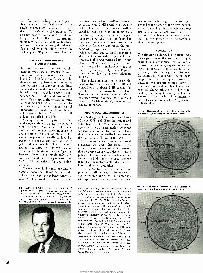
line. By shunt feeding from a 31/8-inch line, an unbalanced feed point with a single end -seal was obtained. This is the only insulator in the antenna. To accommodate the unbalanced feed and to provide flexibility of adjustment, shunt feed in modified delta -match form resulted in a simple, rugged radiating element, which is doubly supported by the heavy -wall 31/8-inch transmission line.
ELECTRICAL PERFORMANCE
CHARACTERISTICS
Horizontal patterns of the radiating ele- ments in free space are essentially omni- directional for both polarizations (Figs. 6 and 7) . The best circularity will be obtained with pole- mounted antennas installed on top of a tower or building. For a side -mounted array, the extent of deviation from a circular pattern is de- pendent on the type and size of the tower. The shape of the vertical patterns for each polarization is determined by the number of layers, magnitude of illuminating currents and their phases, and possible tower effects. Null fill and /or beam tilt is possible.
Although the vertical patterns derive in the conventional manner, principally from the aperture or number of layers, the gain of the BFC- series antennas is about half a unit per wavelength, be- cause the power is equally divided be- tween the horizontally and vertically polarized components. The antennas are built as types BFC -1 to BFC -16, con- sisting of 1 to 16 stacked layers. Spacing between layers is approximately one wavelength and the power gains are from 0.46 to 8.9 respectively for both polar- izations.
The BFC- series is designed for single - channel operation. However, since di- poles are employed as the basic elements, relatively low circulating currents exist,
DR. MATTI S. SIUKOLA holds the degrees of Diploma Engineer (MS) in Electrical Engineering from the Finland Institute of Technology, Helsinki, and Doctor of Philosophy in Electrical Engineering from Oregon State University (1952). From 1946 to 1949 he was employed as a Design Engineer by the
76
resulting in a rather broadband element covering some 2 MHz within a VSWR of X1.3. Each array is equipped with a variable transformer at the input, thus facilitating a simple VSWR field adjust- ment to below 1.1 across the channel in question. Such a low VSWR assures ex- cellent performance and meets the most demanding requirements. The low circu- lating currents due to dipole principle, also result in low voltage gradients and thus the high power rating of 10 kW per element. When several layers are uti- lized, the total rating, however, may be limited by the capability of the 31 /8-inch transmission line to a very adequate 40 kW.
The polarization axis ratio of an ele- ment in free space is about 1.5 dB and a maximum of about 4 dB around the periphery at the horizontal direction. These values represent a good circularly polarized signal to reduce the chances of "no- signal" with randomly polarized re- ceiving antennas.
MECHANICAL CHARACTERISTICS
The BFC design will withstand wind loads of up to 50/33 psf. Both the weight and wind loading of BFC antennas is only about half that of combination antennas for two polarization transmission. Fur- ther economies are realized because of the simpler installation of the BFC.
For environmental protection, good materials are used throughout. The radiator is stainless steel which assures that no corrosion or electrolysis will take place. The end seal is constructed of ceramic, which tends to stay cleaner than other insulating materials, assuring long trouble -free operation.
The large feed systems which are pressurized all the way to the end seals assure reliable operation. BFC antennas with up to seven layers are end -fed. An-
Finnish Broadcasting Corp. to work mainly on AM and FM transmitters and antennas. He also acted as Technical Advisor for the Finnish Government and the City of Helsinki on VHF communications equipment. In 1952 Dr. Siukola joined RCA as a
design and development engineer on television transmitting antennas. He has continued in this field and is presently technical consultant to the TV Antenna Engineering section and leader of the Advanced Development group. He has been in- strumental in developments familiar to the TV
Broadcast Industry, such as: high -gain Superturn- stile antennas, Traveling Wave antennas, Zig -Zag antennas, "Candelabra" installations, and RF pulse analysis of antenna system performance. Dr. Siukola who is listed in the American Men of Science, has
presented and published several papers in his field. He is a member of IEEE, the Professional Group on Antennas and Propagation, Professional Group on Management, Institution of Electrical Engineers, England, Franklin Institute, Phi Kappa Phi, Eta
Kappa Nu, and Pi Mu Epsilon.
tennas employing eight or more layers are fed at the center of the array through a tee. Since both horizontally and ver- tically polarized signals are radiated by one set of radiators, no external power splitters are needed as in the combina- tion antenna systems.
CONCLUSION
The circularly polarized BFC antenna was developed to meet the need for a simple, rugged, and economical FM broadcast transmitting antenna, capable of radiat- ing simultaneously both horizontally and vertically polarized signals. Designed for omnidirectional service, the BFC may be pole mounted on top of a tower or building, or sidemounted on a tower. It combines excellent electrical and me- chanical characteristics with low wind loading and weight, and provides for economy of installation. The antenna is in use by FM stations in Los Angeles and Philadelphia.
Fig. 6- Horizontal pattern of the horizontally polarized signal component in free space.
Fig. 7- Horizontal pattern of the vertically polarized signal component in free space.
www.americanradiohistory.com

A COMPUTER PROGRAM FOR ANALYZING ALTERNATIVE
MAINTENANCE POLICIES A computer program called CO -AMP I (cost optimization and analysis of maintenance policies) has been developed in SEER. Written in Fortran IV for the 7090 computer, CO -AMP I enables a rapid analysis and evaluation of alternative maintenance policies for electronic equipment. Due to the increased emphasis by the military on minimization of operational support cost, it is not only timely that such an analysis tool has been developed, but it is also imperative that this technique be continually improved. This paper presents the purpose of the analysis tool, a brief description of the mathema- tical model programmed, results of its applications, and improvements cur- rently underway.
W. A. TRIPLETT
Systems Engineering, Evaluation and Research DEP, Moorestown, N.J.
HE purpose in formulating CO -AMP 1 I was to provide a rapid and efficient analysis tool in performing trade -offs among the many alternative concepts available for maintenance /logistic sup- port of electronic equipment. Some of the important determinations are:
1) least -cost support concepts for the electronic portions of military weapon systems.
2) optimum module sizes (circuits per module) for various support concepts.
3) most -cost -effective maintenance level for automatic checkout (i.e., built -in versus separate automatic test equip- ment) .
4) conditions under which a discard policy becomes economically feasible.
5) least -cost maintenance policy as a function of such factors as operational reliability, utilization rate, and deploy- ment.
DESCRIPTION OF COMPUTERIZED MODEL
An analytic cost model was formulated to analyze alternate policies of provid- ing maintenance support for electronic equipment. Utilizing this model, a com- puter program was written to 1) accept 45 input parameters related to equip- ment cost, utilization, deployment, test, repair, failure, life, structure, etc.; and 2) compute annual maintenance support costs for manpower, test equipment and procedures, inventory, administration, shipping, and consumed items for up to six maintenance policies in one com- puter run. Also computed are the an- nual cost associated with the prime equipment and the grand total annual cost.
The grand total maintenance support costs are logically divided by the model, as shown in Fig. 1, into seven major
Final manuscript received April $8, 1967.
cost factors: cost of prime equipment (cPE) ; cost of test or troubleshooting equipment (cTs) ; cost of inventory support (civ) ; cost of maintenance man- power (caP) ; cost of supply administra- tion (csA) ; cost of transportation, pack- aging, and shipping (csH) ; and cost of piece part supplies (cPP). The first two are fixed costs and the last five are vari- able. These variable factors relate to the logistics, logistics management, and manpower required on an annual basis to provide maintenance support.
The prime equipment (cPE) consid- ered in the model is specifically that electronic equipment whose purpose is to perform a function in support of a system mission. Since a prime equip- ment is a fixed initial investment, its cost is prorated over its lifetime or over the length of the program, whichever is shorter, to obtain a yearly assessment.
The test and troubleshooting equip- ment (CTS) considered in the model is that equipment utilized to 1) detect the presence of a fault in the prime equip- ment; 2) isolate faults to a specific equipment level (assembly, module, piece part) ; and 3) check out faulty equipment which has been restored, pre- sumably to working condition. The cost for test equipment is included at the organization, base, and depot mainte- nance levels. Since test equipment costs are or can be considered as one -time initial costs, they are prorated to obtain a yearly assessment over the life of the test equipment by the same rule used for CPE.
Inventory support (civ) provides the spare items required to replace and re- pair failed units of prime equipment at each of the various support installations. The spare items in the model include modules, functional assemblies, or sets
WENDELL A. TRIPLETT received the BSEE with high honors from Ohio University in 1950, and the MSEE
from the Drexel Institute of Technology in 1955.
His first six years in engineering included research
on solid state devices, instructing of field engi- neers in electronic equipment, and the design of automatic test equipment for the Sidewinder mis-
sile. Mr. Triplett joined RCA in 1956 as a Project Engineer in the Missile & Surface Radar Division, where he conceived and developed system simula- tions and tests for the Talos Land Based System
and BMEWS. In the Major Systems Division from 1961 to 1963, he functioned in a project manage- ment role in the acquisition of new business, in- cluding the LEM project. Since joining SEER in
September 1963, he has concentrated on the anal- ysis of satellite vulnerability, anti -jam satellite communications and support systems.
depending on the level of sparing or repair policy under consideration.
The total annual cost of inventory sup- port is a function of the number of oper- ational support bases in the system, the annual cost of safety stock at a base, the annual cost for active stock at a base, the annual cost of consumed stock at a base (particularly important when con- sidering throw -away), and the annual costs incurred in reordering spares for a base.
Maintenance manpower (CMP) pro- vides the capability required to perform all manual maintenance support func- tions. The annual cost of maintenance manpower in the model is a function of the number of bases in the system, the annual demand for maintenance actions, the efficiency of the available mainte- nance manpower, the cost of manpower, and the man hours required to perform the necessary maintenance operations. Manpower costs at a base are charac- terized by an annual cost of providing a trained maintenance technician. This cost can be interpreted as including the prorated cost of his training, experience, skill, and any other factors appropriate to the system under analysis. Manpower costs at a depot are characterized by an hourly repair cost.
Supply administration (csA) accounts for the total annual cost of supply ad- ministration; it is a function of the cost of entering a new item into the military supply line and the yearly cost of main- taining it. The cost of initial entry is prorated over the life of the system utiliz- ing the equipment.
77
www.americanradiohistory.com
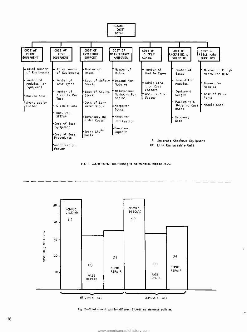
COST OF PRIME
EQUIPMENT
Total Number of Equipments
. Number of
Modules Per Equipment
'Module Cost
'Amortization Factor
GRAND
COST TOTAL
COST OF TEST
EQUIPMENT
COST OF INVENTORY SUPPORT
COST OF MAINTENANCE
MANPOWER
COST OF SUPPLY
ADMIN.
COST OF PACKAGING & SHIPPING
11111 COST OF
PIECE PART SUPPLIES
Total Number -Number of Number of Number of Number of ' Number of Equip- of Equipments Bases Bases Module Types Bases ments Per Base
Number of "Cost of Safety 'Demand for . Demand for
Test Types Stock Modules Administra- tion Cost
Modules Demand for Modules
1 Number of 'Cost of Active ...Maintenance Factors Equipment
Circuits Per Stock Manhours Per Amortization Weight Cost of Piece
Test Action Factor Parts
'Cost of Con- Packaging &
Circuit Cost sumed Stock .Manpower Shipping Cost Module Cost
Costs Rates
Required SCE's* - Inventory Re-
order Costs
-Manpower
Utilization
. Recovery Rate
-Cost of Test Equipment .Manpower
-Spare LRU Support Cost of Test Procedures
* Separate Checkout Equipment
'Amortization ** Line Replaceable Unit Factor
Fig. 1 -Major factors contributing to maintenance support costs.
50 .
40.
30-
20.
10.
MODULE
DISCARD
(1)
(2)
BASE
REPAIR
(3)
DEPOT REPAIR
MODULE DISCARD
(4)
(5)
BASE
REPAIR
(6)
DEPOT REPAIR
BUILT -IN ATE SEPARATE ATE
Fig. 2 -Total annual cost for different SAM -D maintenance policies.
78
www.americanradiohistory.com

Transportation and shipping (csx) provides for the flow of replacement stocks and repaired items from the depot to the bases and failed items from the base to the depot. The cost of packaging and transportation is a function of the number of bases in the system, the de- mand for spares at each base, the weight of the items to be shipped, and the ship- ping cost per trip between base and depot.
Piece part supplies (cri') provides the material for repairing failed modules. The cost of piece part supplies consumed in the repair operation is assumed to be proportional to the number of repairs made (the demand) , the cost of a basic circuit, and a factor which allocates a percentage of the cost of a basic circuit to each piece part repair.
In summary, the computer calculates the following general equation:
GCT = d (cPE) + d (cTs) + ctv CMP + CSA + CSH + CPP
where:
GCT = grand cost total of prime equip- ment and maintenance support annual costs.
d = a pro rata factor to annualize the cost of prime and test equipment.
CPE = cost of prime equipment. CTS = cost of test equipment. CIV annual cost of inventory support.
CMP = annual cost of maintenance man- power.
CSA = annual cost of supply administra- tion.
CSH = annual cost of transportation, packaging and other shipping charges.
CPP = annual cost of piece part supplies consumed in the repair activity.
The computer calculates approximately 38 basic expressions and formulates the sum in accordance with the above gen- eralized expression.
APPLICATION RESULTS
The CO -AMP program to date has been used in analyzing maintenance policies for SAM -D, AAFSS (Advanced Aerial Fire Support System), and the improved ARC -34 communications set.
In the case of SAM -D, three alternative maintenance policies were investigated at the module level : (1) discard faulty modules, (2) repair faulty module in field, (3) repair faulty module at depot. These three are applicable to failure detection either by built -in automatic test equipment (ATE) or by a separate ATE located at the battalion (to accept faulty drawers or functional units for subsequent fault isolation to the module level). Let alternates (1), (2) and (3) be used for the built -in ATE, and let them
be renumbered (4), (5) and (6) for the separate ATE, as shown in Fig. 2.
Fig. 2 summarizes the results obtained in the analysis based on a representative field army deployment of SAM -D. It is seen that policy (2), automatic built -in test down to the module level and field repair, is the lowest cost approach. How- ever, policy 5, separate automatic test at the battalion level of functional units or drawers down to the module level and attendant module repair in the field, is a very close competitor.
A sensitivity analysis was performed for SAM -D maintenance policies by vary- ing 13 different program input param- eters over a range of two octaves about the center value. Ordering of mainte- nance policies with regard to cost was not altered over the ranges examined in the sensitivity analysis, substantiating the earlier findings.
The AAFSS is a high performance heli- copter containing 21 avionic subsystems. The mission is characterized by an ex- tensive forward area deployment. Initial results obtained through use of the CO -AMP program are shown in Fig. 3. The maintenance policies analyzed were the same six outlined for SAM -D above, plus a manual test equipment fault iso- lation policy for two different assumed maintenance personnel skill levels. Main- tenance policy (5) which utilizes sepa- rate automatic test equipment and field repair has the lowest cost, closely fol- lowed by the manual policy for skill level 1. Policy (5) has an additional advan- tage over the manual approach in that fewer skilled maintenance personnel are required.
For the improved ARC -34 communica- tions set, seven different alternative maintenance policies were analyzed, these included:
1) Send the faulty RIT back to depot for repair.
2) Fault isolate to the functional assem- bly at the base and repair the func- tional assembly at the depot.
3) Fault isolate to the piece part and repair at the base.
4) Fault isolate to the module at the base and repair the module at the depot.
5) Fault isolate to the functional assem- bly and throw the functional assembly away at the base.
6) Fault isolate to the module and throw the module away at the base.
7) Throw the faulty set or RIT away at the base.
Nine separate sensitivity analyses were performed for each policy to determine intervals of dominance and cross -over points. The results of two of the sensi- tivity análysis are presented in Figs. 4 and 5. Fig. 4 is the variation of support
cost with set utilization rate, and Fig. 5
presents the variation of cost with set reliability. The ordinate is support cost expressed as a percent of the total prime equipment cost. In the terminology given under the model description
y= d(CTs) +CIV +CMP +CSA +CSH +CPP
d(CPE)
For a set utilization rate of 4.4% (Fig. 4) and an MTBF of 5640 hours (Fig. 5), policy I -depot repair of the R/T to the piece part level with no repair at base - is the dominant choice. These figures also indicate that policy I is far superior to the other policies at set utilization rates up to 50% and over all values of MTBF shown.
PROGRAM IMPROVEMENTS
Based on the experience of using CO -AMP
1 and additional learning in the areas of support system costs, a new program called CO -AMP 2 is under development. This new program will allow the evalua- tion of up to 20 different maintenance policy variations for a weapon system. Some of the salient features being incor- porated in this program are:
1) Provisions for inclusion of develop. ment, acquisition, and replenishment costs for a system.
2) Inclusion, of logistic pipe -line effects with regard to cost and trade -offs be- tween policies.
3) Increased flexibility in the input data requirements for the computer pro- gram.
4) Additional levels of maintenance, which will include equipment, organi- zation, intermediate, and depot.
5) Improved treatment of the determina- tion of safety stock (or back -up spares) through the incorporation of refined lead time computations.
ACKNOWLEDGEMENTS
Although the original CO -AMP 1 program was formulated by the author, with im- portant assistance from a textbook called "Maintainability" written by Goldman and Slattery, much of the analysis of weapon systems and equipment and major improvements (i.e., CO -AMP 2) to the original program have been carried out by other people. For example, B. Cola performed the SAM -D maintenance analysis and A. Messey is carrying out the AAFSS work. W. E. Rapp has been a major contributor in formulating CO -AMP 2 with heavy assistance from A. Messey in the area of program organization and implementation.
The author also wishes to express his thanks to the ASD- Burlington ATE PMO, for their support and encouragement in carrying out the work described herein. 79
www.americanradiohistory.com
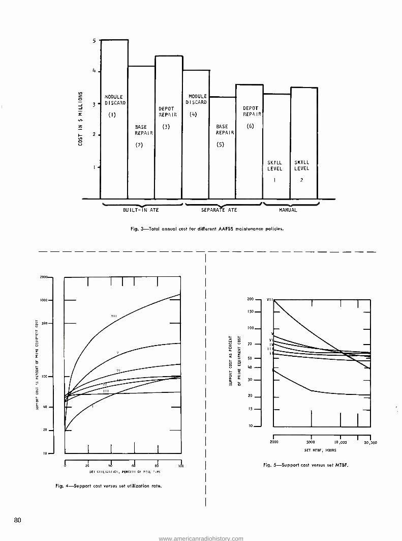
4.
3-
2.
MODULE
DISCARD
(1)
BASE
REPAIR
(2)
DEPOT
REPAIR
(3)
MODULE
DISCARD
(4)
BASE
REPAIR
(5)
DEPOT REPAIR'
(6)
SKILL LEVEL
1
SKILL LEVEL
2
BUILT -IN ATE SEPARATE ATE MANUAL
Fig. 3 -Total annual cost for different AAFSS maintenance policies.
200
1000
500
13 loo
40
20
I0
80
VII
o 20 41 61 81
SET UTILIZATIC'I, PERCENT OF REAL TIME
Fig. 4- Support cost versus set utilization rate.
200
150
100_
70 - 50
ao - 30 -
20
15 . 10
2000 5000 10,000
SET MTBF, HOURS
Fig. 5- Support cost versus set MTBF.
20,000
www.americanradiohistory.com

AN ADVANCED TECHNIQUE FOR VIDEO DATA COMPRESSION
A new video digital data compression technique, Time -Buffered Coarse -Fine
(TB CF), is presented along with experimental results. High -quality video pictures can be produced using this technique with compression ratios, refer- enced to &bit Pulse Code Modulation (PCM), from 2:1 to greater than 20:1
depending on the subject complexity and the element accuracy required, with a typical compression ratio of 6:1. This system uses a modified version of the
Coarse -Fine Compressor invented and implemented by the authors in 1964 with
additional processing of the data by noise -pattern class recognition and removal
circuitry and run -length coding. The Coarse -Fine system is discussed briefly followed by a detailed description of the operation of the Time - Buffered Coarse -
Fine system. Time -Buffered Coarse -Fine compressed pictures are then presented
and analyzed.
SINCE 1963, RCA Astro- Electronics Division has been engaged in R & D
studies concerning the compression of video data to reduce transmission band- width. These studies have led to the invention, fabrication, and evaluation of three new data compression techniques: the Improved Gray Scale PCM' which yields a 3:1, 2:1, or 1.5:1 compression over 6 -bit PCM, depending on the pro- cessing setting selected; the Coarse - Fine PCM' which gives a 2:1 compres- sion with high element fidelity; and the Time -Buffered Coarse -Fine Advanced Data Compressor which yields compres- sion ratios from 2:1 to greater than 20:1 with 6:1 typical.
Data compression is possible because most pictures contain redundant data which need not be transmitted to ex- tract the unique information. Most data compression techniques eliminate or utilize this redundancy to reproduce the vital information at the receiver while transmitting a reduced amount of data. Two classes of data compression tech- niques exist: constant compression techniques in which a reduced but fixed number of bits are transmitted for each sample or picture element, and time - buffering techniques where either the compression obtained depends on the statistics of the picture or where a one - to -one correspondence between picture elements in the original picture and the compressed data stream does not exist. Various analyses of the amount of re- dundancy generally encountered in pictorial information have indicated that compression ratios of about 2:1 over 6 -bit rcM (effectively 3 -bits per picture element) can be obtained using non - time- buffering (constant compression) techniques while reproducing the pic- tures with reasonable fidelity. Time-
WILLIAM T. BISIGNANI
and
GERALD P. RICHARDS
Spacecraft Systems Astro- Electronics Division
Princeton, New Jersey
buffering offers various amounts of re- duction dependent upon the complexity of the pictures involved.
Six -bit PCM, which yields 64 intensity levels, is chosen as a standard since it produces a picture essentially indistin- guishable from the original analog. If fewer than six bits per picture element are used, not only does the accuracy of the picture decrease, but a contouring effect becomes noticeable.
COARSE -FINE DATA COMPRESSOR
Properties
The Coarse -Fine system, an important part of the overall time -buffered com- pressor, is a non -time -buffering tech- nique which gives a constant compres- sion of 2:1 over 6 -bit PCM while providing a high picture element ac- curacy. For pictures of average com- plexity, between 80 and 90 percent of the picture elements are reproduced to 6 -bit accurary and the remaining ele- ments are reproduced to 3 -bit accuracy, with the accuracy of each element identifiable.
In the Coarse -Fine system, the orig- inal signal is digitized to six bits and either the three most- significant bits (coarse information) or the three least - significant bits (fine information) are transmitted. If the original signal is
varying extremely rapidly over a range greater than one -eighth of full scale such
that there is a change in the three most - significant bits at each sample (or pic- ture element), three bits per element are transmitted and displayed as "abso- lute" levels. However, if the signal is varying such that for four or, more successive samples the three most -sig- nificant bits do not change, the three least- significant bits are transmitted and displayed as "relative" levels with re- spect to the most recently received coarse level. An interword coding tech- nique is used to convey to the receiver the Coarse -Fine status changes and hence it is not necessary to consume light levels or add words for signalling. A three -word memory is required at each end of the transmission link and three successive words are compared at all times.
Near -Perfect Pictures
The Coarse -Fine system can be aug- mented to produce a near -perfect pic- ture by a technique called "Coarse Element Refinement," which is accom- plished by sending the fine information for those element positions transmitted in the coarse mode. This added data will decrease the compression ratio somewhat below the 2:1 value, yielding a compression ratio of approximately 1.8:1 for a picture of average com- plexity; however, the reproduced pic- ture is almost exactly the same as the original, the maximum error being 1/64 of full scale for a small percentage of the elements.
TIME -BUFFERED
COARSE -FINE COMPRESSOR
Philosophy
The Coarse -Fine system provides a con- stant non -statistical compression ratio Final manuscript received October 19, 1966.
81
www.americanradiohistory.com

of 2:1 with respect to 6 -bit PCM. The constancy of this compression ratio on an element -to- element basis is a signifi- cant advantage since with a prior knowledge of the compression ratio the storage requirements and net data yield of any system are known fixed quanti- ties and no special buffer storage equip- ment is required at either the trans- mitter or receiver. Constant compression techniques providing compression ratios greater than 2:1 produce significant deterioration in the reproduction; there- fore, further effort was directed toward time- buffering techniques. The large content (80 percent or more) of fine - level signals in a typical ce coded video signal immediately suggests the develop- ment of a redundancy removal tech- nique operating within the CF code but only on fine elements. The realization of this Time -Buffered Coarse -Fine tech- nique involved the solution of two principal problems: the transmitter must contain hardware to define and identify redundant element occurrences; and the occurrence and number of ele- ment removals in the processed data stream must be conveyed in that stream to the receiving decoder.
As a starting point in examining the redundant element removal (RER) cod- ing approach selected, the redundant element identification logic (yet to be described) will be assumed to be pro- ducing successive redundant element identifications which are three to an infinite number of elements in length. A redundant element identification is never produced if it will persist for less than three elements.
The RER signalling logic, having re- ceived a redundant element identifica- tion, defines the first element light level as the run light level. The occurrence of the beginning of an element removal run is then conveyed to the receiver by altering (if necessary) the second ele- ment so that it is identical to the first. The TB CF decoder accepts two succes- sive identical fine words as indicating the beginning of a redundant element removal run. The run light level is
identified by the value of these words. Conflicting occurrences in non- redun- dant fine levels (Le., two words identi- cal but the third unacceptable) are removed in the identification logic by inverting the least significant bit of the second word. The identification logic must operate on the traffic for redun- dancy determination after conflicts have been removed.
The number of removed element po- sitions is conveyed to the receiving de- coder by the signalling logic as a
composite signal of 3 -bit words subse-
82
quent to the run start indicator. N, the number of members in the composite required to describe a run of length R (including the two level indicating words) satisfies the inequality :
3 + log3 (R+2)
4
N. (integer) >
2 + loge (R + 2)
4
where R >_ 3. A composite signal was selected because with such an approach the number of bits required to convey the length of a run decreases as the run length decreases.
Having determined an efficient tech- nique for the conveyance of run -length duration signals, attention can now be directed to the development of a method for identifying signal occurrences which will be accepted as redundant. At least two approaches are possible in that either acceptable information signals or suppressible noise occurrences could be defined. The second alternative ap- proach, that of defining noise, was se- lected because it offers several advan- tages. The statistical nature of the noise and its functional dependencies on such parameters as signal amplitude, time, temperature, etc., are known or deter- minable. The correlation time, i.e., the amount of past history which affects the present, is small and consequently a minimal number of elements must be examined to identify probable noise oc- currences. The most important ad- vantage of the noise definition approach, which is called noise pattern class recognition and removal, results from the fact that the great majority of noise occurrences are small in amplitude; consequently, the occasional erroneous suppression of a signal occurrence as noise will not result in a large light error. The experimental system applies various tests to the data stream allow- ing the continuation of a run until any one or more of the test constraints are violated. The types of tests conducted and constraints applied are discussed in the following paragraphs.
Run Start Test: A run start was made dependent on the relative values of three successive elements present within a small data storage shift register. The run level, when a run was identified, was made equal to the non -conflicting value of the first of these elements. The 3- element re- lation tests may be thought of as ampli- tude apertures. The equipment allowed the selection of one of three apertures: narrow, medium, and broad. The narrow aperture when selected allows a run start only when all three input elements have the same level. The medium aperture when selected permits a run start when the average value of the three element
levels do not differ by more than one third of a quantum step from the level of the first element and neither of the other two elements levels differ by more than one quantum step from the first. The broad aperture when selected allows either or both of the elements subsequent to the first to differ from the first by up to one quantum step of either polarity. For all aperture conditions the first element value, since it is a potential run level, was always made non -conflicting (with CF and run length coding), if necessary, before testing against the run start apertures.
A Test: Noise added to the input analog signal tends to severely reduce the usa- bility or confidence of signal variations equal to or smaller than anticipated noise levels. A good signal -to -noise ratio (which is assumed) restricts this signal -noise confusion to small amplitude variations. The evaluational system, when it has es- tablished a run length signal value, tests this value against each successive ele- ment to determine if the difference is acceptably small. Failure of this test causes immediate termination of the run. The experimental system could be ad- justed to accept any one or more of -i-1, -1, +2, -2 quanta levels (1/64 of full scale) of difference.
R Test. The A test is usually imposed symmetrically about the run light level; thus, if an assumption is made that ± 2 quanta deviations are permitted, the A test would allow a +2 quanta deviation followed immediately by a -2 quanta de- viation. Such large differences between successive elements is not compatible with the assumption of small noise levels. Be- cause of this intrinsic weakness of the A test, the system also imposes an R test which terminates a run if an excessive rate of change exists. The acceptable magnitude of successive differences can be adjusted to 1, 2, 3, or 4 quantum steps.
L Test. As was mentioned in the discus- sion of the A test, noise tends to create a region of amplitude confusion between signal and noise occurrences. Amplitude deviations within this region are probably noise if they are random but are almost certainly caused by signal if they are well ordered, such as successive elements all having the same polarity of deviations from the established run light level. In the experimental system, when several successive elements are found to deviate from the run light level all in the sane direction (polarity), the run will be ter- minated independent of the magnitude of such deviations. In the experimental sys- tem, the length of permissible successive element unipolar deviations can be ad- justed from one to seven or can be set to infinity by a defeat switch. In addition, an L. constraint operating on successive 2- quanta unipolar deviations is included. This L. constraint is separately adjustable and has meaning, of course, only if the A test constraint permits two quanta de- viations. Ideally, failure of an L test should cause termination of the existing run at the beginning of the lengthy de- viation. The additional in- process storage and double processing tof the deviant elements) implied by this ideal was judged excessively expensive; conse- quently, in the experimental system, the run length was terminated for L test failure at the element producing the ex- cessive length.
www.americanradiohistory.com

rORIGINAL C -F ENCODER
COARSE 3 -BIT
REGISTER
ANALOG VIDEO
IN
11
6 -BIT A/D
CONVERTER
FINE 3 -BIT
REGISTER
L
COARSE EXAMINATION
REGISTER
CONTROL LOGIC
S T SGNAL rl S
3 -BIT REGISTER
SELECT GATES
i
3 -BIT FINE MEMORO
REGISTER
3 -BIT DELAY
REGISTER 3
3 -BIT DELAY
REGISTER
MEMORY REGISTER INPUT
SELECTION GATES
3 -BIT DE AY
REGISTER 2
CONFLICT IREFI REMOVAL
LOGIC
PREVIOUS WORNEW D WORD ITO RBI
FROM ROI
1 1
OUTPUT SELECTION
GATES
f DELAY REG 3
REDUNDANT ELEMENT
MARKER BIT
t DELAY REG 2
REDUNDANT ELEMENT
MARKER BIT
DELAY REG I
REDUNDANT ELEMENT
MARKER BIT
DIGITAL FILTER AND
CONTROL LOGIC
Fig. 1- Time -buffered coarse - fine experimental encoder,
block diagram.
Fig. 2- Experimental test facility, block diagram.
35 -MM TRANSPARENCY
FLYIN -SPOT SCA NER
LOW PASS FILTER AND
D -C AMPL
6 -BIT A/D
CONVERTER
T- B
C-F
1
6 BIT
VERTICAL AND
HORIZONTAL SONO GEN
PRINT 35 -MM TRANSPARENCY
3 BIT
DATA PATTERN
GENERATOR
3 -BIT PCM
SELECTOR
TIME -BUFFERED COARSE -FINE
ENCODER
35 -MN CAMERA
KINESCOPE
DISPLAY
6 -BIT DMA
CONVERTER
TIME -BUFFE RED
COARSE -FINE DECODER
IL
REDUNDANT WORD !DENT FICATION
TOTAL OF WORDS
NO OF FINE WORDS
ORE -SET COUNTER (SET TO I FRAME
OR SELECTED PORTION THEREOF) COUNTER
ON -OFF COMMAND
NET WORDS DELETED
COUNTER
IDENTIFY RUN
CODE WORD
POSITIONS
GERALD P. RICHARDS received the BS and MS
degrees in electrical engineering from the Massa- chusetts Institute of Technology in 1953 and 1955
respectively. During 1955 Mr. Richards was em- ployed as MTS at the Bell Telephone Laboratories. Upon return from military service in 1957 he joined the ITT Laboratories in Nutley, N.J. where he per- formed developmental work on RTL and tunnel diode logic elements. Also at ITT he held overall systems responsibility in the design of a large solid state switching system. In 1961 Mr. Richards joined the Astro- Electronics Division. From 1961 to
1963 he designed special digital data processors. In 1963 Mr. Richards joined the Spacecraft Systems
group where he is presently a senior engineer. In
this position he has contributed in broad areas of
data processing including low carrier frequency FM
techniques and high noise FSK and many analysis. Throughout this period he has e.tens lively con- tributed to design reviews as principal reviewer. A large portion of his time since 1963 has been devoted to the digital TV compression effort. His efforts produced the Improved Gray Scale logic, the concept and logic of the Coarse -Fine system, and the concept and basic logic of the TB CF system. Mr. Richards is a member of Sigma Xi and IEEE.
WILLIAM T. BISIGNANI received the BS and MS
degrees in electrical engineering from Rutgers University in 1961 and 1962. After summer positions at Bell Telephone Laboratories, Electronic Asso- ciates, and Federal Pacific Electric Company, he
joined the Astro- Electronics Division of RCA, Princeton, in 1962. At RCA Mr. Bisignani is associ- ated with the Systems Engineering and Advanced Projects section where he has been associated with the RANGER, TIROS, NIMBUS, VOYAGER and World Weather Watch programs. Since the begin- ning of 1964, Mr. Bisignani has been lead engineer on the division's data compression research pro- grams where he has contributed to the develop- ment and evaluation of the Improved Gray Scale, the Coarse -Fine, and the Time- Buffered Coarse -Fine data compression systems. He is co- author of three published papers on data cernp-ess on systems in-
cluding an article in the March, 1966, Proceedings of the IEEE. Mr. Bisignani is a member of Tau
Beta Pi, Eta Kappa Nu, and Pi Mu Epsilon.
83
www.americanradiohistory.com

System Implementation
The purpose of the processing logic constructed was the evaluation of com- pression ratios and statistics, and the production of recovered images which are identical to those which would be produced in the complete time -buffering system. To satisfy this purpose, actual redundant element removal and format- ting of run -length code words were not required. The logic necessary to ac- complish the desired goals need only consist of an augmented CF encoder (Fig. 1) , and a normal unmodified CF
decoder` since all processing could be performed on a one -to -one input - output element real -time basis. The augmentation logic shown in Fig. 1
operates only during the fine -data mode of the CF encoder, performing the two functions of redundant element identi- fication and the removal of all data stream conflicts with run -length code words. This latter function was per- formable since data -stream conflicts are not influenced by the values of run - length words which would be inserted in a complete system.
Redundant -element identification is performed by a logical realization of the entrance aperture, A, R, L, and L2 constraints as illustrated in Fig. 1. Ap- plication of these constraints requires the availability of three elements of data (from the delay registers) and the continued availability of the selected run light level (circulated in the fine memory register) . Final identification of redundant elements in the delay register data stream is provided by a marker bit from the control logic. The output selection gates, under the com- mand of this marker bit, provide as the final encoder output either the final delay register (not redundant) or the previously produced element (redun- dant). Thus, without the removal and reinsertion of redundant elements, a CF-
coded equivalent to an actual TB CF
data stream has been formed.
EXPERIMENTAL TEST FACILITY
To experimentally evaluate the TB CF
compression system, the experimental test facility, (Fig. 2) was constructed. This system can be divided into three groups: input- output equipment, control and data -gathering equipment, and com- pression- system -checkout equipment.
Input- Output Equipment
The input equipment used to generate the 6 -bit digital signal required by the TB CF encoder consists of a flying -spot scanner, a low -pass filter, an amplifier, and a 6 -bit analog -to- digital converter.
84
The flying -spot scanner converts any 35 -mm transparency into an analog sig- nal by scanning the transparency using a 5ZP16 kinescope. Manual triggering produces only one frame at a time; each frame period is approximately 34 seconds. The analog signal in each frame consists of 667 -by -512 elements sharply filtered to a bandwidth of 5 kHz. The signal is supplied to a 6 -bit analog -to- digital converter which pro- duces a 6 -bit quantized signal at 10,000 words /second, the Nyquist sampling limit. This 6 -bit signal can be sent to the output device for direct display as either a 6 -bit or 3 -bit PCM picture, or to the TB CF chain for processing. The output device consists of a 6 -bit digital - to- analog level converter, a 5ZP16 kine- scope display, and 35 -mm kinerecording camera.
Control and Data -Gathering Equipment
The TB CF data compressor is designed to allow various processing parameters (A, R, L, and L2) and entrance aper- tures (narrow, medium, and broad) to be varied independently over a suffi- ciently large range to allow evaluation of their effects. The equipment em- ployed to gather the required data is capable of examining any horizontal section of the picture up to and includ- ing an entire frame. Data taken for those parameters which require the in- sertion of run -length code words is automatically adjusted during measure- ments to yield net -not gross- redun- dancy. The important parameters ob- tained are the TB cF compression ratio and the number of elements transmitted in the fine mode (of the CF system).
The TB CF compression ratio can be obtained from the formula:
Compression Ratio - 6N, 3 (N,- Nd)
where both Nd, the number of words in the section to be deleted from the data stream before transmission, and N,, the total number of original 6 -bit words out of the AID converter in the section, are measurable quantities.
The number of elements transmitted in the fine mode is an indication of the compressibility and the accuracy of the section. This quantity permits the de- termination of compression loss result- ing from the inclusion of coarse ele- ment refinement (cut).
System Checkout Equipment
A digital -data- pattern generator was de- signed to simulate A/D-converter output
data. Careful analysis of theoretical compressor operation allowed the de- termination of a 32 -word data pattern capable of exercising all TB CF com- pression functions. Periodic substitution of this data simulator at the encoder digital input provided assurance of cor- rect compressor operation.
EXPERIMENTAL RESULTS AND EVALUATION
Test Conditions
The analog output of the flying -spot scanner was adjusted so that the black - to -white signal swing for each subject encompassed all 64 levels of the A/O converter. This choice of maximum signal range was found to minimize the available compression. To illustrate the increase in the compression ratio that would occur with a reduced black -to- white signal range, as would be the case for most space missions, the nebula photo was processed with 0.6 of full signal range into the A/D converter. Under this condition, the compression ratio in- creased by 50 percent over that using the full signal range.
Experimental Results
Lunar photographs (Fig. 3) were se- lected as representative of subjects that might be obtained in an interplanetary mission. Since little a priori informa- tion exists, the viewer is required to compare the compressed pictures to the original 6 -bit representation. The TB CF
compressor produced excellent results on this subject as can be seen in Fig. 3a through j.
A picture with a 5.9:1 compression ratio (shown in Fig. 3b) over the 6 -bit representation (shown in Fig. 3a) was obtained when using the TB CF system. This compression ratio is equivalent to about one bit per sample, yet the pic- ture details are accurately retained and essentially no degradation can be noticed. For this sample, the system parametric constraints are: medium en- trance aperture, A = -2, L = 7, L2= 3, and R = 4. By relaxing the con- straints to broad entrance aperture, 0= ±2,L =L,= oo, and R = 4, the compression ratio is increased to 6.94:1. This result, shown in Fig. 3d, indicates slight degradation. Long lengths of the same gray level appear in large areas of little detail; notice, however, that the sharp details such as small craters are retained since the system distin- guishes these as information. A com- parison with the 3 -bit PCM representa- tion (Fig. 3c) (always recoverable from the TB CF signal) shows that the com- pression effects occur only in large
www.americanradiohistory.com

areas of constant coarse level as would be expected. To produce a higher ele- ment accuracy representation of the original 6 -bit picture, the constraints were tightened to: medium entrance aperture, A = -!-1, L = 3, L, = 0, and R = 4. This produces the picture shown in Fig. 3e with a corresponding compression ratio of 4.6:1. Maximum constraints of narrow entrance aperture, A = 0, L = L, = 0, and R = 0, pro- duces a nearly pure Coarse -Fine repre- sentation while still yielding a compres- sion ratio of 2.86:1 as illustrated in Fig. 3f.
Other important data statistics were obtained for the lunar photograph. One of these data sets provides compression ratio measurements for ten adjacent horizontal sections of the picture. The results shown in Fig. 4a and b for two groups of parametric settings illustrate that the upper sections (low activity) yield about 50 percent more compres- sion than the lower sections (high activity).
Nebula compression results are pre- sented in Fig. 5. The results with the constraints of broad entrance aperture, 0 = ±2,L= cc, L,= cc, and R =4, shown in Fig. 6b, compares favorably with the 6 -bit PCM results shown in Fig. 5a. Essentially all of the stars were
Fig. 3 -Lunar photographs.
reproduced using the TB CF system, which provided a compression ratio of 6.28:1.
The 6 -bit representation of the nebula shown in Fig. 5c, has a video signal range of 60 percent of the A/o con- verter range; i.e., about 40 of the 64 possible intensity levels. Fig. 5d, pro- duced by the application of compression to this reduced input signal, shows a compression ratio of 9.54:1 with con- straint settings identical to those used to obtain Fig. 5b.
Data Refinement
Because of the basic nature of the Coarse -Fine system, the TB CF data can also be augmented to include the fine information of its coarse element con- tent. Although no photographs of such augmented TB CF could be made be- cause of equipment limitations, the coarse content of some photographs was measured to allow calculation of avail- able augmented TB CF compression. A comparison of compression available if fine augmentation were to be added to the photographs is presented in Table I. The growth in compression loss at high initial TB CF ratios is of little conse- quence since data accuracy require- ments necessitating augmentation would not permit the relaxed run restrictions required to produce such high com- pressions.
a. 6-BIT PCM b. COMPRESSION RATIO 5.9:1 (CONSTRALNTS:APERTU RE M, A= =1, I¡ 3, L¿= 0, Rte)
c. 3-BIT PCM d. COMPRESSION RATIO 6.94U (CONSTRAINTS -APERTURE R, A= =2, L= _0, 1.2= R= 4)
e. COMPRESSION RATIO 4.6:1 (CONSTRAINTS: APERTURE M,
A= t1, L =3, L, =O, R =4)
I. COMPRESSION RATIO 2. 86:1 (CONSTRAINTS: APERTURE N,
A- 0, L= 0, L,= 0, R= 0)
COMPRESSION (5
11.57
12.98
2.52
1.45
)
9.04
7.40
6.87
7.41
9.02
11.74
TABLE I,- Compression of Lunar Photo Available with Augmented TB CF with 88.5 Percent of the Elements in Fine Mode and 11.5 Percent of the Elements in Coarse Mode.
Initial TB CF
Compression Ratio
Net Augmented TB CF
Compression Ratio
2.86 :1 4.6 :1 5.9 :I 6.94:1
2.45 :1 3.64 :1 4.40 :1 4.96:1
CONCLUSIONS
The photographic and numerical evi- dence obtained demonstrates that appli- cation of the Time -Buffered Coarse -Fine concept can in fact produce excellent results both in reproduced picture quality and in the degree of compres- sion available. Compression ratios from 4.5:1 to 6.3:1 have been obtained with excellent quality. Even higher compres- sion ratios are possible if a somewhat lower quality reproduction will suffice. The most effective control was found to be the L constraint which could minimize or eliminate the streaking effect evident in many forms of statis- tical compression.
BIBLIOGRAPHY 1. W. T. Bisignani, G. P. Richards, and J. W.
Whelan, "The Improved Gray Scale and Coarse -Fine PCM Systems. Two New Digital Tv Bandwidth Reduction Techniques," Proceed- ings of the IEEE, March, 1966, and the 1965 IEEE International Convention Record, Part 4.
(5) COMPRESSION
12.34
11.89
2.17
12.02
10.16
8.04
7.78
8.09
9.15
9.36
a. CONSTRAINTS: APERTURE N, b. CONSTRAINTS: APERTURE B, A =O, L =0, L, =0, R =0 A =a 2, L =W. 1., = R =4
Fig. 4- Distribution of compression in Lunar photographs for two groups of constraint settings.
a. FULL A/D SIGNAL RANGE, 6 -BIT PCM
d. 60% A/D SIGNAL RANGE, COMPRESSION RATIO 9.54:1; (CONSTRAINTS: APERTURE B, A = 42, L =O', L, =m, R =4)
b. FULL A/D SIGNAL RANGE, COMPRESSION RATIO 6.28:1 (CONSTRAINTS: APERTURE B; A =62, L =m. Lx =m. R =4)
c. 60%, A/D SIGNAL RANGE, 6 -BIT PCM
Fig. 5-Nebula photographs.
85
www.americanradiohistory.com

Engineering and Research NOTE S BRIEF TECHNICAL PAPERS OF CURRENT INTEREST
Dollars versus Protection in Destructive Testing
D. S. WRIGHT, Product Assurance Astro- Electronics Division
DEP, Princeton, N.I.
Final manuscript received Marsh 14, 1967.
Destructive test sampling differs from any other sampling in two very important ways: it is more expensive and the disposition of rejected lots is different. Ordinarily, a rejected lot can be screened or tested 100%. With destructive testing this is impossible; hence the average outgoing quality limit (AOQL) concept of sampling (predicated upon the 100% sorting of rejected lots) is lost.
How large a sample should we take for a destructive test? A frequent solution is to pick out some small number like 3 pieces, and to allow zero defectives. Another answer is to pick up one of the S -level plans of MIL -STD -105D (for expensive testing) and then select some safe -sounding acceptable quality level (AQL). Such an action has a certain psychological defense: one is sup- posed to take a sample before accepting anything -and now one has done this. But in selecting a sampling plan intelligently, two important questions arise: 1) What protection of quality should the plan give? Specifically, what consumer's and /or producer's risk are we willing to take and for what quality level? 2) What is the total cost of the testing? The relation of protection of qual- ity to cost is the important consideration in choosing a plan.
How this can be done is best illustrated by taking a specific case and constructing a cost model. As an example we can choose a plan for acceptance sampling of a pyrotechnic device. These devices cost $100 each in lots of 1000; testing costs $10 each. In this case, it has been decided that the protection afforded by MIL -STD -105D, level II, 4% AQL is adequate. Since the AQL is concerned with producer's rather than consumer's risk, we con- sult MIL -STD -105 and find that this plan would provide a 10% probability of accepting lots which are 14.2% defective (in Dodge - Romig nomenclature, lot tolerance percent defective (LTPD) of 14.2% for beta of 0.10). One other factor enters into consideration: What quality of lots will be presented to our inspection plan for acceptance? Since we have no way of knowing this, and since it will affect costs, it will he necessary to compute costs over a wide range of incoming lot quality (Process Average).
The basis for comparing the various sampling plans is the total cost /good unit accepted. Some of the elements involved are the lot cost of 1) purchasing (including handling, etc.) 2) testing, and 3) rejection. It is assumed that rejected lots cannot be used and are not returnable to the vendor; their cost is chargeable against the sampling plan. Since we are comparing various plans on the basis of providing the same consumer protection, this serves to penalize a plan which would reject an inordinately large num- ber of lots in order to provide that protection.
The net cost of testing /usable unit accepted is:
CTU = NC, + CT C
PA (N - n)
86
3 20
10
1698 1361 .3
/ / i i'
i ---------_
- SINGLE SAMPLING
Fig. 1 -Test cost versus incoming quality for single, double, and multiple sampling.
where N is lot size (1000 for the present case) ; n is size of sample tested (or average sample number) ; Cu is unit cost of acquiring item (purchase price + overhead and handling -$100 in our example) ; CT is unit cost of test operation (including overhead -$10 for this example) ; Cru is net unit cost of testing, per usable unit acceptable; and PA is probability of acceptance of the lot under the plan in question.
The denominator is the expected number of usable pieces that will be realized from each lot. The numerator is the total cost of acquiring and testing a lot.
Assume an incoming lot quality of 4% defective, using MIL - STD-105D, level II, single sampling. From that table, n = 80. Probability of acceptance is computed to be 0.982.
Thus,
Cru -_ (1000 X $100) + (80 X $10) $100 - $11.58 0.982 (1000 - 80) -
Applying the same formula to lots of incoming lot quality ranging from 1% to 15% defective results in the graph shown in Fig. 1. Cost goes up sharply as the incoming lot quality exceeds 8% de- fective, due to the large number of lots being rejected and in- cluded in the total cost. Repeating the computation with the corresponding MIL -STD -105 double and multiple sampling plans yields the data graphed in Fig. 1. Now, however, the average sample number (instead of sample size) is used for n. The double and multiple plans are substantially lower in cost for good incoming lot quality, because the single plan has a large fixed sample size. Double and, to an even greater extent, multiple plans will accept a very good lot with a much smaller sample. A sequential plan has been developed to match as closely as possible the MIL- STD -105D plans in consumer protection since a sequen- tial plan will provide a given level of protection with an even smaller sample. Table I shows the formulas and cost computa- tions. A matching chain sampling plan was also developed. These are graphed in Fig. 2.
Fig. 2 -Test cost versus incoming quality for sequential and chain sampling.
-7 7. 60
1780
v¢anxc Lo. wuTT ,rcncc.T ocTCC*rv¢1
www.americanradiohistory.com

uo
100
90
ú 60
- 10
60
ú 50
40
30 -
20 - L STD 05 0 LEVEL II - SEQUENTIAL PLAN
10 - --A- -- MIL -STD 105-13 LEVEL 52 - -MIL -ST D los -D LEVEL SO
e
INCOMING LOT QUALITY (PERCENT DEFECTIVE)
Fig. 3- Operating characteristic curves.
The question is often asked: For destructive testing, why not use the MIL- STD -105 S -level plans? Since these use much smaller samples, it was decided to compare them with the plans above, even though their consumer protection was drastically poorer than that demanded. The results were that the costs are about the same as a sequential plan for 1% lot quality, higher for 2% and 4% lots. Only when lot quality becomes worse than 4% are they cheaper, and then only because they accept a very high percentage of inferior lots. Their spectacularly poor consumer protection is shown in Fig. 3, comparing operating characteristic curves of the plans above.
Summarizing, the requirement of lowest cost demands rejecting the fewer possible number of lots while holding a stated level of consumer protection. This calls for a plan with a high discrimina- tion (low operating ratio) and also for holding down sampling size. These two requirements seem to be incompatible: a high degree of discrimination is usually associated with large sample sizes. However, as we have shown, use of multiple or sequential plans will, for a given level of protection, require the smallest possible sample size.
If the situation allows the use of variable instead of attribute sampling, greater economy may be effected. Each sample piece tested for a variable response yields more information than a piece tested for an attribute. Hence the necessary information can be gleaned from a smaller sample.
An alternative to destructive sampling may be the use of a non- destructive test which correlates highly with the destructive test. If this can be found, it is especially valuable as a means of sort- ing (screening) rejected lots for good pieces.
Choice of a sampling plan for a destructive test need not be a matter of choosing some arbitrary number, or of picking a plan blindly from a table. A systematic approach calls for the following steps: 1) Define the parameters and conditions of the problem; 2) Establish the costs of each element; 3) Formulate a mathe- matical expression for the cost; 4; Using that expression, plot the costs versus incoming lot quality for various types of plans; and 5) Choose the best plan for the case at hand.
Two valuable alternatives are also worth consideration: 1) Find a correlating nondestructive test; or 2) Use variables sampling instead of attributes.
Armed with this approach, the cost -to- protection ratio can be optimized for any set of conditions. Acknowledgement: This paper appeared originally in the Techni- cal Convention Transactions of the American Society for Quality Control Annual Convention, May 1967.
BIBLIOGRAPHY: 1. United States Department of Defense, Mi liter?, Standard, Sampling Pro-
cedures and Tables for Inspection by Attributes (MIL- STD- 105D); U.S. Government Printing Office, Washington, D.C., 1963.
2. Harold F. Dodge and Harry G. Romig, Sampling Inspection Tables - Single and Double Sampling, 2nd Ed.; John Wiley and Sons, Inc., New York, 1959.
3. A. Wald, Sequential Analysis, John Wiley and Sons, Inc., New York, 1947.
4. Harold F. Dodge, "Chain Sampling Inspection Plans ", Industrial Quality Control, January 1955, pp. 10 -13.
5. Acheson .1. Duncan, Quality Control and Industrial Statistics, 3rd Ed.; Part II, "Lot Acceptance Sampling Plans ", pp. 145 -294; Richard D. Irwin, Inc., Homewood, Ill.
TABLE I- Sequential Plan to Match MIL -STD -1O5D, Level II, 4% AOL Single Sampling Plan (N - 1000)
1% Incoming Lot Quality
2% 4% 8% 15%
Prob. Ace. f ' ; 99.9 99.9 98.2 63.0 7.5 Average Sample 21.0 21.0 38.0 63.0 36.0 Net unit 'list Cost (9) 2.35 2.36 6.22 70.56 1293.88
Where (SN = average sample number, a = Producer's Risk, /1 = Consumrz's lt(OIL. I">_ = Imt quality corresponding to a, and P's = lot quality correspond- ing to/l:rr= 1.8 %;/3= 7.5 %;P't =0.04; and P', =0.15
l0 1 -a 1 -
l0 fl
g /1
tr /":: (I I ",) = 2.73
P4 (1 -P's) hi = _1.75
logPs(I-I"T) P'r(1-P'2) (I -
log S= (1-P'2)
log Pa - (1 PS) P'i(1 -P'_)
= 0.0841 A, = -1.78 + 0.0841 n (Accept Line)
V = 2.71 + 0.0841 Ti (Reject Line)
PA log (1()a) + (1 - PA) log (1 (a)R) 05N =
1 "s (1 - 1"2) P' +(1- P')log (1 -PS)
Mechanized Reflow Soldering of
Flatpack Integrated Circuits
J. W. KAUFMAN
Central Engineering Defense Electronic Products
Camden, New Jersey
Final manuscript received February 27, 1967.
Reflow soldering is the fusing together in assembly of the solder which has been pre- coated on the parts to be joined. This fusing together is in the nature of a "sweated" solder joint.
For electrical attachment from only one side (surface attachment) the integrated circuit rests on the circuit board so that the leads form lap joints with the circuit board pads.
The mechanized reflow soldering method employs a heated wedge - shaped soldering tip that contacts all of the leads of an integrated circuit at one time. Inasmuch as the heat is applied externally (as with a hand soldering iron) no electrical damage can occur to the semiconductor, providing known precautions are taken with respect to leakage and grounding. The temperature of the soldering tip is controlled by a fool -proof means so that no damage can occur from overheating. Mechanized means are used to apply the soldering tip, control the time, and hold the soldered joint until it solidifies.
A thermo -magnetic temperature controlled hand soldering iron, that utilizes the Curie Temperature of an alloy slug in the soldering tip to make and break the electrical circuit, had already been mar- keted.* (The Curie Temperature is the temperature of magnetic transformation below which a metal or alloy is magnetic and above which it is paramagnetic.)
A wedge- shaped tip of this type, having the prescribed size and shape for the particular job at hand, was designed and fabricated. In fact, several tips were built to permit experimentation wills the variables of time and temperature. Due to the intimate thermal path provided by the heat source, the author found the most efficient operation with a 700 °F tip, impressed on the leads for 2 seconds. Figs. 1 and 2 show a working feasibility model. A description of this model follows: The device uses a specially designed wedge soldering tip that spans all the leads over nominally a 0.250 inch span with a width of flat section of about 0.030 inch, large enough to set down on the flat of the lead. The tip is heated to a specified temperature, controlled by a Curie Temperature sensing device in the tip. The tip is impressed on the leads for a specified period of time, then raised. Before application of heat, a specially -designed spring member forces the leads flush against the circuit on either side of the soldering tip. As little as 0.050 inch total space may be available for the tip and springs together. The tip comes down, reflows the solder, and is released while the springs remain in place until the joint solidifies. Then the springs are raised. The springs serve the two -fold purpose
87
www.americanradiohistory.com

of holding the joint in place until the solder solidifies, and acting as a heat dissipator to prevent overheating of the intergrated circuit. The springs are lined with a thermally -insulating plastic film (H- Film or Teflon). This film also acts to provide lubricity With the soldering tip. This device can he timed so that all actions are mech- anized, and the part to be soldered can be moved from position to position. Also, a multiple device can be arranged to reflow solder all of the leads on both sides of the integrated circuits at one time. Further, a multiple device can be arranged to reflow arrays of leads of several integrated circuits at one time.
An auxiliary technique employs a plastic to tie down the body of the integrated circuit so that all the integrated circuits can be pre -placed with the leads in position at an assembly station before the reflow operation begins. Dow 271 or equivalent can he used. This material was found to be ever -plastic so that final dimensional adjustment, if required, can be made at the work station. A solder- ing tip of greater width can be provided for integrated circuits with more than five leads on a side.
Recommended preparation of the parts to be joined is to have at least one surface flat, so that the parts do not slide wih respect to each other during the plastic flow of the solder. Although the leads of the integrated circuit may be dip soldered, the solder coating on the circuit hoard should be quite thin to avoid the displacement of the integrated circuit lead with respect to the circuit pad during the reflowing.
In the demonstration, the integrated circuit leads were pre -solder dipped, and the etched circuit board was solder electroplated. The body of the integrated circuit was preplaced on the circuit board with a plastic adhesive that permitted final adjustment of the leads with respect to the circuit board pads. A single drop of Dow 271 applied with the edge of a toothpick or similar applicator was placed on each part to be joined. The parts were allowed to set for fifteen minutes before placing them together. Final adjustment was made at any time thereafter, positioning the leads with respect to the circuit pads. The assembly was fluxed with an activated rosin flux, conforming to MIL -F- 14256, Type A. The author was successful with the use of this flux brushed over the assembly and permitted to air dry or about fifteen minutes before reflowing.
Upon applying the tool to the joint, the first apparent indication of reflowing will be the activation of the flux. Subsequent to the flowing of the flux, the solder will reflow. The solder reflow will be visually observable under the magnifier. An acceptable soldered connection as made, is shown in a representative macrophotograph (Fig. 3). Smooth solder fillets ( criteria for suitable soldering are observed. A representative metallographic cross- section is shown in Fig. 4, at 100 magnifications. A smooth solder transition is shown. This admittedly simple working model proved the feasibility of rapid reflow soldering by an externally -applied heat source.
From this concept, a production machine designed for high speed reflow soldering of adequately pre -tinned surfaces has been mar- keted. The machine is an efficient and economical production method of interconnecting flat pack integrated circuits and printed circuit boards. Efficiency and economy are achieved by the unique method of soldering a complete flat pack (all leads on both sides) in one single operation. Two soldering tips of sufficient width to accommodate the various multi -lead flat packs are indirectly heated using the thenno- magnetic temperature control system. The flat packs are placed in a holder which aligns the component with the circuit pads, and acts as a heat sink. Alternatively, equipment mod- ification permits pre -placement of the flat packs, and the holder serves the single purpose of a heat sink. A foot switch then activates an automatic soldering cycle, during which the tips are lowered to the work, dwell, and return to their retracted position. Wettable soldering tips are used to provide the most efficient thermal path between the tips and the work area. The heating elements are low voltage (24 volts), which insure long life. All parts of the machine, which contact the work or operator, are grounded. The total time needed to position the flat pack and to complete the soldering operation is a few seconds, dependent on the dwell time of the soldering tips, which is adjustable from less than 1 second to 6 seconds.
RCA Missile and Surface Radar Division recently has completed an order for a series of integrated circuit modules for a large ground support space system for the Burlington Plant. The soldering of the flat packs to the hoard circuitry was performed with the solder- ing machine. As reported by the Manager of Manufacturing En- gineering, Mr. J. P. Stratton: "The operation was most successful, producing good quality solder joints at acceptable cost." The time to attach a flat pack is in the order of a minute compared to an average 15 minutes for hand methods. Furthermore, additional time (cost) savings can result from more experience in use of the machine and from the decreased amount of repairs required. Re/ererrre: It. G. Clarke and and J. W. Kaufmn, "Packaging High -Density Circuits," A.esenrblu Enyineerieg, June 1966.
88
Fig. 1 -Reflow soldering tool.
Fig. 3- Macrophotograph showing all leads on one side of a flat pack soldered with the feasibility model.
Fig. 2- Close -up of r
soldering tool.
Fig. 4- Photomicrograph of cross -s.
of an individual solder lead, showir smooth solder fillet and excellent bond.
Fig. 5- Wel'-er integrated circuit soldering machine. (The author has the permission of the Weller Electric Company for using the description of their equipment.)
www.americanradiohistory.com

COMPREHENSIVE SUBJECT- AUTHOR INDEX
to
RECENT RCA TECHNICAL PAPERS
Bor^ publisFed r.,pers acd verrs,1 F- ---,t T o -an p,,rHshed paper. bcsrow 'Fe [curl- al n wh, k t at T _ br , ethc -., et- For efo ^_,h:. . - F b rri .erE, present r. wrIF ,r ca -he , h r, (Thy, utH r RCA Dl,rel o -pI> -i _; L, -,It his r e the
ub ¡c.- t -ndez ent-y l For add ' .. _ RCA : to -, _ . .rq err - r,tre -ontect: RCA Staff Technical Publications, Bldg. 2 -8, RCA, Camden, N. J. (Ext.
PC- 4018(. This )ndes is prepared from (stings prodded bimonthly by RCA Divlslon. Technical
Publications Admlnistrators and Editorial Representatl yes -who should be contacted concerning errors or omissions (see Insde back coven.
Subject index categories a e based upon the Thesaurus of Engineering Terms,
Engineers Joint Council, N. Y., Ist Ed., May 1964.
SUBJECT INDEX Titles of papers are permuted where necessary to bring significant keyword ls) to the left for easier scanning. Authors' division appears parenthetically after his name.
ACOUSTICS (theory 8 equipment)
ACOUSTICS EFFECTS, Speech Recognition and -W. F. Meeker (CSD, Cam) Chap. 3 -1 of Communication Systems Engineering Hand. book, McGraw -Hill, N.Y., 1967
ACOUSTICAL PHONON DETECTOR, Sensitive Tunable -C. H. Anderson, E. S. Sabisky (Labs, Pr) Phys. Review Letters, Vol. 18, No. 7, 2/13/67
ANTENNAS
CIRCULARLY POLARIZED FM ANTENNA, New -R. E. Winn (BCD, Gibbs) Georgia Assoc. of Broadcasters (GAB), Pine Mountain, Ga., 6/19/67
PHASED ARRAYS, A System Designer's View on Tubes for -Dr. J. T. Nessmith (MSR, Mrstn) 3rd High -Power Microwave Tubes Symp., Ft. Monmouth, N.J., 5/24-25/67
CIRCUITS, INTEGRATED
AUTOMATED MASK PRODUCTION for Semi- conductor Technology -H. O. Hook (Labs, Pr) 1967 IECI-IEEE One Day Symp., Phila., Pa., 6/5/67
EXTENDING IC TECHNOLOGY to Microwave Equipment -H. Sobo) (Labs, Pr) Electronics, 3/20/67
INTEGRATED CIRCUITS for Consumer Products -R L. Sanguini (ECD, Som) The Elec- tronic Engineer, 6/67
INTEGRATED TRANSISTOR AMPLIFIERS, Micro - strip Circuitry for-R F. Mayo, S. P. Knight, R. Ekholdt (Labs, Pr) G -MTT Int'l Micro- wave Symp. of 1967, Boston, Mass., 5/8 -11/67
MIICROWAVE INTEGRATED CIRCUITS, Lumped Elements in -D. A. Daly, S. P. Knight, M. Caulton, R Elkholdt (Labs, Pr) 1967 IEEE G -MTT Int'l Microwave Symp., Boston, Mass., 5/8 -11/67
COMMUNICATION, DIGITAL (equipment 8 techniques)
AUTODIN: Automatic Digital Information Net - ark for the Air Force -C. H. Pope, J. B.
Howe, Jr., J. J. Gillespie I CSD, Cam )
WFLN Radio, Phila., Pa., 6/3/67
DIGITAL FM, Error Mechanism in -Dr. J. Klapper (CSD, Cam) Colloquium, City Col- lege of New York, 5/16/67
COMMUNICATIONS COMPONENTS (equipment subsystems)
EXTENDING IC TECHNOLOGY to Microwave Equipment -H. Sobol (Labs, Pr) Electronics, 3/20/67
FERRITE JUNCTION CIRCULATOR, A New Type of Latching Switchable -W. W. Siekanowicz, W. A. Schilling ( ECD, Pr) Int'l Microwave Symp., Boston, Mass., 5/8 -10/67
FILTERS, Characteristics of Waveguide Reso- nant -Iris -T. S. Chen (ECD, Ilr) IEEE Trans. on .Microwave Theory & Techniques, 4/67
MICROSTRIP CIRCUITRY for Integrated Transis- tor Amplifiers -R. F. Mayo, S. P. Knight, R. Ekholdt (Labs, Pr) G -MTT Int'l Micro- wave Symp. of 1967, Boston, Mass., 5/8 -11 /67
MICROSTRIP TRANSMISSION LINES, Charac- teristics of -H. R. Kaupp (AT, Cam) IEEE Trans. on Elect. Comp., Vol. EC -16, No. 2, 4/67
MICROWAVE INTEGRATED CIRCUITS, Lumped Elements in -D. A. Daly, S. P. Knight, M. Caulton, R Ekholdt (Labs, Pr) 1967 IEEE G -MTT Int'1 Microwave Symp., Boston, Mass., 5/8 -11/67
MULTIPLE INTERNAL COMMUNICATIONS SYS- TEM -A. A. Paris, L. J. Barney, 11. E..Adams ICSD, Cam) Ofbce of Naval Research Inte- grated Circuits Panel, Wash., D.C., 6/16/67
MULTIPLE INTERNAL COMMUNICATIONS SYS- TEM Expands Spacecraft Communications Ca- pability and Reduces Bulky Cabling -A. A. Paris (CSD, Cam) 4th Space Cong., Can- averal Council of Tech. Soc., Cocoa Beach, Fla., 4/3 -6/67
MULTIPLE INTERNAL COMMUNICATIONS SYS- TEM for Aircraft -A. A. Paris (CSD, Cam) NAECON (Nat'l Aerospace Elec. Conf.) Dayton, Ohio, 5/15 -17/67
PLASMA WAVEGUIDE, Microwave Propaga- tion and Faraday Effect in Solid -State -H. J. Kuno, W. D. Hershberger (ECD, Pr) Int'l Microwave Symp., Boston, Mass., 5/8 -10/67
RF AMPLIFIER, Broadband, Thin Film -L. S. Napoli (Labs, Pr) 1967 IEEE G -51TT Int'l Microwave Symp., Boston, Mass., 5/8 -11/67
COMMUNICATIONS SYSTEMS
MULTIPLE TONE FSK DATA MODEM Using Switched Filter Techniques -A. Acampora, G. Winram, S. Mehlman (CSD, NY) Int'l Comm. Conf., Minneapolis, Minn., 6/12- 14/67
RADIO RELAY COMMUNICATIONS -Dr. R. Guenther, S. M. Mehlman, B. Sheffield
1 CSD, Cam) Chap. 16 of Communication Systems Engineering Handbook, McGraw - Ilill, N.Y., 1967
ROUGH SURFACE SCATTERING PARAMETERS on a Communication Link -H. Storm (Labs, Pr) 1967 URSI Spring Mtg., Ottawa, Can., 5/23 -26/67
VHF /FM COMPATIBILITY of ±15 KHz 8 ±5 KHz Frequency Deviation Systems -J. C. Hill - mann (BCD, Cam) RTCM Ann. Assembly, Wash., D.C., 5/16 -18/67
VHF PIPELINE System for the Richmond Pe-
troleum Company- -J. C. Kaltenbach, Jr. BCD, ML) 1967 Int'I Conf. on Comm.,
Minneapolis, Minn., 6/12.14/67
COMPUTER APPLICATIONS
ALLOCATION OF THE COMPUTING RE-
SOURCES in a Multi- processor Computer, An Approach to 'Hardwareizing' -S. Levy (Labs, Pr) Workshop on the Development of New Computer Organizations, San Diego, Calif., 5/27 -29/67
A MACHINE ORGANIZATION SOLUTION - the Variable Instruction Computer, Hardware 8 Software Interactions -A. L. Spence (ASD, Burl) Aerospace Corporation 1st Space- borne Computer Software Workshop, El Segundo, Calif., 9/20 -22/66
ANALOG -COMPUTING Spectroradlometer, A New -R. E. Shrader (Labs, Pr) Electra chemical Soc. Mtg., Dallas, Tex., 5/7 -12/67
COMPUTER AIDED DESIGN, Present and Future M. S. Corrington (AT, Cam) IEEE Group
on Circuit Theory, Phila., Pa., 4/5/67
MAGNETIC DIPOLE INTERACTION PROBLEM,
Computer Simulation of the -R. Moskowitz, E. Della Torre (Labs, Pr) J. of Applied Phys. Magnetics Conf. Issue
COMPUTER STORAGE
DIGITAL STORAGE - -R. Shahbender (Labs, Pr) 1967 Nat'l Telemetering Conf., San Francisco, Calif., 5/16 -18/67
COMPUTER SYSTEMS
LARGE -SCALE INTEGRATION, Partitioning for -11. R. Beelitz, II. S. Müller, R. .f. Linhardt, R. D. Sidnam (Labs, Pr) Digest of Tech. Papers 1967 Intl Solid -State Circuits Conf., Phila., 2/67
CONTROL SYSTEMS (8 automation)
AUTOMATED MASK PRODUCTION for Semi- conductor Technology -H. O. Hook (Labs, Pr) 1967 IECI -IEEE One Day Symp, Phila., Pa., 6/5/67
CONTROL OF VARIABLES Subject to Discrete Adjustments -W. J. O'Leary IMSR, Mrstn) Masters Thesis, Drexel Inst. of Technology, 5/67
SWITCHING ENGINEERING of Switched Sys - tems-T. Frankel, P. Schneider, L. Stambler, N. Ilovagimyan (CSD, Cam) Chap. 7 of Communication Systems Engineering Hand- book, McGraw -11iß, N.Y., 1967
DOCUMENTATION (8 information science)
DATA COMMUNICATIONS Systems, Planning and Implementing-- E.J.Tomko (CSD, Cam) Amer. Mgmt. Assoc., N.Y.C., N.Y., 4/13/67
GUTENBERG TO MARCONI -K. H. Fischbeek (labs, Pr) 13th INCA Conf. of Darmstadt, Germany, 5/29 -31/67
HOW TO Get Your Engineers Talking to One Another --J. J. Gillespie (CSD, Cam) IEEE Engrg. Writing & Speech Group, Cherry Hill, N.J., 4/4/67
MEDIUM SIZE PROJECTS IN DOCUMENTA- TION, Organizing for-D. J. Buch (ASD, Burl) Nat'l Soc. of Tech. Writers & Pub- lishers Conf., 5/67
PHOTOCOMPOSITION TECHNIQUES on RCA Drafting Requirements, The Application and Impact of -D. F. Ruggieri (MSR, Mrstn) Mergenthaler Diagrammer Sem., N.Y., 5/4/67
REVIEW: "Communicating Technical tnforma- tioa 1. J. Gillespie I CSD, Cam I IEEE Spectrum, 4/67
ELECTROMAGNETIC WAVES (theory d phenomenal
CROSSED -FIELD GAIN MECHANISM Employing Discontinuities -B. Hershenov (Labs, Pr) IEEE Trans. on Electron Devices, VoL ED- 14, No. 3, 3/67
ELASTIC ANISOTROPY in Microwave Acoustic Delay Lines, The Effect of -C. P. Wen, P. Schnitzler (Labs, Pr) Electron Device Re- search Conf., Montreal, Can., 6/21 -23/67
GRAVITY WAVE Instability, Atmospheric -T. W. Johnston (RCA Victor Ltd., Montreal) J. 6/67
of Geophysical Research, Vol. 72, No. 11,
RF BREAKDOWN -P. Schiff (ECD, Som) Electronics, 6/12/67
SPIN WAVES AND STREAMING CARRIERS in Solids, Interaction of -E. E. Thomas, B. Vural
( Labs, Pr) Electron Device Research Conf., Montreal, Can., 6/21 -23/67
ELECTRO -OPTICS (systems & techniques)
ELECTRON OPTICAL IMAGES, Aperturing for Maximum Contrast in- -Dr. J. W. Coleman t BCD, Cam l Electron Microscope Soc. Mtg., L.A., 5/10 -11/67
OPTICAL IMAGE SENSORS in Medicine --L. E. Flory (Labs, Pr) Conf. on "Data Extraction & Processing of Optical Images in the Medi- cal & Biological Sciences ", N.Y., 6/5 -7/67
ENERGY CONVERSION (8 power sources)
CESIUM THERMIONIC ENERGY CONVERTERS, Oxygen es a Beneficial Additive in -J. D. Le- vine, F. E. Gelhaus (Labs, Pr) J. of Applied Phys., Vol. 38, No. 2, 2/67
CONVERTING HEAT TO ELECTRICITY -K. G. Ilerngvist (Labs, Pr) IEEE Student J., 1/67
LARGE ORBITING SOLAR ARRAY, Configura- tion Selection and Perturbation Effects for a- J. Rebman (AED, Pr) 1967 Nat'l Symp. of A.A.S., Huntsville, Ala., 6/12/67
ENVIRONMENTAL ENGINEERING
HEAT -PIPE THERMIONIC CONVERTER, Two - Piece-D. M. Ernst, G. Y. Eastman (ECD, Lane) Power -Sources Conf., Atlantic City, N.J., 5/16 -18/67
THERMAL DESIGN, An Approach to Space Electronics -P. J. Sacramone (ASD, Burl) NEPCON (Nat'l Elec. Packaging Conf.), N.Y.C., 6/13 -15/67
THERMOELECTRIC Air Conditioners and Equip- ment Coolers-B. Shelpuk (AT, Cam) ASME, Heat Transfer Div., Phila., Pa., 5/3/67
GRAPHIC ARTS
VIDEOCOMP Systems Approach to Electronic Composition -A. H. Coleman, R. F. Day, D. G. Gerlich (GS, Pr) Symp. on Electronic Composition in Printing, Wash., D.C., 6/16/67
LASERS
APPLIED LASERS -Dr. J. Vollmer (AT, Cam) IEEE Spectrum, Vol. 4, No. 6, 6167
CaF2: Dyz+ LASERS -R. J. Pressley, J. P. Wittke (Labs, Pr) J. of Quantum Elec- tronics, Vol. QE3, No. 3, 3/67
89
www.americanradiohistory.com

CO, LASER, Pulse Modulation of the-T. E. Walsh (ECD, Pr) Electron -Device Research Conf., Montreal, Canada, 6/21 -23/67
CO, LASER Radiation Field, Visible Sidelight Emission Properties of a CO2-NrHe Plasma In- duced by the -R A. Crane, A. L. Waksberg (RCA Victor Ltd., Montreal) App. Phys. Letters, Vol. 10, No. 9, 5/1/67
FILAMENTARY AND OFF -AXIS LASING in High Power GaAs Laser Diodes, Suppression of- H. Nelson ( Labs, Pr) Solid -State Device Re- search Conf., Santa Barbara, California, 6/19 -21/67
GaAs INJECTION LASERS, Near -Field Emission Studies and Degradation Effects in -H. Kres- sel (Labs, Pr) Solid -State Device Research Conf., Santa Barbara, Calif. 6/19 -21/67
GaAs OSCILLATORS, High -Peak -Power Epi- taxial-B. E. Berson, S. Y. Narayan (ECD, Pr) Electron- Device Research Conf., Mon- treal, Canada, 6/21 -23/67
GaAs)- ,P, INJECTION LASERS -J. I. Pan - kove, H. Nelson, J. J. Tietjen, I. J. Hegyi, H. Maruska (Labs, Pr) Solid -State Device Research Conf., Santa Barbara, Calif., 6/19 -21/67
GaAft- =P, ROOM -TEMPERATURE INJECTION LASERS, Vapor -Phase Growth of -J. J. Tiet- jen, J. I. Pankove, I. J. Hegyi, H. Nelson (Labs, Pr) Trans. of the Metallurgical Soc. of AIME, Vol. 239, 3/67
LASER APPLICATIONS -A. I. Carswell (RCA Victor Ltd., Montreal) The Congress of Canadian Engrs., Montreal, 5/29/67
LASER ATMOSPHERIC BACKSCATTER, Measure- ments of the Raman Components in - -J. Cooney (AED, Pr) Amer. Phys. Soc., Toronto, Canada, 6/21/67
LASER STATES OF ARGON III), Measurements of Electron Impact Excitation Cross -Sections of -J. M. Hammer, C. P. Wen (Labs, Pr) J. of Chemical Phys., Vol. 46, No. 4, 2/15/67
LASING OF CdS Under Pulsed Electron Bom- bardment, t Room- Temperature) -F. H. Nicoll (Labs, Pr) Applied Phys. Letters, Vol. 10, No. 3, 2/1/67
LONG -LIFE ARGON LASERS, Construction of -K. G. Hernqvist, J. R. Fendley (Labs, Pr) IEEE J. of Quantum Electronics, 2/67
MULTIWATT ARGON LASERS, Experimental In- vestigation of -I. Gorog, F. W. Spong (Labs, Pr) RCA Review, Vol. 28, No. 1, 3/67
NOBLE GAS ION LASERS, Discharge Charac- teristics of -K. G. Hernqvist (Labs, Pr) Electron Device Research Conf., Montreal, Can., 6/21 -23/67
OPTICALLY PUMPED Microwave Masers, Solid - State-E. S. Sabisky, -C. H. Anderson (Labs, Pr) 1967 IEEE G-MTT Intl Microwave Symp., Boston, Mass., 5/8 -11/67
RARE -EARTH CHEMISTRY of Lasers -P. N. Yocom (Labs, Pr) 8th Rare Earth Research Conf., Gatlinburg, Tennessee, 5/3 -6/67
LINGUISTICS (8 speech recognition)
PRINTED ENGLISH COMPRESSION by Diction- ary Encoding -H. E. White (Labs, Pr) Proc. of IEEE, 3/67
SPEECH RECOGNITION and Acoustic Effects -W. F. Meeker (CSD, Cam) Chap. 3 -1 of Communications System Engineering Hand- book, McGraw -Hill, N.Y., 1967
TEXT PROCESSING AND NATURAL LANGUAGE PROGRAMMING -M. P. Barnett (Labs, Pr) Tech. Assoc. of Graphic Arts Ann. Mtg., Chicago, Ill., 5/10/67
MANAGEMENT
CONFIGURATION MANAGEMENT, Commercial Application of -J. F. Herbert (MSR, Mrstn) AOA Engrg. Documentation Mtg., San Fran- cisco, Calif., 5/9 -11/67
CUSTOMER SERVICE, Communication Facilities -E. J. Tomko (CSD, Cam) Bell System Service Mtg., Camden, N.J., 4/26/67 DATA COMMUNICATIONS Systems, Planning and Implementing -E. J. Tomko (CSD, Cam) Amer. Mgmt. Assoc., N.Y.C, N.Y. 4/13/67 FINANCIAL CONTROL (Principles): Applying Them to RdD-E. E. Moore (CSD, Cam) AMA Sem., N.Y.C., 6/15/67
90
LEM PROGRAM IN RCA, History d Manage- ment of -F. J. Gardiner (ASD, Burl) Ex- tract appeared in Coronet Mag., 6/67 - Condensation appeared in Management Cross- Sections Mag., 5/67
MAINTAINABILITY -ENGINEERING it MANAGE - MENT-O. T. Carver (ASD, Burl) Main- tainability & Reliability Engrg. Course at George Washington Univ., Wash.,6 /12 -16/67
PROBLEM SOLVING: A Physicist's Approach to Systems Analysis, Modern Techniques -Dr. H. I. Zagor (CSD, NY) Cooper Union Col- loquium, N.Y., 3/7/67
PROJECT ENGINEERING at AED -I. Brown ( AED, Pr) M &SR Proj. Engrg. Training Prog., RCA Moorestown, N.J., 5/18/67
SYSTEM EFFECTIVENESS REQUIREMENTS in the Ballistic Missile Early Warning System IBMEWSI, The Achievement of -P. R. Gyl-
lenhaal (MSR, Mrstn) Proc. ELI Conf. on Systems.
SYSTEMS ENGINEERING, The Challenge of -I. N. Brown (MSR, Mrstn) Student IEEE group of Vanderbilt Univ., 2/14/67
TASK -ORIENTED VALUE ENGINEERING -Key to Systematic Control of Value -K. Stoll (AED, Pr) Proc. 4th Space Congress, Cocoa Beach, Fla., 4/3/67
TECHNICAL EXCELLENCE, Motivation of En- gineers Through a Program of -G. R. Field (MSR, Mrstn) St. Louis Forum, Inst. of Environmental Sciences, 3/30/67
VALUE ANALYSIS and Purchasing, Creativity in -W. G. Jenkinson (ECD, Som) Electronic Procurement, 2/67
VALUE ANALYSIS -A Purchasing Concept -R. F. Morhart (ECD, Hr) Amer. Mgmt. Assoc., N.Y., 3/31/67
VALUE ANALYSIS, Creative -W. G. Jenkinson (ECD, Som) Soc. of Value Engrs., Cleve- land, Ohio, 3/1/67
VALUE ENGINEERING Related to Cost Effec- tiveness-H. R. Barton, R. E. Purvis I CSD. NY) Amer. Soc. for Quality Control Nat'l Symp., Chicago, Ill., 5/31/67
ZERO DEFECTS, Salient Interest and -B. D. Smith (ASD, Burl) ESD, Hanscom Field. 3/7/67
MASERS
AVOIDING SATURATION, A Maser that Works in Radar by --$. B. Adler (MSR, Mrstn) Electronics, 6/12/67
LOW NOISE MASER Duplexing and Diplexing Action for Radars-Dr. S. B. Adler (MSR, Mrstn) Electronics, 5/67
MATHEMATICS
BCS GAP EQUATION, New Solution of the -A Rothwarf (Labs, Pr) Phys. Letters, Vol. 24A, No. 6, 3/67
MECHANICAL DEVICES
CRYSTAL CUTTING, Handy Device for-M. Simhony (Labs, Pr) Review of Scientific Instruments, VoL 38, No. 2, 2/67
MEDICAL ELECTRONICS
OPTICAL IMAGE SENSORS in Medicine -L. E. Flory (Labs, Pr) Conf. on "Data Extrac- tion & Processing of Optical Images in the Medical & Biological Sciences," N.Y., 6/5 -7/67
OPTICS
PHOTORESIST PINHOLE DATA, Increasing the Effectiveness of -E. Jordan (ECD, Som) Eastman Kodak Sem., Cherry Hill, N.J., 6/1 -2/67
PARTICLE BEAMS
SPACE- CHARGE -LIMITED CURRENT Transient Including Diffusion -M. A. Lampert, R. B. Schilling (Labs, Pr) Physical Review Let- ters, VoL 18, No. 13, 3/27/67
SPACE -CHARGE -LIMITED CURRENTS, Neglect- ing Diffusion in -R. B. Schilling, H. Schachter Labs, Pr) J. of Applied Phys., Vol. 38, No. 2, 2/67
SPECTROMETRY, Practical Aspects of Chemical Analysis by X -Ray Secondary- Emission (Fluo- rescence) -E. P. Benin (ECD, Hr) Work- shop in X -Ray Spectrometry, State Uni- versity of N.Y., Albany, N.Y. 6/5 -10/67
PLASMA PHYSICS
COrNZ -He PLASMA Induced by the CO, Laser Radiation Field, Visible Sidelight Emission Properties of a -R. A. Crane, A. L Waksberg (RCA Victor Ltd., Montreal) App. Phys. Letters, Vol. 10, No. 9, 5/1/67
ELECTRON -HOLE PLASMA PINCH in Longi- tudinal Magnetic Fields, Instability of-K. Ando, M. Glicksman (Labs, Pr) Phys. Re- view, Vol. 154, No. 2, 2/10/67
INJECTED PLASMA PROBLEM, The Role of Dif- fusion Currents in the-M. A. Lampert, R. B. Schilling (Labs, Pr) Solid -State Device Re- search Cont., Santa Barbara, California, 6/19 -21/67
PLASMA WAVEGUIDE, Microwave Propagation and Faraday Effect in Solid -State -H. J. Kuno, W. D. Hershberger (ECD, Pr) Int'l Micro- wave Symp., Boston, Mass., 5/8 -10/67
PROPERTIES, ATOMIC
COHERENT EMISSION FROM INDIUM ANTI - MONIDE, Influence of Surface Structure on -G. A. Swartz (Labs, Pr) Solid -State De- vice Research Conf., Santa Barbara, Calif., 6/19 -21/67
PROPERTIES, MOLECULAR (8 crystalography)
ANOMALOUS VALUES OF H, -A. Rothwarf (Labs, Pr) Physics Letters, VoL 24A, No. 7, 3/27/67
CRYSTAL CUTTING, Handy Device for-M. Simhony (Labs, Pr) Review of Scientific Instruments, Vol. 38, No. 2, 2/67
EPITAXIAL GROWTH OF GERMANIUM on Single Crystal Spinel -D. J. Dumin (Labs, Pr) Electrochemical Soc. Mtg., Dallas, Tex., 5/7 -12/67
FERROMAGNETIC CADMIUM CHROMIUM CHALCOGENIDE SPINELS, Charge Compensa- tion and Non -Stoichiometry in -S. B. Berger, H. L. Pinch (Labs, Pr) 2nd Intl Conf. on Solid Compounds of Transition Elements, The Netherlands, 6/12 -16/67
GaAs GUNN DEVICES, Vapor -Phase Growth and Properties of-R. E. Enstrom, C. C. Peterson (Labs, Pr) Trans. of Metallurgical Soc. of the AIME, Vol. 239, 3/67
GROWING II -VI CRYSTALS from the Vapor Phase, Improved Method for -W. M. DeMeis, A. G. Fischer (Labs, Pr) Mat'ls Research Bulletin, Vol., 2, 1967
MOVEMENT OF "c" DOMAIN WALLS IN BaTtO3, Effect of "a" Domains on the-D. R. Callaby (Labs, Pr) J. of Applied Phys., Vol. 38, No. 2, 2/67
SELENIUM CLUSTERING IN GaAs by Trans- mission Electron Microscopy, Detection of -M. S. Abrahams C. J. Buiocchi, J. J. Tletjen (Labs, Pr) J. of Applied Physics, VoL 38, No. 2, 2/67
SINGLE CRYSTAL Nb3Sn, Ultrasonic Measure- ments in -K. R. Keller, J. J. Hanak (Labs, Pr) Phys. Review, Vol. 154, No. 2, 2/10/67 TRANSIENT CURRENT MEASUREMENTS in Liquid Crystals and Related Systems, Note on -G. H. Heilmeier, P. M. Heyman (Labs, Pr) Physical Review Letters, Vol 18, No. 15, 4/10/67
ZINC SULFIDE PRECIPITATES, Particle Six. and Morphology of -R. A. Brown (ECD, Lanc) Electrochemical Soc. Mtg., Dallas, Texas, 5/7 -12/67
PROPERTIES, SURFACE (8 thin films)
CHEMICALLY SPRAYED CdS THIN FILMS, Effect of Chemisorbed Oxygen on the Electrical Properties of -F. B. Micheletti, P. Mark (Labs, Pr) Applied Phys. Letters, Vol. 10, No. 4, 2/67
INFLUENCE OF SURFACE STRUCTURE on Co- herent Emission from Indium Antimonide -G. A. Swartz (Labs, Pr) Solid -State Device Research Conf., Santa Barbara, California, 6/19 -21/67
POLYCRYSTALLINE II -VI FILMS: Deposition Methods and Physical Properties-F. V. Shall- cross (Labs, Pr) Electrochemical Soc. Mtg., Dallas, Tex., 5/7 -12/67
Sn FILMS, Observation of Transient Flux Mo- tion in-W. C. Stewart, L S. Cosentino (Labs, Pr) Applied Phys. Letters, Vol. 10, No. 3, 2/1/67
SURFACE IMPEDANCE in the Surface Super- conducting State -A. Rothwarf, J. Gittleman, B. Rosenblum (Labs, Pr) Physical Review, Vol. 155, No. 2, 3/10/67
THIN -FILM Al -A1203 -CdSe TRANSISTORS, In- terface Properties of -A. Waxman (Labs, Pr) Solid -State Device Research Conf., Santa Barbara, Calif., 6/19 -21/67
THIN -FILM MO5 TRANSISTOR, An Analysis of Deep -Depletion -S. R. Hofstein (Labs, Pr) IEEE Trans. on Electron Devices, Vol. ED 13, No. 12, 12/66
THIN FILM, RF Amplifier Broadband -L. S. Napoli (Labs, Pr) 1967 IEEE G -MTT Int'l Microwave Symp., Boston, Maas., 5/8 -11/67
PROPERTIES, CHEMICAL
BORON NITRIDE as a Diffusion Source for Silicon -N. Goldsmith, J. Scott, J. Olmstead (ECD, Som) RCA Review, 6/67
CHEMICAL ANALYSIS by X -Ray Secondary- Emission (Fluorescence) Sp etry, Procli- cal Aspects of -E. P. Bertin (ECD, Hr) Workshop in X -Ray Spectrometry, State University of N.Y., Albany, N.Y., 6/5 -10/67
SILICON DIOXIDE, Measurement Techniques for -N. Goldsmith (ECD, Som) Stevens Inst. of Tech., Hoboken, N.J., 6/5/67
PROPERTIES, ELECTRICAL
CURRENT -CONTROLLED NEGATIVE RESIS- TANCE Including Space -Charge Effects, Theory of -M. A. Lampert, A. Waxman (Labs, Pr) Solid -State Device Research Conf., Santa Barbara, Calif., 6/19-21/67
DIELECTRIC ISOLATION, Getting the Most Out of Circuits with -N. E. Wolff, A. I. Stoller, J. A. Amick (Labs, Pr) Electronics, 3/20/67 ELECTRON HALL EFFECT in Silicon Dioxide -A. M. Goodman (Labs, Pr) Solid -State Device Research Conf., Santa Barbara, California, 5/19 -21/67
MICROWAVE POWER COUPLING to the Heli- con Mode in Indium Antimonide -G. A. Swartz (Labs, Pr) RCA Review, VoL 28, No. 1, 3/67
TRANSMISSION CHARACTERISTICS, Wine and Cable -J. H. Wolff (CSD, Cam) Chap. 11 of Communication Systems Engineering Hand- book, McGraw -Hill, N.Y., 1967
PROPERTIES, MAGNETIC
HEISENBERG FERROMAGNETS, High-Tempera- ture Susceptibility of-P. J. Wojtowicz Labs, Pr) Physical Review, VoL 155, No. 2, 3/10/67
MAGNETIC FIELD EFFECT on Acoustoelectric Gain in Semiconductors-M. C. Steele (Labs, Pr) RCA Review, Vol. 28, No. 1, 3/67
PROPERTIES, OPTICAL
MIXED PHOTOCHROMIC ISOMERS Not Requir- ing Their Separation, A Convenient Technique for Determining the Absorption Spectra of -J. Blanc, D. L Ross (Labs, Pr) Symp. on Reversible Photochromic Process, Dayton, Ohio, 5/1 -3/67
PROPERTIES, THERMAL
HEAT -PIPE THERMIONIC CONVERTER, Two - Piece-D. M. Ernst, G. Y. Eastman (ECD, Lanc) Power -Sources Conf., Atlantic City, N.J., 5/16 -18/67
www.americanradiohistory.com

RADAR
CONTROL OF VARIABLES Subject to Discrete Adjustments -W. J. O'Leary (MSR, Mrstn) Masters Thesis, Drexel Inst. of Technology, 5/67
MASER that Works in Radar by Avoiding Saturation-S. B. Adler (MSR, Mrstn) Elec- tronics, 6/12/67
MULTIPLE TARGET MONOPULSE RADAR, Pro- cessing Methods and Basic Limitations of -P. Z. Peebles (MSR, Mrstn) PhD Thesis
SIGNATURE ANALYSIS, Diagnosis of Satellite Performance by Radar -E. A. Mechler (MSR, Mrstn) Mich. Radar Symp., 6/15/67
TIME DISPERSED FADING CHANNELS, The Sim-
ulation of -J. E. Courtney, L. W. Martinson (MSR, Mrstn Int'1 Conf. on Comm., Min- neapolis, Minn., 6/12- 14/67; Conf. Digest
RADIATION DETECTION (A measurement)
SPECTRORADIOMETER, A New Analog -Com- puting-R. E. Shrader (Labs, Pr) Electro- chemical Soc. Mtg., Dallas, Tex., 5/7 -12/67
1 to 30 MICRON SPECTRAL REGION, Detector Array Technology in the-D. B. Williams, R. D. Packard (Packard NOT RCA- Honey- well, Inc.) (ASD, Burl) IRIS -Infrared Infor. Symp., San Francisco, 5/17 -19/67; Proc. (confidential)
RADIO BROADCASTING (mass -media)
MOBILE RADIO in On- The -Spot News Coverage -N. C. Colby (BCD, ML) IEEE Trans. on Prof. Broadcasting Group, 4/67
MULTIPLEXING Land Mobile Station Signals on the Cartier of an FM Broadcast Station - W. L. Behrend (BCD, ML) IEEE Trans. on Prof. Broadcasting Group, 4/67
SCR's FOR SYNCHRONOUS SWITCHING of Amateur Transmitters-G. D. Hanchett (ECD, Som) Bell Telephone Labs., Holmdel, N.J., 5/15/67
RADIO RECEIVERS (mass -media)
DUAL -GATE MOS in Practical Radio Receivers -H. M. Kleinman (ECD, Som) IEEE Conf. on Broadcast and TV Receivers, Chicago, 111., 6/26.27/67
RECORDING (techniques & materials)
PHOTOCONDUCTIVE PHOTO -TAPE, Manufac- ture of -P. C. Murray, J. P. Morris (AED, Pr) Ann. SMPTE Tech. Conf., 4/18/67, N.Y.
SOUND REPRODUCTION, Faders Involved in the Evolution of -H. F. Olsen (Labs, Pr) Westminster Choir School, Princeton, N.J., 5/31/67
STEREO 8 and Its Place in Recorded Music -W. R. Isom (REC, Indpls) Audio Engrg. Soc., Hollywood, Calif.
RECORDING, IMAGE (equipment)
CHROMINANCE AMPLITUDE AND PHASE in Color TV Recording, Automatic Correction of -T. V. Bolger (BCD, Cam) Montreux Int'l TV Symp., Montreux, Switzerland, 5/22 -26/ 67 by J. K. Hamalainen
MAGNETIC TAPE RECORDING of PAL Tele- vision Signals -J. K. Hamalainen (BCD, Cam) Montreux Int'l TV Symp., Montreux, Switzerland, 5/22 -26/67
PHOTOCONDUCTIVE PHOTO -TAPE, Manufec- wrs of -P. C. Murray, J. P. Morris (AED, Pr) Ann. SMPTE Tech. Conf., 4/18/67, N.Y.
RELIABILITY (8 quality control)
COMMUNICATIONS SYSTEMS, Space -R. F. Ficchi (CSD, Cam) Frequency, 11 -12/66
FAILURE- CORRECTION Decoding -H. E. White (Labs, Pr) IEEE Trans. on Comm. Tech. Vol. Com -I5, No. 1, 1967
FERROMAGNETIC Semiconductors, Optical Ab- sorption in-G. Harbeke (Labs, Pr) German Semiconductor Mtg., 'Bad Beuheim', Ger- many, 4/19/67
FIXED TIME TEST, Reliability Testing Tables for the Design of -W. J. O'Leary (MSR, Mrstn) ASQC 21st Ann. Tech. Conf., Chi- cago, Ill., 6/2/67
INSULATED -GATE MOS FIELD- EFFECT Transis- tors, RCA -D. M. Griswold (ECD, Som) Morristown Radio Club, Morristown, N.J., 4/18/67
INTEGRATED CIRCUITS, Reliability Character- istics of -B. Tiger (CE, Cam) Phila. Sect. IEEE Group on Reliability, 4/6/67
LUNAR ORBITER POWER SUBSYSTEM, The Re- liability of the-L. Gomberg (AED, Pr) Proc. 4th Space Cong., Cocoa Beach, Fla.. 4/3/67
MILITARY HANDBOOK 217A, Background of -D. I. Troxel (CE, Cam) RACD, the IEE's Central New York Group on Reliability, 4/27/67
SYSTEM FIELD RELIABILITY; A Case Study -A. L. Rosenberg, Jr. (WCD, VanNuys) Re- liability Symp. for ASQC, 2/18/67; Proc.
VARIABLE INSTRUCTION COMPUTER, Relia- bility Aspects of -E. H. Miller (ASD, Burl) IEEE Computer Group News, 5/67
VIC RELIABILITY Aspects -E. H. Miller (ASD, Burl) IEEE Computer Group Repository with Abstract in Group News
SOLID -STATE DEVICES
ACOUSTOELECTRIC GAIN IN SEMICON- DUCTORS, Magnetic Field Effect on -M. C. Steele (Labs, Pr) RCA Review, Vol. 28, No. 1, 3/67
EVALUATION of High Frequency Transistor by Three -part Scattering Parameters-A. P. Anderson (RCA Victor Ltd., Montreal) Letter IEEE Trans. on Microwave Theory & Techniques, VoL 5, No. 4, 4/67
LI DIFFUSED ADAPTIVE DIODE, Advances in the Fabrication, Properties, and Understanding of a -B. Goldstein, N. Almeleh, R. Schilling I Labs, Pr) Solid -State Device Research Conf., Santa Barbara, Calif., 6/19 -21/67
MOS TRANSISTOR, An Analysis of Deep -De- pletion Thin -Film -S. R. Hofstein (Labs, Pr) IEEE Trans. on Electron Devices, Vol. ED- 13, No. 12, 12/66
MOS TRANSISTORS, Effects Related to-F. P. Heiman (Labs, Pr) Stevens Inst. of Tech. -Summer Lecture Series, Hoboken, N.J., 6/7/67
MOS TRANSISTORS, Thin -Film Silicon- on -Sap- phire Deep -Depletion -F. P. Heiman (Labs, Pr) IEEE Trans. on Electron Devices, Vol. ED -13, No. 12, 12/66
PLASMA WAVEGUIDE, Microwave Propagation and Faraday Effect in Solid- State -H. J. Kuno, W. D. Hershberger (ECD, Pr) Int'l Microwave Symp., Boston, Mass., 5/8 -10/67
SILICON AVALANCHE DIODES (High- Power, High- EAlciencyl at Ultra High Frequencies -H. J. Prager, K. K. N. Chang, S. Weisbrod (Labs, Pr) Proc. of the IEEE, Vol. 55, No. 4, 4/67
SPACE COMMUNICATION (mass -media 8 scientific
IFF /ATC TRANSPONDER in a Satellite Com- munications Link for Aircraft, Application of the-B. W. MacDermid (CSD, Cam) Thesis, Univ. of Penna. for MSEE
LEM COMMUNICATIONS for Apollo Mission -F. A. Hartshorne (CSD, Cam) So. Jersey Radio Club, Cherry Hill, N.J., 6/22/67
MULTIPLE INTERNAL COMMUNICATIONS SYS- TEM Expands Spacecraft Communications Capability and Reduces Bulky Cabling -A. A. Paris (CSD, Cam) 4th Space Cong., Cana- veral Council of Tech. Soc., Cocoa Beach, Fla., 4/3 -6/67
SPACECRAFT (8 space missions)
ACTIVE SEISMIC EXPERIMENT for the Lunar Surface, Conceptual Design of an-A. Baker, V. Head, G. Richards (AED, Pr) Conf. Concerning Use of Space Systems for Plane- tary Geology & Geophysics, Boston, Mass., 5/25/67
APOLLO Lunar Mission Profile -C, Alexoff (CSD, Cam) Exchange Club of Cherry Hill, NJ., 6/14/67; RCA Camden Plant Per- sonnel, 6/67
DIAGNOSIS OF SATELLITE PERFORMANCE by Radar Signature Analysis -E. A. Mechler I MSR, Mrstn) Mich. Radar Symp., 6/15/67
LARGE ORBITING SOLAR ARRAY, Configura- tion Selection and Perturbation Effects for a
-J. Rebman (AED, Pr) 1967 Nat'l Symp. of A.A.S., Huntsville, Ala., 6/12/67
MOON EXPEDITION, The Flight Man for-P. Levi (MSR, Mrstn) ASQC 21st Ann. Tech. Conf., Chicago, Ill., 6/2/67
SPACECRAFT INSTRUMENTATION
HIGH RESOLUTION TELEVISION for Advanced Space Instrumentation Systems -M. Mesner (AED, Pr) 13th Nat'l ISA Aerospace In- strumentation Symp., San Diego, California, 6/16/67
SPACE CAMERAS, Looking at-I. M. Kritt- man, (Labs, Pr) Freshman Science Class, Princeton High School, . Princeton, N.J., 4/27/67
SUPERCONDUCTIVITY (8 cryoelectrics(
GRANULAR SUPERCONDUCTOR, Isospin For- mulation of the Theory of o-R. H. Parmenter (Labs, Pr) Phys. Review, Vol. 154, No. 2, 2/10/67
Nb6Sns and MULTIPHASE Nb -Sn ALLOYS, Superconducting Properties of -R. E. Enstrom (Labs, Pr) J. of Applied Physics, Vol. 38, No. 3, 3/1/67
STRONG COUPLING SUPERCONDUCTIVITY in Gallium -R. W. Cohen, B. Abeles, G. Weis - barth (Labs, Pr) Physical Review Letters, Vol. 18, No. 10, 3/6/67
SUPERCONDUCTING MATERIALS -Principles and Applications -P. R. Sahm (Labs, Pr) 12th Ann. Mtg. of the Amer. Scientific Glass Blowers Soc., Atlanta, Ga. 6/30/67
SURFACE IMPEDANCE in the Surface Super- conducting State -A. Rothwarf, J. Gittleman, B. Rosenblum (Labs, Pr) Physical Review, Vol. 155, No. 2, 3/10/67
TELEVISION BROADCASTING (mass -media)
TELEVISION INTERLACE PAIRING: Its Effect on Detail Response and Its Measurement -W. L. Hurford (BCD, Cam) 1967 Int'l Conf. on Comm., Minneapolis, Minn., 6/12 -14/67
TELEVISION EQUIPMENT (non -mass -media)
HIGH RESOLUTION TELEVISION for Advanced Space Instrumentation Systems -M. Mesner (AED, Pr) 13th Nat'l ISA Aerospace In- strumentation Symp., San Diego, California, 6/16/67
OPTICAL IMAGE SENSORS in Medicine -L. E. Flory (Labs, Pr) Conf. on "Data Extraction & Processing of Optical Images in the Medi- cal & Biological Sciences," N.Y., 6/5 -7/67
TELEVISION RECEIVERS (mass -media)
COLOR PICTURE TUBE, Development of the New RCA Hi -Lite Perma- Chrome -D. D. Van- Ormer ( ECD, Lane) Int'l Scientific Cong. on Elect., Rome, Italy, 6/19 -23/67
TRANSMISSION LINES (A waveguides(
FIELD DISTRIBUTION in a Waveguide Loaded with a Thin Plate of n- InSb -M. Toda (Labs, Pr) Proc. of IEEE, Vol. 55, No. 4, 4/67
MODIFIED CAPACITIVE IRIS Produces Design Flexibility-R. M. Kurzrok (CSD, NY) Elec- tronic Design, VoL 15, 4/26/67
AUTHOR INDEX Subject listed opposite each author's name in- dicates where complete citation to his paper may be found in the subject index. Where an author has more than one paper, his name is
repeated for each.
AEROSPACE SYSTEMS DIVISION
Bush, D. J. documentation Carver, O. T. management Gardiner, F. J. management Miller. E. H. reliability Sacramone, P. J. environmental engineering Smith, B. D. management Spence, A. L computer applications Williams, D. B. radiation detection
BROADCAST 8 COMMUNICATION PRODUCTS DIVISION
Behrend, W. L. radio broadcasting Bolger, T. V. recording, image Colby, N. C. radio broadcasting Coleman, Dr. J. W. electro- optics Hamalainen, J. K. recording, image Hillmann, J. C. communications systems H urford, W. L. television broadcasting Kaltenbach, Jr., J. C. communications system Winn, R. E. antennas
ELECTRONIC COMPONENTS 8 DEVICES
B erson, B. E. lasers Benin, E. P. particle beams Brown, R. A. properties, molecular Chen, T. S. communications components Eastman, G. Y. environmental engineering Ernst, D. M. environmental engineering Goldsmith, N. properties, chemical Griswold, D. M. reliability Hanchett, G. D. radio broadcasting Hershberger, W. D. communications
components Jenkinson, W. G. management Jordan, E. optics Kleinman, H. M. radio receivers Kuno, H. J. communications components Wuhan, R. F. management Narayan, S. Y. lasers Olmstead, J. properties, chemical Sanquini, R. L circuits, integrated Schiff, P. electromagnetic waves Schilling, W. A. communications
components Scott, J. properties, chemical Siekanowicz, W. W. communications
components VanOrmer, D. D. television receivers Walsh, T. E. lasers
RCA VICTOR COMPANY, LTD.
Anderson, A. P. solid -state devices Carswell, A. I. lasers Crane, R. A. lasers Johnston, T. W. electromagnetic waves Waksberg, A. L. lasers
ASTRO- ELECTRONICS DIVISION
Baker, A. spacecraft B rown, I. management Cooney, J. lasers Gomberg, L. reliability Head, V. spacecraft M , M. spacecraft instrumentation Morris, J. P. recording Murray, P. C. recording Rebman, J. energy conversion Richards, G. spacecraft Stoll, K. management
MISSILE 8 SURFACE RADAR DIVISION
Adler, Dr. S. B. masers Brown, I. N. management Courtney, J. E. radar Field, G. R. management Gyllenhaal, P. R. management Herbert, J. F. management Levi, P. spacecraft Martinson, L. W. radar Mechler, E. A. radar Nessmith, Dr. J. T. antennas O'Leary, W. J. control systems O'Leary, W. J. reliability Peebles, P. Z. radar Ruggieri, D. F. documentation
91
www.americanradiohistory.com
WEST COAST DIVISION
Rosenberg, Jr., A. L. reliability
GRAPHIC SYSTEMS DIVISION
Coleman, A. H. graphic arts Day, R. F. graphic arts Garfish, D. G. graphic arts
RCA VICTOR RECORD DIVISION
learn, W. R. recording
CENTRAL ENGINEERING
Tiger, B. reliability Tranvr, D. I. reliability
ADVANCED TECHNOLOGY
Corrington, M. S. computer applications Knapp, H. R. communications components Shelpuk, B. environmental engineering Vollmer, Dr. J. lasers
COMMUNICATION SYSTEMS DIVISION
Acampare, A. communications systems Adams, M. E. communications components Alesoff, C. spacecraft Barney, L. J. communications components Barton, H. R. management Ficchi, R. F. reliability Frankel, T. control systems Gillespie, J. J. communication, digital Gillespie, J. J. documentation Guenther, Dr. R. communications systems Hartshorne, F. A. space communications Hovogimyon, N. control systems Howe, J. B., Jr. communication, digital Klapper, Dr. J. communication, digital Kurzrok, R. M. transmission lines MacDermid, B. W. space communication Meeker, W. F. acoustics Mehlman, S. communications systems Moore, E. E. management Paris, A. A. communications components Pope, C. H. communication, digital Purvis, R. E. management Schneider, P. control systems Sheffield, B. communications systems Stambler, L. control systems
Tomko, E. J. documentation Tomko, E. J. management Winram, G. communications systems Wolff, J. H. properties, electrical Zeller, Dr. H. I. management
RCA LABORATORIES
Abele., B. superconductivity Abrahams, M. S. properties, molecular Almeleh, N. solid -state devices Amick, J. A. properties, electrical Anderson, C. H. acoustics Anderson, C. H. lasers Ando, K. plasma physics Barnett, M. P. linguistics Beelitz, H. R. computer systems Berger, S. B. properties, molecular Blanc, J. properties, optical Buiocchi, C. J. properties, molecular Callaby, D. R. properties, molecular Caulton, M. circuits, integrated Chang, K. K. N. solid -state devices Cohen, R. W. superconductivity Cosentino, L. S. properties, surface Daly, D. A. circuits, integrated Della Tone, E. computer applications DeMais, W. M. properties, molecular Dumin, D. J. properties, molecular Ekholdt, R. circuits, integrated Enstrom, R. E. properties, molecular
Enstrom, R. E. superconductivity Fendley, J. R. lasers Fischheck, K. H. documentation Fischer, A. G. properties, molecular Flory, L. E. electro- optics Gelhaus, F. E. energy conversion Gittlemann, J. properties, surface Glicksman, M. plasma physics Goldstein, B. solid -state devices Goodman, A. M. properties, electrical Gorog, I. lasers Hammer, J. M. lasers Hanak, J. J. properties, molecular Harbeke, G. reliability Hegyi, I. J. lasers Heilmeier, G. H. properties, molecular Heiman, F. P. solid -state devices Hemgvist, K. G. energy conversion Hemgvist, K. G. lasers Heyman, M. properties, molecular Hohtein, S. R. properties, surface Hook, H. O. circuits, integrated Keller, K. R. properties, molecular Knight, S. P. circuits, integrated Kressel, H. lasers Krittman, I. M. spacecraft instrumentation Lampert, M. A. particle beams Lampert, M. A. plasma physics Lampert, M. A. properties, electrical Levine, J. D. energy conversion Levy, S. computer applications
YOU AND YOUR ENGINEERING PAPER Your technical paper is a valuable asset to RCA and to you as a professional engi- neer. To ensure that maximum value is gained for your paper, you should:
I. Contact your Technical Publications Administrator(TPA) or Editorial Rep- resentative (Ed Rep) and select the best journal in which to publish. These men are acquainted with the requirements of many journals and know how to contact the editors.
2. When your paper appears in print, be sure to report this fact at once to your TPA or Ed Rep. He will see that this is recorded in the Pen á Podium Index.
3. When your paper appears in an internal publication such as the RCA ENGINEER, contact your TPA or Ed Rep to explore the possibility of fur- ther publication in outside journals. They can assist you in slanting your paper toward the needs of another journal.
4. Determine whether your division can use your paper to advantage in other technical media, such as bulletins, catalog sheets, proposals and reprints. At least contact the responsible group to let them know you have informa- tion available for them.
5. Feel free to contact RCA Staff Technical Publication (Bldg. 2 -8, Camden, PC -4018) for additional information on any of the above suggestions.
A listing of Ed Reps and TPAs is given on the inside back cover.
Linhardt, R. J. computer systems Mark, P. properties, surface Maruska, H. lasers Mayo, R. F. circuits, integrated Micheletti, F. B. properties, surface Millier, H. S. computer systems Moskowitz, R. computer applications Napoli, L. S. communications components Nelson, H. lasers Nicoll, F. H. lasers Olson, H. F. recording Pankove, J. I. lasers Pannentor, R. H. superconductivity Peterson, C. C. properties, molecular Pinch, H. L. properties, molecular Prager, H. J. solid -state devices Pressley, R. J. lasers Rosenblum, B. properties, surface Ross, D. L. properties, optical Rothwarf, A. mathematics Rothwarf, A. properties, molecular Rothwarf, A. properties, surface Sabisky, E. S. acoustics Sabisky, E. S. lasers Sohn, P. R. superconductivity Schachter, H. particle beams Schilling, R. B. particle beams Schilling, R. B. plasma physics Schilling, R. B. solid -state devices Schnitzler, P. electromagnetic waves Shahbender, R. computer storage Shallcross, F. V. properties, surface Shrader, R. E. computer applications Sidnam, R. D. computer systems Simhony, M. mechanical devices Sabot, H. circuits, integrated Spong, F. W. lasers Stares, H. communications systems Steele, M. C. properties, magnetic Stewart, W. C. properties, surface Stoller, A. I. properties, electrical Swartz, G. A. properties, atomic Swartz, G. A. properties, electrical Thomas, E. E. electromagnetic waves Tietjen, J. J. lasers Tietjen, J. J. properties, molecular Toda, M. transmission lines Vural, B. electromagnetic waves Waxman, A. properties, surface Waxman, A. properties, electrical Weisbarth, G. superconductivity Weisbrod, S. solid -state devices Wen, C. P. lasers Wen, C. P. electromagnetic waves White, H. E. linguistics White, H. E. reliability Wittke, J. P. lasers Wolff, N. E. properties, electrical Wojtowicz, P. J. properties, magnetic Yocom, P. N. lasers
OO Patents Granted
OTO RCA ENGINEERS
As REPORTED By RCA Domes= PATENTS, PaimceiON
ELECTRONIC COMPONENTS AND DEVICES
Connector Support Assembly for Transistor Connector and Method of Making the Support Assembly -R. L. Sherwood, D. C. Hughes, Jr. (ECD, Som) U.S. Pat. 3,324,530, June 13, 1967 (assigned to U.S. Gov't)
Phased Array Light Deflecting System -F. Sterner (ECD, Pr) U.S. Pat. 3,331,651, July 18, 1967
Shadow Mask Mounted with Bi- Metallic Sec- tions Connected by Expansible Loop -T. M. Shrader (ECD, Lanc) U.S. Pat. 3,330,980, July 11, 1967
Logic Arrangement -M. V. D'Agostino (ECD, Som) U.S. Pat. 3,329,835, July 4, 1967
Image Orthicon with Cesium Getter Adjacent Electron Multiplier -R. G. Neuhauser (ECD, Lanc) U.S. Pat. 3,329,853, July 4, 1967
Low Thermal Emissivity Shield -W. F. Law- rence, Jr. (ECD, Hr) U.S. Pat. 3,327,778, June 27, 1967 (assigned to U.S. Gov't) Heater for Electron Tubes -H. G. Scheible (ECD, Hr) U.S. Pat. 3,328,201, June 27, 1967
Small Electrode Spacing Electron Tube -D. G. Conrad (ECD, Hr) U.S. Pat. 3,328,625, June 27, 1967
92
Controlled Rectifier Having Asymmetric Con- ductivity Gradients -L. S. Greenberg, J. Neil- son, H. Weisberg (ECD, Mntp) U.S. Pat. 3,327,183, June 20, 1967
Apparatus for Metalizing a Wafer -W. L. Oates (ECD, Som) U.S. Pat. 3,324,826, June 13, 1967
Transistor with Low Collector Capacitance and Method of Making Same -G. J. Gilbert (ECD, Som) U.S. Pat. 3,325,707, June 13, 1967
ELECTRONIC DATA PROCESSING
Motor Control Apparatus -G. V. Jacoby (EDP, Cam) U.S. Pat. 3,325,715, June 13, 1967
Timing Pulse Generators -M. C. Arya (EDP, Cam) U.S. Pat. 3,325,741, June 13, 1967
Timing Pulse Generator -J. J. Schell (EDP, Palm Beach) U.S. Pat. 3,327,225, June 20, 1967
Character Reader for Reading Machine Printed Characters and Handwritten Marks -J. P. Beltz (EDP, Cam) U.S. Pat. 3,328,760, June 27, 1967
Printer Having A Selectively Variable Print Font -C. C. Eckel (EDP, Cam) U.S. Pat. 3,330,. 208, July 11, 1967
MISSILE AND SURFACE RADAR DIVISION
Non -Linear End -of -Line Clipper Circuit for Pulsers-W. I. Smith (MSR, Mrstn) U.S. Pat. 3,322,975, May 30, 1967 (assigned to U.S. Gov't)
Infrared Detection System for Use in Early Stages of Missile Launching -M. R. Paglee, R. W. Capron (MSR, Mrstn) U.S. Pat. 3,320,420, May 16, 1967 (assigned to U.S. Gov't)
Valve Discriminating Means -U. Frank (MSR, Mrstn) U.S. Pat. 3,326,230, June 20, 1967
HOME INSTRUMENTS DIVISION
Pincushion C ion Circuit Having Saturable Reactor and Means for Adjusting the Phase and Magnitude of the Horizontal Component -E. Lemke (HI, indpls) U.S. Pat. 3,329; 859, Judy 4, 1967
Pincushion Correction Circuit Having Saturable Reactor with Asymmetrical Parabolic Wave- form Applied to the Control Winding -E. Lemke (HI, Indpls) U.S. Pat. 3,329,862, July 4, 1967
Luminance Amplifier Circuitry for a Color Tele- vision Amplifier -D. H. Willis (HI, Indpls) U.S. Pat. 3,328,519, June 27, 1967
Phonograph Pickup Cartridge -J. M. White (HI, Indpls) U.S. Pat. 3,327,069, June 20, 1967
BROADCAST AND COMMUNICATIONS PRODUCTS DIVISION
Logic Circuitry Adapted to Control the Transfer of Information to a Storage /Element -E. Gloates, L. L. Rakoczi (BCD, Cam) U.S. Pat. 3,325,790, June 13, 1967
Skew Correction System -R. H. Jenkins (BCD, Cam) U.S. Pat. 3,325,794, June 13, 1967
Indexing Device -B. F. Floden (BCD, Cam) U.S. Pat. 3,326,626, June 20, 1967
WEST COAST DIVISION
Card Transport System -J. W. Rabek (WCD, Van Nuys) U.S. Pat. 3,329,424, July 4, 1967
RCA LABORATORIES
Integrated Semiconductor Logic Circuits-J. R. Burns, R. A. Powlus (Labs, Pr) U.S. Pat. 3,328,604, June 27, 1967
Nonreciprocal Solid State Waveguide and De- vices Utilizing Same -M. Toda (Labs, Tokyo) U.S. Pat. 3,327,247, June 20, 1967
Dynamic Raster Distortion Correction Circuit Having Four Window Magnetic Circuit -W. H. Barkow, R. M. Christensen (Labs, Pr) U.S. Pat. 3,329,861, July 4, 1967
Ordered Retrieval of Information Stored In a Tag -Addressed Memory-M. H. Lewin (Labs, Pr) U.S. Pat. 3,329,937, July 4, 1967
Semiconductor Device Fabrication -J. H. Mc- Cusker (Labs, Pr) U.S. Pat. 3,331,125, July 18, 1967
Decoder Circuits -H. Kihn, W. E. Barnette (Labs, Pr) U.S. Pat. 3,329,827, July 4, 1967
ADVANCED TECHNOLOGY DIVISION
Machine for Composing Ideographs -F. E. Shashoua, W. R. Isom (AppRes, Cam) U.S. Pat. 3,325,786, June 13, 1967
Air Bearing Data Storage Apparatus -C. Lauren (AppRes, Cam) U.S. Pat. 3,329,941, July 4, 1967
Air Bearing Data Storage Apparatus -M. L. Levene, C. Lauxen (AppRes, Cam) U.S. Pat. 3,329,942, July 4, 1967
COMMUNICATIONS SYSTEMS DIVISION
Minimum Error Detecting Circuit -F. L. Putz- rath (CSD, Cam) U.S. Pat. 3,199,014, Aug- ust 3, 1965 (assigned to U.S. Gov't) Parallel Active Circuit Elements with Provision for Power Distribution -L. A. Harwood (CSD, Cam) U.S. Pat. 3,327,238, June 20, 1967
Remote Monitoring System -H. E. Goldstine, E. Cohen (CSD, New York) U.S. Pat. 3,327,. 289, June 20, 1967
DEFENSE ELECTRONICS PRODUCTS
Electronic Switching -L. Sickles, II (DEP, Cam) U.S. Pat. 3,327,133, June 20, 1967
RCA COMMUNICATIONS DIVISION
Regenerator -R. Konian (RCA Comm, New York) U.S. Pat. 3,327,230, June 20, 1967
www.americanradiohistory.com

Engineering
NEW MAGNETIC -TAPE TYPESETTER
RCA's Graphic Systems Division recently demonstrated the first magnetic -tape -driven electronic typesetter, the Videocomp 70/822, at the Mechanical Conference of the Ameri- can Newspaper Publishers Association in Kansas City, Missouri.
Compared to paper tape, the new mag- netic tape increases computer typesetting speed by a factor of 300, reduces tape stor- age requirements by 98%, and provides greater operating flexibility and accuracy. By using the 30,000- character -per- second magnetic tape units, the computer can pro- duce enough tape in one minute to keep the Videocomp 70/822 setting type for al- most an hour -more than enough time to set a full section of a metropolitan daily newspaper.
In most computerized typesetting opera- tions, copy is fed into the computer on paper tape. The computer justifies and hyphenates the copy, producing an output paper tape at the rate of 100 to 300 char- acters per second. This range of speeds is ideal for mechanical typesetters. However, in electronic composition, it is a serious drawback since the RCA Videocomp, which sets type on a high resolution cathode -ray tube, can read characters at 650 characters a second.
As a result, up to six minutes of com- puter output could be required to produce one minute of input to the Videocomp typesetter.
COMPUTER TO BE USED AT NEWARK COLLEGE OF ENGINEERING
A new RCA Spectra 70/35 computer sys- tem has been ordered by Newark, N.J., College of Engineering to handle a variety of assignments in the classroom, in the laboratory and in the office.
According to Dr. William Hazell, NCE Dean and Vice President, the system will offer "a vastly larger range of engineering training and research opportunities for stu- dents and faculty than our present system The new system will enable our students to solve elaborate problems as part of their career preparations, and will give the faculty more freedom to conduct far more complex research than previously has been possible."
MINIATURE TV CAMERA FOR SPACE
A tiny television camera (6% x 3 x 11 /2 inches) weighing about two pounds has been developed by the Astro- Electronics Division for potential use in space explora- tion. This device is the smallest TV camera ever produced at AED, the producer of more than 150 space Tv cameras, including those for the TIROS and NIMBUS weather satellites and the series of RANGER spacecraft that gave the world its first close -up views of the Moon.
According to Max Mesner, RCA Manager of TV Camera Systems, "Installed in a manned spacecraft, it [the camera] could observe astronaut actions and reactions dur- ing a flight. The camera could be detached and hand -held by an astronaut to provide panoramic views of the space environment, or used outside the spacecraft following a Moon or planetary landing." Working in conjunction with a signal converter, the camera could also relay live pictures from space to home television audiences.
NEWS and HIGHLIGHTS
Mr. Mesner also said that the camera could function equally well unattended. On unmanned programs, for example, it could "watch" experiments and spacecraft ele- ments requiring visual observation by scien- tists on the ground.
Resolution of the camera is 600 lines, slightly better than commercial television standards, and it has a 11/ second frame rate -For further information contact: Thomas L. Elliott, RCA Defense Electronic Products, Moorestown, N.I., area code 609, 963 -8000, ext. PM 2268.
COMPUTER PROGRAMS FOR CIRCUIT ANALYSIS
Engineering activities in Camden, Moores- town, Hightstown, and Lancaster have been making increased use of computer programs for circuit analysis work. Electronic Cir- cuit Analysis Program (ECAP) is one of the most widely used, and is capable of Dc, AC, or transient circuit analysis. The ECAP package includes a 188 -page user's manual, and a program tape. The source deck in FORTRAN II, consists of approximately 8,000 cards and was originally compiled by Norden, Autonetics, and IBM.
Have you returned the readership sur- vey delivered with this issue of the RCA ENGINEER
A Workshop Course, consisting of four 2 -hour sessions, is available to provide engi- neers with a working knowledge of ECAP, although program specialists are available in Central Engineering.
Analysis of high -speed switching circuits can be performed using the relatively new "Automated Digital Computer Program for Determining Response of Electronic Cir- cuits to Transient Nuclear Radiation" (SCEPTRE). The 15,000 -card SCEPTRE source deck in FORTRAN IV provides increased pro- gram capabilities, including the handling of several types of non-linearities.-Further in- formation on ECAP or SCEPTRE workshops or related analytical services can be obtained from D. R. Crosby, Building 1 -6 -5, Ext. PC 4864.
SERVICE COMPANY RECEIVES MULTI- MILLION -DOLLAR CONTRACT
RCA Service Company has been selected by NASA to operate and maintain portions of the Space Tracking and Data Acquisi- tion Network ( STADAN ). The estimated total value of the STADAN contract is ap- proximately $60 million, with the initial three -year agreement accounting for $38 million. In addition, there are options for two one -year extensions, as well as incentive provisions based on performance.
Under the NASA contract, the major areas of the RCA responsibility are the tracking stations at Rosman, North Caro- lina, and Fairbanks, Alaska. In addition, the Service Company will operate some of the various satellite Control Centers at God- dard Space Flight Center, Greenbelt, Mary- land.
The global mission of STADAN is to ac- quire data from unmanned satellites and
space vehicles launched by the United States Government and cooperating foreign government groups. This includes schedul- ing, monitoring, and evaluating operations of such space vehicles as TIROS, NIMBUS, Orbiting Solar Observatory (Oso), Orbiting Geophysical Observatory (Ow), Applica- tions Technology Satellite (Ars), and the Geodetic Satellite (GEOS), among others.
ENGINEER RECEIVES $1,000 FOR THERMOCOUPLE INVENTION
An idea for a small, fast -responding, non- destructive, and highly accurate tempe_a- ture measuring device (thermocouple) used in the testing of spacecraft has earned a $1,000 award from the National Aeronaut_cs and Space Administration for an engineer formerly at the RCA Space Center near Princeton, New Jersey, and presently em- ployed at the RCA Electronic Component and Devices Division at Lancaster, Pa. Richard C. Turner, a mechanical engineer, is the recipient of the award made by the NASA Inventions and Contributions Board. He is the third Astro- Electronics Division member to be so honored in the year 1967.
Mr. Turner devised an improved thermo- couple for civilian and military applications that is compact (11/16 by 5/16 inches) and accurate. Combining a fine thermocouple wire, an adhesive tape backing with a me:al- lized reflector, and an insulating block, this thermocouple has widespread application in the environmental testing of spacecraft End spacecraft components as well as in the commercial field for the measurement of temperatures. Because of the ease of apuli- cation and removal, large savings are real- ized both in time and in the prevention of damage to the equipment undergoing test.
The small thermal mass of the thermo- couple results in a reduced time delay in temperature measurements and enables a highly accurate temperature reading; a re- flective backing reduces inaccuracies from radiated heat from nearby sources.
The new invention was first used in the environmental testing of subsystems and components of the RANGER program in 1563. Since then it has been used in the testing of almost all cf the spacecraft subsystems pro- vided by RCA as contractor or major sub- contractor, including the NIMBUS, TIFOS- ESSA, and LUNAR ORBITER programs. NASA has filed a patent application for the r.ew invention. S. Weisberger
93
www.americanradiohistory.com

R. A. KrInsley has been elected Vice President, Random House, Inc., by the Board of Directors of Random House, Inc.
M. E. Karns has been appointed Vice President, Patents and Licensing; he will report to Dr. G. H. Brown, Executive Vice President, Research and Engineering. M. E. Karns, Vice President Patents and Licens- ing, announced the organization of Patents and Licensing as follows: S. S. Barone, Staff Vice President, International Licensing; J. J. Benavie, Staff Vice President, Domestic Licensing; and J. V. Regon, Director, Patent Operations.
A. F. Inglis, Division Vice President, En- gineering and Merchandising Department, Broadcast and Communications Products Division, announced the organization of the Engineering and Merchandising Department as follows: J. H. Cassidy, Manager, Sales Support and Services; B. E. Fincher, Man- ager, Radio Station Equipment Merchandis- ing; T. M. Gluyas, Manager, Broadcast Audio and Transmitter Engineering; H. N. K wski, Manager, TV Advanced De- velopment; A. H. Lind, Manager, Studio Equipment Engineering ; R. L. Rocamora, Manager, Antenna Engineering and Mer- chandising; W. B. Varnum, Manager, Studio Equipment Merchandising; R. M. Williams, Manager, TV Transmitter Mer- chandising; H. S. Wilson, Manager, Micro- wave Engineering and Instructional TV Merchandising and Engineering; and J. E. Young, Manager, Systems Engineering and Administration.
J. Hillier, President, Laboratories RCA, Inc. appointed Dr. Philip K. Baltzer, Di- rector of Research, Laboratories RCA, Inc. (Tokyo).
S. W. Cochran, Division Vice President and General Manager, Graphic Systems Di- vision, announced the organization of the Graphic Systems Division as follows: A. H. Coleman, Manager, Product and Program- ming Planning; P. J. Cuomo, Manager, Personnel; G. E. Dashiell, Division Vice President, Marketing Department ; K. Hes- doerffer, Manager, Manufacturing Opera- tions and Product Assurance; R. V. Luongo, Controller, Finance; and G. O. Walter, Chief Engineer, Engineering Depart ment G. O. Walter, Chief Engineer, announced the Engineering organization as follows: H. N. Crooks, Manager, Product Development; J. C. Furlong, Manager, Drafting; D. Mere- dith, Manager, Programming Development; A. I. Pressman, Staff Engineering Scientist; and D. S. Sikora, Leader, Systems and Proj- ect Management.
The Board of Directors of Random House School and Library Service, Inc., has elected S. P. Berner Vice President, Random House School and Library Service, Inc. Mr. Berner will report to R. L. Bernstein, President, Random (louse, Inc.
A. K. Weber, Vice President, Defense Electronic Products, has appointed W. J. Sneck Manager, Manufacturing Engineering and Facilities Services and M. M. Tall Manager, Defense Product Assurance.
F. L. McClure, Staff Vice President, Or- ganization Development, appointed H. E.
Roush Director, College Relations. R. L. Werner, Executive Vice President
and General Counsel, appointed R. B. Houston Staff Vice President and General Attorney, Defense- Industrial Products and Staff Activities. In this capacity, Mr. Houston will be responsible for furnishing legal services for Defense Electronic Prod- ucts, Electronic Data Processing, Broadcast and Communications Products Division,
94
STAFF ANNOUNCEMENTS RCA Laboratories, Graphic Systems Divi- sion, New Business Programs, and Staff Activities for the manufacturing and service divisions. Mr. Werner appointed W. A. Osterling Staff Vice President and General Attorney, Consumer Products, Components, and Services. In this capacity, Mr. Oster - ling will be responsible for legal services for RCA Sales Corporation, RCA Victor Home Instruments Division, RCA Victor Distributing Corp., RCA Victor Record Di- vision, RCA Magnetic Products Division, RCA Electronic Components and Devices, RCA Service Company, and RCA Parts and Accessories.
R. B. Houston, Staff lice President and General Attorney, Defense -Industrial Prod- ucts and Staff Activities, announced the following assignments of responsibility: G. E. Hollingsworth, Senior Staff Counsel, De- fense- Industrial Products; J. W. Bohlen, Senior Counsel, Electronic Data Processing; G. E. Hollingsworth, Acting Senior Counsel, Broadcast and Communications Products Division, RCA Defense Electronic Corpora- tion; W. A. Wyatt, Counsel, Communica- tions Products Marketing Department, DEI' Advanced Technology and Equipment Maintenance and Support ; R. V. Faragher, Senior Counsel, All U.S. Government Con- tract matters, Communications Systems Di- vision; C. T. Affix, Jr., Senior Counsel, RCA Laboratories, Astro- Electronics Division, Graphic Systems Division, New Business Programs; L. J. Gardner, Counsel; W. J. Neff, Jr., Counsel, Missile and Surface Radar Division; P. J. Salve, Counsel, West Coast Division, including Aviation Equip- ment Department and west coast activities of RCA Instructional Systems; D. A. Thorn, Counsel, Aerospace Systems Division; A. D. Kennedy, Jr., Senior Staff Counsel, Staff Activities including Manufacturing Services and Materials, and Real Estate; R. V. Runyan, Senior Counsel, Personnel; J. J. Farrell, Counsel; and F. E. Pingon, Counsel.
W. A. Osterling, Staff Vice President and General Attorney, Consumer Products, Com- ponents and Services, announced the fol - lowing assignments of responsibility: J. Alderman, Senior Staff Counsel, Consumer Products, Components and Services; J. Alderman, Acting Senior Counsel, RCA 1 ictor Home Instruments Division, RCA Sales Corporation; J. A. Kutch, Counsel; D. B. Beresford, Counsel; W. H. Dyczko, Sen- ior Counsel, RCA Victor Record Division; L. Wernick, Counsel; R. Udell, Counsel; E. B. Packard, Jr., Counsel ; E. P. Hirsch, Senior Counsel, RCA Electronic Compo- nents and Devices; R. H. Tallant, Counsel; R. J. Modersbach, Counsel; H. C. Tily, Sen- ior Counsel, RCA Service Company; J. P. Lynch, Counsel; R. H. Beber, Counsel; and W. A. Wyatt, Counsel, RCA Victor Distrib- uting Corp., RCA Parts and Accessories.
R. H. Pollack, Manager, Solid State Power Device Engineering, announced the organization of Solid State Power Device Engineering, Solid State and Receiving Tube Division as follows: M. B. Alexander, Ad- ministrator, Engineering Administration; W. E. Babcock, Staff Engineer; D. R. Carley, Manager, RF Power Transistor Design; F. Gusler, Resident Engineer -Findlay; M. F.
Lamorte, Manager, Optical Devices and Tunnel Diode Engineering; H. Miller, Manager, Power Device Prototype Fabrica- tion; A. M. Splinter, Manager, Photocell Engineering ; C. R. Turner, Manager, Power Transistor Applications- LF /MF; N. C. T , Manager, Power Transistor Design -LF /MF; H. Weisberg, Manager, Thy-
ristor and Rectifier Engineering; and R. L. Wilson, Manager, RF Power Transistor Applications.
R. M. Cohen, Manager, Solid State Signal Device Engineering announced the organi- zation of Solid State Signal Device En- gineering, Solid State and Receiving Tube Division, as follows: J. W. Englund, Staff Engineer; J. Hilibrand, Manager, Device Technology -Bipolar; I. H. Kalish, Man- ager, Signal Device Model Shop ; R. R. Painter, Manager, Digital Applications; J. W. Ritcey, Manager, Signal Device Con- solidation; R. A. Santilli, Manager, Linear Applications; L. R. Shardlow, Manager, Engineering Services; H. S. Veloric, Man- ager, Device Technology -MOS; and B. V. Vonderschmitt, Manager, Circuit Design.
R. C. Ponti, Manager, Photo and Image Tube Operation, announced the organiza- tion of Photo and Image Tube Operation, Industrial Tube Division, as follows: G. N. Butterwick, Engineering Leader, Applica- tions and Product Development -Image Tubes; M. K. Massey, Manager, Engineer- ing and Manufacturing -Image Tubes; J. C. Moor, Engineering Leader, Image Tube Manufacturing; A. F. McDonie, Manager, Production Engineering -Photo Tubes; A. G. Nekut, Engineering Leader, Applications Engineering -Photo Tubes; K. A. Thomas, Superintendent, Photo Tube Manufacturing; and E. J. Vresilovic, Manager, Product Engineering -Photo Tubes.
M. B. Shrader, Manager, Power Devices Operations Department, Industrial Tube Di- vision, appointed F. W. Peterson Engineer- ing Leader, RF Cooking Tube Project.
C. W. Thierfelder, Manager, Engineer- ing Department, Television Picture Tube Division, appointed L. C. Ruth Manager, EEC Picture Tube Applications En- gineering.
T. E. Yingst, Manager, Power Devices Engineering, announced the organization of Power Devices Engineering, Industrial Tube Division, as follows: J. J. Free, Engineering Leader, Product Development; F. G. Ham - mersand, Manager, Super Power Devices Design Engineering; H. E. Perry, Manager, Super Power Devices Applications and Equipment Engineering; J. R. Eshbach, Manager, Electrical Equipment Construc- tion and Maintenance; J. B. Pyle, Man- ager, Regular Power Devices Design En- gineering; R. A. Lee, Engineering Leader, Product Development; R. E. Reed, Manager, Regular Power Devices Applications En- gineering; and C. E. Doner, Engineering Leader, Product Development.
R. T. Rihn, Manager, Power Devices Manufacturing announced the organization of Power Devices Manufacturing, Industrial Tube Division, as follows: E. L. Adams, Manager, Testing; J. J. Carroll, Manager. Production Engineering; E. F. Dinsmore, Manager, Production Control; D. G. Garbini, Superintendent, Power Devices Operations; C. Hanlon, Superintendent, Power Devices Operations; B. C. Houston, Superintendent, Power Devices Operations; H. E. Medsger, Manager, Production Engineering ; S. B. Pickel, Superintendent, Power Devices Operations; R. A. Plourde, Manager, Pro- duction Control; H. W. Sawyer, Superin- tendent, Power Devices Operations; and B. Sheren, Manager, Production Engineering.
M. Bondy, Manager, Receiving Tube Engineering, announced the organization of Receiving Tube Engineering, Solid State and Receiving Tube Division, as follows: M. Bondy, Acting Manager, Test and Special Products Engineering; W. E. Kauf-
www.americanradiohistory.com

Staff Announcements (cont'd) ... PROMOTIONS ... mann, Manager, Receiving Tube Methods and Process Laboratory; R. W. May, Ad- ministratcr, Engineering Administration; P. L. Farina, Manager, Special Products En- gineering and Services; R. N. Peterson, Manager, Receiving Tube Applications; and R. D. Reichert, Manager, Receiving Tube Design.
H. K. Jenny, Manager, Microwave Solid State Devices Operation, announced the organization of the Microwave Solid State Devices Operation, Industrial Tube Division, as follows: E. Goldman, Manager, Solid State Devices Fabrication; D. D. Mawhin- ney, Manager, Product Engineering; F.
Sterzer, Director, Microwave Applied Re- search Laboratory; R. G. Talpey, Manager, Subsystems Engineering ; and C. A. Vicari, Administrator, Production and Project Con- trol.
C. C. Simeral, Jr., Manager, Operations Services, Industrial Tube Division, ap- pointed H. A. Kauffman to the newly - created position of Manager, Engineering Services.
J. J. Fencel, Manager, Tube Parts Manu- facturing, Industrial Tube Division, ap- pointer) J. J. Spencer, Manager, Production Engineering.
W. H. Bliss, Manager, Plant Engineering, Scranton Plant, Television Picture Tube Di- vision, appointed T. R. Conway, Manager, Plant Engineering Services. Mr. Conway will report to the Manager, Plant En- gineering.
H. A. Kauffman, Manager, Engineering Services, announced the organization of En- gineering Services, Industrial Tube Division as follows: J. M. Forman, Manager, En- vironmental, Special Equipment and Speci- ficaticns Engineering; J. K. Glover, Man- ager, Standardizing; J. W. Nauffts, Manager, Electrical Measurements Labora- tory; S. A. Place, Manager, Special Equip- ment Maintenance and Construction.
to Engineering Leader & Manager
A.s reported by your Personnel Activity during the past two months. Location and new supervisor appear in parentheses.
RCA Service Company
B. H. Morefield: from Associate Engineer to Mgr., Radar -S (M. J. Van Brunt, Cocoa, Florida)
Electronic Components and Devices
G. N. Butterwick: from Engr. Product Devel. to Engr. Ldr. Product Devel. (R. C. Pontz, Lancaster)
J. C. Moor: Engr. Manuf. to Engr. Ldr., Manuf. (R. C. Pontz, Lancaster)
J. B. Pyle: Engr. Ldr., Product Devel. to 11gr., Regular Power Devices Design Engr. (T. E. Yingst, Lancaster)
R. E. Reed: from Sr. Engr. Product Devel. to Mgr., Regular Power Devices Application and Equipment Engr. (T. E. Yingst, Lancaster)
J. J. Spencer: from Engr., Manuf. to Mgr., Production Engr. (J. J. Fence), Lan- caster)
William R. Percival: Adm., New Tube Type Planning to Resident Engr. (M. Bondy, Woodbridge)
Systems Engineering, Evaluation and Research
J. C. Shannon: from "AA" Engr. to Ldr., Sys. Engr. (T. M. Sheridan, Moorestown)
Missile and Surface Radar Division
W. L. Brenneman: from Proj. Admin. to Admin. Engr. Operations (G. R. Stevens, Moorestown)
DEGREES GRANTED J. T. Grabowski, Pr. Labs. MS, Physics, Univ. of Penna., 8/67 S. A. Keneman, Pr. Labs. MS, Electrical Engineering, Mass. Inst. of Technology, 6/67 P. J. McGinley, Pr. Labs. MBA, Business Admin., Seton Hall, 6/67 A. Morrison, Pr. Labs. MA, Geology, Boston Univ., 5/67 R. Nosker, Pr. Labs. MS, Electrical Engineering, Princeton Univ., 6/67 L. C. Parrillo, Pr. Labs. MS, Electrical Engineering, Princeton Univ., 6/67 M. W. Sanders, Pr. Labs. MBA, Business Admin., Seton Hall, 6/67 L. Schein, Pr. Labs. MS, Physics, Columbia Univ., 6/67 J. B. Hayes, Pr. Labs. LLB, Law, St. Johns Univ., 6/67 R. A. Sunshine, Pr. Labs. MA, Electrical Engineering, Princeton Univ., 6/67 J. M. Laskey, ASD MS, Engineering Mgmt., Northeastern Univ., 6/67 R. T. Testa, AED BS, Electronic Physics, LaSalle College, 6/67 R. Baldwin, AED MS, Systems Engineering & Operations Research, 6/67 S. H. Fairweather, AED MS, Business Administration, Seton Hall Univ., 6/67 D. Gandolfo, AT Ph.D., Physics, Temple Univ., 5/67 H. Rangachar, AT ....Ph.D., Electrical Engineering, Graduate School of Arts and Sciences,
Univ. of Penna., 5/67 B. Feingold, AT MS, Physics, Univ. of Penna. H. Rosenblatt, AT MSE, Moore School, 5/67 P. Z. Peebles, MSR. Ph.D., Electrical Engineering, Univ. of Penna., 6/67 C. Eubanks, MSR BS, Univ. of Penna., 5/67 M. W. Ichinaga, MSR MS, Electrical Engineering, Drexel Inst., 6/67 C. Specht, MSR BS, Electronics Physics, LaSalle College, 6/67 M. Pollock, MSR MS, Electrical Engineering, Drexel Inst., 6/67 F. A. Eble, MSR MS, Civil Engineering, Univ. of Penna., 6/67 L. W. Harlan, MSR MS, Electrical Engineering, Drexel Inst., 6/67 J. S. James, MSR BS, Drexel Inst., 6/67 M. J. Lutz, MSR MS, Mechanical Engineering, Drexel Inst., 6/67 H. C. Cox, MSR BS, Drexel Inst., 6/67 H. C. Goodrich, MSR MS, Electrical Engineering, Drexel Inst., 6/67 E. C. Horton, MSR Diploma Electrical Engineering, Drexel Inst., 6/67 G. Hyde, MSR Ph.D., Electrical Engineering, Univ. of Penna., 6/67 E. Staiger, MSR BSE, PMC, Philadelphia, 5/67 T. Stecki, MSR BS, Business Administration, Rutgers Univ., 6/67 R. V. MacBride, MSR BS, Electrical Engineering, Drexel Inst., 6/67
J. Drenek: from "A" Engineer to Ldr. D &D Engr. (P. Levi, Moorestown)
J. J. Ratkevic: from "AA" Engr. to Ldr., D &D Engr. (M. Korsen, Moorestown)
D. R. Billetter: from "AA" Engr. to Mbr. Prog. Mgmt. Staff (W. H. Congdon, Moorestown)
G. C. Caldwell: from "A" Engr. to Ldr., Engr. Systems (W. H. Congdon, Moores- town)
Aerospace Systems Division
W. J. Gray: from Sr. Proj. Mbr. to Ldr., T. S. (D. M. Larson, Burlington)
A. Muzi: from Sr. Proj. Mbr. to Ldr., T. S. (A. Amato, Burlington)
R. J. Monis: from Sr. Mbr. to Ldr., T. S. (E. Stockton, Burlington)
A. H. Fortin: from Sr. Mbr. to Ldr., T. S. (E. Stockton, Burlington)
Communications Systems Division
B. Patrusky: from "A" Engr. to Ldr., Sys- tems Prof. (C. Arnold, Camden)
B. E. Tyree: from "A" Engr. to Ldr., D &D (G. Kalkman, Camden)
Electronic Data Processing
B. W. Pollard: from Mgr., Product Planning to Mgr., Engineering (A. D. Beard, Camden)
Broadcast and Communications Division
E. D. Taylor: from "AA" Engr., to Ldr., D &D Engr. (H. S. Wilson, Camden)
COMPUTERIZED LOGIC SIMULATION
In response to the growing need within RCA for a logic- element simulator, DEP Applied Research has developed the LocS:m (Logic Simulation) series of com- puter programs. Early versions of these programs were written in FORTRAN to main- tain maximum availability on a range of computer systems. However, current re- leases of the program are being written in assembly language to achieve maximum operating speed and capability.
The latest released version of the pro- gram series, L0cSIm II, Rev. 1, provides the user with 16 basic logic -element models which span both bipolar and mos technolo- gies. User controls permit the system to report design timing errors which produce unwanted signals, and make specified ccm- parisons between "actual" and predicted operation. These controls can also be used to provide complete tables of all intercon- nections, and to facilitate user formating of the output data. The program structure is such that it eliminates large amounts of un- wanted- steady state -output data while maintaining waveform integrity.
The current capability of the program, still in FORTRAN, is approximately 800 gates on a 131,000 -byte 70/45 and 1500 to 2000 gates on a 262,000 -byte 70/45. However, these gate capabilities will be increased in the next revision of LOCSIm.
The program is documented in a user's manual that has been widely distributed within the Product divisions. To date, LocStm training workshops have been held for ASD, CSD, M &SR, and DME. Produc- tion use is either in progress or scheduled to start at ASD, CSD, and DEP Central Engineering. Assistance to new user groups is available upon request from H. Zieper, Ext. PC 5071, or W. Clapp, Ext. PC 3094, Camden, N.I.
95
www.americanradiohistory.com

96
PROFESSIONAL ACTIVITIES Charles M. Odorizzi, RCA Group Execu-
tive Vice President, was awarded the honor- ary degree of Doctor of Science in gradua- tion ceremonies June 12 at Florida Institute of Technology, Melbourne, Florida. He delivered the graduation address, "Science, Business and Education." In the class of 89 graduate and undergraduate students receiv- ing degrees were 11 RCA employees. Mr. Odorizzi was cited for his "brilliant career in the advancement of America's business and industry".
Bernard Tiger of RCA Defense Electronic Products, Camden, New Jersey was chair- man of a technical session on reliability pre- diction at the Sixth Annual Reliability and Maintainability Conference held in Cocoa Beach, Fla., July 17 -19. George Ashendorf, also of DEP, presented a technical paper, "Pitfalls in Reliability Prediction ", at the same session. J. R. Hendrickson
D. R. Hill, Technical Operations Mgr., RCA Missile Test Project, has been ap- pointed chairman of the industry relations committee for the Canaveral Section of the IEEE.
Astro- Electronics Division: B. P. Miller, Manager Earth Orbit Mission, and Dr. E.
deHaas are Vice Chairman and Secretary, respectively, of the Princeton Section of the AIAA (July 1, 1967). Participating at the Summer Conference of the National Acad- emy of Sciences at Woods Hole, Mass., are S. Gubin, Manager Space Communications Systems Engineering, Dr. R. Marsten, Man- ager Spacecraft Electronics, and Dr. S. Spaulding (June 15 to August 5, 1967). - S. Weisberger
RCA Laboratories: Dr. Jan A. Rajchman served as a member of the 12- member U.S. Delegation to the Meeting of the Popov Society (the Soviet equivalent of the IEEE) in Moscow from May 4 to 7, 1967. Although all fields of electronics were covered at the meeting, there was considerable emphasis on computers, particularly on time-sharing net- works. Dr. Raj chman also visited several computer laboratories in Moscow and Lenin - grad.-C. W. Sall
SILICON POWER CIRCUITS MANUAL The RCA Silicon Power Circuits Manual,
SP -50, published by Electronic Components and Devices is the newest member of the growing family of RCA technical manuals. This 416 -page manual provides design in- formation for a broad range of power cir- cuits using RCA silicon transistors, recti- fiers, and thyristors (silicon controlled rectifiers and triacs) . Design examples are given, and typical practical circuits are shown and analyzed. The manual can be purchased from an RCA distributor or from Commercial Engineering, EC &D, Harrison, N.I.; the suggested price is $2.00.
NEW POST FOR C. W. FIELDS
C. W. Fields, Communications Systems Divi- sion, was appointed Administrator, Tech- nical Communications. In this capacity he is responsible for the Camden Library and the Administration of Technical Publica- tions for Communications Systems Division.
Mr. Fields is an RCA ENGINEER Editorial Representative and has been active in the planning and development of papers for pub- lication in the RCA ENGINEER as well as in outside publications; he recently was respon- sible for coordinating Vol. 12, No. 5 which emphasized Advanced Communications.
C. W. Fields received the BS in Journal- ism from Temple University in 1955 and has since taken courses in electronics and tech- nical writing. After work on local industrial periodicals, he joined RCA in 1956 as tech- nical writer, later advancing to engineering editor, concerned with writing and editing a variety of engineering publications in DEP Communications Systems Division. In 1963, he was named Chief Editor, CSD Documen- tation and Engineering Publications. He created and helped coordinate the continu- ing "engineering lecture" series in Camden.
RCA ENGINEER BINDERS AVAILABLE Wire- rod -type, brown, simulated -leather
binders are available for binding back issues of the RCA ENGINEER. The hinders are 91/4 x 12 x 314, and will hold about 10 issues each. The magazines are held in place by wire rods (supplied) that run along the center fold of the magazine and snap in place (no need to punch holes or otherwise mutilate the issue). These binders may be ordered directly for two - week delivery as follows: Order by stock num- ber and description exactly as below; make check or money order payable directly to the vendor, and specify method of shipment:
Binder, rod type, No. 1534, price 53.66 each. ORDER FROM: Mr. Schaller, A. Pomerantz & Co. 1525 Chestnut St., Philadelphia, Pa.
GSD TO MOVE
The Graphic Systems Division is sched- uled to move from Princeton, N.J. to its new facilities in Dayton, N.J. in October 1967. Ground was broken for the new 56,000- square -foot facility on Route 130 on May 12, 1967. The new building, which provides for substantial expansion, will ini- tially house 260 employees and will use ap- proximately 20 acres of the 101 acre site. -J. L. Gold
Clip out and Mail to Editor, RCA ENGINEER, #2 -8, Camden
R C A GINEER
HAVE WE YOUR CORRECT ADDRESS? 11 not Indicate th* change below. PLEASE INDICATE THE CODE LETTER(S) THAT
APPEAR NEXT TO YOUR NAME ON THE ENVELOPE.
Name Code
Street or Blag
City and State or Plant
CREDIT TO H. J. RUSSELL
The Editorial Staff of the RCA ENGINEER extends its sincere thanks to John Russell, RCA ENGINEER Editorial Representative for RCA Victor Company, Ltd., for his active participation in editorial activities over the past eight years. John not only has served an active Editorial Representative and TPA for his division, but has also personally coor- dinated two separate issues of the RCA ENGINEER: Vol. 11, No. 6, devoted to Plasma Physics, in which many papers by RCA Victor research engineers were featured, and Vol. 13, No. 3, the current issue, devoted to communications satellites and ground sta- tions and again featuring the accomplish- ments of the RCA Victor engineers. With this issue of the RCA ENGINEER, John is retiring from active work in engineering and is being succeeded as Editorial Representa- tive and Technical Publications Administra- tor by W. Chisholm. The Editorial Staff welcomes Mr. Chisholm to his new activity. We look forward to his carrying on the activities well established by Mr. Russell.
H. J. Russell studied electrical engineer- ing at Battersea Polytechnic, London, after- wards joining Marconi's Wireless Telegraph Co., Ltd., where he spent eight years in the design and development of ground and air- borne communication equipment. He was then transferred to the Research Depart- ment where he worked on facsimile trans- mission over long HF circuits and the development of equipment for recording on steel wire and tape. His next appointment in the Marconi Company was to plan and develop the technical organization and equipment of Egyptian State Broadcasting in Cairo, Egypt, later becoming Engineer -in- Chief of this organization, a post he held until 1944. During the war years he planned and carried out a number of technical proj- ects for the British Middle East Forces, being awarded a mention in dispatches for distinguished service. The last two years of the war spent in South East Asia as Technical Advisor to South East Asia Com- mand on assignment to the British Foreign Office, where the work consisted of planning and supervising the buildup of telecommu- nication systems in liberated countries.
After the war, Mr. Russell was sent to Egypt to organize a Middle East office for the Marconi Company and act as technical representative. On completion of this as- signment in 1949, he was appointed techni- cal consultant to the Brazilian Marconi Company in Rio de Janeiro, where he re- organized the technical facilities. In 1952, he was seconded by Marconi's Wireless Telegraph Co., Ltd. to the British Common- wealth Relations Office for three years to act as Chief Technical Advisor to the Ceylon Government in reorganizing and re- equipping Radio Ceylon. He was trans- ferred to the Canadian Marconi Company in Montreal in 1955 to organize and build up international export of their products. He joined RCA Victor, Ltd. in 1957 as Manager of Administration, Defense Sys- tems Division. Mr. Russell is an Associate of the Institute of Electrical Engineers and the Engineering Institute of Canada.
www.americanradiohistory.com

Editorial Representatives DEFENSE ELECTRONIC PRODUCTS
Aerospace Systems Division D. B. DOBSON Engineering, Burlington, Mass.
West Coast Division R. J. ELLIS Engineering, Van Nuys, Calif.
Astro -Electronics Division I. SEIDEMAN Advanced Development and Research, and S. WEISBERGER Equipment Engineering, Princeton, N. J.
Missile & Surface Radar Division T. G. GREENE Engineering Dept., Moorestown, N. J.
Communications Systems Division F. D. WHITMORE° Engineering Camden, N. J. C. W. FIELDS Technical Communications, Camden, N. J.
H. GOODMAN Engineering, Camden, N. J.
M. P. ROSENTHAL Systems Labs., New York, N. Y.
Defense Engineering I. FEINSTEIN Defense Microelectronics, Somerville, N. J.
H. EPSTEIN Systems Engineering, Evaluation, and Research, Moorestown, N. J.
J. E. FRIEDMAN Advanced Technology, Camden, N. J.
J. R. HENDRICKSON Central Engineering, Camden, N. J.
M. G. PIETZ Advanced Technology, Camden, N. J.
BROADCAST AND COMMUNICATIONS PRODUCTS DIVISION D. R. PRATT° Chairman, Editorial Board, Camden, N. J.
N. C. COLBY Mobile Communications Engineering, Meadow Lands, Pa.
C. E. HITTLE Closed Circuit TV & Film Recording Dept., Burbank, Calif.
R. N. HURST Studio, Recording, & Scientific Equip. Engineering, Camden, N. J.
K. C. SHAVER Microwave Engineering, Camden, N. J.
R. E. WINN Brdcst. Transmitter & Antenna Eng., Gibbsboro, N. J.
NEW BUSINESS PROGRAMS
L. F. JONES Engineering, New Business Programs, Princeton, N. J.
ELECTRONIC DATA PROCESSING
G. SMOLIAR° Chairman, Editorial Board, Camden N. J. G. PAFF Palm Beach Engineering, West Palm Beach, Fla.
GRAPHIC SYSTEMS DIVISION J. GOLD Engineering, Princeton, N. J.
RCA LABORATORIES
C. W. SALL* Research, Princeton, N. J.
RCA VICTOR COMPANY, LTD.
W. A. CHIsH0LM° Research & Eng., Montreal, Canada
ELECTRONIC COMPONENTS AND DEVICES
C. A. MEYER* Chairman, Editorial Board, Harrison, N. J.
Solid State and Receiving Tube Division M. B. ALEXANDER Solid State Power Device Engrg.,
Somerville, N. J. R. W. MAY Receiving Tube Engineering, Somerville, N. J.
R. C. FORTIN Direct Energy Conversion Dept., Harrison, N. J.
I. H. KALISH Solid State Signal Device Engrg., Somerville, N. J.
J. KOFF Receiving Tube Operations, Woodbridge, N. J. K. LOOFBURROW Semiconductor and Conversion Tube
Operations, Mountaintop, Pa. R. J. MASON Receiving Tube Operations, Cincinnati, Ohio J. D. YOUNG Semiconductor Operations, Findlay, Ohio
Television Picture Tube Division J. H. LIPSCOMBE Television Picture Tube Operations,
Marion, Ind. E. K. MADENFORD Television Picture Tube Operations,
Lancaster, Pa.
Industrial Tube Division J. M. FORMAN Power Tube Operations and Operations Svcs., and R. L. KAUFFMAN Conversion Tube Operations,
Lancaster, Pa. H. J. WOLKSTEIN Microwave Tube Operations,
Harrison, N. J.
Memory Products Division G. R. KORNFELD Memory Products Dept., Needham, Mass.
Technical Programs D. H. WAMSLEY Engineering, Harrison, N. J.
RCA VICTOR HOME INSTRUMENTS K. A. CHITTIcK* Chairman, Editorial Board, Indianapolis, Ind. D. J. CARLSON Advanced Devel. R. C. GRAHAM Radio "Victrola" Product Eng. P. G. MCCABE TV Product Eng. J. OSMAN Electromech. Product Eng., and L. R. WoLTER TV Product Eng., Indianapolis, Ind. R. F. SHELTON Resident Eng., Bloomington, Ind.
RCA SERVICE COMPANY B. AARONT EDP Svc. Dept, W. W. Cool( Consumer Products Svc. Dept. L. H. FETTER Govt. Svc. Dept. M. G. GANDER* Consumer Product Administration, and K. HAYWOOD Tech. Products, Adm. & Tech. Support,
Cherry Hill, N. J. W. R. MACK Missile Test Project, Cape Kennedy, Fla.
RCA COMMUNICATIONS, INC. C. F. FROST* RCA Communications, Inc., New York, N. Y.
RCA VICTOR RECORD DIVISION M. L. WHITEHURST Record Eng., Indianapolis, Ind.
NATIONAL BROADCASTING COMPANY, INC.
W. A. HOWARD* Stag Eng., New York, N. Y.
RCA INTERNATIONAL DIVISION L. A. SHOTLIFF° New York City, N. Y.
FUTURE ISSUES
The next issue of the RCA ENGINEER empha- sizes Integrated Circuit Arrays and Applica- tions. Some of the topics to be covered are:
Impact of IC's in Engineering Bipolar Arrays Interconnection, Assembly, Packaging, and Re-
liability of IC's and Arrays Planar IC's Epitaxial Techniques
P- Channel Arrays Complementary MOS Technology
Discussions of the following themes are planned for future issues:
Advanced Computer Technology Broadcast and TV Communications Graphic Systems and Devices Automatic Testing Man -Machine Alliances in Engineering Electron Tubes: Conversion, Power, Color TV
° Technical Publication Administrators for their major operating unit.
www.americanradiohistory.com

RPM A TECHNICAL JOURNAL PUBLISHED
BY PRODUCT ENGINEERING. "BY AND FOR THE RCA ENGINEER"
RADIO CORPORATION OF AMERICA
Form 3P -5217 Trodemork(s) Registered Mar<als) Registradals) Printed in U.S.A.
www.americanradiohistory.com