visual inertial tracking on android for ar app
DESCRIPTION
scholar paperTRANSCRIPT

Visual-inertial Tracking on Android forAugmented Reality Applications
Lorenzo Porzi, Elisa Ricci and Thomas A.CiarfugliaDipartimento di Ingegneria Elettronica e dell’Informazione
University of Perugia, ItalyEmail: [email protected], [ricci, ciarfuglia]@diei.unipg.it
Michele ZaninFondazione Bruno Kessler
Povo (TN), ItalyEmail: [email protected]
Abstract— Augmented Reality (AR) aims to enhance a person’svision of the real world with useful information about thesurrounding environment. Amongst all the possible applications,AR systems can be very useful as visualization tools for structuraland environmental monitoring. While the large majority of ARsystems run on a laptop or on a head-mounted device, theadvent of smartphones have created new opportunities. Oneof the most important functionality of an AR system is theability of the device to self localize. This can be achievedthrough visual odometry, a very challenging task for smartphone.Indeed, on most of the available smartphone AR applications,self localization is achieved through GPS and/or inertial sensors.Hence, developing an AR system on a mobile phone also posesnew challenges due to the limited amount of computationalresources. In this paper we describe the development of aegomotion estimation algorithm for an Android smartphone. Wealso present an approach based on an Extended Kalman Filter forimproving localization accuracy integrating the information frominertial sensors. The implemented solution achieves a localizationaccuracy comparable to the PC implementation while runningon an Android device.
I. INTRODUCTION
Currently, many monitoring systems rather than being basedon a fixed configuration of sensors tend to make use of mobilesensors to collect information (see e.g. [1], which refers tomobile robotics for environmental monitoring). A key issuefor such systems, whatever the specific application, is theability to self localize, in order to associate the informationgathered with the position of the sensing device and/or thatof the measured spot. On the other hand, often monitoringtasks have to be performed on site by human operators,and in these cases the availability of hand-held devices isfundamental. Augmented Reality (AR) may play a major rolein the realization of a hand-held monitoring device, as thevisualization of the data collected from various sources andof the information retrieved through some specific kind ofprocessing, can be integrated in the current view provided bythe device. In [2] an example of these applications is pre-sented, demonstrating an AR system to support geoscientistsin environmental monitoring. In [3] an AR visualization toolfor structural engineers is proposed aimed on monitoring thehealth of a bridge structure. In [4] a prototype AR interface isdesigned for indoor environmental monitoring. The processedand visualized data are the sound and temperature data whichare located inside a networked environment.
In this scenario smartphones, providing advanced PC-likefunctionality, constitute universal platforms that can be used todevelop complex AR applications in various domains. In thiswork we present the development of a localization algorithmfor Android smartphones by porting the Parallel Tracking andMapping (PTAM) algorithm [5]. While most of current ARsystems are implemented on laptops or ad-hoc devices, and usemarkers to identify objects of interest, we aim at developing anhand-held system which is able to localize itself from visualdata and learn a map of the surrounding environment, thusavoiding the use of markers.
PTAM has already been adapted by its authors to work ona smartphone. This adaption was targeted to the iPhone 3G, avery low-power device for today standards, that posed severelimitations to the complexity of the algorithm, consistently re-ducing pose estimation accuracy. Additionally, the source codeof this porting is not publicly available. Recent smartphonesoffer both improved processing power and a wider array ofintegrated sensors making it possible to work on a closeradaption of the original algorithm, as well as the integrationof sensor fusion into the system. These improved capabilitieshowever are still not enough for real-time operation of adirect porting of the original desktop version of PTAM. Inthe following we describe the development of an efficientversion of this algorithm for Android smartphones, featuringalso a sensor fusion module that processes the data availablefrom the Inertial Measurement Unit (IMU) of the smartphone(measurements provided by an accelerometer and a gyroscope)to enhance the quality of localization.
II. PARALLEL TRACKING AND MAPPING
PTAM is a monocular egomotion estimation algorithmaimed at tracking an hand-held camera in a small, unknown,mostly static environment. In PTAM the typical SLAM (Si-multaneous Localization and Mapping) tasks of camera track-ing and map making are decoupled and run in two parallelthreads. After an initial map of 3D points and keyframesis built using a stereo initialization procedure, the Mappingthread uses bundle adjustment to optimize it. In the meanwhilethe Tracking thread estimates the camera pose using featurematches between 3D map points and 2D corners found inthe video frames. As the camera explores the scene the mapis grown by adding keyframes and map points [5]. In the
following we focus on the tracking thread and its adaptionfor the Android OS.
The tracking thread receives as input the video framescaptured by the camera and uses the structural informationcontained in the map to estimate the camera pose relative to theworld coordinate frame established during map initialization.
To proceed further we introduce some notations. We refer tothe world coordinate frame as W and to the coordinate framefixed with the camera as C. The coordinates system in whicha vector is expressed is denoted by a superscript, e.g. vW
is the vector v expressed in the world coordinate frame W .The camera pose ECW = (qCW , t
CW) is the affine transform that
brings points from theW coordinate frame to the C coordinateframe, parametrized with the unit quaternion qCW , and thevector tCW , expressing, respectively, the rotation from frameW to frame C, and the origin of the frame W expressedin the frame C. We write vC = ECWvW as a shorthandnotation for vC = tCW + qCWvW. We remark that as anymonocular SLAM system algorithm, PTAM provides estimatesof the unscaled position, hence tCW represents the positioncoordinates of the camera in the arbitrary scale establishedduring map initialization.
The functioning of the tracking thread is summarized inFigure 1. When a new frame is received, the Pose Predictionmodule calculates an a-priori estimate of the camera poseusing a simple decaying velocity model similar to an alpha-beta filter [8], which maintains an estimate of the cameravelocity vk. At frame k, given the pose of the previous frameECk−1
W an a priori pose is calculated as:
ECkW = exp(vk)ECk−1
W (1)
The a priori pose ECkW is refined in subsequent steps of thetracking thread:
1) The FAST [9] corner detection algorithm is used to findprominent corners in the image.
2) A small subset of map points is projected on the currentframe using the a priori pose.
3) The map points are compared to the corners lying closeto their projection and a set of 3D to 2D correspondencesis found.
4) The correspondences are used to refine the pose es-timate using a robust re-projection error minimizationalgorithm.
5) The last three steps are repeated, this time using a largerset of map points and the pose calculated in the previousiteration (coarse to fine refinement).
After frame tracking is completed, the refined pose ECkW isused to update the motion model:
vk+1 = αvk + log(ECkW (E
Ck−1
W )−1)
2(2)
where α < 1 is a velocity damping factor. In the previousformulas exp(·) and log(·) are respectively the exponentialmap and its inverse [10].
III. PTAM IMPLEMENTATION FOR ANDROIDSMARTPHONES
Our adaptation of PTAM for mobile devices brings someimportant modifications to the original algorithm. Corner de-tection and coarse to fine refinement are eschewed in favor ofan exhaustive corner searching method, similar to the one usedin [11]. These changes are motivated by the results obtainedduring a preliminary testing phase documented in section V-A.The revised tracking algorithm is summarized in Figure 2.
The choice of Android [7] as the target platform is thesource of some interesting engineering challenges. Android isdesigned to run on multiple devices and processor architecturesand its software development process is strongly orientedtowards portability. To achieve this portability goal every userapplication and a large part of the system libraries are writtenin the Java programming language and compiled to bytecodethat is executed at run time on a virtual machine, called DalvikVM. The use of native C/C++ code for low level optimizationsis nevertheless supported by the Android SDK but requiressome additional work on the part of the developer. In particulara wrapper layer must be written to manage data exchangebetween managed code running inside the VM and nativeunmanaged code running outside the VM. This wrapper is thesource of a considerable performance overhead that, coupledwith the support of JIT compilation by the Dalvik VM,renders the use of native code convenient from a performanceperspective only if it can bring quite big optimizations. Indeedthese optimizations are possible, particularly if the algorithmcan take advantage of architecture-specific instructions (e.g.vectorial instructions).
In our adaptation of PTAM these optimization issues areaddressed following a two-fold approach: as much of thealgorithm as possible is implemented with native code tominimize data interchange between the managed and theunmanaged parts of the program, and algebraic computationsare performed using the Eigen library [6]. This C++ templatelibrary provides a set of common algebraic data structuresand algorithms and supports automatic vectorization takingadvantage of vectorial instructions on several CPU architec-tures. This last feature in particular is very useful and has abig impact on overall performance: as a reference, Figure 3shows computing times for the same simple vector summationmethod written in Java, in C++ without vectorial instructions,in C++ with ARM NEON instructions used manually and inC++ using Eigen.
IV. SENSOR FUSION
Most modern smartphones have several sensors on board,hence sensor fusion is quite a natural candidate to complementa system like ours. Fusing visual and inertial data for ego-motion estimation is an established topic (see e.g. [12], [13]).These approaches usually involve the use of more accurate andfaster sensors than the ones found in smartphones, so adaptingthem to our case poses an additional challenge. As mentionedabove, the PTAM provides estimates of the unscaled position,together with the attitude of the camera. In such cases, often

Fig. 1. Activity diagram of PTAM’s tracking thread.
Fig. 2. Activity diagram of the adapted tracking thread.
32 64 128 256 512 1024 20480
20
40
60
80
100
120
140
160
J ava LoopNative LoopEigenVectorizationManual Vectorization
Vector size (elements)
Ela
psed
time
(ms)
Fig. 3. Running times for 1024 repetitions of vector sum.
the sensor fusion module is devoted to estimate the scalefactor, resulting in a sort of on-the-fly calibration (see e.g.,[14]). Here, we describe a sensor fusion module based onExtended Kalman Filter (EKF) aimed rather at smoothingthe trajectory estimates given by the PTAM, and possibly atsubstituting the Pose Prediction module of the PTAM. Whilesensor fusion [20] and the use of EKF is a well establishedtopic (see e.g. [18], [19]), we are not aware of methodsspecifically proposed for operating on Android devices.
Accurately modeling the dynamics of an hand-held camerais not feasible in our context: there are simply too manyvariables to take into account. While the pose of a camerahas always six degrees of freedom, be it hand-held or, forexample, mounted on a wheeled vehicle, the physics of the
vehicle constrain in an obvious way the camera’s motion,while the constraints given by the human arm–hand systemare not obvious at all. For these reasons, the dynamic modelcommonly adopted in literature (see e.g., [14], [15], [16],[17]), is constituted by a double integrator of the accelerations,on the dynamics of the rotation matrices, and on the estimationof the (constant) scale factor and gravity acceleration. The statevector is defined as x = [tW ,vW ,aW ,qWC , ω
W ,gW , λ]>,with tW ,vW ,aW representing respectively unscaled position,velocity and acceleration of the center of the camera frame,qWC , ω
W are the rotation from camera frame to world frameand relative angular velocity, and gW , λ the (constant) gravi-tational acceleration and the scale factor. The continuous timemodel is:
tW(t) = λ(t)vW(t)
vW(t) = aW(t)
aW(t) = νa(t)
qWC (t) = 12
[ωW(t)
0
]qWC (t)
ωW(t) = νω(t)
gW(t) = 0
λ = 0
while a discrete-time model can be obtained by ordinary

first order linearization and by using the exponential map forthe integration of the quaternion dynamics, see [10], in thesampling interval 4t:
tW(t) = tW(t−4t) +4t λ(t−4t)vW(t−4t)vW(t) = vW(t−4t) +4t aW(t−4t)aW(t) = aW(t−4t) +4t νa(t−4t)qWC (t) = exp(4t ωW(t−4t))qWC (t−4t)ωW(t) = ωW(t−4t) +4t νω(t)gW(t) = gW(t−4t)λ(t) = λ(t−4t)
Here the noise terms νa(t), νω(t) represent respectively linearjerk and angular acceleration. The measurement model is givenby the following equations:
yacc(t) =
[(qWC (t))−1(aW(t) + gW(t))
‖gW(t)‖
]+ ηacc(t)
ygyr(t) = (qWC (t))−1ωW(t) + ηgyr(t)
ycam(t) =
[tW(t)qWC (t)
]+ ηcam(t)
i.e., the acceleration measurements from the IMU comprisegravity acceleration, which is assumed of constant norm(hence the second componenent of yacc is a fictitious measure-ment), the gyroscopes measure angular velocities and PTAMtracker provides, through tCW , a measurement of the unscaledposition tW and of the attitude.
A simplified version of EKF can be devised by excludingthe estimation of the scale and exploiting the accelerationmeasurements only to the purpose of retrieving attitude infor-mation. In fact, in our context the gravitational accelerationg is much bigger then the acceleration due to the device’smovements ad and noise η, i.e.: aacc = ad + g + η, with|g| � |ad| ∼ |η|, so separating device acceleration bysubtracting gravity from the accelerometer readings is noteasy: a small relative error in the estimation of gravitationalacceleration leads to a big relative error in the estimation ofdevice acceleration. For this reason the problem of accelerationestimation is ignored altogether: the device’s accelerationis incorporated in the noise term and the accelerometer isassumed to measure only gravity. Furthermore, in order toreduce the non linearities in the measurement model, thedynamics is written in terms of the variables directly providedby the PTAM tracker. The resulting discrete-time model is:
tCW(t) = tCW(t−4t) +4t vCW(t−4t)vCW(t) = vCW(t−4t) +4t νv(t−4t)qCW(t) = exp(4t ωC(t−4t))qCW(t−4t)ωC(t) = ωC(t−4t) +4t νω(t)
The two noise terms νv(t) and νω(t) represent respectively alinear acceleration and an angular acceleration. The measure-ment model is given by the following equations:
yacc(t) = qCW(t) gW + ηacc(t)
...
...
V1 I1 I2 I3 V2 I4 I5 I6 V3 I7 I8 I9
I1 I2 I3 V1 I4 I5 I6 V2 I7 I8 I9 V3
Measurement order
Availability order
estimate required estimate required estimate required
Fig. 5. Measurement order and availability order.
ygyr(t) = −ωC(t) + ηgyr(t)
ycam(t) =
[tCW(t)qCW(t)
]+ ηcam(t)
With the first version of the EKF that comprises all vari-ables, including scale, the tracking problem could be com-pletely solved, being able to estimate the pose in metriccoordinates. Instead, we adopt the EKF simplified modeldescribed above for two main reasons. First, the filteringcould improve the (unscaled) pose estimation in those situationwhere the PTAM tracking is temporarily lost and providestrajectory estimates characterized by abrupt deviations whenin fact the trajectory is smooth. Second, the EKF could replacethe Pose Prediction module (1, 2), by performing roughly thesame function: estimating the preliminary camera pose forframe tracking. In our case this is motivated by the low powerof a smartphone’s cpu that makes it difficult to obtain goodvisual tracking accuracy while maintaining an high frame rate,and at the same time lowering the frame rate deteriorates thetracker’s accuracy as it becomes increasingly difficult for themotion model to correctly guess the camera pose over greatertime intervals. This is aimed at allowing the system to onlytrack a reduced number of frames with good accuracy whilestill producing pose estimates at full frame rate. In this waysensor fusion becomes an integral part of the visual odometryalgorithm, in contrast to the more common approach of fusingthe two data sources a posteriori.
A. EKF implementation issues
Using the EKF in our system is not completely straight-forward since the measurements are required to be ordered intime for the update step to be consistent, while in our systemthis is not the case. In fact during the time required by thetracking procedure to calculate the pose of a frame, severalnew sensor measurements are received from the IMU andused to update the EKF. Figure 5 schematize this problem: Viindicates a visual measurement (a frame pose calculated by thetracking algorithm), and Ii indicates a sensor measurement.For example visual measurement V2 is relative to a framethat precedes in time sensor measurements I4, I5 and I6 butits tracking procedures is completed only after I4, I5 and I6have been received by the Sensor Fusion module. Moreoveras explained in the previous Section, the exact arrival timeof a sensor measurement is completely unpredictable, as it isunpredictable the time employed to track a frame.
Our sensor fusion algorithm is designed to address theseproblems using a sensor measurements queue. Its work-flowis detailed in Figure 4. Defining the EKF’s state as the triple

Fig. 4. Activity diagram of the Sensor Fusion module.
(x(t|t),P(t|t), t), i.e., the a-posteriori estimate, a posterioricovariance, and time, each time a new measurement is avail-able, or an a priori pose estimate is requested by the trackingmodule, one of the following three actions takes place:• When the tracking module requests an a priori pose,
estimate it from the current state of the EKF.• When a new sensor measurement is available, if its time-
stamp tI is such that tI > t use it to update the EKF andappend it to the sensor measurements queue.
• When a new visual measurement is available, reset thefilter to its saved state and update the EKF with the visualmeasurement, then use all the sensor measurements in thequeue to update the EKF and empty the queue. Finallysave the new state of the filter.
This strategy ensures that measurements are always integratedin the correct order while using every available measurementto calculate the pose estimate.
We finally remark that the sampling interval 4t is notconstant, hence it is necessary to provide this information,that can be derived from the timestamps of the measurements,to the discrete-time dynamics of the EKF module.
V. EXPERIMENTAL RESULTS
Here we report about the performance of the PTAM trackingmodule and of the EKF module correcting the pose estimation.Our experimental setup consisted of a rotating rod constrainingthe camera and sensor’s movements along a circular trajectorywith a radius of approximately 70cm. A number of testsequences has been captured moving the camera at varyingangular speeds along a 90 degrees arc of this circumference.
A. Preliminary testing
A preliminary study has been conducted about the impactof the various building blocks of the original algorithm onthe overall processing time. A direct porting of the originalcode has been ran on our Android testing device (a GoogleNexus S) and the elaboration times analyzed with the help of aprofiler. The results of this testing highlights the FAST cornerdetection step as a critical point. In fact, while other partsof the algorithm present a clear trade-off between trackingaccuracy and speed of execution, in the form of execution
times proportional to the number of map points used fortracking, the time spent for FAST corner detection is constantand cannot be easily optimized or reduced. At the sametime it is quite easy to reduce computation times for therest of the algorithm by reducing the number of map pointstracked. Additionally, the results show that the number of mappoints that can be tracked in real-time by the testing deviceis very low, making the two-step pose refinement proceduresuperfluous.
B. Tracking accuracy and robustness
To test the validity of our adaption of PTAM’s tracking wecompared its output to that of the original PTAM software,using the original implementation of the mapping thread forboth and applying them off-line to our test sequences. TheRoot Mean Square of the reprojection errors of map pointsis used as a metric of the similarity of the output of the twoalgorithms. If the original PTAM finds a certain map point jat position pCij in the frame i, and our software finds the samepoint in the same frame at position pCij then the reprojectionerror RMS is defined as:
RMS =
√∑Ni=1
∑Mi
j=1 ‖pCij − pCij ‖2
N∑Mi
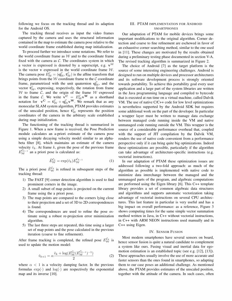
where N is the number of frames and Mi is the number ofmap points found in frame i. Figure 6 shows the values of thismetric for the first 120 frames of two of our test sequences.For every sequence the tracking algorithm has been repeatedvarying two parameters: number of map points searched andframe rate ratio ρ. This last parameter is used to simulatethe effects of long elaboration times, and is defined as: ρ =rcam/rtrack, where rcam is the frame rate of the video sourceand rtrack is the frame tracking rate of our software. A valueof ρ = 1 corresponds to tracking at full frame rate, ρ = 2means tracking every second frame and so on.
A first noteworthy observation regards the effects of chang-ing the number of features: it can be seen that increasing thisnumber doesn’t always mean better accuracy. An explanationof this behavior can be found in the fact that the map pointsto be searched in every frame are selected giving priority tothe most recognizable ones, so increasing the number of map
100 150 200 250 300 350 400 450 5001,6000
1,7000
1,8000
1,9000
2,0000
2,1000
number of featuresre
proj
ectio
ner
rorR
MS
(px)
100 150 200 250 300 350 400 450 5001,6200
1,6400
1,6600
1,6800
1,7000
number of features
repr
ojec
tion
erro
rRM
S(p
x)
Fig. 6. Reprojection error RMS for two sequences. From blue to brown: ρ = 1, 2, 3, 4, 5
38 39 40 410.89
0.9
0.91
0.92
0.93
0.94
0.95
time (s)
q x
38 39 40 41−0.25
−0.2
−0.15
−0.1
−0.05
0
0.05
0.1
0.15
0.2
time (s)
q y
38 39 40 41−0.2
−0.15
−0.1
−0.05
0
0.05
0.1
0.15
time (s)
q z
38 39 40 41
0.3
0.32
0.34
0.36
0.38
0.4
0.42
time (s)
q w
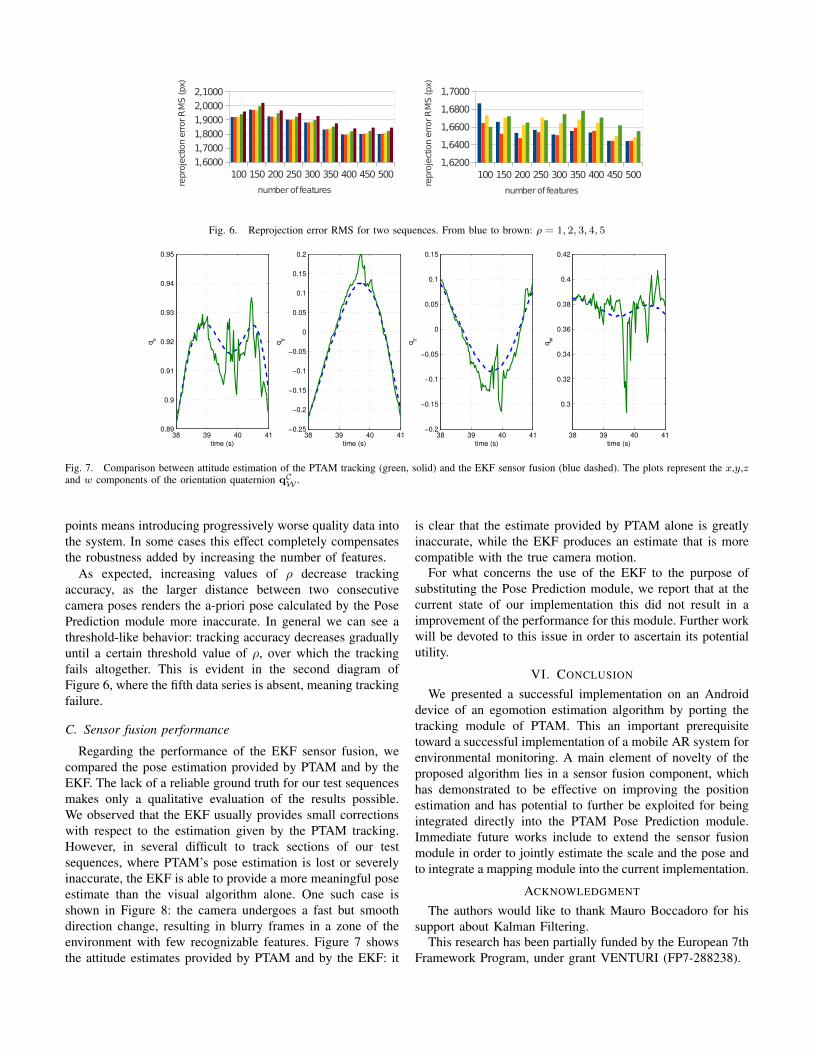
Fig. 7. Comparison between attitude estimation of the PTAM tracking (green, solid) and the EKF sensor fusion (blue dashed). The plots represent the x,y,zand w components of the orientation quaternion qC
W .
points means introducing progressively worse quality data intothe system. In some cases this effect completely compensatesthe robustness added by increasing the number of features.
As expected, increasing values of ρ decrease trackingaccuracy, as the larger distance between two consecutivecamera poses renders the a-priori pose calculated by the PosePrediction module more inaccurate. In general we can see athreshold-like behavior: tracking accuracy decreases graduallyuntil a certain threshold value of ρ, over which the trackingfails altogether. This is evident in the second diagram ofFigure 6, where the fifth data series is absent, meaning trackingfailure.
C. Sensor fusion performance
Regarding the performance of the EKF sensor fusion, wecompared the pose estimation provided by PTAM and by theEKF. The lack of a reliable ground truth for our test sequencesmakes only a qualitative evaluation of the results possible.We observed that the EKF usually provides small correctionswith respect to the estimation given by the PTAM tracking.However, in several difficult to track sections of our testsequences, where PTAM’s pose estimation is lost or severelyinaccurate, the EKF is able to provide a more meaningful poseestimate than the visual algorithm alone. One such case isshown in Figure 8: the camera undergoes a fast but smoothdirection change, resulting in blurry frames in a zone of theenvironment with few recognizable features. Figure 7 showsthe attitude estimates provided by PTAM and by the EKF: it
is clear that the estimate provided by PTAM alone is greatlyinaccurate, while the EKF produces an estimate that is morecompatible with the true camera motion.
For what concerns the use of the EKF to the purpose ofsubstituting the Pose Prediction module, we report that at thecurrent state of our implementation this did not result in aimprovement of the performance for this module. Further workwill be devoted to this issue in order to ascertain its potentialutility.
VI. CONCLUSION
We presented a successful implementation on an Androiddevice of an egomotion estimation algorithm by porting thetracking module of PTAM. This an important prerequisitetoward a successful implementation of a mobile AR system forenvironmental monitoring. A main element of novelty of theproposed algorithm lies in a sensor fusion component, whichhas demonstrated to be effective on improving the positionestimation and has potential to further be exploited for beingintegrated directly into the PTAM Pose Prediction module.Immediate future works include to extend the sensor fusionmodule in order to jointly estimate the scale and the pose andto integrate a mapping module into the current implementation.
ACKNOWLEDGMENT
The authors would like to thank Mauro Boccadoro for hissupport about Kalman Filtering.
This research has been partially funded by the European 7thFramework Program, under grant VENTURI (FP7-288238).
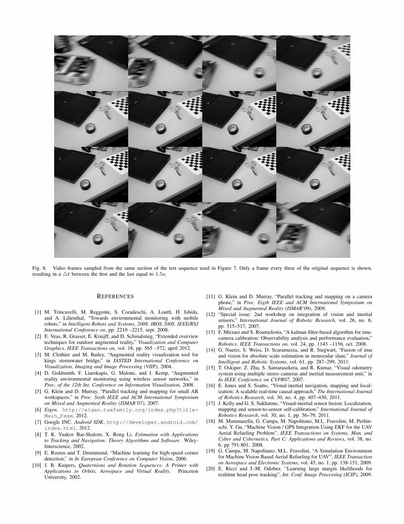
Fig. 8. Video frames sampled from the same section of the test sequence used in Figure 7. Only a frame every three of the original sequence is shown,resulting in a 4t between the first and the last equal to 1.5s.
REFERENCES
[1] M. Trincavelli, M. Reggente, S. Coradeschi, A. Loutfi, H. Ishida,and A. Lilienthal, “Towards environmental monitoring with mobilerobots,” in Intelligent Robots and Systems, 2008. IROS 2008. IEEE/RSJInternational Conference on, pp. 2210 –2215, sept. 2008.
[2] E. Veas, R. Grasset, E. Kruijff, and D. Schmalstieg, “Extended overviewtechniques for outdoor augmented reality,” Visualization and ComputerGraphics, IEEE Transactions on, vol. 18, pp. 565 –572, april 2012.
[3] M. Clothier and M. Bailey, “Augmented reality visualization tool forkings stormwater bridge,” in IASTED International Conference onVisualization, Imaging and Image Processing (VIIP), 2004.
[4] D. Goldsmith, F. Liarokapis, G. Malone, and J. Kemp, “Augmentedreality environmental monitoring using wireless sensor networks,” inProc. of the 12th Int. Conference on Information Visualisation, 2008.
[5] G. Klein and D. Murray, “Parallel tracking and mapping for small ARworkspaces,” in Proc. Sixth IEEE and ACM International Symposiumon Mixed and Augmented Reality (ISMAR’07), 2007.
[6] Eigen. http://eigen.tuxfamily.org/index.php?title=Main_Page, 2012.
[7] Google INC. Android SDK. http://developer.android.com/index.html, 2012.
[8] T. K. Yaakov Bar-Shalom, X. Rong Li, Estimation with Applicationsto Tracking and Navigation: Theory Algorithms and Software. Wiley-Interscience, 2002.
[9] E. Rosten and T. Drummond, “Machine learning for high-speed cornerdetection,” in In European Conference on Computer Vision, 2006.
[10] J. B. Kuipers, Quaternions and Rotation Sequences: A Primer withApplications to Orbits, Aerospace and Virtual Reality. PrincetonUniversity, 2002.
[11] G. Klein and D. Murray, “Parallel tracking and mapping on a cameraphone,” in Proc. Eigth IEEE and ACM International Symposium onMixed and Augmented Reality (ISMAR’09), 2009.
[12] “Special issue: 2nd workshop on integration of vision and inertialsensors,” International Journal of Robotic Research, vol. 26, no. 6,pp. 515–517, 2007.
[13] F. Mirzaei and S. Roumeliotis, “A kalman filter-based algorithm for imu-camera calibration: Observability analysis and performance evaluation,”Robotics, IEEE Transactions on, vol. 24, pp. 1143 –1156, oct. 2008.
[14] G. Nuetzi, S. Weiss, D. Scaramuzza, and R. Siegwart, “Fusion of imuand vision for absolute scale estimation in monocular slam,” Journal ofIntelligent and Robotic Systems, vol. 61, pp. 287–299, 2011.
[15] T. Oskiper, Z. Zhu, S. Samarasekera, and R. Kumar, “Visual odometrysystem using multiple stereo cameras and inertial measurement unit,” inIn IEEE Conference on CVPR07, 2007.
[16] E. Jones and S. Soatto, “Visual-inertial navigation, mapping and local-ization: A scalable real-time causal approach,” The International Journalof Robotics Research, vol. 30, no. 4, pp. 407–430, 2011.
[17] J. Kelly and G. S. Sukhatme, “Visual-inertial sensor fusion: Localization,mapping and sensor-to-sensor self-calibration,” International Journal ofRobotics Research, vol. 30, no. 1, pp. 56–79, 2011.
[18] M. Mammarella, G. Campa, M. Napolitano, M.L. Fravolini, M. Perhin-schi, Y. Gu, “Machine Vision / GPS Integration Using EKF for the UAVAerial Refueling Problem”, IEEE Transactions on Systems, Man, andCyber and Cybernetics, Part C: Applications and Reviews, vol. 38, no.6, pp 791-801, 2008.
[19] G. Campa, M. Napolitano, M.L. Fravolini, “A Simulation Environmentfor Machine Vision Based Aerial Refueling for UAV”, IEEE Transactionon Aerospace and Electronic Systems, vol. 45, no. 1, pp. 138-151, 2009.
[20] E. Ricci and J.-M. Odobez. “Learning large margin likelihoods forrealtime head pose tracking”, Int. Conf. Image Processing (ICIP), 2009.