an optical-inertial tracking system for fully …...an optical-inertial tracking system for...
TRANSCRIPT

An Optical-Inertial Tracking System for Fully-enclosed VR Displays
A. Hogue, M. R. Jenkin, R. S. Allison
{hogue,jenkin,allison}@cs.yorku.ca
Centre for Vision Research and Department of Computer Science
York University, Toronto, Ontario, Canada.
Abstract
This paper describes a hybrid optical-inertial tracking
technology for fully-immersive projective displays. In or-
der to track the operator, the operatorwears a 3DOFcom-
mercial inertial tracking systemcoupledwith a set of laser
diodes arranged in a known configuration. The projec-
tion of this laser constellation on the display walls are
tracked visually to compute the 6DOF absolute head pose
of the user. The absolute pose is combined with the iner-
tial tracker data using an extendedKalman filter tomain-
tain a robust estimate of position and orientation. This
paper describes the basic tracking system including the
hardware and software infrastructure.
1. Introduction
For a virtual reality system to provide a realis-tic visual display to the user, it is often necessary toknow the location and orientation of the user’s headin order to project the correct images on all sides ofthe display. If this is not done correctly, the user ismore likely to experience discomfort (headaches, nau-sea, disorientation; symptoms collectively known ascybersickness[13]). In non-fully-enclosed displays, it ispossible to use commercial head tracking systems sincethe tracking equipment can be positioned in such away that it does not interfere with the user’s view ofthe scene (i.e. behind the user). Such an approach isnot possible in a fully enclosed environment. Track-ing a user within a fully-enclosed projection-based dis-play such as COSMOS[16, 3], HyPi-6[6, 10], PDC VR-CUBE[2], C6[7], ALICE[12], and IVY[11] is a morecomplex task. The user is fully-enclosed in the dis-play volume, and there is no reasonable place for vis-ible tracking equipment as it interferes with the dis-play’s immersive effect.
Given this constraint, the tracking technology ofchoice for current fully-enclosed displays is electro-
Figure 1. IVY: The Immersive Visual environ-ment at York. IVY is shown here with the rear(entry) wall removed in order to show the struc-ture of the device more clearly.
magnetic technology. However, electromagnetic track-ing systems behave poorly in the presence of metal-lic objects[8, 9], accuracy and signal strength degradeswith distance from the base emitter and the user istypically tethered to the equipment. Although varioustracking technologies have been tried in fully immersiveenvironments, no completely effective tracking technol-ogy currently exists for fully-enclosed immersive envi-ronments. Although the nature of the fully-enclosed en-vironment limits the applicability of existing trackingtechnologies, the fully-enclosed nature of the hardwarecan also be exploited in order to track the user. Specif-ically, the surface that surrounds the user can be usedas a screen upon which an optical tracking system canbe deployed.
2. Hybrid Tracking Approach
In order to overcome the limitations of existing mag-netic trackers, we have developed a novel “outside in”

Camera
Fully−enclosed display (IVY)
Laser Projection
Figure 2. Optical Tracking Approach. The userwears low power laser diodes whose projectionson the screen surfaces are tracked via camerasoutside of the display. The head pose is deter-mined from these projections alone.
optical tracking system (briefly described in [11]) fortracking users within a fully enclosed projective im-mersive environment and have coupled it with a com-mercial 3DOF inertial head tracker to maintain track-ing in the presence of fast head motions. The opticaltracker utilizes commercial cameras and computers, iscapable of obtaining 6 DOF pose estimates of the userwithin the environment at 15-20Hz in its current im-plementation, and can be used as either a standalonetracking system or as part of a hybrid optical-inertialtracking system[5].
The basic idea (see Figure 2 for an illustration) is touse the projective surfaces outside of the view of theuser to track the user within the environment. A fixedarrangement of low power laser diodes is attached to ahelmet worn by the user (see Figure 3). Cameras arepositioned behind the screens such that they can viewthe entire projection surface. By tracking the projec-tions of the laser beams as they strike the projectivesurfaces, we are able to exploit the known geometry ofthe lasers, apply constraints to the pose of the device,and are thus able to compute and track the user’s cor-rect head pose. The absolute pose information obtainedby the vision system is combined with relative iner-tial data via the inertial sensor. An extended Kalmanfilter[15] is employed to predict, gate, smooth, and in-tegrate the inertial and optical pose estimates to ob-tain the final pose of the user.
Various configurations of laser diodes could be usedto localize the user. Our implementation uses a simplearrangement of four laser diodes in the geometric con-figuration shown in Figure 4. Two of the laser diodesare arranged to project in opposite directions along a
(a) (b)
Figure3.Userwithhelmet (a)andhybrid inertial-optical tracking device (b). Note that the lasersare mounted behind the user so that the laserbeams strike walls outside of the user’s view andcannot be seen.
single line, and the other two diodes are arranged sothat they project orthogonal to each other and orthog-onal to this line. The projection directions of all fourlaser diodes intersect at a single point, P0. Given theprojections of the four laser diodes on the exterior wallsof the environment it is possible to obtain strong con-straints on P0 and to define a unique 3D coordinateframe centered at this point.
To demonstrate this, we break the problem downinto two parts. The first is to determine P0 and the co-ordinate system aligned with P0 given that one canidentify the three-dimensional position at which thebeam from specific diodes strike the various walls, andthe second is to determine which laser spot on a wallcorresponds to which laser emitter.
For the remainder of this discussion, P1...P4 are the3D positions at which the laser beams from the respec-tive laser diodes strike the walls of the environment.P0 lies at the intersection of P1P2 with a perpendicu-lar line that passes through point P3. The point P0 canbe found quite easily by noting that P0 lies along theline defined by P1 + λ(P2 − P1) and P1P2 · P0P3 = 0.Solving these equations for P0 yields
P0 = P1 +(P3 − P1) · (P2 − P1)
||P2 − P1||2(P2 − P1)
This defines the origin of the frame, P0P3 defines theforward direction vector for the frame, and the nor-mal of the plane is defined by points P1, P2, P3; ~n =P0P1 ×P0P3, which determines the direction of the up

Figure 4. Basic laser geometry. The four lasersare established so that lines drawn through theirbeams would intersect at a common point P0,and P3P0 ·P1P2 = P4P0 ·P1P2 = P3P0 ·P4P0 = 0.
vector. Although P4 is not required in order to com-pute this frame (provided that the assignment of laserspots to diodes is known), P4 will prove useful by pro-viding an additional constraint in terms of determiningthe appropriate mapping from laser spots to emitters.In terms of the geometry it is important to note thatP0P4 is perpendicular to the plane defined by pointsP1P2P3.
These calculations assume that we know the cor-respondence between each laser diode and each laserprojection. In practice this may be accomplished us-ing different wavelengths, or by pulsing the lasers atknown frequencies. In our current implementation wetake a more algorithmic approach and use the geome-try to place constraints on the finite number of possi-ble emitter-laser spot labellings.
We must determine the appropriate labelings of thetracked laser projections Pi, Pj , Pk, and Pl with theactual laser points P1, P2, P3, and P4. There are 24possible assignments of the laser points to the emitters.Of all 24 possible assignments, only four are consistentwith the geometry of the emitters[5]. Figure 6 showsexamples of the possible labelings and the impact thishas on the pose computation.
Although there are four configurations that are con-sistent with the geometry of the laser diodes, thethree incorrect assignments are sufficiently distantfrom the correct pose to be easily disambiguated us-ing temporal coherence. If the correct assignment is(Pi, Pj , Pk, Pl) → (P1, P2, P3, P4), then the three in-correct assignments are
1. (Pi, Pj , Pk, Pl) → (P2, P1, P4, P3). This configura-tion has the same P0 as the correct configuration,but is rotated by 180 degrees. With a 15Hz sam-pling rate, the user would have to rotate at roughly1350 deg/sec before this configuration can be con-fused with the correct one.
(a) (b)
Figure 5. (a) The original inertial device com-posed of six accelerometers (b)The Inertiacube2
from Intersense r©
2. (Pi, Pj , Pk, Pl) → (P3, P4, P2, P1). This incorrectassignment and the final remaining assignmenthave a different P0, and an orientation changeof at least 90 degrees. This configuration, likethe following configuration, is extremely unsta-ble and can only occur under extremely unusualconditions[5]. With a 15Hz sampling rate, the userwould have to rotate at roughly 675 deg/sec be-fore this configuration can be confused with thecorrect one.
3. (Pi, Pj , Pk, Pl) → (P4, P3, P1, P2). This incorrectassignment is similar to the one above. It has adifferent P0 as well as at least a 90 degree orienta-tion change.
A simple temporal tracking system coupled withgating is used to discard these incorrect assignments.Although these constraints allow us to keep a consis-tent pose, there is still an issue of estimating the initialpose. In our current implementation, the initial correctassignment is chosen manually. Limiting the tracked ro-tation to less than 500 deg/sec eliminates the three in-correct assignments. Inertial data can also be used toaid in disambiguation.
3. Implementation Details
We previously experimented with a 6DOF inertialsystem[5] (See Figure 5) comprised of six linear ac-celerometers and used differential measurements fromthe accelerometers to estimate the angular accelera-tions. Unfortunately due to calibration issues the poseestimates were valid only for a fraction of a second

before large errors were accumulated. We then optedto purchase a commercially available 3DOF orienta-tion tracker from Intersense r©. The InertiaCube2 hasa raw data update rate of 180Hz, 0.01o angular resolu-tion and 1o RMS angular accuracy. This has resulted ina considerable improvement in terms of performance ofthe inertial system. The optical system is comprised ofeight digital FirewireTM cameras (capturing 640x480resolution grayscale images) situated outside the im-mersive display aimed at each of the rear-projectionscreens which allow us to track the multiple laser pro-jections. Each camera is equipped with an optical wave-length bandpass filter with a peak response at 650nm(the laser diode wavelength). This allows us to sim-plify the image processing routine speeding up the re-sponse of the tracking system as a whole. To find thecentroid of the laser dot in each image, we employ asub-pixel peak detector[1].
Calibration of the optical system is performed of-fline. The transformation between the screen surfaceand each camera is modeled as a 2D planar homogra-phy and is computed using the Discrete Linear Trans-form algorithm described by Hartley and Zisserman[4].The final calibration step is to determine the relation-ship between each of the screen surfaces to the worldcoordinate system. This is accomplished by definingthe world coordinate system as the center of the dis-play and physically measuring the rigid-body transfor-mation separately for each screen.
3.1. Discarding Invalid Configurations
Once the tracked 2D laser points are available, itis possible to determine the pose of the object beingtracked. This is done using the above computation foreach possible labeling of the four laser dots (24 pos-sibilities). In order to determine which is the correctlabeling, we impose geometric constraints on the solu-tion and compute an error function, ε(i), that allowsus to determine which labeling is the correct one. Us-ing three constraints, we are able to determine the cor-rect solution (up to a reflection, see Figure 6(b)) thatcorresponds properly to the pose of the device. Define
ε(i) = αε⊥(i) + βD(i) + γF(i) (1)
where i is the current permutation of laser points, α, β,and γ are weightings denoting the importance of eacherror function (in the results reported here, for simplic-ity α = β = γ = 1), ε⊥(i) (the perpendicular error) isthe sum of the dot products of vectors that should beperpendicular in this configuration (we take the abso-lute value of each dot product to ensure an increasingfunction), and D(i) is the distance between the com-
puted position P i0
and P i′
0where P i′
0is computed us-
ing P i4P i
2P i
1rather than P i
3P i
2P i
1. This eliminates many
of the incorrect labelings since P i0
and P i′
0will not co-
incide if the plane normal is computed with the incor-rect points. F(i) is a binary function that is 1 onlywhen our computed plane normal is in the same direc-tion as P i
4. The perpendicular error, ε⊥(i) is defined
as
ε⊥(i) =|(P i0P i
4· P i
0P i
1)| + |(P i
0P i
4· P i
0P i
2)|+
|(P i0P i
4· P i
0P i
3)| + |(P i
0P i
1· P i
0P i
3)|+
|(P i0P i
2· P i
0P i
3)|
(2)
D(i) is defined as
D(i) = ||P i0− P i′
0||2 (3)
and
F(i) =
[
1 ~n · (P i4− P i
0) >= 0
0 otherwise
]
(4)
After evaluating ε(i) for each possible labeling, theresults are sorted in ascending order according to thiserror function and the first 2 solutions are taken asthe correct pose and reflection. Although there ex-ist four possible solutions, two of these do not occurin practice as they correspond to extreme head posi-tions/orientations within the environment, and are ex-tremely unstable. It is still necessary to distinguish be-tween the final two solutions.
This is accomplished by applying a temporal co-herence property on possible body rotational velocity.Given the correct quaternion at the previous time step,qt−1, and the two possible orientations q1, q2, the errorquaternions can be computed by
qε1 = qt−1q−1
1(5)
qε2 = qt−1q−1
2(6)
and the correct orientation is determined as the errorquaternion with the smallest associated rotation angle,i.e. take the orientation with the smallest cos−1(qεi[0]).
4. Results
Figure 7 shows basic tracking within IVY. Here, thetracker was moved by hand in the horizontal planealong various simple trajectories. Although these re-sults demonstrate that the system can track a movingtarget within IVY, they do not speak to the accuracyof the tracking system. Tracking accuracy for orienta-tion and position is addressed in the following sections.
4.1. Orientation
The laser diode housing was placed on a rotationalstage in the center of IVY roughly 4’ above the floor

(a) (b) (c)
(d) (e) (f)
Figure6.Sixexamplesof the24possible labelingsandtheirassociatedcomputedpose.Shownherearescreen-shots from a simulator designed to test the configuration constraints on the laser geometry. The surroundingcube is an analogue of IVY while the smaller dots on the sides of the cube are the associated laser projec-tions. The thick line (shown in yellow) is the computed Up vector, and the computed position is the large dot(showninred).Theconnecting linesbetweenlaserpoints indicatewhich laserswereusedtocomputetheplanefororientation.Each image is labeledwith the text“CORRECTPOSE”or“INCORRECTPOSE”which is au-tomaticallycomputedusingonlystaticconstraints.(a) isthecorrectlycomputedposewhile(b) is incorrectbutcannotbedistinguishedusingonlystaticconstraints.Notethat(b)isactuallythecorrectposerotatedby180de-greesaroundanobliqueaxis.Asimpletemporalmechanismisusedtodistinguishbetweenthesetwosolutions.
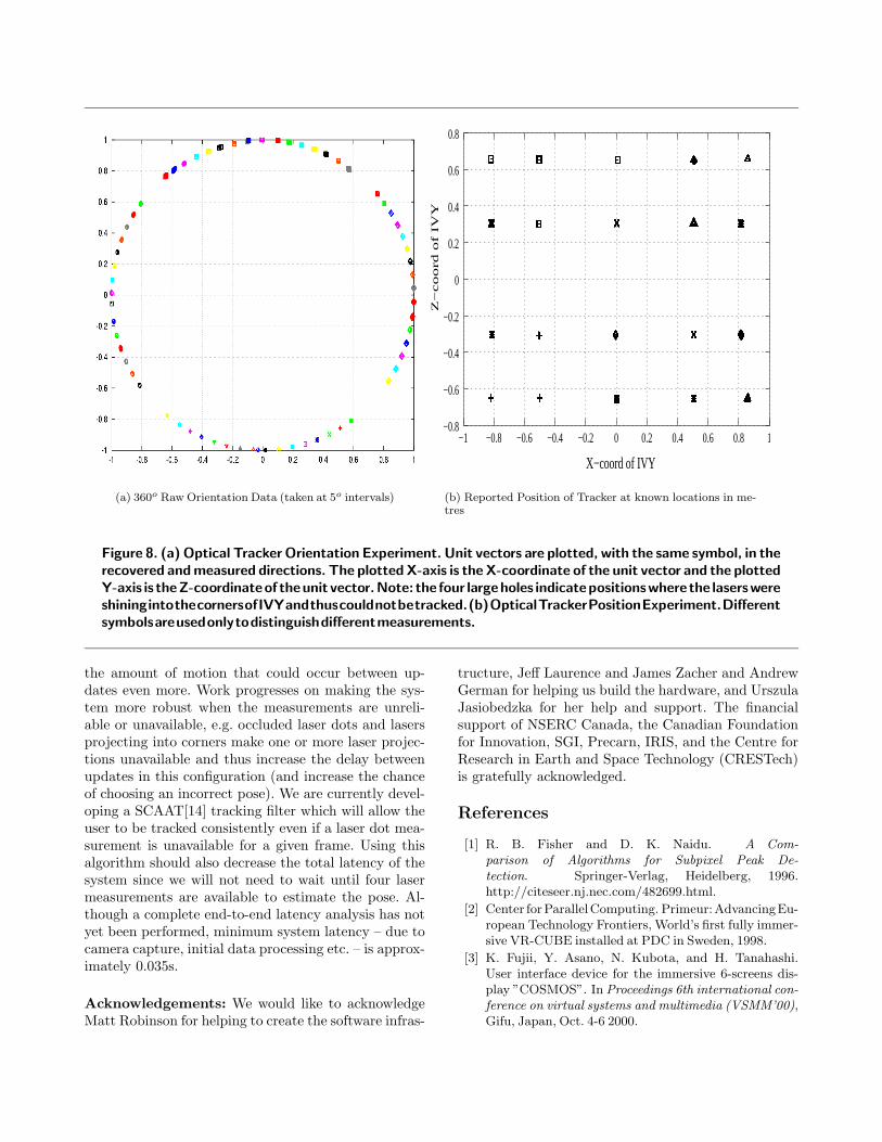
that allowed us to rotate the device precisely at 1o in-tervals. Figure 8(a) shows the raw data points for a full360o rotation on the azimuth at 5o intervals. For eachdirection vector, points on the unit circle are drawn atboth the measured and correct orientation in the samecolour (note that due to the accuracy of the measure-ment these points appear almost coincident). A funda-mental limitation of this tracking system within a cube-shaped immersive display can be seen when the lasersshine into the corners. At this time no data can be col-lected since the laser projections cannot be seen, andtracking is lost until the lasers shine onto the screen.Note that these gaps can be filled in by using the sec-ondary inertial system. In a second orientation exper-iment, rotational data were collected over a 10 degreerange at 1 degree intervals on the azimuth. The rela-
tive angle, shown in Table 1, was computed betweenthe direction vectors X-Z components and the first re-ported direction vector. The mean error of this exer-cise was approximately 0.1o while the max error wasapproximately 0.3o.
4.2. Position
Several experiments were performed to evaluate theposition reported from the tracking system. To esti-mate the accuracy of the position estimates, we placedthe device at 20 known locations within IVY andrecorded the tracker output. The raw data in this testis illustrated in Figure 8(b). The mean absolute posi-tion error was modest at 1.13cm but there were sev-eral cases where the error was nearly 5cm. We believe

(a) Rectangular Trajectory (b) Elliptical Trajectory (c) Triangular Trajectory
Figure 7.BasicTrackingResults.Theabovegraphswere createdbymoving the tracker byhandwith differenttrajectoriesontheXZplane.
Rotational Stage Computed Angle0o 0.0000o
1o 0.9229o
2o 1.9101o
3o 3.2703o
4o 4.1654o
5o 5.0992o
6o 6.2851o
7o 7.0167o
8o 8.3210o
9o 9.1814o
10o 9.8664o
Table 1. Computed angles between the reporteddirectionvectorsat1o increments.
the maximum error in the system is due to the off-axisplacement of one of the ceiling cameras which as a re-sult has a large perspective distortion and much lowerscreen resolution along one side of the immersive dis-play.
The noise covariance of each position estimate wasalso computed using a Linear Kalman filter with vari-ance of 1cm2 on position (A typical example can beseen in Figure 9(a)). The small covariance (approxi-mately 0.5cm) in the position is attributable to thenoise in each laser position estimate due to the lim-ited resolution of the cameras. Since we are acquiring640x480 resolution images from the cameras, the 2.29mscreen is imaged at approximately 500 pixels, making 1camera pixel correspond to approximately 0.5cm on thescreen surface. Using higher resolution images wouldincrease the precision of the tracking system since itwould allow us to make better estimates of the laser po-
sitions. Since the walls of the display are fabric walls,the screens vibrate and move slightly when in the pres-ence of large motion. Concerned as to how this wouldaffect the position estimate, we placed the device in astationary position and recorded data while violentlymoving the screen fabric on all walls. The covarianceof the estimate can be seen in Figure 9(b). The sys-tem reacts well with a spread of approximately 1.5cmeven in the presence of large motion of the screen sur-faces.
5. Summary and future work
The optical tracking approach for fully immersiveenvironments presented here has many advantages overexisting approaches. The accuracy achieved is not afunction of the distance of the user from a base station.The system performance is not degraded by metal-lic objects or other interference. The user is unteth-ered, which is inherent to the laser system since it isfully self contained and the inertial system is unteth-ered from a base computer due to the use of a hand-held PDA and a wireless link to obtain the inertial es-timates. Also, the user is not required to wear a largeencumbering device which could compromise their im-mersive experience. Using off-the-shelf FireWire r© dig-ital video cameras allows the tracking system to evolvewith the commercial market making it possible to in-crease the resolution and framerate as new cameratechnology becomes available. Our current implemen-tation of the optical system is limited to approximately15Hz due to computing power and camera limitationswhile work continues on increasing this to 30Hz. In-creasing the framerate would have a postive impact onthe system performance. It would be easier to disam-biguate the invalid pose estimates since it would limit
(a) 360o Raw Orientation Data (taken at 5o intervals)
Z−
co
ord
of
IVY
X−coord of IVY
−0.8
−0.6
−0.4
−0.2
0
0.2
0.4
0.6
0.8
−1 −0.8 −0.6 −0.4 −0.2 0 0.2 0.4 0.6 0.8 1
(b) Reported Position of Tracker at known locations in me-tres
Figure 8. (a) Optical Tracker Orientation Experiment. Unit vectors are plotted, with the same symbol, in therecovered and measured directions. The plotted X-axis is the X-coordinate of the unit vector and the plottedY-axis is theZ-coordinateof theunit vector.Note: the four largeholes indicatepositionswhere the laserswereshiningintothecornersofIVYandthuscouldnotbetracked.(b)OpticalTrackerPositionExperiment.Differentsymbolsareusedonlytodistinguishdifferentmeasurements.
the amount of motion that could occur between up-dates even more. Work progresses on making the sys-tem more robust when the measurements are unreli-able or unavailable, e.g. occluded laser dots and lasersprojecting into corners make one or more laser projec-tions unavailable and thus increase the delay betweenupdates in this configuration (and increase the chanceof choosing an incorrect pose). We are currently devel-oping a SCAAT[14] tracking filter which will allow theuser to be tracked consistently even if a laser dot mea-surement is unavailable for a given frame. Using thisalgorithm should also decrease the total latency of thesystem since we will not need to wait until four lasermeasurements are available to estimate the pose. Al-though a complete end-to-end latency analysis has notyet been performed, minimum system latency – due tocamera capture, initial data processing etc. – is approx-imately 0.035s.
Acknowledgements: We would like to acknowledgeMatt Robinson for helping to create the software infras-
tructure, Jeff Laurence and James Zacher and AndrewGerman for helping us build the hardware, and UrszulaJasiobedzka for her help and support. The financialsupport of NSERC Canada, the Canadian Foundationfor Innovation, SGI, Precarn, IRIS, and the Centre forResearch in Earth and Space Technology (CRESTech)is gratefully acknowledged.
References
[1] R. B. Fisher and D. K. Naidu. A Com-parison of Algorithms for Subpixel Peak De-tection. Springer-Verlag, Heidelberg, 1996.http://citeseer.nj.nec.com/482699.html.
[2] Center forParallelComputing. Primeur:AdvancingEu-ropean Technology Frontiers, World’s first fully immer-sive VR-CUBE installed at PDC in Sweden, 1998.
[3] K. Fujii, Y. Asano, N. Kubota, and H. Tanahashi.User interface device for the immersive 6-screens dis-play ”COSMOS”. In Proceedings 6th international con-ference on virtual systems and multimedia (VSMM’00),Gifu, Japan, Oct. 4-6 2000.

−7 −6 −5 −4 −3 −2 −1
x 10−3
−0.218
−0.217
−0.216
−0.215
−0.214
−0.213
−0.212Covariance of X−Z position estimate (filtering with 1cm2 variance)
(a) Typical Noise Covariance of StationaryX-Z position in metres (filtering with 1cm2
variance). This shows a spread of 6mm on theZ-axis and 3mm on the X-axis.
−10 −5 0 5
x 10−3
−0.222
−0.22
−0.218
−0.216
−0.214
−0.212
−0.21
−0.208
Covariance of X−Z position estimate (filtering with 1cm2 variance − vibrating screens)
(b) Typical Noise Covariance of StationaryX-Z position in metres (filtering with 1cm2
variance). This shows that even in the pres-ence of large motion of the screen surfaces(screen movement due to fast motion withinIVY), the spreadof themeasurement is 1.5cmon the X-Axis and 1cm on the Z-axis.
Figure 9. Results from collected data. (a) shows the typical noise covariance of a stationary position, and (b)showshowthenoiseincreaseswhenthefabricscreensvibrateduetofastmotion.
[4] R. Hartley and A. Zissserman. Multiple View Geometry.Cambridge University Press; ISBN:0521623049, 2000.
[5] A. Hogue. MARVIN: a Mobile Automatic RealtimeVisual and INertial tracking system. Master’s thesis,York University, March 2003.
[6] Fraunhofer Institute IAO. http://vr.iao.fhg.de/6-Side-Cave/index.en.php.
[7] Virtual Reality Applications Center Iowa State Univer-sity. http://www.vrac.iastate.edu/about/labs/c6.
[8] V. Kindratenko. A survey of electromagnetic positiontracker calibration techniques. In Virtual Reality: Re-search, Development, and Applications, 2000. vol.5,no.3, pp. 169-182.
[9] V. Kindratenko. A comparison of the accuracy of anelectromagnetic and hybrid ultrasound-inertia positiontracking system. Presence:Teloperators andVirtual En-vironments, 10(6):657–663, 2001.
[10] I.Rotzer. FraunhoferMagazine,Syntheticworldswithinsix walls 2:2001.
[11] M. Robinson, J. Laurence, J. Zacher, A. Hogue, R. Alli-son, L. R. Harris, M. Jenkin, and W. Stuerzlinger. IVY:The Immersive Visual environment at York. In 6thInternational Immersive Projection Technology Sympo-sium, March 24-25, 2002, Orlando, Fl., 2002.
[12] Beckman Institute University of Illinois, In-tegrated Systems Laboratory. A labora-tory for immersive conitive experiments.http://www.isl.uiuc.edu/Virtual%20Tour /Tour-Pages/meet alice.htm.
[13] Joseph J. Jr. La Viola. A discussion of cybersicknessin virtual environments. In SIGCHI Bulletin, January2000. vol.32 no.1, pp.47-56.
[14] G. Welch. SCAAT: Incremental Tracking with Incom-plete Information. PhD thesis, Chapel Hill, NC, 1996.
[15] G. Welch and G. Bishop. An introduction to the kalmanfilter. Technical Report TR95-041, University of NorthCarolina at Chapel Hill, 1995.
[16] T. Yamada, M. Hirose, and Y. Isda. Developmentof a complete immersive display: COSMOS. In Proc.VSMM’98, pages 522–527, 1998.