vision-based lane crossing point tracking for motorcycles
TRANSCRIPT

HAL Id: hal-02173364https://hal.archives-ouvertes.fr/hal-02173364
Submitted on 4 Jul 2019
HAL is a multi-disciplinary open accessarchive for the deposit and dissemination of sci-entific research documents, whether they are pub-lished or not. The documents may come fromteaching and research institutions in France orabroad, or from public or private research centers.
L’archive ouverte pluridisciplinaire HAL, estdestinée au dépôt et à la diffusion de documentsscientifiques de niveau recherche, publiés ou non,émanant des établissements d’enseignement et derecherche français ou étrangers, des laboratoirespublics ou privés.
Vision-Based Lane Crossing Point Tracking forMotorcycles
Pierre-Marie Damon, Majda Fouka, Hicham Hadj-Abdelkader, Hichem Arioui
To cite this version:Pierre-Marie Damon, Majda Fouka, Hicham Hadj-Abdelkader, Hichem Arioui. Vision-Based LaneCrossing Point Tracking for Motorcycles. IEEE Intelligent Transportation Systems Conference (ITSC2019), Oct 2019, Auckland, New Zealand. �hal-02173364�
Vision-Based Lane Crossing Point Tracking for Motorcycles
Pierre-Marie Damon1, Majda Fouka1, Hicham Hadj-Abdelkader1 and Hichem Arioui1
Abstract— In this paper, we investigate a vision-based ap-proach for online lane change prediction and detection dedi-cated Powered Two-Wheeled Vehicles. The approach is com-posed of two steps. First, the road geometry (clothoid model)and the motorcycle position with respect to the road markersare deduced based an inverse perspective mapping algorithm.The relative position is represented by the vehicle lateraldisplacement and heading estimated by means of an InertialMeasurement Unit and a monocular camera. The second stepconsists of predicting the Lane Crossing Point which allows topredict the distance and time before the motorcycle crosses thelane. The algorithm is achieved without the use of any steeringsensor.
To assess the effectiveness of the proposed approach, theestimation and the prediction schemes are validated on theBikeSim framework. To this end, two scenarios are discussed :1- straight road with non-zero relative heading, and 2- curvedroad and circular vehicle trajectory.
I. INTRODUCTION
The study of the road accidents shows that the human fac-tors (57%) appear far before the meteorological or technicalissues [1]. The most frequent human causes: alcohol andspeed are responsible respectively of 31% and 25% of fatalaccidents. Distraction is also an important human factor in aroad accident that can be highlighted by, for example, lanecrossing or abnormal steering behavior. Hence, the predictionof the steering rider behavior is a crucial issue for AdvancedRiver Assistance Systems (ARAS) to warn dangerous drivesituations.
This work focuses on lane crossing prediction for pow-erred two-wheeled vehicles (P2WV). To the best of theauthor’s knowledge, the problem has never been addressedfor P2WV. The aim is to predict, whether a simple perceptionsystem, the spacial and temporal lane change information.Such information can be predicted uising the Time to LaneCrossing (TLC) and the Distance to Lane Crossing (DLC)which are key components to be estimated in order to predictcritical situations.
Several safety systems for lane departure are alreadyintegrated in modern cars. Departure Lane Assist (DLA)systems make the vehicles more autonomous, allowing toinspect the surrounding vehicles position and to detect thedriver hypo-vigilance. Lane detection can be done throughdifferent technologies [2]: Lane Departure Warning (LDW)system [3], Lane Keeping Assistance System (LKAS), etc.All those systems have been discussed, as well as theirinteroperability issue in [4], [5], [6], [7], [8].
1 Authors are with University of Evry Val d’Essonne- Paris Saclay, IBISC Laboratory, Evry, [email protected]
In some ways, the P2WV size can be seen as a weakness.They tend to frequently change travel direction and speed,regardless number of lanes or their width. Consequently, thelane crossing may create hazardous situations. To reducesafety risks, riders should try as much as possible to avoidthe middle and the overtaking lanes since that would exposethem to left side and right-side hazards posed by adjacentvehicles [9].
Currently, relevant works are planned to study the designof Lane Departure Warning for motorcycles from the controlpoint of view [10]. In [11], the lane-keeping controllerfor motorcycles was evaluated through computer simulationwith a rider-control model, in which the lane-followingperformance was improved by using a virtual-point regulator.In [12], the authors developed a Lane Change Decision aidsystem (LCDAS), which detects backward vehicles and mo-torcycles under weather and environmental. At the end, theyused a change using single camera, in order to inform thedriver of dangerous situations during lane change maneuvers.Futhermore, an optimal control theory to the lane keepingcontroller for motorcycles was presented in [13].
Nevertheless, there is a lack of literature review relatedto the problem of Lane Crossing Point (LCP) detection formotorcycles. Therefore, DLA systems for motorcycles needmore thorough investigations to be embedded in modern two-wheelers.
The remaining of this paper is organized as follows.Section II motivates the paper’s topics. Section III reviewsour previous work on Inverse Persepctive Mapping (IPM)techniques for motorcycles. Section IV discusses the distanceto lane crossing estimation. Whereas, sections V and VIpresent the results, conclude the paper and outline the futureworks.
II. PROBLEM STATEMENT
The detection and tracking of the LCP for motorcyclesinvolve several technical problems that must be overcome.The Whereas prediction is realized in most cases throughmonocular cameras by reconstructing the road profile as wellas the current position of the vehicle. This is also done undersome assumptions such as flat roads and perfectly parallelmarkings.
In the case of motorcycle riding, both previous assump-tions are violated because of a bike dynamics. Indeed, theP2WV can reach significant roll angles (the world recordis about 68◦) and undergo load transfers during brakingor acceleration phases (pitch angle significant). Followingthis, the images recorded by the front camera undergo note-worthy deformations and do not allow a direct use without

a projection in a more advantageous plan (bird-eye-viewfor example). The next section recalls our previous workon a vision based approach for accurate vehicle positionreconstruction.
This allows to recover crucial information such that theDLC or the TLC which are both proportional regarding thevehicle speed. The second step presents the algorithm ableof tracking the LCP.
Fig. 1: Captured camera image with reprojected road lanes,predicted trajectories and LCP
III. VISION-BASED INFORMATION
The contribution of this paper is based on theresults initially introduced in [14]. The readercould refer to the following videos https://www.youtube.com/playlist?list=PLRTI62SuvNymK2Dx-YKha-1a4Sp54IVs8 forvisual illustrations. In [14], the authors used the IPMtechnique combined with a road lanes filter allowing togenerate a bird-eye-view of the road markers (as presentedin figure 3). Then, a clothoid model of the road is usedto extract pertinent information such that the P2WVrelative lateral displacement and heading angle to the roadmarkers. They are respectively denoted ∆Yi and ∆ψi,where i ∈ {l, c, r} indicates left, center and right markers. Itallows to recover crucial information regarding the P2WVlocation on the road.
Furthermore, the clothoid model allows to predict the roadcurvature and its rate respectively named C0 and C1. Bothparametres allow to faithfully reconstruct the road trajectoryin the selected Region Of Interest (ROI). Note that, even ifthe ROI limit ahead of the P2WV is chosen about 30 meters(see [14]), each road marker trajectory can be extended sincewe know its third degree polynomial approximation.
Let us remind that each road lane is approximated in thecartesian coordinate system with the following expression fori ∈ {l, c, r}:
yi(x) ≈ ∆Yi + tan(∆ψi)x+1
2C0i
x2 +1
6C1i
x3 (1)
Whereas, in the simulations discussed in [14], the rightroad marker is defined as a static reference, we proposedto introduce a dynamic reference. Indeed, the accuracy ofthe lane i trajectory reconstruction mainly depends on two
factors: the proximity with this lane and its attribute (dashedor solid). Our strategy is to choose the reference amongthe right or left solid lanes regarding the estimated P2WVposition on the road (given by ∆Y and ∆ψ). Note that,choose the center marker is depreciated because it is oftendiscontinuous leading to less accurate approximation. Then,if the P2WV is traveling in the right (respectively left)lane, the right (respectively left) road marker is set asthe reference. Finally, since the road markers are assumedparallel and separated from each other by a distance L,the two others lanes trajectories are reconstructed from thereference road marker equation (1). At this point, we knowan estimation of the three lanes trajectories in the vehicleframe Fv whose the origin is the projection of the cameracenter on the ground.
IV. LANE CROSSING POINT TRACKING
Now, considering that the road lane trajectories are avail-able, the LCP tracking problem consists of finding theintersection point coordinates between the predicted roadlane and vehicle trajectories. For the latter, we addressed twocases. For both the vehicle speed is assumed constant andpositive. The first case considers a straight predicted vehicletrajectory which corresponds to a zero steering angle (δ = 0).Whereas for the second, δ is assumed constant and non zero.Under these last assumptions, the predicted vehicle trajectoryis a circular path with a constant radius. For what follows,we denoted DLC0 and DLCδ the predicted distances to theLCP respectively for straight and circular vehicle trajectories.Note that, the DLC is computed with respect to the verticalprojection of the camera center on the ground which is theorigin of the frame Fv .
Note that, for the case where δ 6= 0 (the rider is steering),we systematically compute two DLC which are DLC0 andDLCδ . The first considering a straight predicted trajectoryand the second based on a circular path prediction (seefigure 3). This allows to get a surface containing all the LCPbetween the actual circular path and the straight one. In otherwords, it provides indications about the LCP location in caseof the rider reduces the steering (increase of the trajectoryradius).
Moreover, for both scenarios (δ = 0 and δ 6= 0), we solvedthe DLC algorithm for each detected road lane. Hence,the final LCP is the nearest point among the solutions asillustrated in figure 1 and 3.
A. Straight predicted vehicle trajectory (δ = 0)
For straight predicted path, the computation of the DLCcan be easily achieved by solving the equations for i ∈{l, c, r}:
∆Yi + tan(∆ψi)x+1
2C0ix
2 +1
6C1ix
3 = 0 (2)
Let us remind (2) is expressed in the vehicle frame Fvwhere Xv corresponds to the vehicle longitudinal axis (referto 3). Hence, if xDLC0i
is a solution of equation (2) then, theDLC with regards to the lane i is trivial. It can be directly

deduced such that: DLC0i = xDLC0i. Let us remind, the
final DLC is computed such that DLC0 = min(DLC0k)
with k corresponding to the set of all the lane intersectionpoints. In figure 3, the magenta line clearly illustrates thesituation with k = {center, right}.
B. Circular predicted vehicle trajectory (δ 6= 0)
In this case, we need to reconstruct the forward predictedvehicle trajectory based on its current dynamic states. To doso, it requires to compute the vehicle slip angle denoted ψs.It can be expressed as a function of the the measured yawangle (ψ) and the angle of the trajectory tangential vector(ψt) as illustrated in figure 2.
!"!
#
$%&
'%& !(
('*, $*) $-
'-./0
.10
Vehicle trajectory
Tangent line
Circular trajectory center
Curve radius
…
…Fig. 2: Scheme of the vehicle circular path prediction
Now, let us consider that the yaw angle, measured bythe IMU, is included in the interval [−π, π]. To avoid anysingularity, we introduced the following relation:
ψs = Ψt(ψ,ψt)−Ψ(ψ)
= ψt + πsign(Ψ(ψ)
)Θ (ψt, ψ)−Ψ(ψ) (3)
with Θ and Ψ defined by the following functions:
Ψ(ψ) =
{ψ − sign(ψ)π/2 if |ψ| ≥ π/2ψ if |ψ| < π/2
(4)
and
Θ (ψt, ψ) =
{0 if
∣∣ψt −Ψ(ψ)∣∣ ≤ π/2
1 if∣∣ψt −Ψ(ψ)
∣∣ > π/2(5)
At this step, the aim is to express ψt as a function of theIMU measurements such that the body-fixed accelerations(axbf
, aybf , azbf ) and the orientation angles (φ, θ, ψ).Let us define Aj = [axj , ayj , azj ]T and Vj =
[vxj , vyj , vzj ]T as the acceleration and the speed vectorswith j = g for the global frame and j = bf for the body-fixed one. Let us remind the following relations between thetwo frames: {
Vg = RVbfAg = RAbf
(6)
where R = RψRθRΦ is the rotation matrix. The termsRψ , Rθ and RΦ denote the rotation matrices associatedrespectively to the yaw, pitch and roll Euler angles. Notethat Φ is the rotation angle about the axis which has beenpreviously pitched of θ. The real vehicle roll angle, denotedφ, can be computed using the algebraic expression:
φ = asin(cos(θ) sin(Φ)
)(7)
Furthermore, the acceleration vector in the global framecan be obtain with the relation: Ag = Vg . Combining thelatter and (6) leads to:
Ag = RVbf +RVbf (8)
Since we assumed the vehicle motion is uniform and circular(Φ = cst, θ = cst, Vbf = 0), equation (8) can be reducedto:
Ag = RVbf (9)
where R = RψRθRΦ is the time derivative of the rotationmatrix.
Using equations (6) and (9), we obtain the followingexpression:
RAbf = RVbf= RR−1Vg (10)
Afterwards, we get one expression of the speed vector inthe global frame:
Vg =MAbf (11)
where M = RR−1R = [mij ] with i, j ∈ {1, 2, 3}Let us remind that, by definition, the speed vector, ex-
pressed in the global frame, is tangent to the vehicle trajec-tory. Since ψt is the angle of the tangential direction to theP2WV trajectory, it comes:
ψt = atan
(vygvxg
)
= atan
(m21axbf
+m22aybf +m23azbfm11axbf
+m12aybf +m13azbf
)(12)
with:
m11 = sin(ψ) cos(θ)
m12 = cos(ψ) cos(Φ) + sin(ψ) sin(θ) sin(Φ)
m13 = − cos(ψ) sin(Φ) + sin(ψ) sin(θ) cos(Φ)
m21 = − cos(ψ) cos(θ)
m22 = sin(ψ) cos(Φ)− cos(ψ) sin(θ) sin(Φ)
m23 = − sin(ψ) sin(Φ)− cos(ψ) sin(θ) cos(Φ)
At this point, the vehicle slip angle denoted ψs can becomputed using equations (3), (4), (5), (7) and (12).
Now, let us consider the IMU measurements, Abf and ψ,are given at a fixed sample rate denoted ∆t. Then, under theprevious assumptions, at an instant t, the vehicle trajectory,defined by Xvh and Yvh, can be predicted with the algorithm1.
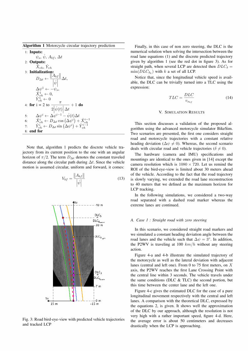
Algorithm 1 Motorcycle circular trajectory prediction
1: Inputs:ψs, ψ, Abf , ∆t
2: Outputs:Xvh, Yvh
3: Initialization:D∆t ←
∥∥Abf∥∥∣∣∣ψ∣∣∣ ∆t,
∆ψ1 ← −ψs,X1vh ← 0,
Y 1vh ← 0
4: for i = 2 toπ
2∣∣∣ψ(t)
∣∣∣∆t + 1 do
5: ∆ψi ← ∆ψi−1 − ψ(t)∆t6: Xi
vh ← D∆t cos(∆ψi
)+ Xi−1
vh
7: Y ivh ← D∆t sin(∆ψi
)+ Y i−1
vh
8: end for
Note that, algorithm 1 predicts the discrete vehicle tra-jectory from its current position to the one with an angularhorizon of π/2. The term D∆t denotes the constant traveleddistance along the circular path during ∆t. Since the vehiclemotion is assumed circular, uniform and forward, it comes:
Vbf =
∥∥Abf∥∥∣∣∣ψ∣∣∣ (13)
Fig. 3: Road bird-eye-view with predicted vehicle trajectoriesand tracked LCP
Finally, in this case of non zero steering, the DLC is thenumerical solution when solving the intersection between theroad lane equations (1) and the discrete predicted trajectorygiven by algorithm 1 (see the red dot in figure 3). As forstraight path, when several LCP are detected then DLCδ =min(DLCδk) with k a set of all LCP.
Notice that, since the longitudinal vehicle speed is avail-able, the DLC can be trivially turned into a TLC using theexpression:
TLC =DLC
vxbf
(14)
V. SIMULATION RESULTS
This section discusses a validation of the proposed al-gorithm using the advanced motorcycle simulator BikeSim.Two scenarios are presented, the first one considers straightroad and motorcycle trajectories with a constant relativeheading deviation (∆ψ 6= 0). Whereas, the second scenariodeals with circular road and vehicle trajectories (δ 6= 0).
The hardware (camera and IMU) specifications andmountings are identical to the ones given in [14] except thecamera resolution which is 1080 × 720. Let us remind theROI of the bird-eye-view is limited about 30 meters aheadof the vehicle. According to the fact that the road trajectoryis slowly varying, we extended the road lane reconstructionto 40 meters that we defined as the maximum horizon forLCP tracking.
In the following simulations, we considered a two-wayroad separated with a dashed road marker whereas theextreme lanes are continued.
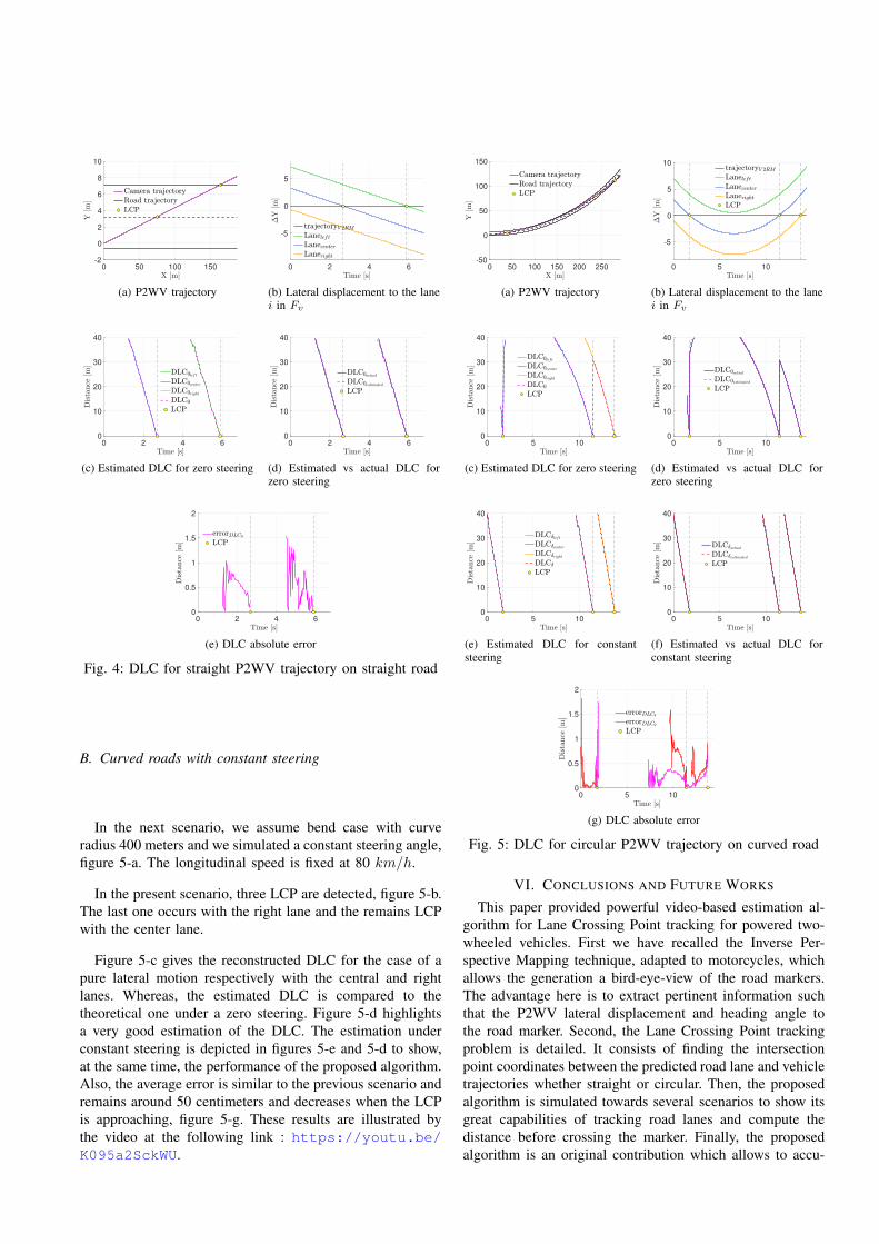
A. Case 1 : Straight road with zero steering
In this scenario, we considered straight road markers andwe simulated a constant heading deviation angle between theroad lanes and the vehicle such that ∆ψ = 3◦. In addition,the P2WV is traveling at 100 km/h without any steeringaction.
Figure 4-a and 4-b illustrate the simulated trajectory ofthe motorcycle as well as the lateral deviation with adjacentlanes (central and left one). From 0 to 75 first meters, on Xaxis, the P2WV reaches the first Lane Crossing Point withthe central line within 3 seconds. The vehicle travels underthe same conditions (DLC & TLC) the second portion, butthis time between the center lane and the left one.
Figure 4-c gives the estimated DLC for the case of a purelongitudinal movement respectively with the central and leftlanes. A comparison with the theoretical DLC, expressed bythe equations 2, is given. It shows well the approximationof the DLC by our approach, although the resolution is notvery high with a rather important speed, figure 4-d. Here,the average error is about 50 centimeters and decreasesdrastically when the LCP is approaching.
0 50 100 150-2
0
2
4
6
8
10
(a) P2WV trajectory
0 2 4 6
-5
0
5
(b) Lateral displacement to the lanei in Fv
0 2 4 60
10
20
30
40
(c) Estimated DLC for zero steering
0 2 4 60
10
20
30
40
(d) Estimated vs actual DLC forzero steering
0 2 4 60
0.5
1
1.5
2
(e) DLC absolute error
Fig. 4: DLC for straight P2WV trajectory on straight road
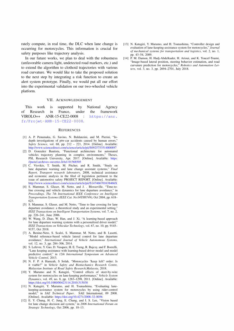
B. Curved roads with constant steering
In the next scenario, we assume bend case with curveradius 400 meters and we simulated a constant steering angle,figure 5-a. The longitudinal speed is fixed at 80 km/h.
In the present scenario, three LCP are detected, figure 5-b.The last one occurs with the right lane and the remains LCPwith the center lane.
Figure 5-c gives the reconstructed DLC for the case of apure lateral motion respectively with the central and rightlanes. Whereas, the estimated DLC is compared to thetheoretical one under a zero steering. Figure 5-d highlightsa very good estimation of the DLC. The estimation underconstant steering is depicted in figures 5-e and 5-d to show,at the same time, the performance of the proposed algorithm.Also, the average error is similar to the previous scenario andremains around 50 centimeters and decreases when the LCPis approaching, figure 5-g. These results are illustrated bythe video at the following link : https://youtu.be/K095a2SckWU.
0 50 100 150 200 250-50
0
50
100
150
(a) P2WV trajectory
0 5 10
-5
0
5
10
(b) Lateral displacement to the lanei in Fv
0 5 100
10
20
30
40
(c) Estimated DLC for zero steering
0 5 100
10
20
30
40
(d) Estimated vs actual DLC forzero steering
0 5 100
10
20
30
40
(e) Estimated DLC for constantsteering
0 5 100
10
20
30
40
(f) Estimated vs actual DLC forconstant steering
0 5 100
0.5
1
1.5
2
(g) DLC absolute error
Fig. 5: DLC for circular P2WV trajectory on curved road
VI. CONCLUSIONS AND FUTURE WORKS
This paper provided powerful video-based estimation al-gorithm for Lane Crossing Point tracking for powered two-wheeled vehicles. First we have recalled the Inverse Per-spective Mapping technique, adapted to motorcycles, whichallows the generation a bird-eye-view of the road markers.The advantage here is to extract pertinent information suchthat the P2WV lateral displacement and heading angle tothe road marker. Second, the Lane Crossing Point trackingproblem is detailed. It consists of finding the intersectionpoint coordinates between the predicted road lane and vehicletrajectories whether straight or circular. Then, the proposedalgorithm is simulated towards several scenarios to show itsgreat capabilities of tracking road lanes and compute thedistance before crossing the marker. Finally, the proposedalgorithm is an original contribution which allows to accu-
rately compute, in real time, the DLC when lane change isoccurring for motorcycles. This information is crucial forsafety purposes like trajectory analysis.
In our future works, we plan to deal with the robustness(unfavorable camera light, undetected road markers, etc.) andto extend the algorithm to clothoid trajectories with variousroad curvature. We would like to take the proposed solutionto the next step by integrating a risk function to create analert system prototype. Finally, we would put all our effortinto the experimental validation on our two-wheeled vehicleplatform.
VII. ACKNOWLEDGEMENT
This work is supported by National Agencyof Research in France, under the frameworkVIROLO++ ANR-15-CE22-0008 : https://anr.fr/Projet-ANR-15-CE22-0008.
REFERENCES
[1] A. P. Penumaka, G. Savino, N. Baldanzini, and M. Pierini, “In-depth investigations of ptw-car accidents caused by human errors,”Safety Science, vol. 68, pp. 212 – 221, 2014. [Online]. Available:http://www.sciencedirect.com/science/article/pii/S0925753514000897
[2] D. Gonzalez Bautista, “Functional architecture for automatedvehicles trajectory planning in complex environments,” Theses,PSL Research University, Apr. 2017. [Online]. Available: https://pastel.archives-ouvertes.fr/tel-01568505
[3] C. Visvikis, T. Smith, M. Pitcher, and R. Smith, “Study onlane departure warning and lane change assistant systems,” FinalReport, Transport research laboratory, 2008, technical assistanceand economic analysis in the filed of legislation pertinent to theissue of automotive safety PROJECT REPORT. [Online]. Available:http://www.sciencedirect.com/science/article/pii/S147466701638466X
[4] S. Mammar, S. Glaser, M. Netto, and J. . Blosseville, “Time-to-line crossing and vehicle dynamics for lane departure avoidance,” inProceedings. The 7th International IEEE Conference on IntelligentTransportation Systems (IEEE Cat. No.04TH8749), Oct 2004, pp. 618–623.
[5] S. Mammar, S. Glaser, and M. Netto, “Time to line crossing for lanedeparture avoidance: a theoretical study and an experimental setting,”IEEE Transactions on Intelligent Transportation Systems, vol. 7, no. 2,pp. 226–241, June 2006.
[6] W. Wang, D. Zhao, W. Han, and J. Xi, “A learning-based approachfor lane departure warning systems with a personalized driver model,”IEEE Transactions on Vehicular Technology, vol. 67, no. 10, pp. 9145–9157, Oct 2018.
[7] A. Benine-Neto, S. Scalzi, S. Mammar, M. Netto, and B. Lusetti,“Model reference-based vehicle lateral control for lane departureavoidance,” International Journal of Vehicle Autonomous Systems,vol. 12, no. 3, pp. 284–306, 2014.
[8] S. Lefevre, Y. Gao, D. Vasquez, H. E. Tseng, R. Bajcsy, and F. Borrelli,“Lane keeping assistance with learning-based driver model and modelpredictive control,” in 12th International Symposium on AdvancedVehicle Control, 2013.
[9] N. F. P. A Hamzah, S Solah, “Motorcycles ?keep left? order: Isit viable?” in Vehicle Safety and Biomechanics Research Centre,Malaysian Institute of Road Safety Research,Malaysia, 2018.
[10] Y. Marumo and N. Katagiri, “Control effects of steer-by-wiresystem for motorcycles on lane-keeping performance,” Vehicle SystemDynamics, vol. 49, no. 8, pp. 1283–1298, 2011. [Online]. Available:https://doi.org/10.1080/00423114.2010.515030
[11] N. Katagiri, Y. Marumo, and H. Tsunashima, “Evaluating lane-keeping-assistance system for motorcycles by using rider-controlmodel,” in SAE Technical Paper. SAE International, 09 2008.[Online]. Available: https://doi.org/10.4271/2008-32-0056
[12] E. Y. Chung, H. C. Jung, E. Chang, and I. S. Lee, “Vision basedfor lane change decision aid system,” in 2006 International Forum onStrategic Technology, Oct 2006, pp. 10–13.
[13] N. Katagiri, Y. Marumo, and H. Tsunashima, “Controller design andevaluation of lane-keeping-assistance system for motorcycles,” Journalof mechanical systems for transportation and logistics, vol. 2, no. 1,pp. 43–54, 2009.
[14] P. M. Damon, H. Hadj-Abdelkader, H. Arioui, and K. Youcef-Toumi,“Image-based lateral position, steering behavior estimation, and roadcurvature prediction for motorcycles,” Robotics and Automation Let-ters, vol. 3, no. 3, pp. 2694–2701, July 2018.