virtual reality welder training - american welding...
TRANSCRIPT
Session 5: Joining Technologies for Naval Applications
B. Virtual Reality Welder Training by Nancy C. Porter, Edison Welding Institute; J. Allan Cote, General Dynamics Electric Boat; Timothy D. Gifford, VRSim; and Wim Lam, FCS Controls
Introduction Welding is the key technology for fabrication and assembly of metal structures. In some industries, most notably automotive, welding is done primarily by robots or automated machinery. In many industries such as shipbuilding, heavy equipment production, and small parts fabrication, welding is a value added operation that is largely a manual process applied by humans. Training of new welders is a significant activity both for industry and for the vocational education community. Training is especially important for welders working on critical items such as pressure vessels, nuclear piping, and naval ships, where welds have high quality requirements and are carefully inspected. It is estimated that the combined annual welder training costs for all U.S. shipyards is in excess of $5M. As a result, there is active interest among naval shipbuilders to reduce welder training costs1. Virtual reality (VR) is currently used as a training tool in a number of different application areas including medicine, aviation, law enforcement, and the military2. For example, VR simulations with mixed reality haptic displays are routinely used for training surgeons in laparoscopic techniques and commercial pilots train almost exclusively on flight simulator platforms. Logically, VR technology training should be capable of improving the effectiveness of welder training. Toward this end, a VR welding trainer3 was developed for General Dynamics Electric Boat (GDEB) with funding provided by the U.S. Navy ManTech Program under contract to the Navy Joining Center of Excellence operated by Edison Welding Institute (EWI). This paper is a summary of the work performed to date.
Summary A prototype mixed reality system was created to allow a human to make a virtual gas metal arc fillet weld in the horizontal welding position. The system records process parameters, which are displayed after welding for critique and instruction. This represents a first of its kind welder training approach that leverages current state-of-the-art VR technology which is capable of integration into the product simulation/product-centered manufacturing approaches currently being developed and applied by GDEB. The project team is lead by EWI partnered with GDEB and VRSim. EWI is North America’s largest engineering and technology organization dedicated to welding and materials joining. EWI’s staff provides materials joining assistance, contract research, consulting services, and training to over 3,300 member company locations representing world-class leaders in aerospace, automotive, defense, energy, heavy manufacturing, medical, and the electronics industries. GDEB has established standards of excellence in the design, construction and lifecycle support of submarines for the U.S. Navy. VRSim is a leader in the design and development of interactive virtual reality simulations, content development, systems integration, design, development/implementation of virtual reality simulations, and visualization applications. The first year of project work produced an innovative VR welder training system keyed to shipbuilding that is easily adaptable to related defense manufacturing
Session 5: Joining Technologies for Naval Applications
applications. Currently in process, the second year of work is aimed at enhancing simulation fidelity.
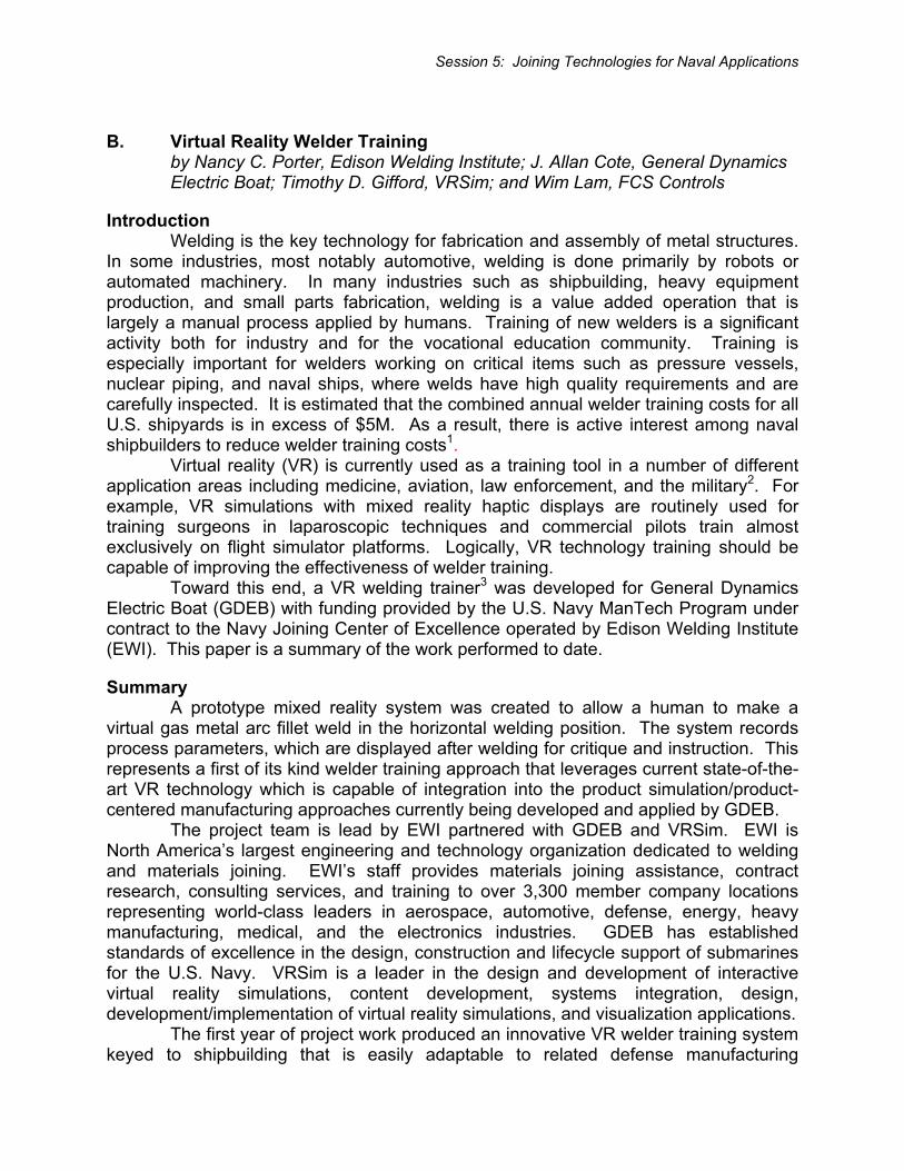
Simulation Definition The foundation of the technical approach was the identification of an appropriate welding process to simulate. Gas metal arc welding (GMAW) was selected given its widespread use in shipbuilding (and in defense manufacturing in general). Figure 1 is a schematic of GMAW showing the distinguishing characteristics of the process.
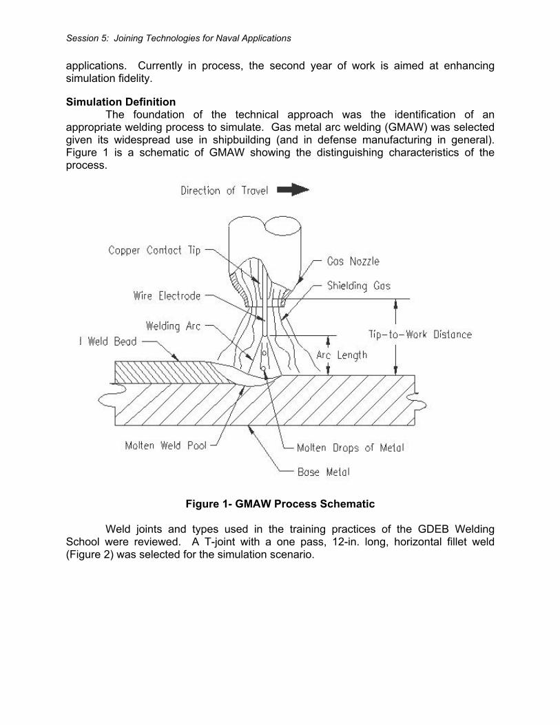
Figure 1- GMAW Process Schematic Weld joints and types used in the training practices of the GDEB Welding School were reviewed. A T-joint with a one pass, 12-in. long, horizontal fillet weld (Figure 2) was selected for the simulation scenario.
Session 5: Joining Technologies for Naval Applications
Figure 2 - Weld Joint Selected for Simulation The year one virtual reality welder training simulator required population with data that defined the weld parameters generated by the virtual user. For example, the torch angles and contact tip-to-work distance (CTWD) affect the resulting weld bead geometry (i.e., profile). Therefore, the simulator must know how variations in these parameters affect the weld bead. Relationships were empirically defined between welding parameters (inputs) and weld profile (outputs) by:
• Establishing a range of welding parameters • Generating weld samples within the parameter ranges • Generating a predictive methodology • Providing input to welding simulator on affect of welding parameters on weld
bead shape GDEB provided the following weld parameters as representative of their welding procedure specifications:
• Filler Wire: 0.045-in. diameter MIL 70S-3 (AWS ER70S-3) • Wire Feed Speed Range: 250 to 350 inches per minute (ipm) • Voltage Range: 24 to 28 • Amperage Range: 200 to 260 • Shielding Gas: 95% Argon with 5% Carbon Dioxide, flow rate set at 45 cubic feet
per hour (CFH) • Work Angle: 35 - 55 degrees • Travel Angle: 70 - 110 degrees
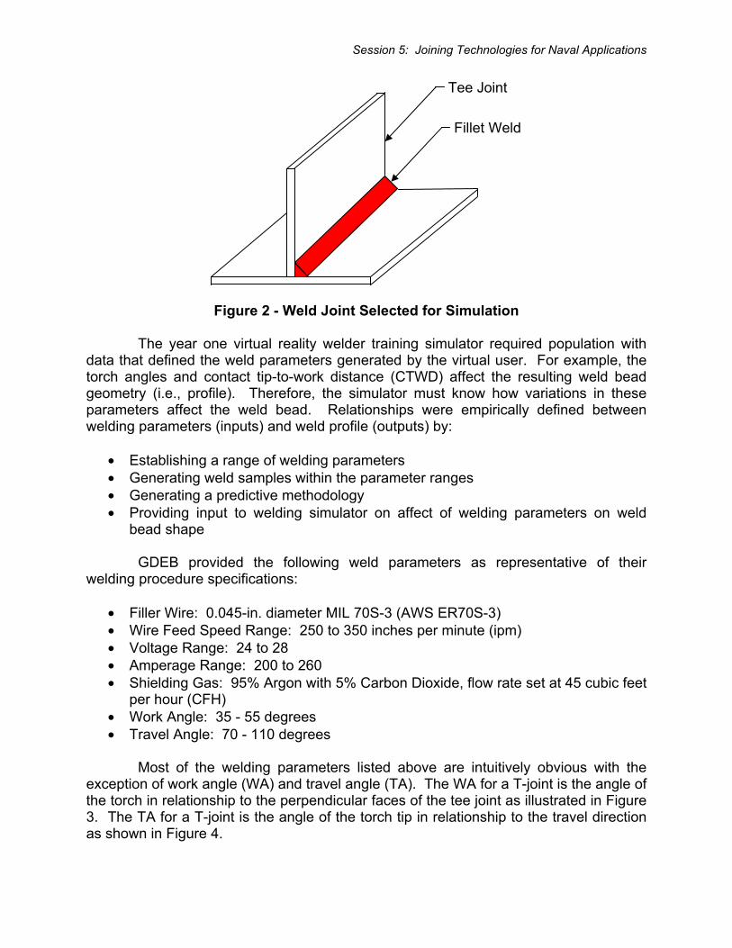
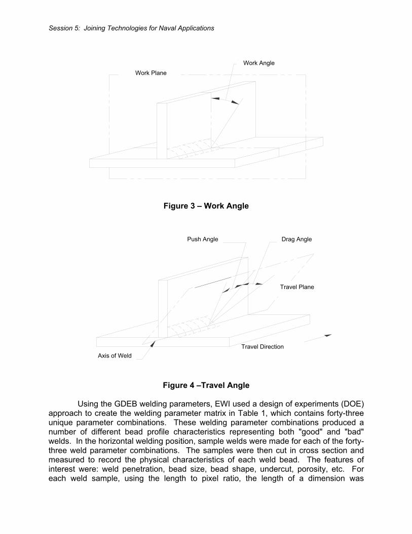
Most of the welding parameters listed above are intuitively obvious with the exception of work angle (WA) and travel angle (TA). The WA for a T-joint is the angle of the torch in relationship to the perpendicular faces of the tee joint as illustrated in Figure 3. The TA for a T-joint is the angle of the torch tip in relationship to the travel direction as shown in Figure 4.
Tee Joint
Fillet Weld
Session 5: Joining Technologies for Naval Applications
Figure 3 – Work Angle
Figure 4 –Travel Angle
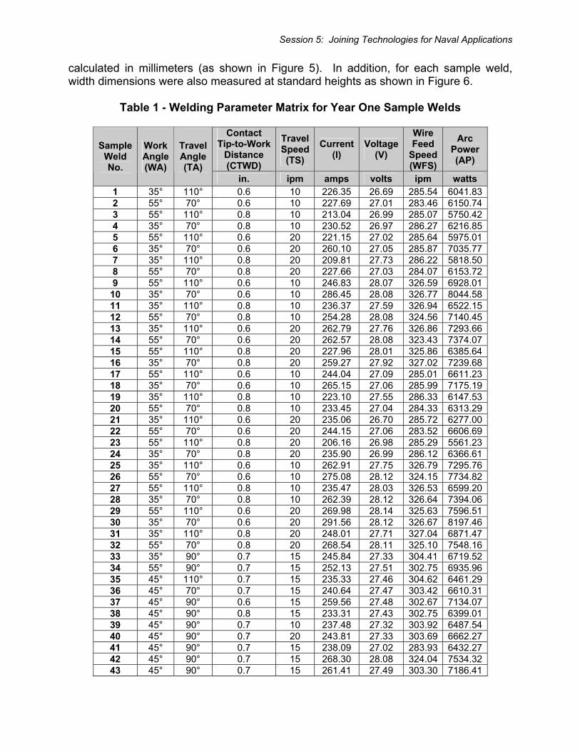
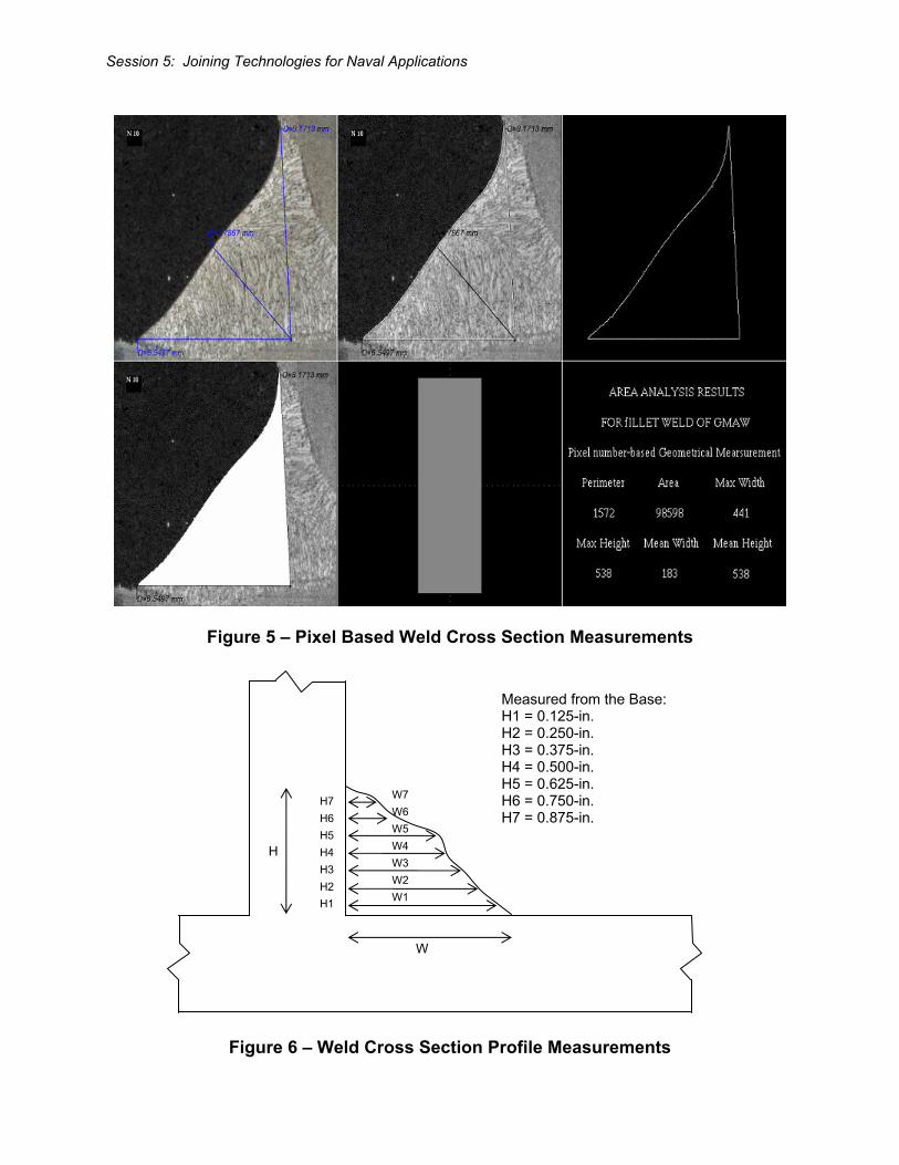
Using the GDEB welding parameters, EWI used a design of experiments (DOE) approach to create the welding parameter matrix in Table 1, which contains forty-three unique parameter combinations. These welding parameter combinations produced a number of different bead profile characteristics representing both "good" and "bad" welds. In the horizontal welding position, sample welds were made for each of the forty-three weld parameter combinations. The samples were then cut in cross section and measured to record the physical characteristics of each weld bead. The features of interest were: weld penetration, bead size, bead shape, undercut, porosity, etc. For each weld sample, using the length to pixel ratio, the length of a dimension was
Axis of Weld Travel Direction
Push Angle Drag Angle
Travel Plane
Work Angle Work Plane
Session 5: Joining Technologies for Naval Applications
calculated in millimeters (as shown in Figure 5). In addition, for each sample weld, width dimensions were also measured at standard heights as shown in Figure 6.
Table 1 - Welding Parameter Matrix for Year One Sample Welds
Contact Tip-to-Work
Distance (CTWD)
TravelSpeed(TS)
Current(I)
Voltage(V)
Wire Feed
Speed (WFS)
Arc Power (AP)
Sample Weld No.
Work Angle (WA)
Travel Angle (TA)
in. ipm amps volts ipm watts 1 35° 110° 0.6 10 226.35 26.69 285.54 6041.832 55° 70° 0.6 10 227.69 27.01 283.46 6150.743 55° 110° 0.8 10 213.04 26.99 285.07 5750.424 35° 70° 0.8 10 230.52 26.97 286.27 6216.855 55° 110° 0.6 20 221.15 27.02 285.64 5975.016 35° 70° 0.6 20 260.10 27.05 285.87 7035.777 35° 110° 0.8 20 209.81 27.73 286.22 5818.508 55° 70° 0.8 20 227.66 27.03 284.07 6153.729 55° 110° 0.6 10 246.83 28.07 326.59 6928.01
10 35° 70° 0.6 10 286.45 28.08 326.77 8044.5811 35° 110° 0.8 10 236.37 27.59 326.94 6522.1512 55° 70° 0.8 10 254.28 28.08 324.56 7140.4513 35° 110° 0.6 20 262.79 27.76 326.86 7293.6614 55° 70° 0.6 20 262.57 28.08 323.43 7374.0715 55° 110° 0.8 20 227.96 28.01 325.86 6385.6416 35° 70° 0.8 20 259.27 27.92 327.02 7239.6817 55° 110° 0.6 10 244.04 27.09 285.01 6611.2318 35° 70° 0.6 10 265.15 27.06 285.99 7175.1919 35° 110° 0.8 10 223.10 27.55 286.33 6147.5320 55° 70° 0.8 10 233.45 27.04 284.33 6313.2921 35° 110° 0.6 20 235.06 26.70 285.72 6277.0022 55° 70° 0.6 20 244.15 27.06 283.52 6606.6923 55° 110° 0.8 20 206.16 26.98 285.29 5561.2324 35° 70° 0.8 20 235.90 26.99 286.12 6366.6125 35° 110° 0.6 10 262.91 27.75 326.79 7295.7626 55° 70° 0.6 10 275.08 28.12 324.15 7734.8227 55° 110° 0.8 10 235.47 28.03 326.53 6599.2028 35° 70° 0.8 10 262.39 28.12 326.64 7394.0629 55° 110° 0.6 20 269.98 28.14 325.63 7596.5130 35° 70° 0.6 20 291.56 28.12 326.67 8197.4631 35° 110° 0.8 20 248.01 27.71 327.04 6871.4732 55° 70° 0.8 20 268.54 28.11 325.10 7548.1633 35° 90° 0.7 15 245.84 27.33 304.41 6719.5234 55° 90° 0.7 15 252.13 27.51 302.75 6935.9635 45° 110° 0.7 15 235.33 27.46 304.62 6461.2936 45° 70° 0.7 15 240.64 27.47 303.42 6610.3137 45° 90° 0.6 15 259.56 27.48 302.67 7134.0738 45° 90° 0.8 15 233.31 27.43 302.75 6399.0139 45° 90° 0.7 10 237.48 27.32 303.92 6487.5440 45° 90° 0.7 20 243.81 27.33 303.69 6662.2741 45° 90° 0.7 15 238.09 27.02 283.93 6432.2742 45° 90° 0.7 15 268.30 28.08 324.04 7534.3243 45° 90° 0.7 15 261.41 27.49 303.30 7186.41
Session 5: Joining Technologies for Naval Applications
Figure 5 – Pixel Based Weld Cross Section Measurements
Figure 6 – Weld Cross Section Profile Measurements
H
W
H7 H6 H5 H4 H3 H2 H1
W7 W6 W5 W4 W3 W2 W1
Measured from the Base: H1 = 0.125-in. H2 = 0.250-in. H3 = 0.375-in. H4 = 0.500-in. H5 = 0.625-in. H6 = 0.750-in. H7 = 0.875-in.
Session 5: Joining Technologies for Naval Applications
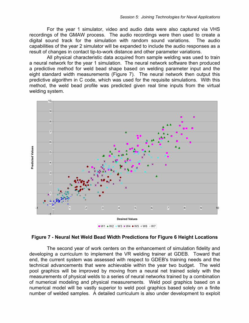
For the year 1 simulator, video and audio data were also captured via VHS recordings of the GMAW process. The audio recordings were then used to create a digital sound track for the simulation with random sound variations. The audio capabilities of the year 2 simulator will be expanded to include the audio responses as a result of changes in contact tip-to-work distance and other parameter variations. All physical characteristic data acquired from sample welding was used to train a neural network for the year 1 simulation. The neural network software then produced a predictive method for weld bead shape based on welding parameter input and the eight standard width measurements (Figure 7). The neural network then output this predictive algorithm in C code, which was used for the requisite simulations. With this method, the weld bead profile was predicted given real time inputs from the virtual welding system.
-1
0
1
2
3
4
5
6
7
8
9
10
-1 0 1 2 3 4 5 6 7 8 9 10
Desired Values
Pred
icte
d Va
lues
W1 W2 W3 W4 W5 W6 W7
Figure 7 - Neural Net Weld Bead Width Predictions for Figure 6 Height Locations The second year of work centers on the enhancement of simulation fidelity and developing a curriculum to implement the VR welding trainer at GDEB. Toward that end, the current system was assessed with respect to GDEB's training needs and the technical advancements that were achievable within the year two budget. The weld pool graphics will be improved by moving from a neural net trained solely with the measurements of physical welds to a series of neural networks trained by a combination of numerical modeling and physical measurements. Weld pool graphics based on a numerical model will be vastly superior to weld pool graphics based solely on a finite number of welded samples. A detailed curriculum is also under development to exploit
Session 5: Joining Technologies for Naval Applications
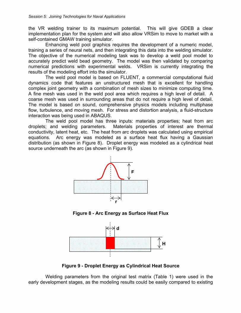
the VR welding trainer to its maximum potential. This will give GDEB a clear implementation plan for the system and will also allow VRSim to move to market with a self-contained GMAW training simulator. Enhancing weld pool graphics requires the development of a numeric model, training a series of neural nets, and then integrating this data into the welding simulator. The objective of the numerical modeling task was to develop a weld pool model to accurately predict weld bead geometry. The model was then validated by comparing numerical predictions with experimental welds. VRSim is currently integrating the results of the modeling effort into the simulator. The weld pool model is based on FLUENT, a commercial computational fluid dynamics code that features an unstructured mesh that is excellent for handling complex joint geometry with a combination of mesh sizes to minimize computing time. A fine mesh was used in the weld pool area which requires a high level of detail. A coarse mesh was used in surrounding areas that do not require a high level of detail. The model is based on sound, comprehensive physics models including multiphase flow, turbulence, and moving mesh. For stress and distortion analysis, a fluid-structure interaction was being used in ABAQUS. The weld pool model has three inputs: materials properties; heat from arc droplets; and welding parameters. Materials properties of interest are thermal conductivity, latent heat, etc. The heat from arc droplets was calculated using empirical equations. Arc energy was modeled as a surface heat flux having a Gaussian distribution (as shown in Figure 8). Droplet energy was modeled as a cylindrical heat source underneath the arc (as shown in Figure 9).
Figure 8 - Arc Energy as Surface Heat Flux
Figure 9 - Droplet Energy as Cylindrical Heat Source
Welding parameters from the original test matrix (Table 1) were used in the early development stages, as the modeling results could be easily compared to existing
F
r
d
H
Session 5: Joining Technologies for Naval Applications
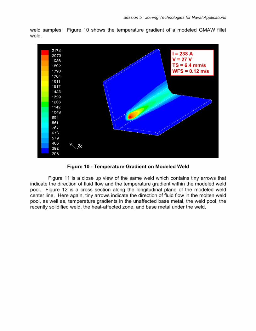
weld samples. Figure 10 shows the temperature gradient of a modeled GMAW fillet weld.
Figure 10 - Temperature Gradient on Modeled Weld
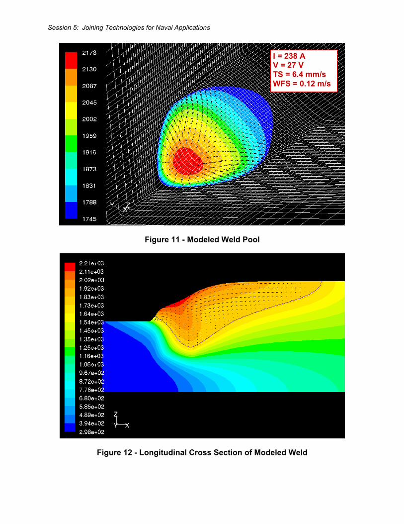
Figure 11 is a close up view of the same weld which contains tiny arrows that indicate the direction of fluid flow and the temperature gradient within the modeled weld pool. Figure 12 is a cross section along the longitudinal plane of the modeled weld center line. Here again, tiny arrows indicate the direction of fluid flow in the molten weld pool, as well as, temperature gradients in the unaffected base metal, the weld pool, the recently solidified weld, the heat-affected zone, and base metal under the weld.
I = 238 A V = 27 V TS = 6.4 mm/s WFS = 0.12 m/s
Session 5: Joining Technologies for Naval Applications
Figure 11 - Modeled Weld Pool
Figure 12 - Longitudinal Cross Section of Modeled Weld
I = 238 A V = 27 V TS = 6.4 mm/s WFS = 0.12 m/s
Session 5: Joining Technologies for Naval Applications
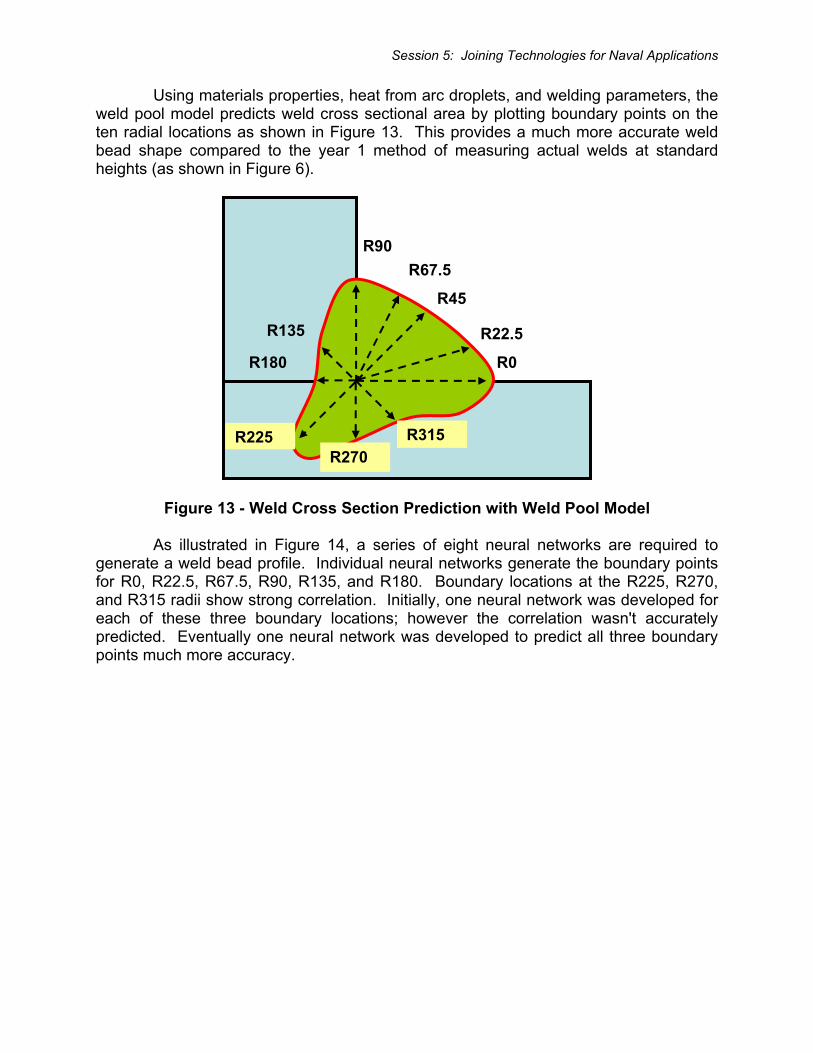
Using materials properties, heat from arc droplets, and welding parameters, the weld pool model predicts weld cross sectional area by plotting boundary points on the ten radial locations as shown in Figure 13. This provides a much more accurate weld bead shape compared to the year 1 method of measuring actual welds at standard heights (as shown in Figure 6).
Figure 13 - Weld Cross Section Prediction with Weld Pool Model
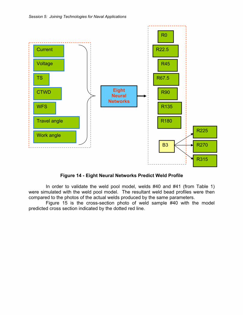
As illustrated in Figure 14, a series of eight neural networks are required to generate a weld bead profile. Individual neural networks generate the boundary points for R0, R22.5, R67.5, R90, R135, and R180. Boundary locations at the R225, R270, and R315 radii show strong correlation. Initially, one neural network was developed for each of these three boundary locations; however the correlation wasn't accurately predicted. Eventually one neural network was developed to predict all three boundary points much more accuracy.
R0
R45
R90
R135
R180
R225 R270
R315
R22.5
R67.5
Session 5: Joining Technologies for Naval Applications
Figure 14 - Eight Neural Networks Predict Weld Profile
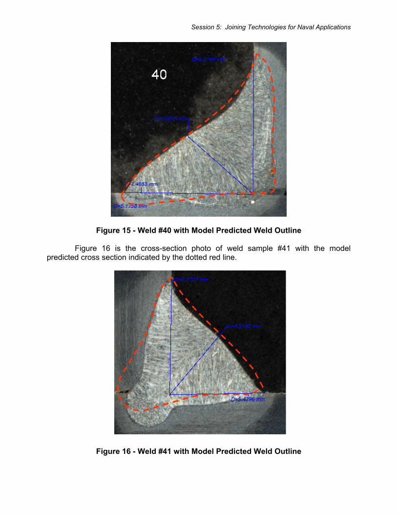
In order to validate the weld pool model, welds #40 and #41 (from Table 1) were simulated with the weld pool model. The resultant weld bead profiles were then compared to the photos of the actual welds produced by the same parameters. Figure 15 is the cross-section photo of weld sample #40 with the model predicted cross section indicated by the dotted red line.
Voltage
TS
CTWD
WFS
Travel angle
Work angle
Eight Neural
Networks
R0
Current
R45
R90
R135
R180
R225
R270
R315
R22.5
R67.5
B3
Session 5: Joining Technologies for Naval Applications
Figure 15 - Weld #40 with Model Predicted Weld Outline
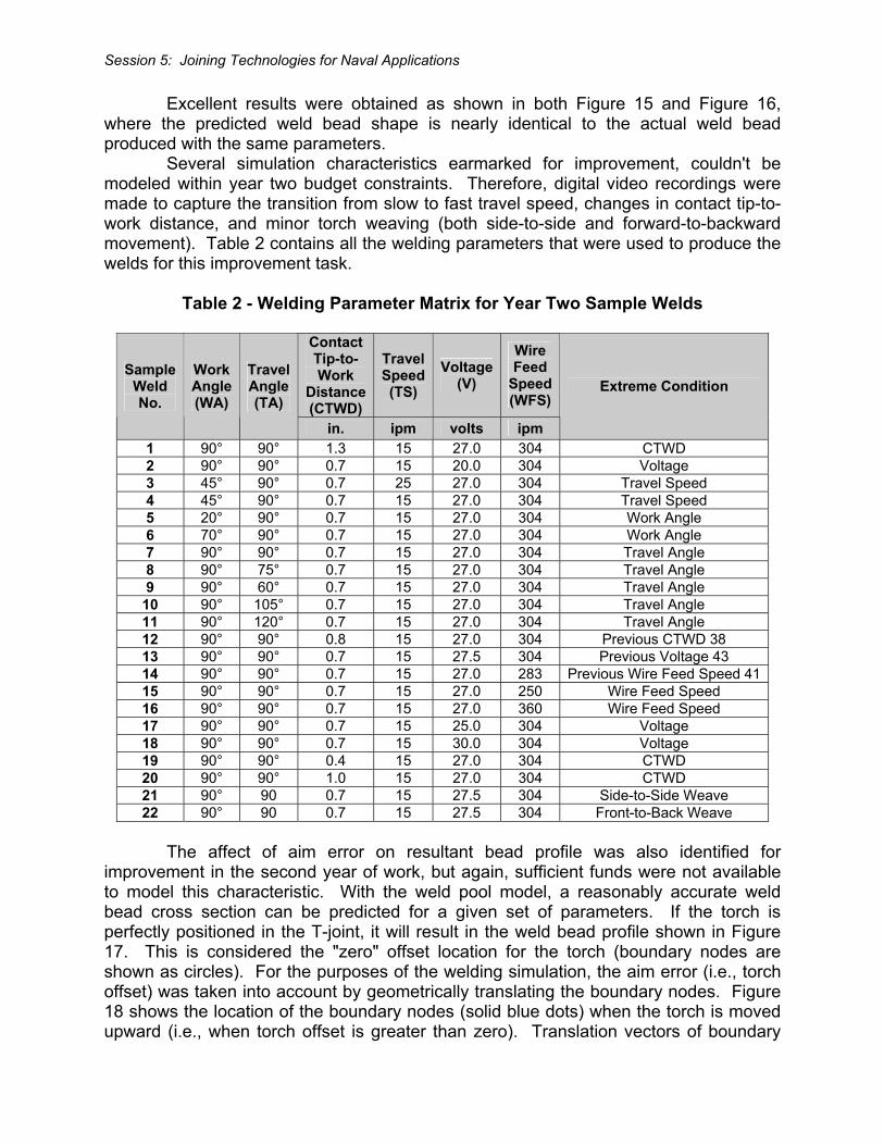
Figure 16 is the cross-section photo of weld sample #41 with the model predicted cross section indicated by the dotted red line.
Figure 16 - Weld #41 with Model Predicted Weld Outline
Session 5: Joining Technologies for Naval Applications
Excellent results were obtained as shown in both Figure 15 and Figure 16, where the predicted weld bead shape is nearly identical to the actual weld bead produced with the same parameters. Several simulation characteristics earmarked for improvement, couldn't be modeled within year two budget constraints. Therefore, digital video recordings were made to capture the transition from slow to fast travel speed, changes in contact tip-to-work distance, and minor torch weaving (both side-to-side and forward-to-backward movement). Table 2 contains all the welding parameters that were used to produce the welds for this improvement task.
Table 2 - Welding Parameter Matrix for Year Two Sample Welds
Contact Tip-to- Work
Distance(CTWD)
TravelSpeed(TS)
Voltage(V)
Wire Feed
Speed(WFS)
Sample Weld No.
Work Angle (WA)
Travel Angle (TA)
in. ipm volts ipm
Extreme Condition
1 90° 90° 1.3 15 27.0 304 CTWD 2 90° 90° 0.7 15 20.0 304 Voltage 3 45° 90° 0.7 25 27.0 304 Travel Speed 4 45° 90° 0.7 15 27.0 304 Travel Speed 5 20° 90° 0.7 15 27.0 304 Work Angle 6 70° 90° 0.7 15 27.0 304 Work Angle 7 90° 90° 0.7 15 27.0 304 Travel Angle 8 90° 75° 0.7 15 27.0 304 Travel Angle 9 90° 60° 0.7 15 27.0 304 Travel Angle
10 90° 105° 0.7 15 27.0 304 Travel Angle 11 90° 120° 0.7 15 27.0 304 Travel Angle 12 90° 90° 0.8 15 27.0 304 Previous CTWD 38 13 90° 90° 0.7 15 27.5 304 Previous Voltage 43 14 90° 90° 0.7 15 27.0 283 Previous Wire Feed Speed 4115 90° 90° 0.7 15 27.0 250 Wire Feed Speed 16 90° 90° 0.7 15 27.0 360 Wire Feed Speed 17 90° 90° 0.7 15 25.0 304 Voltage 18 90° 90° 0.7 15 30.0 304 Voltage 19 90° 90° 0.4 15 27.0 304 CTWD 20 90° 90° 1.0 15 27.0 304 CTWD 21 90° 90 0.7 15 27.5 304 Side-to-Side Weave 22 90° 90 0.7 15 27.5 304 Front-to-Back Weave
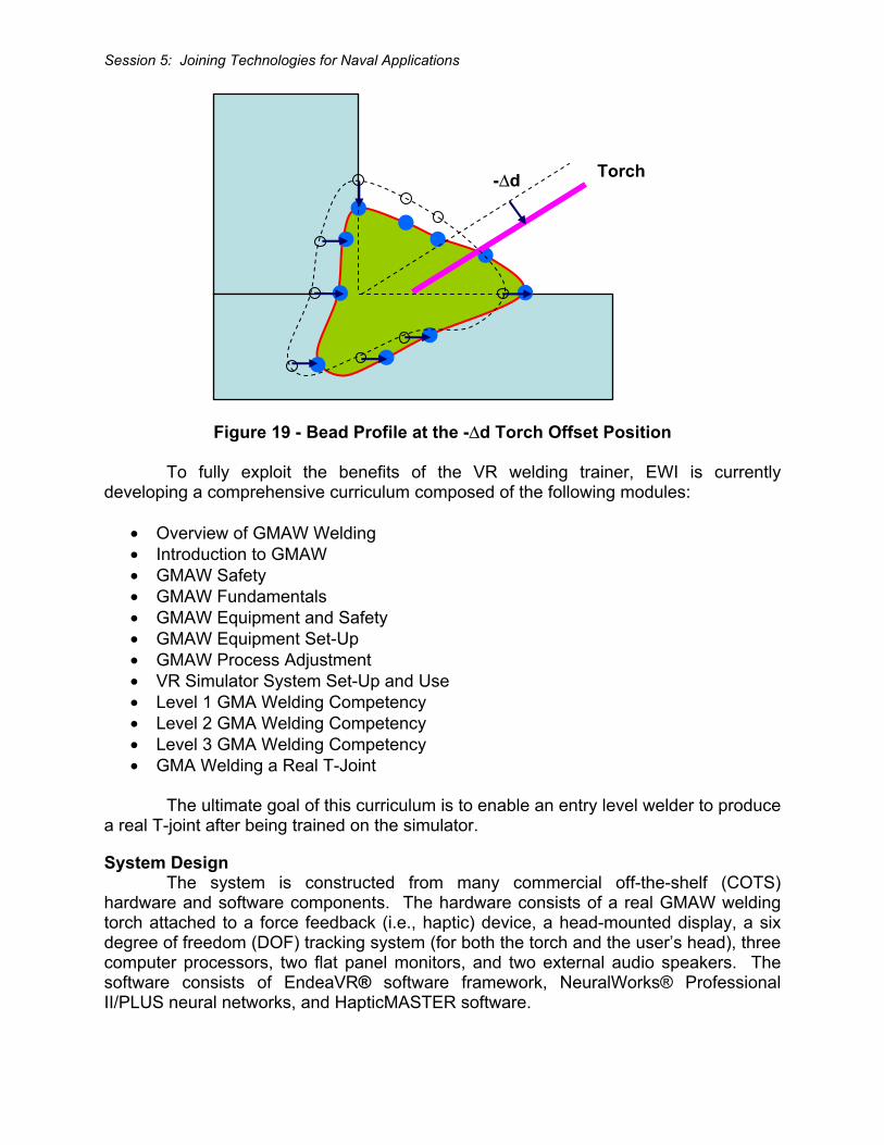
The affect of aim error on resultant bead profile was also identified for improvement in the second year of work, but again, sufficient funds were not available to model this characteristic. With the weld pool model, a reasonably accurate weld bead cross section can be predicted for a given set of parameters. If the torch is perfectly positioned in the T-joint, it will result in the weld bead profile shown in Figure 17. This is considered the "zero" offset location for the torch (boundary nodes are shown as circles). For the purposes of the welding simulation, the aim error (i.e., torch offset) was taken into account by geometrically translating the boundary nodes. Figure 18 shows the location of the boundary nodes (solid blue dots) when the torch is moved upward (i.e., when torch offset is greater than zero). Translation vectors of boundary
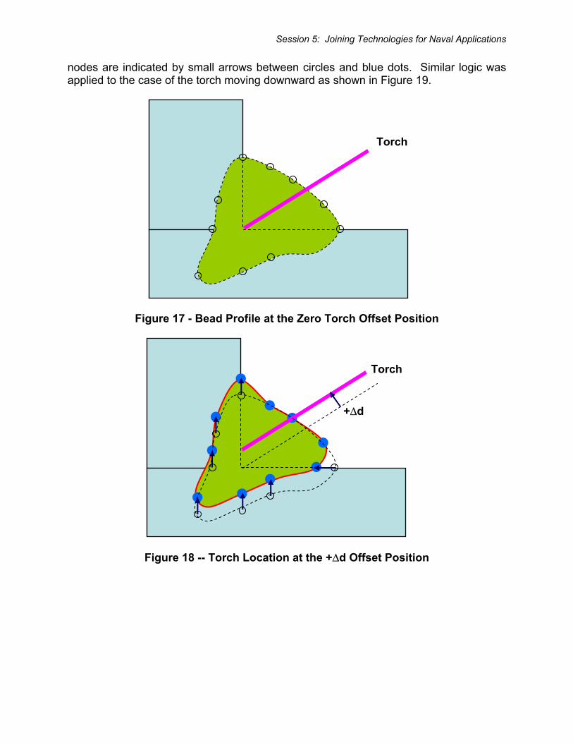
Session 5: Joining Technologies for Naval Applications
nodes are indicated by small arrows between circles and blue dots. Similar logic was applied to the case of the torch moving downward as shown in Figure 19.
Figure 17 - Bead Profile at the Zero Torch Offset Position
Figure 18 -- Torch Location at the +Δd Offset Position
Torch
Torch
+Δd
Session 5: Joining Technologies for Naval Applications
Figure 19 - Bead Profile at the -Δd Torch Offset Position
To fully exploit the benefits of the VR welding trainer, EWI is currently developing a comprehensive curriculum composed of the following modules:
• Overview of GMAW Welding • Introduction to GMAW • GMAW Safety • GMAW Fundamentals • GMAW Equipment and Safety • GMAW Equipment Set-Up • GMAW Process Adjustment • VR Simulator System Set-Up and Use • Level 1 GMA Welding Competency • Level 2 GMA Welding Competency • Level 3 GMA Welding Competency • GMA Welding a Real T-Joint
The ultimate goal of this curriculum is to enable an entry level welder to produce a real T-joint after being trained on the simulator.
System Design The system is constructed from many commercial off-the-shelf (COTS) hardware and software components. The hardware consists of a real GMAW welding torch attached to a force feedback (i.e., haptic) device, a head-mounted display, a six degree of freedom (DOF) tracking system (for both the torch and the user’s head), three computer processors, two flat panel monitors, and two external audio speakers. The software consists of EndeaVR® software framework, NeuralWorks® Professional II/PLUS neural networks, and HapticMASTER software.
Torch -Δd
Session 5: Joining Technologies for Naval Applications
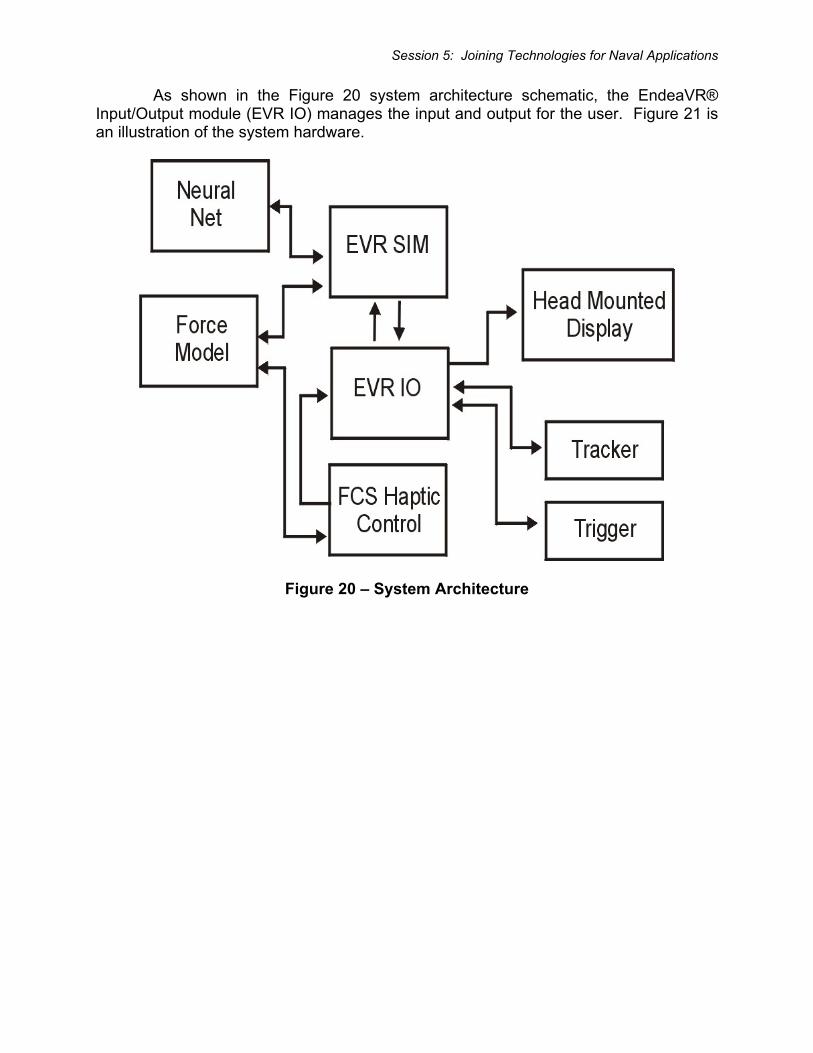
As shown in the Figure 20 system architecture schematic, the EndeaVR® Input/Output module (EVR IO) manages the input and output for the user. Figure 21 is an illustration of the system hardware.
Figure 20 – System Architecture
Session 5: Joining Technologies for Naval Applications
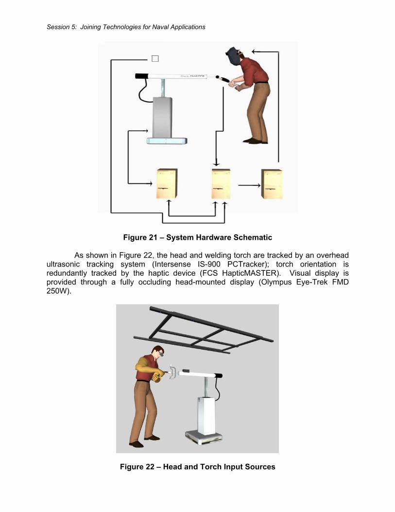
Figure 21 – System Hardware Schematic
As shown in Figure 22, the head and welding torch are tracked by an overhead ultrasonic tracking system (Intersense IS-900 PCTracker); torch orientation is redundantly tracked by the haptic device (FCS HapticMASTER). Visual display is provided through a fully occluding head-mounted display (Olympus Eye-Trek FMD 250W).
Figure 22 – Head and Torch Input Sources
Session 5: Joining Technologies for Naval Applications
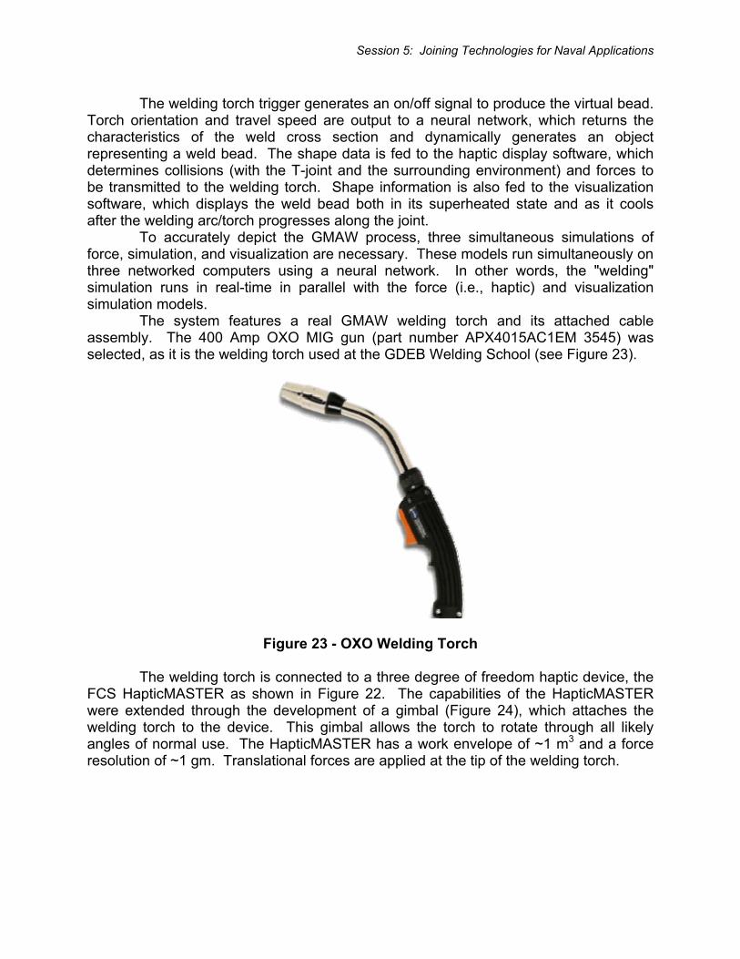
The welding torch trigger generates an on/off signal to produce the virtual bead. Torch orientation and travel speed are output to a neural network, which returns the characteristics of the weld cross section and dynamically generates an object representing a weld bead. The shape data is fed to the haptic display software, which determines collisions (with the T-joint and the surrounding environment) and forces to be transmitted to the welding torch. Shape information is also fed to the visualization software, which displays the weld bead both in its superheated state and as it cools after the welding arc/torch progresses along the joint. To accurately depict the GMAW process, three simultaneous simulations of force, simulation, and visualization are necessary. These models run simultaneously on three networked computers using a neural network. In other words, the "welding" simulation runs in real-time in parallel with the force (i.e., haptic) and visualization simulation models. The system features a real GMAW welding torch and its attached cable assembly. The 400 Amp OXO MIG gun (part number APX4015AC1EM 3545) was selected, as it is the welding torch used at the GDEB Welding School (see Figure 23).
Figure 23 - OXO Welding Torch
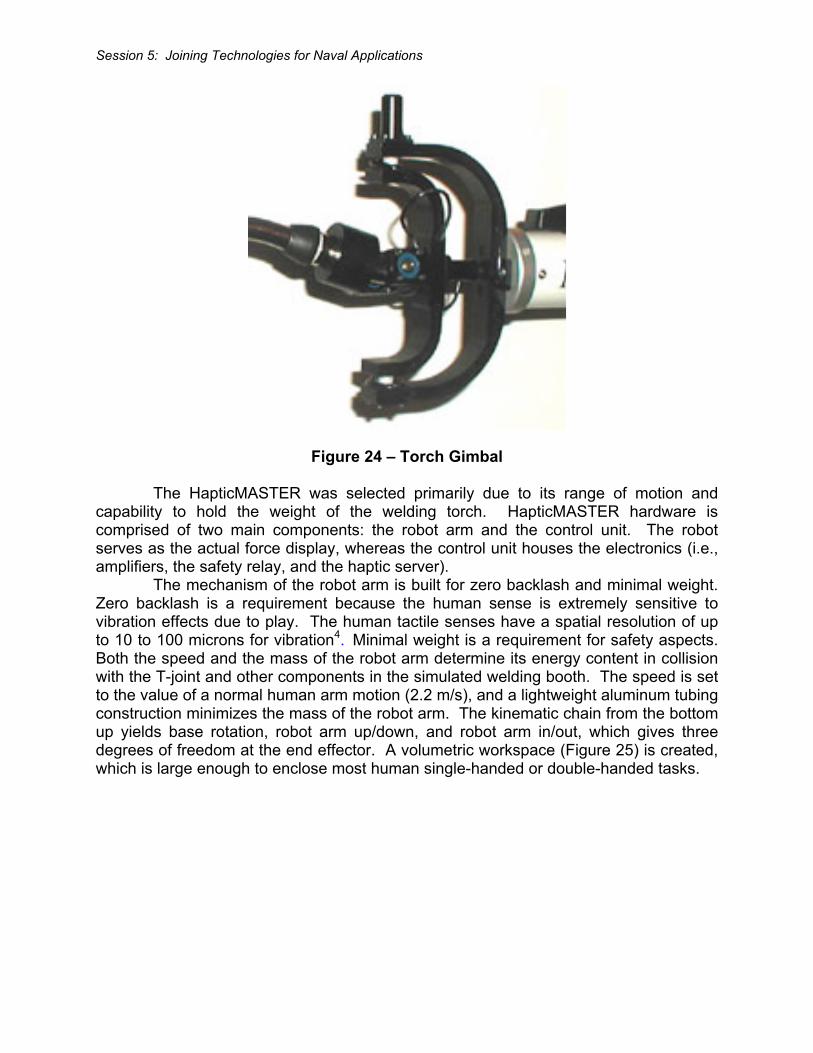
The welding torch is connected to a three degree of freedom haptic device, the FCS HapticMASTER as shown in Figure 22. The capabilities of the HapticMASTER were extended through the development of a gimbal (Figure 24), which attaches the welding torch to the device. This gimbal allows the torch to rotate through all likely angles of normal use. The HapticMASTER has a work envelope of ~1 m3 and a force resolution of ~1 gm. Translational forces are applied at the tip of the welding torch.
Session 5: Joining Technologies for Naval Applications
Figure 24 – Torch Gimbal
The HapticMASTER was selected primarily due to its range of motion and capability to hold the weight of the welding torch. HapticMASTER hardware is comprised of two main components: the robot arm and the control unit. The robot serves as the actual force display, whereas the control unit houses the electronics (i.e., amplifiers, the safety relay, and the haptic server). The mechanism of the robot arm is built for zero backlash and minimal weight. Zero backlash is a requirement because the human sense is extremely sensitive to vibration effects due to play. The human tactile senses have a spatial resolution of up to 10 to 100 microns for vibration4. Minimal weight is a requirement for safety aspects. Both the speed and the mass of the robot arm determine its energy content in collision with the T-joint and other components in the simulated welding booth. The speed is set to the value of a normal human arm motion (2.2 m/s), and a lightweight aluminum tubing construction minimizes the mass of the robot arm. The kinematic chain from the bottom up yields base rotation, robot arm up/down, and robot arm in/out, which gives three degrees of freedom at the end effector. A volumetric workspace (Figure 25) is created, which is large enough to enclose most human single-handed or double-handed tasks.
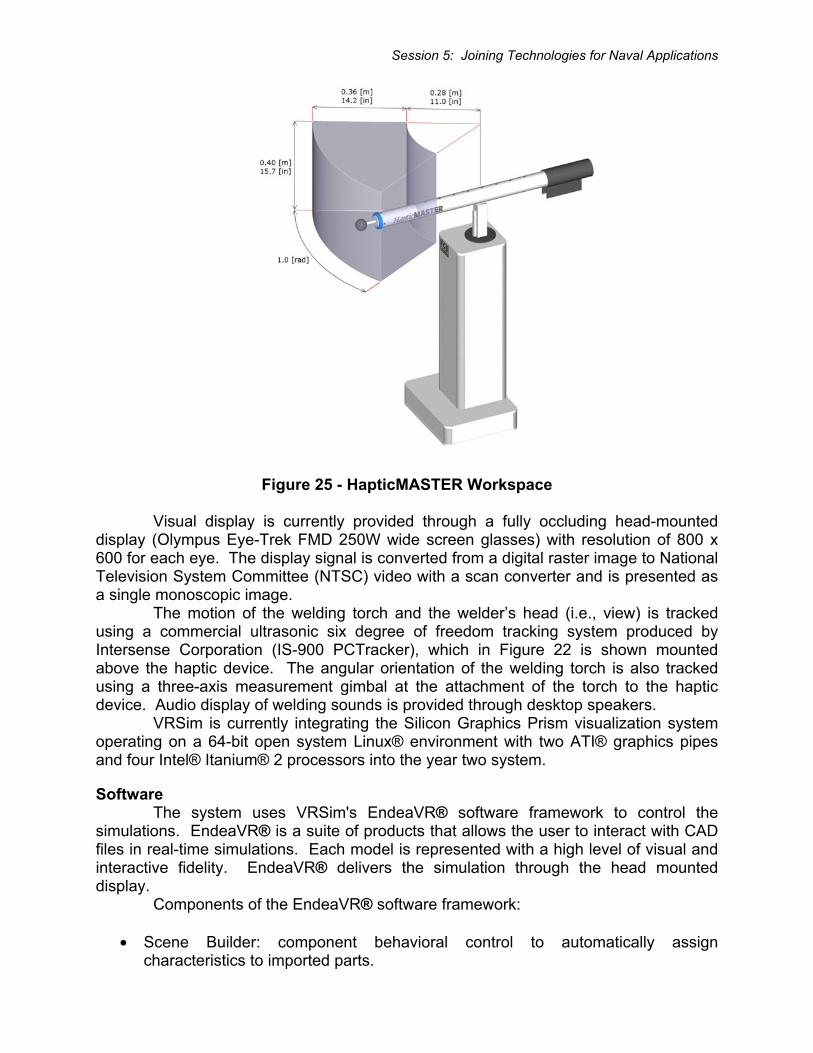
Session 5: Joining Technologies for Naval Applications
Figure 25 - HapticMASTER Workspace
Visual display is currently provided through a fully occluding head-mounted display (Olympus Eye-Trek FMD 250W wide screen glasses) with resolution of 800 x 600 for each eye. The display signal is converted from a digital raster image to National Television System Committee (NTSC) video with a scan converter and is presented as a single monoscopic image. The motion of the welding torch and the welder’s head (i.e., view) is tracked using a commercial ultrasonic six degree of freedom tracking system produced by Intersense Corporation (IS-900 PCTracker), which in Figure 22 is shown mounted above the haptic device. The angular orientation of the welding torch is also tracked using a three-axis measurement gimbal at the attachment of the torch to the haptic device. Audio display of welding sounds is provided through desktop speakers. VRSim is currently integrating the Silicon Graphics Prism visualization system operating on a 64-bit open system Linux® environment with two ATI® graphics pipes and four Intel® Itanium® 2 processors into the year two system.
Software The system uses VRSim's EndeaVR® software framework to control the simulations. EndeaVR® is a suite of products that allows the user to interact with CAD files in real-time simulations. Each model is represented with a high level of visual and interactive fidelity. EndeaVR® delivers the simulation through the head mounted display. Components of the EndeaVR® software framework:
• Scene Builder: component behavioral control to automatically assign characteristics to imported parts.
Session 5: Joining Technologies for Naval Applications
• Easy Objects: preconstructed tools and components for plug and play use within the simulation.
• VRmath: provides fast high level calculations to enhance the dynamics of the real time simulation.
The neural net trained by EWI is the NeuralWorks® Professional II/PLUS, a state-of-the-art software tool for rapidly creating and deploying prediction and classification applications with a proven record of usage for various welding applications. NeuralWorks® Professional II/PLUS was selected due to its performance in the following areas:
• User friendly graphical interface • Major network types are supported (necessary to choose appropriate neural
network topology for adequate and accurate modeling of welding specific applications).
• Modification and adjustment of the network architecture is very flexible (this functionality is absolutely necessary since extension of the network architecture will be needed to include additional welding process variables in year two of this project).
• Trained network has excellent deployment capability (required to generate standard C/Fortran code to deploy and integrate trained network into simulator hardware).
The HapticMASTER is controlled by a software module provided by FCS, which integrates with the I/O module (EVR IO in Figure 20). The HapticMASTER’s virtual model is rendered by a dedicated personal computer with a VxWorks real-time operating system (called the haptic server), which runs at a fixed 2,500 Hz refresh rate. This frequency is assumed to be high enough to guarantee haptic quality for a smooth and realistic experience, since it is approximately ten times higher than the maximal human discrepancy value5. Finally, the proportional integration and derivative (PID) motor control loop runs on the amplifiers (located in the control box) at a 20 kHz pulse width modulated frequency. With an application programming interface (API), the user creates the virtual model on the haptic server. The real-time operating system on the haptic server interprets the virtual model and generates the trajectories for the robot, based on the force sensor input. The haptic server also incorporates issues like safety guards, communication protocols, and collision detection with virtual objects. The HapticAPI, which is a C++ programming interface, is used to make an Ethernet connection to the HapticMASTER to control the internal state machine and to define or modify the virtual haptic world. Haptic effects can be created (like dampers and springs), and spatial geometric primitives can be defined (like spheres, cones and cubes). Simple virtual worlds can be created using these effects and primitives. When more complex virtual worlds are required, e.g. with meshed surfaces or deformation, another rendering method needs to be applied. A local mass model will be rendered on the haptic server, and the forces acting on this mass due to interaction with the virtual world are rendered from a host PC. When the end effector collides with a virtual object, an appropriate force and displacement are presented to the user. The relationship between force and
Session 5: Joining Technologies for Naval Applications
displacement is given by the object properties of the virtual model (e.g. stiffness, damping, friction, etc.). Using a penalty-based method, the appropriate relation between force and displacement is calculated by the real-time operating system and incorporated in the position, velocity, and acceleration (PVA) signal. The HapticMASTER uses an admittance control algorithm. A force sensor measures the interaction force between the user and the system. From these forces a virtual mass model calculates the PVA, which an object touched in the virtual world would obtain as a result of this force. The virtual world defines the space in which the object lives (e.g. gravity, environmental friction, position of the object, etc.) and the object properties (e.g. mass, stiffness, damping, friction, etc.). The virtual mass model will typically contain a mass larger than zero, to avoid commanding infinite accelerations and cause system instabilities. The PVA-vector serves as a reference signal for the robot, realized by a PID servo control servo loop. With proper feedback gain settings, this control loop will compensate for the real mass of the manipulator up to a factor of six, and terminates its internal friction up to the accuracy of the force sensor. Therefore, if the mass of the manipulator behind the actuator is 15 kg, the operator feels only 2.5 kg at the end effector. Since gravity can also be eliminated (if desired), it does not feel like moving 2.5 kg. For the GMAW simulation, the use feels the full weight of the welding torch and its attached cable assembly.
Simulator Operation VRSim's EndeaVR® virtual reality operating system manages all aspects of the simulation. The EndeaVR® simulation module (EVR SIM in Figure 20) handles all aspects of software behavior control of virtual objects. The EndeaVR® Input/Output module (EVR IO in Figure 20) manages the input and output with the user. This includes input from the tracking system, which gives the system the position and orientation of the users head, as well as, maintaining the calibration of the relative positions of the head mounted display (HMD) and the HapticMASTER. The EVR IO also creates the output to the HMD. The torch trigger feeds an on/off signal that generates the virtual bead. The torch orientation and travel speed are output to the neural net, which returns the geometric characteristics that dynamically generate weld bead shape based on cross section predictions. The shape data is also fed to the haptic display software, which determines collisions with the weld test piece (and the resultant forces) to be transmitted to the torch. Shape information is also fed to the visualization software, which displays the bead both in its superheated state and as it cools behind the travel path of the welding arc. The welding simulation is currently based on empirical results from the detailed analysis of the forty-three test welds and is generated by three computers running simultaneous virtual models of force, simulation and visualization. The weld pool graphics are currently being improved by moving away from a neural net trained solely with the measurements of physical welds to a series of neural nets trained by a combination of numerical modeling and physical measurements. In real-time, the neural net software communicates directly with the simulation module (EVR SIM). The EVR SIM module calculates the position, orientation and speed of the welding torch based on information from the tracking devices. These
Session 5: Joining Technologies for Naval Applications
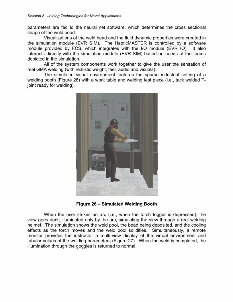
parameters are fed to the neural net software, which determines the cross sectional shape of the weld bead. Visualizations of the weld bead and the fluid dynamic properties were created in the simulation module (EVR SIM). The HapticMASTER is controlled by a software module provided by FCS, which integrates with the I/O module (EVR IO). It also interacts directly with the simulation module (EVR SIM) based on needs of the forces depicted in the simulation. All of the system components work together to give the user the sensation of real GMA welding (with realistic weight, feel, audio and visuals). The simulated visual environment features the sparse industrial setting of a welding booth (Figure 26) with a work table and welding test piece (i.e., tack welded T-joint ready for welding).
Figure 26 – Simulated Welding Booth
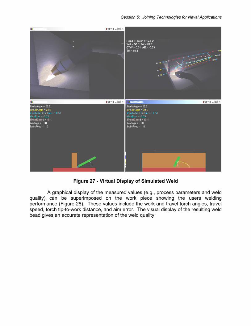
When the user strikes an arc (i.e., when the torch trigger is depressed), the view goes dark, illuminated only by the arc, simulating the view through a real welding helmet. The simulation shows the weld pool, the bead being deposited, and the cooling effects as the torch moves and the weld pool solidifies. Simultaneously, a remote monitor provides the instructor a multi-view display of the virtual environment and tabular values of the welding parameters (Figure 27). When the weld is completed, the illumination through the goggles is returned to normal.
Session 5: Joining Technologies for Naval Applications
Figure 27 - Virtual Display of Simulated Weld
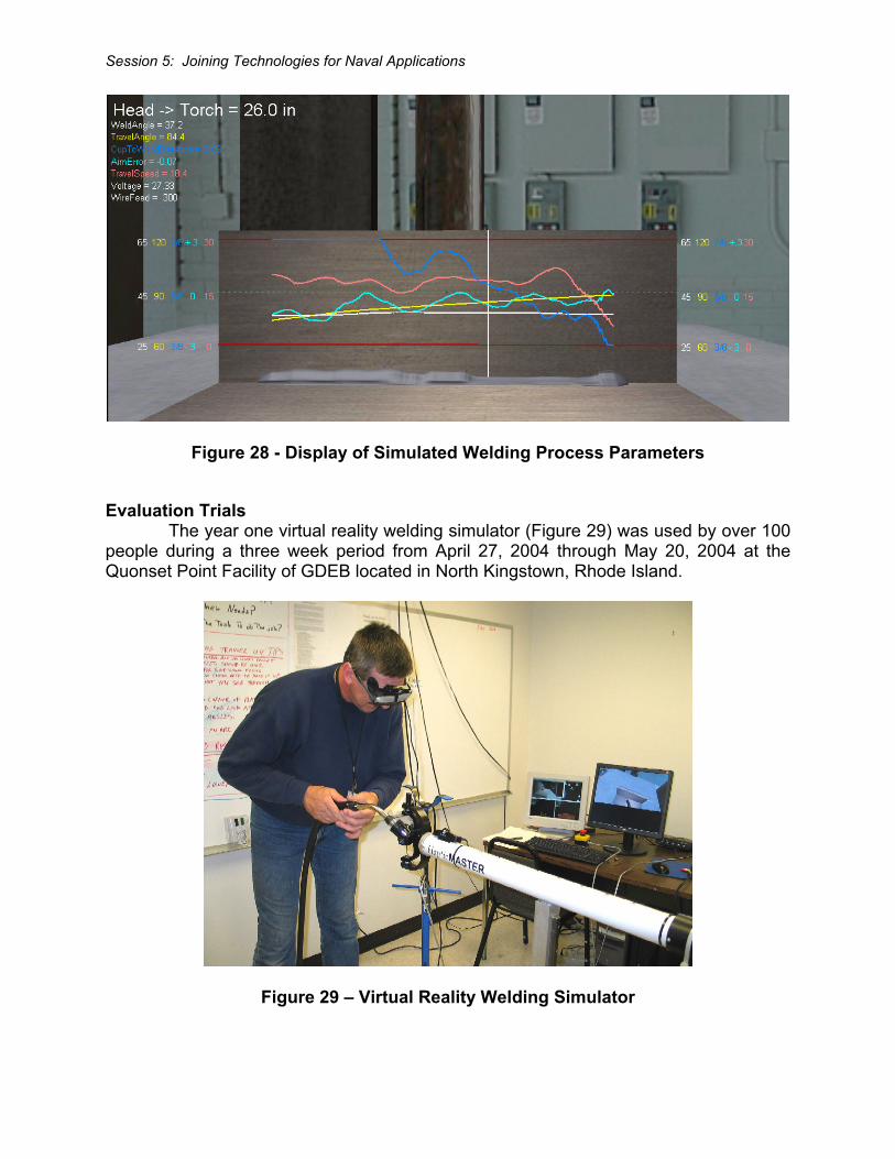
A graphical display of the measured values (e.g., process parameters and weld quality) can be superimposed on the work piece showing the users welding performance (Figure 28). These values include the work and travel torch angles, travel speed, torch tip-to-work distance, and aim error. The visual display of the resulting weld bead gives an accurate representation of the weld quality.
Session 5: Joining Technologies for Naval Applications
Figure 28 - Display of Simulated Welding Process Parameters
Evaluation Trials The year one virtual reality welding simulator (Figure 29) was used by over 100 people during a three week period from April 27, 2004 through May 20, 2004 at the Quonset Point Facility of GDEB located in North Kingstown, Rhode Island.
Figure 29 – Virtual Reality Welding Simulator
Session 5: Joining Technologies for Naval Applications
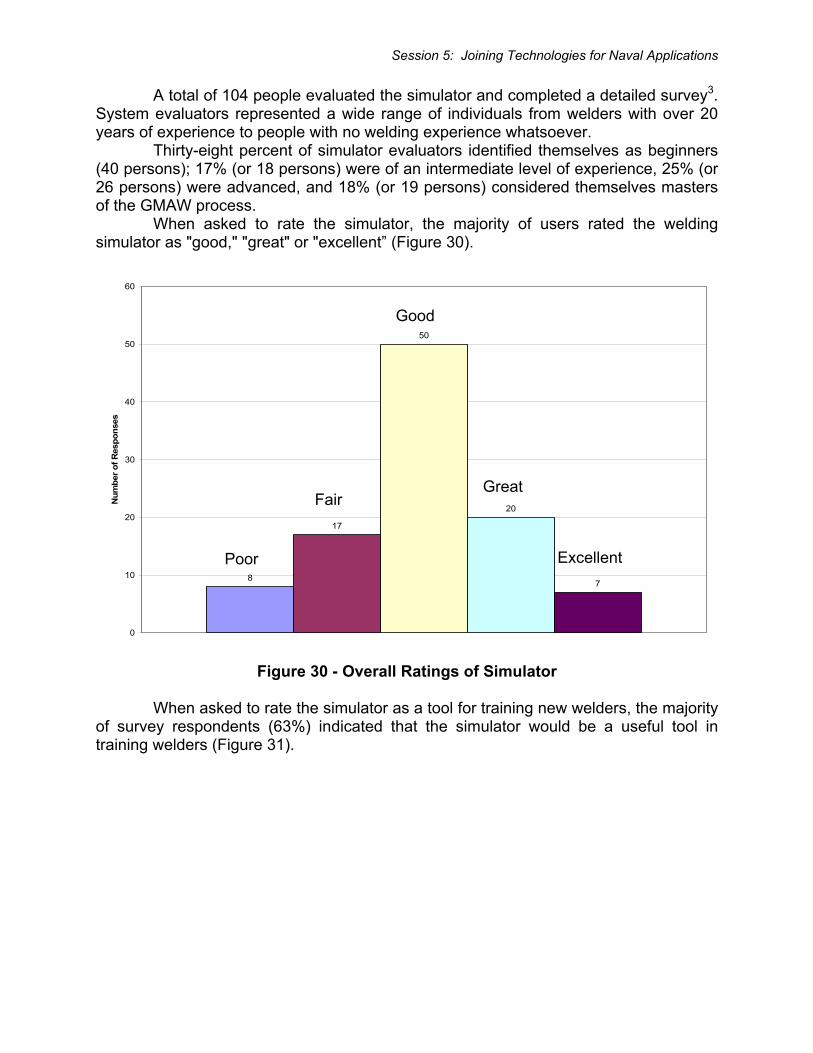
A total of 104 people evaluated the simulator and completed a detailed survey3. System evaluators represented a wide range of individuals from welders with over 20 years of experience to people with no welding experience whatsoever. Thirty-eight percent of simulator evaluators identified themselves as beginners (40 persons); 17% (or 18 persons) were of an intermediate level of experience, 25% (or 26 persons) were advanced, and 18% (or 19 persons) considered themselves masters of the GMAW process. When asked to rate the simulator, the majority of users rated the welding simulator as "good," "great" or "excellent” (Figure 30).
Figure 30 - Overall Ratings of Simulator
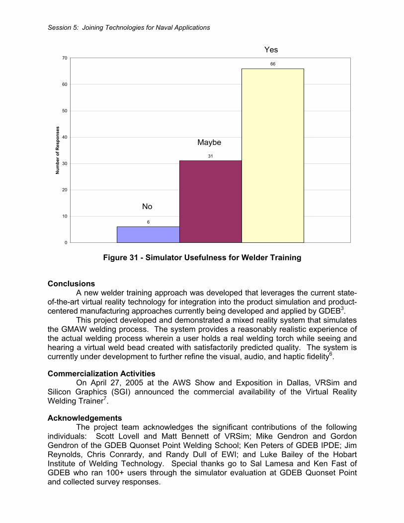
When asked to rate the simulator as a tool for training new welders, the majority of survey respondents (63%) indicated that the simulator would be a useful tool in training welders (Figure 31).
8
17
50
20
7
0
10
20
30
40
50
60
Num
ber o
f Res
pons
es
Excellent
Great
Good
Fair
Poor
Session 5: Joining Technologies for Naval Applications
Figure 31 - Simulator Usefulness for Welder Training
Conclusions A new welder training approach was developed that leverages the current state-of-the-art virtual reality technology for integration into the product simulation and product-centered manufacturing approaches currently being developed and applied by GDEB3. This project developed and demonstrated a mixed reality system that simulates the GMAW welding process. The system provides a reasonably realistic experience of the actual welding process wherein a user holds a real welding torch while seeing and hearing a virtual weld bead created with satisfactorily predicted quality. The system is currently under development to further refine the visual, audio, and haptic fidelity6.
Commercialization Activities On April 27, 2005 at the AWS Show and Exposition in Dallas, VRSim and Silicon Graphics (SGI) announced the commercial availability of the Virtual Reality Welding Trainer7.
Acknowledgements The project team acknowledges the significant contributions of the following individuals: Scott Lovell and Matt Bennett of VRSim; Mike Gendron and Gordon Gendron of the GDEB Quonset Point Welding School; Ken Peters of GDEB IPDE; Jim Reynolds, Chris Conrardy, and Randy Dull of EWI; and Luke Bailey of the Hobart Institute of Welding Technology. Special thanks go to Sal Lamesa and Ken Fast of GDEB who ran 100+ users through the simulator evaluation at GDEB Quonset Point and collected survey responses.
6
31
66
0
10
20
30
40
50
60
70N
umbe
r of R
espo
nses
No
Maybe
Yes
Session 5: Joining Technologies for Naval Applications
References 1 Boutwell, R., “Welding Training Modernization”, SNAME Ship Production
Symposium, Boston, 2002 2 Waterworth, J., “Survey of Medical Applications of Virtual Reality”, Umeå
University, Dept. of Informatics Research Report #9802, 1998 3 Porter, N., Yancey, R., Reynolds, J., Cote, A., Peters, K., Fast, K., Gifford, T.,
Dudac, Y., and Lam, W., “Virtual Reality for Welder Training,” EWI Report, Project No. 47253GDE (July 2004).
4 Burdea, G., “Force and Touch Feedback for Virtual Reality." John Wiley & Sons, New York, USA, 1996.
5 Amirabdollahiam, F., Loureiro, R., and Harwin, W., "A Case Study on the Effects of a Haptic Interface on Human Arm Movements with Implications for Rehabilitation Robotics." Proceedings of 1st Cambridge Workshop on Universal Access and Assistive Technology. University of Cambridge, Cambridge, UK, 2002.
6 Porter, N., “Virtual Training for Welding Phase II,” EWI Plan of Action and Milestones, Project No. 47253GDE (May 2004).
7 Loskot, V., “SGI and VRSim Debut Immersive Virtual Reality Welding Trainer,” Silicon Graphics News Release (April 2005).