virtual design of a machine tool feed drive system · · 2010-03-02virtual design of a machine...
TRANSCRIPT

U.P.B. Sci. Bull., Series D, Vol. 71, Iss. 4, 2009 ISSN 1454-2358
VIRTUAL DESIGN OF A MACHINE TOOL FEED DRIVE SYSTEM
Radu Constantin PARPALĂ 1
In zilele noastre, constructorii de maşini-unelte nu mai pot irosi timp şi resurse construind şi testand prototipuri reale ale maşinilor-unelte, în locul prototipurilor reale folosind prototipuri virtual. In acest articol este prezentat stadiul actual al proiectarii virtuale a maşinilor unelte folosind ca studiu de caz lanţul cinematic de avans poziţionare. Comportarea statică şi dinamică este evaluată pentru obţinerea unui model optimizat al lanţului cinematic de avans al maşinii-unelte. Folosind metodele specifice proiectării virtuale, inginerii pot reduce timpul necesar proiectării astfel reducându-se durata necesară lansării unui produs nou pe piaţă.
Today, machine tool manufacturers can no longer afford to consume time
and money building and testing real prototypes of the machine tool model, instead they use virtual prototypes. This paper presents the current state of virtual prototyping of a virtual machine tool; the work focuses on the design of the feed drive system. The structural behavior under static and dynamic loads is evaluated in order to obtain an optimized design of the feed drive. The following steps are detailed in the paper: - Importing the 3D model, - Defeaturing of the 3D model and setup of the Finite Element model, - Optimization of the mesh structure. Using Virtual Prototyping techniques, engineers are able to shorten the design time and therefore to shorten the time needed for pushing to market new products.
Keywords: FE model, Mesh, design modeler.
1. Introduction
In the virtual prototype approach one is able to simulate the kinematic,
static and dynamic behavior of the machine tool including all aspects of real life exploitation. Using different software packages one is able to simulate even the cutting process. This complex design concept was enabled by the use of high performance computer technology.
Several types of analyses must be performed for a complete study of the machine tool behavior. The results of some simulations can be further used as input for other analyses. For example, from the cutting process analyses we use forces as input for the dynamic finite element (FE) simulation.
1 Phd Student, University POLITEHNICA of Bucharest, Romania, e-mail: [email protected]
132 Radu Constantin Parpală
This paper presents the current state of virtual prototyping of a virtual machine tool. The work focuses on the design of the feed drive system. The main aspects of virtual design concept covered by this paper are the structural and dynamic analysis of a machine tool feed drive using the finite element method. The following steps are detailed in the paper: Defeaturing of the 3D model and the setup of the FE model.
Unfortunately at the moment there are no integrated software platforms for the virtual design and analysis of the machine tools. As a result, there are many problems that appear when importing models from between different software applications.
Because of the impact of the feed drives imply on the quality of the finite piece the design demands are very high. That is why accurate analyses must be performed in order to assure a very good behavior of the whole machine tool.
2. Computer Aided Design
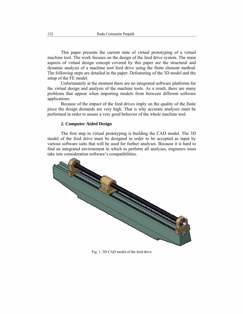
The first step in virtual prototyping is building the CAD model. The 3D model of the feed drive must be designed in order to be accepted as input by various software suits that will be used for further analyses. Because it is hard to find an integrated environment in which to perform all analyses, engineers must take into consideration software’s compatibilities.
Fig. 1. 3D CAD model of the feed drive

Virtual design of a machine tool feed drive system 133
During the design phase simplified simulation models are used to estimate the impact of design parameters over the machine performance. These simplified models are also used in order to improve the time needed for calculation and to eliminate the computing errors. It is well known that a very complex model can generate errors during the FE analysis. Because of this, many features from the 3D model are eliminated. Also, some details that are essential for FE analyses are not so important for a kinematic analyze and must be ignored. A CAD model must be easily redesigned so it is important to use parameters to define all the key elements of the model.
The 3D model of the feed drive was designed using the CATIA V5 CAD software mainly because of its good integration with the ANSYS software which was used for static and dynamic FE analyses. All 3D part where fully parameterized in order to optimize needed parameters in FE analyses.
In order to generate all the contacts between surfaces it’s necessary to correctly design the 3D assembly, it is also very useful to check all the clashes and clearances within the CAD environment. Using the information provided by the CAD software, we can set the correct tolerances for the automatic contact generation.
Fig. 2. Section through 3D model

134 Radu Constantin Parpală
Fig. 3. Space analysis of the 3D model
As a main phase in the design process, the kinematic analysis can be
useful because during this simulation all the components move relative to each other respecting the assembly constrains. During this simulation, the mecatronical system can be observed in different stages and it is possible to freeze one position which can be latter imported into the FEM software.
The CATIA software provides some very useful tools for space analysis. In Figure 2 it is an example of a misplaced component. In this case the, error is detectable by a visual inspection of the model but sometimes the errors are undetectable by the human eye so the check clash tool must be used (Figure 3). This tool is very important as it calculates all the distances between the assembly components. Those distances can be further used as an input in FEM software in order to generate correct contact surfaces.
Because we need to use the 3D model for further analyses it is a good practice to define also material properties by using predefined model from the CATIA library or by defining new materials. By defining material properties we can also check important aspects of the assembly like volume, mass, moment of inertia, etc.
Some of those information are computed by the FE software. In this way we can check if all the components are imported correctly (material properties, units, volumes, etc.).

Virtual design of a machine tool feed drive system 135
Fig. 4. CATIA inertia measurement tool
3. ANSYS FE analysis
The ANSYS Workbench platform is an environment that offers an efficient and intuitive user interface, superior CAD integration, automatic meshing, and access to model parameters as well as to the functionality available within the ANSYS Mechanical products. Because of the good integration between CATIA V5R15 and ANSYS Workbench we have decided to use this specialized FE software for our static and dynamic analysis.
Because the model was not designed in ANSYS Workbench native CAD system, we must first check if all the model’s features are imported before we proceed to further analyses (Fig. 4).
Getting the geometry in Design Modeler, simulation or advanced meshing is now much easier than in almost any other FEM software. The first thing to know about formats is that there are readers and plug-ins. Readers simply translate the CAD format into workbench’s internal format. A plug-in actually uses software from the CAD vendor and opens up the geometry in the native format and gives the workbench all the information it needs in native format. Often the geometry provided by readers is referred as dumb and plug-in geometry as smart because this kind of geometry can be transferred back to the CAD files. It’s a good practice to import all the parts into the Design Modeler before proceeding to simulation.
136 Radu Constantin Parpală
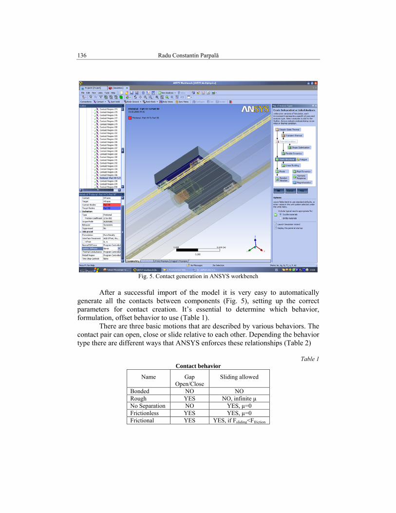
Fig. 5. Contact generation in ANSYS workbench
After a successful import of the model it is very easy to automatically
generate all the contacts between components (Fig. 5), setting up the correct parameters for contact creation. It’s essential to determine which behavior, formulation, offset behavior to use (Table 1).
There are three basic motions that are described by various behaviors. The contact pair can open, close or slide relative to each other. Depending the behavior type there are different ways that ANSYS enforces these relationships (Table 2)
Table 1
Contact behavior
Name Gap Open/Close
Sliding allowed
Bonded NO NO Rough YES NO, infinite µ No Separation NO YES, µ=0 Frictionless YES YES, µ=0 Frictional YES YES, if Fsliding<Ffriction

Virtual design of a machine tool feed drive system 137
Table 2 Contact calculation
Name Equation Solved Default Contact Detection
MPC Generate GE’s Nodes Pure Penalty F=kx Gauss
Augmented Lagrange F= kx + λ Gauss Normal Lagrange Nodal Pressure DOF Node
The MPC (Multipoint Constraint) method simply writes constraint equations between the contacting bodies. Pure penalty enforce contact stiffness for a given penetration. The Augmented Lagrange is similar to Pure Penalty, except that it includes a factor for contact pressure to eliminate some chattering effect.
The Normal Lagrange adds a Contact Pressure DOF to the model. In terms of runtime, the formulations shown are listed in increasing run time.
There is a strong connection between contact generation and mesh generation. For a proper meshed structure it is necessary to repair the geometry before any further operations.
The main purpose of the CAD repair tool is to detect and close gaps between neighboring surfaces. Typically, this procedure involve two steps: 1. Build topology – build curves and points which will help to diagnose the model for geometrical problems. If the curves are within a geometric tolerance, they are merged together as one. The curves are then displayed in a specific color to illustrate their connectivity in the surface data, which can be used to determine any gaps or holes in the geometry (Figure 6). 2. Repair any gaps or hole in the topology.
For any two faces (surfaces) that meet at a common edge (curve), there is typically a finite distance between the two edges. By default, a curve is associated with all the edges of each face. This topology of the two surfaces would indicate a gap in the model.
Typically, ANSYS meshers can handle this if the gap is smaller than the proposed element size on the surfaces or curves. Therefore, you would set a tolerance larger than the gap if you are using a large element size.
Table 2
Build Topology Colors
Color Semnification Yellow Single or free edge curves Red Double edge curves Blue Multiple edge curves Green Unattached curves

138 Radu Constantin Parpală
Fig. 6. Mesh quality
A tolerance smaller than the gap would create yellow curves which could
be fixed. The recommended tolerance is approximately 1/10th the size of the average mesh size.
A tolerance smaller than the gap would create yellow curves which could be fixed. The recommended tolerance is approximately 1/10th the size of the average mesh size.
The quality of the mesh needs to be checked before applying loads and constraints. It gives an idea of how close the mesh is to an ideal mesh.
Quality can be measured by the various criteria. For Hexa dominant meshes the quality is calculated as the determinant. The Determinant, more properly defined as the relative determinant, is the ratio of the smallest determinant of the Jacobian matrix divided by the largest determinant of the Jacobian matrix, where each determinant is computed at each node of the element. The Determinant can be found for all linear hexahedral, quadrahedral, and pyramidal elements. A Determinant value of 1 would indicate a perfectly regular mesh element, 0 would indicate an element degenerate in one or more edges, and negative values would indicate inverted elements.
To automatically improve the quality of the mesh elements. Different smoothing algorithms are available depending on which mesh type is loaded.

Virtual design of a machine tool feed drive system 139
Fig. 7. Manual change mesh quality Mesh can be smoothed with respect to a particular quality criterion and
with a specified number of iterations to achieve a given quality level. A mesh containing tetras, pyramids, prisms and triangular and quad surface elements can be smoothed.
The mesh can be also improved manually by moving nodes. An example is shown in Fig. 7 where some nodes where moved. As a result, we have in the left side of the figure a smother mesh. This can be checked by visualizing element colors. Those colors change as the form of the elements changes.
6. Conclusions
Using a set of dedicated software, engineers are able to analyze and optimize many aspects of real life usage of machine tool elements without spending money on real prototypes and this could bring important time and money savings.
By using ANSYS Workbench it is possible to optimize the design process by changing one or more of the initial parameters; those parameters are automatically updated into the CATIA 3D CAD model. By analyzing the calculation result in the post-processing program the designers can evaluate the machine properties during the design stage.
Today the main problem in checking structures consists in importing and preprocessing the CAD model. It is well known that the geometry of the model can dramatically change FE results
Initiated mainly by the automotive and aircraft industry, the development of modern software tools for integrated simulation of products has been enchanted lately. Unfortunately at the moment there are no integrated software platform for the virtual design and analysis of the machine tools.
140 Radu Constantin Parpală
R E F E R E N C E S
[1] Y. Altintas, C. Brecher, M. Weck & S. Witt, Virtual machine tool, Annals of the CIRP , 54/2: 651 – 669,2005.
[2] M. Zaeh, & Th. Oertli, Finite Element Modeling of Ball Screw Feed Drive Systems, Annals of the CIRP, 53/1: 289-292, 2004
[3] H. Groß, & J. Hamann, Electrical Feed Drives in Automation. Basics, Computation, Dimensioning. Siemens, Publicis MCD Corporate Publishing, Erlangen and Munich, 2001
[4] M. Weck, Werkzeugmaschinen. Mechatronishce Systeme, Vorschube, Prozeßdiagnose., Springer-Verlag, Berlin, Heidelberg, ISBN 3-540-67614, 2001
[5] ***. The FOCUS, Issue 61, 13 December 2007 available on www.ansys.com [6] ***. Ansys Advantage, volume II, Issue 3, 2008 available on www.ansys.com [7] Miron Zapciu, Jean-Yves K’NEVEZ, Raynald Laheurte, Philippe Darnis, Dynamic research
and procedure to obtain a useful domain of dynamometers for machine toolsr, Scientific Bulletin, Series D, Vol. 71, Iss. 1, 2009, ISSN 1454-2358.