virtual automation lab using unity3d and openmodelica · 2020-02-04 · 1 virtual automation lab...
TRANSCRIPT
1
Virtual Automation Lab using Unity3D and OpenModelica
Santosh Desai, BMSCE BengaluruRitesh Sharma, ModeliCon InfoTech LLP
Vasu Goel, ModeliCon InfoTech LLPVidhu Shah, ModeliCon InfoTech LLPSunil Shah, ModeliCon InfoTech LLP
Adeel Asghar, Research Institutes of Sweden RISE
2
Agenda1. Introduction to Virtual Automation Lab (VAL)
2. Components of VAL
3. System Architecture
4. Demonstration
1. Introduction to Virtual Automation Lab(VAL)

4
Motivation1. Access to industry is not easy for engineering students and lack of it is creating
skill gap between industry and academia.
2. Virtual Automation Lab is a project aimed at bridging that gap.
3. Non immersive simulators have limited applications:a. Even best of the simulators can not give realistic experience of an industry.b. Conventional simulators teach system complexity and not usability.
4. A Virtual Reality simulator will allow:a. Interactive operation of machines.b. Interactive learning of industrial sensors and actuators.c. Manual fault detection and correction.d. Operation in auto mode.e. Trainer-operator setup and evaluation.
5
Introduction1. Virtual Automation Lab is a project aimed at building industry grade Virtual
Reality experiences of automation industry for engineering students.
2. It includes:a. A Virtual Reality simulated environments created using Unity 3D,
b. Process simulations running on OpenModelica and
c. PLC/HMI interface running on CodeSys.
3. Each experiment will have two modes of operations: Auto/Manual
4. Manual Mode Operation:In manual mode the inputs to the process simulation model will come from the user via VR hand held controllers.
5. Auto Mode Operation:a. Control signals will come from PIDs tuned by the user.
b. Resulting changes will be visible in VR environment and HMI in both modes.
6
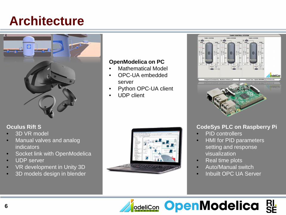
Architecture
Oculus Rift S• 3D VR model• Manual valves and analog
indicators• Socket link with OpenModelica• UDP server• VR development in Unity 3D• 3D models design in blender
OpenModelica on PC• Mathematical Model• OPC-UA embedded
server• Python OPC-UA client• UDP client
CodeSys PLC on Raspberry Pi• PID controllers• HMI for PID parameters
setting and response visualization
• Real time plots• Auto/Manual switch• Inbuilt OPC UA Server
2. Components of VAL(Interacting Tanks Model)
8
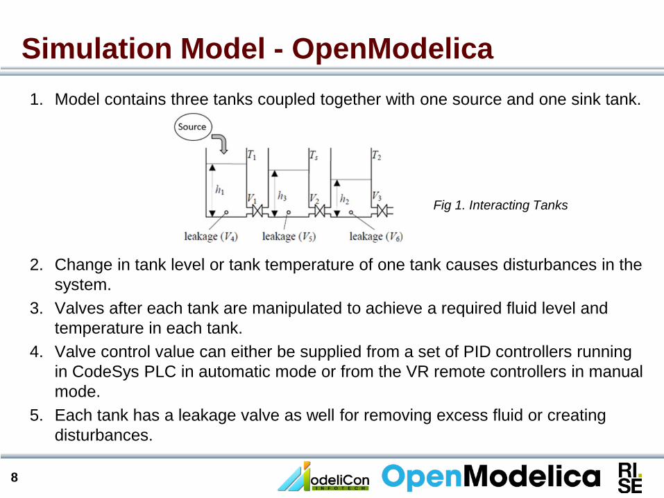
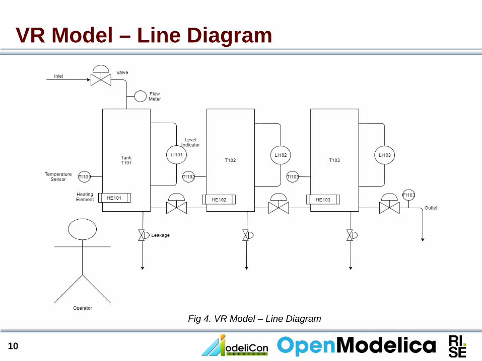
1. Model contains three tanks coupled together with one source and one sink tank.
2. Change in tank level or tank temperature of one tank causes disturbances in the system.
3. Valves after each tank are manipulated to achieve a required fluid level and temperature in each tank.
4. Valve control value can either be supplied from a set of PID controllers running in CodeSys PLC in automatic mode or from the VR remote controllers in manual mode.
5. Each tank has a leakage valve as well for removing excess fluid or creating disturbances.
Simulation Model - OpenModelica
Fig 1. Interacting Tanks
9
Simulation Model- OpenModelica
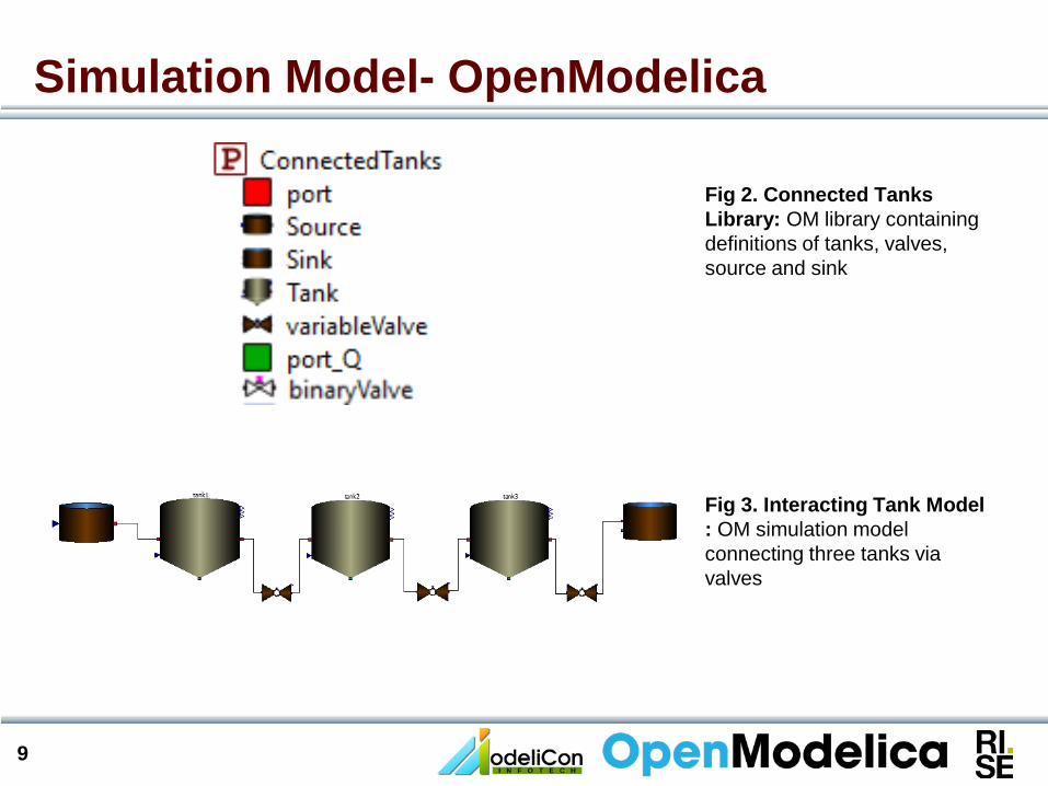
Fig 2. Connected Tanks Library: OM library containing definitions of tanks, valves, source and sink
Fig 3. Interacting Tank Model : OM simulation model connecting three tanks via valves
10
VR Model – Line Diagram
Fig 4. VR Model – Line Diagram
11
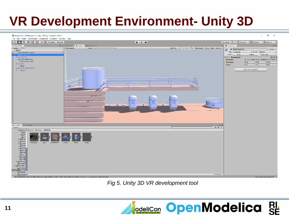
VR Development Environment- Unity 3D
Fig 5. Unity 3D VR development tool
12
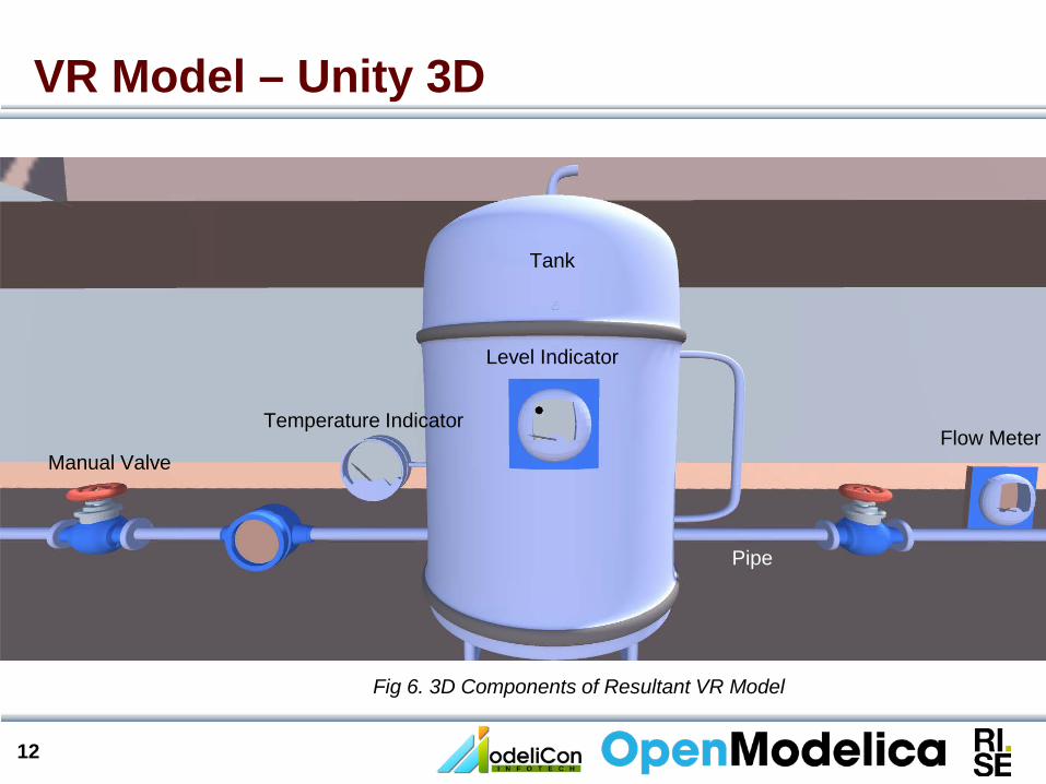
VR Model – Unity 3D
Manual Valve
Level Indicator
Temperature IndicatorFlow Meter
Tank
Pipe
Fig 6. 3D Components of Resultant VR Model
13
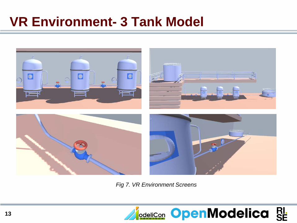
VR Environment- 3 Tank Model
Fig 7. VR Environment Screens

14
CodeSys PLC & HMI: 3 Tank Model
Fig 8. HMI screen in CodeSys
3. System Architecture
16
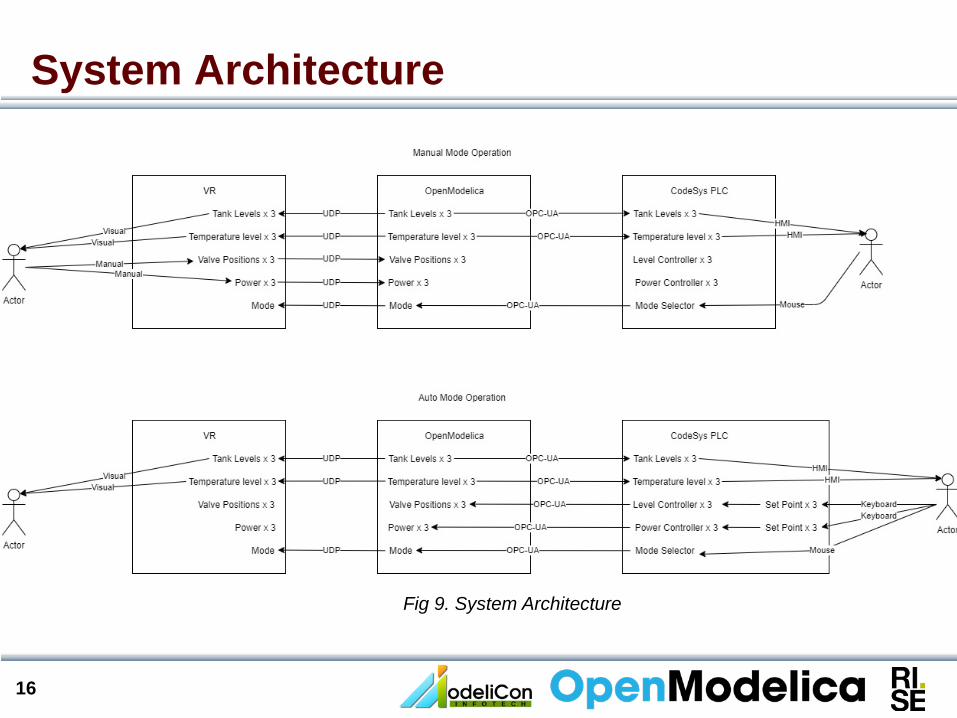
System Architecture
Fig 9. System Architecture
17
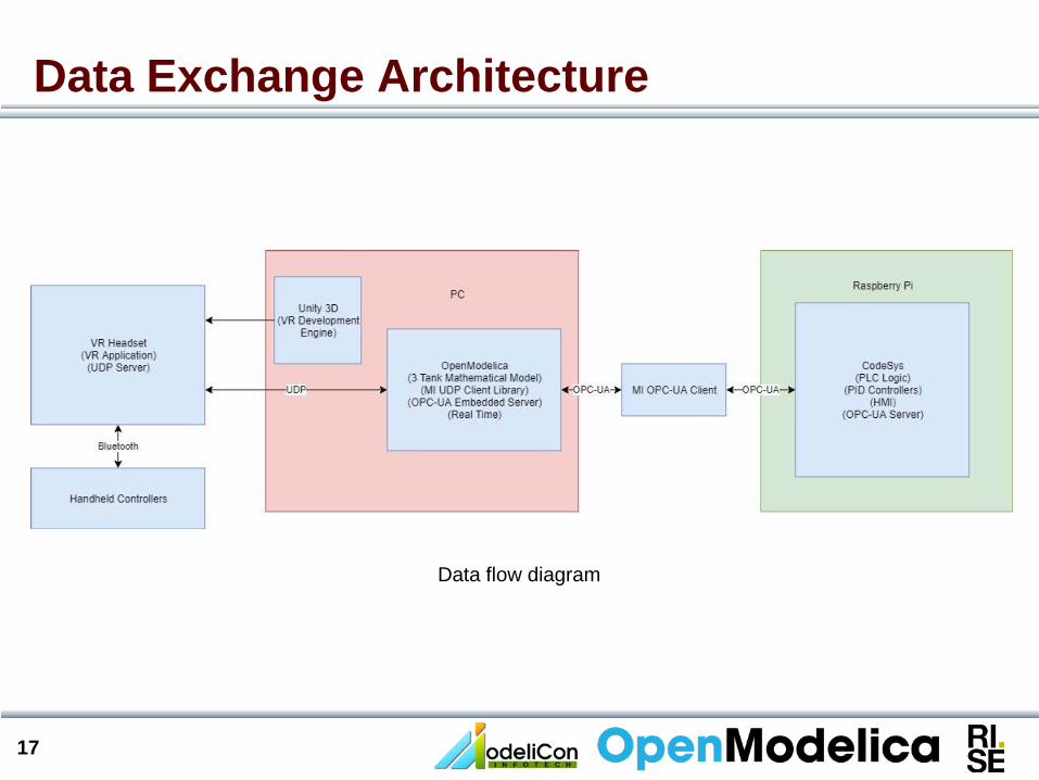
Data Exchange Architecture
Data flow diagram

4. Demonstration

19
One Tank Model- Demo
20
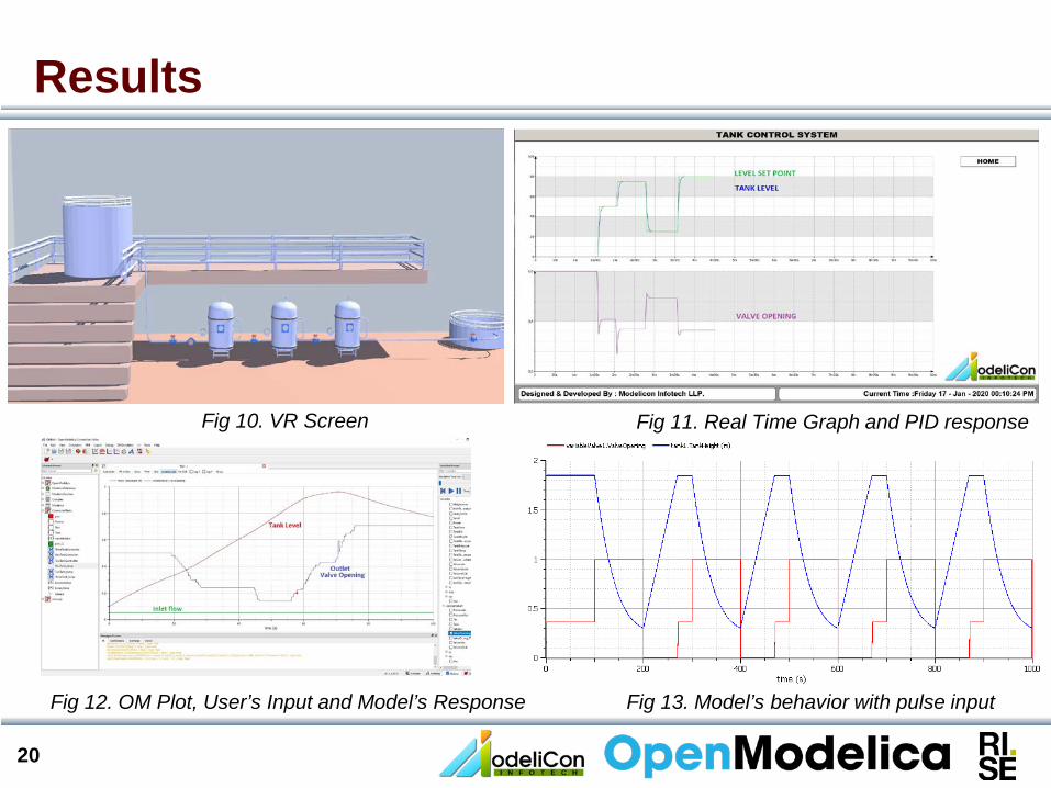
Results
Fig 10. VR Screen Fig 11. Real Time Graph and PID response
Fig 12. OM Plot, User’s Input and Model’s Response Fig 13. Model’s behavior with pulse input
21
Future Scope1. Development is being carried out in partnership with B.M.S. College of Engg.,
Bengaluru, India.
2. Two VR Models will be developeda. Interacting tanks modelb. Steam turbine model
3. Students will be able to carry out various experiments using those models.
4. Solution can serve a great purpose both in academia as well as industry.
Thank You