vikinginstallationguide - viking range
TRANSCRIPT

Viking Installation Guide
Designer DGVU Built-In Gas Cooktops
Viking Range Corporation
111 Front Street
Greenwood, Mississippi 38930 USA
(662) 455-1200
For product information,
call 1-888-VIKING1 (845-4641)
or visit the Viking Web site at
vikingrange.com
F20680B EN (020111)
®
09VK3130 ed.11-10
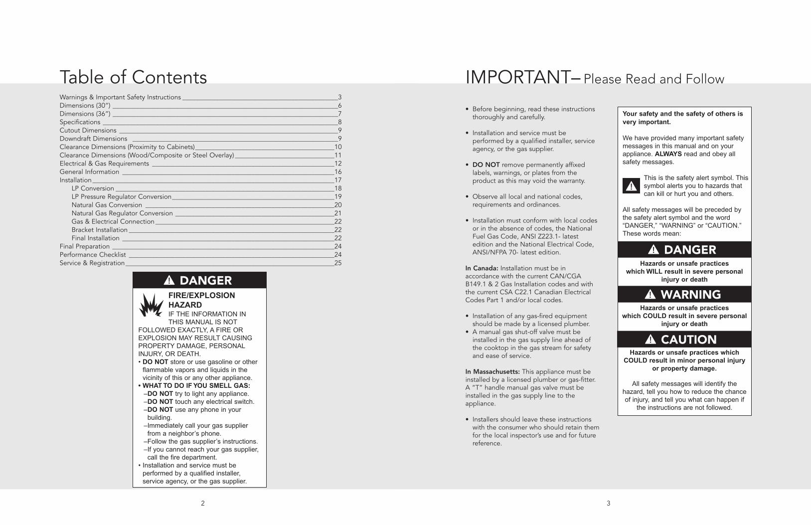
IMPORTANT• Before beginning, read these instructionsthoroughly and carefully.
• Installation and service must beperformed by a qualified installer, serviceagency, or the gas supplier.
• DO NOT remove permanently affixedlabels, warnings, or plates from theproduct as this may void the warranty.
• Observe all local and national codes,requirements and ordinances.
• Installation must conform with local codesor in the absence of codes, the NationalFuel Gas Code, ANSI Z223.1- latestedition and the National Electrical Code,ANSI/NFPA 70- latest edition.
In Canada: Installation must be inaccordance with the current CAN/CGAB149.1 & 2 Gas Installation codes and withthe current CSA C22.1 Canadian ElectricalCodes Part 1 and/or local codes.
• Installation of any gas-fired equipmentshould be made by a licensed plumber.
• A manual gas shut-off valve must beinstalled in the gas supply line ahead ofthe cooktop in the gas stream for safetyand ease of service.
In Massachusetts: This appliance must beinstalled by a licensed plumber or gas-fitter.A “T” handle manual gas valve must beinstalled in the gas supply line to theappliance.
• Installers should leave these instructionswith the consumer who should retain themfor the local inspector’s use and for futurereference.
3
– Please Read and Follow
Your safety and the safety of others isvery important.
We have provided many important safetymessages in this manual and on yourappliance. ALWAYS read and obey allsafety messages.
This is the safety alert symbol. Thissymbol alerts you to hazards thatcan kill or hurt you and others.
All safety messages will be preceded bythe safety alert symbol and the word“DANGER,” “WARNING” or “CAUTION.”These words mean:
Hazards or unsafe practiceswhichWILL result in severe personal
injury or death
DANGER
Hazards or unsafe practiceswhich COULD result in severe personal
injury or death
Hazards or unsafe practices whichCOULD result in minor personal injury
or property damage.
All safety messages will identify thehazard, tell you how to reduce the chanceof injury, and tell you what can happen if
the instructions are not followed.
WARNING
CAUTION
Table of ContentsWarnings & Important Safety Instructions _______________________________________________3Dimensions (30”) ____________________________________________________________________6Dimensions (36”) ____________________________________________________________________7Specifications _______________________________________________________________________8Cutout Dimensions __________________________________________________________________9Downdraft Dimensions ______________________________________________________________9Clearance Dimensions (Proximity to Cabinets)__________________________________________10Clearance Dimensions (Wood/Composite or Steel Overlay) ______________________________11Electrical & Gas Requirements _______________________________________________________12General Information ________________________________________________________________16Installation_________________________________________________________________________17
LP Conversion __________________________________________________________________18LP Pressure Regulator Conversion_________________________________________________19Natural Gas Conversion _________________________________________________________20Natural Gas Regulator Conversion ________________________________________________21Gas & Electrical Connection______________________________________________________22Bracket Installation ______________________________________________________________22Final Installation ________________________________________________________________22
Final Preparation ___________________________________________________________________24Performance Checklist ______________________________________________________________24Service & Registration_______________________________________________________________25
2
FIRE/EXPLOSIONHAZARDIF THE INFORMATION INTHIS MANUAL IS NOT
FOLLOWED EXACTLY, A FIRE OREXPLOSION MAY RESULT CAUSINGPROPERTY DAMAGE, PERSONALINJURY, OR DEATH.• DO NOT store or use gasoline or otherflammable vapors and liquids in thevicinity of this or any other appliance.
• WHAT TO DO IF YOU SMELL GAS:–DO NOT try to light any appliance.–DO NOT touch any electrical switch.–DO NOT use any phone in yourbuilding.–Immediately call your gas supplierfrom a neighbor’s phone.–Follow the gas supplier’s instructions.–If you cannot reach your gas supplier,call the fire department.
• Installation and service must beperformed by a qualified installer,service agency, or the gas supplier.
DANGER
IMPORTANT
5
– Please Read and FollowIMPORTANT
4
– Please Read and Follow
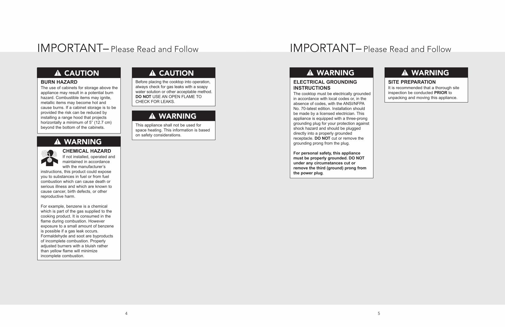
CHEMICAL HAZARDIf not installed, operated andmaintained in accordancewith the manufacturer’s
instructions, this product could exposeyou to substances in fuel or from fuelcombustion which can cause death orserious illness and which are known tocause cancer, birth defects, or otherreproductive harm.
For example, benzene is a chemicalwhich is part of the gas supplied to thecooking product. It is consumed in theflame during combustion. Howeverexposure to a small amount of benzeneis possible if a gas leak occurs.Formaldehyde and soot are byproductsof incomplete combustion. Properlyadjusted burners with a bluish ratherthan yellow flame will minimizeincomplete combustion.
WARNING
ELECTRICAL GROUNDINGINSTRUCTIONSThe cooktop must be electrically groundedin accordance with local codes or, in theabsence of codes, with the ANSI/NFPANo. 70-latest edition. Installation shouldbe made by a licensed electrician. Thisappliance is equipped with a three-pronggrounding plug for your protection againstshock hazard and should be pluggeddirectly into a properly groundedreceptacle. DO NOT cut or remove thegrounding prong from the plug.
For personal safety, this appliancemust be properly grounded. DO NOTunder any circumstances cut orremove the third (ground) prong fromthe power plug.
WARNINGBURN HAZARDThe use of cabinets for storage above theappliance may result in a potential burnhazard. Combustible items may ignite,metallic items may become hot andcause burns. If a cabinet storage is to beprovided the risk can be reduced byinstalling a range hood that projectshorizontally a minimum of 5” (12.7 cm)beyond the bottom of the cabinets.
CAUTIONBefore placing the cooktop into operation,always check for gas leaks with a soapywater solution or other acceptable method.DO NOT USE AN OPEN FLAME TOCHECK FOR LEAKS.
CAUTION
This appliance shall not be used forspace heating. This information is basedon safety considerations.
WARNING
SITE PREPARATIONIt is recommended that a thorough siteinspection be conducted PRIOR tounpacking and moving this appliance.
WARNING

Dimensions
7
36-3/4”(93.3 cm)
21”(53.4 cm)
34-1/8”(86.6 cm)
18-1/4”(47.0 cm)
10-3/16”(27.1 cm)
2”(5.1 cm)
2”(5.1 cm)
4”(10.2 cm)
2-13/16”(7.1 cm)
Wiring diagramand rating
plate location
Powercord Regulator
7-3/16”(18.3 cm)
36” Gas Cooktop
Dimensions
6
30-3/4”(78.2 cm)
21”(53.4 cm)
28-1/8”(71.4 cm)
18-1/4”(47.0 cm)
10-3/16”(27.1 cm)
2”(5.1 cm)
2”(5.1 cm)
4”(10.2 cm)
2-13/16”(7.1 cm)
Wiring diagramand rating
plate location
Powercord Regulator
7-3/16”(18.4 cm)
30” Gas Cooktop

9
C
B
A
Note: Based on 24” deep cabinet with 3/4” backsplash.
DGVU200 DGVU260
A 28-1/2” (72.4 cm) min. to29” (73.6 cm) max.
34-1/2” (87.6 cm) min. to35” (88.9 cm) max.
B 19” (48.3 cm) min. to19-5/8” (49.8 cm)
C 1-1/2” (3.8 cm)
Specifications
8
Designer Gas CooktopsDescription DGVU200 DGVU260
Overall width 30-3/4” (78.1 cm) 36-3/4” (93.3 cm)
Overall height from bottomto top of grate
4” (10.2 cm)
Overall depth from rear 21” (53.3 cm)
Cutout width 28-1/2” (72.4 cm) min. to29” (73.6 cm) max.
34-1/2” (87.6 cm) min. to35” (88.9 cm) max.
Cutout height 2-13/16” (7.1 cm)
Cutout depth 19” (48.3 cm) min. to19-5/8” (49.8 cm)
Gas requirements Accepts standard residential ½” (1.3 cm) I. D. gas service line.Shipped natural; gas regulator and orifice spuds are supplied with the product.To field convert from natural or LP/Propane, the orifice spuds and regulator
must be physically changed.
Electrical requirements 120 VAC/60 Hz; 4 ft. (121.9 cm), 3-wire cord with grounded3-prong plug attached to product.
Maximum amp usage 2.0 amps
Surface element ratingLeft front
Left rear
Center front/rear
Right front
Right rear
15,000 Nat./LP (BTU)(4.4 Nat./LP (kw))
4,000 Nat./LP (BTU)(1.0 Nat./LP (kw))
N/A
9,000 Nat./LP (BTU)(2.6 Nat./LP (kw))
12,000 Nat./LP (BTU)(3.5 Nat./LP (kw))
15,000 Nat./LP (BTU)(4.4 Nat./LP (kw))
4,000 Nat./LP (BTU)(1.0 Nat./LP (kw))
9,000 Nat./LP (BTU)(2.6 Nat./LP (kw))
12,000 Nat./LP (BTU)(3.5 Nat./LP (kw))
12,000 Nat./LP (BTU)(3.5 Nat./LP (kw))
Approximateshipping weight
35 lb. (15.9 kg) 60 lb. (27.2 kg)C
E F
D
A
B
Note: Refer to the downdraft installation instructions.
Downdraft Dimensions
DGVU200 DGVU260
A 29-1/8” (74.0 cm) 34-7/8” (88.6 cm)
B 20-5/8” (52.3 cm)
C 27 (68.6 cm) 33” (84.0 cm)
D 2-1/4” (5.7 cm)
E 1-1/16” (1.1 cm) 15/16” (1.0 cm)
F 1-1/16” (1.1 cm) 15/16” (1.0 cm)
Cutout Dimensions

Clearance Dimensions (Proximity to Cabinets)
11
30” min.
(76.2 cm)
13” max.
(33.0 cm)
5” min.(12.7 cm)
18” min.
(45.7 cm)
1-1/2”(3.8 cm)36” min.
(91.4 cm)
Note: Dimensions shown are for use withcombustible surfaces unless otherwise stated.
Proximity to Side Cabinet Installation• The cooktop may be installed directly toexisting base cabinets.
• The cooktop CANNOT be installed directlyadjacent to sidewalls, tall cabinets, tallappliances, or other side vertical surfacesabove 36” (91.4 cm) high. There must be aminimum of 5” (12.7 cm) side clearance fromthe cooktop to such combustible surfacesabove the 36” (91.4 cm) counter height.
• Within the 5” (12.7 cm) side clearance tocombustible vertical surfaces above36” (91.4 cm), the maximum wall cabinetdepth must be 13” (33.0 cm) and wall cabinetswithin this 5” (12.7 cm) side clearance must be18” (45.7 cm) above the 36” (91.4 cm) highcountertop.
• Wall cabinet above the cooktop mustbe a minimum of 30” (76.2 cm) above thecooking surface for a full width of the cooktop.This minimum height requirement does notapply if a rangehood is installed over thecooking surface.
• A 120 volt wall receptacle should belocated approximately 6” (15.2 cm) belowthe countertop cutout and 12” (30.5 cm)from the right side of the cutout.
Minimum Clearances from AdjacentCombustible Construction• Wall cabinets directly above the product must beminimum 30” (76.2 cm) above the cookingsurface.
• Side 5” (12.7 cm)• Rear 1-1/2” (3.8 cm) min.• Within 5” (12.7 cm) side clearance. Wallcabinets no deeper than 13” (33.0 cm)
• Must be minimum 18” (45.7 cm) abovecountertop
10
66”min.(167.6 cm)to72”max.(182.9 cm)
66”min.(167.6 cm)to72”max.(182.9 cm)
24”
(61.0 cm)
or
27”
(38.6 cm)
30”
(76.2 cm)
6”
(15.2 cm)
Wood/Composite
or Steel Overlay
Wood/Composite
or Steel Overlay
30”min.(76.2 cm)to36”max.(91.4 cm)
30”min.(76.2 cm)to36”max.(91.4 cm)
Wall Installation
Island Installation
Clearance Dimensions (Wood/Composite or Steel Overlay)
The bottom of a standard hood should be30” (76.2 cm) min. to 36” (91.4 cm) max. abovethe countertop. This would typically result in thebottom of the hood being 66” (167.6 cm) to72” (182.9 cm) above the floor. These dimensionsprovide for safe and efficient operation of thehood. Refer to the rangehood installationinstructions for additional information.

Electrical & Gas Requirements
Electrical RequirementsThere is no connection necessary beyondplugging the unit into a polarized, grounded,120 volt, 60 Hz, 15 amp circuit. A minimum of120 VAC is required for proper operation of gasignition systems. DO NOT use a GFI circuit.This circuit, however, MUST be grounded andproperly polarized. The unit is equipped with16-3 SPT2 power cord.
Note: If electrical power is not supplied or isinterrupted, the open top burners will have to belit manually with a match.
Gas Connection• Thread the appliances pressure regulator with1/2” male end connection both supplied withthis appliance.
• Make the gas connection to the inlet of thepressure regulator with 1/2” male pipe threads.
• Join the pressure regulator to the entrancethreads of the Gas Manifold with gasketsupplied with this appliance. The regulator ismarked with a directional arrow indicatingcorrect direction of gas flow. Ensure theappliance regulator is installed with the arrowpointing toward the gas manifold entrance andmake sure the top of the regulator is facingtowards the cabinet front, easily accessiblethrough the cabinet doors.
• Install a coupling between the regulator andthe shutoff valve to complete the connection.
• Assure all pipe joint connections are gas tight.• Check alignment of valves after connecting thecooktop to the gas supply to be sure themanifold pipe has not been moved. Amisalignment could cause the valve knob stemto rub on the control panel, resulting in a gasleak at the valve.
If an oven is to be installed below this appliance,connect gas supply line as shown in Figure 1.Consider the below cabinet clearance.
Manual shut-off valve:• The supplied valve must be installed in thegas service line ahead of the appliance andregulator in the gas stream. It should bepositioned where it can be reached quickly inthe event of an emergency.
In Massachusetts: A “T” handle type manualgas valve must be installed in gas supply line tothe appliance.
Pressure regulator:• The regulator supplied with the DGVUcooktops must be installed before any gasconnections are made. It is pre-set for use withnatural gas. This must be converted to use withLP/Propane gas.
• Manifold pressure should be checked with amanometer. Natural gas requires 5.0” WCPand LP/Propane requires 10.0” WCP. Incomingline pressure upstream for the regulator mustbe 1” WCP higher than the manifold pressurein order to check the regulator.
• The regulator used on this cooktop canwithstand a maximum input pressure of 1/2 PSI(14.0” WCP). If the line pressure is in excess ofthat amount, a step down regulator will berequired.
• The manual shut off valve and pressureregulator on these cooktops must bedisconnected from the gas supply pipingsystem during any pressure testing of thatsystem at pressures in excess of 1/2 PSI(3.45kPa.)
• The cooktop must be isolated from the gassupply piping system by closing its individualmanual shut-off valve during any pressuretesting of the gas supply piping system at testpressures equal to or less than 1/2 PSI(3.45kPa).
IMPORTANT: NEVER reuse old connectorswhen installing this cooktop.
1312
Rigid Connections:• Incoming gas is brought from an intake pipe atthe rear of the unit to the pressure regulator;then to the manifold pipe for distribution. Theintake pipe and shut-off valve are not supplied.The intake pipe and the shut-off valve shouldbe connected to the regulator to complete theconnection.
In Massachusetts: This appliance must beinstalled with a 36” (3-foot) long flexible gasconnector.
• Installer-supplied intake pipes should bechecked visually for any foreign matter beforeinstalling in a service line.
Before placing the cooktop into operation,always check for gas leaks with a soapywater solution or other acceptable method.DO NOT USE AN OPEN FLAME TOCHECK FOR LEAKS.
CAUTION
Electrical & Gas Requirements
012
Figure 2
011
ILLUSTRATIVE GAS SUPPLY PIPING(NO OTHER APPLIANCE BELOWCOOKTOP)
BURNER BOX(REAR OF APPLIANCE)
GASKET
GAS
FLARE UNIONADAPTOR
APPLIANCEPRESSURE
REGULATOR
ALL PIPE JOINTS1/2” N.P.T
MANIFOLDSHUTOFF
VALVES
Figure 1
90°STREETELBOW
CABINET SIDES CABINET SIDES
4-25/32”(12.2 cm)
HOLE DIAMETER1-1/5” (3.0 cm)

1514
Electrical & Gas Requirements Electrical & Gas Requirements
LP/Propane Conversion
The DGVU cooktops are shipped natural gas,and manufactured for use with natural gas orLP/Propane gas. Check the rating plate locatedon the bottom of the burner box for type ofgas needed.• To convert to natural gas or LP/Propane gas,the orifice spuds must be physically changedand the regulator must be reset. Gasconversions must be completed by a qualifiedservice technician.
• The installer must use a flexible connector of atleast ½” I.D. (1.3 cm) NPT and comply withANSI Z21.41 and Z21.69 standards.
To convert from both natural to LP/Propane andLP/Propane to natural a conversion kit issupplied.
Initial Ignition of Burners• All cooktops are tested before leaving thefactory. Field adjustments may be necessary forproper mixture of gas and air for properoperation. Contact a qualified technician tomake any necessary adjustments.
• The surface burners use electric igniters inplace of standing pilots.
Conversion must be performed by aqualified installer, service agency, or thegas supplier in accordance with themanufacturer’s instructions. Failure tofollow instructions could result in seriousinjury or property damage.
WARNING
Electrical power and gas must be turnedoff prior to conversion.
WARNING
Proper Lighting and Shutdown InstructionsTo ignite electric igniters on the surface burners:
1. Turn the knob counterclockwise to anyposition.
2. Upon ignition of the surface burner, turn theknob to the desired position (HI, Med or Low).
3. To shutdown the burner, turn knob clockwiseto the OFF position.
In case of failure, shut the gas OFF using theinstaller supplied manual shut-off valve.
Low Flame Adjustment
Note: If the burner does not light within fiveseconds, turn the knob off and wait oneminute before trying again.
This appliance is shipped from the factory withlow and medium flame settings adjusted.
Low Flame Adjustment (cont.)If further adjustment is necessary, proceed asfollows:
Adjustment for Burners1. Light burner and set control knob for lowflame.
2. Remove control knob from valve stem.3. Using a flathead screwdriver, adjust thescrew to set flame size:• clockwise to reduce• counterclockwise to increase
4. Replace control knob when adjustment iscompleted.
Proper adjustment will produce a stable,steady blue flame of minimum size. The finaladjustment should be checked by turningknob from high to low several times withoutextinguishing the flame.
ALow flame adjustment
This adjustment, at low setting, willautomatically provide the proper flame sizeat medium setting. After conversion stepshave been completed, check the appearanceof each burner's flame at the HI and LOsettings. If the flames appear too large or toosmall, review each step to make sure it wascompleted correctly.
Burner FlamesTurn each burner on. Flames should be bluein color with no trace of yellow. The burnerflames should not flutter or blow away fromthe burner. The inner cone of the flameshould be between 1/2" and 3/4" long.
COOKTOPBURNER
-1/2” to 3/4”
Burner flames
If you attempt to measure the inner cone ofthe flame, please use caution.Burns could result.
WARNING
Lighting gas burners with a match isdangerous.You should match light thecooktop burners only in an emergency.Light a match and hold the flame near theburner you want to light. Wooden matcheswork best. Push in and turn the controlknob slowly. Be sure you are turning thecorrect knob for the burner you are lighting.
DANGER
NOTE: To obtain the correct minimum settingwith LP gas, turn clockwise tightening the valveby the thin-blade screwdriver into the recess atcenter of valve stem.

General Information
Electrical Requirement• A standard 120V/60 Hz, 15 amp circuit,3-wire ground, 3-prong plug is equipped.
• A minimum of 120 VAC is required for properoperation of gas ignition systems. The circuitmust be MUST be properly grounded andpolarized.
IMPORTANT: It is recommended to have theelectrical wiring and installation of yourcooktop connected by a qualified electrician.
IMPORTANT: The cooktop must be electricallygrounded in accordance with local codes or, inthe absence of local codes, with the NationalElectrical Code, ANSI/NFPA 70 latest edition orCanadian Electrical Code (CSA).
Surface BurnersInitial Ignition of Burners• All cooktops are tested before leaving thefactory. Field adjustments may be necessaryfor proper mixture of gas and air for properoperation. Contact a qualified technician tomake any necessary adjustments.
• The surface burners use electric igniters inplace of standing pilots.
To ignite electric igniters on the surface burners:• Turn the knob counterclockwise to anyposition.
• Upon ignition of the surface burner, turn theknob to the desired position (HI, Med or Low).
• To shutdown the burner, turn knob clockwiseto the OFF position.
• In case of failure, shut the gas OFF using theinstaller supplied manual shut-off valve.
Site PreparationNote: It is recommended that a thorough siteinspection be conducted prior to unpacking andmoving this appliance.
• Confirm available access to adequate power–see electrical requirements.
• Be sure that the countertop for this applianceis level and cut according to the cutoutrequirements and dimensions–see cutoutrequirements and dimensions.
• All wall coverings, countertop and cabinetsaround the cooktop should withstand heat upto 200°F (90°C).
• Keep appliance free from combustiblematerials, gasoline, and other flammablevapors.
Installation ProcedureRemove packaging materials and literaturepackage from the cooktop before beginninginstallation. Remove Installation Instructionsfrom literature pack and read them carefullybefore you begin.
17
ELECTRICAL SHOCKHAZARDPlug into a 3 prong outlet.DO NOT remove ground prong.
DO NOT use an adapter.DO NOT use an extension cord.Failure to follow these instructions canresult in death, fire, or electrical shock.
CAUTION
DO NOT use an extension cord with thisappliance. Such use may result in fire,electrical shock or other personal injury
WARNING
16
2
1
12
2
2
1 2
Remove the grates and burner caps. Turn the cooktop upside down and place on thepackaged foam top. Note: Make sure there are no looseobjects on the cooktop before turning upside down.
3 Optional Gasket 4
Installation
Peel away the plastic covering and place the gasketmaterial all the way around the burner flange.
IMPORTANT: Make sure the corners are coveredcompletely, leaving no air gaps.
Turn the cooktop over and place intocountertop opening.

1918
LP Conversion
3 60 105
105
90
105
90115
60
115
4
1
1
1
1
2
Reference chart to determine which injectors areneeded for each burner.
Install and tighten injectors.
5
Replace aluminum flame spreaders.
1
Remove aluminum gas spreaders. Unscrew regulator cap.
LP Pressure Regulator Conversion
4
2
1
Replace regulator cap.
5
Test gas pressure. When converting the regulator for differentsettings, the function of the regulator must be checked at a pressure at
least 1” WC (249Pa) above the specified manifold pressure.
2
1
2
Disconnect electrical power and shut off gas.
1
2
2
2
2
2
1
Remove injectors using a 9/32” nut driver.
3
1 5
2 4
3
Unscrew the plastic conversion plug from the capand turn over. Screw plug back into cap with the wide
section away from cap.
LP conversion should only be performedby a qualified service technician
WARNING

2120
Natural Gas Conversion Natural Gas Regulator Conversion
3 95 160
160
139
160
139180
95
180
4
1
1
1
1
2
Reference chart to determine which injectors areneeded for each burner.
Install and tighten injectors.
5
Replace aluminum flame spreaders.
1
Remove aluminum gas spreaders.
2
2
2
2
2
1
Remove injectors using a 9/32” nut driver.
Natural conversion should only beperformed by a qualified service technician.
WARNING
Unscrew regulator cap.
4
2
1
Replace regulator cap.
5
Test gas pressure. When converting the regulator for differentsettings, the function of the regulator must be checked at a pressure at
least 1” WC (249Pa) above the specified manifold pressure.
2
1
2
Disconnect electrical power and shut off gas.
1
3
1 5
2 4
3
Unscrew the plastic conversion plug from the capand turn over. Screw plug back into cap with the wide
section close to the cap.
Note: After injectors replacement,adjust the burner flame (See LowFlame Adjustment in Electrical &Gas Requirements section).

2322
Place brackets in the slots and lower until thebracket catches. Use the bolt to tighten the cooktopto the countertop. Note: There must be a 1” (2.5 cm)clearance under counter on all four sides of cooktop.
Note: If cabinet construction does not provideenough clearance for installing brackets on the frontand back of the burner box, install the brackets on
the sides of burner box.
Final Installation
Note: Refer to“Electrical & GasRequirements”
section forproper
installationinformation.
1
Gas & Electrical Connection
Cooktop
Bracket
Countertop
1
Bracket Installation
1
2
2
11
1
1
Replace the burner caps and grates.Note: The narrow edge of grate goes toward center of unit.
Wiring Diagram(DGVU260)
1
2
3
4
5
1
2
3
4
5
Brown
White
Red
Blue
Gray
Brown
White
Red
Gray
WhiteBlue
White
Red
TerminalBlock
WhiteRed
Green
Black
White
G N L
G N L
RE-IGNITERSYSTEM
1234
56
SW 1SW 2SW 3SW 4SW 5SW 6
Wiring Diagram(DGVU200)
BrownBrown
White
Red
Blue
White
Red
BlueWhite
WhiteRed
Green
TerminalBlock
White
Red
G N L
G N LBlack
White
RE-IGNITERSYSTEM
1
1
2
3
4
1
2
3
4
234
SW 1SW 2SW 3SW 4
Wiring Diagrams

2524
Service & RegistrationOnly authorized replacement parts may be used in performing service on the appliance.All servicing should be referred to a qualified technician.
Contact Viking Range Corporation, 1-888-VIKING1 (845-4641), for the nearest service partsdistributor in your area or write to:
VIKING RANGE CORPORATIONPREFERRED SERVICE
1803 Hwy 82WGreenwood, Mississippi 38930 USA
The serial number and model number for your appliance can be found by looking under thecooktop.
Record the following information indicated below. You will need it if service is ever required.
Model number ____________________________________________________________________________________
Serial number _____________________________________________________________________________________
Date of purchase __________________________________________________________________________________
Date installed ______________________________________________________________________________________
Dealer's name _____________________________________________________________________________________
Address ___________________________________________________________________________________________
These installation instructions should remain with the unitfor future reference.
• New units are cleaned at the factory to removeany visible signs of dirt, oil, grease, etc.remaining from the manufacturing process.Some stainless steel parts may have a plasticprotective wrapper which must be peeled off.The cooktop should be washed thoroughlywith hot, soapy water and then rinsed andwiped dry to remove these film residues andany installation dust or debris before beingused for food preparation.
• All stainless steel body parts should be wipedregularly with hot, soapy water and with aliquid cleanser designed for this material ifbuild-up occurs. DO NOT use steel wool,abrasive cloths, cleansers, or powders. If it isnecessary to scrape stainless steel to removeencrusted material, soak with hot, wet cloths toloosen the material, then use a wood or nylonscraper. DO NOT use a metal knife, spatula, orany other metal tool to scrape stainless steel.Scratches are almost impossible to remove.
A qualified installer should carry out the followingchecks:
h Check top burnerignition. The lowflame should light atevery port.
h Starting with the leftfront burner, turn thecorresponding knob to the HI position–seedrawing for proper flame height.
h Repeat steps for other burners.
1-1/2”(3.8 cm)
3/8”(0.95 cm)
Performance Checklist
Final Preparation

27
Notes________________________________________________________________________________________________________________________________________________________
________________________________________________________________________________________________________________________________________________________
________________________________________________________________________________________________________________________________________________________
________________________________________________________________________________________________________________________________________________________
________________________________________________________________________________________________________________________________________________________
________________________________________________________________________________________________________________________________________________________
________________________________________________________________________________________________________________________________________________________
________________________________________________________________________________________________________________________________________________________
________________________________________________________________________________________________________________________________________________________
________________________________________________________________________________________________________________________________________________________
________________________________________________________________________________________________________________________________________________________
________________________________________________________________________________________________________________________________________________________
________________________________________________________________________________________________________________________________________________________
________________________________________________________________________________________________________________________________________________________
________________________________________________________________________________________________________________________________________________________
________________________________________________________________________________________________________________________________________________________
________________________________________________________________________________________________________________________________________________________
________________________________________________________________________________________________________________________________________________________
________________________________________________________________________________________________________________________________________________________
________________________________________________________________________________________________________________________________________________________
________________________________________________________________________________________________________________________________________________________
________________________________________________________________________________________________________________________________________________________
26
Notes________________________________________________________________________________________________________________________________________________________
________________________________________________________________________________________________________________________________________________________
________________________________________________________________________________________________________________________________________________________
________________________________________________________________________________________________________________________________________________________
________________________________________________________________________________________________________________________________________________________
________________________________________________________________________________________________________________________________________________________
________________________________________________________________________________________________________________________________________________________
________________________________________________________________________________________________________________________________________________________
________________________________________________________________________________________________________________________________________________________
________________________________________________________________________________________________________________________________________________________
________________________________________________________________________________________________________________________________________________________
________________________________________________________________________________________________________________________________________________________
________________________________________________________________________________________________________________________________________________________
________________________________________________________________________________________________________________________________________________________
________________________________________________________________________________________________________________________________________________________
________________________________________________________________________________________________________________________________________________________
________________________________________________________________________________________________________________________________________________________
________________________________________________________________________________________________________________________________________________________
________________________________________________________________________________________________________________________________________________________
________________________________________________________________________________________________________________________________________________________
________________________________________________________________________________________________________________________________________________________
________________________________________________________________________________________________________________________________________________________