mewtocoldownload.gongkong.com/file/2005/4/23/mewtocol.doc · web viewword numeric values are...
TRANSCRIPT


Computer Link
计算机链接MEWTOCOL-COM
特点1.用于程序处理和交互式操作.
2.数据传输采用ASCII码的形式.
3.首先由计算机发送指令.
4.由 PLC对指令自动进行相应响应.
基本描述指令格式
指令信息:
%AD(H)
AD(L)
# 指令代码 文本代码1
BCC(H)
BCC(L)
CR
应答信息 (正常时):
%AD(H)
AD(L)
$ 响应代码 文本代码1
BCC(H)
BCC(L)
CR
校验数据范围

应答信息 (发生错误时):
%AD(H)
AD(L)
! 错误代码(H)
错误代码(L)
BCC(H)
BCC(L)
CR

指令一览表
指令 功能描述RCS Read single point of contact information 读取单个触点的状态信息WCS Write single point of contact information 写入单个触点的状态信息RCP Read plural point of contact information 读取多个触点的状态信息WCP Write plural point of contact information 写入多个触点的状态信息RCC Read word unit of contact information 读取字单位的触点的状态信息WCC Write word unit of contact information 写入字单位的触点的状态信息SC Preset word unit in contact area 预置字单位的触点RD Read data area 读取数据寄存器值WD Write data area 写入数据寄存器值SD Preset of data area 预置数据寄存器值RS Read timer and counter set value area 读取定时器/计数器目标值WS Write timer and counter set value area 写入定时器/计数器目标值RK Read timer and counter elapsed value area 读取定时器/计数器经过值WK Write timer and counter elapsed value area 写入定时器/计数器经过值MC Registration and reset of monitor contact 登录及复位监控触点MD Registration and reset of monitor data 登录及位监控数据MG Monitor execution 执行监控RR Read system register 读取系统寄存器WR Write system register 写入系统寄存器RT Read Programmable Controller (PC) status 读取 PLC当前状态RP Read program 读取程序WP Write program 写入程序RM Remote control (RUN/PROGRAM mode switching) 远程控制(运行/编程模式切换)
AB Transmission abort command 传输终止指令

触点和数据代码
1. 触点代码
触点代码 说明X 外部输入Y 外部输出R 内部继电器T 定时器C 计数器L 链接继电器
2. 数据代码
数据代码 说明D 数据寄存器 DT
L 链接寄存器 LD
F 文件寄存器 FL
S 目标值 SV
K 经过值 EV

IX 索引寄存器 IX
IY 索引寄存器 IY
WX 字单位外部输入 WX
WY 字单位外部输出 WY
WR 字单位内部继电器 WR
WL 字单位链接继电器 WL

错误代码
错误类型 代码 说明
链接系统错误20
21
22
23
24
25
26
27
28
29
30
未定义:
NACK 错误:
WACK 错误:
多重端口错误:
传输格式错误:
硬件错误:
单元号错误:
不支持错误:
无应答错误:
缓冲区关闭错误:
超时错误:
远程单元无法被正确识别,或者发生了数据错误.
用于远程单元的接收缓冲区已满.
远程单元编号(01至 16)设置与本地单元重复.
试图发送不符合传输格式的数据. 或者某一帧数据溢出或发生了数据错误.
传输系统硬件停止操作.
远程单元的编号设置超出 01至 63的范围.
接收方数据帧溢出. 试图在不同的模块之间发送不同帧长度的数据.
远程单元不存在. (超时)
试图发送或接收处于关闭状态的缓冲区.
持续处于传输禁止状态.
基本程序错误40
41
42
43
BCC 错误:
格式错误:
不支持错误:
处理步骤错误:
在指令数据中发生传输错误.
所发送的指令信息不符合传输格式.例:
指令中的数据项目过多或不足.缺少"#"符号及"目标站号".
发送了一个未被支持的指令.向未被支持的目标站发送了指令.
在处于传输请求信息挂起时,发送了其他指令.

处理系统错误50
51
52
53
链接设置错误:
同时操作错误:
传输禁止错误:
忙错误:
设置了实际不存在的链接编号.
当向其他单元发出指令时,本地单元的传输缓冲区已满.
无法向其他单元传输.
在接收到指令时,正在处理其他指令.

错误类型 代码 说明
PLC错误60
61
62
63
65
66
67
参数错误:
数据错误:
Registration error:
PLC模式错误:
保护错误:
地址错误:
缺少数据错误:
在指令中包含有无法使用的代码,或者代码没有附带区域指定参数(X,Y,D,等以外.)指令中的代码带有非法的功能指定参数(0,1,2,等).
触点编号,区域编号,数据代码格式(BCD,hex,等.),上溢出, 下溢出以及区域指定错误.
Excessive number of registrations or operation in unregistered state.(monitor registration, trace registration, etc.)When a registration overflow occurs, perform a registration reset.
Operating mode of the PLC when a command was sent does not allow the command to be processed
Write operation was performed to the program area or system register in the memory protect states.
Address (program address, absolute address, etc.) data code format (BCD, hex, etc.), overflow, underflow or range specification error.
Read data does not exist. (Data not written with a comment registration was read.)

指令说明1.读取单触点状态(指令代码: RCS) Contact Area Read (single point)
指令% # R C S
触点代码(1字符)
触点编号(4字符)
BCC(H)
BCC(L)
CR
应答读取正常
% $ R C触点数据(1字符)
BCC(H)
BCC(L)
CR
读取错误% !
BCC(H)
BCC(L)
CR
说明: 字符"$"表示正常的应答.
触点数据 Contact data
触点状态 数据OFF "0"
ON "1"
目标站号(L)目标站号(H)
源站号(L)源站号(H)
源站号(L)源站号(H)
错误代码
参阅说明.
BCD HEX(3 digits) (1 digit)单触点指定

2. 写入单触点状态(指令代码: WCS ) Contact Area Write (single point)
指令% # W C S
指令代码(1字符)
触点编号(4字符)
触点数据(1字符)
BCC(H)
BCC(L)
CR
应答读取正常
% $ W CBCC(H)
BCC(L)
CR
读取错误% !
BCC(H)
BCC(L)
CR
说明: 字符"$"表示正常的应答.
触点数据 Contact data
触点状态 数据OFF "0"
ON "1"
目标站号(L)目标站号(H)
源站号(L)源站号(H)
源站号(L)源站号(H)
错误代码
BCD HEX(3 digits) (1 digit)单触点指定 参见注释.
Y, R, L

Contact No.(4 bytes)
3. Supplementary Description of Read/Write Contact Area
(Single point) [ Timer(T), Counter(C), Contract code ]
Even if a no. which is used internally as T(C) is read as C(T) no. it does not result in an error and the contact information for the no. returns.
(word unit block) RCC, WCC Timer and counter contacts are not handled id word units If a word no. is specified with the T or C contact code, the information shown below returns.
Contact Code Crowd No. Response information T(C) 0 T(C): 0 to 15
1 T(C): 16 to 312 T(C): 32 to 473 T(C): 48 to 63
: : : :
15 T(C):240 to 255
Contact No.(4 bytes)
BCD HEX(3 digits) (1 digit)
BCD 0 (3 digits)X,Y,R,L T, C

4. 读取多触点状态(指令代码: RCP ) Read Contract Area(plural point)
指令
% # R C Pn
(1字符)触点代码(1字符)
触点编号.(1)
(4字符)
触点代码(1字符)
触点编号.(n)
(4字符)
BCC(H)
BCC(L)
CR
应答读取正常
% $ R C触点 1数据
(1字符)
触点 n数据
(1字符)
BCC(H)
BCC(L)
CR
读取错误% !
BCC(H)
BCC(L)
CR
说明: 字符"$"表示正常应答.
触点数据触点状态 数据
目标站号(L)目标站号(H)
源地址(L)源地址(H)
错误代码
BCD HEX(3 digits) (1 digit)多触点指定
触点编号(n: 1 to 8 )
n=1 - 8
参见说明.
源地址(L)源地址(H)

OFF "0"
ON "1"

5. 写入多触点状态(指令代码: WCP )Write Contract Area (plural point)
指令%
# W C Pn
(1字符)
触点 1 代码
(1字符)
触点 1编号.(4字符)
触点数据(1字符)
触点 n 代码
(1字符)
触点 n编号.(4字符)
触点数据(1字符)
BCC(H)
BCC(L)
CR
应答读取正常
% $ W CBCC(H)
BCC(L)
CR
读取错误% !
BCC(H)
BCC(L)
CR
说明: 字符"$"表示正常应答.
触点数据触点状态 数据
OFF "0"
ON "1"
目标地址(L)目标地址(H)
源地址(L)源地址(H)
源地址(L)源地址(H)
错误代码
BCD HEX(3 digits) (1 digit)多触点指
定n: 1 to 8
Y, R, L
n=1 - 8


6. Contact Area Read (word unit block) (Command code: RCC )Command
%# R C C
Contact code
(1 character)
Startword No.
(4 characters)
Endword No.
(4 characters)
BCC(H)
BCC(L)
CR
Response
Read OK
%$ R C
Contact data1
(4 character)
Contact datan
(4 character)
BCC(H)
BCC(L)
CR
Read Error
% !BCC(H)
BCC(L)
CR
Note:
Contact codes are the same as for the read single point
Contact Data Sequence
Word F C B 8 7 4 3 0
③ ④ ① ②
Contact data
① ② ③ ④
Destination(L)Destination(H)
Source(L)Source(H)
Source(L)Source(H)
Error code
BCD Crowdhandling
BCD X, Y, R, L BCD
HEX
HEX

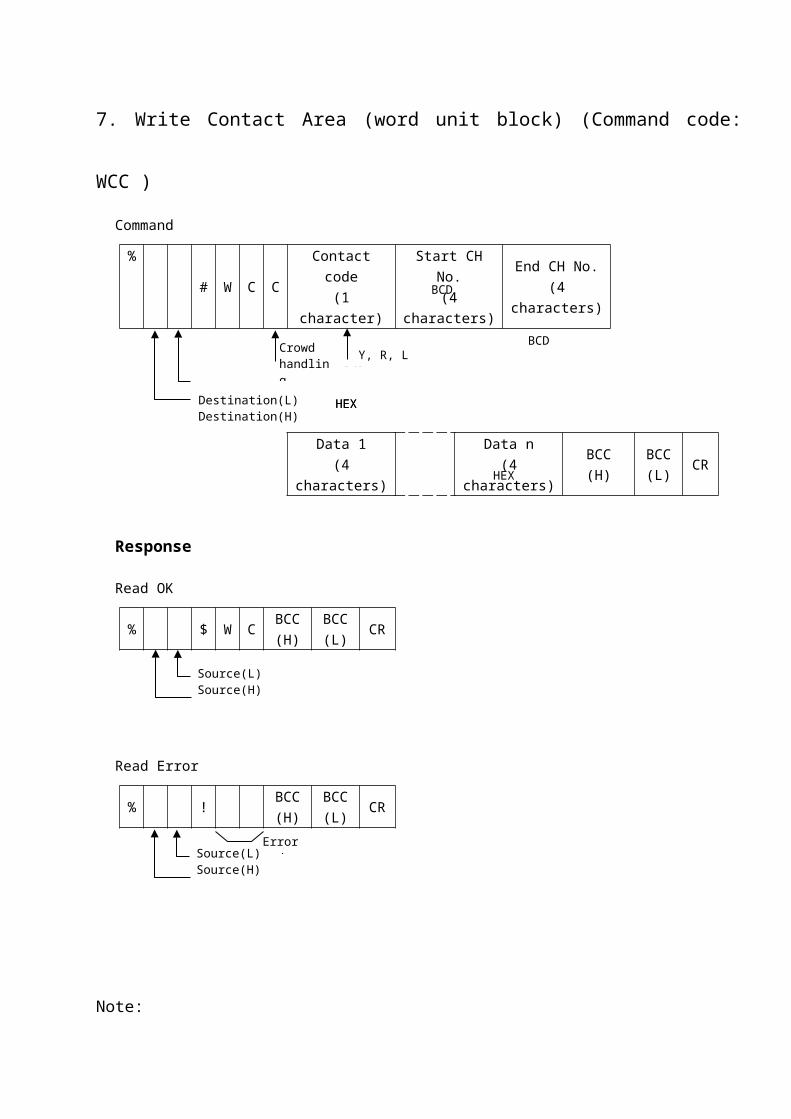
7. Write Contact Area (word unit block) (Command code: WCC )Command
%# W C C
Contact code(1 character)
Start CH No.(4 characters)
End CH No.(4 characters)
Data 1
(4 characters)Data n
(4 characters)BCC(H)
BCC(L)
CR
Response
Read OK
% $ W CBCC(H)
BCC(L)
CR
Read Error
% !BCC(H)
BCC(L)
CR
Note:
Contact codes are the same as for the read single point
Contact Data Sequence
Word F C B 8 7 4 3 0
③ ④ ① ②
Contact data
① ② ③ ④
Destination(L)Destination(H)
Source(L)Source(H)
Source(L)Source(H)
Error code
Crowdhandling
BCD Y, R, L BCD
BCD
HEX HEX HEX

8. Preset Word Unit in Contact Area (Command code: SC )Command
%# S C
Contact
code
(1 character)
Start word
No.
(4 characters)
End word
No.
(4 characters)
Word preset
pattern
(4 characters)
BCC
(H)
BCC
(L)CR
Response
Preset OK
% $ S CBCC(H)
BCC(L)
CR
Preset Error
% !BCC(H)
BCC(L)
CR
Destination(L)Destination(H)
Source(L)Source(H)
Source(L)Source(H)
Error code
BCD Y, R, L BCD
BCD
HEX

9. Read Data Area (Command code: RD )Command
%# R D
Data code(1 character)
Start data No.(5 characters)
End data No.(5 characters)
BCC(H)
BCC(L)
CR
Response
Read OK
%$ R D
Data 1(4 characters)
Data n(4 characters)
BCC(H)
BCC(L)
CR
Read Error
% !BCC(H)
BCC(L)
CR
Note:
Data (4 characters)
D③ ④ ① ②
F C
Data
① ② ③ ④
Destination(L)Destination(H)
Source(L)Source(H)
Source(L)Source(H)
Error code
D, L, F BCD
BCD BCD
HEX HEX

Details of a command and its response are illustrated in the example.
Reading from the Data Area (Read command)The contents of the Programmable Controller's(PLC's) data area are read by the host computer.
Program Example:The data contents in DT1105 to DT1107 of the Programmable Controller(PLC) are read.Assume that DT1105 to DT1107 contain the following numeric values.
DT1105 = 0063HDT1106 = 3344HDT1107 = 000AH
The command from the host computer is shown below.
% 01 # RD D 01105 01107 57 CR
Header Destination Command name DT1105 DT1107 BCC Terminator
The response from the Programmable Controller(PLC) is shown below
% 01 $ RD 6300 4433 0A00 62 CR
Header Destination Command name Data of Data of Data of BCC Terminator
DT1105 DT1106 DT1107
Note:
The "$" indicates a normal response.
For Index Register
Command
%# R D
Data code(1 character)
"0" (9 characters)BCC(H)
BCC(L)
CR
Response
Read OK (for IX, IY)
%$ R D
Data 1(4 characters)
BCC(H)
BCC(L)
CR
Read OK (for ID)
%$ R D
Data (IX)(4 characters)
Data (IY)(4 characters)
BCC(H)
BCC(L)
CR
Read Error
% !BCC(H)
BCC(L)
CR
Note:
Data Code
Data CodeIX "I" "X"IY "I" "Y"
IX, IY "I" "D"
Destination(L)Destination(H)
Source(L)Source(H)
Source(L)Source(H)
Error code
See note BCD
HEX HEX
Source(L)Source(H)
HEX (high order)
HEX (low order)

10. Write Data Area (Command code: WD )Command
%# W D
Data code(1 character)
Start data No.(5 characters)
End data No.(5 characters)
Write Data
(4 characters)Write Data
(4 characters)BCC(H)
BCC(L)
CR
Response
Write OK
% $ W DBCC(H)
BCC(L)
CR
Write Error
% !BCC(H)
BCC(L)
CR
Write to IX, IY (between WD and BCC)
Data code(2 characters)
"0" ( 9 characters)Write data
(4 characters)
Batch processing ( write to IX, IY 32-bit ) (between WD and BCC)
Data code(2 characters)
"0" ( 9 characters)Write data
(4 characters)Write data
(4 characters)
Destination(L)Destination(H)
Source(L)Source(H)
Source(L)Source(H)
Error code
BCD D, L, F
HEX
BCD
HEX HEX
HEX
DI I I
IX(low order) IY(high order)

Details of a command and its response are illustrated in the examples.
Writing to the Data Area (WD command)A numeric value is written to the Programmable Controller's(PLC's) data area by the host computer.
Program Example:Word numeric values are written to DT1 to DT3 of the Programmable Controller(PLC).The response from the Programmable Controller(PLC) is shown below.The contents of the Programmable Controller's(PLC's) data area are read by the host computer.
% 01 # WD D 00001 00003 0500 0715 0009 5D CR
Header Destination Command name From DT1 DT3 Data of Data of Data of BCC Terminator
DT1 DT2 DT3
The response from the Programmable Controller(PLC) is shown below. % 01 $ WD 13 CR
Header Destination Command name BCC Terminator
Note:
The "$" indicates a normal response.

11. Preset of Data Area (Command code: SD )Command
%# S D
Contact
code
(1 character)
Start data
No.
(5 characters)
End data
No.
(5 characters)
Word preset
pattern
(4 characters)
BCC
(H)
BCC
(L)CR
Response
Preset OK
% $ S DBCC(H)
BCC(L)
CR
Preset Error
% !BCC(H)
BCC(L)
CR
The same word (2-byte) data is written to the specified range of the data area or
link data area.
Destination(L)Destination(H)
Source(L)Source(H)
Source(L)Source(H)
Error code
BCD D, L, F
BCD
HEX

12. Read Set Value Area (Command code: RS )Command
%# R S
Start module No.
(4 characters)
End module No.
(4 characters)
BCC(H)
BCC(L)
CR
Response
Read OK
%$ R S
Data 1(4 characters)
Data n(4 characters)
BCC(H)
BCC(L)
CR
Read Error
% !BCC(H)
BCC(L)
CR
Note:
Data is handle in 16-bit.
The maximum number of specified modules is 24.
Destination(L)Destination(H)
Source(L)Source(H)
Source(L)Source(H)
Error code
HEX HEX
BCD BCD

13. Write Set Value Area (Command code: WS )Command
%# W S
Start module No.(4 characters)
End module No.(4 characters)
Data 1(4 characters)
Data n(4 characters)
BCC
(H)
BCC
(L)CR
Response
Write OK
%$ W S
BCC(H)
BCC(L)
CR
Write Error
% !BCC(H)
BCC(L)
CR
Destination(L)Destination(H)
Source(L)Source(H)
Source(L)Source(H)
Error code
BCD BCD
HEX HEX

14. Read Count (Elapsed) Value Area (Command code: RK )Command
%# R K
Start module No.
(4 characters)
End module No.
(4 characters)
BCC(H)
BCC(L)
CR
Response
Read OK
%$ R K
Data 1(4 characters)
Data n(4 characters)
BCC(H)
BCC(L)
CR
Read Error
% !BCC(H)
BCC(L)
CR
Note:
Data is handle in 16-bit.
The maximum number of specified modules is 24.
Destination(L)Destination(H)
Source(L)Source(H)
Source(L)Source(H)
Error code
HEX HEX
BCD BCD

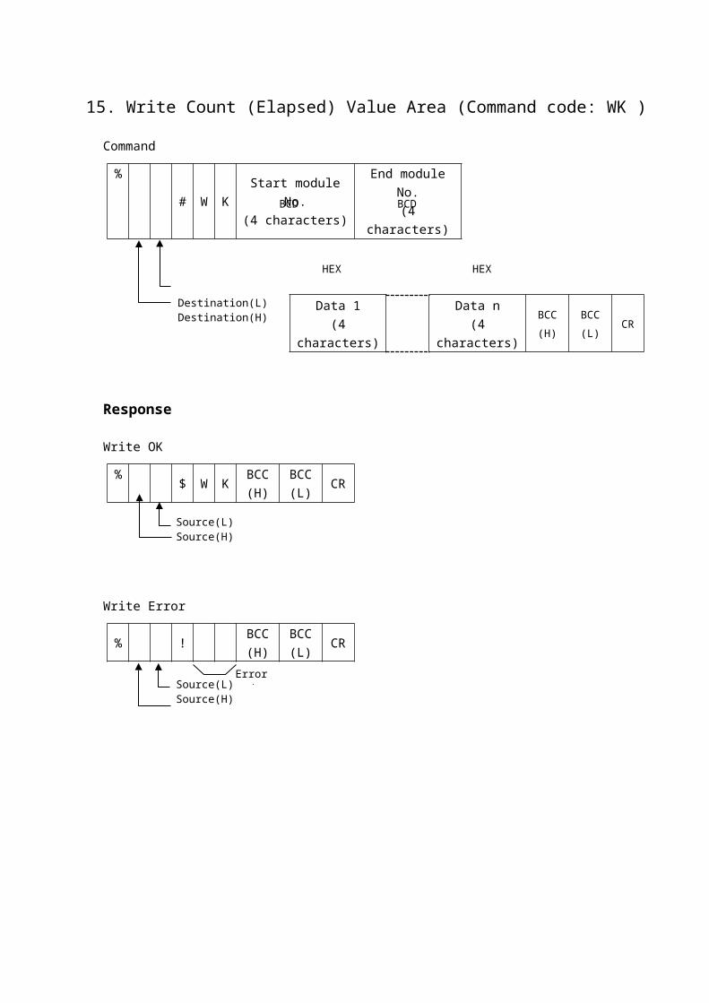
15. Write Count (Elapsed) Value Area (Command code: WK )Command
%# W K
Start module No.(4 characters)
End module No.(4 characters)
Data 1(4 characters)
Data n(4 characters)
BCC
(H)
BCC
(L)CR
Response
Write OK
%$ W K
BCC(H)
BCC(L)
CR
Write Error
% !BCC(H)
BCC(L)
CR
Destination(L)Destination(H)
Source(L)Source(H)
Source(L)Source(H)
Error code
BCD BCD
HEX HEX

16. Monitor Contact Registration and Reset (Command code: MC )
Command
(Registration)
% # M CContact code(1 character)
Contact No.(4 characters)
Contact code(1 character)
Contact No.(4 characters)
BCC
(H)
BCC
(L)CR
(Registration Reset)
% # M C F F F F FBCC
(H)
BCC
(L)CR
Response
Registration OK
%$ M C
BCC(H)
BCC(L)
CR
Registration Error
% !BCC(H)
BCC(L)
CR
Note:
If the contact code is "*", it is a dummy registration.
The maximum number of registrations per unit is 80 points.
(Up to 20 points per command.)
Destination(L)Destination(H)
Source(L)Source(H)
Source(L)Source(H)
Error code
BCD HEX(3 digits) (1 digit)X,Y,R,T,C,L
20 points max.
Destination(L)Destination(H)

17. Monitor Data Registration and Reset (Command code: MD )
Command
(Registration)
% # M DData code
(1 character)Data No.
(5 characters)
Data code(1 character)
Data No.(5 characters)
BCC
(H)
BCC
(L)CR
(Registration Reset)
% # M D F F F F F FBCC
(H)
BCC
(L)CR
Response
Registration OK
%$ M D
BCC(H)
BCC(L)
CR
Registration Error
% !BCC(H)
BCC(L)
CR
The maximum number of registrations per unit is 16. A dummy registration("*") is not allowed for monitor data registration.Note:
For data codes IX and IY where the first character is I, the first character in the data No. separates X and Y.The remaining 4 characters in the data No. are 0
For data codes WX,WY,WR and WL where the first character is W, the first character in the data No. separates X,Y,R and L.The remaining 4 characters in the data No. use the 3 low-order characters.The 1 high-order character is 0.
Destination(L)Destination(H)
Source(L)Source(H)
Source(L)Source(H)
Error code
BCD
D,L,F,S,K
18 points max.
Destination(L)Destination(H) Data type Data Code
Data register D
Link register L
File register F
Set value S
Elapsed value K
Index register X IX
Index register Y IY
Word external input WX
Word external output WY
Word internal relay WR
Word link relay WL
2 characters(see note)

18. Monitor Execution (Command code: MG )Command
% # M GBCC(H)
BCC(L)
CR
Response
Monitor OK
%
$ M GBase counter
(1 characters)
Number of
characters for
contacts
(2 characters)
Contact data
1
(2 characters)
Contact data
n
(2 characters)
Number of
characters for
data
(2 characters)
Data 1
(4 characters)
Data n
(4 characters)
BCC(H)
BCC(L)
CR
Monitor Error
% !BCC(H)
BCC(L)
CR
Note:
In the contact data, 2 characters of data for 8 contacts are returned.
Data consists one data item with 4 characters.
Number of characters consists of binary data converted to ASCII.
The base counter returns "A" when the number of sequencer scans from the previous response to the current response is 10 or more.
Destination(L)Destination(H)
Source(L)Source(H)
Source(L)Source(H)
Error code
(H) (L)HEX (even)
(H) (L)HEX
(H) (L)HEX
(J) (L)(K)
(H) (L) (H) (L)(H)
(H) (L) (H) (L)(I)
Low order High order(L)
Low order High order(M)HEX(multiple of 4) HEX HEX

19. Read System Register (Command code: RR )Command
%# R R Dummy
Start register No.(3 characters)
End register No.(3 characters)
BCC(H)
BCC(L)
CR
Response
Read OK
%$ R R
Data 1(4 characters)
Data n(4 characters)
BCC(H)
BCC(L)
CR
Read Error
% !BCC(H)
BCC(L)
CR
Destination(L)Destination(H)
Source(L)Source(H)
Source(L)Source(H)
Error code
HEX HEX
BCD BCD
0

20. Write System Register (Command code: WR )Command
%# W R Dummy
Start register No.
(3 characters)
End register No.(3 characters)
Data 1(4 characters)
Data n(4 characters)
BCC(H)
BCC(L)
CR
Response
Write OK
% $ W RBCC(H)
BCC(L)
CR
Write Error
% !BCC(H)
BCC(L)
CR
Destination(L)Destination(H)
Source(L)Source(H)
Source(L)Source(H)
Error code
0
BCD BCD
HEX HEX

21. Read Programmable Controller(PLC) Status (Command code: RT )Command
% # R TBCC(H)
BCC(L)
CR
Response
Read OK
%$ R T
Model code
(2 characters)
Version
(2 characters)
Program
capacity
(2 characters)
Operating
mode
(2 characters)
System link
information
(2 characters)
Error flag
(2 characters)
Diagnostic error
No.
(4 characters)
BCC(H)
BCC(L)
CR
Read Error
% !BCC(H)
BCC(L)
CR
Note:
Model CodeModel FP0 FP1 FP2 FP3 FP5 FP10 FP10S FP10SH
Code 03 02
Error Flag Operating Mode
Error FlagProgram Capacity Code Last Step Address
2K 02 1534
Destination(L)Destination(H)
Source(L)Source(H)
Source(L)Source(H)
Error code
(see note.) (see note.) (see note.)
(see note.) HEX(low order)
HEX(high order)
"1" "0"REM / REMMessage yes/noStep execution/Step executionOutput refresh yes/noBRK yes / noBRK / BRKTEST / TESTRUN / PROG
Calculation error flagBattery error holdBattery errorI/O verification errorAdvanced function unit errorFuse open detectionMomentary power failure detectionDiagnostic error

1024 X code No. - 512 - 2
16K 16 15870
22. Read Program Block (Command code: RP )Command
%# R R
Start step address
(5 characters)
End step address
(5 characters)
BCC(H)
BCC(L)
CR
Response
Read OK
%$ R P
Step1(4 characters)
Step n(4 characters)
BCC(H)
BCC(L)
CR
Read Error
% !BCC(H)
BCC(L)
CR
A specified step may result in the middle of an instruction.
(The program capacity is only an even number.)
Destination(L)Destination(H)
Source(L)Source(H)
Source(L)Source(H)
Error code
HEX HEX
BCD BCD
Instruction
Instruction
Instruction
Instruction
Start step
End step
Step 1Step 2
Step n -1Step n

23. Write Program Block (Command code: WP )Command
%# W P
Start step(5 characters)
End step(5 characters)
Step 1(4 characters)
Step n(4 characters)
BCC
(H)
BCC
(L)CR
Response
Write OK
%$ W P
BCC(H)
BCC(L)
CR
Write Error
% !BCC(H)
BCC(L)
CR
Destination(L)Destination(H)
Source(L)Source(H)
Source(L)Source(H)
Error code
BCD BCD
HEX HEX
24. Remote Control (Command code: RM )Command
% # R MOperation
codeBCC(H)
BCC(L)
CR
Response
Remote Control OK
%$ R M
BCC(H)
BCC(L)
CR
Remote Control Error
% !BCC(H)
BCC(L)
CR
Note:
Operation Codes
Code Operation
"R" PROGRAM mode to RUN mode: activation
"P" RUN mode to PROGRAM mode: stop
Valid only when the Programmable Controller (PLC) is in the REMOTE mode.
Destination(L)Destination(H)
Source(L)Source(H)
Source(L)Source(H)
Error code
(see note)

25. Abort (Command code: AB )Command
% # A BBCC(H)
BCC(L)
CR
Response:
None
Issued by the command side when reception for a response of plural frames is to be aborted.
Destination(L)Destination(H)

指令一览
指令代码 说明RCS 读取单触点状态WCS 写入单触点状态RCP 读取多触点状态WCP 写入多触点状态RCC 按字单位读取触点状态WCC 按字单位写入触点状态SC 按字单位预置触点RD 读取数据寄存器值WD 写入数据寄存器值SD 预置数据寄存器值RS 读取定时器/计数器目标值WS 写入定时器/计数器目标值RK 读取定时器/计数器经过值WK 写入定时器/计数器经过值MC 登录及复位监控触点MD 登录及复位监控数据MG 运行监控RR 读取系统寄存器WR 写入系统寄存器RT 读取可编程控制器 (PLC) 状态RP 读取程序WP 写入程序RM 遥控 (RUN/PROGRAM 模式切换)
AB 传输终止指令