· web viewretro-reflective pecs used for bag detection resolution of star wheel 50mm (of belt...
TRANSCRIPT

REQUEST FOR PROPOSAL
RIGA INTERNATIONAL AIRPORT
EXTENSION OF EXISTING BAGGAGE BELT
INCLUDING DELIVERY AND INSTALLATION OF 7 NEW
CHECK-IN DESKS, IT EQUIPMENT AND RECONSTRUCTION OF EXISTING PREMISES
2015
1

1. CONTENTS
1. CONTENTS...................................................................................................................................................
2. FIGURES.......................................................................................................................................................
3. INTRODUCTION.........................................................................................................................................
3.1 TASKS AND GOALS OF PROJECT FOR CONTRACTOR:....................................................................63.2 GLOSSARY OF TERMS..................................................................................................................7
4. PERFORMANCE REQUIREMENTS OF EXTENDED CONVEYER BELT......................................
4.1 SYSTEM THROUGHPUT (LEVEL 1-2 X-RAY LINES)......................................................................84.1.1 Throughput Factors...........................................................................................................8
4.2 AVAILABILITY..............................................................................................................................84.3 BAGGAGE INPUT STATEMENT......................................................................................................9
4.3.1 Dimensional requirements................................................................................................94.4 HBS SYSTEM PARAMETERS.......................................................................................................104.5 BAGGAGE TYPES........................................................................................................................104.6 HOURS OF OPERATION...............................................................................................................114.7 ENVIRONMENTAL CONDITIONS..................................................................................................124.8 COMPLIANCE WITH THE EUROPEAN MACHINERY DIRECTIVE - 2006/42/EC............................124.9 EQUIPMENT STANDARDS...........................................................................................................12
5. SYSTEM OVERVIEW...............................................................................................................................
5.1 SYSTEM CONFIGURATION..........................................................................................................135.1.1 HBS System (Line 1)........................................................................................................145.1.2 Check-in and Check-in Extension...................................................................................15
5.2 CONTROL SYSTEM CONFIGURATION OVERVIEW.......................................................................155.2.1 PLC System Type.............................................................................................................15
5.2.1.1 HBS Line 1.................................................................................................................................155.2.1.2 HBS Line 2.................................................................................................................................155.2.1.3 Check-In Line 1..........................................................................................................................165.2.1.4 Check-In Line 2..........................................................................................................................165.2.1.5 Check-In Extension Line 1.........................................................................................................165.2.1.6 Check-In Line Extension 2.........................................................................................................16
5.2.2 Control Panels.................................................................................................................165.2.2.1 New Panel Locations/Identifications.........................................................................................165.2.2.2 Existing Panel Locations/Identifications....................................................................................175.2.2.3 Push Button Colours...................................................................................................................175.2.2.4 Indicator Light Colours..............................................................................................................17
5.2.3 Field Mounted Devices and Controls..............................................................................175.2.4 Pushbutton Stations Locations........................................................................................18
5.3 COMMUNICATIONS NETWORK TOPOLOGY.................................................................................185.4 MVT-HR/BHS INTERFACE........................................................................................................19
5.4.1.1 VIS-HR Mainframe Control Interfaces Diagram.......................................................................195.4.1.2 X-ray Interface Board & Connection Points..............................................................................20
5.4.2 MVT-HR to BHS Serial Communications......................................................................205.4.3 Electrical Supply.............................................................................................................215.4.4 Control circuit voltages...................................................................................................215.4.5 Local Lighting Supply.....................................................................................................21
6. SYSTEM OPERATION AND CONTROL STRATEGY........................................................................
6.1 MODES OF OPERATION..............................................................................................................226.1.1 HBS Sub System...............................................................................................................23
6.2 START UP...................................................................................................................................236.3 SHUT DOWN...............................................................................................................................236.4 EMERGENCY STOP/SAFETY SYSTEMS........................................................................................24
6.4.1 Emergency Stop Philosophy............................................................................................246.4.2 Stopping the System in an Emergency.............................................................................246.4.3 Re-start Procedure..........................................................................................................24
2

6.4.4 Emergency Stop Zoning...................................................................................................256.4.4.1 Zone 3 – Check-In......................................................................................................................266.4.4.2 Zone 1 – HBS.............................................................................................................................266.4.4.3 Zone 2 – Carousel and Transportation from HBS Conveyors...................................................26
6.5 HBS SYSTEM INCORPORATING SCREENING, ROUTING AND CAROUSELS....................................266.5.1 Line 1 Operation.............................................................................................................27
6.6 CHECK-IN PROCEDURE – 2 STAGE.............................................................................................286.6.1 Check-In Desk Console Operation..................................................................................286.6.2 Check-In Desk Summarised Procedure...........................................................................28
6.7 ENERGY SAVING OPERATION....................................................................................................296.8 POINT OF CONTROL...................................................................................................................296.9 100% HBS PROCEDURE............................................................................................................29
6.9.1 Automatic Security Level 1 Screening.............................................................................306.9.2 Security Level 2 Screening..............................................................................................30
6.9.2.1 Automatically Rejected Level 2 Baggage..................................................................................306.9.3 MVT-HR Machine - Show All Bag Images Mode............................................................31
6.10 LEVEL 3 BAGGAGE...............................................................................................................326.11 LEVEL 3 SCREENING AREAS.................................................................................................32
6.11.1 Departure Level 3 Screening Area Introduction........................................................326.11.2 Departure Level 3 Screening Area Operator Procedure...........................................336.11.3 Re-Scanning Baggage.................................................................................................336.11.4 Control Responsibility................................................................................................33
6.12 OVER HEIGHT CHECKS.........................................................................................................336.13 BAGGAGE SEPARATION AND PITCHING.................................................................................34
6.13.1 Bag Separation...........................................................................................................346.13.2 The Pitching Philosophy.............................................................................................34
6.14 SOFTWARE CONTROL TECHNIQUES......................................................................................356.14.1 Dieback Control.........................................................................................................356.14.2 Special Dieback Cases................................................................................................35
6.14.2.1 X-ray machines.....................................................................................................................356.14.3 Carousel Merge Control.............................................................................................35
6.15 HOLD BAGGAGE SCREENING................................................................................................366.15.1 Strategy Overview.......................................................................................................366.15.2 “HBS_TRACK”..........................................................................................................376.15.3 PLC Software..............................................................................................................37
6.15.3.1 TRACKING_TABLES.........................................................................................................376.15.3.2 BAG_STATUS_TABLE......................................................................................................38
6.15.4 Bag Slippage/Tampering............................................................................................386.15.4.1 Bag Movements....................................................................................................................396.15.4.2 Unexpected / Extra Bag........................................................................................................396.15.4.3 Summary...............................................................................................................................39
6.16 HMI DISPLAY & CONTROL...................................................................................................406.16.1 Messages and Faults..................................................................................................406.16.2 Fault Reset Procedure................................................................................................40
6.17 SYSTEM FAULTS....................................................................................................................416.17.1 Bag Jam......................................................................................................................416.17.2 Rotation Failure.........................................................................................................416.17.3 System power failure..................................................................................................41
7. OPERATIONAL ISSUES...........................................................................................................................
7.1 FAULT FINDING..........................................................................................................................427.1.1 Resetting a System Fault or an Emergency Stop.............................................................427.1.2 X-ray Machine Faults......................................................................................................427.1.3 How to Rectify Faults Indicated on the Control Panels..................................................42
7.1.3.1 Emergency Stop Activated.........................................................................................................437.1.3.2 PEC Blocked..............................................................................................................................447.1.3.3 Motor Overload Tripped............................................................................................................447.1.3.4 Inverter Fault..............................................................................................................................447.1.3.5 Security Door Fault....................................................................................................................45
8. MAINTENANCE REQUIREMENTS.......................................................................................................
3

9. REGULATION DISCLAIMER.................................................................................................................
10. DESIGN OF NEW SYSTEM AND PREMISES......................................................................................
11. IT DEVICES................................................................................................................................................
12. CHECK-IN DESK DESIGN......................................................................................................................
13. RECONSTRUCTION OF PREMISES AND INSTALLATION OF CONVEYER BELT.................
14. TIME FRAME.............................................................................................................................................
4

2. FIGURES
FIGURE 1 BAGGAGE DIMENSIONS.............................................................................................................9FIGURE 2 BAGGAGE CHART....................................................................................................................11FIGURE 3 SYSTEM LAYOUT.....................................................................................................................13FIGURE 4 HOLD BAGGAGE SCREENING..................................................................................................14FIGURE 5 CHECK-IN AND CHECK-IN EXTENSIONS..................................................................................15FIGURE 6 PLC NETWORK TOPOLOGY.....................................................................................................18FIGURE 7 MVT-HR/BHS INTERFACE.....................................................................................................19FIGURE 8 MVT-HR INTERFACE BOARD DIAGRAM................................................................................20FIGURE 9 MAIN CONTROL PANELS AND FASCIAS..................................................................................22FIGURE 10 EMERGENCY STOP ZONING...................................................................................................25FIGURE 11 LINE 1 OPERATION................................................................................................................27FIGURE 12 TWO STAGE CHECK-IN DESK................................................................................................28FIGURE 13 HBS TRACKING AREA...........................................................................................................29FIGURE 14 SCREENING ROOM BEACON..................................................................................................31FIGURE 15 SHOW ALL BAGS - MODE SWITCH........................................................................................31FIGURE 16 LEVEL 3 BAGGAGE REMOTE PUSHBUTTON STATION...........................................................32FIGURE 17 DIEBACK CONTROL................................................................................................................35FIGURE 18 CAROUSEL MERGE................................................................................................................36FIGURE 19 TRACKING MODEL................................................................................................................37FIGURE 20 WHEELED BAGS....................................................................................................................39FIGURE 21 BAG STRAPS MOVED.............................................................................................................39FIGURE 22 ALARM DISPLAY – 6AV6 647-0AA11-3AX0......................................................................40FIGURE 23 EXPANSION AND PREMISE REBUILDING AREA........................................................................47FIGURE 24 EXISTING PREMISES, PLAN......................................................................................................47FIGURE 25 EXISTING SITUATION..............................................................................................................48FIGURE 26 PLANED NEW PREMISES AND NEW EXTENDED BELT...............................................................49FIGURE 27 CHECK IN AREA SKETCH DESIGN............................................................................................49FIGURE 28 CHECK-IN DESK LAYOUT........................................................................................................52FIGURE 29 CHECK-IN DESK VISUALIZATION............................................................................................53FIGURE 30 CHECK-IN DESK FROM ABOVE................................................................................................53FIGURE 31 SUGGESTED TIME FRAME.......................................................................................................55
5

3. INTRODUCTION
This Request for Proposal is created to specify necessary activities to be performed to extend existing RIX conveyer Line 1to create 7 new check-in areas according plans provided.
Contractor must carefully learn all the information provided in this Request for Proposal. If there are any questions, they must be submitted during procurement procedure. After procurement procedure no additional works can be accepted, unless their necessity could not be predicted during procurement. All the related costs to realize tasks and achieve goals of Request for Proposal must be included in total financial offer. Lack of information or partial information cannot be reason for additional costs.
Contractor after procurement and signing of treaty should present the complete and coordinated (signed by responsible authorities) project documentation required for correct site preparation, integration into existing airport system of passenger and baggage registration process, civil works and fire regulation requirements.
All subcontractors should be accepted by the airport authority.
3.1 Tasks and goals of project for Contractor:
- technical design and plans of reconstruction are reconciled with local municipality and RIX authorities;
- fully operational conveyer belt extension on Line 1 with additional 7 check in desks is installed;
- expansion of Line 1 and it hardware and software is working unitedly with existing conveyer systems hardware and software;
- reconstruction of premises is done according plan provided;- all delivery, installation, rebuilding and commissioning is done by Contractor;- all local and national regulations are considered.
6

3.2 Glossary of Terms
Mnemonic DescriptionBHS Baggage Handling SystemBidder Participant of procurement procedureContractor Winner of procurement procedure Downstream Conveyor A conveyor onto which baggage has yet to passE/S Emergency Stop Push ButtonESR Emergency Stop Safety RelayFDS Functional Design SpecificationHBS Hold Baggage ScreeningHMI Human Machine InterfaceI/P Input (w.r.t. PLCs)I/O Input / Output (w.r.t. PLCs)JB Junction BoxLadder Logic PLC control Programming LanguageLTUK Logan Teleflex (UK) Ltdm/s Speed in meters per secondMCB Miniature Circuit BreakerMCP Main Control Panel (Houses PLC processor)O/P Output (w.r.t. PLCs)PBS Push Button StationPEC Photo-Electric Cell PLC Programmable Logic ControllerPRX Proximity sensorPSU Power Supply UnitPTOC Partial Taking over CertificateRIX SJSC Riga International AirportTOC Taking over certificate or Handover CertificateUpstream Conveyor A conveyor over which baggage has already passedVFC Volt free contact
7

4. PERFORMANCE REQUIREMENTS OF EXTENDED CONVEYER BELT
The performance criteria for the new baggage handling system are as follows.
4.1 System Throughput (Level 1-2 X-ray Lines)
The system throughput is to handle a peak rate of 20 Bags/Minute.
This overall peak throughput is composed of 10 Bags/Minute per check-in line.
4.1.1 Throughput Factors
Throughput calculations are done assuming the conveyors run continuously and baggage is loaded into the system at a rate not less than the stated throughput.
System stoppages, of any nature adversely affect the throughput of the system.
4.2 Availability
4.2.1. Availability is defined as the time the system or sub system is available to run expressed as a percentage of the time the system is required to run. For the purposes of system availability the time the system is available to run is defined as the time that the system or sub system does not have a system generated fault. System generated fault does not include:
Loss of external power source Operator error or incorrect loading of baggage by handlers Activation of any safety circuit A bag jam will not constitute downtime if it is caused by out of spec. baggage Human intervention – e.g. isolation of a conveyor Out of specification baggage Excessive response time
4.2.2. The probability that the system will be available to handle and correctly process 100% peak operational capacity at any instant during the defined usage period is greater than 99.8%.
4.2.3. The probability that any item of equipment will be available to handle and correctly process 100% peak operational capacity at any instant during the defined usage period is greater than 99.9%.
4.2.4. The above is based on the system running for 20 hours per day and 365 days per year.
8

LW
H
4.3 Baggage Input Statement
4.3.1 Dimensional requirements
The following item sizes represent the system design criteria for the maximum and minimum sizes.
Figure 1 Baggage Dimensions
Standard Sizes Max MinLength (L) 900mm 300mmHeight (H) 650mm 200mmWidth (W) 450mm 75mmWeight 50kg* 2 kg
*Note. Whilst the baggage handling system and equipment has been designed to handle bag weights of 50kg as stated, we recommend that bags should be limited to a maximum of 30kg, as this significantly improves manual handling procedures and reduces the risk of injury to baggage handlers.
4.3.2. It would not be expected that all of the maximum dimensions would be achieved at the same time.
4.3.3. Check-in staff is responsible for ensuring that all bags loaded onto the baggage system meet the above criteria.
4.3.4. Unsuitable bags i.e. push chairs, golf bags, loose items; or those falling outside the above dimensions are to be handled through separate Out of Gauge facilities.
9

4.4 HBS System Parameters
Gap Detection Gap mmSmallest Detectable 50mm
HBS Bag TrackingTracking impulse device Star
wheel4 point Retro-reflective PECs used for bag
detectionResolution of Star wheel 50mm (Of Belt Linear Travel)Bag tracking checks.....Bag movement tolerance +/- 6 pulses i.e. +/- 300mm (max between queue
conveyors)
4.5 Baggage Types
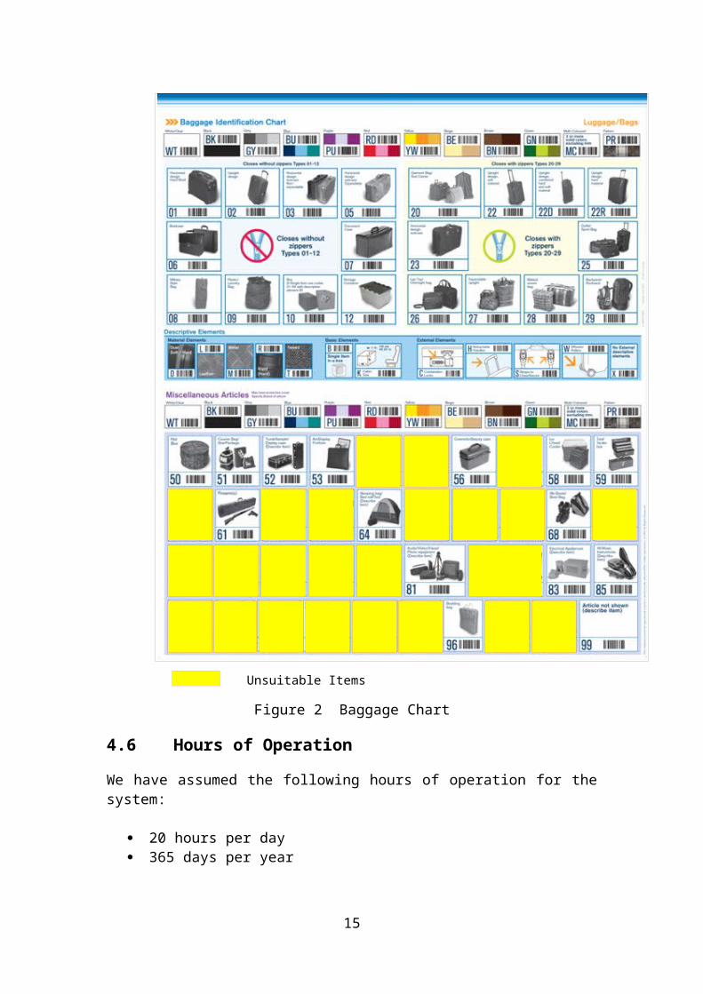
4.5.1. The system can transport all standard baggage defined in the baggage identification chart. Items unsuitable for loading by the BHS system are highlighted, and must not be loaded into the system.
4.5.2. Loose and trailing straps should be made secure before input to the system. Bags with unusual or unstable shapes should be placed in a suitable tote or tub, or handled by other methods.
4.5.3. Bags with wheels should be loaded ensuring the wheels are not in contact with the conveyor belts.
10

Unsuitable Items
Figure 2 Baggage Chart
4.6 Hours of Operation
We have assumed the following hours of operation for the system:
20 hours per day 365 days per year
11

4.7 Environmental Conditions
We have assumed the following: 5 to +40C Temperature range. 10 to 90% Relative Humidity. No other unusual conditions.
4.8 Compliance with the European Machinery Directive - 2006/42/EC
4.8.1. The conveyor system as a whole is considered to be a single machine under the scope of the European Machinery Directive and is CE marked as a system. Individual conveyors will not be CE marked, as the safety of individual conveyors and compliance with the safety directive is dependent on its installation in the overall system. If any conveyor is removed and re-used at a later date, then the system into which it is incorporated must be assessed in terms of machinery safety before it can be put into use.
4.8.2. In accordance with BS EN 121001-1 & -2, BS EN 349, BS EN 294, & PD5304-2000, fixed removable guarding is provided for all drives and moving parts where there is the risk of drawing in, trapping, or entanglement of personnel. Conveyor junctions are fitted with raised sidewalls as necessary. Where this is not possible, or where personnel or public access is required as part of the operational function of the system, appropriate safety devices will be provided to ensure that conveyors and machinery shut down to minimise the risk of injury.
4.9 Equipment Standards
4.9.1. Guarding of moving machinery must be in accordance with BS EN 121001-1 & -2, BS EN 349, BS EN 294, & PD5304-2000 as a minimum standard.
4.9.2. Electrical and controls design activities comply with 2006/42/EC and are in accordance with, BS EN 60204-1, BS EN 13849-1, BS EN 61439-1 & -2. Installation activities are controlled in accordance with BS 7671 - Requirement for Electrical Installations (IEE Wiring Regulations 17th Edition).
12

Conveyors L1-3 & L2-3
Conveyors L1-10 & L2-10
Level 3 Area
L3 MVT-HRX-ray
L3 MVT-HRX-ray
5. SYSTEM OVERVIEW
5.1. This section illustrates the mechanical and control system.
5.2. The existing system comprises of two lines, line 1 and line 2. Line 1 has 14 check-in desks, an X-ray and a HBS line feeding a carousel. This is controlled using one PLC panel and two remote I/O panels. Line 2 has 16 check-in desks, an X-ray and a HBS line feeding a carousel. This is controlled using one PLC panel and two remote I/O panels.
5.3. Line 1 is to be extended by 7 new check-in desks.
5.4. Two infeed conveyors (L1-3 & L1-4 and L2-3 & L2-4) prior to the X-ray on each line with one inclined conveyor (L1-3 and L2-3) Heimann X-rays with L3 MVT-HR machines and one declined transportation conveyor on each outfeed line (L1-10 and L2-10).
The control panels of each line with Siemens PLC platforms.
5.1 System Configuration
Figure 3 System Layout
The equipment consists of:
2 – Inclined queue conveyors.
13

2 – Transportation conveyors.2 – L3 MVT-HR X-ray Machines 1 – Line 1Check-in PLC System - Siemens S71 – Line 1Check-in Extension PLC System - Siemens S71 - HBS Line 1 PLC System - Siemens S72 – Check-in Line 2 PLC System - Siemens S71 – Line 2Check-in PLC System - Siemens S71 – Line 2Check-in Extension PLC System - Siemens S71 - HBS Line 2 PLC System - Siemens S7
5.1.1 HBS System (Line 1)
Figure 4 Hold Baggage Screening
The HBS system is composed of essentially two separate sub systems referred to as the ‘tracking’ and ‘transportation’ systems.
The tracking sub system is shown as shaded in the above diagram. The function of this sub system is to receive bags from the check-in line and convey them to the Level 3 decision conveyor. During this transportation of baggage they will pass through the X-ray machine, and a screening status will be received for each bag. The processes which will be performed during this phase is detailed in section 6.15.
Once the bag has been routed, dependent on its screening status, the bag will be transported to Level 3 X-ray or to the make-up carousel.
When the bag is transported to the make-up carousel, the bag will be injected into an available space.
14
5.1.2 Check-in and Check-in Extension
Figure 5 Check-in and Check-in ExtensionsThe system comprises of two lines, line 1 and line 2. Each line has a check-in panel and a check-in extension panel. Line 1 consists of desks 1 to 8 and 24 to 31. Line 2 consists of desk 8 to 23. Line 1 check-in panel consists of desk 1 to 7. Line 1 check-in extension consists of desks 24 to 31. Line 2 check-in panel consists of desks 8 to 16. Line 2 check-in extension panel consists of desks 17 to 23.
5.2 Control System Configuration Overview
5.2.1 PLC System Type
The PLC systems that provide the control of Line 1 and Line 2 are Siemens S7 Systems. All system control panels are configured from the same range of equipment.
5.2.1.1 HBS Line 1
Qty Part Number Description1 6ES7 318-3EL00-0AB0 CPU2 6ES7 340-1CH02-0AE0 CP340 Communication Processor RS4223 6ES7 321-1BL00-0AA0 32 Channel 24v DC Input Module3 6ES7 322-1BL00-0AA0 32 Channel 24v DC Output Module1 6ES7 972-0EM00-0XA0 TS Adapter inc Ethernet/Analogue Modem1 6AV6 647-0AA11-3AX0 3.8” Mono HMI Touch Buttom
5.2.1.2 HBS Line 2
Qty Part Number Description1 6ES7 318-3EL00-0AB0 CPU2 6ES7 340-1CH02-0AE0 CP340 Communication Processor RS4223 6ES7 321-1BL00-0AA0 32 Channel 24v DC Input Module3 6ES7 322-1BL00-0AA0 32 Channel 24v DC Output Module1 6AV6 647-0AA11-3AX0 3.8” Mono HMI Touch Buttom
A dial-in modem is included in the Line 1 panel to enable communication with the PLCs from a remote location.
15

5.2.1.3 Check-In Line 1
Qty Part Number Description1 6ES7 153-1AA03-0XB0 ET200 Interface Module2 6ES7 321-1BL00-0AA0 32 Channel 24v DC Input Module2 6ES7 322-1BL00-0AA0 32 Channel 24v DC Output Module
5.2.1.4 Check-In Line 2
Qty Part Number Description1 6ES7 153-1AA03-0XB0 ET200 Interface Module2 6ES7 321-1BL00-0AA0 32 Channel 24v DC Input Module2 6ES7 322-1BL00-0AA0 32 Channel 24v DC Output Module
5.2.1.5 Check-In Extension Line 1
Qty Part Number Description1 6ES7 153-1AA03-0XB0 ET200 Interface Module3 6ES7 321-1BL00-0AA0 32 Channel 24v DC Input Module2 6ES7 322-1BL00-0AA0 32 Channel 24v DC Output Module
5.2.1.6 Check-In Line Extension 2
Qty Part Number Description1 6ES7 153-1AA03-0XB0 ET200 Interface Module2 6ES7 321-1BL00-0AA0 32 Channel 24v DC Input Module2 6ES7 322-1BL00-0AA0 32 Channel 24v DC Output Module
5.2.2 Control Panels
Control panels are provided to house the PLC equipment, emergency stop zoning and terminations for local control enclosures for each control area.
5.2.2.1 New Panel Locations/Identifications
The six panel designations, sizes and locations are as follows:
Control Area Panel ID Panel Location Panel SizeL1 HBS CP1.1 Baggage Hall 1600mm wide x 2000mm high x 400mm deepL1 Check-In CP2.1 Baggage Hall 1200mm wide x 2000mm high x 400mm deepL1 Check-In Extension CP3.1 Behind desks
24 to 31 1000mm wide x 2000mm high x 400mm deep
L2 HBS CP1.2 Baggage Hall 1600mm wide x 2000mm high x 400mm deepL2 Check-In CP2.2 Baggage Hall 1200mm wide x 2000mm high x 400mm deepL2 Check-In Extension CP3.2 Baggage Hall 800mm wide x 2000mm high x 400mm deep
16

5.2.2.2 Existing Panel Locations/Identifications
The panel designations, sizes and locations are as follows:-Control Area Panel ID Panel Location Panel Size
L1 Bag Sep CP2 Adjacent to conveyor L1-3 500mm wide x 500mm high x 300mm deep
L1 Carousel CP3 Inside make-up carousel 500mm wide x 500mm high x 300mm deep
L2 Bag Sep CP5 Adjacent to conveyor L2-3 500mm wide x 500mm high x 300mm deep
L2 Carousel CP6 Inside make-up carousel 500mm wide x 500mm high x 300mm deep
5.2.2.3 Push Button Colours
Green StartRed StopRed mushroom head Emergency StopGeneral Black
5.2.2.4 Indicator Light Colours
White Power OnGreen System Running
Normal OperationRed E Stop OperatedAmber/Yellow Abnormal Condition / Fault
5.2.3 Field Mounted Devices and Controls
The following summarises the types of field device used.
Device Description Application Manufacturer Part NumberProximity Photocell
Bag Sep arrays / Carousel merge Erwin Sick WT27-2F410
Retro-reflective Photocell
General use on conveyors for baggage detection Allen Bradley 42GRU-9200-QD
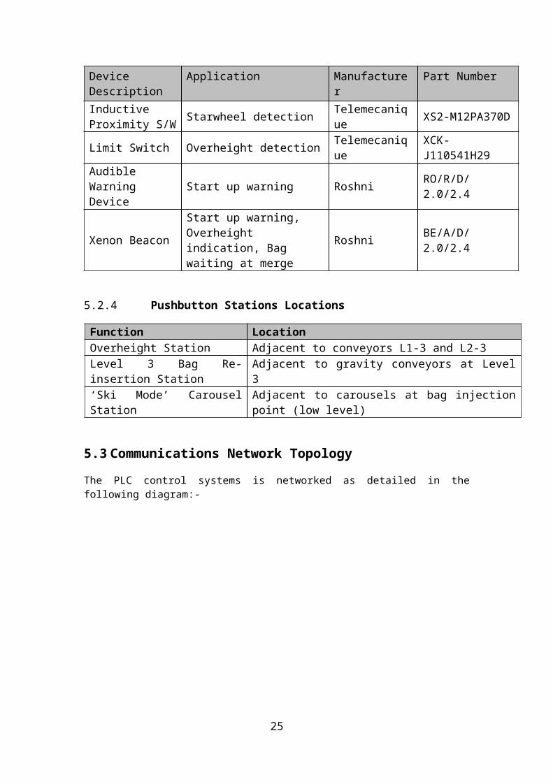
Inductive Proximity S/W Starwheel detection Telemecanique XS2-M12PA370D
Limit Switch Overheight detection Telemecanique XCK-J110541H29Audible Warning Device Start up warning Roshni RO/R/D/2.0/2.4
Xenon BeaconStart up warning, Overheight indication, Bag waiting at merge
Roshni BE/A/D/2.0/2.4
17

5.2.4 Pushbutton Stations Locations
Function LocationOverheight Station Adjacent to conveyors L1-3 and L2-3Level 3 Bag Re-insertion Station Adjacent to gravity conveyors at Level 3‘Ski Mode’ Carousel Station Adjacent to carousels at bag injection point (low level)
5.3 Communications Network Topology
The PLC control systems is networked as detailed in the following diagram:-
Figure 6 PLC Network Topology
The control network links all the PLC sub systems on Line 1 and Line 2 together. This is carried using Profibus.
Line 1 and Line 2 have their own independent Profibus networks.
Line 1 and Line 2 is communicating with each other using an Ethernet connection.
18

5.4 MVT-HR/BHS Interface
The following diagrams shows the X-ray/BHS interface.
5.4.1.1 VIS-HR Mainframe Control Interfaces Diagram
Figure 7 MVT-HR/BHS Interface
19

5.4.1.2 X-ray Interface Board & Connection Points
Figure 8 MVT-HR Interface Board Diagram
5.4.2 MVT-HR to BHS Serial Communications
The level 1/2 decisions and bag ID assignment uses the RS422 communications ports cabled using four twisted pair cabling.
20

5.4.3 Electrical Supply
Logan Teleflex (UK) Ltd control panels are designed to accommodate the European standard voltage for the U.K., which is 400 volts ac +10 % -6% (376 - 440 Volts). The supply is 3-phase, 50 Hz. +/- 2% with separate Neutral and Earth conductors.
5.4.4 Control circuit voltages
The control circuit is 24 VDC. The 0V line will not be grounded.
5.4.5 Local Lighting Supply
The internal panel lights operate from a 220 volt, single phase supply.
21

HMI DisplaySee Figure 22
6. SYSTEM OPERATION AND CONTROL STRATEGY
This section describes in detail the control devices, the system operation and the controls strategy utilised for system.
6.1 Modes of Operation
Operator pilot devices (Pushbuttons etc.) are located upon the Main Control Panel (MCP) for each control area. Operators can instigate start & stop functions from the MCPs.
The following figure shows the start/stop controls and pilot devices that are mounted on the Main Control Panel for lines 1 and 2:
Figure 9 Main Control Panels and Fascias
22

6.1.1 HBS Sub System
The two HBS sub systems are started independently thus it is possible to run only one of the systems if required. The make-up carousels at the end of the conveyor lines are also controlled from this location as part of the main conveyor lines and start and stop with the main conveyors.
6.2 Start Up
The Lines 1 and 2 are started from their associated Main Control Panel via push buttons.
For a system to be able to start, the following pre-requisites must be satisfied:
All relevant e/stop systems must be healthy & in the reset state. There are no relevant system faults
An audible and a visual warning is given for each sub-system; for a pre-set time prior to any conveyor module starting.
There are various start-up sequences for the different aspects of the system. Each individual component has been designed and integrated to provide the most flexible system possible, hence the start-up sequences have to take this into account.
In general the start-up cascade of drives occurs in reverse order, i.e. downstream to upstream.
The cascade starting is controlled by monitoring the conveyor speed sensing device, when the downstream conveyor is up to speed the next upstream conveyor is started. For conveyors without speed sensing devices fitted, the cascade start will be controlled by a 1 second timer.
6.3 Shut down
System shutdowns are initiated via “SYSTEM STOP” pushbuttons upon the Main Control Panels.
The following shutdown sequences are “controlled shutdowns” that attempt to clear the entire system of baggage. As baggage progressively clears from upstream to downstream, cleared conveyors are stopped.
In the shutdown sequence, all diebacks are accounted for, in so far as run-out timers are frozen whilst the relevant conveyor is stationary.
(The term clearance time = how long a conveyor will run prior to stopping - following shutdown of the upstream belt. The clearance time is reset if the header PEC detects baggage, in general clearance time is equal to 1/2 a complete revolution of the belt).
23

When the operator activates the conveyor “stop” command, the check-in desk controls shall be inhibited and the controlled shutdown activated by the control system.
This “controlled shutdown” is the preferred method of stopping the system under normal conditions. Emergency Stop activation’s kill the system immediately and therefore no baggage clearance takes place.
6.4 Emergency Stop/Safety Systems
The system is fitted with devices for stopping the conveyors in an emergency or safely during normal operating procedure. These devices are of the following type:
Telemecanique E-Stop Mushroom headed push buttons: ZB4-BS844.
6.4.1 Emergency Stop Philosophy
All devices are hardwired to the associated panel (MCP) where emergency stop relays detect device operation. Upon tripping, a hardwired positively guided normally closed contact of the emergency stop relay removes the “common” 24vdc supply to the associated feed contactor within the start panels. This ensures that each conveyor is stopped in the quickest possible time.
Also, for inverter controlled drives, upon tripping, these units shall instantaneously remove the “common” 24vdc supply used to feed the associated inverter ‘run’ signals. A hardwired ‘delay to open’ contact of the emergency stop relay shall remove the “common” 24vdc supply to the associated feed contactor within the start panels. This ensures that each conveyor is stopped in the quickest possible time.
No local indication shall be given but there will be indication on the MCP fault displays. Panel fascias shall provide indication as to which ‘zone’ has been activated.
Activation of an emergency stop device shall not corrupt any controls operations. However, the system’s ability to recover/auto flush critical conveyor lines following an e/stop is clearly dependent upon the reason for the activation.
6.4.2 Stopping the System in an Emergency
To stop the system in an emergency an operator must simply strike the nearest e/stop push-button. Emergency stop buttons will latch in upon activation. Even if the device is accidentally reset, the associated e/stop unit will have “dropped out” and the system shall therefore remain in the safe state.
Field e/stop devices only stop the conveyors within their associated zone including the defined zone overlap conveyors.
An emergency stop push-button is fitted to the front of the Main Control Panel. Activation of this push-button de-activates (or KILLS) the entire system.
24
Line 2 Zone 1
Line 2 Zone 2
Line 2 Zone 3
Line 1 Zone 1
Line 1 Zone 2
Line 1 Zone 3
6.4.3 Re-start Procedure
After activation of any emergency stop device, the following standard operating procedure must be implemented:
1. The ‘EMERGENCY STOP OPERATED’ lamp illuminates on the systems associated MCP, indicating that an emergency stop device has been operated.
2. Investigate the nature of the stoppage to check safety of all personnel/others.3. Once it is established that it is safe to re-start, reset the operated device(s) locally.4. Reset the system using the ‘EMERGENCY STOP RESET’ keyswitch on the MCP.5. Then following the ‘normal starting procedure’, restart the system.
ALWAYS ENSURE THAT ALL PERSONNEL ARE ACCOUNTED FOR BEFORE RESETTING ANY EMERGENCY STOP SITUATION.
NEVER USE THE EMERGENCY STOP SYSTEM AS MERELY A MEANS OF SHUTTING THE CONVEYORS DOWN - THIS LEADS TO COMPLACENCY WITH REGARDS TO THE SUBSEQUENT RE-START PROCEDURE.
6.4.4 Emergency Stop Zoning
The two departure lines are each split into 3 emergency stop zones.
Figure 10 Emergency Stop Zoning
25

Operation of ANY e/stop device within a zone immediately stops ALL conveyors within that zone. Where one zone is adjacent to another zone with a conveyor line which runs between both zones, a conveyor is designated as a zone overlap conveyor, meaning that it will stop upon activation of either zone’s e/stop activation.
The emergency stop zones for the two lines work independently from one another.
The following details the E-stop Zones. This applies to both Line 1 and Line 2.
6.4.4.1 Zone 3 – Check-In
All conveyors which are located within the check-in area up to and including either L1-02 or L2-02 are controlled by this zone.
The reset point for this zone is the MCP in the baggage hall or the screening room operator station using the zone 1 reset keyswitch.
If zone 3 emergency stop circuit is tripped the zone 1 emergency stop light flashes on the MCP and screening room operator station and the zone 3 tripped alarm displayed on the HMI.
6.4.4.2 Zone 1 – HBS
The conveyors in the screening room from L1-03 or L2-03 to L1-14 or L2-14 are controlled within this zone.
The emergency stop zones for the two HBS lines work independently from the other. If an emergency stop is operated on Zone 1 of Line 1, this will not stop the conveyors on Line 2.
The reset point for this zone is the MCP in the baggage hall or the screening room operator station using the zone 1 reset keyswitch.
If zone 1 emergency stop circuit is tripped the zone 1 emergency stop light will illuminate steady on the MCP and screening room operator station and the zone 1 tripped alarm displayed on the HMI.
6.4.4.3 Zone 2 – Carousel and Transportation from HBS Conveyors
All conveyors on the lower floor level and the departure carousel are controlled within this zone, from L1-15 or L2-15 to L1-19 or L2-19.
The emergency stop zones for the two HBS lines will work independently from the other. If an emergency stop is operated on Zone 1 of Line 1, this will not stop the conveyors on Line 2.
The reset point for this zone is the MCP in the baggage hall or the screening room operator station using the zone 2 reset keyswitch.
26

If zone 2 emergency stop circuit is tripped the zone 2 emergency stop light illuminates steady on the MCP and screening room operator station and the zone 2 tripped alarm displayed on the HMI.
6.5 HBS system incorporating screening, routing and carousels
6.5.1 Line 1 Operation
Figure 11 Line 1 Operation
Baggage to be security screened by the HBS system is presented via the existing check-in lines. If baggage is loaded via the ‘oversize’ check-in desk then the collector conveyor is stopped to allow the passage of baggage.
An overheight check is to be performed prior to the X-ray entrance. The conveyor section as indicated on the above diagram (in orange). Bags that fail these checks are stopped on the highlighted conveyors awaiting removal/re-orientation.
It is the operator’s responsibility to determine whether a bag is overweight and not load it to this system if it is.
The default route for miss-tracks is the Level 3 area.
All conveyors operate with dieback control and provide jam detection.
Line 2 operates in the same way as described above.
27

“Window”Despatch
Weigh/Label
Collector Conveyor
6.6 Check-In Procedure – 2 stage
This section describes the procedure for positioning and despatching check-in baggage. Each Check-In desk is fitted with a remote pushbutton console.
Figure 12 Two Stage Check-in Desk
6.6.1 Check-In Desk Console Operation
The “START” pushbutton allows the operator to “inch” the weigh/label conveyor so that baggage can be positioned to assist in label placement.
The “TRANSFER” pushbutton causes the bag upon the weigh/label conveyor be transferred to the despatch conveyor. Once the bag has stopped on the despatch conveyor, utilising a virtual PEC, it will request a “window” upon the collector conveyor. When the assigned “window” reaches the check-in desk position, the bag is automatically driven from the despatch conveyor onto the collector take-away line.
6.6.2 Check-In Desk Summarised Procedure
After the desk has been enabled the check-in procedure is therefore as follows:
Both weigh_conv & despatch_conv are empty.
Passenger places bag_one onto weigh_conv. Operator checks weight and advances bag_one forward using the “START”
button. bag_one stops when the operator releases the “START” button. To despatch a bag, the operator depresses the “TRANSFER” button. The bag
is transferred onto the despatch_conv. At this point, the control system “calls” for a next available collector_conv “window”.
When bag_one is on the despatch conveyor the operator can now place bag_two onto the weigh_conv.
As the “window” passes despatch_conv, bag_one is injected onto collector_conv.
28

despatch_conv is now available for bag_two, this is actioned by again depressing the “START” button and following the same procedure for bag_one above. Note that only one bag must be placed on the despatch conveyor at one time.
6.7 Energy Saving Operation
All of the conveyors have an automatically selected energy save mode.
The photocell on each conveyor is used to determine when baggage is passing through the conveyor. If the photocell remains clear for longer than 5 minutes on a conveyor it is put into the energy saving mode. This causes the conveyor to stop but remain ready for service. In this way energy saving mode tends to cascade through the system some 5 minutes after the last bag went through a particular route.
Recovery from energy saving mode is achieved by the photocell being covered on the preceding conveyor or in the case of a merge junction, one of the preceding conveyors. This causes the conveyor in question to restart immediately.
Thus, when the system is in energy saving mode, loading a bag onto one of the loading points causes the route that that bag follows to cascade start as the bag passes through the system.
In this case, an audible warning does not precede re-starts.
6.8 Point of Control
The term “Point of Control” describes the system element from where overall operational commands are initiated. In this project there is a primary ‘point of control’, manually operated pushbuttons upon the front fascia plate of the MCP.
The emergency stop safety trips can only be reset from one point of control situated on the MCP fascia.
6.9 100% HBS Procedure
Figure 13 HBS Tracking Area
29

The area of the system with the HBS tracking is illustrated in Figure 13 HBSTracking Area.
The HBS functionality of the system is comprised of an automatic Level 1/2 X-ray screening machine (L3 Communications MVT-HR), and the level 2 screening operators who apply level 2 decision’s to bags rejected at level 1 by the machine. In addition there is a Level 3 machine (L3 PX-213) and a level 3 operator.
The Level 1 machine will be networked to Level 2 workstations which allow security screening operators to view automatically failed level 1 bag images and make level 2 clear or reject decisions.
The Baggage Handling System (BHS) communicates with the X-ray machines and tracks the Security screening decisions with the bag as it exits the machine. The BHS automatically assigns each item of baggage an identifying number known as the ‘BAG ID’. This reference is then used by BHS and the X-ray machine to reconcile Security decision data with the bags in transit.
6.9.1 Automatic Security Level 1 Screening
As baggage passes through the MVT-HR X-ray machine an automatic Level 1 clear or reject security decision upon the bag is made.
6.9.2 Security Level 2 Screening
If a bag fails the Level 1 automatic check its image issent to a Level 2 operator workstation.
As the baggage is tracked along the series of conveyors towards the level 2 decision point the level 2 operators examine the failed Level 1 bag images and manually make a Level 2 clear or reject decision.
The control system tracks the bags to the Level 2 decision point and routes the bags accordingly depending upon the Level 1/2 clear/reject decision status. This is done by a divert conveyor downstream of the X-ray. If a bag has a clear Level 1 or 2 decision status then it is routed to the make-up carousel. If however a bag has a reject status then it is routed to the level 3 X-ray for further screening.
Final baggage routing is checked within the software control to determine correct sequence completion.
6.9.2.1 Automatically Rejected Level 2 Baggage
If a level 1 reject bag arrives at the Level 2 decision point, and has not received an operator level 2 workstation decision; it will then be automatically given a level 2 reject status by the control system and sent to the level 3 X-ray. A warning indicator located in the Screening room will flash to alert operators that baggage is being automatically rejected.
This warning indicates that an additional Level 2 Workstation should be manned in-order to share the task of processing images sent from the MVT-HR machine.
30

Figure 14 Screening Room Beacon
6.9.3 MVT-HR Machine - Show All Bag Images Mode
It is possible to set the MVT-HR machine to “Show All Bag Images” mode. This mode is selected manually via a two position key switch device linked to the BHS.
In “Show All Bag images” mode the Level 2 operator receives an image of every bag and can then make a manual clear or reject Level 2 decision. The bag is then routed accordingly as described in section 6.9.2 In this mode of operation the MVT-HR machine doesn’t make automatic Level 1 decisions. All screening decisions are made by the operator.
The key-switch can toggle between “Normal” automatic mode (As described in 6.9.1), or “Show All Bag images” mode.
If the “Show All Bag images” mode is selected then a lower system throughput should be expected. This is because the operator has to check all bag images as opposed to only the Level 1 automatically rejected images, when operating in “Normal” mode.
Figure 15 Show All Bags - Mode Switch
31

RESTART NEW BAG
6.10 Level 3 Baggage
This section describes the semi-automatic procedure governing the accumulation of baggage at the Level 3 area.
It is the responsibility of Riga Airport to ensure that ALL standard operating procedures are adhered to.
A locally mounted operator Remote Pushbutton Station is used to initiate the procedure and has the following control devices:
Figure 16 Level 3 Baggage Remote Pushbutton Station
The procedure is as follows:
1. Once a bag has reached the photocell on the conveyor preceding the divert (L1-12, L2-12), then the status of the bag will be checked. If the status is CLEAR then the conveyor will run in its normal mode of operation and the bag will be transported to the make-up carousel.
2. If the bag in question has a REJECT status and the divert conveyor is clear, then the bag will be routed to the Level 3 gravity. If the gravity is blocked then the divert conveyor will be placed in dieback. A label is no longer printed when the bag reaches the gravity conveyor as this functionality has been removed.
3. Once the bag has been further screened, and has been accepted as clear, the bag can be re-introduced into the system. The bag will be placed on the gravity conveyor and the ‘new bag’ pushbutton depressed. The pushbutton will then flash to indicate the request has been accepted. Once the system is able to accept the bag the conveyor preceding the divert conveyor will be placed in dieback, the divert conveyor will run in normal mode and the lamp will be steady. If no bag is detected at the photocell before a pre-set time, then the system will revert to normal operation and the pushbutton will have to be operated again.
Pre-start warnings are not given during any part of this procedure.
6.11 Level 3 Screening Areas
6.11.1 Departure Level 3 Screening Area Introduction
Level 2 Reject bags and miss-tracks are transferred from the sub-systems on to the Level 3 area for further screening. Once the bags have been re-screened, if they are deemed to be clear then they are re-introduced on to the transportation sub-system.
32

There is no requirement to communicate baggage details to the MVT-HR machine for level 3 screening use.
6.11.2 Departure Level 3 Screening Area Operator Procedure
The following describes the procedure for receiving and sending Level 3 baggage from and to the sub-systems.
1. Baggage will be conveyed from the X-ray machine through the system to the Level 2 decision point. This point is the photocell on the conveyor preceding the divert conveyor (L1-11, L2-11).
2. With the downstream conveyor clear, the status of the bag determines which way the divert conveyor runs. If the status is CLEAR the conveyor runs in its normal direction and transports the bag to the make-up carousel. If the status is REJECT then the conveyor direction is reversed so that the bag is transported to the Level 3 area.
3. Once the bag has been processed by the Level 3 X-ray machine and has been cleared, it is now to be re-inserted to the system. The bag is placed onto the gravity and the ‘new bag’ pushbutton operated.
4. The pushbutton lamp flashes to indicate that the request to re-insert a bag has been received. Once the system is ready to accept this bag the pushbutton lamp is illuminated continuously. The operator then pushes the bag onto the conveyor. If the system does not detect the bag within a pre-set time, the divert conveyor will be reversed and the bag is transported back to the gravity conveyor. After this, the system is restarted and the re-insertion process has to be repeated.
6.11.3 Re-Scanning Baggage
Re-scanning baggage allows operators to re-check bags manually if they have any doubts or require more time to make a decision on an item of baggage.
If a bag is to be re-scanned, it is the responsibility of the Level 3 operator to keep re-scanning the bag until a final Level 3 decision has been made.
6.11.4 Control Responsibility
This area is totally under the control of the Level 3 operator, he/she is responsible for the flow of baggage through the X-ray machine. Only one bag should ever be dealt with at one time.
6.12 Over Height Checks
The maximum height of standard baggage expected upon the system at the Over-Height checkpoint is 630mm.
The mechanism for detection is a hinged steel frame that hangs vertically above the conveyor. The frame’s lower edge is adjustable in the range 630mm to 650mm from
33

the conveying surface. As baggage deflects the frame, a striker upon the plate is drawn away from a fixed position, limit switch roller arm. A slight deflection (e.g. caused by bag labels) will not cause the limit switch to switchover, however items approaching the set striker plate level will cause a trip.
Upon an overheight bag being detected the conveyor upon which the detection is performed will stop. A visual warning will alert operators that an overheight bag has been detected. To re-start the conveyors following rectification / removal of the bag the operator depresses a button upon a locally mounted push-button station.
6.13 Baggage Separation and Pitching
6.13.1 Bag Separation
The baggage separation unit on both Lines 1 and 2 prior to the X-ray will be removed. One long conveyor is to be installed as part of these works (L1-3 and L2-3) in place of the separation conveyors (L1-3/L1-4 and L2-3/L2-4). The new MVT installation only allows one queue conveyor prior to the X-ray due to its larger size and therefore the separation unit functionality (as it requires three queue conveyors) will be removed. The new motors (L1-3 and L2-3) are wired back to the separation unit and are used only as single speed motors and not for separation.
6.13.2 The Pitching Philosophy
Bag pitching functionality will be utilized prior to the X-ray entrance and prior to the level 3 divert to ensure bags are correctly spaced. Ultimately the pitch and gap will be regulated to ensure correct separation and flow with regards to the thru-put capabilities of the X-ray machine and the entire system.
34

PEC-A1 PEC-B1 PEC-C1
A B CFlow
6.14 Software Control Techniques
6.14.1 Dieback Control
Dieback control is a general control technique applied to transportation conveyors to manage bag flow ensuring conveyors cannot discharge a bag into an unavailable or stationary downstream position.
Figure 17 Dieback control
Under normal conditions, bags travel along the conveyors crossing A and B and C sequentially. If conveyor C stops moving, conveyors B and A will continue to run until a bag obscures PEC-B1, conveyor B will then stop. Whilst B is stopped conveyor A will continue to run until a bag obscures PEC-A1, then conveyor A will also stop.
When the downstream stoppage is removed and conveyor C runs, conveyors B and A will re-start delay, after a short.
Die-back control is not applied during emergency stop conditions.
6.14.2 Special Dieback Cases
6.14.2.1 X-ray machines
A special case for dieback is at the screening machines where bags must not be stopped through dieback in the X-ray machine. In these cases, when dieback reaches the conveyor which is two conveyors downstream of the X-ray conveyor the conveyor before the X-ray conveyor is stopped when the next bag arrives. This allows any bag in the X-ray machine to discharge from the machine to the conveyor downstream of the X-ray where it is stopped.
6.14.3 Carousel Merge Control
The following describes the ‘space available’ merge control technique used for the carousel conveyor merges. See Figure 18 Carousel Merge below.
When a bag is detected at PEC-A1, conveyor A is stopped until sufficient space on conveyor C exists, into which the bag can be injected. Photocell PEC-C1 is positioned upstream of the merge point to detect space in the baggage stream on conveyor C.
35

PEC-C1
Flow
PEC-A1A
C
Flow
Figure 18 Carousel Merge
6.15 Hold Baggage Screening
6.15.1 Strategy Overview
The purpose of the ‘HBS’ Hold Baggage Screening’ software solution is to accurately reconcile X-ray screening decisions made by the interfaced X-ray systems to the real baggage travelling along the conveyors.
The solution provides fail-safe software algorithms for the tracking of baggage, reconciling of decisions and routing of passenger luggage. The system is as far as reasonably practicable tolerant of unpredictable characteristics inherent in any system when conveying baggage of varying types.
The nature of the HBS systems suggests a high accuracy for tracking of the bags is of paramount concern. However, although a control system solution may offer very high resolution tracking (where the accuracy is +/- one scan of the software, typically 40ms) in reality baggage cannot be conveyed with such precision due to inherent slippage of baggage as it travels from conveyor to conveyor.
Larger tracking error tolerances can be applied to the checking algorithms within the software so that the system is very tolerant of conveying inaccuracies. However this reduces the systems effectiveness when identifying tampering with or exchanges of baggage scenarios.
Thus, the situation exists where the smaller the tolerances are, to satisfy ‘security’ requirements the greater will be the occurrence of bags rejected as ‘miss-tracks’. Conversely, increasing the tolerances will reduce reject rates but will also reduce the level of ‘security’ offered.
LTUK have commission the HBS system with standard tracking tolerances. These values are tried and tested defaults for HBS tolerances. These offer ‘miss-track’ rates in the order of 1%. Fine tuning of the system parameters maybe required once the system has gone into service. Should adjustments be necessary after the system has gone ‘live’ i.e. into beneficial use by the client, it must be understood that this is the normal course of events for an HBS system and does not in any way indicate a failure of the control system.
36
PEC
Flow
STAR WHEEL
50mm BELT SECTION := 1 MEMORY WORD
6.15.2 “HBS_TRACK”
“HBS_TRACK” is LTUK’s ‘Hold Baggage Screening’ tracking and interface control package.
Tracking, checking and routing are controlled by software resident within the baggage handling system PLC.
6.15.3 PLC Software
With respect to HBS functions, the PLC software is responsible for:
Controlling communication with the X-ray Maintaining the TRACKING_TABLES for each HBS conveyor Maintaining the BAG_STATUS_TABLE Reconciling inbound decisions to the relevant tables Controlling the Routing of the system components
6.15.3.1 TRACKING_TABLES
Each conveyor between and including the Level 1 X-ray machines and the level 2 decision point, is assigned an area of contiguous memory that make up a TRACKING_TABLE.
The conveyors are modeled within the PLC memory as a series of 16 bit words. Each word represents a 50mm slice of the conveying surface, therefore a typical HBS queuing conveyor measuring 1200mm has 24 words assigned to it.
Figure 19 Tracking Model
The Bag Tag is written to these words. As ‘star wheel’ pulses are received the PLC moves the data along the words. Each word holding a Bag-Tag represents 50mm of bag length; i.e. a bag with the Bag Tag 23 and measuring 400mm in length would be represented within the PLC memory as a series of 8 contiguous words each containing the value 23.
It can be seen therefore, that the memory model is a series of ‘live’ tables containing Bag Tags, with the additional feature of also being representative of bag length. By
37

indicating bag length within the tables, it is possible to identify when a ‘real’ bag should or should not be passing a photocell upon the conveyor. This feature allows the model to be checked and if necessary updated as the ‘real’ bag passes each photocell.
Slippage or other movement of the ‘real’ bag in relation to the one held within the model can be measured. If the movement is found to be within an acceptable tolerance (adjustable), then this small error is corrected by ‘moving’ the model within the table. This is done at each photocell upon the system, thus eliminating accumulative errors. If the slippage or other movement is found to be outside of the acceptable tolerance, then the decision data for that bag (held within the BAG_STATUS_TABLE) is forced to the ‘reject’ state and the ‘real’ bag is subsequently rejected.
The flow of data from one TRACKING_TABLE to the next is set up during commissioning so as to ‘tune’ the overall conveyor line.
6.15.3.2 BAG_STATUS_TABLE
This table is a series of 999 words. Each word holds a status bit pattern for a particular bag. The Bag Tag is in fact a pointer to the position within this table.
As a bag enters the X-ray beam, the X-ray mainframe requests a BAG_ID to be issued by the PLC. The PLC assigns the next rolling number to the bag (000 to 800) and instructs the PLC serial communications card to forward this information to the X-ray mainframe. As the PLC assigns the next rolling number, it also writes a default bit pattern into the words represented by the BAG_ID (Bag Tag). This bit pattern gives the bag a default ‘reject’ status.
If and when Level 1-2/3 decisions are received by the PLC, the PLC updates the status bit pattern associated with the BAG_ID. If no such decision is received, the bag retains its default ‘reject’ status.
The bit pattern indicates not only the basic ‘clear’ / ‘reject’ status of a bag but also gives information as to the nature of the ‘reject’ decision (e.g. screening equipment decision, time-out etc.)
6.15.4 Bag Slippage/Tampering
As each bag is introduced onto the HBS tracking conveyor, immediately after the X-ray, its position will be recorded. As each bag is transferred from one tracking conveyor to another, a check is made to ensure that the bags arrive at the next downstream photocell when the tracking software expects them to. Failure to arrive on time or arriving too early could indicate that the bag has slipped or been tampered with. In such an instance, the control system shall automatically over-write the bag’s decision with a “reject” code.
In practice it is not possible to convey items such as random baggage without suffering some slippage or item displacement, thus the tolerance detailed in section 4.4 is applied to the checks. The level of ‘miss-tracks’ is directly proportional to the tolerance applied.
38

12
A B
6.15.4.1 Bag Movements
Figure 20 Wheeled Bags
In Figure 20 Wheeled Bags Bag 1 has its wheels on the conveyor and is likely to skate along the conveyor when it is running, this has the effect of changing the bags position with respect to the belt, creating a tracking position error.
Bag 2 illustrates the possibility of position errors occurring if a protrusion such as a wheel or loose strap catches in the joint between two conveyors, as with bag 2 this would create a tracking position error.
6.15.4.2 Unexpected / Extra Bag
Figure 21 Bag Straps Moved
In Figure 21 the bag moves from position A to position B and in doing so the bag strap changes position. Dependent upon the strap type, the control system may interpret this condition as an unexpected or extra bag if the gap between the bag and its strap is sufficiently large.
If a bag is randomly inserted onto a tracking conveyor then it will also be deemed an unexpected or extra bag.
6.15.4.3 Summary
The examples given indicate various ways in which the baggage can produce tracking errors.
New bag inserted into stream (Extra bag) Bag Strap moves whilst bag is travelling (Extra Bag) Bag slippage whilst bag is travelling
39

It is not possible to accurately quantify the frequency of occurrence of the illustrated problem types. However based on numerous previous Hold Baggage Screening projects which it is assumed would contain the same quantity of baggage likely to introduce tracking errors, we have achieved tracking error rates of 1% or better with the tolerances set as detailed in section 4.4.
*Note. Some X-ray machines have lead curtains that due to their weight may drag a light (less than 5kg) bag back on the X-ray conveyor. If this happens there is a chance that the bag may move further than the system tolerance setup for bag movement and the bag would be classed as a miss-track and sent to level 3. Any bags that are miss-tracked here would be in addition to the 1% of tracking error rates mentioned above.
6.16 HMI Display & Control
The main control panel is provided with an HMI display (KTP400) for the display of system status messages and alarms.
Figure 22 Alarm Display – 6AV6 647-0AA11-3AX0
6.16.1 Messages and Faults
The control system is configured to detect a range of standard faults;
Conveyor PEC Blockage, Motor Overload Tripped, Security Door Fault, Carousel Inverter Fault, E/Stop Zone Tripped.
On fault detection a message will be displayed on the HMI device describing the fault. If several faults exist simultaneously, they will be listed on an alarms page, and continue to be displayed until the fault has been rectified.
6.16.2 Fault Reset Procedure
40

On activation of a fault the amber fault light on the control panel will be illuminated, and an error message will be displayed on the HMI device.
The fault message display should be interrogated to establish what fault is active
The fault should be investigated, and the cause of the fault removed or corrected
When the cause of the fault has been rectified the fault reset button can be pressed. An audible warning will sound for 10 seconds before a reset command is issued. Care should be taken as conveyors will start automatically on fault resetting.
6.17 System faults
6.17.1 Bag Jam
Each transport conveyor is fitted with a photocell at its discharge end. If this photocell is obscured for longer than a pre-set time period (typically 4 seconds) a blockage will be deemed to have occurred. On this event the conveyor section affected will be stopped and an alarm generated at the control panel
The blockage must be removed manually and the fault reset function on the control panel operated before the conveyor/s affected by the blockage will restart.
Conveyors upstream of the fault will stop in dieback while the fault exists.
6.17.2 Rotation Failure
Some conveyors are fitted with a star-wheel device to generate pulses for baggage tracking and motion detection. If a conveyor is running, and the impulse train received by the control system does not comply with pre-defined limits, a rotation failure alarm in generated. On this event the conveyor section affected will be stopped and an alarm generated at the control panel.
The failure must be investigated and corrected and the fault reset function on the control panel operated before the conveyor/s affected by the fault will restart.
Conveyors upstream of the fault will stop in dieback while the fault exists.
6.17.3 System power failure
On power loss all conveyor functions will stop.
On restoration of system power after a failure, the system will be in the stopped state.
To restart the system refer to the procedure in section 6.2.
There is no technical reason to remove baggage from the system during a power outage, however for operational reasons or if it is deemed necessary by the security personnel, bags can be removed manually with no detrimental effect on the restart actions given above.
41

7. OPERATIONAL ISSUES
During normal operation, Departures HBS Lines 1 and 2 are started and stopped via their associated Main Control Panels.
7.1 Fault Finding
Line faults that occur on the HBS lines are indicated by the yellow ‘SYSTEM FAULT’ lamp illuminating on the relevant MCP control interface and an error message being displayed on the MCP HMI display.
HBS line emergency stop zone device activation is indicated by the relevant MCP Zone ‘1 or 2’ ‘ESR OPERATED’ lamp illuminating and an error message being displayed on the MCP HMI display.
NOTE: If Zone 1 emergency stop circuit is tripped the zone 1 emergency stop light
illuminates steady on the MCP and screening room operator station and the zone 1 tripped alarm displayed on the HMI.
If Zone 2 emergency stop circuit is tripped the zone 2 emergency stop light illuminates steady on the MCP and screening room operator station and the zone 2 tripped alarm displayed on the HMI.
If Zone 3 emergency stop circuit is tripped the zone 1 emergency stop light flashes on the MCP and screening room operator station and the zone 3 tripped alarm displayed on the HMI.
7.1.1 Resetting a System Fault or an Emergency Stop
After investigating the nature of a fault and rectifying it as described in the procedures below; return to the relevant control panel and press the ‘FAULT RESET’ pushbutton. An audible warning will sound for 10 seconds before a reset command is issued. Care should be taken as conveyors will start automatically on fault resetting.
Following an Emergency Stop condition reset the tripped e/stop pushbutton locally, in the relevant zone, and then reset the ‘EMERGENCY STOP RESET’ key switch on the relevant MCP.
After all emergency stops, the system is re-started using the ‘Normal System Starting Procedure’.
7.1.2 X-ray Machine Faults
X-ray machine status and faults are not indicated. Fault rectification information is provided in the manufacturer’s manual. If the X-ray machine fails to initialise after several reboots, contact the Technical Operators.
7.1.3 How to Rectify Faults Indicated on the Control Panels
42

Faults indicated on the MCP are listed below:
E/Stop Zone Tripped Conveyor PEC Blockage Motor Overload Tripped Carousel Inverter Fault Security Door Fault
The following procedures give step-by-step instructions for rectifying faults on the system.
7.1.3.1 Emergency Stop Activated
IDENTIFICATION
The HMI on the MCP indicates which device has been operated Relevant MCP ‘EMERGENCY STOP OPERATED’ lamp illuminates
NOTE:
If Zone 1 emergency stop circuit is tripped the zone 1 emergency stop light illuminates steady on the MCP and screening room operator station and the zone 1 tripped alarm displayed on the HMI.
If Zone 2 emergency stop circuit is tripped the zone 2 emergency stop light illuminates steady on the MCP and screening room operator station and the zone 2 tripped alarm displayed on the HMI.
If Zone 3 emergency stop circuit is tripped the zone 1 emergency stop light flashes on the MCP and screening room operator station and the zone 3 tripped alarm displayed on the HMI.
FAULT RESOLUTION
Reset the relevant E/stop pushbutton locally. Reset the relevant ‘EMERGENCY STOP RESET’ key-switch on the control
panel. Observe the related ‘EMERGENCY STOP OPERATED’ lamp going out. If the
lamp does not extinguish then check the ‘FAULT’ lamp to see if any other problem is indicated or if another E/stop is not activated.
When clear press the ‘SYSTEM START’ pushbutton on the relevant control panel.
If the Emergency Stop circuit is healthy, the system will start automatically.
43

7.1.3.2 PEC Blocked
IDENTIFICATION
Relevant MCP ‘SYSTEM FAULT’ lamp illuminates. An error message is displayed on the relevant lines MCP HMI display
FAULT RESOLUTION
Check to see if a bag is in front of PEC. If PEC is obstructed, isolate the conveyor and then clear the obstruction. If no lights are present on PEC, check the power supply within the MCP. If only the red light is lit on PEC, check alignment, clean reflector and PEC and
adjust as necessary. If the PEC cannot be re-aligned then it may be faulty, therefore, replace the PEC. Activate the ‘FAULT RESET’ pushbutton on the MCP. An audible warning will sound for 10 seconds before a reset command is issued.
Care should be taken as conveyors will start automatically on fault resetting.
7.1.3.3 Motor Overload Tripped
IDENTIFICATION
Relevant MCP ‘SYSTEM FAULT’ lamp illuminates. An error message is displayed on the relevant lines MCP HMI display
FAULT RESOLUTION
WARNING 400V WITHIN PANEL
Isolate the conveyor that has tripped via the local motor isolator. Is there an obvious reason why the Overload has tripped (e.g. too many bags)? If
so, then clear the problem. Turn the isolator back on. Reset the overload at the MCP. An audible warning will sound for 10 seconds before a reset command is issued.
Care should be taken as conveyors will start automatically on fault resetting. If the conveyor does not start and the overload trips again, check motor, check
overload settings, check wiring and/ or replace overload unit.
7.1.3.4 Inverter Fault
IDENTIFICATION
Relevant MCP ‘SYSTEM FAULT’ lamp illuminates. An error message is displayed on the relevant lines MCP HMI screen
FAULT RESOLUTION
44

! WARNING 400V WITHIN PANEL.
Isolate the carousel via the isolator on the MCP. Check for bag jams or other possible causes of overloading and remove. Re-instate the isolator. This has the effect of power cycling the inverter. The
General Fault light on the MCP should go out. Wait 10 seconds to allow the inverter to power up.
Activate either the ‘SYSTEM FAULT RESET’ pushbutton on the relevant MCP the relevant MCP and an audible warning will sound for 10 seconds before a reset command is issued. Care should be taken as conveyors will start automatically on fault resetting.
If the Inverter trips again then open the VSD and observe the fault code on the Inverter Display and investigate the nature of the fault. Rectify the problem.
7.1.3.5 Security Door Fault
IDENTIFICATION
An error message is displayed on the system relevant lines MCP HMI screen
FAULT RESOLUTION
Isolate the conveyor and the security door via the local motor isolators. Is there an obvious fault (e.g. too many bags)? If so, then clear the problem. If there are no obvious faults (loss of 3 phase or limit switch faulty) then fault find
to identify the problem. Once the problem is clear turn the isolators back on. Reset the fault at the MCP. Restart the system, using the normal procedure.
45

8. MAINTENANCE REQUIREMENTS
8.1. All maintenance actions should be carried out with reference to this document and to BS 6423 maintenance recommendations for electrical equipment up to and including 1000v. Maintenance is done by RIX.
Time Period Maintenance Actions
1 Week Clean and check alignment of PEC’s.
Check correct operation of proximity switches.
Perform lamp test and replace faulty devices as required. 1 Month All of the above.
Visually inspect exterior panels for dirt and damage, clean and repair as necessary. Test emergency stop devices for correct operation. Check correct operation of the security doors; adjust limits as necessary.
3 Months All of the above.
Inspect panel interiors for dirt and debris, clean interior if necessary.
12 Months All of the above.
Isolate panels and inspect motor control equipment for correct setting of overload devices. Electrically test drive motors and cables for insulation level and continuity values, record the results.
8.2. The Contractor should present complete set of maintenance documentation include list of all required maintenance procedures and all equipment and tools required to carry out those maintenances.8.3. The Contractor should propose a program and detailed instructions for preventive maintenance. Maintenance program should include all necessary actions and resources to be needed to carry out the proposed preventive maintenance.8.4. Design considerations should include at least, but not be limited to:
8.4.1. maximum reliability of equipment;8.4.2. maximum availability of equipment.
8.6. The Contractor should guarantee the correct operation of the system in common and reliability of spare parts delivered.
9. REGULATION DISCLAIMER
All solutions mentioned in Request for Proposal must complain with local, national and international norms. If norms mentioned in this Request for Proposal has changed or become outdated, in that case actual norms must be followed.
46

10. DESIGN OF NEW SYSTEM AND PREMISES
Contractor is responsible for creating design of reconstruction for expandable conveyer belt and premises based on sketches provided.
Figure 23 Expansion and premise rebuilding area
All IT devices and description of working principles of expanded conveyer must be reconciled with RIX. Premise reconstruction design must be reconciled with RIX and municipality authorities. Design must comply with all the local and national regulations and this Request for Proposal.
Figure 24 Existing premises, plan
(1) End of existing Line 1(2) Existing fire wall(3) IT networking area of existing conveyer belt(x) Walls and doors for demolition
Redesigning of premises involves design of:
47
1 2
3

- dismantling of plasterboard walls (marked with “x” in drawing above);- new plasterboard walls;- doors;- ceiling solutions - suspended ceiling (above conveyer there must be
raster type (as in existing area) ceiling solution), light and ventilation exhausts;
- electricity network and socket placement;- internet network and socket placement;- changes in existing ventilation/conditioning system;- changes in existing heating system (heating system is using existing
central heating system of airport);- changes in fire warranty system and fire detectors.
No bearing constructions are to be changed. Part of existing ticket counters are to be moved according to information below. Technical description and solutions used must be observed on site. Contractor must move below indicated ticket counters and copy solution for additional 4 working places adjacent to removed existing ones. Contractor must plan all the necessary electricity and internet sockets for total of 8 working places. Each working place must have 4 electricity and 3 network sockets available.
Figure 25 Existing situation
Serious attention must be paid to crossing of fire wall, where conveyer extension is going through. Solution must comply with all national fire regulation, so drencher system or fire proof hatch or other system must be installed. Fire resistance rating for the fire shutter need to comply with LBN 201-10.
Linoleum is acceptable floor cover in area under belt and behind it.
Contractor must install and configure queuing system (Bloom by Q-Better or similar) with Windows based software, 15” touchscreen ticket dispenser, 32” screen (or similar) to display 8 queuing positions for ticket counters (see graphic below).
Contractor must do all the necessary finishing works for premises.
Numeration of the desks are provided by contractor. Number of Check in desks are located above the desks and are made of double 3mm Clear float laminated, frosted glass. Dimensions of the panel - 190x72,5 cm. Height of the number sticker – 25cm. Design and mounting of the glass panels must be identical to existing numeration.
48
Existing Line 1
Fire wall
Counters for demolition
Removable counters
Place for extension of Line 1Place to move counters, install new ones and to rebuild
premises

Figure 26 Planed new premises and new extended belt
(1) End of existing Line 1(2) Existing fire wall
Sketch of “Planned premises and new extended belt” is for planning purposes only.
Contractor during procurement phase must work out principal design of conveyer belt. It must be submitted as sketch drawing with financial offer for all the separate parts listed below.
Figure 27 Check in area sketch design.
List of details of extended conveyer:
1. Belt conveyer weight: pos. D-01 – 7 pcs.Purpose:
To weight luggage, to transfer information from weight to monitor and computer of
49
1 2

service agent before luggage is sent to marking conveyer belt D-02. Contractor must provide all necessary calibrations according to existing norms. Contractor must do the entire system configuration. Offer must include all the necessary software and hardware equipment. Contractor must do verification of the system according norms.
Technical parameters not worse than:- Max weight limit limits, kg 100- Precision, kg 0,1 - Sound level, dB 60
2. Belt conveyer for luggage marking: pos. D-02 - 7 pcs.Purpose:
Transfer from weighting belt to transporting beltTechnical parameters not worse than:
- Load bearing, kg/m 60- Sound level, dB 60
3. Main belt conveyer: pos. D-03 and D-04 – 1 pc each. Purpose:
Delivering luggage to main systemDimensions, mm
- according to existing belt (no more than 1190 mm in width)Technical parameters not worse than:
- belt speed, m/sec. according to existing- bearing strenght, kg/m 60- sound level, dB 60
NB! Belt must work in one software and hardware system with existing Line 1;
4. Switchboard: pos. 02 – 1 pc. Switchboard for all additional elements required to organize and grant united work of existing and extended parts, including compatibility and connectivity of new and existing systems.
Rules of exploitation:Temperature diapason from 0 līdz +35°С and obligatory ventilation within switchboard.
11. IT DEVICES
List of IT devices which should be double-checked with RIX before placing order and including in design:
Equipment for single check-in desk (x 7)
FIDS monitor Q-tyFIDS monitor Samsung LH40PECPLBC/EN (existing) 1Ceiling mount for monitor Fittings 1FIDS monitor control unit Samsung SBB-PD32BV2/EN 1RESA VISTA client license 1
50

Computer technique Computer HP EliteDesk 800 G1 SFF (8Gb RAM, Windows7 64-bit, 2 x COM ports) 1
LCD monitor Samsung S19C450BW Series 4 or 22" S22C450BW Series 4 1RESA CREWS license 1BTP/BPP IER560 printer (with roll bag tags paper support; cables: 2 x RS232 un 1x USB) 1
Passport reader DESKO MPR7240 CREWS 1Phone Gigaset DA210 (black) 1Electronic display (for staff and passenger) and control unit of weighting scale 1
Equipment and works for all check-in desks (x1)Additional
Voice gateway Cisco VG224, license 1Switch Cisco Catalyst WS-C2960X-48TS-L
1License CON-SNT-WSC294SL SMARTNET 8X5XNBD Catalyst 2960-X 48 G for 2 yearsInstallation, configuration 1Cabling 1
Offer must include all the delivery, installation, licensing, configuration and submission costs. Alternate equipment can be offered, if approved by RIX. All the wiring, additional equipment must be included in offer. Precise amount of work, necessary wiring amount and “in situ” conditions can be observed when doing site survey during procurement procedure.
There is no SCADA system (or similar). It is needed to integrate new check-in belts into existing BHS. Contractor must take in consideration, that Passport reader DESKO MPR7240 CREWS and IER 560 printers should work in CUTE system RESA CREWS (with RESA CREWS firmware). Existing system is maintained by RIX IT department. IER 560 printers should be equipped with roll bag tags paper support, cables: 2 x RS232 un 1x USB also.
12. CHECK-IN DESK DESIGN
Offered check-in desk must be ergonomic, easy to use and practical. It has to have space enough to fit in premises provided as well as space to locate all the necessary IT equipment and features. For that reason, RIX has prepared layout of check-in desk. Contractor will have to present the complete design of the check-in desks including but not limited:
- general layout in accordance with below suggested;- design of the counter in accordance with below suggested;- design of electrical installations;- location of check-in equipment;- samples and specification of materials proposed.
51
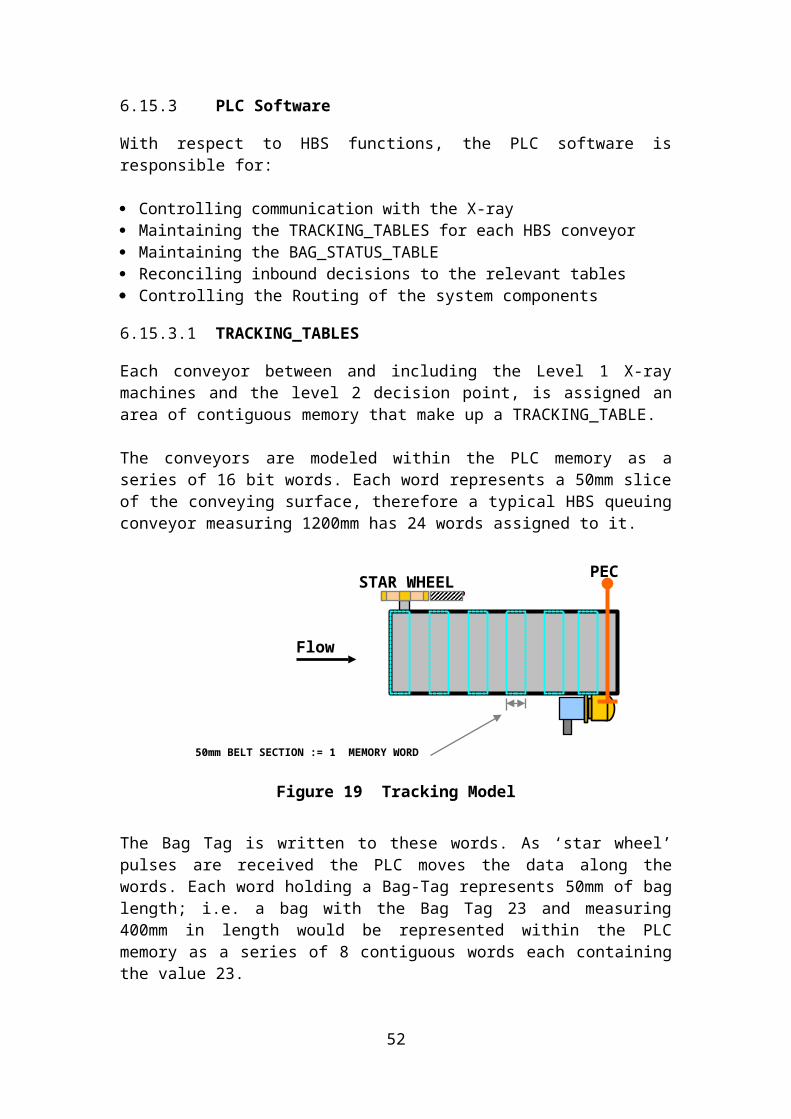
Figure 28 Check-in desk layout
52

Figure 29 Check-in desk visualization
Figure 30 Check-in desk from above
Dimensions, mm- front width, mm 1000
53

- depth, mm 800- height, mm 1250- length of foundation with construction, mm 1950
Basic elements- strut design suitable for mounting of baggage drop-off system between counters. See
reference specification to Type 22 or similar system providers;- sides from stainless steel;- frontal area – Kerrock or similar;- shelf adjacent to frontal part;- document exchange shelf – Kerrock or similar;- foundation with abrasion resistant cover, side finishing – stainless steel.
Delivery set of one check-in desk:- place for blanks, luggage tags and boarding passes – 1 set;- shelf for printer, under the table, with draw-out rack, lockable – 1 set;- fittings for computer under the table, metal, with rolls – 1 set;- electrical sockets – 6 pcs;- network socket (8P8C) - 4 pcs.;- chair for check-in agent, “OLO 11E metallic” or similar.
Devices on table:- luggage weight indicator for passengers, built on upper surface on right/left from operator – 1
set;- luggage weight indicator for operator, built on upper surface on right/left from operator – 1
set, style according to existing displays on existing counters; - pedal and/or button for weight belt conveyer LKS control;- control of marking belt conveyer LKM;- computer;- keyboard;- printer;- phone.
Other:Inside table there must be entrances and place for phone cable, second level electricity supply 220 V, 50 Hz, 1,5 kWt.
Frontal part LED lights – 1 pc.; All colours, dimensions and materials to be double checked before ordering.
Contractor must be able to provide check-in desk with above mentioned dimensions, technical description and layout. Specific details – min/max dimensions, exact height can be changed after approval from RIX.
13. RECONSTRUCTION OF PREMISES AND INSTALLATION OF CONVEYER BELT
Contractor takes full responsibility to receive necessary permits to do works. Contractor takes full responsibility for any damage done to existing systems or processes in RIX. The Bidder should preform evaluation of site during procurement. Based on the results of the site survey Bidder should guarantee the correct amount of work, dimensions and requirements of the delivered systems and installations.Any works at airport terminal should not interfere with the regular airport operations. Construction site must be protected from unauthorized entry and hidden from public observation. Area around the construction site must be clean and without obstacles for passenger flow.
54

Any installations that require interference into airport operations must be carried at night time (or other time agreed with RIX) and with guaranty that minimum one hour before airport daily operations system must be operational and tested.
14. TIME FRAME
Time frame of works can be changed only during procurement procedure.
Figure 31 Suggested time frame
Contractor must grant 5 year warranty to all the works done according this Request for proposal.
Attached: - PLC control “RixLoganL2_software.7z ; RixLoganL1_software.7z”;- “Electrical Drawings.zip”;- “Evacuation plan_2nd floor pdf”;- “lentas pārbūve ar telpām-Model.pdf”- “lentas pārbūve ar telpām-demontejamas.pdf”- “location of main power supply.pdf”- “terminal drawings”.
55