research.chem.ucr.eduresearch.chem.ucr.edu/.../documents/glovebox_2015-06b.docx · web view2.1...
TRANSCRIPT
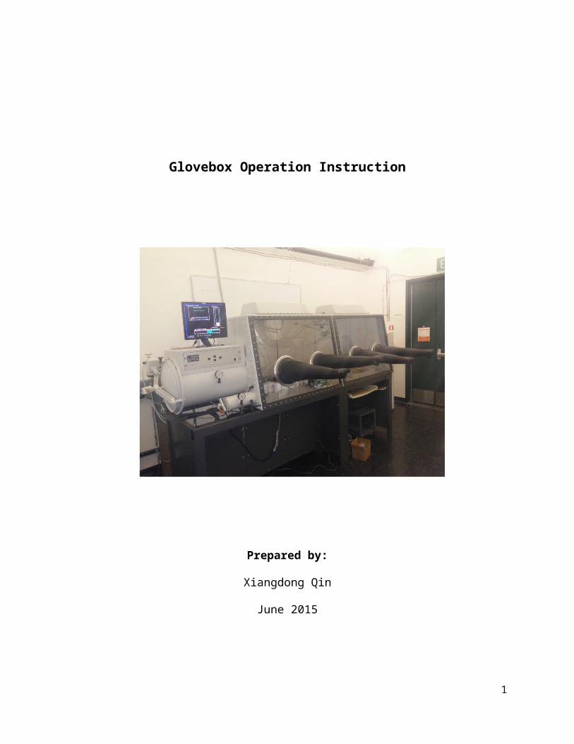
Glovebox Operation Instruction
Prepared by:
Xiangdong Qin
June 2015
1
Table of Contents
1. Introduction
1.1 Purpose and Scope
1.2 General Rules
1.3 Sample Rules
1.4 Glovebox Condition
2. Glovebox Operation (Regular User)
2.1 System Operation
2.2 Introducing Items to the Glovebox through the Antechamber
2.3 Removing Items from the Glovebox through the Antechamber
2.4 Use of Footswitch
2.5 Changing N2 Gas Cylinder
3. Glovebox Operation (Advanced User)
3.1 Pressure Control Routine
3.2 Laboratory Purge Routine
3.3 Oxygen Analyzer
3.4 Regeneration
3.5 Introducing and Using Solvents inside the Glovebox
4. Maintenance (Advanced User)
4.1 Vacuum Pump Maintenance
4.2 Glove Replacement Procedure
4.3 Solenoid Valve Servicing
4.4 Circulation Ball Valve Servicing
2
Standard Operating Procedure for Glovebox in RM 135
1. Introduction
1.1 Purpose and Scope
This manual is intended to provide the general guidelines and standard operation procedures for the use of the glovebox located in RM135. The model of the glovebox is Nexus One Series made by Vacuum Atmosphere Company. The glovebox is intended to provide a water and oxygen free environment for the handling air-sensitive samples. The procedures below are designed to ensure safe operation of the glovebox, protect the glovebox, and preserve the integrity of the samples.
1.2 General Rules
(1) Only authorized users are permitted to use the glovebox
(2) All procedures associated with safe handling of chemicals are to be strictly followed. Please refer to SOP of each chemical.
(3) Any work inside the glovebox or use of antechambers must be recorded in the logbook. Jewelry (watches, rings, bracelets, etc), can damage the gloves and must be removed. Clean gloves must be worn before inserting hands into glovebox gloves. DO NOT use any gloves which have come into contact with research materials, solvents, or other hazardous chemicals.
Aluminum foil must be placed in the work area to collect spilled samples. Avoid sharps (razors, scissors,) if possible. Authorization is required prior to sharp items being placed in the glovebox. The sharps should be clearly marked. Use of long sleeve shirts or lab coat while using the glovebox is encouraged.
1.3 Sample Rules
(1) No volatile sulfur-containing compounds or volatile phosphines are allowed inside the box. These compounds are extremely poisonous to many types of catalysts. All solid materials must be contained under inert atmosphere and powders must be properly dried to prevent the introduction of adsorbed water. A pre-sealed oxygen or moisture sensitive liquid can be stored inside the glovebox. No regular solvents are allowed into the glovebox at present either.
(2) Sample containers should be filled with an inert atmosphere before insertion, and should be capable of maintaining low levels of O2 and H2O during transport. Sample containers that have been stored cold must be allowed to warm up to room temperature before being brought into the glovebox to avoid bringing in the moisture that condenses on the container surface.
(3) Other necessary materials (Kimwipes, aluminum foil) are available inside the glovebox. All samples/chemicals must be appropriately labeled. All trash generated as part of work in the glovebox (e.g., used Kimwipes, weighing paper) must be removed upon completion of the work and is the responsibility of the user.
3
(4) The glovebox is used to store oxygen and water sensitive chemicals. Approval from Dr. Xiangdong Qin is needed before any new chemical can be stored inside.
1.4 Glovebox Condition.
The glovebox operating parameters should not to be modified. The current optimized O2 level is about 15 part per million (ppm)
2. Glovebox Operation (regular user)
This section describes the detailed operation procedures for regular users. The operating pressure of the glovebox is +1.5 to +4.5 inches of water above the outside atmosphere. The normal state of the antechambers (when not in use) is under vacuum. After completing your work, the antechambers must be left under dynamic vacuum. Do not over tighten the antechamber ports. Inspect gloves for damage prior to use. Do not work in glovebox if levels are above 20 ppm and notify the glovebox contact immediately. Every transfer and action that happens in the glovebox must be recorded in the logbook.
2.1 System Operation
The user interface only has four keys and a menu-driven control software providing simple operator input. The display prompts the user for all input and is the first place to look when in doubt of what to do in any situation.
The four keys are Function (FCT), Escape (ESC), Up-arrow, and Down-arrow.
Use the FCT key to choose the menu option indicated by the arrow on the menu. Pressing the FCT key during the normal monitor mode accesses the first option menu.
The up and down arrow keys move the menu arrow and change the value of any variable currently on the screen. The arrow keys attenuate the blower speed in the normal monitor mode.
The ESC key resets the system back to normal mode from any point in the operation. The ESC key turns off alarms during an alarm condition and quits any routine currently running.
The monitor displays the actual pressure inside the glovebox on the pressure graphic along with current oxygen level and blower speed.
2.2 Introducing Items into the Glovebox through the Antechamber
4

(1) Check the oxygen level to ensure that it is in the right range. Check the pressure on the N2 gas cylinder and record it in the logbook. If the total pressure of the N2 gas cylinder is less than 300 psi, please change to a new N2 gas cylinder following the instruction in Section 2.5. And please notify Dr. Xiangdong Qin to purchase a new bottle. The supplied N2 pressure should be around 35 Psi. The antechamber is under vacuum, and its pressure is indicated by a gauge.
(2) Press the FCT key. Use the up and down-arrow to select the AutoVac option menu. Press FCT key to access the menu.
(3) Use the up and down-arrow to select the Start Manual Refill Routine. Press FCT key. The antechamber will be filled with N2 as the pressure gauge in the antechamber indicates. The process will stop automatically once the right pressure is reached. Press the ESC key to return to the normal mode.
(4) Open the outer antechamber door. Place items onto the pull out tray. Close the door.
(5) Press the FCT key. Use the up and down-arrow to select the AutoVac option menu. Press FCT key to access the menu. Use the up and down-arrow to select the Start AutoVac Sequence. Press FCT key.
(6) The AutoVac control menu will be displayed on the monitor. The vacuum setpoint (50), pump time (5 min) and number of cycles (3) will be indicated. Press FCT key to start the sequence. It will take about 20 mins. Once the sequence is completed, it will be displayed on the monitor. Press the ESC key to return to the normal mode.
(7) Open the inner antechamber door. Move the items on the tray into the glovebox. Close the door. If the item needs to be removed from the glovebox within 10 mins, skip steps 8 and 9 and go to section 2.3 for details. Otherwise, follow step 8 and 9.
(8) Press the FCT key. Use the up and down-arrow to select the AutoVac option menu. Press FCT key to access the menu. Use the up and down-arrow to select the Start Manual Evacuation Routine. Press FCT key to start. Leave it for 5 mins. Then press the ESC key to return to the normal mode.
(9) Record the O2 level after use in the logbook.
2.3 Removing Items from the Glovebox through the Antechamber
(1) If you remove the items within 10 mins of introducing them into the glovebox, please go to step 4 directly.
(2) Ensure that the antechamber is under vacuum. Press the FCT key. Use the up and down-arrow to select the AutoVac option menu. Press FCT key to access the menu. Use the up and down-arrow to select the Start AutoVac Sequence. Press FCT key.
(3) The AutoVac control menu will be shown on the monitor. The vacuum setpoint (50), pump time (5 min) and number of cycles (3) will be displayed. Press FCT key to start the sequence. It will take about 20 mins. Once the sequence is completed, it will be displayed on the monitor. Press the ESC key to return to the normal mode.
5
(4) Open the inner antechamber door. Move the items on the tray in the antechamber. Close the inner door.
(5) Open the outer antechamber door. Remove items from the tray and close the outer door.
(6) Press the FCT key. Use the up and down-arrow to select the AutoVac option menu. Press FCT key to access the menu. Use the up and down-arrow to select the Start Manual Evacuation Routine. Press FCT key to start. Leave it for 5 mins. Then press the ESC key to return to the normal mode.
(7) Record the O2 level after use in the logbook.
2.4 Use of Footswitch
The footswitch should be used whenever the user’s hands are in or out of the glovebox. Press the right or left side of the footswitch to increase or decrease the lab pressure, respectively. The footswitch only allows hanging the pressure within the upper and lower lab pressure limits set up in the pressure control routine.
2.5 Changing N2 Gas Cylinder
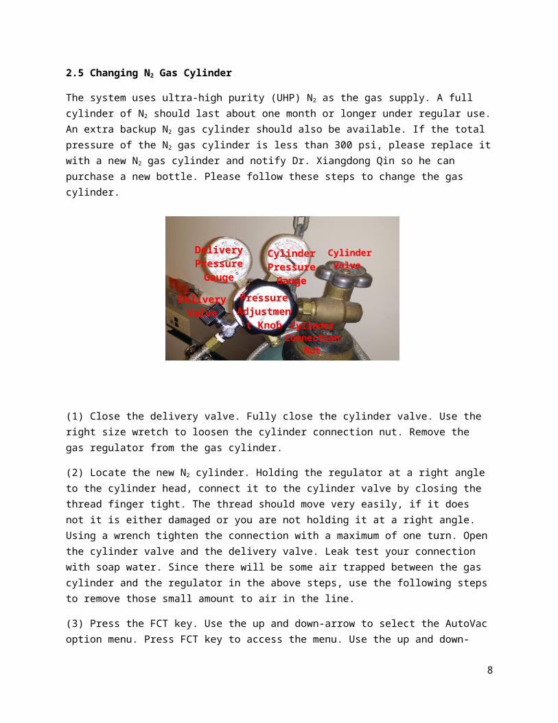
The system uses ultra-high purity (UHP) N2 as the gas supply. A full cylinder of N2 should last about one month or longer under regular use. An extra backup N2 gas cylinder should also be available. If the total pressure of the N2 gas cylinder is less than 300 psi, please replace it with a new N2 gas cylinder and notify Dr. Xiangdong Qin so he can purchase a new bottle. Please follow these steps to change the gas cylinder.
(1) Close the delivery valve. Fully close the cylinder valve. Use the right size wretch to loosen the cylinder connection nut. Remove the gas regulator from the gas cylinder.
(2) Locate the new N2 cylinder. Holding the regulator at a right angle to the cylinder head, connect it to the cylinder valve by closing the thread finger tight. The thread should move very easily, if it does not it is either damaged or you are not holding it at a right angle. Using a wrench tighten the connection with a maximum of one turn. Open the cylinder valve and the delivery valve. Leak test your connection with soap water. Since there will be some air trapped between the gas cylinder and the regulator in the above steps, use the following steps to remove those small amount to air in the line.
6
Cylinder Connection Nut
Delivery Valve
Delivery Pressure Gauge
Cylinder Pressure Gauge
Pressure Adjustment
Knob
Cylinder Valve
(3) Press the FCT key. Use the up and down-arrow to select the AutoVac option menu. Press FCT key to access the menu. Use the up and down-arrow to select the Start Manual Evacuation Routine. Press FCT key to start. Leave it for 5 mins. Then press the ESC key to return to the normal mode.
(4) Press the FCT key. Use the up and down-arrow to select the AutoVac option menu. Press FCT key to access the menu. Use the up and down-arrow to select the Start Manual Refill Routine. Press FCT key. The antechamber will be filled with N2 as the pressure gauge in the antechamber indicates. The process will stop automatically once the right pressure is reached. Press the ESC key to return to the normal mode.
(5) Press the FCT key. Use the up and down-arrow to select the AutoVac option menu. Press FCT key to access the menu. Use the up and down-arrow to select the Start Manual Evacuation Routine. Press FCT key to start. Leave it for 5 mins. Then press the ESC key to return to the normal mode.
(6) The new N2 gas cylinder is ready to use.
3. Glovebox Operation (Advanced User)
This section describes the detailed operation procedures for advanced users. Do not proceed if you are not approved by Dr. Xiangdong Qin as an advanced user.
3.1 Pressure Control Routine
The pressure control routine allows the user to set the high and low pressure limits for the glovebox and the safety high and low pressure limits. The monitor displays the pressure in the horizontal bar graphic with the operating pressure limits in an additional bar graphic. The safe operating zone is the green zone and the “out of bounds” zone is red.
The safety limits are the absolute limits the glovebox should never actually reach since the controller shuts down all function during any routine to correct overpressure or underpressure conditions. The safety limits should be conservatively set beyond the operating limits. The current safety upper limit is 6.0. The low and high pressure limit is 1.5 and 4.5, respectively.
Steps to change the pressure limit,
(1) Press the FCT key.
(2) Use the up-and-down arrow to select the Lab Pressure Menu. Press the FCT key.
(3) Use the up-and-down arrow to select the pressure limit (pressure limit or safety limit) you would like to change. Press the FCT key to access each pressure setting. Press FCT one more time to select either upper or lower limit. Use the up-and-down arrow to set the desired pressure limit.
(4) Press ESC to return to the normal mode.
3.2 Laboratory Purge Routine
7
The purge routine allows the user to purge the glovebox with inert gas to displace the glovebox’s existing atmosphere. This routine makes it easy to establish an atmosphere during initial startup and to clean up after a repair or unintentional exposure.
(1) Press the FCT key.
(2) Use the up-and-down arrow to select the Purge Option. Press FCT key to access the menu.
(3) Use the Use the up-and-down arrow to select the Purge Time Option. Press FCT key to access the option.
(4) Press FCT key to select parameter from hours to minutes as indicated by green characters.
(5) Use the up-and-down arrow to set the time.
(6) Press ESC to return to the main menu.
(7) Press the FCT key. Use the up-and-down arrow to select the Purge Option. Press FCT key to access the menu.
(8) Use the up-and-down arrow to select the Start Purge Routine option. Press FCT to start the purge.
(9) After the purge is finished, press the ESC key to return to the main menu.
3.3 Oxygen Analyzer
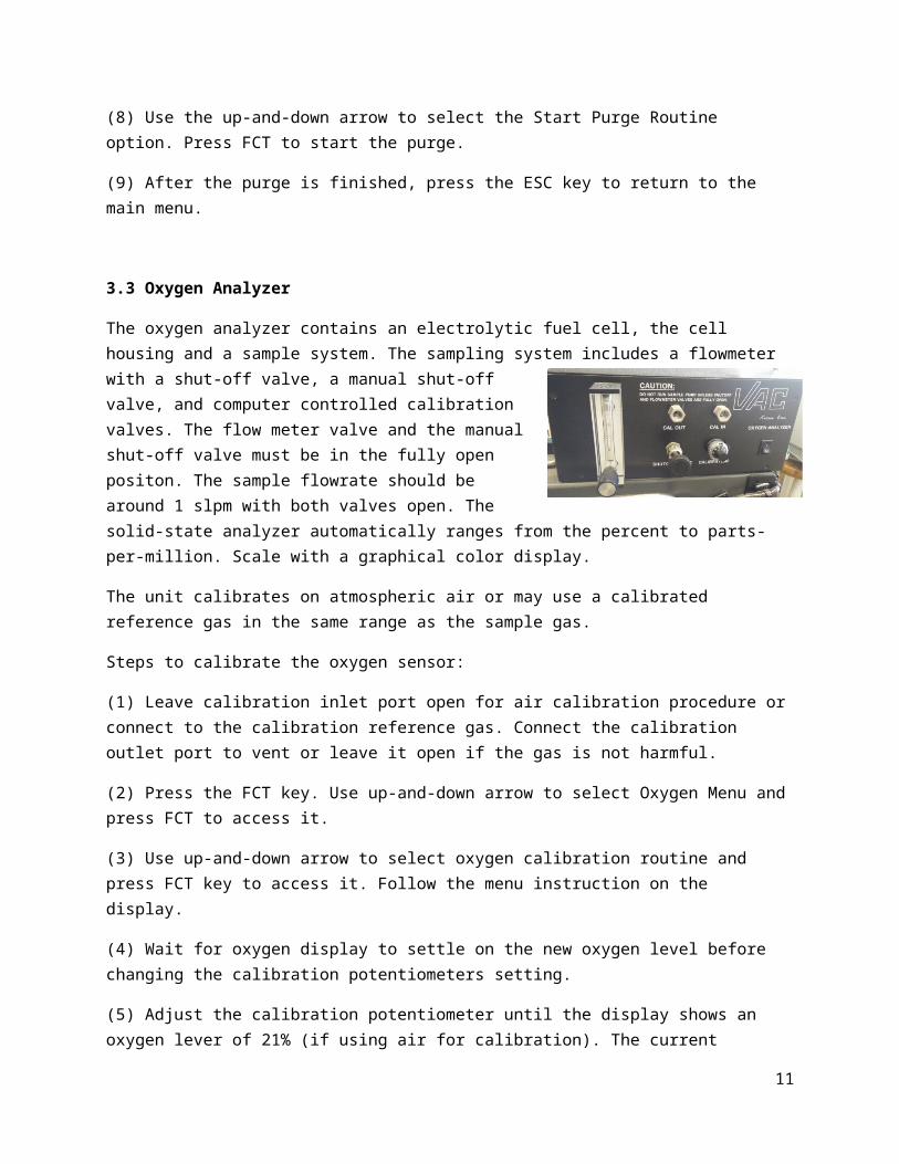
The oxygen analyzer contains an electrolytic fuel cell, the cell housing and a sample system. The sampling system includes a flowmeter with a shut-off valve, a manual shut-off valve, and computer controlled calibration valves. The flow meter valve and the manual shut-off valve must be in the fully open positon. The sample flowrate should be around 1 slpm with both valves open. The solid-state analyzer automatically ranges from the percent to parts-per-million. Scale with a graphical color display.
The unit calibrates on atmospheric air or may use a calibrated reference gas in the same range as the sample gas.
Steps to calibrate the oxygen sensor:
(1) Leave calibration inlet port open for air calibration procedure or connect to the calibration reference gas. Connect the calibration outlet port to vent or leave it open if the gas is not harmful.
(2) Press the FCT key. Use up-and-down arrow to select Oxygen Menu and press FCT to access it.
(3) Use up-and-down arrow to select oxygen calibration routine and press FCT key to access it. Follow the menu instruction on the display.
8

(4) Wait for oxygen display to settle on the new oxygen level before changing the calibration potentiometers setting.
(5) Adjust the calibration potentiometer until the display shows an oxygen lever of 21% (if using air for calibration). The current setting on the potentiometer is 9.40. Please note that air calibration depletes the fuel cell, so do not calibrate the unit with air for an extended period of time.
(6) Press ESC to quite the calibration routine.
3.4 Blower speed control
The circulation blower speed control provides available speed adjustment from 0 to 100%. Blower speed should be set at eh minimum speed need to keep the inter atmosphere at the desired purity level since excessive speed increases the glovebox atmosphere temperature and blower wear. In the normal mode, the up-and-down arrow keys increase and decrease the blower speed, receptively.
Since the oxygen sensor is installed in this system, currently the blower speed is controlled by SMART blower speed control. The option is activated in the Oxygen Menu by following the instruction on the screen. The SMART mode automatically adjusts the blower speed to maintain the oxygen level in the glovebox with the minimum blower speed.
3.4 Regeneration
The purifiers have a limit oxygen and moisture removal capacity depending on the quality of the catalyst material. The regeneration cycle restores the purifiers during the regeneration cycle. The lab must have an inert atmosphere of less than 200 ppm of oxygen before purifier regeneration or contamination may occur during the cycle.
All regeneration operations are available through the DRI-TRAIN Control menu. The user can start or stop a regeneration cycle using the menu instruction on the display. The display shows the current mode of the regeneration and the remaining time of the cycle.
The cycle requires nitrogen with 3-5% hydrogen at approximately 35 psi. The system automatically shuts down the regeneration cycle if the gas pressure falls below 30 psi. Regeneration will take 24 hours to finish. And it will consume about 1/3 of a full bottle of regeneration gas.
Please note that the two circulation valves (located in the back side and marked as circulation valve) must be closed during regeneration cycle.
3.5 Introducing and Using Solvents inside the Glovebox
In general, using solvents inside the glovebox is not recommended under the current conditions. This requires approval from Dr. Xiangdong Qin and special training.
9
Non-protic solvents and volatile solids are allowed. In general, liquids should be anhydrous (either by pre-treatment or purchased anhydrous) for use in the glovebox. The use of carbonyl-containing solvents (e.g. 2-propanone) is STRONGLY DISCOURAGED. Solvent containers need to be very well sealed and taped up before bringing into the glovebox antechamber to avoid solvent leakage into the pump and to minimize shattered glass in case of a broken container. Solvent bottles must remain closed when the glovebox is not in use. Any solvents brought into the glovebox need to be removed and properly disposed of at the end of the experimental run.
(1) Follow the same procedures of transferring samples from antechamber into the glovebox. However, manually control the pump and refill steps. When pumping, do not let the pressure inside the antechamber get too low (negative). During refill, only refill to close to atmosphere in the first few cycles.
(2) Move the solvent into the glovebox, close the inner door. Evacuate the antechamber.
(3) Turn off the circulation fans and close both circulation valves.
(4) Open solvents and perform work. Keep a close watch on the O2 level. The O2 level will increase.
(5) Upon completion of the solvent work (or after 30 minutes, whichever comes first), purge the glovebox for at least 10 minutes by using the purge menu.
(6) Stop purging and open the circulation valves. Turn on the circulation fan.
4. Maintenance (Advanced User)
This section provides a the detailed maintenance guide for advanced users. Do not proceed if you are not approved by Dr. Xiangdong Qin as an advanced user.
4.1 Vacuum Pump Maintenance
Replace the oil in the pump after each regeneration of the purifier due to moisture buildup. Use the following procedure to change the pump oil.
(1) Wear proper PPE (gloves, safety goggles and lab coat). Isolate the mechanical pump from the glovebox system. Stop the pump and remove all the connection. Wait for 20 mins, the pump oil may still be hot.
(2) Lift the pump on the moving cart (stored in RM 135). Put the waste oil bucket below the pump. Remove the top screw. Slowly unscrew the bottom screw and leak all the oil into the bucket.
(3) Screw the bottom screw again and add 0.5 L of clean oil. Rinse the pump by running it for 5 mins. Stop the pump and drain the oil. Multiple rinses may be needed if the pump is too dirty.
(4) Fill the pump with clean oil. Do not overfill. Tight all the screws and connect the pump back to the glovebox system. Start the pump.
(5) Put the used oil in the waste bottle with proper chemical waste tag.
10
4.2 Glove Replacement Procedure
(1) This procedure assumes an inert atmosphere has been established, which should be maintain while changing the glove. Having your hand inside the glovebox glove, pull the cover through the glove port until the spring-loaded nylon clips latch onto the outside edge of the glove port. The O-ring surface should rest flat against the inside edge of the glove port. Tighten knob securely.
(2) The damaged glove may now be removed by removing the clamp and O-ring.
(3) Install the new glove by folding the glove's cuff inside out approximately 2 inches.
(4) Place glove into glove port/glovebox and stretch cuff onto glove port flange. The bead in the cuff should be positioned in the inner groove closest to the glovebox.
(5) Adjust glove so that thumb is pointed in the correct direction.
(6) Stretch O-ring over glove and into the outer groove. Make sure there are no wrinkles, especially under the O-ring.
(7) Cover O-ring with black plastic electrical tape.
(8) Install clamp over O-ring.
New glove requires pumping of air prior to removing glove port cover as noted herein:
(a) Increase and maintain positive pressure in glovebox at approx. +4” water column.
(b) Open the valve connected to the cover to pump down the volume between the cover and the glove. Close valve.
(c) Loosen cover to allow glove to fill with inert gas from glovebox. Once glove is pressurized, tighten cover again.
(d) Repeat above process two or three times before removing cover and placing it back in the glovebox.
11
4.3 Solenoid Valve Servicing
Eventually one or more of the solenoid valves in the system can become clogged, worn out, or damaged. At this time the valve(s) will need to be cleaned or replaced. When replacing valves, the valve body should not be replaced. This part should remain connected to the valve manifold. All of the removable parts (not including the solenoid) should be replaced.
It should be noted that some valves are connected directly to the glovebox. Disassembly of any of these valves will create a leak in the glovebox. Some valves are connected to the purifiers. Disassembling one of these valves will expose the purifiers to air. Take appropriate precautions when servicing any of the solenoid valves.
(1) To prevent any contamination of the glovebox atmosphere, raise the glovebox pressure to +4.5 and +5 inches. Shut off the power, inert gas, and forming gas supply to the system. Isolate the glovebox by closing the circulation valves.
(2) Locate the valve that needs to be serviced. The valves can be identified by a label on the black solenoid wire. To prevent any contamination of the glovebox atmosphere, have the replacement valve ready to install as soon as the old valve and O-ring have been removed. As an alternative to this, strong tape (such as duct tape) may be used to cover the top of the valve body. This will prevent the positive pressure in the glovebox from leaking out rapidly.
(3) Using a small, flat blade screwdriver, remove the red cap on the top of the solenoid.
(4) Press the body of the solenoid down towards the valve body (it is spring loaded). Insert the screwdriver into the ‘notch’ at the base of the retainer plate (nearest the wire connections) and pry the retainer plate ‘foreword’, away from the wire connections. It should come off.
(5) Pull the solenoid off of the valve. There is no need to disconnect the wires. Remove the spring washer and store it with the red cap and retainer plate.
(6) Unscrew the plunger tube from the valve body. It is easiest to do this using a 1-inch deep socket and ratchet, however it is possible to use a crescent wrench or 1 inch open-end wrench. Break the plunger tube loose with the socket, then unscrew it the rest of the way by hand.
(7) Remove the plunger tube and plunger assembly (see figure below, Items 1 & 8) as one unit.
(8) Remove the housing seal O-ring (Item 7).
(9) Clean out any debris or contamination in the valve body.
(10) Examine the O-ring and the rubber seal on the end of the plunger assembly for damage. The O-ring cross section should be round without any nicks. Replace it if it is flattened or cut.
(11) The rubber seal on the plunger assembly should be flush with the edge of the plunger. If the seal is swollen past the plunger edge or appears otherwise damaged, replace it.
12

(12) The plunger should be fairly smooth with no deep scratches or ‘notching’. If the plunger appears to have a ‘stepped notch’ around its circumference where the part of the plunger nearest the seal appears to have a larger diameter than other end, replace it.
(13) If you noticed none of these signs and the valve components appear similar to those in the following picture, clean off any dust or contamination and reassemble the valve.
(14) Reconnect the inert and regeneration gas supplies. Turn the system power back on.
NOTE: Depending upon which valves were serviced, the purifiers or circulation plumbing may have been exposed to a small amount of air. It is recommended to begin purging the glovebox at the time circulation is started. Stop the purge after a few minutes if no oxygen rise is indicated.
13

4.4 Circulation Ball Valve Servicing
The system uses ball valves for purifier circulation / glovebox isolation. These valves are 1-1/2 inch flange diameter. Eventually one or more of the ball valves may become worn out or damaged. At this time the valve will have to be rebuilt or replaced. Please be noted that this operation will expose the glovebox and the purifier to air. After completion, you will need to purge out the glovebox and regenerate the purifier.
(1) Turn off the blower and shut off power to the system.
(2) Place the valve handle (on the valve to be removed) so that the valve is in the open position. This will prevent the valve ball from falling out of the valve body during disassembly.
(3) Remove the valve handle. Remove the three sets of fastening hardware that hold the main valve body between the flange and the glovebox.
(4) Remove the plumbing from the valve. Be careful not to lose the O-ring.
(5) Lift the valve off of the mounting studs. Rotate the valve stem so that the valve is in the closed position. Press the ball so that valve seat and the ball come out the other side of the valve body.
(6) Remove the other valve seat and the valve to flange O-ring seals from the valve body.
(7) Push the valve stem from the outside of the valve until it is completely out of the valve body.
(8) Remove the stem O-ring seals and the plastic washer from the valve stem.
(9) Thoroughly clean the valve stem, valve ball, and the inside of the valve body.
(10) Lightly lubricate the new O-ring seals and valve seats with vacuum grease.
(11) Install the stem O-ring seals and the plastic washer on the valve stem.
(12) Install the valve stem into the valve body. Be careful not to let the plastic washer get pinched between the valve body and the stem flange.
(13) Install one of the valve seats into one side of the valve body. The beveled side should face the inside of the valve body and seat against the ball.
(14) Install the valve ball into the valve body, and then install the second valve seat.
(15) Install the valve-to-flange O-ring seals.
(16) Replace the valve onto its mounting studs. You may need to use a little extra vacuum grease on the valve-to-flange O-rings to keep them from falling out of the valve body during installation.
(17) Replace the plumbing fastening hardware, and then tighten it. Replace the valve handle.
(18) Close the circulation valves.
(19) Purge the glovebox to establish an inert atmosphere.
14
(20) Once the glovebox has been purged below 200 ppm oxygen, start regeneration.
Reference: 1. Glovebox SOP from http://mrcat.iit.edu/ 2. VAC Glovebox manual
15

User name Date and time N2 cylinder pressure (Psi)
Initial O2 level (ppm)
Afterward O2
level (ppm)New chemical
used?
16