video conference exercises 2014
TRANSCRIPT

8/10/2019 Video Conference Exercises 2014
http://slidepdf.com/reader/full/video-conference-exercises-2014 1/12
TST2601VIDEO CONFERENCE EXERCISES 2014
1
VIDEO CONFERENCE EXERCISES
SECTIONAL PROPERTIES, SHEAR FORCE AND BENDING MOMENT
1. The figure below shows a built up section. Calculate the following with XX and YY as
reference point.
a. The position of the centroid of the section.
b. The second moment of area about horizontal and vertical axis (Ixx and Iyy).
c. The radius of gyration, rx and ry.
d. The elastic section modulus.
e. The plastic section modulus.
SOLUTION
(a)

8/10/2019 Video Conference Exercises 2014
http://slidepdf.com/reader/full/video-conference-exercises-2014 2/12
TST2601VIDEO CONFERENCE EXERCISES 2014
2
44
2323
44
2323
2
2
32.10033.100320444806333.28583325930810000
)7.1945(700701012/1)57.19(12001012012/1
32.27833.278320484286333.58334945081440000
)57.39(700107012/1)7.3960(12001201012/1
)(
7.191900
)45(700)5(1200
7.391900
)5(700)60(1200
19007001200
1070)12010(
cmmm
x x x x I
cmmm
x x x x I
Ae I I
b
mm x
mm y
mm
x x A
YY
XX
GG XX
(c)
mm A
I r
mm A
I r
YY y
XX x
78.2291900
100320433
03.1211900
27832043
(d)
341006.7017.39
278320433mm x
y
I Z XX
ex
(e)
362250
45125112516000
5.47)9510(5.7)1510(20)1080(
1510
150
80095010
108002
1900
)(10)10(802/1
mm Z
Z
x x x Zp
mm P
P
P
P A
p
p

8/10/2019 Video Conference Exercises 2014
http://slidepdf.com/reader/full/video-conference-exercises-2014 3/12
TST2601VIDEO CONFERENCE EXERCISES 2014
3
2. The figure below shows a built-up section. Calculate the following with XX and YY as
reference point.
(a) The position of the centroid of the section
(b) The second moment of area about horizontal axis (Ixx)
(c) The radius of gyration, r x
(d) The elastic section modulus.
SOLUTION
(a)
marksmmmark x
marksmmmark y
marksmm
marks x x x A
236.4012.4743
33.338.125633.334000502000
221.3112.4743
67.468.125667.464000102000
22.47438.125640002000
24
4080100
2
120100
2
2
Y
Y
X
m
40mm
100mm
100mm
X20mm
Ф40mm
8/10/2019 Video Conference Exercises 2014
http://slidepdf.com/reader/full/video-conference-exercises-2014 4/12
TST2601VIDEO CONFERENCE EXERCISES 2014
4
(b)
4
24
23
23
2
859.29169.29185938.3003891256804.95604622.14222222.89972867.66666
]21.3167.468.125664
40[21.3167.464000
36
801001021.312000
12
20100
cmmm
I
Ae I I
xx
GG xx
(c)
mm A
I r xx x 81.24
2.4743
69.2918593
(d)
37.9351421.31
69.2918593mm
y
I Z xx
ex
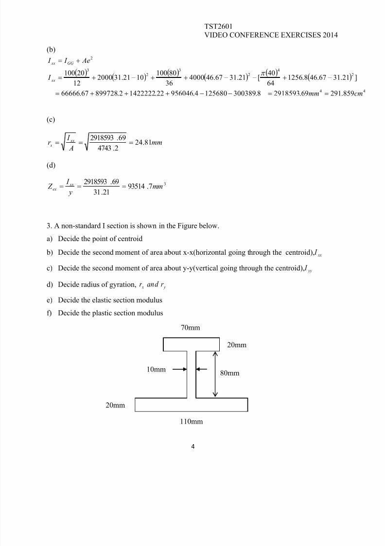
3. A non-standard I section is shown in the Figure below.
a) Decide the point of centroid
b) Decide the second moment of area about x-x(horizontal going through the centroid), xx I
c) Decide the second moment of area about y-y(vertical going through the centroid), yy I
d)
Decide radius of gyration, y x r and r
e) Decide the elastic section modulus
f) Decide the plastic section modulus
70mm
20mm
20mm
10mm
110mm
80mm
8/10/2019 Video Conference Exercises 2014
http://slidepdf.com/reader/full/video-conference-exercises-2014 5/12
TST2601VIDEO CONFERENCE EXERCISES 2014
5
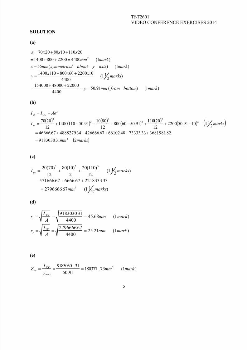
SOLUTION
(a)
)1()(91.504400
2200048000154000
)2
11(4400
102200608001101400
)1()(55)1(440022008001400
2011010802070
2
mark bottom frommm y
marks x x x
y
mark axis yabout l symmetricamm xmark mm
x x x A
(b)
marksmm
marks I
Ae I I
xx
GG xx
231.9183030
82.368198133.7333348.6610267.42666634.488827967.46666
2141091.502200122011091.5060800
12801091.501101400
122070
4
2
3
2
3
2
3
2
(c)
)2
11(67.2796666
33.221833367.666667.571666
)2
11(12
)110(20
12
)10(80
12
)70(20
4
333
marksmm
marks I yy
(d)
)1(21.254400
67.2796666
)1(68.454400
31.9183030
mark mm A
I r
mark mm A
I r
YY y
XX x
(e)
)1(73.18037791.50
31.9183030 3
ma x
mark mm y
I Z XX
ex
8/10/2019 Video Conference Exercises 2014
http://slidepdf.com/reader/full/video-conference-exercises-2014 6/12
TST2601VIDEO CONFERENCE EXERCISES 2014
6
(f)
)1(1800001260003200022000
)2(9020704010801020110)(.
int,20modint:
3 mark mm
marks x x x x x x x Zparea
totatheof half is pothisat areathebottom frommm yat isulus plasticof Po Note
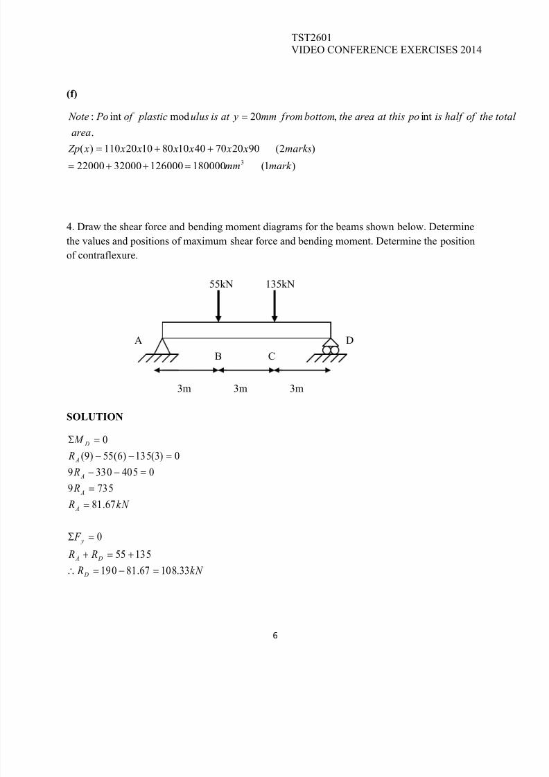
4. Draw the shear force and bending moment diagrams for the beams shown below. Determine
the values and positions of maximum shear force and bending moment. Determine the position
of contraflexure.
SOLUTION
kN R
R R
F
kN R
R
R
R
M
D
D A
y
A
A
A
A
D
33.10867.81190
13555
0
67.81
7359
04053309
0)3(135)6(55)9(
0
3m 3m 3m
135kN55kN
B
A D
C
8/10/2019 Video Conference Exercises 2014
http://slidepdf.com/reader/full/video-conference-exercises-2014 7/12
TST2601VIDEO CONFERENCE EXERCISES 2014
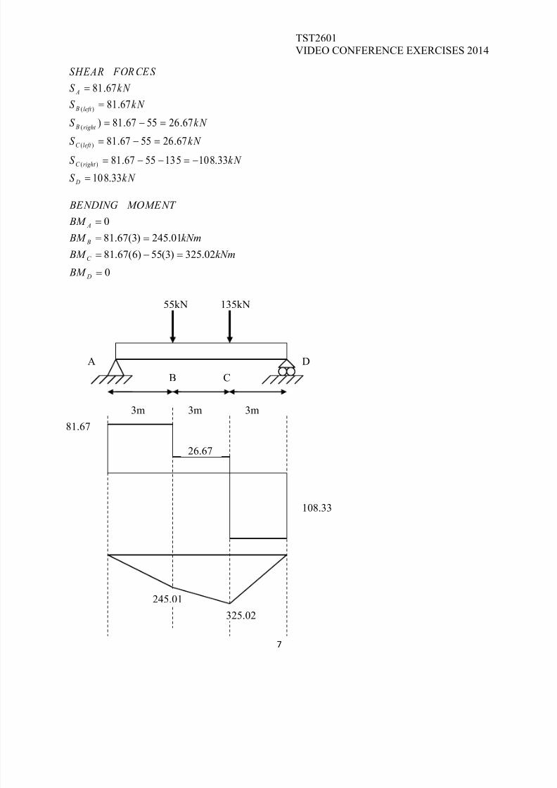
7
kN S
kN S
kN S
kN S
kN S
kN S
FORCES SHEAR
D
right C
left C
right B
left B
A
33.108
33.1081355567.81
67.265567.81
67.265567.81)
67.81
67.81
)(
)(
(
)(
0
02.325)3(55)6(67.81
01.245)3(67.81
0
D
C
B
A
BM
kNm BM
kNm BM
BM
MOMENT BENDING
3m 3m 3m
135kN55kN
B
A D
C
81.67
26.67
108.33
245.01
325.02

8/10/2019 Video Conference Exercises 2014
http://slidepdf.com/reader/full/video-conference-exercises-2014 8/12
TST2601VIDEO CONFERENCE EXERCISES 2014
8
Maximum shear force = 108.33 kN at D.
Maximum bending moment = 325.02 kNm at C
There is no point of contraflexure.
5. Draw the shear force and bending moment diagrams for the beam shown below. Determine
the values and positions of maximum shear force and bending moment. Determine position/s of
contraflexure.
SOLUTION
kN R
R R
F
kN R
R
R R
M
D
D A
y
A
A
A
A
D
11.24189.203445
445180265
0
89.203
18359
0245159090245)6(265)9(
0
8/10/2019 Video Conference Exercises 2014
http://slidepdf.com/reader/full/video-conference-exercises-2014 9/12
TST2601VIDEO CONFERENCE EXERCISES 2014
9
kN right S
kN left S kN S
kN right S
kN left S
kN S
FORCES SHEAR
D
D
C
B
B
A
9011.241)3(3026589.203)(
11.151)3(3026589.203)(11.6126589.203
11.6126589.203)(
89.203)(
89.203
0
99.1342
)3(30245)6(265)9(89.203
34.183245)3(265)6(89.203
34.428)3(265)6(89.203
67.611)3(89.203
0
2
E
D
C
B
A
BM
kNm BM
kNmright BMC
kNmleft BM
kNm BM
BM
MOMENT BENDING
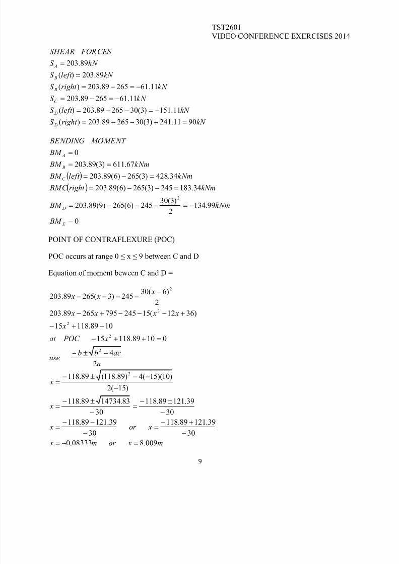
POINT OF CONTRAFLEXURE (POC)
POC occurs at range 0 ≤ x ≤ 9 between C and D
Equation of moment beween C and D =
m xor m x
xor x
x
x
a
acbbuse
x POC at
x
x x x x
x x x
009.808333.0
30
39.12189.118
30
39.12189.118
30
39.12189.118
30
83.1473489.118
)15(2
)10)(15(4)89.118(89.118
2
4
01089.11815
1089.11815
)3612(1524579526589.203
2
)6(30245)3(26589.203
2
2
2
2
2
2
8/10/2019 Video Conference Exercises 2014
http://slidepdf.com/reader/full/video-conference-exercises-2014 10/12
TST2601VIDEO CONFERENCE EXERCISES 2014
10
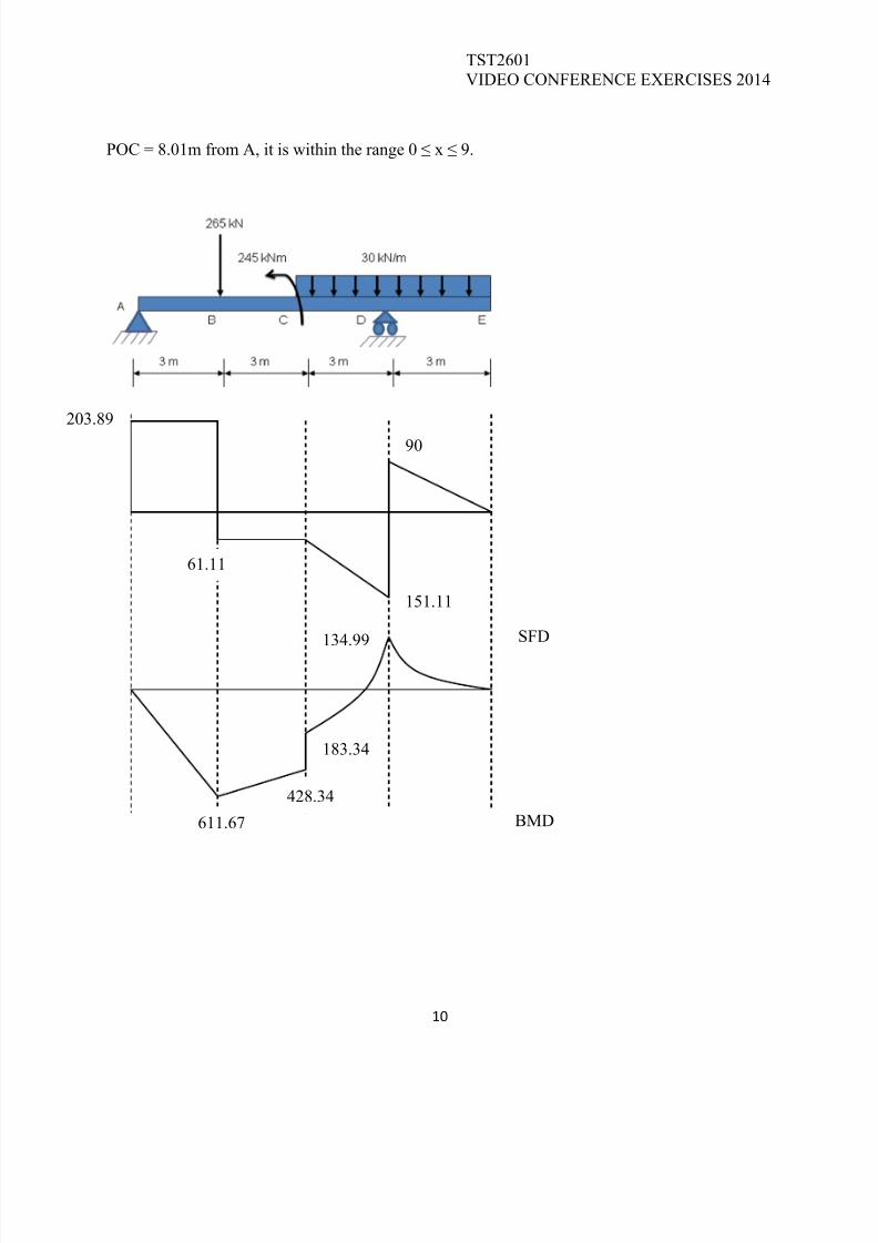
POC = 8.01m from A, it is within the range 0 ≤ x ≤ 9.
SFD
BMD
203.89
90
151.11
61.11
134.99
183.34
428.34
611.67
8/10/2019 Video Conference Exercises 2014
http://slidepdf.com/reader/full/video-conference-exercises-2014 11/12
TST2601VIDEO CONFERENCE EXERCISES 2014
11
6. A cantilever beam 2 m long has a rectangular cross-section 50 mm wide and 150 mm deep. It
carries a uniformly distributed load of 5kN/m over the whole span and in addition to this an
axially applied compressive force of 3kN.
(a) Calculate the maximum resultant direct stress in the beam, and
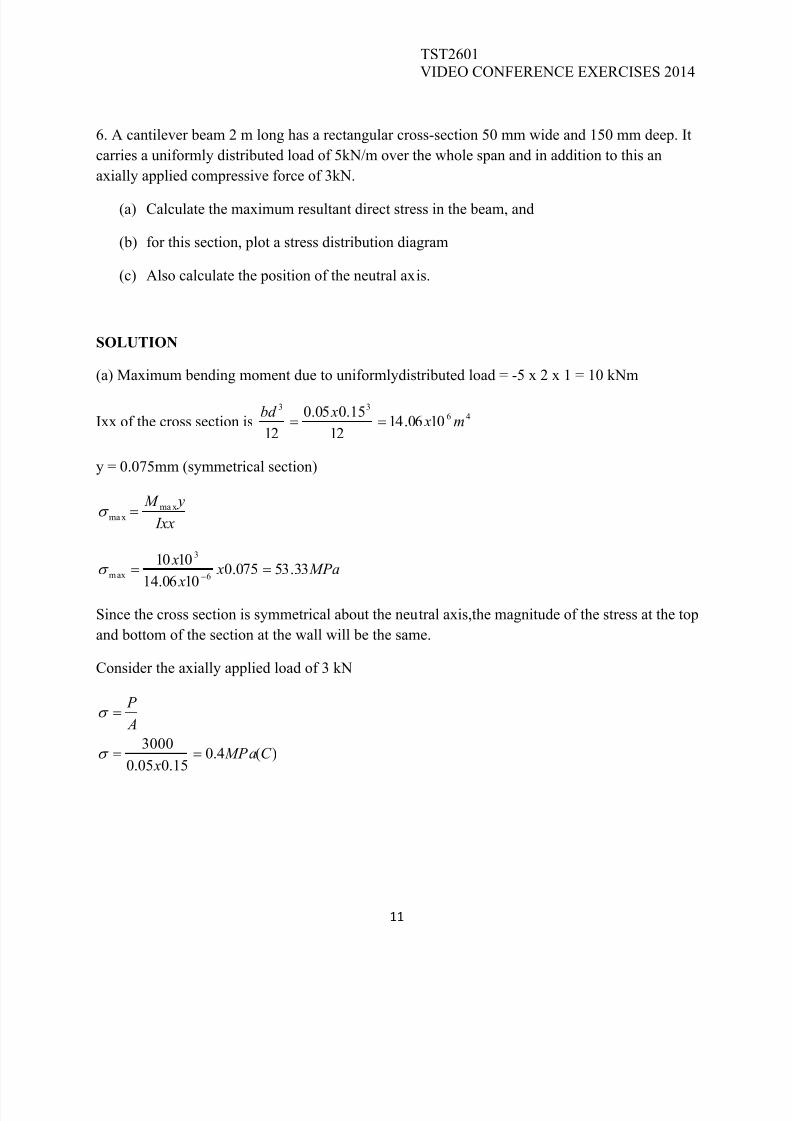
(b) for this section, plot a stress distribution diagram
(c) Also calculate the position of the neutral axis.
SOLUTION
(a) Maximum bending moment due to uniformlydistributed load = -5 x 2 x 1 = 10 kNm
Ixx of the cross section is46
33
1006.1412
15.005.0
12m x
xbd
y = 0.075mm (symmetrical section)
Ixx
y M maxmax
MPa x
x
x33.53075.0
1006.14
10106
3
max
Since the cross section is symmetrical about the neutral axis,the magnitude of the stress at the top
and bottom of the section at the wall will be the same.
Consider the axially applied load of 3 kN
)(4.015.005.0
3000C MPa
x
A
P
8/10/2019 Video Conference Exercises 2014
http://slidepdf.com/reader/full/video-conference-exercises-2014 12/12
TST2601VIDEO CONFERENCE EXERCISES 2014
12
(b)
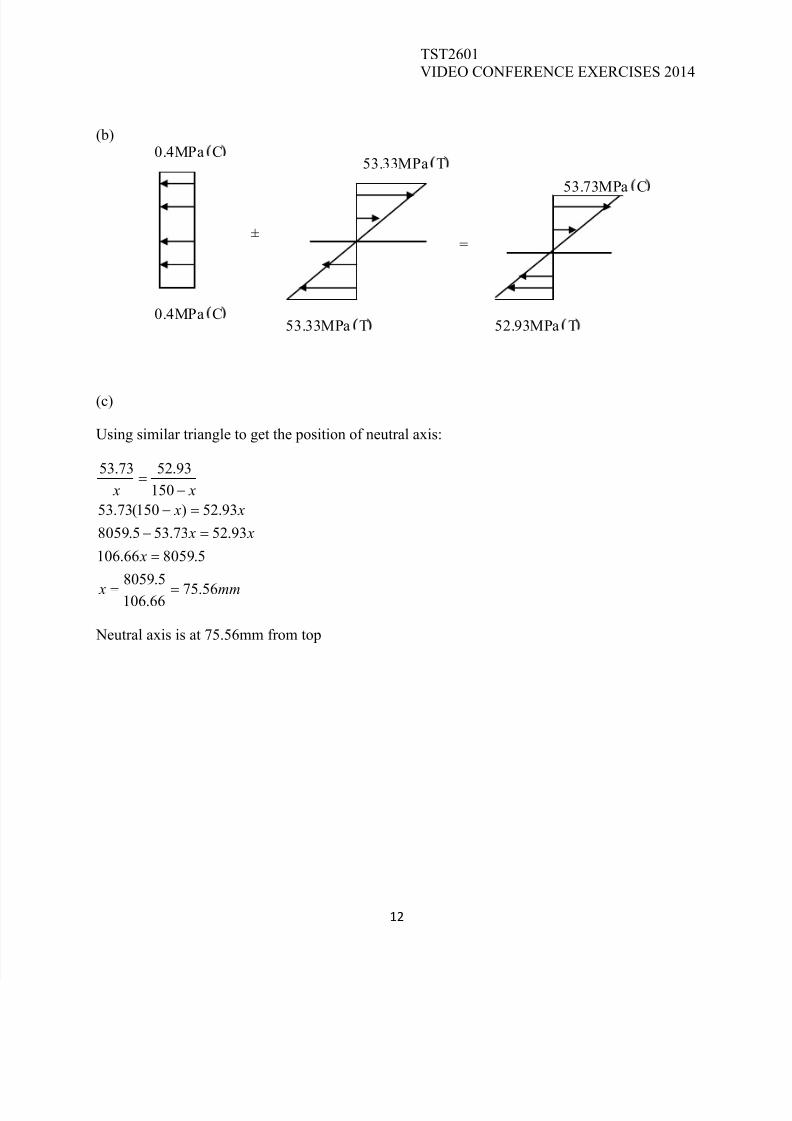
(c)
Using similar triangle to get the position of neutral axis:
mm x
x
x x
x x
x x
56.7566.106
5.8059
5.805966.106
93.5273.535.8059
93.52)150(73.53
150
93.5273.53
Neutral axis is at 75.56mm from top
±=
0.4MPa C
0.4MPa C
53.33MPa T
53.33MPa T 52.93MPa T
53.73MPa C