vibration theory fundamentals -...
TRANSCRIPT

1
1.1 INTRODUCTIONMechanical vibrating systems consist of elements such as a spring for storing potential energy,mass and inertia for kinetic energy, and damper for dissipating mechanical energy. The vibrationprocess alternatively converts energy between its potential and kinetic forms. In its generalsense the vibration is a periodic motion that repeats itself in all its details after a certaininterval of time, called the period of vibration. Some energy must be replaced in each cycle ofvibration from an external source to maintain the vibration.
In a linear spring the change in length is proportional to the force acting along its length,the constant of proportionality referred to as the spring’s flexibility, which is the reciprocal ofits stiffness. The ideal spring has no mass, and so the forces acting at its opposite ends areequal and opposite. A mass is a rigid body; so its acceleration, according to Newton’s secondlaw of motion, is proportional to the force acting on the mass. In a viscous damper the appliedforce is proportional to the relative velocity of its connecting points. The damping coefficientprovides the proportionality constant, and is the characteristic parameter of the damper. Theideal damper also is massless, and so the force at one end is equal and opposite to the force atthe other end.
Besides translational motion, a vibrating system may execute rotational motion. Theelements of a mechanical system executing pure rotation of the parts are analogous to theelements executing pure translation. In a rotational system inertia stores kinetic energy, whilestiffness and damping parameters are defined with reference to angular rotation and velocity.The analogy between translational and rotational motion of a vibrating body carries on to themathematical equations describing the motion of the system; force used in linear motion isreplaced by torque for rotational motion.
A plot of the linear displacement, or angular rotation, against time may be a complicatedcurve. The simplest kind of periodic motion is a harmonic motion, with the displacementexpressed as a harmonic function of time t and angular velocity ω, also referred to as thecircular frequency, and is measured in radians per second. The maximum value of thedisplacement, x0, is called the amplitude of vibration. The period of vibration, T, measured inseconds, is the reciprocal of the frequency of vibration, f, measured in cycles per second. Therelation between ω, f and T are as follows. A full cycle of vibration takes place when ωt haspassed through 360°, or 2π radians. Then the sine function resumes its previous path. Thus,when ωt = 2π, the time interval t is equal to the period T, or T = 2π/ω seconds. Since f is thereciprocal of T, f = ω/2π cycles per second. For reciprocating machinery the frequency is oftenexpressed as cycles per minute, so f = 30ω/π. In a harmonic motion displacement is given by
Vibration Theory Fundamentals 1
C-9\N-MACHINE\MAC1-1.PM5 NEW
2 Reciprocating Machinery Dynamics
x = x0 sin (ωt). Velocity is determined by differentiation with respect to time, so dx/dt = x0ω cos(ωt). Thus, velocity is also harmonic, with a maximum value of x0ω. Acceleration is given bythe second derivative of x with respect to time t:
d2x/dt2 = – x0ω2 sin (ωt) (1.1)
also harmonic, with a maximum value of x0ω2.A vibrating system is said to have one degree of freedom if its geometrical position can
be expressed at any instant in time by one number only. For example, a piston moving in acylinder can be specified by giving the distance from the cylinder end, thus classifying it as asingle degree of freedom system. Another example is a crankshaft in rigid bearings; the systemis fully described by the angle between any one crank and the vertical plane. In general, if ittakes n numbers to specify the position of a mechanical system, the system has n degrees offreedom. A disk moving in its plane without restraint has three degrees of freedom: the x andy displacements of its center of gravity and the angle of rotation about the center of its gravity.A circular disk rolling down an inclined plane has only one degree of freedom; if it partly slidesand rolls, it has two degrees of freedom, one of translation and one of rolling. A rigid bodymoving freely in space has six degrees of freedom, three of translations and three of rotation.Thus, it takes six coordinates to express its position, usually denoted as x, y, z, θ, ϕ and ψ.
A single degree of freedom system is not necessarily a simple one. For example, a 12-cylinder gas engine with a rigid crankshaft and a rigidly mounted cylinder block has only onedegree of freedom with all its components such as pistons, connecting rods and camshaft. Thisis because a single parameter, such as the crank angle through which the shaft has turned,determines completely the position of all its moving parts. But if the cylinder block is mountedon flexible springs so that it can freely move in all directions as in an automobile engine, it hasseven degrees of freedom, six in reference to the motion of the block as a rigid body in freespace and crank angle as the seventh coordinate.
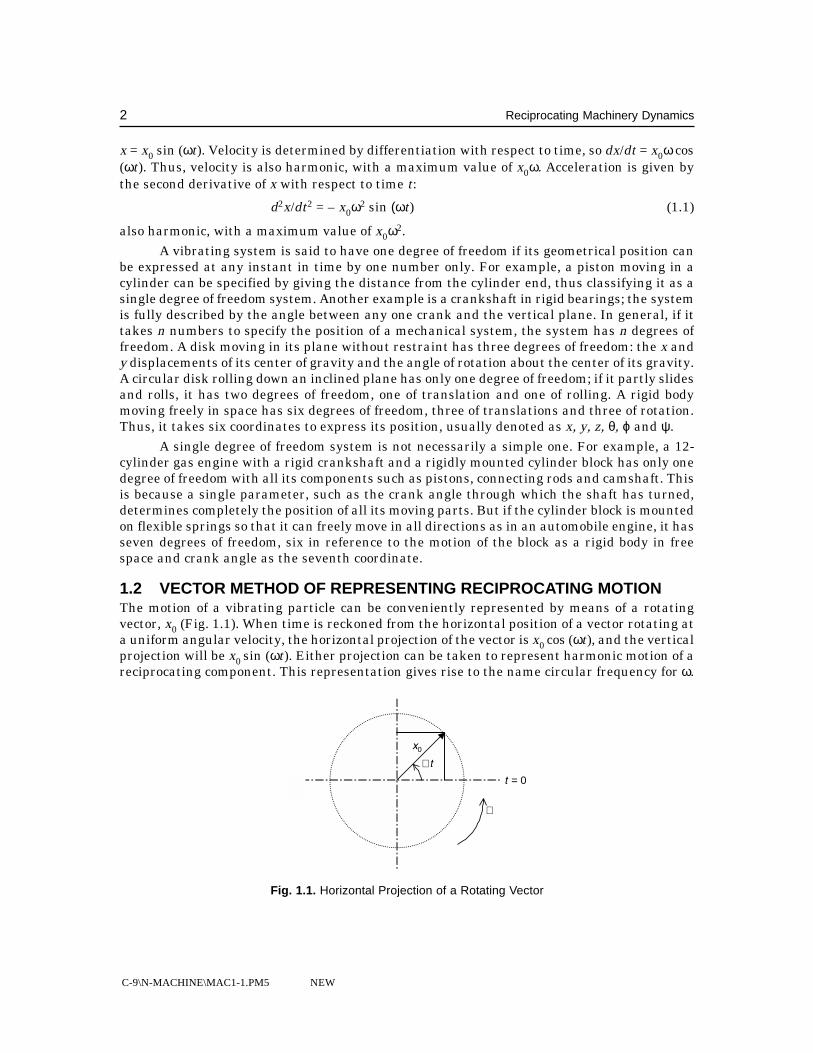
1.2 VECTOR METHOD OF REPRESENTING RECIPROCATING MOTIONThe motion of a vibrating particle can be conveniently represented by means of a rotatingvector, x0 (Fig. 1.1). When time is reckoned from the horizontal position of a vector rotating ata uniform angular velocity, the horizontal projection of the vector is x0 cos (ωt), and the verticalprojection will be x0 sin (ωt). Either projection can be taken to represent harmonic motion of areciprocating component. This representation gives rise to the name circular frequency for ω.
x0
� t
t = 0
�
Fig. 1.1. Horizontal Projection of a Rotating Vector

C-9\N-MACHINE\MAC1-1.PM5 NEW
Vibration Theory Fundamentals 3
This method of representing reciprocal motion is convenient. If a point is simultaneouslysubjected to two motions of the same frequency which differ by the phase angle φ, namely a cos(ωt) and b cos (ωt – φ), the geometric sum of the two vectors gives the total motion (Fig. 1.2).Parallelogram a, b rotates in a counter-clockwise direction with uniform angular velocity ω,and the horizontal projections of all the vectors represent displacement as a function of time.Line x – x represents a specific instant in time for which the vector diagram is drawn.Displacement of the sum is the sum of the ordinates for a and b.
y
�
a
� t a + b
0 xb
a + b
a
� t
b
Fig. 1.2. Two Vibrations Added by their Vectors
Addition of the two vectors is permissible only if vibrations are of the same frequency.Motions a sin (ωt) and a sin (2ωt) can be represented by two vectors, the first rotating at anangular speed ω, the second at twice that speed. The relative position of these two vectors ischanging continuously, thus a geometric addition of the vectors has no physical implication.
A special case of vector addition often encountered is the addition of sine and cosinewaves of different amplitudes, a sin (ωt) and b cos (ωt). The two vectors are perpendicular(Fig. 1.3), so a sin (ωt) + b cos (ωt) = [(a2 + b2)1/2] . sin (ωt + ϕ), where tan ϕ = b/a. For example,consider the sum of two motions 10 sin (25t) and 20 sin (25t + 1). At time t = 0, the first vectorpoints vertically up, with no horizontal projection. The second vector is turned 1 radian in acounterclockwise direction from the first vector. The graphical vector addition shows the sumvector to be 26.76 units long.
1.3 COMPLEX NUMBERS METHODThe vector method offers visualization of harmonic motions that is simpler than theconsideration of the sine wave by itself. For numerical calculations, however, it is not well
C-9\N-MACHINE\MAC1-1.PM5 NEW
4 Reciprocating Machinery Dynamics
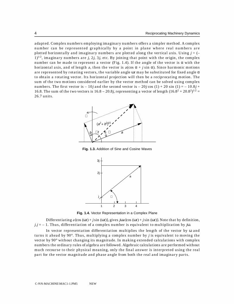
adapted. Complex numbers employing imaginary numbers offers a simpler method. A complexnumber can be represented graphically by a point in plane where real numbers areplotted horizontally and imaginary numbers are plotted along the vertical axis. Using j = (–1)1/2, imaginary numbers are j, 2j, 3j, etc. By joining that point with the origin, the complexnumber can be made to represent a vector (Fig. 1.4). If the angle of the vector is α with thehorizontal axis, and of length a, then the vector is a(cos α + j sin α). Since harmonic motionsare represented by rotating vectors, the variable angle ωt may be substituted for fixed angle αto obtain a rotating vector. Its horizontal projection will then be a reciprocating motion. Thesum of the two motions considered earlier by the vector method can be solved using complexnumbers. The first vector is – 10j and the second vector is – 20j cos (1) + 20 sin (1) = – 10.8j +16.8. The sum of the two vectors is 16.8 – 20.8j, representing a vector of length (16.82 + 20.82)1/2 =26.7 units.
�
(a2+ b2)1/2
b � t � a
Fig. 1.3. Addition of Sine and Cosine Waves
1 2 3 4
�j
2j
3j
a
Fig. 1.4. Vector Representation in a Complex Plane
Differentiating a{cos (ωt) + j sin (ωt)}, gives jωa{cos (ωt) + j sin (ωt)}. Note that by definition,j.j = – 1. Thus, differentiation of a complex number is equivalent to multiplication by jω.
In vector representation differentiation multiplies the length of the vector by ω andturns it ahead by 90°. Thus, multiplying a complex number by j is equivalent to moving thevector by 90° without changing its magnitude. In making extended calculations with complexnumbers the ordinary rules of algebra are followed. Algebraic calculations are performed withoutmuch recourse to their physical meaning, only the final answer is interpreted using the realpart for the vector magnitude and phase angle from both the real and imaginary parts.

C-9\N-MACHINE\MAC1-1.PM5 NEW
Vibration Theory Fundamentals 5
A concept of importance in many applications is that of work done by a harmonicallyvarying force on a harmonically varying motion of the same frequency. Consider a force P =Po sin (ωt + ϕ) acting upon a body for which the motion is given by x = xo sin (ωt). The work doneby the force during a small displacement dx is Pdx, which may be written as Pdt(dx/dt). Duringone cycle of vibration ωt varies from 0 to 2π/ω. After integration, the work per cycle is W = πPoxosin (ϕ).
In order to understand this expression for work a graphical approach is useful. In Fig. 1.5athe ordinates are the displacement x and the in-phase component of the force. Between A andB the force is positive, say upward, and the body is moving in the same direction, so the workdone is positive. Between B and C, on the other hand, the body moves downward toward theequilibrium point while the force is still positive, so that negative work is done. The workbetween A and B cancels that between B and C, and over a whole cycle the work done is zero.Thus, if a harmonic force acts on a body subjected to a harmonic motion of the same frequency,the component of the force in phase with the displacement does no work. Since the velocityvector is 90° ahead of the displacement, it follows that force does work only with that componentwhich is in phase with the velocity.
Dis
plac
emen
t X
XP sino
A
xo
B
P coso
C D � tA
B xo
C D � t
(a) (b)
Fig. 1.5. Work Done on Harmonic Motion, (a) In Phase and (b) 90° Out of Phase
1.4 FREE VIBRATIONS WITHOUT DAMPINGConsider a mass m suspended by a spring from a fixed location, as shown in Fig. 1.6. Stiffnessof the spring is defined by k, the force required to extend it by 1 unit. A damper is also placedbetween the mass and the fixed wall. The damper does not transmit force to the mass when atrest, but as soon as it moves it exerts a damping force of cdx/dt.
It is proportional to the velocity and directed opposite to the mass. c is the coefficient ofviscous damping. An external alternating force Po sin (ωt) is also acting on the mass. Theproblem consists in determining the motion of mass m due to this external force. The equationof motion can be obtained by applying Newton’s second law of motion, which states that forceis equal to mass multiplied by acceleration. All forces acting upward will be considered positivewhen acting downward. Spring force has the magnitude – kx, and is negative since it pullsupward. Damping force acting on the mass is also negative, – cdx/dt. The downward forcesacting on the mass are:

C-9\N-MACHINE\MAC1-1.PM5 NEW
6 Reciprocating Machinery Dynamics
mx
P sin to �
A
c k
Fig. 1.6. Single Degree of Freedom Vibrating System
– kx – c dx
dt + po sin (ωt) (1.2)
Newton’s law gives: md2x/dt2 + cdx/dt + kx = Po sin (ωt) (1.3)
This equation is known as the differential equation of motion of a single degree of freedomsystem. Before developing a solution of the general equation, simplified cases will be consideredfirst. If there is no external applied force and no damping, the equation reduces to:
md2x/dt2 + kx = 0 (1.4)The most general solution of this equation is:
x = C1 sin k
mt C
k
mt+ 2 cos
(1.5)
where C1 and C2 are arbitrary constants. Physically, the result as it stands is indefinite, sincethe constants can take any value. This is because the problem itself was not fully defined. If itis specified that the mass is pulled out of its equilibrium position to x = xo, then releasedwithout initial velocity, two conditions are specified:
At t = 0: x = xo and dx/dt = 0.The first condition gives C2 = xo. For the second condition, (1.5) must be differentiated,
then get C1 = 0. Substitution into (1.5) leads to the specific solution:
x = xo cos k
mt (1.6)
This represents an undamped vibration. Denoting the period of vibration by T, then:
T = 2π m
k(1.7)
Customarily, (k/m)1/2 is denoted by ωn, called the natural circular frequency. The naturalfrequency fn is given by:
fn =
1 1
2 2T
k
mn= =
πω
π
(1.8)
measured in cycles per second.In the derivation of the differential equation of motion the effect of gravity has been
neglected. The amplitude of vibration is measured from the position where the downward

C-9\N-MACHINE\MAC1-1.PM5 NEW
Vibration Theory Fundamentals 7
force mg is held in equilibrium by an upward force kδ, δ being the extension of the spring dueto gravity. To measure x1 from the unstressed position of the spring, then x1 = x + δ. In thedifferential equation of motion, then, x must be replaced by x1, and on the right hand side ofthe equation a force mg must be added.
If it is assumed that the motion is harmonic, the frequency can be calculated from anenergy consideration. In the center of the swing the mass has maximum kinetic energy, whileat either extreme position it has no kinetic energy. At the same time the spring is stretched (orcompressed) to the fullest at the extreme positions, and has elastic, or potential, energy storedin it. Between the middle and extreme positions the spring-mass system has both kinetic andpotential energy, the sum of which has to be constant since there is no external work done onthe system. Thus, the kinetic energy at the center position must equal elastic energy at theextreme position. For a linear spring the potential energy when stretched over a distance x is1/2kx2. The kinetic energy at any instant is 1/2mv2. If the motion is assumed to be x = xo sin(ωt), then v = xoω cos (ωt). At the extreme position the potential energy is 1/2kxo
2, and thekinetic energy at the center position where the velocity is maximum is 1/2mω2xo
2. Equatingthe two energies, 1/2kxo
2 = 1/2mω2xo2, from which ω2 = k/m, independent of the amplitude xo.
This method is of significance when dealing with problems of greater complexity, where thegeneralized energy method, known as the method of Rayleigh, leads to a result.
1.5 TORSIONAL PENDULUMFig. 1.7 shows a disk of moment of inertia I attached to a shaft of torsional stiffness k, definedas the torque necessary to produce one radian twist at the disk. The twisting motion of the diskis under the influence of an externally applied torque To sin (ωt). Since only the torsionaldisplacement ϕ is required to describe its position from the equilibrium position, this is asingle degree of freedom problem. For a rotating body, Newton’s law states that torque is equalto moment of inertia times angular acceleration, or:
T = Id2ϕ/dt2 (1.9)The three torques acting on the disk are the spring torque, damping torque and external
torque. The spring torque – kϕ, where ϕ is in radians, is negative, just as the spring force in theprevious case was – kx. The stiffness k will depend on the shaft cross-section geometry and itsmaterial shear modulus. The damping torque is – cdϕ/dt, caused by the shaft material’s internaldamping. The damping constant c is the torque on the disk caused by an angular speed ofrotation of 1 radian per second.
�
I
k
Fig. 1.7. Torsional Pendulum

C-9\N-MACHINE\MAC1-1.PM5 NEW
8 Reciprocating Machinery Dynamics
Application of Newton’s law yields the differential equation of motion:Id2ϕ/dt2 + cdϕ/dt + kϕ = To sin (ωt) (1.10)
This equation is similar to the translational case, and the solution for the undampedfree condition can be readily obtained by substituting I for m, To for P and ϕ for x in the linearcase.
Any system with inertia, elasticity and damping proportional to the velocity, where thedisplacement can be described by a single quantity, can be defined in this manner. Considertwo disks of moment of inertia I1 and I2 joined by a shaft of torsional stiffness k, (Fig. 1.8). Onthe first disk torque To sin (ωt) is acting. Both disks can assume an angular position independentof the other by twisting the shaft. However, if the quantity of interest is angle of twist in theshaft, it is possible to express the motion in terms of this quantity alone. Let ϕ1 and ϕ2 be theangular displacements of the disks, then ϕ1 – ϕ2 is the shaft twist, k(ϕ1 – ϕ2) is the springtorque, cd(ϕ1 – ϕ2)/dt is the damping torque. Applying Newton’s law to the first disk, then theequation of motion is:
To sin (ωt) = I1d2ϕ1/dt2 + cd(ϕ1 – ϕ2)/dt + k(ϕ1 – ϕ2) (1.11)
To sin � t
A
kI1 A I2
Fig. 1.8. Two Disks Mounted on an Elastic Shaft
and to the second disk, 0 = I2d2ϕ2/dt2 + cd(ϕ2 – ϕ1)/dt + k(ϕ2 – ϕ1) (1.12)
Rearranging the variables and subtracting the results from the two equations yields: (To/I1) sin (ωt) = (d2ϕ1/dt2 – d2ϕ2/dt2) + (c/I1 + c/I2)
d(ϕ1 – ϕ2)/dt + (k/I1 + k/I2)(ϕ1 – ϕ2) (1.13)Defining the twist angle (ϕ1 – ϕ2) = ψ, then multiplying the equation by the expression
I1I2/(I1 + I2) gives the equation of motion with a single variable ψ,I1I2/(I1 + I2)d2ψ/d2t + cdψ/dt + kψ = T0I2/(I1 + I2) sin (ωt) (1.14)
The solution of this equation gives information on the angle of twist, but angular rotationof individual disks cannot be obtained. A variation is shown in Fig. 1.9 where a gear and pinionsystem is attached to the shaft. Assume gears G and P to be without any inertia. Also assumingthe gear teeth to be rigid, torsional flexibility is limited to the two shafts. Gear ratio is n. Thedifferential equations of motion for this system could be derived from Newton’s law, but thesystem could be reduced to that of Fig. 1.8 by omitting the gears and replacing I2, k2 and ψ byequivalent parameters. If I2 is clamped and torque To is applied to I1, then I1 will rotate throughan angle ϕo, so k = To/ϕo. Due to the gears the torque in the shaft k2 is To/n, and the angle oftwist of k2 is To/nk2. Since I2 is fixed, this is the angle of rotation of the pinion P. Angle of the

C-9\N-MACHINE\MAC1-1.PM5 NEW
Vibration Theory Fundamentals 9
gear G is n times smaller, or To/n2k2. Adding angle To/k1 for shaft k1 gives angular rotation ofI1. Thus, the equivalent k is obtained from the expression:
1 1 1
12
2k T k n ko
o
= = +ϕ (1.5)
To sin t�
I1
A
A
k1
n, 1
P
G
k2I2
Fig. 1.9. Geared System
Now consider the inertia. Angular acceleration a in k1 and G becomes nα in k2 and P.Hence the torque in k2 is nαI2. This is also the torque at the pinion P. Gear G sees it n timeslarger, so the torque at A is n2αI2 and the equivalent of I2 in the gearless system is n2I2. Ingeneral, then, a geared system such as that of Fig. 1.9 can be reduced to an equivalent non-geared system (Fig. 1.8) in the following manner.
Divide the system into separate parts each of which has the same speed within itself.Figure 1.9 has only two parts, but there may be several. Choose one of these parts as theprimary and assign numbers n to each of the other parts so that n is the speed ratio withrespect to the primary. n > 1 for speeds higher than the primary part’s speed, while the speedratio of the primary part is unity. Next, remove all gears and multiply all spring constants kand inertias I by the factors n2. The differential equation of the reduced gearless system isthen the same as that of the original geared design.
In still another variation of Fig. 1.6, instead of the sinusoidal force acting on the mass,the upper end of the spring is made to move up and down with an amplitude ao, the motion ofA being ao sin (ωt). It can be shown that this motion of the top of the spring is equivalent to aforce on the suspended mass. If x is the downward displacement of the mass, spring extensionwill be x – ao sin (ωt), spring force is – k{x – ao sin (ωt)} and damper force is – c{dx/dt – aoωcos (ωt)}. Newton’s law then gives:
md2x/dt2 + cdx/dt + kx = kao sin (ωt) + caoω cos (ωt) (1.16)As mentioned earlier in section 1.2, the sum of a sine and cosine waves of the same
frequency is also harmonic, so:md2x/dt2 + cdx/dt + kx = [(kao)2 + (caoω)2]1/2 sin (ωt + ϕo) (1.17)
Thus, the motion of the top of the spring with amplitude ao is equivalent to a force ofamplitude {(kao)2 + (caoω)2}1/2. Terms kao and caoω in this expression are the maxima of thespring and damper forces, while the expression inside the parenthesis provides the peakmagnitude of the force when the mass is clamped.

C-9\N-MACHINE\MAC1-1.PM5 NEW
10 Reciprocating Machinery Dynamics
1.6 FREE VIBRATIONS WITH VISCOUS DAMPINGUndamped free vibrations persist indefinitely, which cannot happen; all free vibrationseliminate with time. The term viscous damping is associated with the expression cdx/dt sinceit represents the conditions of damping due to the viscosity of oil in a dashpot. Other types ofdamping exist, but their solution cannot be determined with as much ease. Consider the functionx = est, where t is the time and s an unknown constant. Upon differentiation the same functionmultiplied by a constant results. This function when substituted in the equation:
md2x/dt2 + cdx/dt + kx = 0 (1.18)permits division by est and leads to an algebraic equation instead of a differential equation.Thus, assuming est as the solution, then the above equation becomes:
(ms2 + cs + k) . est = 0 (1.19)This is a quadratic in s, with two values that will satisfy the equation:
s1, 2 = –
c
m
c
m
k
m2 2
2
± FHG
IKJ −
(1.20)
The most general solution of the problem is:x = C e C es t s t
1 21 2+ (1.21)
where C1 and C2 are arbitrary constants. The physical significance of this equation will dependon whether the expressions for s are real or complex. When (c/2m)2 > k/m, both values of s willbe real. Also, they are both negative since the square root is smaller than the first term c/2m.Thus (1.21) describes a solution consisting of the sum of two decreasing exponentials, as shownin Fig. 1.10. The case of C1 = 1 and C2 = – 2 is shown as a dashed line.
This figure shows that the motion is not oscillatory but rather a creeping back to theoriginal position. This is due to the fact that when (c/2m)2 > k/m the damping c is large. Forsmaller values of c pertaining to more practical cases, (1.20) gives complex values for s. Thedamping c at which this transition occurs is called the critical damping cc:
cc = 2m k
mm k= 2 = 2 mωn (1.22)
If the damping is less than critical damping, the solution consists of two factors, the firsta decreasing exponential and the second a sine wave. The combined result is an exponentiallydecreasing sine wave, lying in the space between the exponential curve on both sides of thephase angle axis (Fig. 1.11). The smaller the damping constant c, the flatter will be theexponential curve and the more cycles it will take for the vibrations to be eliminated.
1
0
–1
es t1
es t2
12 3 t
Fig. 1.10. Motion of Single Degree of Freedom System with c/cc > 1

C-9\N-MACHINE\MAC1-1.PM5 NEW
Vibration Theory Fundamentals 11
A1
0
–1
� 2� 3� 4� 5�
C
B
Fig. 1.11. Free Vibration of a System with c/cc < 1
The rate of this dying down of the vibrations is of interest, and can be calculated byconsidering two consecutive maxima of the curve, A – B, B – C, and so on. During the timeinterval between any two such maxima, the amplitude of vibration diminishes from:
ec
mt−
2 to e
c
mt
q− +
RSTUVW2
2π
where q = k
m
c
m−
2
24(1.23)
The latter of these two expressions is equal to the first one multiplied by the constantfactor:
e
c
m q− π.
(1.24)which factor is smaller than unity. This factor is the same for any two consecutive maxima,and is independent of the amplitude or of time. Thus, the amplitudes decrease in a geometricseries.
The frequency of vibration diminishes with increasing damping. If written in adimensionless form with the help of (1.23), it becomes:
q c
cn cω= −
RSTUVW
12
(1.25)
This equation is plotted in Fig. 1.12, where the ordinate q/ωn is the ratio of the dampedto the undamped natural frequency, and the abscissa is the ratio of the actual to the criticaldamping. The figure is a circle; for critical damping the natural frequency is zero. Due to thehorizontal tangent of the circle at c = 0, the natural frequency is nearly constant and equal to
( / )k m for all typically encountered values of damping (c/cc < 0.2).
1.0
0.5
c/cc
0 1.0
q/�
n
Fig. 1.12. Natural Frequency as a Function of Damping

C-9\N-MACHINE\MAC1-1.PM5 NEW
12 Reciprocating Machinery Dynamics
1.7 FORCED VIBRATIONS WITHOUT DAMPINGAnother particular case of (1.3) is the one where the damping term is made zero:
md2x/dt2 + kx = Po sin (ωt) (1.26)Substituting a harmonic solution of the type x = x0 sin (ωt) into this equation yields:
– mω2xo sin (ωt) + kxo sin (ωt) = Po sin (ωt) (1.27)producing the result:
x = P ko
n
/
( / )1 2− ω ω sin (ωt) (1.28)
The expression Po/k has the same physical significance of static deflection of the springunder a constant load Po. Thus, if Po/k = xst, the solution becomes:
x
x nst
=−
1
1 2( / )ω ω sin (ωt) (1.29)
Including the homogeneous solution containing the two integration constants, the totalsolution of the problem becomes:
x = C1 sin (ωnt) + C2 cos (ωnt) + x
n
st
1 2− ( / )ω ω sin (ωt) (1.30)
The first two terms represent the undamped free vibrations, the third term is theundamped forced vibration. Examining the implications of this result, x/xst is a sine wave withan amplitude of 1/{1 – (ω/ωn)2}. For values of ω/ωn > 1 the amplitudes are negative, and of ω/ωn< 1 the amplitudes are positive. When the amplitudes are negative, it only means that theamplitudes are positive but with a phase angle lag of 180°. It also means that for ω/ωn < 1 forceand motion are in phase, and they are out of phase for ω/ωn > 1. For ω/ωn < 1 the mass is belowthe equilibrium position when the force pushes downward; the mass is above the equilibriumposition when the force pushes downward for ω/ωn > 1. At ω/ωn = 1 the forced frequency coincideswith the natural frequency, so the force is pushing the mass at the right time in the rightdirection. The amplitude then increases indefinitely. In the case of a pendulum, it is pushedslightly in the direction of motion every time it reaches the end of a swing; a small force isrequired to produce a large amplitude. This phenomenon is known as ‘resonance’, and thenatural frequency is called the ‘resonant frequency’.
Fig. 1.13. Unbalanced Rotating Machine on a Beam
An important application of this theory is when the amplitude of the impressed forcevaries with ω2. Fig. 1.13 shows a beam on two supports carrying a rotating machine with anunbalanced centrifugal force of m1ω2r, where m1 is the unbalance mass and r is its distancefrom the center line of the shaft. This force can be resolved into a vertical component m1ω2r sin(ωt) and a horizontal component m1ω2r cos (ωt). If it is assumed that the beam is rigid for

C-9\N-MACHINE\MAC1-1.PM5 NEW
Vibration Theory Fundamentals 13
displacements in the horizontal direction, and flexible for displacements in the vertical direction,then it becomes a single degree of freedom system. Here the motor mass m and beam stiffnessk = 48EI/l3 are acted upon by the frequency dependent vertical disturbing force of amplitudem1ω2r. Considering the motion of the motor and beam system, it is equivalent to motor massinertia force of mω2ao acting on the beam. The solution for this problem can be found directlyfrom (1.28) by substituting mω2ao for Po. Then:
8
7
6
5
4
3
2
1
00 1 2 3
B
A
C
y/a o
o
� �/ n
Fig. 1.14. Resonance Diagram for Rotating Machine on a Beam Example
yo = m a kao
no
n
n
ωω ω
ω ωω ω
2
2
2
21 1
/
( / )
( / )
( / )−=
−
or y
ao
o
n
n
=−( / )
( / )
ω ωω ω
2
21(1.31)
If yo/ao is plotted as a function of ω/ωn, the result is shown in Fig. 1.14. At C there isresonance, and so spring extension is infinitely large in the absence of damping. Since thisresult is not in agreement with observations, it is necessary to consider damping. It shows therelative motion of a system in which the end of the spring is subjected to an alternating motionof constant amplitude ao. The plot also shows the absolute motion of a system in which themass experiences a force of variable amplitude mω2ao. The ordinates of the three points A, Band C representing (1.31) can be physically explained as follows. At A the frequency ω is nearlyzero, so the top of the spring moves at a slow rate, the mass follows this motion and the springdoes not stretch, and so yo = 0. At B the motion of the top of the spring is very rapid, so the masscannot follow and stands still in space.
1.8 FORCED VIBRATIONS WITH VISCOUS DAMPINGThe complete equation of motion is:
md2x/dt2 + cdx/dt + kx = Po sin (ωt) (1.32)The full solution consists of the complete solution of the equation with the right hand
side set to zero and a particular solution of the whole equation (1.32), or:

C-9\N-MACHINE\MAC1-1.PM5 NEW
14 Reciprocating Machinery Dynamics
x = ec
mt−
2 {C1 sin (qt) + C2 cos (qt)} particular solution (1.33)Thus, only the particular solution needs to be determined. Assuming a solution of the
type x = xo sin (ωt – ϕ), the particular solution can be determined by finding xo and ϕ. Newton’slaw requires that the sum of all the forces be zero at all times, implying that the sum of thevertical and horizontal components must also be zero. From these conditions the unknowns xoand ϕ are solved:
xo = P k
c
c
o
n c n
/
1 22
2
2 2
−RST|
UVW|+RST
UVWωω
ωω
(1.34)
tan (ϕ) = 2
1 2 2
c
cc n
n
ωω
ω ω− ( / )(1.35)
The expressions for the amplitude and the phase angles are in terms of ratios of frequencyand damping, where cc is the critical damping. P0/k may be interpreted as the static deflectionof the spring due to P0. These relations are plotted in Fig. 1.15. The amplitude diagram containsa family of curves, one for each value of damping. All curves lie below the one for zero damping,since the amplitude of forced vibration is reduced by damping. The maxima of the differentcurves do not occur any more at ω/ωn = 1 but at a smaller frequency. In fact, three differentfrequencies need to be distinguished, all of which coincide for c = 0:
• ωn = ( / )k m = undamped natural frequency
• q = k
m
c
m− RST
UVW2
2
= damped natural frequency
• The frequency of maximum forced amplitude, or the resonant frequency.The phase angle diagram is also of interest. For no damping it was seen that the force
and displacement are in phase below resonance and 180° out of phase above resonance. So thephase angle shows a discontinuous jump at the resonance point. For damping values differentfrom zero the other curves in the phase angle diagram are plotted. In general, damping tendsto smooth out the sharpness of the undamped diagrams for both amplitude and phase.
Energy relations involved in this process also give a deeper understanding. For veryslow motions ϕ = 0, and little work is done over a whole cycle, or no mechanical energy isconverted into heat. Starting from the equilibrium position, the external force moves througha certain distance before reaching the extreme position, when it does work. But that work isused to store potential or elastic energy into the spring. During the next quarter cycle themotion goes against the external force and the spring gives up its stored energy. At slow speeds,then, the work of the external force is transferred into elastic energy and nothing is convertedinto heat. At resonant frequency ϕ = 90°, and work dissipated per cycle is πPoxo. The externalforce is equal and opposite to the damping force in that case, so the work is dissipated by thedamper. The spring force and the inertia force are equal and opposite, and also in phase withdisplacement. Each of these forces individually perform work during a quarter cycle, but storethe energy, returning it during the next quarter cycle. The work is stored periodically as elasticenergy in the spring and as kinetic energy in the mass.

C-9\N-MACHINE\MAC1-1.PM5 NEW
Vibration Theory Fundamentals 15
5
4
3
2
1
00 1 2 3
c/c = 1cc/c = 1c
c/c = 0cc/c = 0c
c/c = 0.125cc/c = 0.125c
c/c = 0.20cc/c = 0.20c
c/c = 0.50cc/c = 0.50c
X/S o
stat
� �/ n
(a)180
150
120
90
60
30
00 1 2 3� �/ n
Pha
seA
ngle
,deg
rees
�
c/c = 0cc/c = 0c
c/c = 0.125cc/c = 0.125c c/c = 0.5cc/c = 0.5c
c/c = 0.20cc/c = 0.20c
c/c = 1.0cc/c = 1.0c
(b)Fig. 1.15. (a) Amplitudes of Forced Vibrations, (b) Phase Angle Between Force
and Displacement as a Function of Frequency for Various Damping Values
Returning to the assertion pertaining to the particular solution, the general solutionconsists of the damped free vibration superposed on the forced vibration. After a short timethe damped free vibration disappears and the forced vibration alone persists. For this reasonthe forced vibration may also be referred to as sustained vibration and the free vibration becomestransient vibration. The values of the constants C1 and C2 depend on the conditions at thestart and can be calculated from these conditions using the analytical process described earlier.

C-9\N-MACHINE\MAC1-1.PM5 NEW
16 Reciprocating Machinery Dynamics
It is possible to describe the whole process by physical reasoning. For example, consider amass suspended by a spring and acted upon by an external harmonic force of frequency eighttimes as slow as the natural frequency of the system. The mass is clamped while the externalforce is acting. Suddenly the clamp is withdrawn. Assume the damping in the system is suchthat the free vibration decreases by 10 percent for each cycle. Assume also that the clamp isreleased when the forced vibration has its maximum amplitude. From the initial conditions itfollows that at the instant of the release the mass has no deflection and no velocity. Theprescribed forced vibration starts with x = xo and dx/dt = 0. These two conditions can only besatisfied by starting a free vibration with x = – xo and dx/dt = 0. Then the combined motion willstart at zero with zero velocity. Fig. 1.16 (a) shows the free vibration, 1.16 (b) shows the forcedvibration and 1.16 (c) the combined motion.
(a) Free Motion
(b) Forced Motion
(c) Total Motion
Fig. 1.16. Starting Transient Motion of a Forced Vibration
Note that the transient vibration disappears quickly and that the maximum amplitudeat the start is nearly twice as great as the sustained final amplitude. If the difference betweenfree and forced frequencies is small and damping is also small, the free and the forced vibration

C-9\N-MACHINE\MAC1-1.PM5 NEW
Vibration Theory Fundamentals 17
vectors would retain nearly the same relative motion during one revolution, the included anglebetween them changing only slightly. The vectors can then be added geometrically, and duringone revolution of the two vectors the motion will practically be a sine wave of frequency ω1 ≈ ω2and amplitude the arithmetic sum of the two amplitudes. After a large number of cycles, therelative position of the vectors varies, and the magnitude of the sum vectors also changes. Theresulting motion can then be described as an approximate sine wave with frequency ω1 and anamplitude varying slowly between the sum and the difference of the amplitudes of the free andforced vibrations. This phenomenon is known as beats. Note that the free vibrations will beeliminated after a while due to energy dissipation from the damping. In order to have sustainedbeats it is necessary to have two sustained, or forced, vibrations.
1.9 VIBRATION DUE TO ROTATING ECCENTRIC WEIGHTA classic example of forced vibrations with viscous damping is that of a rotating machine ofmass m with a rotating eccentric mass mu mounted in a shaft and bearings, Fig. 1.17. Therotating eccentric mass mu follows a circular path of radius e with respect to the bearings.Considering only the motion in the vertical direction, the displacement of mass mu relative tom is x2 – x1 = e sin (ωt), where x2 and x1 are the absolute displacements of mu and m and ω theangular speed of the machine rotor.
The differential equation of motion of the system is: mud2x/dt2 + m1d2x/dt2 + cdx1/dt + kx1 = 0 (1.36)
Differentiating (x2 – x1) with respect to time and substituting in (1.36),(mu + m1)d2x/dt2 + cdx1/dt + kx1 = mueω2 sint (ωt) (1.37)
This equation is of the same form as (1.32): by substituting (m + mu) for m and mueω2 forPo the resulting displacement, velocity and acceleration of the rotating machine mass m can bereadily obtained. Note that the magnitude of eccentric mass mu will be insignificant comparedto the machine mass m.
x1
k
x2
mu
m
c
e
Fig. 1.17. Forced Vibrations from Rotating Eccentric Weight
When the machine is mounted on an elastic foundation, the motion of the foundationcomes into play. As discussed earlier in section 1.7, displacement forced on an otherwise unforcedsystem is equivalent to a system where a force is applied on that system. Therefore, a rotatingmachine with an eccentric mass in the rotor mounted on an elastic foundation behaves as iftwo distinct forcing functions are applied on it, one due to the eccentric mass whose frequency

C-9\N-MACHINE\MAC1-1.PM5 NEW
18 Reciprocating Machinery Dynamics
coincides with the angular speed of the rotor, and the other due to motion from the foundation.The frequency of the foundation motion will depend on the elastic stiffness of the foundationand the mass of the rotating machine. Damping characteristics of the foundation will controlthe amplitude of motion of the machinery from both sources of excitation, since the foundationwill be in the direction of the load path traveling from the rotor to the foundation. Relativemotion between the rotor and machine housing will be dependent on the material damping ofthe shaft and the bearings.
As an example of the above discussion, consider a centrifugal compressor weighing3,000 lb. mounted on a simply supported elastic beam of negligible weight, of the type shownin Fig. 1.13. The elastic beam sags 9 in. under the weight of the compressor, and has a dampingcoefficient of 28 lb. for a velocity of 1 in. per second. The elastic beam is moved up and down atresonant speed with an amplitude of 1 in. Assume the center of the compressor to coincidewith the center of the beam along the beam’s length. The natural frequency of vibration is (g/δst)1/2 = (386/9)1/2 = 6.6 rad./second. At resonance the disturbing force is {(kao)2 + (caoω)2}1/2.Here stiffness of the beam k = 3000/9 = 333 lb./in; ao = 1 in.; damping c = 28 lb.-second/in; andnatural frequency ω = ωn = 6.6 radians/second. The disturbing force is then equal to 380 lbs.The amplitude of motion of the compressor then is disturbing force divided by the product of cand ω, and is found to be 2.07 in.
1.10 ROTATING AND RECIPROCATING UNBALANCEAn important group of vibration phenomena of practical importance in reciprocating machinesis torsional oscillations in the crankshaft and in the shafting of driven machinery. The effect iscaused by a combination of periodic accelerations of moving parts (piston, connecting rod,crank) and periodic variations in cylinder steam or gas pressure.
In a single cylinder vertical reciprocating machine the piston executes an alternatingmotion, and in the process experiences alternating vertical accelerations. When the pistonaccelerates downward there must be a downward force acting on it, and this force must have areaction pushing upward against the stationary parts of the engine. Thus, the alternatingacceleration of the piston is coupled with an alternating force on the cylinder frame, makingitself felt as a vibration in the engine and its supports. In the lateral direction perpendicular toboth the crankshaft and the piston rod, moving parts are also being accelerated, namely thecrank pin and part of the connecting rod. The forces that cause these accelerations must haveequal and opposite reactions on the frame of the machine. This last effect is the horizontalunbalance. In the crankshaft main axis no inertia forces appear, since all moving parts remainin planes perpendicular to the crankshaft.
These various inertia forces can cause moments. Consider a two cylinder vertical machinewith the cranks set 180° apart. While one piston is accelerated downward the other piston isaccelerated upward, and the two inertia forces form a couple tending to rock the machineabout a lateral axis. Similarly, the horizontal or lateral inertia forces of the two cranks areequal and opposite, forming a couple tending to rock the machine about a vertical axis.
A rocking about the crankshaft axis can occur even in a single cylinder machine. If thepiston is accelerated downward by a pull in the connecting rod, this pull exercises a torqueabout the crankshaft axis. Since the piston acceleration is alternating, this inertia torque isalso alternating.
If the whole machine mounted on weak springs is considered as the mechanical system,the external torque is zero, and so any increase in clockwise angular momentum of the movingparts must be neutralized by an increase in counterclockwise angular momentum of the

C-9\N-MACHINE\MAC1-1.PM5 NEW
Vibration Theory Fundamentals 19
stationery parts of the machine. Taking merely the moving parts of the machine as themechanical system, an increase in the clockwise angular momentum of the moving parts mustbe caused by a clockwise torque on these parts, which has a counterclockwise reaction torqueon the frame. If the machine frame is mounted solidly on its foundation, this counter torque istransmitted to the foundation and may cause trouble. But if the machine is mounted on softsprings, reaction to the foundation cannot penetrate through these springs and the countertorque is absorbed as an inertia torque of the frame and cylinder block, and the machine blockmust vibrate.
In Fig. 1.18 inertia forces are excluded by assuming the machine to be turning at a slowconstant speed ω, or the moving parts have negligible mass. The pressure force on the piston isP, and is varying with time, or with crank angle ωt. Besides acting on the piston, the gaspressure also presses upward against the cylinder head. Force P is transmitted through thepiston rod (force 1) to the cross head. Neglecting friction, it is held there in equilibrium byforces 2 and 3. Of the forces acting on the cross head, 3 is a compression in the connecting rod,and 2 is a reaction pressure on the frame to the right, of magnitude P tan (φ). Force 3of magnitude P/cos (φ) is transmitted through the connecting rod to the crank pin (force 4).Shifting this force parallel to itself to O and adding a torque yP/cos (φ), the driving torque ofthe gas pressure is obtained. Force 5 is taken up by the main bearings at O and can be resolvedinto a vertical component 6 and a horizontal component 7. Triangles 1, 2, 3 and 5, 6, 7 are similar,so the magnitude of 6 is P and that of 7 is P tan (φ).
Pressure P
�
l
A B
D
� tr
O
y
P
1
2P tan �
3 x
O5
64
x
y7
Fig. 1.18. Gas Pressure Load on a Single Cylinder Machine
The forces transmitted to the stationery parts of the machine are P upward on thecylinder head, P tan (φ) to the right on the cross head guide, P downward on the main bearingsat O and P tan (φ) to the left on the main bearings at O. The total resultant force on the frame

C-9\N-MACHINE\MAC1-1.PM5 NEW
20 Reciprocating Machinery Dynamics
is zero, but there is a resultant torque Px tan (φ). From Newton’s law of action and reaction,this torque must be equal and opposite to the driving torque on the crankshaft, yP/cos (φ). Thisis easily verified, because y = x sin (φ). Thus, the gas pressure forces do not cause any resultantforces on the machine, producing only a torque about the main crankshaft axis.
In summary, no forces occur along the longitudinal crankshaft axis of an machine, whilein the lateral and vertical directions only inertia forces appear. About the vertical and lateralaxes only inertia torques are found, and in the longitudinal direction both an inertia torqueand a cylinder gas pressure torque occur.
If the machine is assumed to be built of elastically non-deformable members, the problemis one of static balance only. The frame and other stationary parts generally fulfill this condition,but the crankshaft can be twisted significantly, making torsional vibrations possible. The subjectmay be divided into three categories:
(a) Inertia Balance: This refers to the balancing of the machine against vertical andlateral forces, and against moments about vertical and lateral axes.
(b) Torque Reaction: Under this heading the effects of torque due to inertia and gaspressure acting on the stationary parts about the longitudinal axis are analyzed.
(c) Torsional Vibrations of Crankshaft: Consequences of the longitudinal torque on themoving parts of the reciprocating machine are dealt with.
Effect c is of particular importance since many crankshafts have encountered failuresdue to the longitudinal torque.
1.11 VIBRATION ISOLATIONAn unbalanced machine has to be installed in a structure where the vibrations are undesirable.Prime examples of this situation are gas turbine engines attached to an airplane wing andautomotive engines. The problem is one of mounting the machine in such a manner that novibrations will appear in the structure to which it is attached.
Probably the most popular solution consists of mounting the machine on springs. InFig. 1.19 the machine is represented as a mass m with a force Po sin (ωt) acting on it. In figurea it is solidly attached to the structure, and in figure b it is mounted on springs with a combinedstiffness k. For simplicity the machine is assumed to be rigid.
P sin ( t)o �
m
P sin ( t)o �
m
k
(a) (b)
Fig. 1.19. Flexible Spring Mount for Preventing Vibration Transmission to Foundation
The problem is one of finding the magnitude of the force transmitted to the floor by themachine. Since only the springs are in contact with the foundation, the only force transmitted

C-9\N-MACHINE\MAC1-1.PM5 NEW
Vibration Theory Fundamentals 21
is the spring force, and that has the amplitude kx, damping being neglected here. If xo is thedisplacement of the mass and xst = Po/k is the static displacement, then:
x
x
x
P k
kx
Po o
o
o
ost
spr ing force
impressed for ce= = =
/
= t ransmit ted force
impressed force = Transmissibility (1.38)
The ideal is to have this ratio zero, but practical considerations aim to make it small. Ifthe spring constant k = ∞, as in figure a, the natural or resonant frequency is infinite. Theoperating frequency is then small compared to the natural frequency, ω/ωn is nearly zero andthe transmitted force equals the impressed force. Physically this is obvious, since the rigidfloor does not permit mass m to move, and all the force Po is transmitted to the foundation. Itis necessary to design the support springs so as to make the natural frequency of the wholemachine low compared with the disturbance frequency. Thus, the springs should be soft.
Other interesting observations can be made from (1.29). If ω is smaller than ωn 2 =(2 /k m ) , the springs make matters worse, since the transmissibility is greater than unity. If
the natural frequency is one-fifth of the disturbing frequency, the transmissibility is 1/24, agood ratio.
So far the support has been considered without damping, which is the case in steelsprings. If cork or rubber padding is used for the purpose, then damping is not negligible andmust be accounted for. The system is then represented by Fig. 1.20. Now the displacementcurve is not directly proportional to the amplitude of the transmissibility curve. The force ismade up of spring force kxo as well as the damping force cωx0. As shown earlier the two forcesare out of phase by 90°. Consequently, their vector sum is the total transmitted force. Theamplitude x0 is given by the following expression:
Transmitted force = Po 1
1 2
2
2
2
2 2
+ RSTUVW
−RST|
UVW|+RST
UVW
c
k
c
cn c n
ω
ωω
ωω
(1.39)
Transmissibility is defined as the ratio of transmitted force to impressed force. Thus,damping is advantageous only in the region ω/ωn < 1.41, where spring mounting makes mattersworse. For all values of ω/ωn where spring mounting helps, the presence of damping makes thetransmissibility worse. However, this statement is not as important as it may appear at firstsight. For one thing the effect of damping is not great, and can be easily offset by making thesprings weaker. Secondly, operation at resonance point ω/ωn = 1 is never the intention, althoughit may sometimes unfortunately occur, and then the presence of damping is highly desirable.Thus, in spite of the dictum, some damping in the springs is generally advantageous.

C-9\N-MACHINE\MAC1-1.PM5 NEW
22 Reciprocating Machinery Dynamics
P sin ( t)o �
m
k/2k/2
xc
Fig. 1.20. A Spring Support with Damping
Practical cases of isolation by means of springs occur in many machines. Their mainapplication lies in apparatus that is inherently unbalanced, or as in the case of most reciprocatingmachines, inherently has a non-uniform torque. The case of internal combustion engines usedin automobiles is discussed in detail in the next section.
1.12 APPLICATION TO AUTOMOBILE ENGINESBefore discussing the vibration transmission of the automobile engine, a brief introduction tocylinder-pressure torque and its variation with crank angle, or time, will be useful. This topicwill be discussed at length in later chapters. Internal combustion engines operate in a cyclethat have four distinct regimes. During the intake phase fresh air is sucked into the cylinderthrough the inlet valves. In an engine operating on four-cycles this phase occurs when thepiston is near 0° crank angle, close to the cylinder head, and lasts till the crank angle reachesapproximately 180°. At this instant the piston reaches the lower dead center. At the end of thestroke the inlet valves close and the compression cycle begins, lasting from about 180° crankangle to 360° crank angle, when the piston is once again at the top dead center. The firingphase of the cycle then begins, with the spark ignition occurring just after the piston hasreached top dead center. As the flame spreads throughout the cylinder and the crank turning,the gases expand and perform work on the piston by pushing it to the other end of the cylinder.At approximately 180° crank angle the exhaust valves open and the spent gases then exit thecylinder, at the end of which the piston reaches once again to the top dead center to commencethe next cycle. In a four cycle single cylinder engine, at the four dead center positions duringthe two revolutions of a firing cycle, the torque is zero. Thus, the average torque delivered bythe cylinder is only a small fraction of the maximum torque that occurs during the firingperiod. The fact that the torque is so irregular constitutes one of the primary disadvantages ofthe reciprocating engine as compared with a turbine where the torque curve as a function oftime is a straight horizontal line.
According to Newton’s law, every action is accompanied by an opposite reaction, anddue to the torque generated by the cylinder gas pressure on the crankshaft the engine blockwould experience a counter rotating torque. With the engine mounted rigidly on the frame,these torque variations have reactions on the automobile’s frame, and total such that the naturalfrequency of vibration is appreciably lower than n/2 times the running speed. Uncoupling ofdynamic motion is accomplished by mounting the engine block on two journals, fore and aft,supported in bearings attached to the chassis, enabling the block to rotate about an axis nearlyparallel to the torque axis and passing through the center of gravity, shown as axis AA inFig. 1.21. With any other mount arrangement than the one described, the engine block would

C-9\N-MACHINE\MAC1-1.PM5 NEW
Vibration Theory Fundamentals 23
be free to rotate about axis AA. To prevent this, a cantilever leaf spring B between the engineblock and the chassis is used, the stiffness of which is selected such as to make the naturalfrequency sufficiently low.
Besides cylinder pressure torque the engine also experiences horizontal and verticalinertia forces, which have to be reacted at mount points A and B. For this reason both bearingsA as well as the chassis end of the leaf spring B are embedded in rubber. In the actualconstruction axis AA is not exactly parallel to the torque axis. This is the right procedure,because generally the torque axis is not the principal axis of inertia, and consequently doesnot coincide with the corresponding axis of rotation. Any rigid body has three principal axes ofinertia. For instance, take an elongated solid rectangular steel bar, Fig. 1.22, and attach to it aweightless shaft passing through its center of gravity, but not coinciding with one of its principalaxes of symmetry. Application of a sudden torque to the assembly will cause it toaccelerate. Multiplying the acceleration with the masses of elements in the bar gives inertiaforces, and multiplying the forces by their distance from the axis of rotation form a torque,which is equal and opposite to the impressed torque. Also these forces when multiplied bytheir distance from the axis perpendicular to the shaft have a torque about that axis. This willhave reaction at the two bearings; the right hand bearing experiences a force out of the planeof the diagram, the left hand bearing force being pushed into the plane. In the absence of thebearings, under the influence of the torque the bar would not rotate about the torque axis,since forces are required at the bearings to make it do so. In general, then, a body under theinfluence of a torque will rotate about an axis not coinciding with the torque axis if that is nota principal axis.
The axis about which the automobile engine has to be suspended, therefore, should notbe about the torque axis itself but the axis of rotation to which the torque axis belongs. Onlywhen the torque axis is a principal axis do the two coincide. Several other design schemes ofspring-supported automobiles are available, most of which are similar to that of Fig. 1.21.Some have one rubber support at the rear of the engine and two other rubber supports closetogether at the same height in the front. These two supports are virtually a combination of thesingle bearing A and the restoring spring B of Fig. 1.21.
a
B
AA A
l
Fig. 1.21. Schematic Arrangement of Automobile Engine Mount

C-9\N-MACHINE\MAC1-1.PM5 NEW
24 Reciprocating Machinery Dynamics
Torque
Fig. 1.22. Rotation of Bar about an Axis Different from its Principal Axis of Inertia
To illustrate the above discussion, consider a four cylinder automobile engine weighing400 lb. supported in the same manner as in Fig. 1.21. The radius of gyration of the engineabout axis AA is 6 in., distance a is 18 in. and length l of the cantilever is 4 in. The diameter ofthe rear wheels is 30 in., and in high gear the engine makes three revolutions per revolution ofthe rear wheels. The requirement is that the engine be in resonance at a speed correspondingto 3.5 miles per hour, or 61.6 in. per second, in high gear. Wheel circumference is 30π = 94.25in. At the critical speed the wheel makes 61.6/94.25 = 0.65 revolutions per second, so theengine runs at 3 × .65 = 1.95 r.p.s. Now, the engine torque curve goes through a full cycle forevery firing, and since there are two firings per revolution in a four cylinder, four cycle engine,there will be 3.9 firings per second. For resonance, then, the frequency of the engine will be fn= 3.9 cycles per second, or, ωn
2 = 4π2(3.9)2 = 600 rad2/sec2 = k/I. Here k is defined as the torquerequired in the cantilever per radian twist. The deflection at the end of the cantilever for atwist of ϕ radians is 18ϕ in. If k1 be the linear stiffness of the cantilever in lbs/in., the springforce is 18k1ϕ lbs acting on a moment arm of 18 in., so the torque is 18 × 18k1ϕ in.-lbs. Thus, k= 324k1. Also, since the moment of inertia I = 400 × (6)2/386 = 37.3 in.-lb.-sec2, then ωn
2 = 600= 324 × k1/37.3 and k1 = 37.3 × 600/324 = 69 lbs per in.
Note that in this example if one cylinder was firing inadequately another periodicity isintroduced in the torque curve for each two revolutions of the engine. Since the disturbance isfour times as slow as the one discussed, it will be in resonance with the natural frequency ofthe engine at a speed of 4 × 3.5 = 14 miles per hour. Still another possibility is when thecylinders are not firing at the proper instant in time, when the overall dynamic characteristicswill change.
1.13 EXAMPLE PROBLEMSExample Problem 1.1:Example Problem 1.1:Example Problem 1.1:Example Problem 1.1:Example Problem 1.1: A force 5 sin (2π 60t) acts on a displacement of (1/10) sin (2π 60t – π/4). What is the work done during the first second? (Units: inch, pound, seconds).Solution:Solution:Solution:Solution:Solution: The force is π/4 radians (45°) out of phase with the displacement; so it can be resolvedinto two components, each of magnitude 5/ 2 lb. in phase and 90° out of phase withdisplacement. The component in phase with the displacement does no work. Work done by the90° out of phase component per cycle is: πPoxo = π . (5/ 2 ) . (1/10) = 1.11 in-lbs. In the firstsecond there are 60 cycles, so work performed is 60 × 1.11 = 66.6 in-lbs.66.6 in-lbs.66.6 in-lbs.66.6 in-lbs.66.6 in-lbs.Example Problem 1.2:Example Problem 1.2:Example Problem 1.2:Example Problem 1.2:Example Problem 1.2: In the above example what is the work during the first 1/1000 second?Solution:Solution:Solution:Solution:Solution: In the first 1/1000 second there will be 60 × 1/1000 = 0.06 cycle, or 0.06 × 360° =21.6°. For part of the cycle, work is determined by integration.
W = P dx Po=z z sin (ωt) . xoω . cos (ωt – ϕ) dt

C-9\N-MACHINE\MAC1-1.PM5 NEW
Vibration Theory Fundamentals 25
= 5(1/10)
sin ( ).
ωt0
21 6°z
. cos (ωt – 45°) d(ωt)
= {(1/4) cos (45°) . sin2 (ωt) + (1/2) sin (45°)[ωt/2 – (1/4) sin (2ωt)]}021.6°
= (1/4) × (0.707) × (0.368)2 + [21.6 × 0.707/(4 × 57.3)] – 0.707 × 0.685/8= + 0.030 in-lb.+ 0.030 in-lb.+ 0.030 in-lb.+ 0.030 in-lb.+ 0.030 in-lb.
Example Problem 1.3Example Problem 1.3Example Problem 1.3Example Problem 1.3Example Problem 1.3: In the system shown in Fig. 1.23 the mass weighs 2 lb., spring stiffnessis 25 lb./in.; l = 8 in. and a = b = 3 in. Also a damper is attached at the mid point of the beam,where the spring is fastened. The damper constant is 0.005 lb./in/sec. What is the dampercritical damping?Solution:Solution:Solution:Solution:Solution: The undamped natural frequency is ωn =
( / )k m
. The equivalent spring constant isk . a2/l2, or 25 × (9/64) = 3.5 lb./in. Then:
ωn = ( / ) ( / )k m = ×3.5 386 2 = 26.0 radians/sec.The critical damping constant is:
cc = 2mωn = 2 × (2/386) × 26.0 = 0.27 lbs/in/sec.0.27 lbs/in/sec.0.27 lbs/in/sec.0.27 lbs/in/sec.0.27 lbs/in/sec.
a b
l
m
k
Fig. 1.23
Example Problem 1.4:Example Problem 1.4:Example Problem 1.4:Example Problem 1.4:Example Problem 1.4: Find the rate of decay of free vibration in the example problem # 1.3.Solution:Solution:Solution:Solution:Solution: The rate of decay is:
∆x/x = δ = 2π × (c/cc) = 2π × (0.005/0.27) = 0.116.0.116.0.116.0.116.0.116.Example Problem 1.5:Example Problem 1.5:Example Problem 1.5:Example Problem 1.5:Example Problem 1.5: A variable length cantilever beam consists of a strip of spring steel0.20 in. wide and 0.020 in. thick. It carries a weight of 1/4 oz. at its free end. What should be thefree length of the strip if it is required to have frequencies from 6 cycles/sec. to 60 cycles/sec?Solution:Solution:Solution:Solution:Solution: The spring constant of a cantilever beam is 3EI/l3. The moment of inertia of thecross section is:
I = (1/12)bh3 = .2 × (.02)3/12 = 1.33 × 10⁻⁷ in4.Bending constant EI = 30 × 106 × 1.33 × 10–7 = 4.0 lbs-in2, so spring constant k = 12/l3 lbs/
in. At the end, mass m = 1/(4 × 16 × 386) = 4.05 × 10⁻⁵ lbs-in–1-sec2.Mass per inch length of strip µ = 0.2 × 0.02 × 0.28/386 = .29 × 10–5 lbs-in–1-sec2. So total
mass = (4.05 + 0.29l) × 10-5 lbs-in–1-sec2.

C-9\N-MACHINE\MAC1-1.PM5 NEW
26 Reciprocating Machinery Dynamics
Maximum length frequency is 6 cycles/sec, or, ω2 = (2π × 6)2 = 1421 (radians/sec)2.Natural frequency: ω2 = k/m, or 1421 = 12 × 105/{(4.05 + 0.29l)l3}By a method of trial and error, length of the beam is: l = 5.33 in.l = 5.33 in.l = 5.33 in.l = 5.33 in.l = 5.33 in.
Example Problem 1.6:Example Problem 1.6:Example Problem 1.6:Example Problem 1.6:Example Problem 1.6: A flywheel is represented approximately by a solid steel disk of 4.5 in.diameter and 2 in. thickness. The shaft on which it is mounted has a torsional stiffness of 9.5in.-lbs./radian. Find the natural frequency of vibration of the system.Solution:Solution:Solution:Solution:Solution: Weight of the flywheel is:
(π/4) × (4.5)2 × 2.0 × 0.28 = 8.9 lbs.and its moment of inertia is:
I = 1
2 (mr2) =
1
2
(8.9/386)(2.252) = 0.0584 lbs-in-second2.
The natural frequency thus is: ωn =
( / ) ( . / . )k I = 9 5 0 059
= 12.75 radians/second.or fn = 12.75/2π = 2.03 cycles/second.2.03 cycles/second.2.03 cycles/second.2.03 cycles/second.2.03 cycles/second.Example Problem 1.7:Example Problem 1.7:Example Problem 1.7:Example Problem 1.7:Example Problem 1.7: A stroboscope is a device for producing intermittent flashes of lightwith which rapid vibratory motions can be made to appear to stand still, or to move very slowly.The flashes of light are of extremely short duration. When a vibrating object illuminated withthis light is adjusted to the same frequency as the vibration, the object will be seen in a certainposition; then it will be dark, and the object is invisible while traveling through its cycle. Whenit returns to the first position after one cycle another flash of light occurs. Thus the objectappears to stand still. Now consider a point located 4 in. from the axis of a machine rotating at10,000 rpm. If it is required to see the point with a blurring of less than 1/32 in., what shouldbe the duration of the light flashes?Solution:Solution:Solution:Solution:Solution: The point in question travels at:
10,000 × 2π × 4/60 = 4,189 in/sec.Flash time duration multiplied by blur size will give the velocity of the point, which is
4189 = t(1/32), so: t = 1/(4189 × 32) = 1/134,000 second. 1/134,000 second. 1/134,000 second. 1/134,000 second. 1/134,000 second.Example Problem 1.8:Example Problem 1.8:Example Problem 1.8:Example Problem 1.8:Example Problem 1.8: A flywheel consists of a heavy rim of weight W = 475 lbs and meanradius R = 22.75 in. attached by four flexible prismatic spokes (Fig. 1.24). If the hub is heldfixed, find the period of free rotational vibration of the rim about its central axis O. Neglect themass of the spokes, and assume spoke bending stiffness B = 2,250 lbs/in.Solution:Solution:Solution:Solution:Solution: Consider the rim to have a small angle of rotation f from its equilibrium position asshown. Each spoke behaves as a beam built in at the hub and constrained to move with the rimat the other end. At the outer end of the spoke shear force Q and bending moment M act, whichmay be determined from formulas for beam stiffness:
Q = 12 6 12 2250
22 75
6 2250
22 753 2 3 2
B
R
B
R
∆ ∆− = × − ×ϕ ϕ. .
= 2.293D – 26.08ϕ
M =
6 4 6 2250
22.75
4 2250
22.752 2
B
R
B
R
∆ ∆− =
×−
×ϕ ϕ
= 26.08D – 395.6ϕ
If the rim is assumed to be rigid, the tangent to the elastic line at the outer end of eachspoke will be radial. Then deflection ∆ = Rφ, giving:
Q = 6Bφ/R2 = 26.08φ and M = 2Bφ/R = 197.8φ

C-9\N-MACHINE\MAC1-1.PM5 NEW
Vibration Theory Fundamentals 27
RO
�
O
R
A
M ��
Q
Fig. 1.24
Then the total moment on the rim will be: Mt = 4QR – 4M = 16Bφ/R = 1582φ
and the rotational spring constant is:
kr = M B
Rt
φ= 16
= 1582 in.-lbs/radian.
Since the mass moment of inertia of the flywheel rim is:I = WR2/g = (475 × 22.752)/386 = 636.9 in.-lbs/second2,
then the period of free natural vibration of the rim is:
τ = 2π WR
gB
J R
B
3
162
162
636.9 22.75
16 2250= =
××
π π = 3.986 seconds.3.986 seconds.3.986 seconds.3.986 seconds.3.986 seconds.
Example Problem 1.9:Example Problem 1.9:Example Problem 1.9:Example Problem 1.9:Example Problem 1.9: Using Rayleigh’s method for calculating the angular frequency of thefundamental mode of vibration of the beam with two masses, shown in Fig. 1.25. Assume W1 = W2= W, flexural rigidity of the beam as EI and neglect beam mass.
y l/2 l/2 l/2
y2x
V2W1
y1
Fig. 1.25

C-9\N-MACHINE\MAC1-1.PM5 NEW
28 Reciprocating Machinery Dynamics
Solution:Solution:Solution:Solution:Solution: From Rayleigh’s method, for n masses on a beam, the formula for angular frequencyis given by the expression:
p2 = g W y
W y
j j
j
n
j jj
n=
=
∑
∑1
2
1
It will be assumed that during vibration the beam maintains a shape similar to thestatic deflection curve due to the two weights acting in opposite directions. The correspondingstatic deflections are:
y1 = W l
EI
W l
EI
Wl
EI1
32
3 3
48 32
5
96+ =
y2 = W l
EI
W l
EI
Wl
EI1
32
3 3
32 8
5
96+ =
Substituting these values into the expression for angular frequency gives:
p = = = = = 192 /25W 3EIg l .....Example Problem 1.10:Example Problem 1.10:Example Problem 1.10:Example Problem 1.10:Example Problem 1.10: Figure 1.26 shows a mechanism used in the design of test machinesto produce vibrations, and is capable of producing sine and cosine displacements. Crank rrotates at a constant angular velocity ωr, and the projection of point P upon the x or y axesmoves with simple harmonic motion. If the radius is 3.75 in., crank speed is 500 rpm and θr =ωrt = 65°, determine the displacement, velocity and acceleration of point Q along the x axis.Solution:Solution:Solution:Solution:Solution: Displacement OQ = x = r(cos θr) = 3.75 [cos (65°)]
= 1.585 in.
� r
y
P
x� r
O Q
r
Fig. 1.26
Velocity: v = dx/dt = rωr sin (θr) = 3.75 × (2π × 500/60) × sin (65°) = 177.95 in/second.177.95 in/second.177.95 in/second.177.95 in/second.177.95 in/second.

C-9\N-MACHINE\MAC1-1.PM5 NEW
Vibration Theory Fundamentals 29
Acceleration: a = rωr2 cos (θr)
= 3.75 × (2π × 500/60)2 × cos (65°)= 4344.87 in./second4344.87 in./second4344.87 in./second4344.87 in./second4344.87 in./second22222.....
Example Problem 1.11:Example Problem 1.11:Example Problem 1.11:Example Problem 1.11:Example Problem 1.11: A variation of the slider and crank mechanism calls for increasingthe size of the crank pin so that it is larger than the shaft to which it is attached, and at thesame time offsetting the center of the crank pin from that of the shaft (Fig. 1.27). The enlargedcrank pin, sometimes referred to as an eccentric, replaces the crank in the original mechanism.Point A is the center of the eccentric and O the center of the shaft. The motion with the equivalentcrank length OA is identical with that of the slider and crank mechanism. Adequate lubricationbetween the eccentric and the rod may pose a problem and limit the amount of transmittedpower.
If AB is given as L = 34.5 in., crank length R = 4.25 in. and operating speed is 360 rpm,determine the displacement, velocity and acceleration of the slider when crank angle θ = 75°.Solution:Solution:Solution:Solution:Solution: Expressions for displacement, velocity and acceleration can be readily derived withthe aid of figure 1.28. Note that the projection of crank R along the vertical plane equals theprojection of L. Now, displacement:
x = R + L – R[cos (θ)] – L[sin (φ)]
Eccentric
2
A
O
3 B
1
Fig. 1.27
= R[1 – cos (θ)] + L 1 12
22− −
LNMM
OQPP
R
Lsin ( )θ
Simplification of the expression under the radical sign can be obtained by using the firsttwo terms in the binomial series, which will give sufficiently accurate results. Then:
x = R [1 – cos (θ)] + R
L
2
2 sin2 (θ)
= 4.25[1 – cos (75°)] + 4.252 × sin 2(75°)/(2 × 34.5)= 3.391 in.3.391 in.3.391 in.3.391 in.3.391 in.
Expressions for velocity and acceleration of the ram are obtained by differentiatingdisplacement with respect to time. Assume crank angular velocity to be constant.
Velocity: V =
dx
dtR
R
L= +L
NMOQPω θ θsin ( ) sin ( )
22

C-9\N-MACHINE\MAC1-1.PM5 NEW
30 Reciprocating Machinery Dynamics
R� �
Lx
L sin ( ) = R sin ( )� �
Fig. 1.28
= 4.25 × (2π × 360/60) × [ sin (75°) + 4.25 × sin (150°)/(2 × 34.5)]= 159.71 in/second.159.71 in/second.159.71 in/second.159.71 in/second.159.71 in/second.
Acceleration: A = d x
dtR
R
L
2
22 2= +LNM
OQPω θ θcos ( ) cos ( )
A = 4.25 × {(2π × 360/60)2 × [cos (75°) + 4.25 × cos (150°)/(34.5)]}= 918.81 in/second918.81 in/second918.81 in/second918.81 in/second918.81 in/second22222.....
REFERENCES AND BIBLIOGRAPHYAnwar, I., “Computerized Time Transient Torsional Analysis of Power Trains”, ASME PaperNo. 89-DET-74, 1989.Choi, Y. S. and Noah, S. T., “Forced Periodic Vibration of Unsymmetric Piecewise—LinearSystems”, J. of Sound and Vibration, 121(3):117-126,1988.Crede, C. E., Ruzicka, J. E., “Theory of Vibration Isolation”, Shock & Vibration Handbook,McGraw-Hill, New York, 1988.Den Hartog, J. P., “Mechanical Vibrations”, Dover Publications, Inc., New York, 1984.Deutschman, A. D., Michels, W. J., Wilson, C. E., “Machine Design - Theory & Practice”,MacMillan Publishing Co., New York, 1989.Ehrich, F. F., Rotordynamic Response in Nonlinear Anisotropic Mounting Systems”, Proc. Ofthe 4th Intl. Conf. On Rotor Dynamics, IFTOMM, 1-6, Chicago, September 7-9, 1994.Ehrich, F. E., “Handbook of Rotordynamics”, McGraw-Hill, New York, 1992.Eshelman, R. L., “Torsional Vibrations in Machine Systems”, Vibration, 3(2):3, 1987.Gale, N. F., Widener, S. K., Sui, P. C., Zhang. H., “Analytical Engine Design Methods: A Review”,SAE Paper # 950806, 1995.Goldstein, H., “Classical Mechanics”, Addison-Wesley Publishing Co. Inc., Mass, 1987.Hildebrand, F. B., “Advanced Calculus for Applications”, Prentice-Hall, New Jersey, 1983.Jeon, H., Tsuda, K., “Theoretical Analysis of the Undamped, Coupled Torsional—Axial Vibrationof Marine Diesel Engine Shaftings”, Bulletin of the M. E. S. J., Vol. 4, No. 7, P41, 1989.Law, B., “Prediction of Crankshaft and Flywheel Dynamics”, Institute of Mechanical Engineers,Paper # C382/046, pages 487-498, Perkins Technology, 1989.Mabie, H. H., Reinholtz, C. F., “Mechanism and Dynamics of Machinery”, John Wiley & Sons,1987.

C-9\N-MACHINE\MAC1-1.PM5 NEW
Vibration Theory Fundamentals 31
McLachlan, N. W., “Ordinary Nonlinear Differential Equations”, Oxford University Press, NewYork, 1956.Meirovitch, L., “Analytical Methods in Vibration”, Macmillan Publishing Co., Inc., New York,1984.Rao, S. S., “Mechanical Vibration”, Addison-Wesley Publishing Co., Reading, Mass., 1990.Rayleigh, “The Theory of Sound”, Volume # I, Macmillan & Co. Ltd., London, 1894.Roark, R. J., Young, W. C., “Formulas for Stress and Strain”, 5th ed., McGraw-Hill, New York,1985.Robeson, G., “Cosworth - The Search for Power”, Patrick Stephens Limited, London, 1991.Schroen, B. G., “Die Dynamik der Verbrennungskraftmaschine”, Springer-Verlag, Vienna, 1982.Shemeld, D.E., “A History of Development in Rotordynamics, A Manufacturer’s Perspective”,CP2443, NASA, Washington, D. C., 1986.Timoshenko, S., Young, D. H., Weaver, W., “Vibration Problems in Engineering”, John Wiley& Sons, Inc., New York, 1984.Wachel, J. C., Tison, J. D., “Vibrations in Reciprocating Machinery and Piping Systems”,Proceedings of the 23rd Turbomachinery and Piping Systems,Texas A & M University, CollegeStation, TX, 1994.Wehrli, V. C., “Uber Kritische Drezahlen unter Pulsierender Torsion”, Ingenieur Arch,33:73-84, 1993.