vibration sensors for cooling towers
DESCRIPTION
Vibration Sensors for Cooling Towers. Challenges - PowerPoint PPT PresentationTRANSCRIPT

Vibration Sensors for Cooling Towers
ChallengesCooling towers offer the vibration analyst many challenges in sensor selection, mounting and environmental conditions. The motor is typically out in the open and very easy to access, but almost always the gear box is the failure point. Unfortunately for the analyst, the gear box is normally located above an environmentally hazardous soup bowl and just slightly below a rotational guillotine. Is it any wonder that the motors rarely fail? Technology and safety can prevail with the installation of permanent vibration sensors. This improves the life and reliability of the cooling tower and the vibration analyst!
Cooling Tower Shaft Driven Gear Box
Parts & PiecesPrimarily the cooling tower is designed toprovide cooled water through heat transfer using evaporation. They come in many shapes, sizes, and configurations ranging from small single cell units to large multi-cell units. Those towers that
employ rotational equipment like motors, belts, gear boxes, and fans all need measurement and analysis of vibrations to improve reliability and extend equipment life. Many cooling towers utilize long drive shafts between the motor and gearbox as pictured, but other configurations could include belt drives or direct drives. The gearbox is used to transfer energy from the motor to the fan at a reduced speed.
SensorsAccelerometers are typically placed at keylocations on the motor and gear box. Since thegearbox is the load bearing part of themechanical drive train, accelerometers should be placed on the input and output bearing housings to measure the vibration levels.
Radial & Axial Sensors on Gear Box InputBearing Housing
It doesn’t mean that the motor can be neglected, it just means that the gearbox has to be included in the monitoring process. Vibration sensors

should be placed in the radial and axial locations on the motor and gearbox.
Installing 6 sensors on the motor (4 radial & 2axial) and 6 sensors on the gearbox (4 radial & 2 axial) would provide maximum coverage.Radial sensors will measure vibration related to imbalance and misalignment, and axial sensors will measure vibration related to misalignment, bearing faults, and gear mesh. Sensors would be placed in similar locations on the motor and gear box for belt drives or the motor for direct drives.General purpose sensor types AC102 (top exit) or AC104 (side exit) could be used formeasuring vibration frequencies greater than 30 CPM (0.5 Hz). Special purpose low frequency sensor types AC135 (top exit) and AC136 (side exit) could be used to measure vibration frequencies greater than 12 CPM (0.2 Hz).
AC102-1A & AC104-1A Sensors
Cables & ConnectorsThe environmental surroundings of coolingtowers will require connectors rated to IP66.This level of ingress protection against dirt and water is ideal. Using the A2A Mil E QUALconnector, or the B2A seal tight boot will
provide a rugged connection to the sensor that is protected from the cooling tower environment. Teflon jacketed cables or armored cable should be used in conjunction with the connectors to form a complete cable connection package.
Mounting HardwareThe cooling tower environment almost demandsstud mounted sensors. Other attachmentmethods are just not appropriate for thisapplication. Be sure to use a spot facing tool likethe MH117-1B to simultaneously drill a hole andmachine a flat mounting surface.
Spot Face, Drill & then Tapfor Stud Mounting
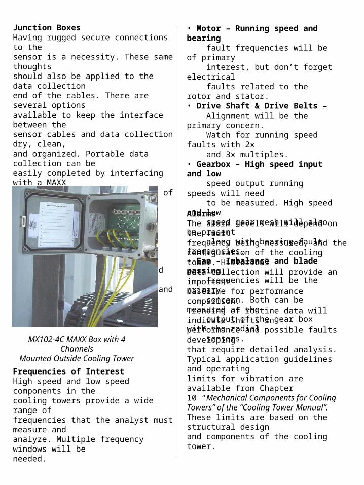
Junction BoxesHaving rugged secure connections to thesensor is a necessity. These same thoughtsshould also be applied to the data collectionend of the cables. There are several optionsavailable to keep the interface between thesensor cables and data collection dry, clean,and organized. Portable data collection can beeasily completed by interfacing with a MAXXBox or with a Switch Box. Both of theseoptions provide convenient connections for thedata collector cable. In permanent monitoring,a Switch Box or a Signal management Box canbe used. No matter which method is chosen, itwill prevent wiring spaghetti and organize yourdata collection points.
MX102-4C MAXX Box with 4 Channels
Mounted Outside Cooling Tower
Frequencies of InterestHigh speed and low speed components in thecooling towers provide a wide range offrequencies that the analyst must measure andanalyze. Multiple frequency windows will beneeded.
• Motor – Running speed and bearing fault frequencies will be of primary interest, but don’t forget electrical faults related to the rotor and stator.• Drive Shaft & Drive Belts – Alignment will be the primary concern. Watch for running speed faults with 2x and 3x multiples.• Gearbox – High speed input and low speed output running speeds will need to be measured. High speed and low speed gear mesh will also be present along with bearing fault frequencies.• Fan – Imbalance and blade passing frequencies will be the primary concern. Both can be measured at the output of the gear box with the radial sensors.
AlarmsThe alarm levels will depend on the faultfrequency being measured, and theconfiguration of the cooling tower. Historicaldata collection will provide an importantbaseline for performance comparison.Trending of routine data will indicate shifts inperformance and possible faults developingthat require detailed analysis.Typical application guidelines and operatinglimits for vibration are available from Chapter10 “Mechanical Components for CoolingTowers” of the “Cooling Tower Manual”.These limits are based on the structural designand components of the cooling tower.