viber-a manual - vibrasyon
TRANSCRIPT
Viber-A Manual Viber-A Manual
VMI AB Torsgatan 1 S-603 63 Norrköping, Sweden Tel. 011-311667 Fax. 011-311678 e-mail: [email protected]
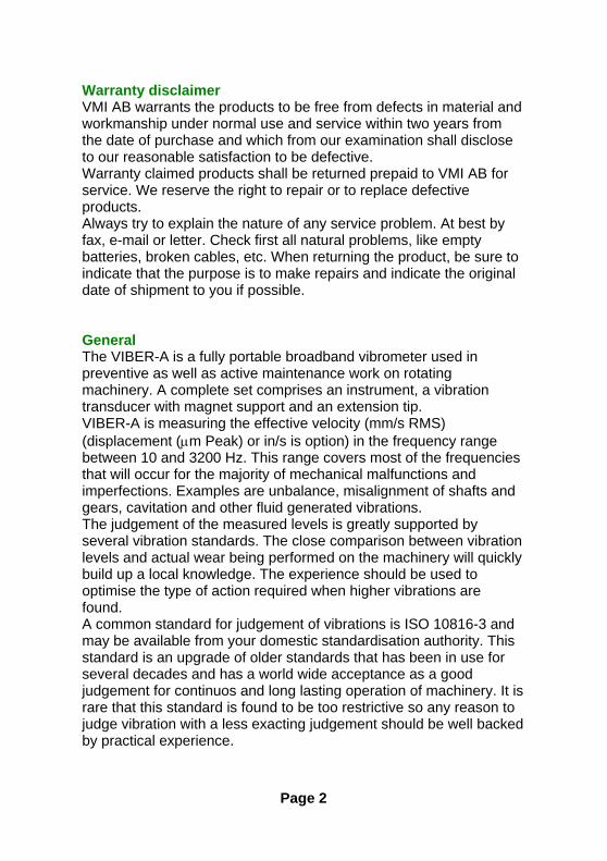
Warranty disclaimer VMI AB warrants the products to be free from defects in material and workmanship under normal use and service within two years from the date of purchase and which from our examination shall disclose to our reasonable satisfaction to be defective. Warranty claimed products shall be returned prepaid to VMI AB for service. We reserve the right to repair or to replace defective products. Always try to explain the nature of any service problem. At best by fax, e-mail or letter. Check first all natural problems, like empty batteries, broken cables, etc. When returning the product, be sure to indicate that the purpose is to make repairs and indicate the original date of shipment to you if possible. General The VIBER-A is a fully portable broadband vibrometer used in preventive as well as active maintenance work on rotating machinery. A complete set comprises an instrument, a vibration transducer with magnet support and an extension tip. VIBER-A is measuring the effective velocity (mm/s RMS) (displacement (µm Peak) or in/s is option) in the frequency range between 10 and 3200 Hz. This range covers most of the frequencies that will occur for the majority of mechanical malfunctions and imperfections. Examples are unbalance, misalignment of shafts and gears, cavitation and other fluid generated vibrations. The judgement of the measured levels is greatly supported by several vibration standards. The close comparison between vibration levels and actual wear being performed on the machinery will quickly build up a local knowledge. The experience should be used to optimise the type of action required when higher vibrations are found. A common standard for judgement of vibrations is ISO 10816-3 and may be available from your domestic standardisation authority. This standard is an upgrade of older standards that has been in use for several decades and has a world wide acceptance as a good judgement for continuos and long lasting operation of machinery. It is rare that this standard is found to be too restrictive so any reason to judge vibration with a less exacting judgement should be well backed by practical experience.
Page 2
Functions
Start of the instrument Press this symbol key and the instrument starts to measure. The instrument will be shut off automatically after approximately 2,5 minutes.
Battery check Press this symbol key and keep it pressed and the instrument shows the battery voltage. Change the battery when the voltage is below 7 volts. The battery capacity of an ordinary type is enough for approximately 20 hours of constant operation or 350 measurement. The battery capacity of an alkaline type is enough for approximately 40 hours of constant operation or 1000 measurement.
Bearing condition Press this symbol key and keep it pressed. The instrument measures instantaneously a bearing condition value in the range between 3.200Hz to 20.000Hz.
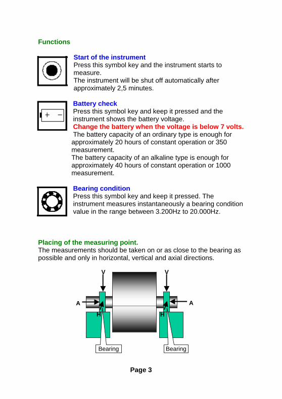
Placing of the measuring point. The measurements should be taken on or as close to the bearing as possible and only in horizontal, vertical and axial directions.
Bearing Bearing
V
H H
V
A A
Page 3
How to make good measurements. The sensitivity direction of the transducer coincides with the centre axis of the transducer. The transducer end (with the M6 stud) is pushed firmly against the measurement point. The main purpose is to make the complete transducer to fully participate in the motion of the measurement point. Try to hold the transducer in a vertical, horizontal or axial direction as possible, even if the machine surface does not have these directions. Read the instrument held with the free hand. Note a stable reading as well as a fluctuating one, since the fluctuation itself is a valuable information regarding the reason for the vibration. When the transducer is mounted with the magnet the frequency range of the measurement is reduced to about 2.000 to 3.000Hz depending on the flatness of the measuring surface. When the measuring tip is used the frequency range is reduced to about 800 to 1500Hz. Note When using the magnet or the measuring tip the bearing condition value can be substantially changed. Use the M6 stud on the transducer for high frequency measurements. Vibrations at high frequencies can sometimes cause measurement problems. Pressing the transducer more firmly should not change the reading. If in doubt, always try to adjust the contact point first. Secondly, if shown to be necessary, mount the transducer with the M6 stud. All normal measurements on vertical or horizontal machinery should follow the three perpendicular axis of true vertical, horizontal and axial directions. The reason is that you should keep to the main stiffness directions caused by normal non symmetrical properties of the foundation, piping, supports etc. It will result in better understanding if the basic measurements are made in this way.
Page 4
The VIBER-A is mainly intended for measurements against the housing and bearings of machinery according to the intentions of the standards. You can also use it to measure other parts such as piping, valves, etc. Note that in some cases the mass of the transducer may influence the reading. A good rule is to consider readings on surfaces that are lower in mass than 10 times the mass of the transducer doubtful. How to interpret vibration measurements. A user with no previous experience to interpret the results is recommended to use the ISO 10816-3 standard together with a good portion of common sense. Be prepared to find exemptions making the judgements harder than the standards, rather than finding exemptions allowing for higher vibrations. The standard normally calls for a measure in velocity based on mm/s RMS. To better understand what this measure means it can be helpful to consider the reading as a mean value of the back and forward motion. This measure gives a good understanding of the amount of "break down energy", causing mainly wear and fatigue work, in the machine or the structure being measured. The instrument is measuring the total RMS-value of the vibration within the instrument frequency range. This RMS-value is a special sum or average of all the different causes of vibration. EXAMPLE: If the simultaneous vibration caused by unbalance is (4mm/s), by misalignment (2 mm/s) and by the gearmesh (5 mm/s) then the total vibration measured on the VIBER-A is 6.7 mm/s. Total vibration =
Page 5
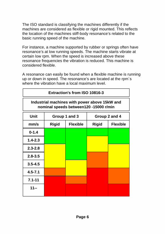
The ISO standard is classifying the machines differently if the machines are considered as flexible or rigid mounted. This reflects the location of the machines stiff-body resonance’s related to the basic running speed of the machine. For instance, a machine supported by rubber or springs often have resonance’s at low running speeds. The machine starts vibrate at certain low rpm. When the speed is increased above these resonance frequencies the vibration is reduced. This machine is considered flexible. A resonance can easily be found when a flexible machine is running up or down in speed. The resonance’s are located at the rpm´s where the vibration have a local maximum level.
Rigid Flexible Rigid Flexible
Group 1 and 3 Group 2 and 4
Industrial machines with power above 15kW andnominal speeds between120 -15000 r/min
mm/s
Unit
0-1.4
1.4-2.3
2.3-2.8
2.8-3.5
3.5-4.5
4.5-7.1
7.1-11
11--
Extraction's from ISO 10816-3
Page 6
Modern machines have high rpm´s and flexible bearing-supports and foundations and can be treated as flexible even when it is not mounted on rubber or springs. The ISO 10816-3 standard allows for slightly higher limits when a foundation is considered flexible than when if it is rigid. A conclusion from this is also that a resonant condition in principle is not allowed or at least should be avoided at operating speeds. In practice this also includes the double speed as well as any other natural excitation frequency such as blade passage etc. A great advantage with proper vibration measurements and the use of vibration standards is that you can judge the future maintenance cost very reliably already at first start-up. If you find levels above 3 mm/s RMS, you can be rather sure that the machine will cause increased activities in maintenance. The specific cost and action is of course individual to the machine design. As always when using schematic judgement like this, be very careful to use common sense in the application of the recommendations. A certain machine is producing its specific vibration frequency pattern depending on the transducer location and the machine properties. The next logical step is therefore to apply filtering of the transducer signal to learn the frequency behind the vibration and thus the exact mechanical fault. The practice of this is beyond the scope of this manual. Looseness By measuring the vibration on both sides of a bolt joint it is possible to find loosness in the connection. Two machine parts joined together should have the same vibration level on both sides of the joint. Bolts fixed in concrete foundations should have the same vibration level as the concrete if they are not loose.
Page 7
Recommended vibration levels in mm/s an common findings. The following is in part an extraction of the old standard ISO 2372 class 4, large machines on flexible foundations, with some common findings added. This simplified list can be used, as a first consideration, when you approach a machine newly commissioned or after some time in operation. Take as a good housekeeping rule to investigate the reason for any machine that vibrates above 3 mm/s RMS. Do not leave them above 7mm/s without being assured that they will sustain long term operation without increased wear since the machines capable of that are very few. • 0 – 3 mm/s Small vibrations. None or very small bearing wear. Rather low noise level. • 3 – 7 mm/s Noticeable vibration levels often concentrated to some specific part as well as direction of the machine. Noticeable bearing wear. Seal problems occur in pumps etc. Increased noise level. Try to investigate the reason. Plan action during next regular stop. Keep the machine under observation and measure at smaller time intervals than before to detect a deterioration trend if any. Compare vibrations to other operating variables. • 7 – 18 mm/s Large vibrations. Bearings running hot. Bearing wear-out cause frequent replacements. Seals wear out, leakage of all kinds evident. Cracks in weldings and concrete foundations. Screws and bolts are loosening. High noise level. Plan action soonest. Do your best to reveal the reason. You are wearing down investments quickly. • 18 – mm/s Very large vibrations and high noise levels. This is detrimental to the safe operation of the machine. Stop operation if technically or economically possible considering the plant stop cost. No known machine will withstand this level without internal or external damage. Reduce any further running time to an absolute minimum.
Page 8
Resonance When working with vibrations in machine maintenance, you will soon find that resonance is a common but rather unknown problem in modern machinery. To understand a resonance you can compare with the string of a guitar. The string has its natural basic tune that will ring as soon as the string is struck. The actual frequency of the tune depends on the stiffness and the distributed mass of the string. All machines have similar built in "tunes" with corresponding properties consisting of stiffness and mass in the form of mechanical strings such as shafts, beams, floors and in all mechanical parts. If any natural excitation (= alternating force) in the machine has the same or nearly the same frequency as a resonance frequency the vibration will be amplified in this machine part, a much higher level will occur than would be the case if the resonance would be shifted away from the excitation frequency.. One common resonance frequency is the critical speed of a shaft which depends on the stiffness and mass of the shaft, but resonance’s exist in all machine parts as well as in supporting beams and concrete floors. A natural excitation force is for example unbalance at the running speed, misalignment on mainly twice the speed etc. THE BASIC RULE IS THAT THE RESONANCE’S OF ANY PART IN THE MACHINE SHOULD NOT COINCIDE WITH ANY NATURAL IMPULSE IN THE MACHINE. A broad band vibrometer can not recognise the frequencies of the vibration but as a rule most high vibrations are caused by only one mechanical problem.
Page 9
To identify the presence of a resonance, measure the vibration levels in three perpendicular directions at the bearings. If you find a measurement with at least three times higher level than in the other directions you should consider a resonance a likely possibility. The resonance is amplifying the mechanical force and thus gives a high vibration in that direction. The resonance makes the machine unnecessarily sensitive to mechanical forces. It is possible to locate the resonance peak while the speed of the machine is changing. The resonance frequency is located at that rpm where the vibration has a local maximum. The proper action against a resonance is very different depending on its location, operating conditions etc. It will normally require good experience to alter the situation. One reason is that the modification affects the basic mechanical design of the machine and where you normally require the competence of the machine designer. We recommend you however not to hesitate to consider such modifications since the change of the resonance frequency normally is cheap compared to the high maintenance cost that will follow any attempt to run a machine in long term operation under the influence of a resonance. A TEMPORARY AND SOMETIMES PERMANENT SOLUTION TO A RESONANCE PROBLEM IS TO CHANGE THE SHAFT SPEED OF THE MACHINE, IF POSSIBLE.
Page 10
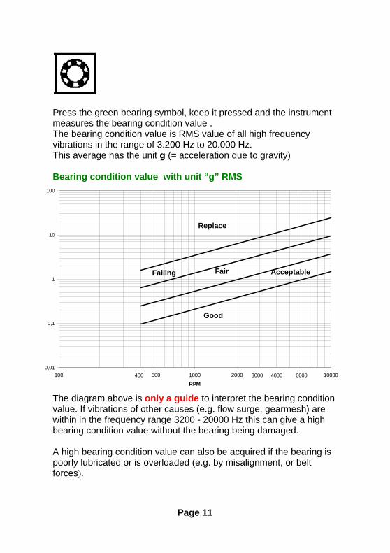
Press the green bearing symbol, keep it pressed and the instrument measures the bearing condition value . The bearing condition value is RMS value of all high frequency vibrations in the range of 3.200 Hz to 20.000 Hz. This average has the unit g (= acceleration due to gravity) Bearing condition value with unit “g” RMS
0,01
0,1
1
10
100
100 1000 10000
RPM2000 3000400 60004000500
Good
AcceptableFairFailing
Replace
The diagram above is only a guide to interpret the bearing condition value. If vibrations of other causes (e.g. flow surge, gearmesh) are within in the frequency range 3200 - 20000 Hz this can give a high bearing condition value without the bearing being damaged. A high bearing condition value can also be acquired if the bearing is poorly lubricated or is overloaded (e.g. by misalignment, or belt forces).
Page 11
What is a bearing condition value? The bearing condition value in Viber-A is the sum average value, RMS value, of all high frequency vibrations between 3200 Hz to 20000 Hz. This value is an acceleration average with the unit "g" because high frequencies give a large signal if it is measured in acceleration. When the balls or rollers rotate inside the bearing a wide-band noise and vibration arises. This noise and vibration are increased if the bearing is poorly lubricated, overloaded due to misalignment or has a damaged surface. Because this is a wide-band noise and vibration it is possible to select any frequency or frequency band as a measurement of bearing condition. If the selected frequency band includes low frequencies the bearing condition value would also include vibrations from unbalances, misalignment, etc., and not purely from bearing vibrations and would therefor be difficult to interpret. If the selected frequency band only includes very high frequency noise and vibrations we would need special vibration transducers that are very rigidly and closely mounted to the bearing because the machine structure works as a mechanical filter for high frequencies. VIBER-A is measuring the bearing condition value between 3200 Hz to 20000 Hz, similar to many other instruments. Within this frequency range there exist a common experience in the evaluation of the bearing condition level. Normal machinery vibrations such as unbalance, misalignment, etc., rarely has vibrations above 3200 Hz. The upper frequency limit of 20.000 Hz is selected because most vibration transducers have an upper frequency limit of about 7000 Hz, without special mounting arrangements, and the transducer signal is very low above 20000Hz. NOTE! A high bearing condition value should always be used as a request to make frequency analysis. High bearing condition values can appear at gear boxes, converting machines with cutters and similar machines without any bearing faults because they "naturally" produce frequencies above 3200 Hz.
Page 12
Balancing with VIBER-A It is only possible to balance machines where the unbalance is the major cause of vibration. Do not change the position of the vibration transducer after the start of the balancing procedure. Balancing using this method requires only three consecutive trial runs and changing the balance status of the rotor. Only measurement of the vibration level is needed. Balancing will of course only reduce the vibration caused by unbalance. A balancing round will often be a good approach and a first attempt to find the reason for increased vibration. If the balancing attempt is not successful, the cause can be loose rotor parts etc. If the machine speed is variable, be sure to choose the same speed during every trial run. Do not search the speed that gives the highest vibration. Such speeds mostly show non-linear results. Start the procedure by measuring on the bearings looking for high levels in major directions. Choose a point that should have a good connection to a balancing plane where you can put in a weight in the machine. You must use the same radius for the trial weights and the balancing weights.
Page 13
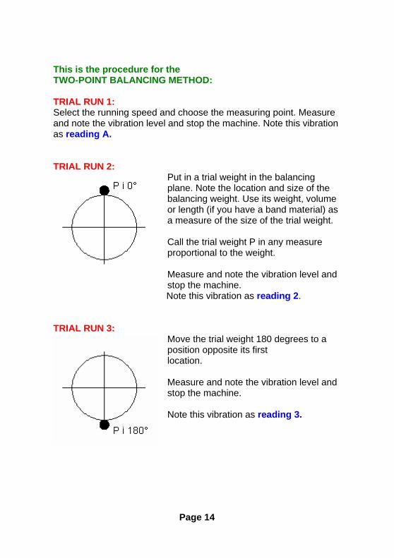
This is the procedure for the TWO-POINT BALANCING METHOD: TRIAL RUN 1: Select the running speed and choose the measuring point. Measure and note the vibration level and stop the machine. Note this vibration as reading A. TRIAL RUN 2:
Put in a trial weight in the balancing plane. Note the location and size of the balancing weight. Use its weight, volume or length (if you have a band material) as a measure of the size of the trial weight.
Call the trial weight P in any measure proportional to the weight. Measure and note the vibration level and stop the machine. Note this vibration as reading 2.
TRIAL RUN 3:
Move the trial weight 180 degrees to a position opposite its first location. Measure and note the vibration level and stop the machine. Note this vibration as reading 3.
Page 14
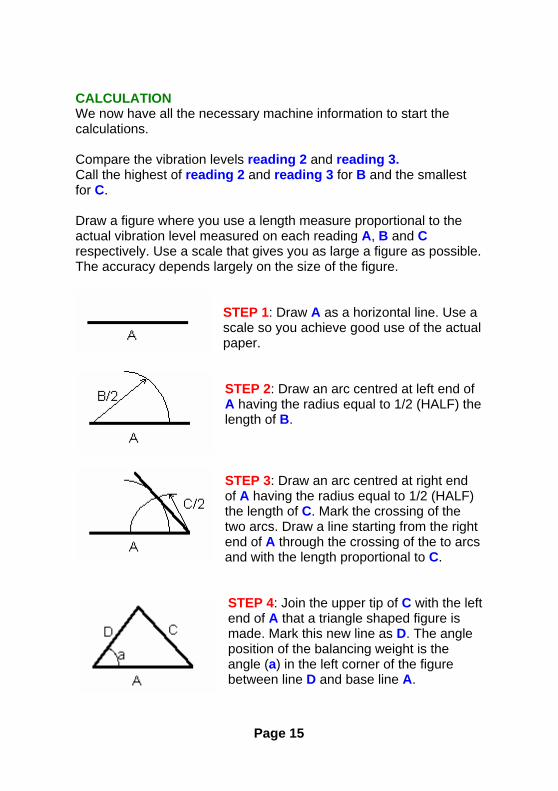
CALCULATION We now have all the necessary machine information to start the calculations. Compare the vibration levels reading 2 and reading 3. Call the highest of reading 2 and reading 3 for B and the smallest for C. Draw a figure where you use a length measure proportional to the actual vibration level measured on each reading A, B and C respectively. Use a scale that gives you as large a figure as possible. The accuracy depends largely on the size of the figure.
STEP 1: Draw A as a horizontal line. Use a scale so you achieve good use of the actual paper. STEP 2: Draw an arc centred at left end of A having the radius equal to 1/2 (HALF) the length of B. STEP 3: Draw an arc centred at right end of A having the radius equal to 1/2 (HALF) the length of C. Mark the crossing of the two arcs. Draw a line starting from the right end of A through the crossing of the to arcs and with the length proportional to C.
STEP 4: Join the upper tip of C with the left end of A that a triangle shaped figure is made. Mark this new line as D. The angle position of the balancing weight is the angle (a) in the left corner of the figure between line D and base line A.
Page 15

THE SIZE OF THE BALANCING WEIGHT The SIZE of the balancing weight that you should put on the balancing plane is proportional to the size of the trial weight with the same relation as the line A to D in the figure. In other words: trial weight P * the length of A Balancing weight BW = ------------------------------------------ the length of D You can measure A and D in the figure. You may soon realise that best results are obtained when the triangle has approximately equal sides. THE ANGLE POSITION OF THE BALANCING WEIGHT
When we had the trial weight in position C we had a lower vibration than in position B. The trial weight in position C must therefore be on the proper half of the rotor. The balancing weight should be positioned (a) degrees from the position of the trial weight C.
The angle (a) can be measured on your rotor in either the direction against or with rotation. You must make a qualified guess and try one alternative. If the vibration is not reduced the other location may be the better. The balancing may be stopped when the highest radial direction is below 3 mm/s rms.
Page 16

MISCELLANEOUS If you prefer to calculate the balancing weight, this is the formula:
TROUBLE HINTS The most difficult task in balancing is to guess a suitable size of the trial weight because we do not know the unbalance sensitivity of the machine. The whole balancing procedure depends on the changes in vibration level that occur when we add a trial weight. If the trial weight is too small compared to the unbalance we cannot measure any changes in the vibration levels and the measurements A, B and C become almost equal. The triangle in our figure becomes flat. If the trial weight is too large compared to the unbalance the measurements B and C become very large compared to the measurement A and the triangle in our figure becomes very high and narrow. This produces an uncertainty in our calculations. If the triangle cannot be formed well, use the results to guess a better trial weight size or try a location of the trial weight a quarter turn away from the first position. If the triangle cannot be formed at all there are often two major reasons:
1. Something is loose. Check the fit between the rotor and shaft. Check bolt joints. Is dirt gradually falling off during each run?
2. The vibration does not depend on unbalance. You are trying to balance a machine where the unbalance is very small and where the vibration comes from other faults. E.g. misalignment, gearbox, cavitation in pumps etc.
Page 17
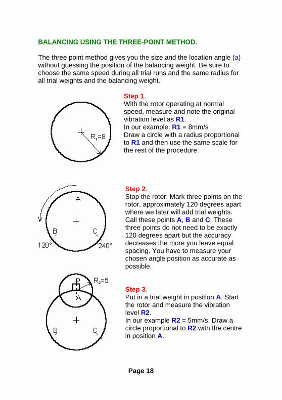
BALANCING USING THE THREE-POINT METHOD. The three point method gives you the size and the location angle (a) without guessing the position of the balancing weight. Be sure to choose the same speed during all trial runs and the same radius for all trial weights and the balancing weight.
Step 1. With the rotor operating at normal speed, measure and note the original vibration level as R1. In our example: R1 = 8mm/s Draw a circle with a radius proportional to R1 and then use the same scale for the rest of the procedure. Step 2. Stop the rotor. Mark three points on the rotor, approximately 120 degrees apart where we later will add trial weights. Call these points A, B and C. These three points do not need to be exactly 120 degrees apart but the accuracy decreases the more you leave equal spacing. You have to measure your chosen angle position as accurate as possible. Step 3. Put in a trial weight in position A. Start the rotor and measure the vibration level R2. In our example R2 = 5mm/s. Draw a circle proportional to R2 with the centre in position A.
Page 18
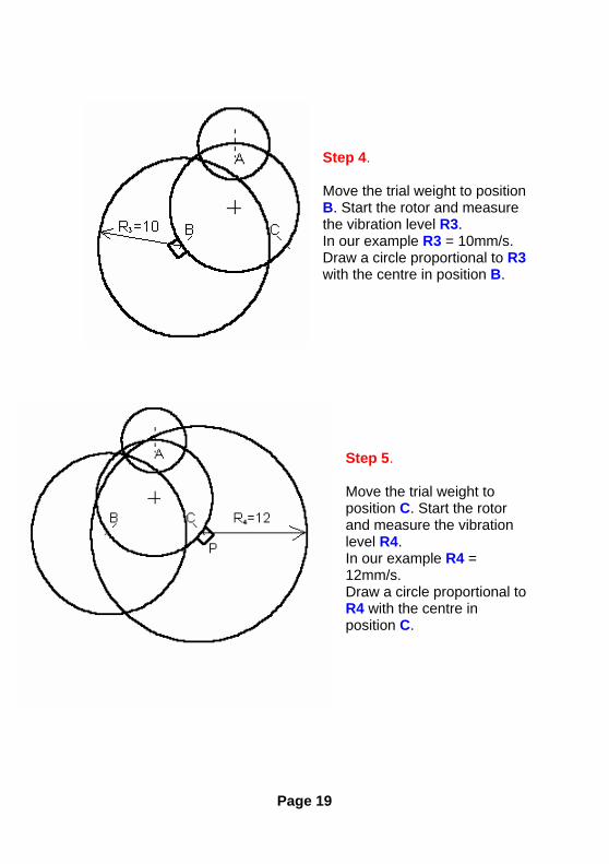
Step 4. Move the trial weight to position B. Start the rotor and measure the vibration level R3. In our example R3 = 10mm/s. Draw a circle proportional to R3 with the centre in position B.
Step 5. Move the trial weight to position C. Start the rotor and measure the vibration level R4. In our example R4 = 12mm/s. Draw a circle proportional to R4 with the centre in position C.
Page 19
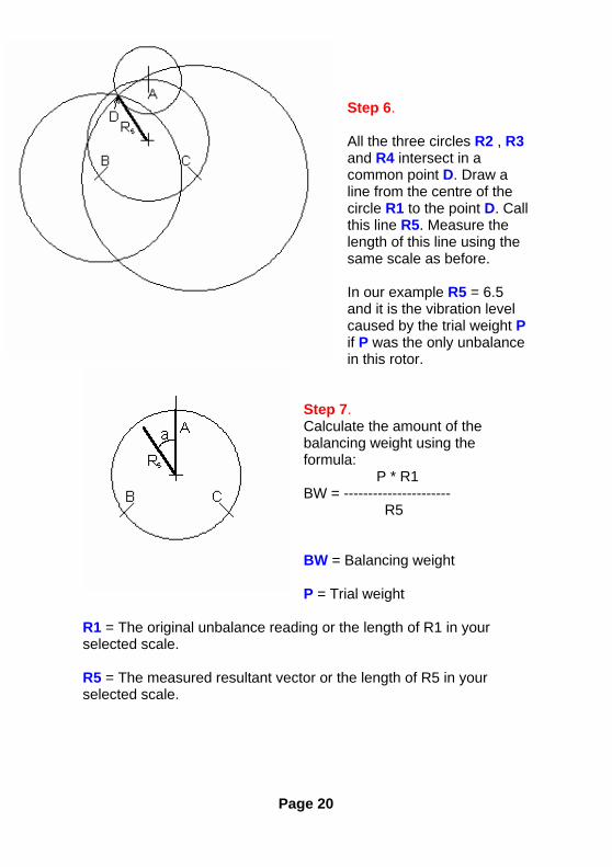
Step 6. All the three circles R2 , R3 and R4 intersect in a common point D. Draw a line from the centre of the circle R1 to the point D. Call this line R5. Measure the length of this line using the same scale as before. In our example R5 = 6.5 and it is the vibration level caused by the trial weight P if P was the only unbalance in this rotor.
Step 7. Calculate the amount of the balancing weight using the formula: P * R1 BW = ---------------------- R5 BW = Balancing weight P = Trial weight
R1 = The original unbalance reading or the length of R1 in your selected scale. R5 = The measured resultant vector or the length of R5 in your selected scale.
Page 20
If in our example the trial weight P = 87 grams then the balancing weight will be: 87 * 8 BW = ------------- = 107 grammes 6.5 Use a protractor to measure the angle between R5 and A. This angle is also the angular position of the balance weight relative to positon A in the rotor. In our example the measured angle a = 37 degrees. In our example we should add a balancing weight of 107 grams in the angle 37 degrees away from position A in the direction towards B in the rotor.
Page 21
TECHNICAL SPECIFICATIONS VIBER-A INPUT SENSITIVITY: 100mV/g calibrated at 156,15 Hz. MEASURING RANGE: Velocity: 0-200 mm/s RMS FREQUENCY RANGE: Total level 10-3200Hz, options : 2-3200Hz, 10-1000Hz Bearing condition 3200Hz - 20000Hz The measurement mainly follows ISO 2954, to conform with the new vibration standard ISO10816-3. If the instrument as to conform with the older vibration standard ISO2374 the instrument has to be ordered with the optional frequency range 10-1000Hz. BATTERY TYPE: 9V 6F22 or similar VIBRATION TRANSDUCER The accelerometer IMI608A11 has a sensitivity 100mV/g +/-10%. MAGNET SUPPORT Length: 20mm, Diameter: 15mm, Magnet force: about 14kg. EXTENSION TIP Length: 65mm
Page 22