vhdl language · 2003-11-17 · 1. vhdl 개요 1.1 vhdl 역사 1) 설계의 복잡도가...
TRANSCRIPT
VHDL Language 요약
2000. 2
연 세 대 학 교
기전 공학부 전기 전공
김 재 석 교 수
- Page 1 -
목 차
1. VHDL 개요
1.1 VHDL 역사 ----------------------------------------------------------------------------- 1 1.2 VHDL 특징 ----------------------------------------------------------------------------- 1
2. VHDL 기본 개념
2.1 기본 개념 ------------------------------------------------------------------------------- 2 2.2 Entity declaration --------------------------------------------------------------------- 3 2.3 Architecture body --------------------------------------------------------------------- 4 2.4 Configuration declaration ----------------------------------------------------------- 8 2.5 Package declaration & package body ------------------------------------------- 9 2.6 Design library --------------------------------------------------------------------------11 2.7 VHDL Simulation ----------------------------------------------------------------------12
3. 기본적인 Language Elements
3.1 Lexical Elements ----------------------------------------------------------------------13 3.2 Data Objects ---------------------------------------------------------------------------14 3.3 Data Types -----------------------------------------------------------------------------15 3.4 Operators -------------------------------------------------------------------------------21
4. Behavioral Modeling
4.1 Process Statement -------------------------------------------------------------------22 4.2 Variable assignment Statement ---------------------------------------------------23 4.3 Signal assignment Statement -----------------------------------------------------23 4.4 Wait Statement ------------------------------------------------------------------------24 4.5 If Statement ----------------------------------------------------------------------------25 4.6 Case Statement -----------------------------------------------------------------------26 4.7 Loop Statement -----------------------------------------------------------------------27 4.8 Exit Statement -------------------------------------------------------------------------28 4.9 Next Statement ------------------------------------------------------------------------28 4.10 Null Statement -----------------------------------------------------------------------29 4.11 Assertion Statement ----------------------------------------------------------------29 4.12 Delay models -------------------------------------------------------------------------30 4.13 More on signal assignment in a process --------------------------------------31 4.14 Multiple process & process communication ----------------------------------33
- Page 2 -
5. Dataflow Modeling 5.1 Concurrent signal assignment Statement --------------------------------------35 5.2 Conditional signal assignment Statement --------------------------------------36 5.3 Selected signal assignment Statement -----------------------------------------37 5.4 Multiple driver - resolution function ----------------------------------------------38
6. Structural Modeling
6.1 Component declaration -------------------------------------------------------------39 6.2 Component instantiation ------------------------------------------------------------40 6.3 Generics --------------------------------------------------------------------------------41 6.4 Configuration Specification ---------------------------------------------------------42
7. Subprogram & Overloading 7.1 Function ---------------------------------------------------------------------------------43 7.2 Procedure -------------------------------------------------------------------------------44 7.3 Subprogram overloading -----------------------------------------------------------45 7.4 Operator overloading ----------------------------------------------------------------46
8. Advanced Features
8.1 Entity statement -----------------------------------------------------------------------47 8.2 Generate statement ------------------------------------------------------------------48 8.3 Block statement -----------------------------------------------------------------------50 8.4 Guarded signal ------------------------------------------------------------------------52 8.5 Aliases -----------------------------------------------------------------------------------53 8.6 Attributes --------------------------------------------------------------------------------53
9. Modeling Techniques
9.1 Design Library 선정 ------------------------------------------------------------------58 9.2 Test Bench의 작성 ------------------------------------------------------------------59
Appendix A. Reserved Keywords ------------------------------------------------63 Bibliography ----------------------------------------------------------------------------------64
- Page 3 -
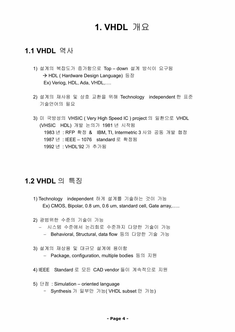
1. VHDL 개요
1.1 VHDL 역사
1) 설계의 복잡도가 증가함으로 Top – down 설계 방식이 요구됨 HDL ( Hardware Design Language) 등장
Ex) Veriog, HDL, Ada, VHDL,….
2) 설계의 재사용 및 상호 교환을 위해 Technology independent한 표준 기술언어의 필요
3) 미 국방성의 VHSIC ( Very High Speed IC ) project의 일환으로 VHDL
(VHSIC HDL) 개발 논의가 1981년 시작됨 1983년 : RFP 확정 & IBM, TI, Intermetric 3사와 공동 개발 협정 1987년 : IEEE – 1076 standard로 확정됨 1992년 : VHDL‘92가 추가됨
1.2 VHDL의 특징
1) Technology independent 하게 설계를 기술하는 것이 가능 Ex) CMOS, Bipolar, 0.8 um, 0.6 um, standard cell, Gate array,…..
2) 광범위한 수준의 기술이 가능
− 시스템 수준에서 논리회로 수준까지 다양한 기술이 가능 − Behavioral, Structural, data flow 등의 다양한 기술 가능
3) 설계의 재상용 및 대규모 설계에 용이함 − Package, configuration, multiple bodies 등의 지원
4) IEEE Standard로 모든 CAD vendor들이 계속적으로 지원 5) 단점 : Simulation – oriented language
- Synthesis가 일부만 가능( VHDL subset만 가능)
- Page 4 -
2. VHDL 기본 개념
2.1기본개념
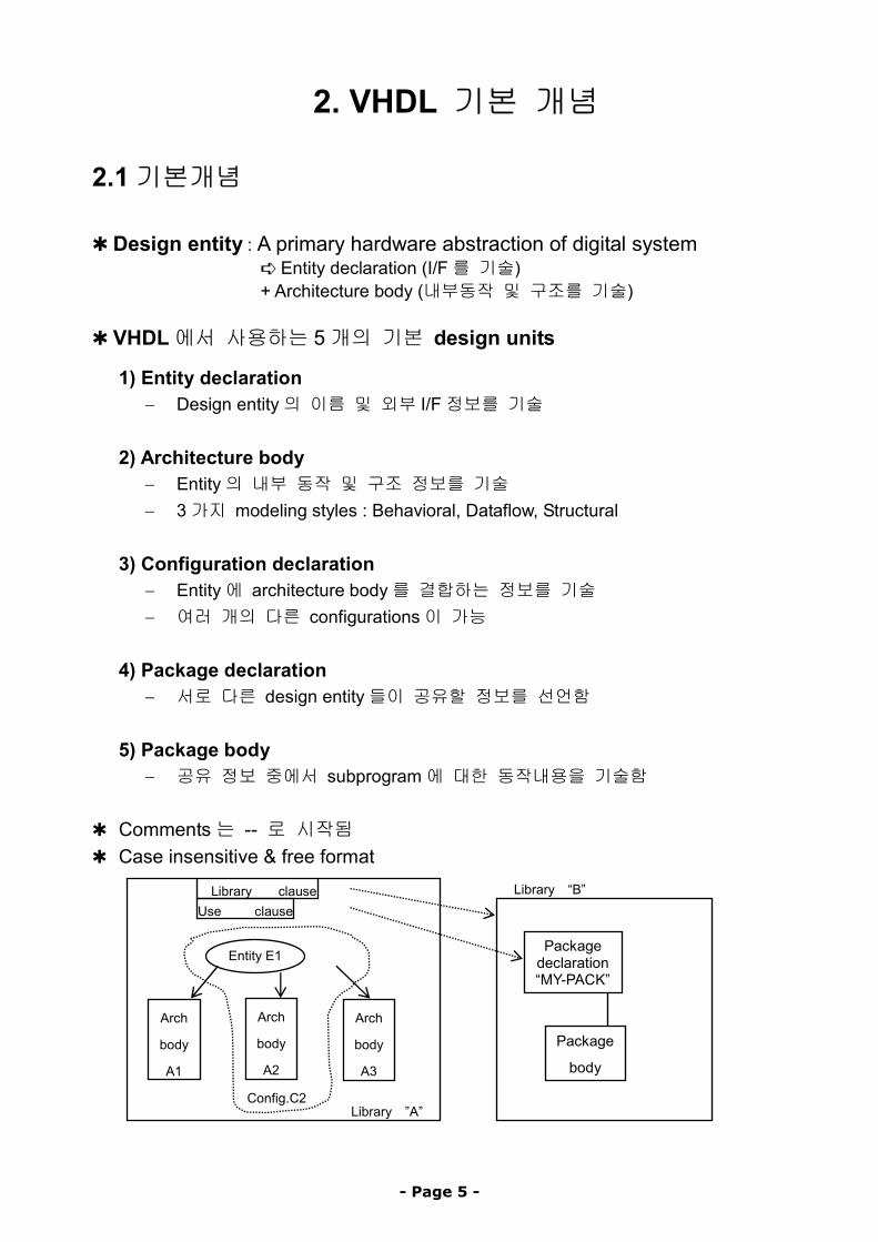
✱ Design entity : A primary hardware abstraction of digital system ➪ Entity declaration (I/F를 기술) + Architecture body (내부동작 및 구조를 기술)
✱ VHDL에서 사용하는 5개의 기본 design units
1) Entity declaration − Design entity의 이름 및 외부 I/F정보를 기술
2) Architecture body − Entity의 내부 동작 및 구조 정보를 기술 − 3가지 modeling styles : Behavioral, Dataflow, Structural
3) Configuration declaration − Entity에 architecture body를 결합하는 정보를 기술 − 여러 개의 다른 configurations이 가능
4) Package declaration − 서로 다른 design entity들이 공유할 정보를 선언함
5) Package body − 공유 정보 중에서 subprogram에 대한 동작내용을 기술함
✱ Comments는 -- 로 시작됨 ✱ Case insensitive & free format
Arch
body
A2
Library “B”
Package
body
Packagedeclaration“MY-PACK”
Library ”A”Config.C2
Arch
body
A1
Arch
body
A3
Entity E1
Use clause Library clause
- Page 5 -
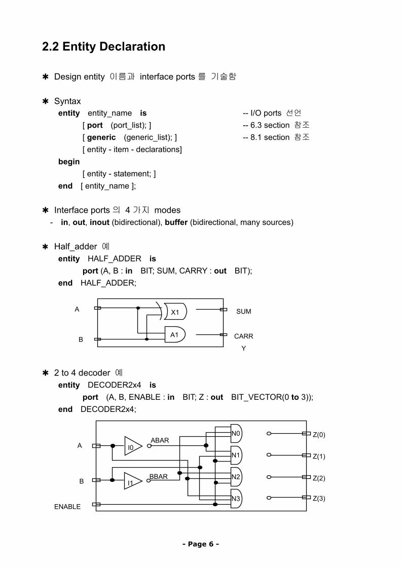
2.2 Entity Declaration
✱ Design entity 이름과 interface ports를 기술함
✱ Syntax entity entity_name is -- I/O ports 선언
[ port (port_list); ] -- 6.3 section 참조 [ generic (generic_list); ] -- 8.1 section 참조 [ entity - item - declarations]
begin [ entity - statement; ]
end [ entity_name ]; ✱ Interface ports의 4가지 modes
- in, out, inout (bidirectional), buffer (bidirectional, many sources)
✱ Half_adder 예 entity HALF_ADDER is
port (A, B : in BIT; SUM, CARRY : out BIT); end HALF_ADDER;
A1
X1A SUM
CARR
Y B
✱ 2 to 4 decoder 예
entity DECODER2x4 is port (A, B, ENABLE : in BIT; Z : out BIT_VECTOR(0 to 3));
end DECODER2x4;
BBAR
ABAR
I1
I0
N0
N3
N2
N1
Z(0) A
Z(1)
Z(2) B
Z(3) ENABLE
- Page 6 -
2.3 Architecture Body
✱ Design entity의 내부 기능 및 구조를 기술 ✱ 아래의 3가지 modeling styles 가능
1) Behavioral description ( as s set of sequential assignment statements) 2) Dataflow description (as a set of concurrent assignment statements) 3) Structural description (as a set of interconnected components)
✱ Syntax architecture arch_name of entity_name is
{ arch_declarative_item } -- signal or component 선언 등 begin
{ concurrent statements } -- 아래의 concurrent statements 들 end [ arch_name ];
✱ Concurrent statements : 순서에 관계없이 병렬로 수행되는 statement 들 - Processing statement - Concurrent signal assignment statement - Concurrent assertion statement - Concurrent procedure call - Component instantiation statement - Block statement - Generate statement
- Page 7 -
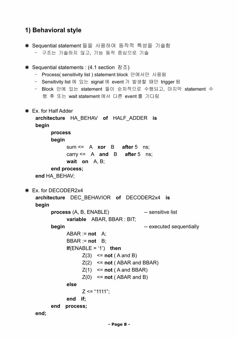
1) Behavioral style
✱ Sequential statement들을 사용하여 동작적 특성을 기술함 - 구조는 기술하지 않고, 기능 동작 중심으로 기술
✱ Sequential statements : (4.1 section 참조) - Process( sensitivity list ) statement block 안에서만 사용됨 - Sensitivity list에 있는 signal에 event가 발생할 때만 trigger됨 - Block 안에 있는 statement 들이 순차적으로 수행되고, 마지막 statement 수행 후 또는 wait statement에서 다른 event를 기다림
✱ Ex. for Half Adder
architecture HA_BEHAV of HALF_ADDER is begin
process begin
sum <= A xor B after 5 ns; carry <= A and B after 5 ns; wait on A, B;
end process; end HA_BEHAV;
✱ Ex. for DECODER2x4 architecture DEC_BEHAVIOR of DECODER2x4 is begin
process (A, B, ENABLE) -- sensitive list variable ABAR, BBAR : BIT;
begin -- executed sequentially ABAR := not A; BBAR := not B; If(ENABLE = ‘1’) then
Z(3) <= not ( A and B) Z(2) <= not ( ABAR and BBAR) Z(1) <= not ( A and BBAR) Z(0) <= not ( ABAR and B)
else Z <= “1111”;
end if; end process;
end;
- Page 8 -
2) Dataflow style
✱ Concurrent signal assignment statement들을 사용하여 동작 특성을 기술함 - Entity의 구조가 명확하게 나타나지는 않으나, 유출 가능함
✱ Concurrent signal assignment statements : (section 5.1 참조) - Statement 순서에 상관없이 <= 오른쪽에 있는 signal 에 event 가 발생할 때만 수행됨
✱ Ex. for half adder
architecture HA_CONCURRENT of HALF_ADDER is begin
sum <= A xor B after 8 ns; -- concurrent signal assignment carry <= A and B after 4 ns; -- concurrent signal assignment
end HA_BEHAV; ✱ Ex. for DECODER2x4
architecture DEC_DATAFLOW of DECODER2x4 is signal ABAR,BBAR : BIT
begin Z(3) <= not (A and B and ENABLE); -- s1 Z(0) <= not (ABAR and BBAR and ENABLE); -- s2 BBAR <= not B; -- s3 Z(2) <= not (A and BBAR and ENABLE); -- s4 ABAR <= not A -- s5 Z(1) <= not (ABAR and B and ENABLE); -- s6
end DEC_DATAFLOW;
만약 time T에서 signal B에 event가 발생하면, 1) S1, S2 & S56 will be triggered and evaluated at T+d (delta delay) 2) This will trigger signal BBAR so that s2 & s4 will be triggered and evaluated
at T+2d (2delta delay)
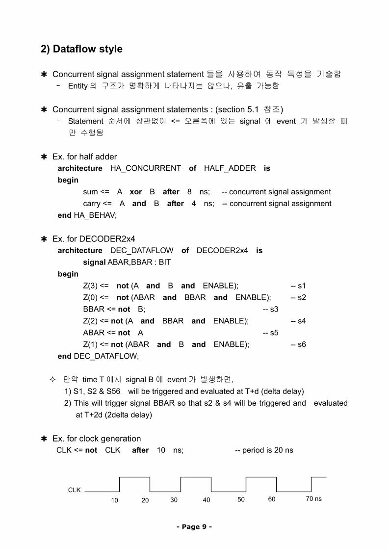
✱ Ex. for clock generation CLK <= not CLK after 10 ns; -- period is 20 ns
CLK 70 ns 60 5030 4010 20
- Page 9 -
3) Structural style
✱ Design entity를 hardware components의 연결 구조로 기술함 ✱ Ex. for half adder
architecture HA_STRUCTURE of HALF_ADDER is component XOR2 -- beginning of declarative part
port(X,Y : in BIT; Z: out BIT); end component; component AND2
port(X,Y : in BIT; Z: out BIT); end component;
begin -- beginning of statement part X1: XOR2 port map(A, B, SUM); A1: AND2 port map(A, B, CARRY);
end HA_STRUCTURE; ✱ Ex. for 2 to 4 decoder
- Page 10 -
2.4 Configuration Declaration
✱ Design entity와 architecture body의 결합(binding) 정보를 기술함 - 하나의 entity에 대해 multiple architecture bodies를 기술하도록 제공. - Top - down design methodology에 유용함
✱ Syntax
configuration configuration-name of entity-name is for block_name
for comp_labels : comp_name [ use binding-indication ]; [ block configuration ]
end for; end for;
end [ configuration-name];
✱ Ex. for HALF ADDER library CMOS_LIB, MY_LIB; -- Two libraries 사용(section 2.6 참조) configuration HA_BINDING of HALF_ADDER is
for HA_STRUCTURE -- architecture 선택 for X1 : XOR2 -- component binding
use entity CMOS_LIB.XOR_GATE(DATAFLOW); end for; for A1 : AND2 -- component binding
use entity MY_LIB.AND_CONFIG; end for; for others: AND2 -- default로 WORK.AND2 사용 end for;
end for; end HA_BINDING;
✱ Hierarchy가 없는(component instantiation이 없는) 경우의 예 configuration DEC_CONFIG of DECODER2x4 is
for DEC_DATAFLOW end for;
end DEC_CONFIG; ✱ Configuration specification을 하는 방법도 있음 (section 6.4 참조)
- Page 11 -
2.5 Package Declaration & Package Body
✱ Package : 여러 design units들이 공통으로 사용할 내용을 담고 있음 ➪ package declaration ( Interface ) + package body ( function body )
1) Package declaration ✱ 서로 다른 design entity들이 공유할 정보(constant, types, signals, attribute,
components, functions, procedures 등)를 선언함 - library &use clause를 사용하여 특정 design unit에 visible하게 만듦 - 재사용을 가능하게 함으로서 중복 설계를 피하게 함
✱ Syntax
package package_name is { package_declarative_item}
end [package_name];
✱ Ex. of package declaration package EXAMPLE_PACK is
constant PIN2PIN_DELAY : TIME := 125 ns; constant TOTAL_ALU : INTEGER; type SUMMER is (JUN, JUL, AUG); component D_FLIP_FLOP
port(D, CLK, : in BIT; Q, QBAR : out BIT); end component; function I2BIT_VEC(INT_V : INTEGER ) return BIT_VECTOR;
end EXAMPLE_PACK;
✱ 특정 entity에서 이 package를 사용하고자 할 때 library DESIGN_LIB; use DESIGN_LIB.EXAMPLE_PACK.all; entity RX is ….
✱ 다른 design unit에서 일부만 사용하고자 할 때 library DESIGN_LIB; use DESIGN_LIB.EXAMPLE_PACK.D_FLIP_FLOP; use DESIGN_LIB.EXAMPLE_PACK.PIN2PIN_DELAY; -- RX entity에서는 위의 두 declaration만 visible함 architecture RX_STRUCTURE of RX is ….
- Page 12 -
2) Package Body
✱ 공유 정보 중 function과 procedure의 body(동작내용)를 기술하거나, deferred constant값을 확정함
- 항상 package declaration과 함께 정의되고, 이름도 서로 동일하여야 함 ✱ Syntax for package body
package body package_name is { package_body_declarative_item }
end [ package_name ]; ✱ Ex. 1
package body EXAMPLE_PACK is constant TOTAL_ALU : INTEGER := 10; function I2BIT_VE C(INT_VALUE : INTEGER) return BIT_VECTOR is begin
-- Behavior of function described here end I2BIT_VEC;
end EXAMPLE_PACK;
✱ Ex. 2 package body ANOTHER_PACKAGE is
function POCKET_MONEY -- Function body (MONTH : DESIGN_LIB.EXAMPLE_PACK.SUMMER) return BIT_VECTOR is
begin case MONTH is
when MAY => return 5; when JUL|AUG => return 6; when others => return 2;
end case end POCKET_MONEY;
end ANOTHER_PACK;
- Page 13 -
2.6 Design Library
1) Design library ✱ Compiled VHDL descriptions이 intermediate 형태로 저장되는 장소 - 모든 design library는 고유한 logical name을 가지고 있음
✱ Pre_defined libraries 1) STD : 두개의 pre_defined packages를 가지고 있음
- STANDARD(VHDL언어의 모든 pre_defined type에 대한 정의 포함) - TEXTIO(ASCII read & write operation을 위한 subprograms을 포함)
2) WORK
- 사용자의 compiled VHDL description이 저장되는 default library ✱ Design library는 library & use clause를 통하여 사용함
2) Library & Use clause ✱ Design library의 logical name을 특정 design unit에서 visible하게 만들어줌 ✱ Format of library clause
library logical_lib_name;
✱ Format of use clause use lib_name.primary_unit_name; use lib_name.primary_unit_name.item;
✱ Ex. 1 : 모든 design unit에 default로 정의 되어 있음 library STD, WORK; use STD.STANDARD.all;
✱ Ex, 2 & 3 library TTL,CMOS; use CMOS.NOR2; Library project_A_lib; use project_A_lib.SYNTH_PACK,all;
- Page 14 -
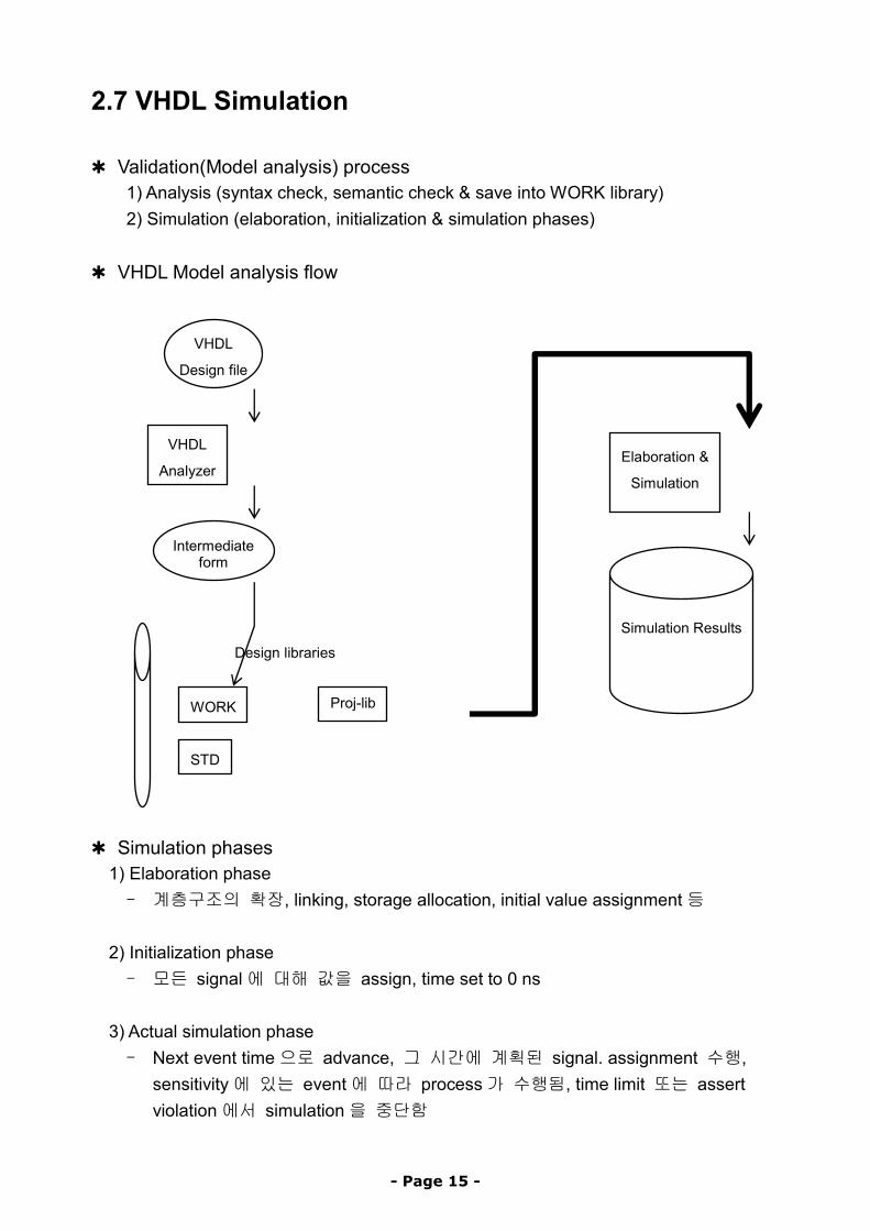
2.7 VHDL Simulation
✱ Validation(Model analysis) process 1) Analysis (syntax check, semantic check & save into WORK library) 2) Simulation (elaboration, initialization & simulation phases)
✱ VHDL Model analysis flow
✱ Simulation phases 1) E aboration phase l
iti
E
Sim tion
Design libraries
Intermediate form
Simulation Results
laboration &
ula
STD
Proj-lib WORK
VHDL
Analyzer
VHDL
Design file
- 계층구조의 확장, linking, storage allocation, initial value assignment등 2) In alization phase - 모든 signal에 대해 값을 assign, time set to 0 ns
3) Actual simulation phase - Next event time으로 advance, 그 시간에 계획된 signal. assignment 수행,
sensitivity에 있는 event에 따라 process가 수행됨, time limit 또는 assert violation에서 simulation을 중단함
- Page 15 -
3. 기본적인 Language Elements
3.1 Lexical Elements
1) Identifier ( Objects의 이름 )
− Characters ( A - Z, a – z, 0 – 9, or _ )의 조합으로 구성
− The first character : should be letter
− The last character : underscore는 안됨
− Case insensitive : lower case & upper case are identical
− A set of reserved keywords : Appendix A
2) Literals
− Integer literals : 0 5634 6E2 98_71( _no impact ) − Floating point literals : 0.0 0.5 16.34 16.2E-2 3_1.4_5
− Based literals : 2#10111# 16#FF# 16#E#E1
− Character literals : ‘A’ ‘3’ ‘_’ ‘’’’( inside two single quotes)
− String literals : “ABC” “double quoted”
− Bit string literals : B”10011111” O”126” X”FF”
− Physical literals : 100 ns 50 sec 10 km
- Page 16 -
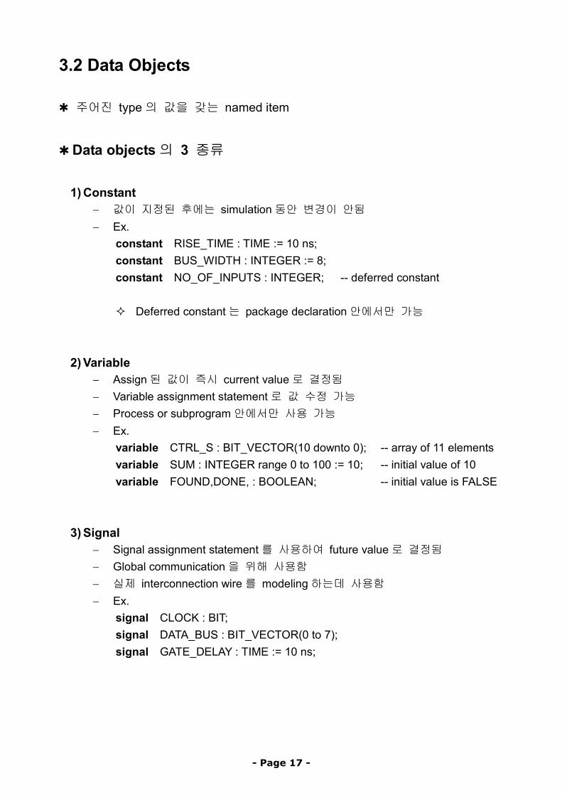
3.2 Data Objects
✱ 주어진 type의 값을 갖는 named item
✱ Data objects의 3 종류
1) Constant
− 값이 지정된 후에는 simulation동안 변경이 안됨 − Ex.
constant RISE_TIME : TIME := 10 ns; constant BUS_WIDTH : INTEGER := 8; constant NO_OF_INPUTS : INTEGER; -- deferred constant
Deferred constant는 package declaration안에서만 가능
2) Variable − Assign된 값이 즉시 current value로 결정됨 − Variable assignment statement로 값 수정 가능 − Process or subprogram안에서만 사용 가능 − Ex.
variable CTRL_S : BIT_VECTOR(10 downto 0); -- array of 11 elements variable SUM : INTEGER range 0 to 100 := 10; -- initial value of 10 variable FOUND,DONE, : BOOLEAN; -- initial value is FALSE
3) Signal − Signal assignment statement를 사용하여 future value로 결정됨 − Global communication을 위해 사용함 − 실제 interconnection wire를 modeling하는데 사용함 − Ex.
signal CLOCK : BIT; signal DATA_BUS : BIT_VECTOR(0 to 7); signal GATE_DELAY : TIME := 10 ns;
- Page 17 -
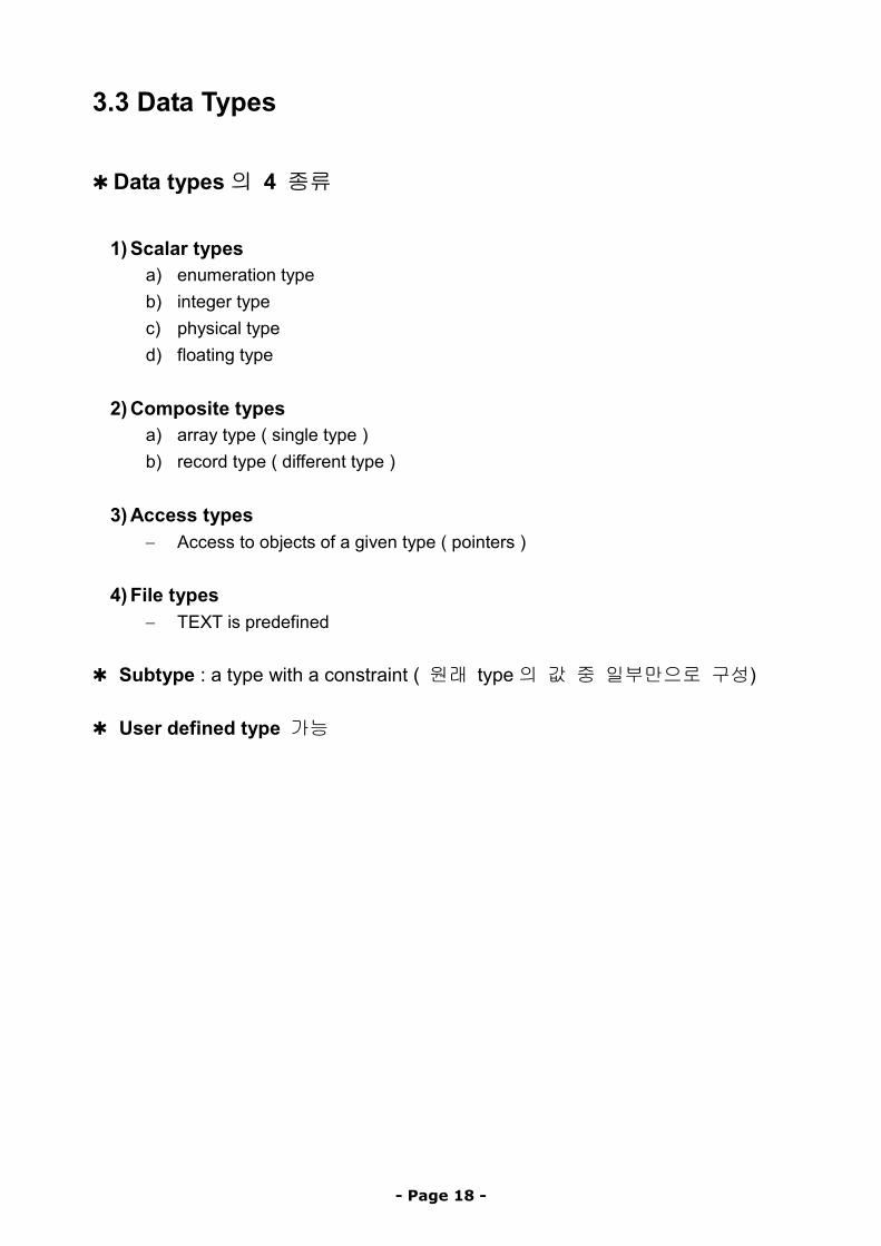
3.3 Data Types
✱ Data types의 4 종류
1) Scalar types
a) enumeration type b) integer type c) physical type d) floating type
2) Composite types
a) array type ( single type ) b) record type ( different type )
3) Access types
− Access to objects of a given type ( pointers )
4) File types − TEXT is predefined
✱ Subtype : a type with a constraint ( 원래 type의 값 중 일부만으로 구성) ✱ User defined type 가능
- Page 18 -
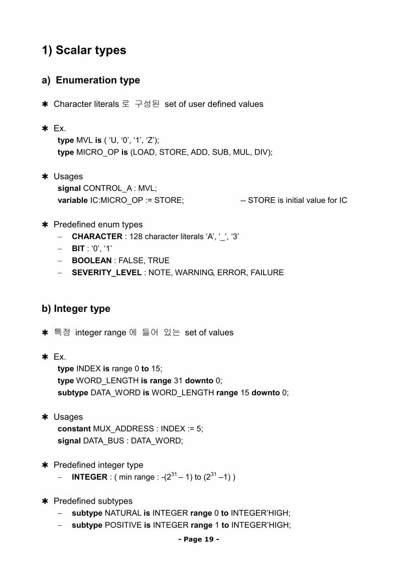
1) Scalar types
a) Enumeration type ✱ Character literals로 구성된 set of user defined values ✱ Ex.
type MVL is ( ‘U, ‘0’, ‘1’, ‘Z’); type MICRO_OP is (LOAD, STORE, ADD, SUB, MUL, DIV);
✱ Usages signal CONTROL_A : MVL; variable IC:MICRO_OP := STORE; -- STORE is initial value for IC
✱ Predefined enum types − CHARACTER : 128 character literals ‘A’, ‘_’, ‘3’ − BIT : ‘0’, ‘1’ − BOOLEAN : FALSE, TRUE − SEVERITY_LEVEL : NOTE, WARNING, ERROR, FAILURE
b) Integer type ✱ 특정 integer range에 들어 있는 set of values ✱ Ex.
type INDEX is range 0 to 15; type WORD_LENGTH is range 31 downto 0; subtype DATA_WORD is WORD_LENGTH range 15 downto 0;
✱ Usages constant MUX_ADDRESS : INDEX := 5; signal DATA_BUS : DATA_WORD;
✱ Predefined integer type − INTEGER : ( min range : -(231 – 1) to (231 –1) )
✱ Predefined subtypes
− subtype NATURAL is INTEGER range 0 to INTEGER’HIGH; − subtype POSITIVE is INTEGER range 1 to INTEGER’HIGH;
- Page 19 -
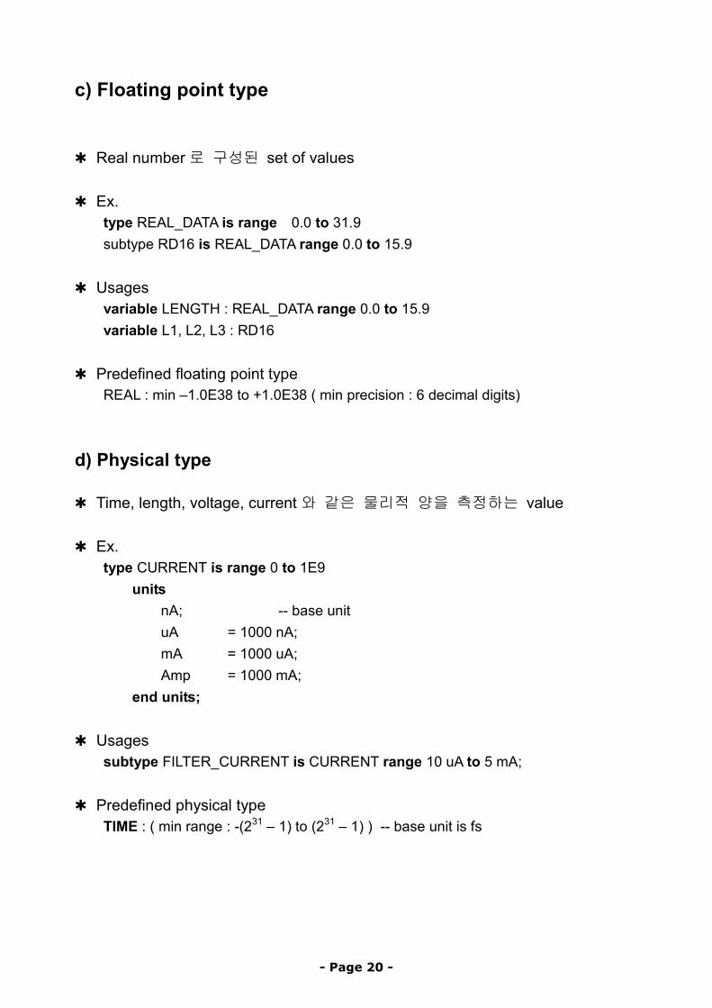
c) Floating point type
✱ Real number로 구성된 set of values ✱ Ex.
type REAL_DATA is range 0.0 to 31.9 subtype RD16 is REAL_DATA range 0.0 to 15.9
✱ Usages variable LENGTH : REAL_DATA range 0.0 to 15.9 variable L1, L2, L3 : RD16
✱ Predefined floating point type REAL : min –1.0E38 to +1.0E38 ( min precision : 6 decimal digits)
d) Physical type ✱ Time, length, voltage, current와 같은 물리적 양을 측정하는 value ✱ Ex.
type CURRENT is range 0 to 1E9 units
nA; -- base unit uA = 1000 nA; mA = 1000 uA; Amp = 1000 mA;
end units;
✱ Usages subtype FILTER_CURRENT is CURRENT range 10 uA to 5 mA;
✱ Predefined physical type TIME : ( min range : -(231 – 1) to (231 – 1) ) -- base unit is fs
- Page 20 -
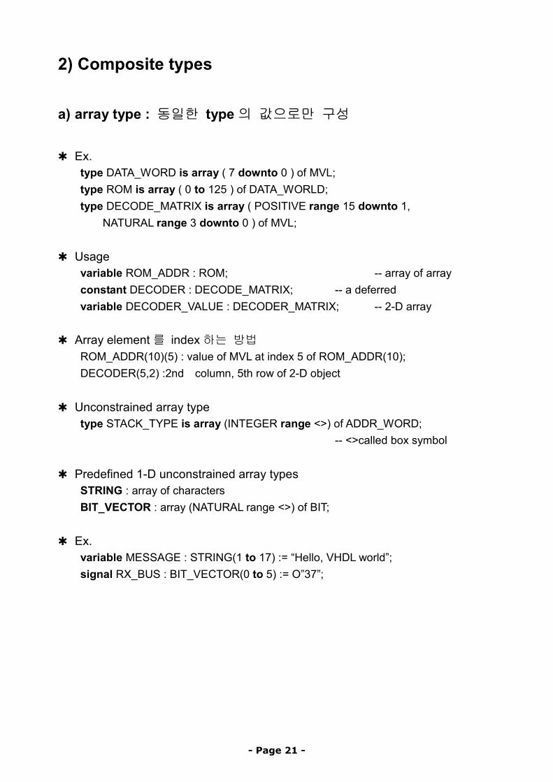
2) Composite types
a) array type : 동일한 type의 값으로만 구성
✱ Ex.
type DATA_WORD is array ( 7 downto 0 ) of MVL; type ROM is array ( 0 to 125 ) of DATA_WORLD; type DECODE_MATRIX is array ( POSITIVE range 15 downto 1,
NATURAL range 3 downto 0 ) of MVL;
✱ Usage variable ROM_ADDR : ROM; -- array of array constant DECODER : DECODE_MATRIX; -- a deferred variable DECODER_VALUE : DECODER_MATRIX; -- 2-D array
✱ Array element를 index하는 방법 ROM_ADDR(10)(5) : value of MVL at index 5 of ROM_ADDR(10); DECODER(5,2) :2nd column, 5th row of 2-D object
✱ Unconstrained array type type STACK_TYPE is array (INTEGER range <>) of ADDR_WORD;
-- <>called box symbol
✱ Predefined 1-D unconstrained array types STRING : array of characters BIT_VECTOR : array (NATURAL range <>) of BIT;
✱ Ex. variable MESSAGE : STRING(1 to 17) := “Hello, VHDL world”; signal RX_BUS : BIT_VECTOR(0 to 5) := O”37”;
- Page 21 -
b) record type : 서로 다른 type으로 구성도 가능
✱ same as “struct” in C, or “record” in PASCAL ✱ Ex.
type PINTYPE is range 0 to 10; type MODULE is
record SIZE : INTEGER range 20 to 200; CRITICAL_DLY : TIME; NO_INPUTS : PIN_TYPE; NO_OUTPUTS : PIN_TYPE;
end record; ✱ Ex. for value assign
variable NAND_COMP : MODULE; NAND_COMP := (50, 20 ns, 3, 2); NAND_COMP.NO_INPUTS := 2;
3) Access type
✱ C에서 “pointer”와 비슷함 ✱ Ex.
type PTR is access MODULE; type FIFO_PTR is access FIFO;
✱ Usages variable MOD1PTR, MOD2PTR : PTR;
✱ Allocator new를 상용해서 dynamically 생성됨 MOD1PTR := new MODULE(25, 10 ns, 4, 9);
✱ Procedure DEALLOCATE DEALLOCATE (MOD1PTR);
✱ Default : null
- Page 22 -

4) File type
✱ Represent files ( file type declaration & file declaration needed ). ✱ Ex. of file type declaration
type VECTORS is file of BIT_VECTOR; type NAMES is file of STRING;
✱ Ex. of file declaration
type file-name : file_type_name is mode string_expression file VEC_FILE : VECCTORS is in “/usr/home/usr/mod/div.vec”; file OUTFILE : NAMES is out “stdout”;
✱ Procedure READ, WRITE, ENDFILE 사용 ✱ Predefined file type (in TEXTIO package)
TEXT : variable length ASCII strings으로 구성 LINE : Access type to point to such strings
- Page 23 -
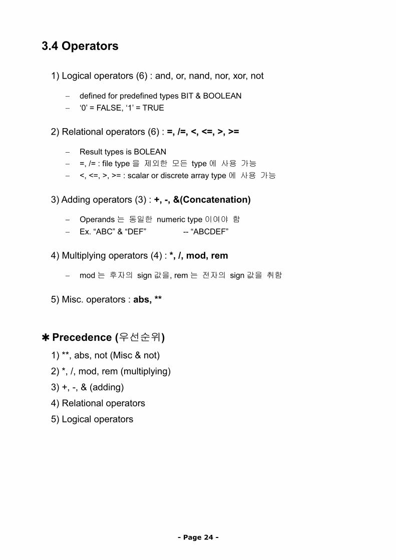
3.4 Operators
1) Logical operators (6) : and, or, nand, nor, xor, not
− defined for predefined types BIT & BOOLEAN − ‘0’ = FALSE, ‘1’ = TRUE
2) Relational operators (6) : =, /=, <, <=, >, >=
− Result types is BOLEAN − =, /= : file type을 제외한 모든 type에 사용 가능 − <, <=, >, >= : scalar or discrete array type에 사용 가능
3) Adding operators (3) : +, -, &(Concatenation)
− Operands는 동일한 numeric type이여야 함 − Ex. “ABC” & “DEF” -- “ABCDEF”
4) Multiplying operators (4) : *, /, mod, rem
− mod는 후자의 sign값을, rem는 전자의 sign값을 취함
5) Misc. operators : abs, **
✱ Precedence (우선순위) 1) **, abs, not (Misc & not)
2) *, /, mod, rem (multiplying)
3) +, -, & (adding)
4) Relational operators
5) Logical operators
- Page 24 -
4. Behavioral Modeling
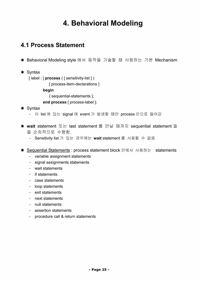
4.1 Process Statement
✱ Behavioral Modeling style에서 동작을 기술할 때 사용하는 기본 Mechanism ✱ Syntax
[ label : ] process ( [ sensitivity-list ] ) [ process-item-declarations ] begin { sequential-statements }; end process [ process-label ];
✱ Syntax − 이 list에 있는 signal에 event가 발생할 때만 process안으로 들어감
✱ wait statement 또는 last statement 를 만날 때까지 sequential statement 들을 순차적으로 수행함. − Sensitivity list가 있는 경우에는 wait statement를 사용할 수 없음
✱ Sequential Statements : process statement block안에서 사용하는 statements
− variable assignment statements − signal assignments statements − wait statements − if statements − case statements − loop statements − exit statements − next statements − null statements − assertion statements − procedure call & return statements
- Page 25 -
4.2 Variable Assignment Statement
✱ Variable – object := expression ✱ 계산된 값이 즉시 variable에 assign됨
− Variable은 해당 process에서만 사용되는 local static variable임 ✱ Ex
process ( A ) variable EVENTS_ON_A : INTEGER := 0;
begin EVENTS_ON_A := EVENTS_ON_A + a;
end process;
4.3 Signal Assignment Statement
✱ Signal-object <= expression [ after delay_value ]; ✱ Expression 이 현재의 simulation 시간에서 evaluation 되고, 계산된 값은
specified delay( after clause ) or delta delay 후에 signal에 assign됨 (Section 4.12의 delay models 참조)
✱ Process안에서는 sequential statement로, 밖에서는 concurrent st.로 사용됨 ✱ Ex.
COUNTER <= COUNTER + “0010”; -- assign after a delta delay PAR <= PAR xor DIN after 12 ns;
✱ 하나의 signal에 여러 개의 값을 assign하는 것이 가능
Phase1 <= ‘0’, ‘1’ after 8 ns, ‘0’ after 13 ns, ‘1’ after 50 ns;
- Page 26 -
4.4 Wait Statement
✱ 3가지 기본 forms 1) wait on sensitivity-list 2) wait until boolean-expression 3) wait for time-expression
또는 위의 조합 (wait on sensitivity-list until boolean-expression for time-expression
✱ Ex. wait on A,B,C; wait until (A=B); wait for 10 ns; wait until (SUM > 100) for 50 ms;
✱ 만약 process가 sensitivity list를 갖고 있지 않다면, wait statement를 적어도 하나는 포함하고 있어야 함(아니면 무한히 수행됨) − 그러나 sensitivity list와 wait statement를 한 process안에 동시에 못 가짐
✱ Sensitivity list : Last statement로 “wait on sensitivity-list” 를 갖고 있는 것과 동일한 효과임
- Page 27 -
4.5 IF Statement
✱ Syntax if boolean-expression then
sequential-statements [ elsif boolean-expression then
sequential-statements [ else
sequential-statements ] end if;
✱ Ex. 1
if SUM <= 100 then -- <= as an operator SUM := SUM + 10;
end if;
✱ Ex. 2 if CTRL = ‘1’ then
if CTRL2 = ‘0’ then -- nesting of if statement MUX_OUT <= “0010”;
else MUX_OUT <= “0001”;
end if; else
if CTRL2 = ‘0’ then MUX_OUT <= “1000”;
else MUX_OUT <= “0100”;
end if; end if;
- Page 28 -
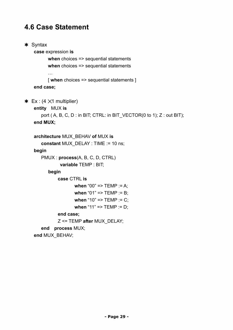
4.6 Case Statement
✱ Syntax case expression is
when choices => sequential statements when choices => sequential statements … [ when choices => sequential statements ]
end case;
✱ Ex : (4 ✕ 1 multiplier) entity MUX is port ( A, B, C, D : in BIT; CTRL: in BIT_VECTOR(0 to 1); Z : out BIT); end MUX; architecture MUX_BEHAV of MUX is constant MUX_DELAY : TIME := 10 ns; begin PMUX : process(A, B, C, D, CTRL) variable TEMP : BIT; begin case CTRL is when “00” => TEMP := A;
when “01” => TEMP := B; when “10” => TEMP := C; when “11” => TEMP := D; end case; Z <= TEMP after MUX_DELAY; end process MUX; end MUX_BEHAV;
- Page 29 -
4.7 Loop Statement
✱ Syntax [ loop-label : ] iteration-scheme loop sequential-statements
end loop [loop-label]; ✱ Iteration schemes의 3가지 형태
1) for identifier in range 2) while boolean-expression 3) no iteration scheme is specified
✱ Ex of for loop
FACTORIAL := 1; for NUMBER in 2 to N loop
FACTORIAL := FACTORIAL* NUMBER; end loop;
✱ Ex of while loop
J := 0; SUM := 10; while J < 20 loop
SUM := SUM *2; J := J + 3;
end loop;
✱ Ex of no iteration scheme used SUM := 1; J := 0; L2 : loop
J := J + 21; SUM := SUM*10; exit when SUM >100;
end loop L2;
- Page 30 -

4.8 Exit Statement
✱ Loop내에서 loop를 빠져 나올 때 사용 ✱ Syntax
exit [ loop-label] [ when condition ];
✱ Ex : (Section 4.7 참조) ✱ Loop-label 이 지정되어 있으면 해당 loop 를, 없으면 가장 안쪽의 loop 를 빠져 나옴
4.9 Next Statement
✱ Loop 내에서 현재 iteration 의 남아있는 부분을 건너뛰고, 새로운 iteration을 시작함
✱ Syntax
next [ loop-label ] [ when condition ];
✱ Ex. L4 : for k in 10 downto 1 loop
L5 : loop -- statements next L4 when WR_DONE = ‘1’; -- statements
end loop L5; -- statements
end loop L4;
- Page 31 -
4.10 Null Statement
✱ Syntax null;
✱ 아무런 action없이 다음으로 넘어감 ✱ if or case statement 안에서 사용
4.11 Assertion Statement
✱ Entity의 어떤 constraints을 check하는데 사용 − Assertion condition이 false일 때 active되어 error를 report함 − Signal 값이 range를 벗어나든지, setup time violation시 error report 발생
✱ Syntax
assert boolean- expression [ report string-expression ] [ severity severity-level-expression ];
✱ Severity-level expression : predefined enum type SEVERITY_LEVEL ✱ Ex. 1
assert (DATA <= 255) report “Data out of range”;
✱ Ex. 2 assert (CLK = ‘0’) or (CLK = ‘1’); -- default message “Assertion violation” is printed -- default severity level is ERROR
- Page 32 -
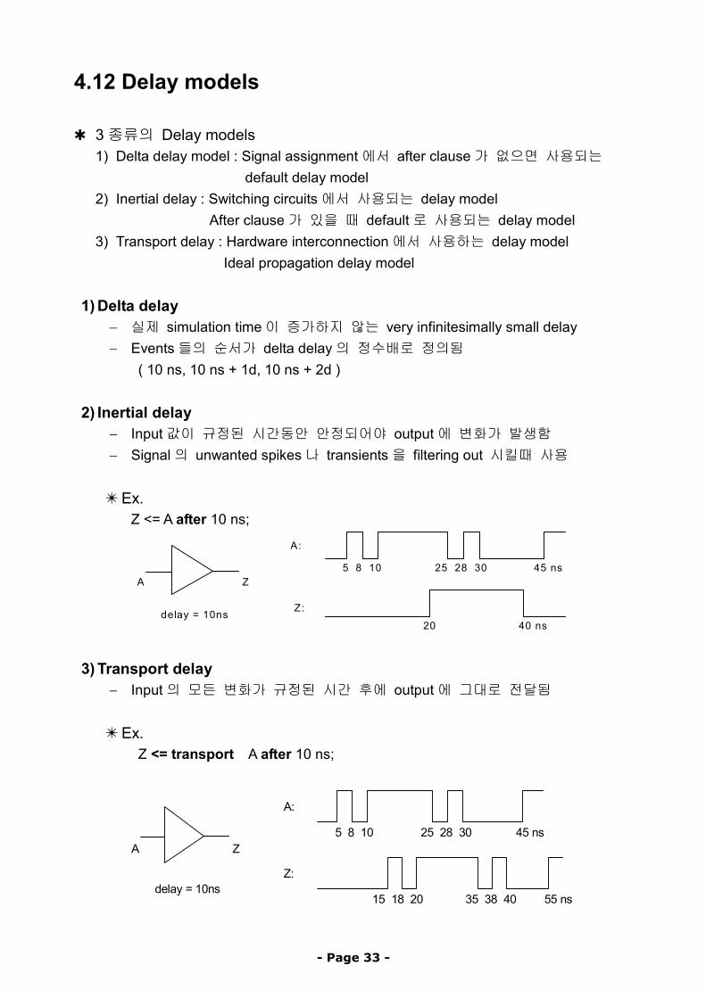
4.12 Delay models
✱ 3종류의 Delay models 1) Delta delay model : Signal assignment에서 after clause가 없으면 사용되는
default delay model 2) Inertial delay : Switching circuits에서 사용되는 delay model
After clause가 있을 때 default로 사용되는 delay model 3) Transport delay : Hardware interconnection에서 사용하는 delay model Ideal propagation delay model
1) Delta delay − 실제 simulation time이 증가하지 않는 very infinitesimally small delay − Events들의 순서가 delta delay의 정수배로 정의됨
( 10 ns, 10 ns + 1d, 10 ns + 2d )
2) Inertial delay − Input값이 규정된 시간동안 안정되어야 output에 변화가 발생함 − Signal의 unwanted spikes나 transients을 filtering out 시킬때 사용
✴ Ex. Z <= A after 10 ns;
A Z
delay = 10ns
A:
Z:
5 8 10 25 28 30 45 ns
20 40 ns
3) Transport delay − Input의 모든 변화가 규정된 시간 후에 output에 그대로 전달됨
✴ Ex. Z <= transport A after 10 ns;
A Z
A:
5 8 10 25 28 30 45 ns
Z:
15 18 20 35 38 40 55 ns delay = 10ns
- Page 33 -
4.13 More signal assignment in a process
1) Signal Driver
✱ Process안에 있는 signal assignment는 해당 signal에 대해 driver를 생성함 − Signal driver는 해당 signal의 현재 값과 미래 값을 sequence of transactions으로 갖고 있음. Wait statement가 수행되어야만 assign된 값을 갖게 됨
✱ Ex
signal A, Z : INTEGER process (A) -- if an event on signal A occurred at time T,
variable V1, V2 : INTEGER begin
V1 := A – V2; -- V1 gets new value at time T Z <= - V1; -- Z is scheduled to get a new value at wait st V2 := Z + V1 * 2; -- V2는 signal Z의 예전 값으로 계산됨
end process;
- Page 34 -
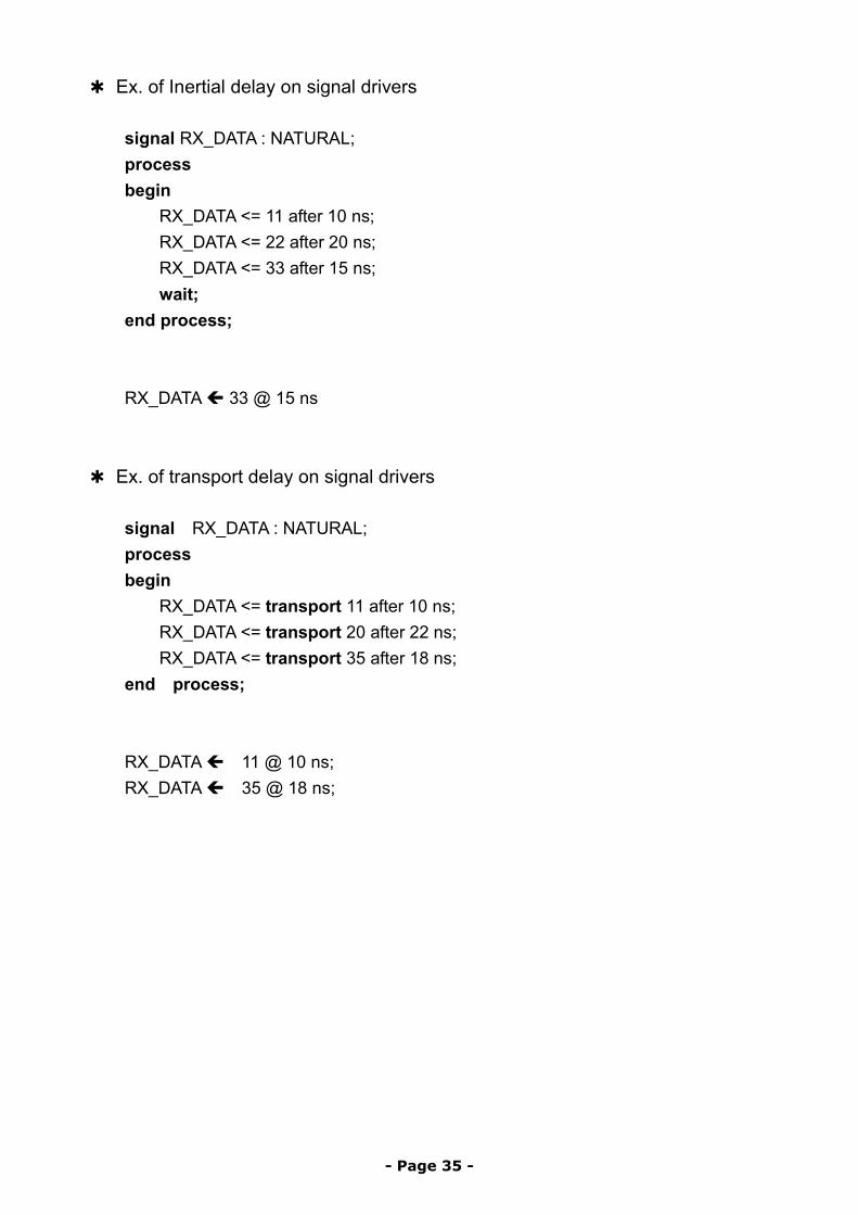
✱ Ex. of Inertial delay on signal drivers
signal RX_DATA : NATURAL; process begin
RX_DATA <= 11 after 10 ns; RX_DATA <= 22 after 20 ns; RX_DATA <= 33 after 15 ns; wait;
end process; RX_DATA 33 @ 15 ns
✱ Ex. of transport delay on signal drivers
signal RX_DATA : NATURAL; process begin
RX_DATA <= transport 11 after 10 ns; RX_DATA <= transport 20 after 22 ns; RX_DATA <= transport 35 after 18 ns;
end process; RX_DATA 11 @ 10 ns; RX_DATA 35 @ 18 ns;
- Page 35 -
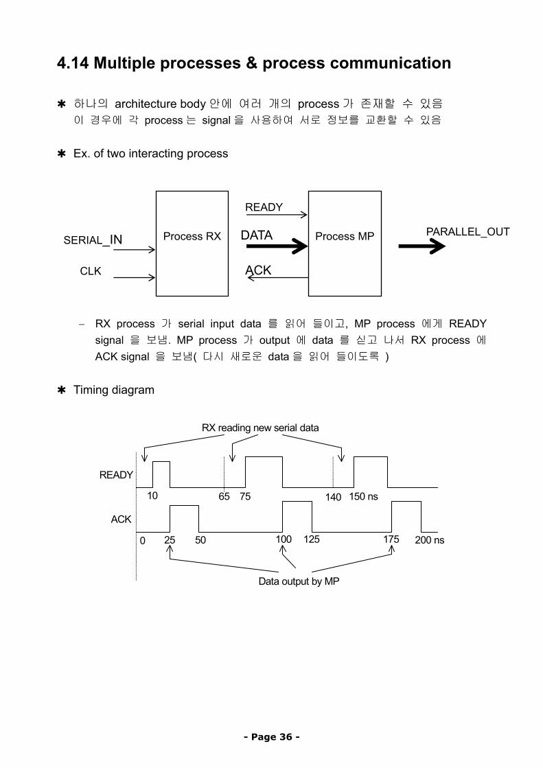
4.14 Multiple processes & process communication
✱ 하나의 architecture body안에 여러 개의 process가 존재할 수 있음 이 경우에 각 process는 signal을 사용하여 서로 정보를 교환할 수 있음
✱ Ex. of two interacting process
ACK
PARALLEL_OUTDATA
READY
SERIAL_IN
Process MP
Process RX
CLK
− RX process 가 serial input data 를 읽어 들이고, MP process 에게 READY
signal 을 보냄. MP process 가 output 에 data 를 싣고 나서 RX process 에 ACK signal 을 보냄( 다시 새로운 data을 읽어 들이도록 )
✱ Timing diagram
Data output by MP
0 25 50 100 125 175 200 ns
10 65 75 140 150 ns
RX reading new serial data
READY
ACK
- Page 36 -
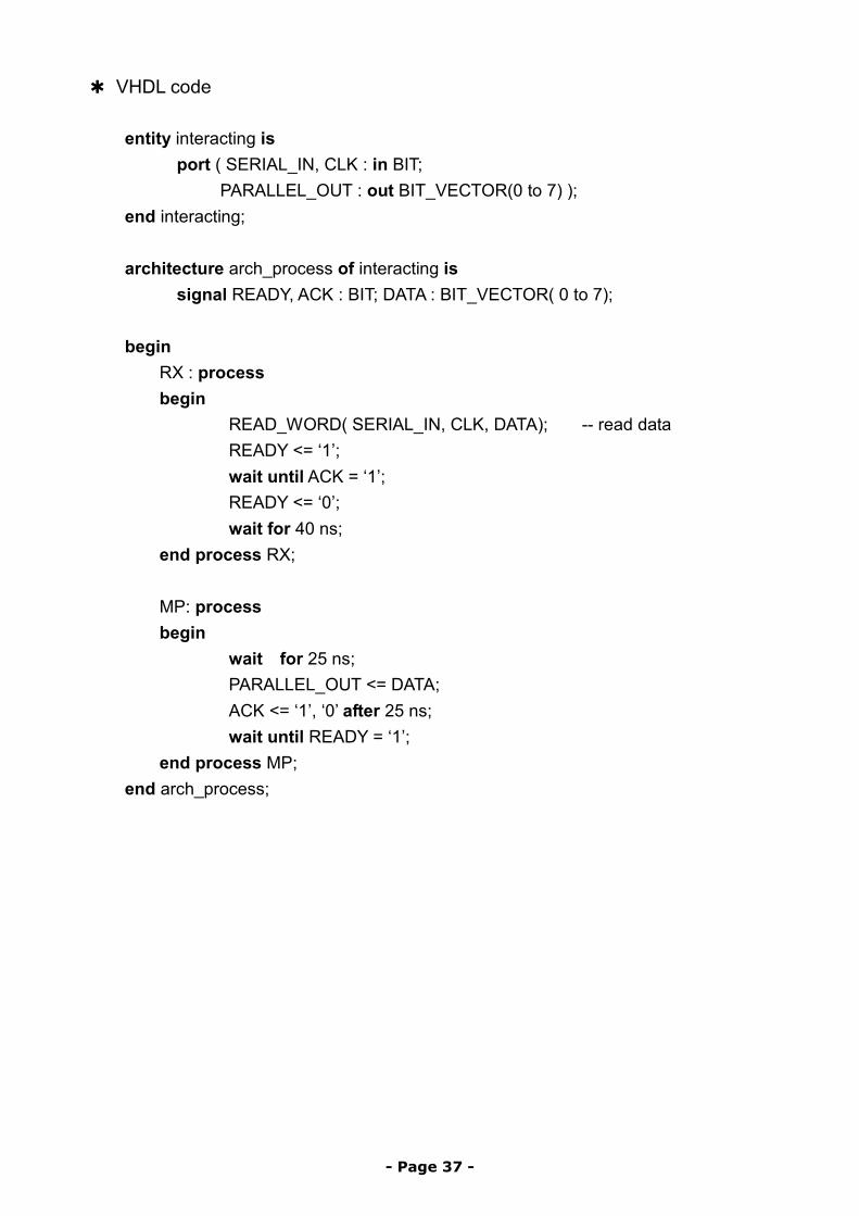
✱ VHDL code
entity interacting is port ( SERIAL_IN, CLK : in BIT;
PARALLEL_OUT : out BIT_VECTOR(0 to 7) ); end interacting; architecture arch_process of interacting is
signal READY, ACK : BIT; DATA : BIT_VECTOR( 0 to 7);
begin RX : process begin
READ_WORD( SERIAL_IN, CLK, DATA); -- read data READY <= ‘1’; wait until ACK = ‘1’; READY <= ‘0’; wait for 40 ns;
end process RX; MP: process begin
wait for 25 ns; PARALLEL_OUT <= DATA; ACK <= ‘1’, ‘0’ after 25 ns; wait until READY = ‘1’;
end process MP; end arch_process;
- Page 37 -
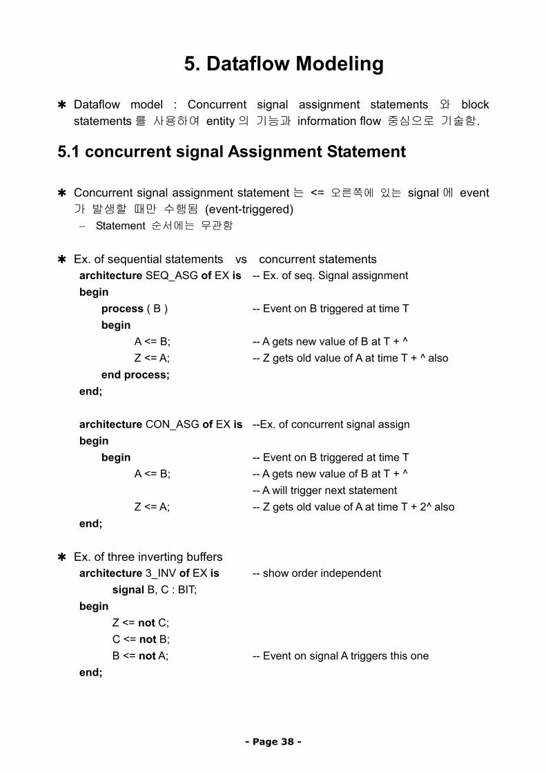
5. Dataflow Modeling
✱ Dataflow model : Concurrent signal assignment statements 와 block statements를 사용하여 entity의 기능과 information flow 중심으로 기술함.
5.1 concurrent signal Assignment Statement
✱ Concurrent signal assignment statement는 <= 오른쪽에 있는 signal에 event 가 발생할 때만 수행됨 (event-triggered) − Statement 순서에는 무관함
✱ Ex. of sequential statements vs concurrent statements architecture SEQ_ASG of EX is -- Ex. of seq. Signal assignment begin
process ( B ) -- Event on B triggered at time T begin
A <= B; -- A gets new value of B at T + ^ Z <= A; -- Z gets old value of A at time T + ^ also
end process; end; architecture CON_ASG of EX is --Ex. of concurrent signal assign begin
begin -- Event on B triggered at time T A <= B; -- A gets new value of B at T + ^ -- A will trigger next statement Z <= A; -- Z gets old value of A at time T + 2^ also
end;
✱ Ex. of three inverting buffers architecture 3_INV of EX is -- show order independent
signal B, C : BIT; begin
Z <= not C; C <= not B; B <= not A; -- Event on signal A triggers this one
end;
- Page 38 -
5.2 Conditional Signal Assignment Statement
✱ 주어진 condition에 따라 target-signal에 다른 값이 assign됨 (Behavioral에서 if statement와 비슷) ✱ Syntax
target-signal <= {waveform-elements when condition else} waveform-elements;
✱
architecture DFF of D_FF is begin
q <= ‘0’ when rst = ‘0’ else d when clk = ‘1’ and (not clk’stable) else -- rising edge q;
end DFF;
- Page 39 -
5.3 Selected Signal Assignment Statement
✱ Select expression에 따라 target-signal에 다른 값이 assign됨 (Behavioral에서 case statement와 비슷)
✱ Syntax with expression select target-signal <= waveform-elements when choices
{waveform-elements when choices};
✱ Ex type OP is (ADD, SUB, MUL, DIV); signal OP_CODE : OP; with OP_CODE select
Z <= A + B after 3 ns when ADD, A – B after 3 ns when SUB, A * B after MUL_DLY when MUL, A / B after DIV_DLY when DIV;
✱ Equivalent process statement
process begin
case OP_CODE is when ADD => Z <= A + B after 3 ns; when SUB => Z <= A – B after 3 ns; when MUL => Z <= A * B after MUL_DLY; when DIV => Z<= A / B after DIV_DLY;
end case; wait on OP_CODE, A, B;
end process;
- Page 40 -
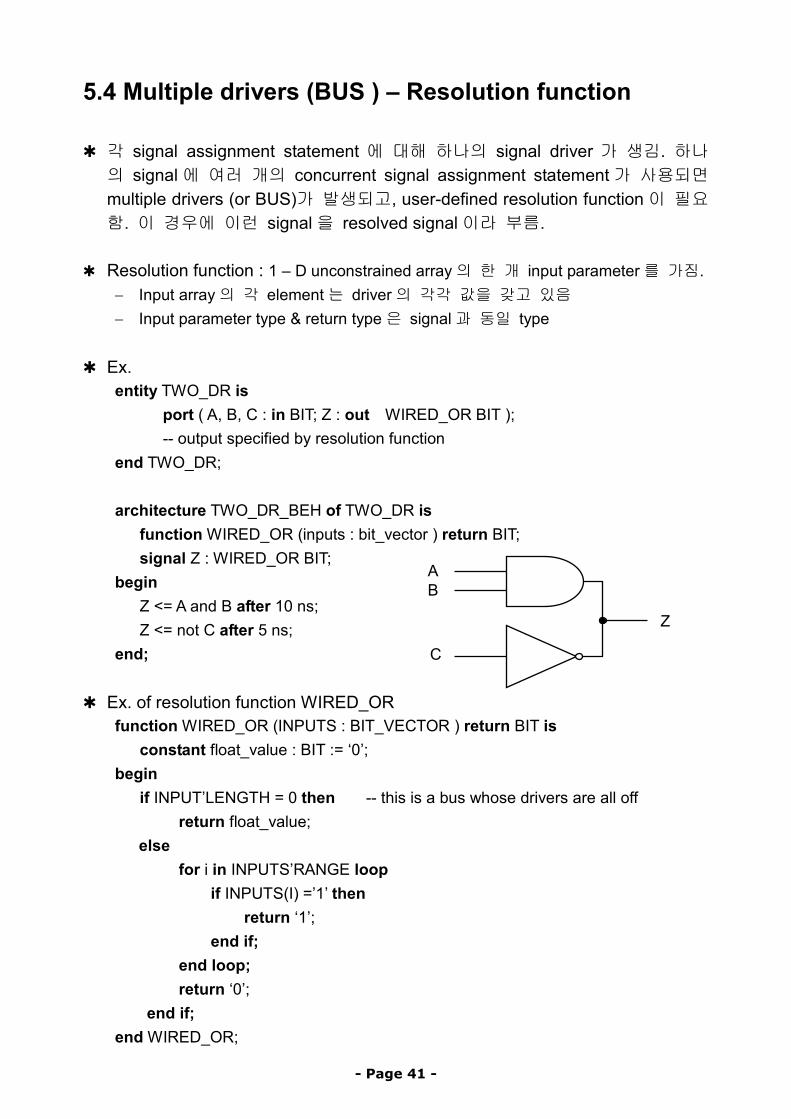
5.4 Multiple drivers (BUS ) – Resolution function
✱ 각 signal assignment statement 에 대해 하나의 signal driver 가 생김. 하나의 signal에 여러 개의 concurrent signal assignment statement가 사용되면 multiple drivers (or BUS)가 발생되고, user-defined resolution function이 필요함. 이 경우에 이런 signal을 resolved signal이라 부름.
✱ Resolution function : 1 – D unconstrained array의 한 개 input parameter를 가짐.
− Input array의 각 element는 driver의 각각 값을 갖고 있음 − Input parameter type & return type은 signal과 동일 type
✱ Ex.
entity TWO_DR is port ( A, B, C : in BIT; Z : out WIRED_OR BIT ); -- output specified by resolution function
end TWO_DR; architecture TWO_DR_BEH of TWO_DR is function WIRED_OR (inputs : bit_vector ) return BIT; signal Z : WIRED_OR BIT;
ABbegin
Z <= A and B after 10 ns; Z Z <= not C after 5 ns;
end; C
✱ Ex. of resolution function WIRED_OR function WIRED_OR (INPUTS : BIT_VECTOR ) return BIT is constant float_value : BIT := ‘0’; begin if INPUT’LENGTH = 0 then -- this is a bus whose drivers are all off
return float_value; else
for i in INPUTS’RANGE loop if INPUTS(I) =’1’ then return ‘1’; end if; end loop; return ‘0’; end if;
end WIRED_OR;
- Page 41 -
6. Structural Modeling ✱ Entity가 .signal에 의해 연결된 H/W component 집합으로 modeling됨
6.1 Component Declaration
✱ Subcomponent로 사용할 entity의 이름과 interface를 선언함 − Architecture body나 package의 서언부(declarative part)에 기술함
✱ Syntax component component-name
port (list-of-interface-ports); [ generic (generic-association); ]
end component;
✱ Ex. component MP
port (CK, RESET, RDN, WRN : in BIT; DATA_BUS : inout INTEGER range 0 to 255; ADDER_BUS : in BIT_VECTOR ( 15 downto 0 ) );
end component;
- Page 42 -
6.2 Component Instantiation
✱ Entity내에서 사용되는 subcomponent를 정의함 − Instance 이름, 실제 사용할 signal 이름 등을 mapping 하게 됨 − Architecture나 package의 본문 속에서 (after begin) 사용함
✱ Syntax
Instantiation-label : component-name port map ( association-list ) [ generic map (association-list) ]; − Instantiation-label은 instance 이름으로 간주됨
✱ Entity 에서 사용하는 actual signal 이름과 component declaration 에서 사용한 local이름을 연결(Association)해 줌
✱ Actual 이름과 local 이름을 associate 해주는 두 가지 방법
1) positional association : component선언문에 나타난 port 순서대로 mapping 2) named association : local1 => actual1, local2 => actual2,…
✱ Ex. -- component declaration component NAND2
port ( A, B : in BIT; Z : out BIT); end component; -- component instantiation with positional association N1 : NAND2 port map ( S1, S2, S3 ); -- component instantiation with named association N2 : NAND2 port map (A => S1, B => S2, Z => S3); -- component instantiation with keyword open (ie. port is not connected) N3 : NAND2 port map ( S1, open, S3 );
- Page 43 -
6.3 Generics
✱ Entity declaration 과 이에 대응하는 architecture body 에서 parameterized 정보를 전달하기 위해서 사용하는 constant object − Interface port의 크기, rise & fall delays등을 parameter로 표현 − 사용 node는 in(2장의 entity declaration 참조) − Generic constant는 component declaration, component instantiation,
configuration specification, configuration declaration에서 local static값으로 지정하여 사용
✱ Ex.1
entity NAND is generic ( N : NATURAL ); port ( A : in BIT_VECTOR ( 1 to N ); Z : out BIT );
end NAND; architecture GEN_EX of GEN_EX is component NAND
generic ( N : NATURAL := 5 ); port ( A : in BIT_VECTOR ( 1 to N ); Z : out BIT );
end component; signal S1, S2, S3, S4 : BIT; SA, SB, : BIT_VECTOR( 1 to 5 );
begin A1 : AND_GATE port map ( SA, S4 ); -- use default value A2 : AND_GATE generic map ( N => 3) port map ( SB, S3 );
end GEN_EX;
✱ Ex. 2 entity NOR2 is
generic ( PT_HL, PT_LH : TIME ); port (A, B : BIT ; Z : out BIT );
end NOR2; architecture NOR2_DELAYS of NOR2 is
signal TEMP : BIT; begin
TEMP <= not ( A or B ); Z <= TEMP after PT_HL when ( TEMP = ‘0’ ) else TEMP after PT_LH;
end NOR2_DELAYS; -- component instantiation of NOR2 N1 : NOR2 generic map ( 5 ns, 3 ns ) port map (A, B, S1);
- Page 44 -

6.4 Configuration specification
✱ Component instantiation시 특정 component를 특정 entity에 결함함. − Configuration의 다른 형태임 ( Section 2.3과 비교 ) − Architecture의 서술부에 위치함 ( 변경 시 불편 )
✱ Syntax for comp-labels : component-name use entity entity-name [ (architecture-name) ] -- binding-indication
[ generic map (generic-association) ] [ port map (port-association) ]
✱ Ex.
architecture arch_DUMMY of DUMMY is component NOR_GATE
generic (RISE_TIME, FALL_TIME : TIME); port (S0, S1 : in BIT; Q : out BIT ); end component;
for N1, N2 : NOR_GATE
use entity WORK.NOR2 (NOR2_DELAYS) generic map (PT_HL => FL_TIME, PT_LH => RS_TIME); port map (S0, S1, Q);
signal WR, RD, RW : BIT; begin
N1 : NOR_GATE generic map (2 ns, 3 ns ) port map (WR, RD, RW); …
end arch_DUMMY;
- Page 45 -
7. Subprogram & Overloading
✱ 두 종류의 subprogram 1) Function : Single value를 계산하기 위해 주로 사용 2) Procedure : Mode parameter out, inout을 사용하여 여러 개의 값을 return할 수 있음. 주로 큰 회로의 partition을 위해 사용
7.1 Function
✱ 주로 resolution function, type conversion, overloading operator를 위해 사용 − Passing parameter는 in mode만 가능하고 (constant, signal만 passing가능),
function안에서 변경이 안됨 − Function body는 package body나 calling block의 서술부에 위치함
✱ Syntax for function body
function ft_name [ (para_list) ] return ret_type is item_declarations
begin sequential_statements -- 단 wait statement는 허용 안됨
end [ ft_name ];
✱ Syntax for function call; ft_name [ (actual_para_list) ]
✱ Ex
function LARGEST ( tatal_no : integer; set : pattern ) return real is variable return_val : real := 0;
begin for K in 1 to total_no loop
if set(k) > return_val then return_val := set (k);
end if; end loop; return return_val;
end LARGEST; -- function call sum := sum + LARGEST (max_coins, collection);
- Page 46 -
7.2 Procedure
✱ 주로 큰 회로의 partitioning을 위해 사용함 − Passing parameter는 in, out, inout이 가능하고, constant, signal, variable 모두를 passing 할 수 있음 (Default : constant for in, variable for out, inout)
✱ Syntax for procedure body
procedure proc_name [(para_list)] is item_declarations
begin sequential_statements -- wait statement도 허용됨
end [proc_name];
✱ Syntax for procedure call procedure-name (actural_para_list);
✱ Ex
type OP_CODE is (ADD, SUB, MUL, DIV, LT, LE, EQ); … procedure ALU (A, B : in integer; OP: in OP_CODE;
Z : out integer; ZCOMP : out BOOLEAN) is begin
case OP is when ADD => Z := A + B; when SUB => Z := A - B; when MUL => Z := A * B; when DIV => Z := A / B; when LT => Z := A < B; when LE => Z := A <= B; when EQ => Z := A = B; when others => null;
end case; end ALU; -- procedure call ALU (D1, D2, ADD, SUM, COMP);
- Page 47 -
7.3 Subprogram Overloading
✱ 두개 이상의 subprograms이 동일한 이름을 가질 수 있음 − 단 parameter의 숫자나 type이 달라야 함
✱ 구별하는 방안
1) Parameter type.에 의한 구별 function COUNT (ORANGES : integer ) return integer; function COUNT (APPLES : BIT ) return integer; … COUNT (20); COUNT(‘1’);
2) Parameter의 개수에 의한 구별
function SMALLEST (A1, A2 : integer ) return integer; function SMALLEST (A1, A2, A3, A4 : integer ) return integer; … SMALLEST (4, 5 ); SMALLEST (20, 35, 1, 52 );
- Page 48 -
7.4 Operator Overloading
✱ Predefined operators는 특정 type의 operand에 대해서만 정의되어 있는데, function body를 사용하여 다른 type에 대해서도 사용할 수 있도록 함. − Overloaded operator : double quotes와 함께 사용함
✱ Ex. function “not” (op1 : in bit4) return bit4 is begin
case op1 is when ‘0’ => return ‘1’; when ‘1’ => return ‘0’; when others => return ‘X’;
end case; end “not”; architecture df of EX is
signal a, b, x, y : BIT4; function “not” (op1 : in BIT4) return BIT4;
begin a <= not b; -- pre-defined not operator; y <= “not” (x); -- overloaded not operator;
end ;
- Page 49 -

8. Advanced Features
8.1 Entity Statement
✱ Entity architecture에 공통으로 미리 check할 내용을 위해 사용( I/F check ) − Entity declaration 안에 위치함 ( section 2.2 참조 ) − Passive statement만 사용해야 하고, signal assignment는 안됨 − 주로, assertion statement, procedure call, process statement를 사용함
✱ Syntax
entity entity_name is [ generic (…) ; ] [ port (…); ] [ entity_common_declarations ] -- common declarations
[ begin entity_statements ] -- common statements
end [ entity_name ];
✱ Ex. 1 -- check for RS FF inputs never high simultaneously entity RS_FF is
port (R, S : in Bit; Q, QBAR : out BIT); constant FF_DLY : TIME := 24 ns; type FF_STATE is (ONE, ZERO, UNKNOWN);
begin assert not (R = ‘1’ and S = ‘1’)
report (“Not valid inputs !”); severity ERROR;
end RS_FF;
✱ Ex. 2 use WORK.MYPACK.CHECK_SETUP; entity DFF is
port (D, CLK : in BIT; Q, QBAR : out BIT); constant SETUP : TIME := 7 ns;
begin CHECK_SETUP (D, CLK, SETUP); -- procedure call
end DFF;
- Page 50 -

8.2 Generate Statement
✱ Concurrent statement를 반복하거나 조건적으로 수행하게 함 − Regular structure (memory, registers, counters)에 주로 사용됨
✱ 두 가지 형태 1) for-generatoin 형태 사용 : statement가 정해진 횟수 만큼 반복 2) if-generation 형태 사용 : statement가 condition에 따라 수행됨
1) Syntax for for-generation scheme
generate-label : for generation-id in range generate concurrent-statements
end generate [ generate-label ];
✱ Ex. entity FULL_ADD4 is
port (A, B : in BIT_VECTOR ( 3 downto 0 ); CIN : in BIT ; SUM : out BIT_VECTOR ( 3 downto 0 ); COUT : out BIT );
end FULL_ADD4; architecture EX_GEN of FULL_ADD4 is
component FULL_ADD port (A, B, C : in BIT; COUT, SUM : out BIT);
end component; signal CAR : BIT_VECTOR( 4 downto 0 );
begin CAR(0) <= CIN; GK1 : for K in 3 downto 0 generate
FA : FULL_ADD port map (CAR(K), A(K), B(K), CAR(K+1), SUM (K)); end generate GK1; COUT <= CAR(4);
end EX_GEN;
FA3 FA2 FA1 FA0
A(3) B(3) A(2) B(2) A(1) B(1) A(0) B(0)
CIN
COUTSUM(3)
CAR(3)
SUM(2) SUM(1) SUM(0)
CAR(2) CAR(1)
- Page 51 -
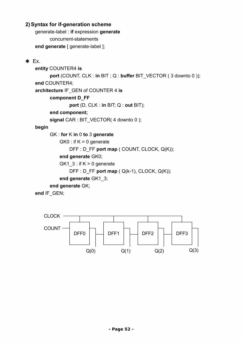
2) Syntax for if-generation scheme generate-label : if expression generate
concurrent-statements end generate [ generate-label ];
✱ Ex.
entity COUNTER4 is port (COUNT, CLK : in BIT ; Q : buffer BIT_VECTOR ( 3 downto 0 ));
end COUNTER4; architecture IF_GEN of COUNTER 4 is
component D_FF port (D, CLK : in BIT; Q : out BIT);
end component; signal CAR : BIT_VECTOR( 4 downto 0 );
begin GK : for K in 0 to 3 generate
GK0 : if K = 0 generate DFF : D_FF port map ( COUNT, CLOCK, Q(K));
end generate GK0; GK1_3 : if K > 0 generate
DFF : D_FF port map ( Q(k-1), CLOCK, Q(K)); end generate GK1_3;
end generate GK; end IF_GEN;
DFF0 DFF1 DFF2 DFF3
CLOCK
COUNT
Q(0) Q(1) Q(2) Q(3)
- Page 52 -
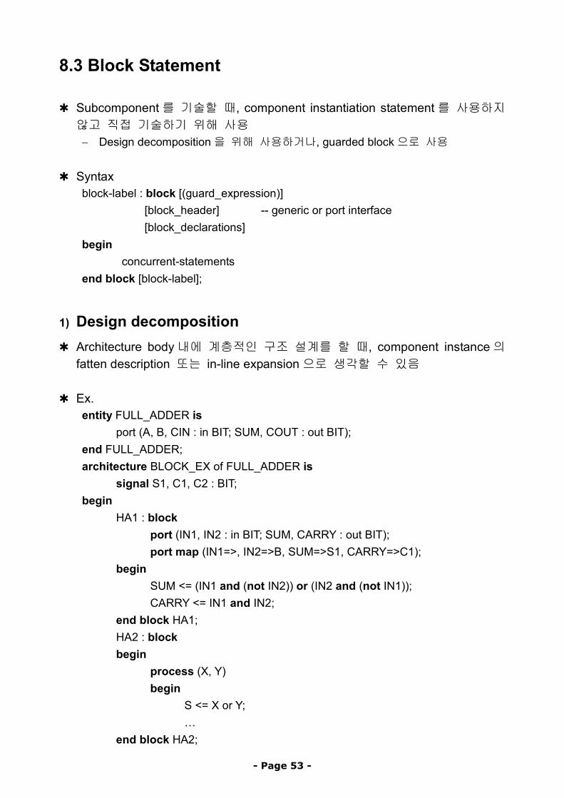
8.3 Block Statement
✱ Subcomponent를 기술할 때, component instantiation statement를 사용하지 않고 직접 기술하기 위해 사용 − Design decomposition을 위해 사용하거나, guarded block으로 사용
✱ Syntax
block-label : block [(guard_expression)] [block_header] -- generic or port interface [block_declarations]
begin concurrent-statements
end block [block-label];
1) Design decomposition
✱ Architecture body내에 계층적인 구조 설계를 할 때, component instance의 fatten description 또는 in-line expansion으로 생각할 수 있음
✱ Ex.
entity FULL_ADDER is port (A, B, CIN : in BIT; SUM, COUT : out BIT);
end FULL_ADDER; architecture BLOCK_EX of FULL_ADDER is
signal S1, C1, C2 : BIT; begin
HA1 : block port (IN1, IN2 : in BIT; SUM, CARRY : out BIT); port map (IN1=>, IN2=>B, SUM=>S1, CARRY=>C1);
begin SUM <= (IN1 and (not IN2)) or (IN2 and (not IN1)); CARRY <= IN1 and IN2;
end block HA1; HA2 : block begin
process (X, Y) begin
S <= X or Y; …
end block HA2;
- Page 53 -
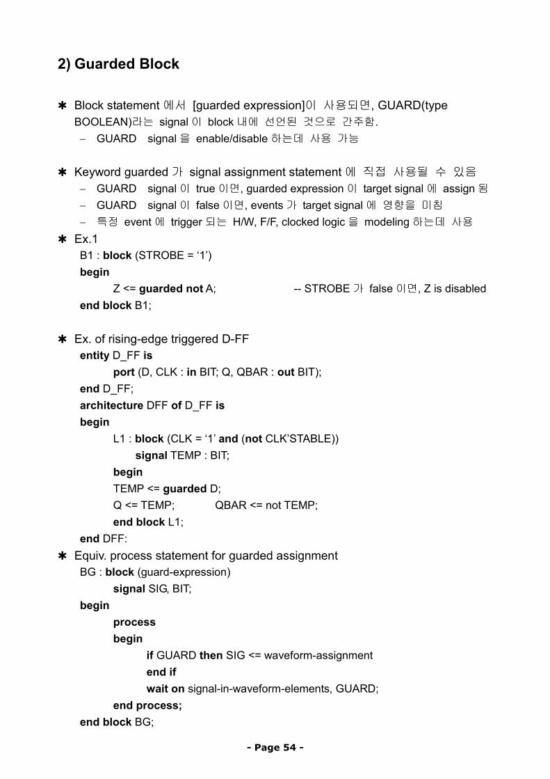
2) Guarded Block ✱ Block statement에서 [guarded expression]이 사용되면, GUARD(type BOOLEAN)라는 signal이 block내에 선언된 것으로 간주함.
− GUARD signal을 enable/disable하는데 사용 가능
✱ Keyword guarded가 signal assignment statement에 직접 사용될 수 있음 − GUARD signal이 true이면, guarded expression이 target signal에 assign됨 − GUARD signal이 false이면, events가 target signal에 영향을 미침 − 특정 event에 trigger되는 H/W, F/F, clocked logic을 modeling하는데 사용
✱ Ex.1 B1 : block (STROBE = ‘1’) begin
Z <= guarded not A; -- STROBE가 false이면, Z is disabled end block B1;
✱ Ex. of rising-edge triggered D-FF entity D_FF is
port (D, CLK : in BIT; Q, QBAR : out BIT); end D_FF; architecture DFF of D_FF is begin
L1 : block (CLK = ‘1’ and (not CLK’STABLE)) signal TEMP : BIT;
begin TEMP <= guarded D; Q <= TEMP; QBAR <= not TEMP; end block L1;
end DFF: ✱ Equiv. process statement for guarded assignment
BG : block (guard-expression) signal SIG, BIT;
begin process begin
if GUARD then SIG <= waveform-assignment end if wait on signal-in-waveform-elements, GUARD;
end process; end block BG;
- Page 54 -
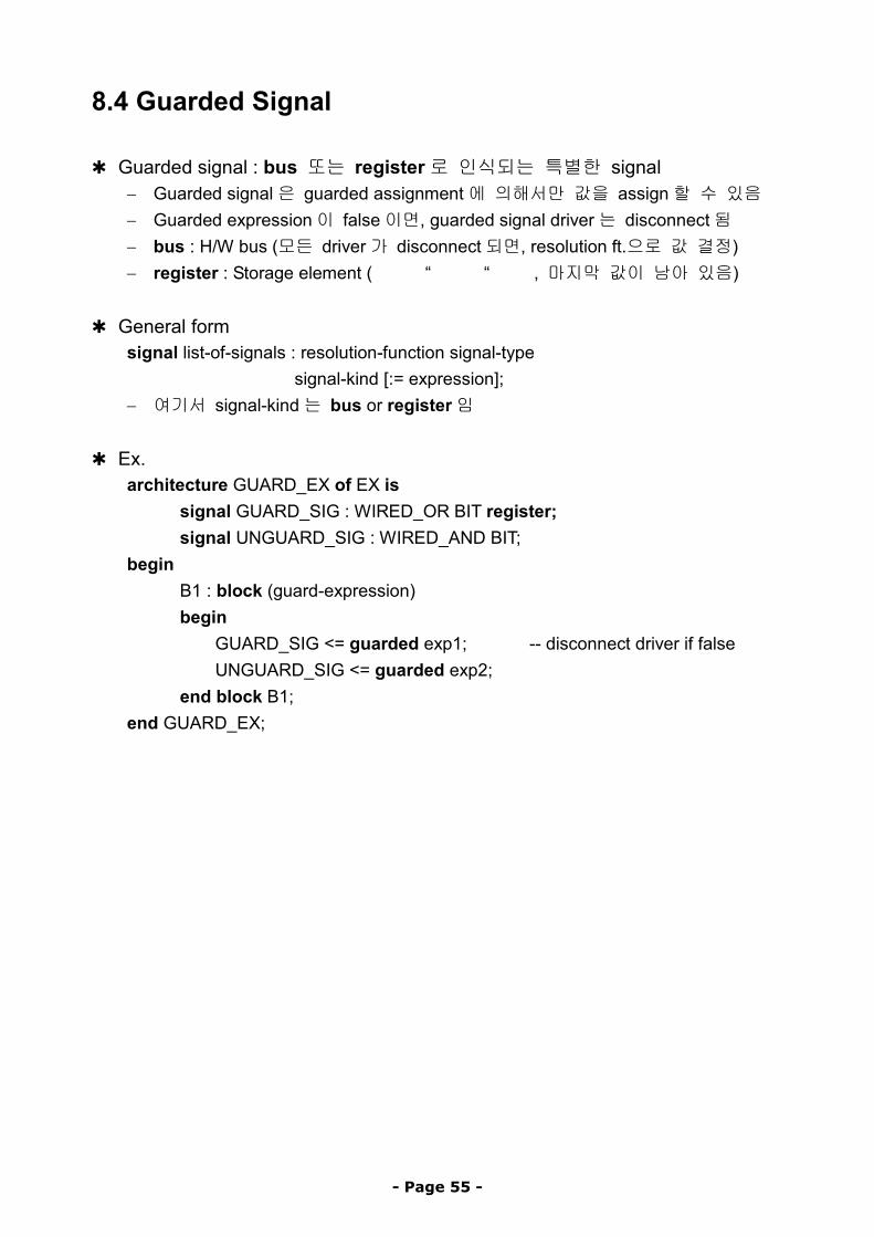
8.4 Guarded Signal
✱ Guarded signal : bus 또는 register로 인식되는 특별한 signal − Guarded signal은 guarded assignment에 의해서만 값을 assign할 수 있음 − Guarded expression이 false이면, guarded signal driver는 disconnect됨 − bus : H/W bus (모든 driver가 disconnect되면, resolution ft.으로 값 결정) − register : Storage element ( “ “ , 마지막 값이 남아 있음)
✱ General form signal list-of-signals : resolution-function signal-type
signal-kind [:= expression]; − 여기서 signal-kind는 bus or register임
✱ Ex.
architecture GUARD_EX of EX is signal GUARD_SIG : WIRED_OR BIT register; signal UNGUARD_SIG : WIRED_AND BIT;
begin B1 : block (guard-expression) begin
GUARD_SIG <= guarded exp1; -- disconnect driver if false UNGUARD_SIG <= guarded exp2;
end block B1; end GUARD_EX;
- Page 55 -
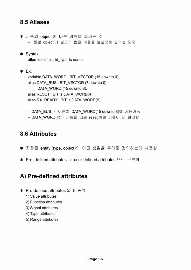
8.5 Aliases
✱ 기존의 object에 다른 이름을 붙이는 것 − 동일 object에 별도의 짧은 이름을 붙임으로 편의성 도모
✱ Syntax alias identifier : id_type is name;
✱ Ex.
variable DATA_WORD : BIT_VECTOR (15 downto 0); alias DATA_BUS : BIT_VECTOR (7 downto 0);
DATA_WORD (15 downto 8); alias RESET : BIT is DATA_WORD(4); alias RX_READY : BIT is DATA_WORD(5); -- DATA_BUS란 이름이 DATA_WORD(15 downto 8)에 사용가능 -- DATA_WORD(4)가 사용될 때는 reset이란 이름이 더 편리함
8.6 Attributes
✱ 지정된 entity (type, object)의 어떤 성질을 추가로 정의하는데 사용함 ✱ Pre_defined attributes과 user-defined attributes으로 구분함
A) Pre-defined attributes
✱ Pre-defined attributes의 5 종류 1) Value attributes 2) Function attributes 3) Signal attributes 4) Type attributes 5) Range attributes
- Page 56 -
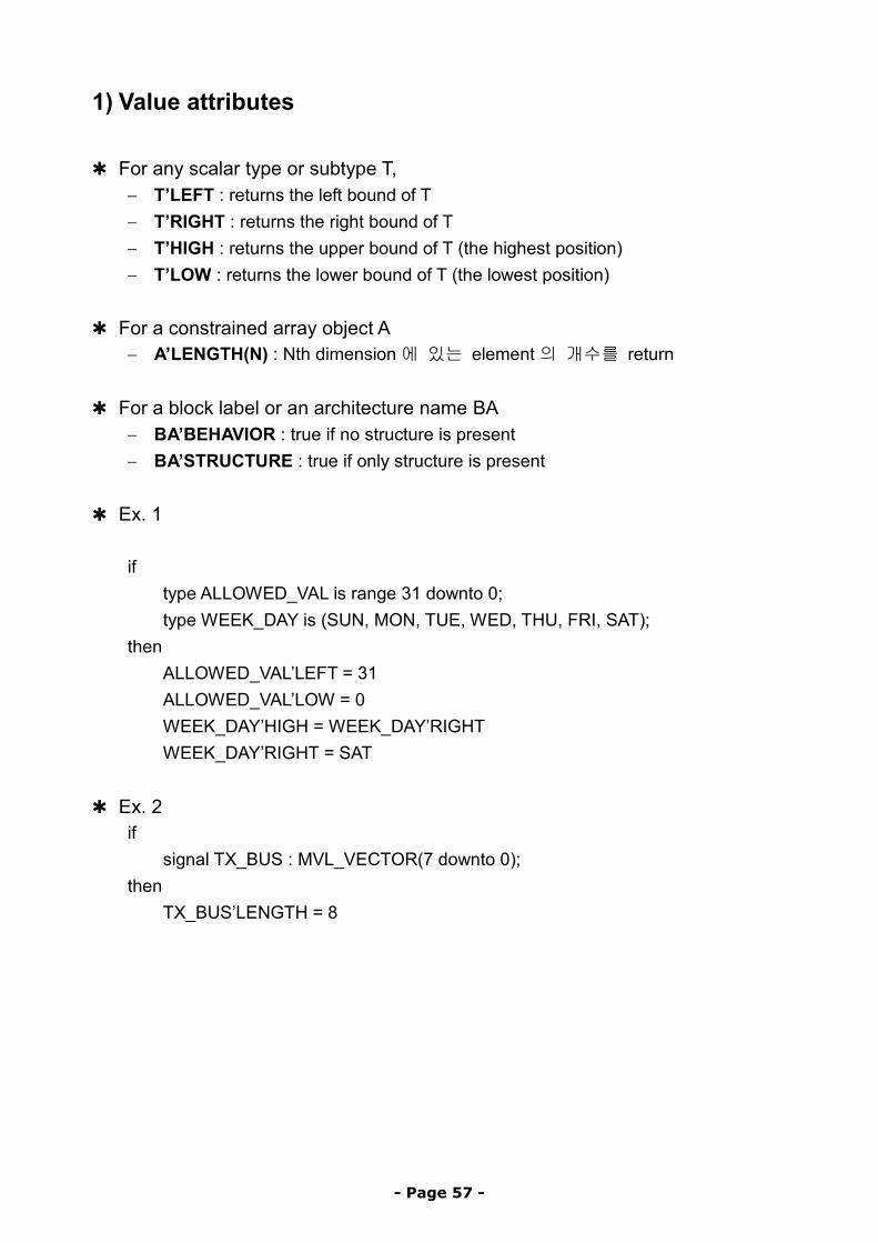
1) Value attributes ✱ For any scalar type or subtype T,
− T’LEFT : returns the left bound of T − T’RIGHT : returns the right bound of T − T’HIGH : returns the upper bound of T (the highest position) − T’LOW : returns the lower bound of T (the lowest position)
✱ For a constrained array object A
− A’LENGTH(N) : Nth dimension에 있는 element의 개수를 return ✱ For a block label or an architecture name BA
− BA’BEHAVIOR : true if no structure is present − BA’STRUCTURE : true if only structure is present
✱ Ex. 1
if type ALLOWED_VAL is range 31 downto 0; type WEEK_DAY is (SUN, MON, TUE, WED, THU, FRI, SAT);
then ALLOWED_VAL’LEFT = 31 ALLOWED_VAL’LOW = 0 WEEK_DAY’HIGH = WEEK_DAY’RIGHT WEEK_DAY’RIGHT = SAT
✱ Ex. 2
if signal TX_BUS : MVL_VECTOR(7 downto 0);
then TX_BUS’LENGTH = 8
- Page 57 -
2) Function attributes ✱ Represent function that are called to obtain a value
(used to convert values from an enum or physical type to an integer type) ✱ For discrete type, a physical type, or a subtype T
− T’POS(V) : return position number of V in T − T’VAL(P) : return value at position P in T − T’SUCC(V) : returns value in T which is on position higher than V − T’PRED(V) : returns value in T which is on position lower than V − T’LEFTOF(V) : returns value in T which is on position left from V − T’RIGHTOF(V) : returns value in T which is on position right from V
✱ Ex. 1
if subtype DLY_TIME is TIME range 50 ns downto 10 ns;
then DLY_TIMES’SUCC(21 ns) = 22 ns DLY_TIME’RIGHTOF(11 ns) = 10 ns
✱ For a constrained array object A
− A’LEFT(N) : returns the left bound of Nth dimension of A − A’RIGHT(N) : returns the right bound of Nth dimension of A − A’LOW(N) : returns the lower bound of Nth dimension of A − A’HIGH(N) : returns the upper bound of Nth dimension of A
✱ For a signal object S − S’EVENT : 현재 simulation시간에 signal S에 event가 있으면 true − S’ACTIVE : 현재 simulation시간에 signal S가 active이면 true − S’LAST_EVENT : S에 바로 이전 event이후 경과한 시간을 return − S’LAST_ACTIVE: S에 바로 이전 active했던 이후 경과한 시간을 return − S’LAST_VALUE : 바로 직전 event 이전에 S가 가졌던 값을 return
✱ Ex. 2
if signal CLOCK : BIT; signal COUNT : INTEGER;
then (CLOCK = ‘1’ and CLOCK’EVENT) -- rising edge on CLOCK (COUNT = 20 and COUNT’LAST_VALUE = 10)
- Page 58 -
3) Signal attributes ✱ Associated signals로 부터 새로운 signal을 만들어 냄
− Concurrent statement에서 사용되면 event를 발생시킴 ✱ For a signal object S
− S’DELAYED(T) : S에서 시간 T만큼 delay된 새로운 signal − S’STABLE(T) : S가 T에서 event를 갖지 않으면 true가 되는 boolean signal − S’QUIET(T) : S가 T에서 active되지 않으면 true가 되는 boolean signal − S’TRANSACTION : S가 active될 때마다 값이 바뀌는 bit type signal
✱ Ex. 1
if signal CLOCK_SKEW : BIT;
then CLOCK_SKEW’DELAYED(7 ns); CLOCK_SKEW’STABLE(6 ns);
4) Type attributes ✱ For any type or subtype T
− T’BASE : returns the base type of T
5) Range attributes
✱ For a constrained array object A
− A’RANGE(N) : returns the Nth index range of A − A’REVERSE_RANGE(N) : returns the Nth index range reversed
✱ Ex. 1
if variable WBUS : MVL_VECTOR (7 downto 0);
then for INDEX in WBUS’RANGE loop -- parameterized index for loop … end loop;
- Page 59 -
B) User-defined attributes
✱ User-defined attributes : constant of any type ✱ Attribute declaration : attribute name과 그 type을 다음과 같이 정의함
attribute attr-name : value-type; ✱ Attribute specification : attribute 이름과 값 assignment를 지정함
attribute attr-name of item-names : name-class is expression; ✱ Ex. 1
type FARADS is range 0 to 5000 units
pf; end units;
attribute CAPACITANCE : FARADS; -- attr. declaration attribute CAPACITANCE : FARADS of CLK, RESET : signal is 20 pf --attr. spec attribute CAPACITANCE : FARADS of all : variable is 0 pf; --item-name for all
✱ Attribute값은 item-name’attr-name 형태로 expression에서 사용 가능함 ✱ Ex. 2
signal CAP_VAL : FLOAT; … CAP_VAL <= 2*CLK’CAPACITANCE;
- Page 60 -
9. Modeling Techniques
9.1 Design Library 선정
1. Value System의 선택
1) Simulation시 어떤 value system을 사용할 것인가? 예) Predefined one, four-value system(0, 1, U, Z), or 9-value system,…
✴ 4-value system type MVL is (‘0’, ‘1’, ‘u’, ‘z’); type MVL_VECTOR is array (NATURAL range <> of MVL);
2) 만약 predefined system을 사용하지 않는 다면 a. Basic types을 새로이 정의하고, b. These types에 대한 기본 operation set을 정의해야 함
VHDL operators 모두에 대해 overloaded operators를 정의해야 함
2. Component package의 선택
− Structural modeling 을 하려면, 모든 component 의 component declaration 를 포함하는 package를 선택해야 함
✴ package for CMOS components (CMOSLIB, VTICMOS_LIB) ✴ package for TTL-7400 series components (TTLLIB) ✴ package for ECL components (ECLLIB)
- Page 61 -
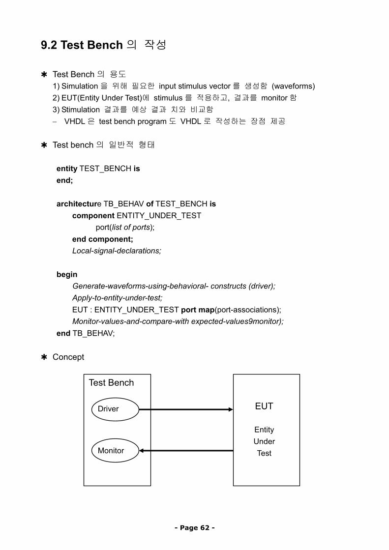
9.2 Test Bench의 작성
✱ Test Bench의 용도 1) Simulation을 위해 필요한 input stimulus vector를 생성함 (waveforms) 2) EUT(Entity Under Test)에 stimulus를 적용하고, 결과를 monitor함 3) Stimulation 결과를 예상 결과 치와 비교함 − VHDL은 test bench program도 VHDL로 작성하는 장점 제공
✱ Test bench의 일반적 형태
entity TEST_BENCH is end; architecture TB_BEHAV of TEST_BENCH is
component ENTITY_UNDER_TEST port(list of ports);
end component; Local-signal-declarations;
begin Generate-waveforms-using-behavioral- constructs (driver); Apply-to-entity-under-test; EUT : ENTITY_UNDER_TEST port map(port-associations); Monitor-values-and-compare-with expected-values9monitor);
end TB_BEHAV;
✱ Concept
EUT
EntityUnderTestMonitor
Driver
Test Bench
- Page 62 -
1) Waveform Generation ✱ Input stimulus를 생성하는 두 가지 방법
1) Waveforms을 아래 방법으로 만들어서 일정 시간 간격으로 적용 a) 반복 pattern 사용 b) A set vectors를 ASCII file에 저장하여 사용
2) Entity의 결과에 근거해서 stimulus를 생성함 (FSM testing에 유용)
a) 반복 patterns의 생성 ✱ Ex. 1 : A clock with a constant on-off delay
A <= not A after 20 ns; -- A to be of type BIT ✱ Ex. 2 : A clock with varying on-off day
process constant OFF_PERIOD : TIME := 30 ns; constant ON_PERIOD : TIME := 40 ns;
begin wait for OFF_PERIOD; D_CLK <= ‘1’; wait for ON_PERIOD; D_CLJ <= ‘0’;
end process; 또는 D_CLK <= ‘1’ after OFF_PERIOD when D_CLK = ‘1’ else
‘0’ after ON_PERIOD; ✱ Ex. 3 : Phase delayed clock from another clock;
DLY_D_CLK <= D_CLK’DELAYED(20 ns);
✱ Ex. 4 : 비 반복형 waveform
RESET <= ‘0’, ‘1’ after 100 ns, ‘0’ after 180 ns, ‘1’ after 210 ns;
- Page 63 -
b) Vector set의 사용
✱ Input vectors를 ASCII file에 저장하여 사용하는 예 process
type VEC_TYPE is file of BIT_VECTOR; file VEC_FILE : VEC_TYPE is in “/usr/jskim/EX1.vec”; variable LENGTH : INTEGER; variable IN_VECTOR : BIT_VECTOR ( 1 to 4);
begin LENGTH := 4; -- number of bits to be read while (not ENDFILE(VEC_FILE) loop
READ(VEC_FILE, IN_VECTOR, LENGTH); …
end loop; end process;
✱ Output 값을 file에 저장하는 예
architecture DIV_TB_BENCH of DIV_TB is component DIV
port (CK, RESET, TESTN L: in BIT; ENA : out BIT); end component; signal CLOCK, RESET, TESTN, ENABLE : BIT; type VEC_TYPE is file of BIT_VECTOR; file OUTFILE : VEC_TYPE is out “/usr1/jskim/div.vec.out”;
begin CKP: process
begin CLOCK <= ‘0’; wait for 5 ns; CLOCK <= ‘1’; wait for 5 ns;
end process CKP; RESET <= ‘1’, ‘0’ after 100 ns’ TESTN <= ‘0’, ‘1’ after 150 ns, ‘0’ after 600 ns; D1:DIV port map (CLOCK, TESET, TESTN, ENABLE); -- For every event on ENABLE output signal, write to file
MONITOR: process(ENABLE) begin
WRITE (OUTFILE, ENABLE); end process MONITOR;
end DIV_TB_BEH;
- Page 64 -
2) 결과 Monitoring ✱ Input vectors를 적용한 후 simulation 결과를 얻어서 예상 결과치와 비교함 ✱ Ex. (Input & output vectors를 tables에 저장함)
architecture DIV_TB_MON of DIV_TB is component DIV
port (CK, RESET, TESTN : in BIT; ENA : out BIT); end component; type BIT3 is array (1 to 3) of BIT; type BIT2_VEC is array(INTEGER range <>, INTEGER range <>) of BIT; constant IN_VEC : BIT2_VEC := (“100”, “100”, “100”, “110”, “111”, “011”); constant OUT_VEC : BIT2_vEC := “0”, “0”, “0”, “0” ,”1”); constant STROBE_DLY : TIME := 1ns; constant CYCLE_TIME : TIME := 100 ns; signal CLOCK, RESET, TESTN, ENABLE : BIT;
begin APP: process begin
for J in 1 to IN_VEC”LENGTH(1) loop P_1(DRV_SIG => CLOCK, SIG_VAL => IN_VEC(J,1), DRV_DLY => 20 ns, DRV_WID => 30 ns); -- procedure P_1이 clock을 생성함 RESET <= IN_VEC(J, 2); TESTN <= IN_VEC(J, 3); wait for (CYCLE_TIME - STROBE_DLY); assert ENABLE = OUT_VEC(J, 1); -- 결과 비교 wait for STROBE_DLY; -- 다음 vector를 위해 기다림
end loop; end process APP; -- Entity Under Test D2 : DIV port map (CLOCK, RESET, TESTN, ENABLE);
end DIV_TB_MON;
- Page 65 -
- Page 66 -
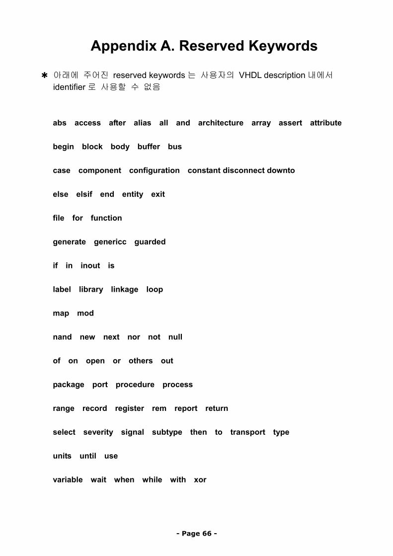
Appendix A. Reserved Keywords
✱ 아래에 주어진 reserved keywords는 사용자의 VHDL description내에서 identifier로 사용할 수 없음 abs access after alias all and architecture array assert attribute begin block body buffer bus case component configuration constant disconnect downto else elsif end entity exit file for function generate genericc guarded if in inout is label library linkage loop map mod nand new next nor not null of on open or others out package port procedure process range record register rem report return select severity signal subtype then to transport type units until use variable wait when while with xor