version 1.20 setup guide - canon...
TRANSCRIPT

CXDI Control Software NE
Setup GuideVersion 1.20
Before using this software, be sure to read this manual and the separate Operation Manual thoroughly.Also, read the Digital Radiography CXDI series User’s Manual.Keep the manual where it is easily accessible.
2
To the CustomersThank you for purchasing the Canon CXDI Control Software NE (hereinafter called this product).Operating instructions are divided into two volumes: the Operation Manual and the Setup Guide.Before using this product, be sure to read these manuals thoroughly in order to utilize this product more effectively.
Disclaimer
1. In no event shall Canon be liable for any damage or loss arising from fire, earthquake, any action or accident by a third party, any intentional or negligent action by the users, any trial usage, or other usage under abnormal conditions.
2. In no event will Canon be liable for direct or indirect consequential damage arising out of the use or unavailability of this product.Canon will not be liable for loss of image data due to any reason.
3. In no event shall Canon be liable for personal physical harm or property damage that is sustained when the instructions are not followed or the product is misused.
4. It is the responsibility of the attending physicians to provide medical care services. Canon will not be liable for the faulty diagnosis.
5. Roentgenography, image processing, image reading, and image data storage must be performed in accordance with the laws of the country or region in which the product is being used.The user is responsible for maintaining the privacy of image data.
6. Information in this manual may change without prior notice.
7. We’ve taken all possible means to ensure the content accuracy of this manual. If you have any questions or problems, contact your sales representative or local Canon dealer.
Trademarks• The Canon name and Canon logo are registered trademarks of Canon Inc.• Ethernet is a trademark of Xerox Corporation.• Microsoft and Windows are either registered trademarks or trademarks of Microsoft Corporation in the
United States and/or other countries or regions.• TrueType is a registered trademark of Apple Inc.• Intel and Intel Core are trademarks of Intel Corporation in the U.S. and other countries.• Other systems and product names in this manual are the trademarks of the manufacturers that have
developed them.
Copyright• All rights reserved.• Under copyright laws, this manual may not be reproduced, in whole or in part, without the written
permission of Canon.
Third Party SoftwareThird-party software will be installed on the image-capture computer when the control software is being installed by the service engineer. For details on the third-party software and its license agreements, consult your service engineer.

Safety SummaryBefore using this product, read this safety summary thoroughly. This information will prevent the users and persons involved from sustaining physical harm and/or property damage.Read the separate Operation Manual and the Digital Radiography CXDI series User’s Manual as well.
Safety NoticesThe following safety notices are used to emphasize certain safety instructions. This manual uses the caution symbol along with a caution message.
Safety PrecautionsFollow this safeguard and use the application software properly to prevent injury and equipment/data damage.
While conducting Calibration and Performance Test
CAUTIONThis notice is used to identify conditions under which improper use of the product may cause minor personal injury.
CAUTION
Be sure to confirm that there is no person in the radiology room during Calibration and Performance Test to prevent the possibility of any persons exposing themselves to X-ray exposure.
3

Contents
ContentsSafety Summary ............................................................................................................ 3
1 System Configurations and Requirements
1.1 Hardware configuration.......................................................................................... 8
1.2 Hardware requirements.......................................................................................... 9
1.3 Software requirements ......................................................................................... 10
2 System Setup Screen
2.1 Using the system setup screen............................................................................ 122.1.1 Basic operations..................................................................................................................... 122.1.2 System setup option finder.................................................................................................... 14
2.2 User Administration tab........................................................................................ 16
2.3 System Settings tab .............................................................................................. 182.3.1 System options ....................................................................................................................... 182.3.2 Monitor gamma....................................................................................................................... 20
2.4 Customize Display tab .......................................................................................... 222.4.1 GUI Color Taste Selection, Examination Screen, and Column Headers options ............. 222.4.2 Description List Items option ................................................................................................ 23
2.5 Annotation tab ....................................................................................................... 242.5.1 Preview Annotation tab.......................................................................................................... 242.5.2 Free Annotation/Laterality Marker tab ................................................................................. 262.5.3 Film Annotation tab ................................................................................................................ 28
2.6 Connection tab ...................................................................................................... 302.6.1 Storage tab.............................................................................................................................. 302.6.2 Printer tab................................................................................................................................ 332.6.3 MWL tab................................................................................................................................... 362.6.4 MPPS tab................................................................................................................................. 382.6.5 GenCom tab ............................................................................................................................ 392.6.6 Layout Template button......................................................................................................... 40
4
Contents
3 System Tools
3.1 Using the system tools ......................................................................................... 443.1.1 Basic operations..................................................................................................................... 443.1.2 System tool option finder....................................................................................................... 45
3.2 Process Viewer button.......................................................................................... 46
3.3 Protocol Editor button .......................................................................................... 483.3.1 Modifying the protocol ........................................................................................................... 483.3.2 Creating new protocols.......................................................................................................... 533.3.3 Modifying the category tabs.................................................................................................. 543.3.4 Packaging a set of protocols in a single protocol............................................................... 553.3.5 Creating new protocol trays .................................................................................................. 56
3.4 QC Tool button ...................................................................................................... 583.4.1 Calibrating the detector ......................................................................................................... 593.4.2 Inspecting the detector (Performance Test) ........................................................................ 623.4.3 Inspecting the detector/power box
(Self-diagnosis) ....................................................................................................................... 63
3.5 Image Proc button ................................................................................................ 66
3.6 DB Backup button................................................................................................. 713.6.1 Database Backup option........................................................................................................ 713.6.2 Output Exam Log option ........................................................................................................ 72
Appendix
1 Imaging Parameters............................................................................. 75
1.1 Overview of Imaging Parameters ........................................................................ 75
1.2 Classification of Imaging Parameters ................................................................. 75
1.3 Access Privileges .................................................................................................. 75
1.4 How to Access Imaging Parameters................................................................... 76
5
Contents
2 Saving Imaging Parameters ................................................................ 77
2.1 Adjustment and Saving of Default Parameters .................................................. 782.1.1 Adjustment .............................................................................................................................. 782.1.2 Saving ...................................................................................................................................... 78
2.2 Adjustment and Saving of Study Parameters..................................................... 782.2.1 Adjustment .............................................................................................................................. 782.2.2 Saving ...................................................................................................................................... 78
3 Details of Imaging Parameters............................................................ 79
3.1 Main Parameters ................................................................................................... 79
3.2 Description of Parameters ................................................................................... 80
3.3 Other Parameters.................................................................................................. 86
4 Adjustment Procedure......................................................................... 87
4.1 Default Parameters ............................................................................................... 87
4.2 Study Parameters.................................................................................................. 90
5 Technical Overview of Image Processing.......................................... 92
5.1 Overview of Image Processing ............................................................................ 92
5.2 Automatic Analysis................................................................................................ 935.2.1 Detection of Irradiated Fields ................................................................................................ 935.2.2 Image Feature Analysis.......................................................................................................... 945.2.3 Dynamic Range Analysis........................................................................................................ 95
5.3 Image Processing for Diagnosis.......................................................................... 965.3.1 Image Tone Transformation .................................................................................................. 965.3.2 Dynamic Range Adjustment .................................................................................................. 975.3.3 Image Enhancement............................................................................................................... 995.3.4 Noise Reduction ................................................................................................................... 100
6 Printing IP Parameter Values on printed images ............................ 101
7 Monitor Gamma Adjustment ............................................................. 104
Index ....................................................................................................... 108
6

1 System Configurations and
Requirements
1.1 Hardware configuration
1.2 Hardware requirements
1.3 Software requirements

1. System Configurations and Requirements
1.1 Hardware configuration
*1 Consists of DICOM standard compatible equipment (HIS/RIS, PACS, printer, storage device, etc).
*2 Recommended commercially available items
Detector
X-ray generator
CXDI Control Software NE installed image-capture computer
Hospital network*1
Power box
Up to 4 pairs of detectors and power boxes can be connected.
Wireless detector
Access point*2
Hub*2
X-ray I/F Box
8

1. System Configurations and Requirements
1.2 Hardware requirements
Image-capture computer- Intel® Core™2 Duo 2.0 GHz or faster processor- 4 GB of RAM- 50 GB of available hard-disk space
Display- XGA (1024×768), SXGA (1280×1024)- WXGA++ (910×804), WSXGA+ (1680×1050), WUXGA (1920×1200)- DICOM GSDF or DICOM P-value LUT compatible- Touch operation compatible
Video card- Graphic board- Screen resolution corresponding to that of the display- Full color (24 bits or more)
Ethernet- More than 3 ports (For a detector control, X-ray generator control, and Local Area
Network)A port for a detector requires Intel Pro/1000 PT (PCI Express)
Detector- Static flat-panel detector (Ethernet connection available)- Wireless flat-panel detector- Maximum number of detectors that can be configured: 10- Maximum number of detectors that can be simultaneously connected: 4
UPS (Uninterruptible Power Supply) (optional)
Bar-code reader (optional)- USB interface- USB bus power
Magnetic card reader (optional)
NOTE: For details about hardware requirements, consult your service engineer.
9

1. System Configurations and Requirements
1.3 Software requirements
Operating System- Microsoft Windows Vista Business Edition SP1 or later (×64)- Microsoft Windows Vista Ultimate Edition SP1 or later (×64)- Microsoft Windows 7 Professional Edition (×64)- Microsoft Windows 7 Ultimate Edition (×64)
Additional software- .Net Framework 3.5 SP1 or later- Microsoft Windows Vista Security Patch- Microsoft Windows 7 Security Patch- SQL Server 2005 Express Edition- DirectX Runtime- VC++ 2005 redistributable package- VC++ 2008 redistributable package
NOTE: For details about software requirements, consult your service engineer.
10

2 System Setup Screen
2.1 Using the system setup screen
2.2 User Administration tab
2.3 System Settings tab
2.4 Customize Display tab
2.5 Annotation tab
2.6 Connection tab

2. System Setup Screen
2.1 Using the system setup screenFundamental system setup options (user administration, screen appearance, and so on) are organized through the setup option tabs on the system setup screen. First learn basic operation in 2.1.1, and then access the necessary setup options as explained by the setup option finder in 2.1.2.
2.1.1 Basic operations
1 Show the system setup screen.
Click on the [EXAM] or [PAST] screen.
When [Connect GEN] appears
The image-capture computer and the X-ray generator have been functionally disconnected. Click [Connect GEN] to resume connection.
Note: [Connect GEN] appears only when the communication with the X-ray generating device is enabled. See 2.6.5 for details on operation.
(System setup button)
Setup option tabs
[EXAM] or [PAST] screen
System setup screen
Login user name
[Connect GEN]
12

2. System Setup Screen
2 Select a setup option.
Click the target setup option tab. For the Annotation and Connection tabs, a further click of a sub-tab is required.
NOTE: The User Administration tab is not available during examination.
To change the settings
See 2.2 thru 2.6.
To save the changes that have been made and continue with other settings
Click [Apply].
To save the changes and return to the previous [EXAM] or [PAST] screen
Click [OK]. The screen shown before clicking returns.
To cancel the changes and return to the previous [EXAM] or [PAST] screen
Click [Cancel]. The screen shown before clicking returns.
NOTE: After [Apply] is clicked, the changes cannot be canceled.
[Cancel]
[Apply]
[OK]
13

2. System Setup Screen
2.1.2 System setup option finder
The following system setup option tabs are available:
User Administration tab (See 2.2)
Addition, deletion, and modification of the user account
System Settings tab (See 2.3)
CXDI Control Software NE:Software Version, Character Set, and Device Info
Screen Saver: Wait Time and Auto-LogoutProcess Viewer: Refresh IntervalEssential Input Setting:
Essential items selection for the Patient/Study information pane
Institution: Institution NameMonitor Gamma: Confirmation of the monitor gamma adjustment using test
patterns
Customize Display tab (See 2.4)
GUI Color Taste Selection:Two options are available.
Examination Screen:Automatic Next Protocol Selection, Show Code Meaning, Input Reject Reason, Show Stitch Screen automatically after ending every Exam, Patient Info Input Mode, Help Display, and Measurement Object
Column Headers: For both the Worklist/Pendinglist and the Past ListDescription List Items:
Description list management for Referring Physician, Reading Physician, and Reject Reason
14

2. System Setup Screen
Annotation tab
The following sub-tabs are available.
Preview Annotation tab (See 2.5.1):Display item layout for single view mode, Font, and font size
Free Annotation/Laterality Marker tab (See 2.5.2):Font, font size, and Free Annotation list for Free Annotation Laterality marker selector, Font, font size, and Position for the laterality marker
Film Annotation tab (See 2.5.3):Embedded item layout, Font, and font size for each film/image (This tab is separated into Film Box Annotation and Image Box Annotation sub-tabs in accordance with the intended annotation object.)
Connection tab
The following sub-tabs are available.
Storage tab (See 2.6.1):Storage selection and communication tests, Storage List management, and Common Output Setting
Printer tab (See 2.6.2):Printer selection and communication tests, Printer List management, Common Output Setting and Layout Template selection (see 2.6.6)
MWL tab (See 2.6.3):MWL settings and communication tests, and Search Condition settings
MPPS tab (See 2.6.4):MPPS settings and communication tests
GenCom (See 2.6.5):X-ray generator communication selection
15

2. System Setup Screen
2.2 User Administration tabTo ensure the security of personal information and enable authenticated operation, the CXDI Control Software NE (hereinafter referred to as “Control Software”) provides a login dialog box on the start screen. The User Name for the user account created with this tab appears in the User Name selector on the start screen. A user without Security Administrations privileges can only modify his/her own user account settings.
NOTE: New user account registration requires the Security Administrations privilege (see step 2). Consult your service engineer.
User account list
[Delete]
[Add]
[Property]
Click to cancel registration.
[OK]
The available privileges are highlighted.
16

2. System Setup Screen
1 Register an user account to the User account list.
Click [Add] to create a new user account.
To modify an existing user account
Click the target user in the user account list, and then click [Property].
2 Enter or modify the user account properties.
User Name: Identifies users.Operator Name (for DICOM):
This entry is optional.Change Password Information:
Select this option before entering a new password.New Password: Enter the same password in the Retype Password
(Confirmation) field as well.Role: According to the role, advanced operations are permitted.
The following privileges can be granted to a role: Security Administrations (this section), ProtocolEdit Administrations (see 3.3), ImageProcessing Administrations (see 2.3.2 and 3.5), Calibration Administrations (see 3.4).
NOTE: In addition to Administrator and Standard User, the roles registered by the service engineer can be selected. For details, consult your service engineer.
NOTE: For User Name and Operator Name options, up to 64 alphanumeric characters can be used. For the New Password option, 4 to 64 alphanumeric characters can be used. Avoid use of blank character at the beginning of the name and password.
NOTE: The current login user cannot change his/her own Role option.
3 Set the user account.
Click [OK] in the Property dialog box.
To delete a user account
Click the target user in the user account list, click [Delete], and then click [OK] in the confirmation dialog box that appears.
17

2. System Setup Screen
2.3 System Settings tab
2.3.1 System options
CXDI Control Software NE
Software Version: Shows the version of the Control Software.Character Set: Shows the value of the character set for DICOM information.Device Info: Click to show the information dialog box for a connected
detector and power box. If two or more detectors are connected, a target detector selection is required on the Detector Name drop-down list of the dialog box. Click [OK] to close the dialog box.
Screen Saver
Wait Time: Specify the amount of time after the last operation until the screen saver becomes active (within a range of 1 to 60 minutes).
Auto-Logout: Select this option to automatically log out of the Control Software and activate the screen saver.This option may not be available depending on the Control Software setting. Consult your service engineer for the setting.
Process Viewer (See 3.2)
Refresh Interval: Specify the refresh interval for the process viewer (within a range of 1 to 60 seconds).
18

2. System Setup Screen
Essential Input Setting
Select the items required for the patient/study information pane. “*” appears at the left of the selected items in the patient/examination information pane, which indicates items that need to be entered before an examination is started. (refer to 3.2.1 in the Operation Manual).
Patient ID*, Name, Birth (birthday), Sex, Accession No., Referring Physician, Reading Physician, Study Description
* Required items that cannot be cleared.
Institution
Institution Name: Enter or modify the institution name to output as a film box annotation (see 2.5.3).
19
2. System Setup Screen
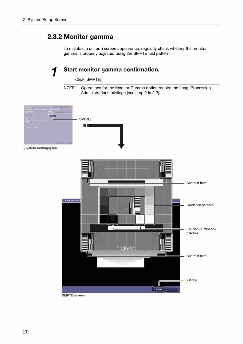
2.3.2 Monitor gamma
To maintain a uniform screen appearance, regularly check whether the monitor gamma is properly adjusted using the SMPTE test pattern.
1 Start monitor gamma confirmation.
Click [SMPTE].
NOTE: Operations for the Monitor Gamma option require the ImageProcessing Administrations privilege (see step 2 in 2.2).
[SMPTE]
[System Settings] tab
[Cancel]
Contrast bars
Gradation patches
5%, 95% luminance patches
Contrast bars
SMPTE screen
20
2. System Setup Screen
2 Check the screen appearance for the current monitor gamma.
Check whether the monitor gamma is properly adjusted using the three kinds of patches below.
To confirm the 5% and 95% luminance patches
Confirm that the squares inside each of the two luminance patches are clearly and equally defined.
To confirm the gradation patches
Confirm that the gradation patches are clearly defined.
To confirm the contrast bars
Confirm that the black and white strips are clearly defined.
3 End monitor gamma confirmation.
Click [Cancel] to return to the [System Settings] tab.
NOTE: Depending on the current software configuration, users can adjust the monitor gamma and save the adjustment result (see 7 in Appendix for details) in addition to confirming the monitor gamma using the SMPTE test pattern.
21

2. System Setup Screen
2.4 Customize Display tab
2.4.1 GUI Color Taste Selection, Examination Screen, and Column Headers options
GUI Color Taste Selection
Select either Warm Taste (when using in a dimly-lit room such as a radiology room) or Cool Taste (when using in a well-lit room such as a hospital ward in which X-ray exposure is available using a mobile system).
Examination Screen
Automatic Next Protocol Selection:Select the check box to automatically prepare the next available protocol for exposure. Clear the check box to manually select the next protocol to be conducted.
Show Code Meaning:Select the check box to use Code Meaning for the protocol title (except for protocols created on the Protocol Editor screen).
Input Reject Reason:Select the check box to enable entry of a Reject Reason.
Show Stitch Screen automatically after ending every Exam:Select the check box to automatically show the stitch screen when the number of images required for stitch protocol have been captured.
Patient Info Input Mode:Select either Birth (uses a birthday for the patient information) or Age (uses an age for the patient information).
NOTE: Even when Age is selected for the Patient Info Input Mode option, the information is not shown in the Patient List as it does not accurately specify the patient age.
Available column headers
[Add]
Text box[Remove]
22

2. System Setup Screen
Help Display: Select the position of the help display in the image view pane during image processing operations from among Top, Middle, or Bottom.
Measurement Object:Specify the details of objects embedded in Measurement mode. Line Width (of the distance/angle object), Unit (select from among “mm”, “cm” and “inch”) (refer to 6.3 in the Operation Manual), Font (font name), and Size (font size)
Column Headers
Select Worklist or Past List, and then select column headers to show for the selected list. Available column headers for each list are as follows:Worklist: Accession No.*, Study DateTime* (of the ordered
examination), Patient ID*, Name*, Study Status, Study Date, Study Time, Sex, Birth (birthday), Height, Weight, Referring Physician, Requesting Physician, Comment, Image Counter, RP ID (requested procedure ID), Pregnancy Status, SPS Description (scheduled procedure step description), and RP Description (requested procedure description)
Past List: Accession No.*, Study DateTime*, Patient ID*, Name*, Birth*, Print Result, Store Result, Study Date, Study Time, Image Counter, Sex, SC (storage commitment), and Reject
* Required items that cannot be cleared.
2.4.2 Description List Items option
The descriptions of reject reasons are preset in this option, as are the names of the referring physicians and reading physicians.
1 Select the target option.
Select Referring Physician, Reading Physician, or Reject Reason.
2 Add a new description to the list.
Enter a new name or description in the text box, and then click [Add].
To delete an description from the list
Click a name or description in the list to select it, and then click [Remove].
23

2. System Setup Screen
2.5 Annotation tab
2.5.1 Preview Annotation tab
Annotations superimposed on a preview image are selected and arranged on the Preview Annotation tab.
NOTE: The user can choose to have annotations always displayed on the screen,
independent of the status. For details, consult your service engineer.
1 Select the position of the annotations.
Select Top/Left, Bottom/Left, Top/Right, or Bottom/Right at the corners of the preview pane.
2 Specify the Font and the size option.
Perform this procedure while checking the preview pane.Click the Font drop-down arrow, and then select an option from the list.Click the size drop-down arrow, and then select an option from the list.
Font and size option
Positions
Selected position is shown.
[Blank line]
Selected item list
[Add][Remove]
[Up]
[Down]
Available annotation list
[Annotation > Preview Annotation] tab
Preview pane
Positions
24

2. System Setup Screen
3 Reserve the target annotations for the selected position.
Select from among the available annotation list, and then click [Add]. The selection appears in the selected item list.
Available annotations for each position (Preview Annotation tab)
Top/Left: Patient ID*, Patient Name*, Birth (birthday), Age, SexBottom/Left: Acquisition Time*, Total Exposure Time*, Total DAP*
(Dose Area Product), Total Absorbed Dose*, Total Air Kerma*, Free HDD Space*, Acquisition Date, Study Description
Top/Right: KVP* (kilo-voltage peak), Exposure Time*, X-ray Tube Current*, mAs*, SID (Source image receptor distance), SOD (Source object distance)
Bottom/Right: REX* (Reached Exposure value), EI* (Exposure Index), DI* (Deviation Index), EIt (See step 3 in 3.5 for details on EI, DI, and EIt.)
* Shown by default.
NOTE: Because the same annotation cannot be used twice, previously selected annotations are excluded from the available annotation list.
To remove annotations from the selected item list
Click the target annotations to highlight them, and then click [Remove]. Clicking on a highlighted annotation unselects it.
To add blank annotations
Click [Blank line] to add a blank annotation to the selected item list.
To show only the value without the annotation title
Clear the check box for the target annotation on the selected item list.
4 Change the order of annotations.
Click the target annotation to highlight it, and then click [Up] or [Down].
25

2. System Setup Screen
2.5.2 Free Annotation/Laterality Marker tab
In addition to the annotations preset in the Preview Annotation tab and the Film Annotation tab, custom annotations can be created ahead of time for the Annotation dialog box; they are embedded on both the screen preview and film sheet images (refer to 6.4 in the Operation Manual).Furthermore, the font type and font size of the free annotations and the laterality marker can be selected in this tab. The position of the laterality marker can also be specified (refer to 6.1.2 in the Operation Manual).
1 Enter a free annotation.
Enter a free annotation in the text box, and then click [Add]. The annotation appears in the free annotation list.
NOTE: Make sure that the length of annotations is as short as possible so that they do not overlap each other and overflow the preview pane.
To remove annotations from the free annotation list
Click the target annotation to highlight it, and then click [Remove]. A click of a highlighted annotation unselects it.
[Remove]
Free annotation list
[Add]
Preview pane
[Up]
[Down]
Text box
[Annotation > Free Annotation/Laterality Marker] tab
Laterality marker selector
26

2. System Setup Screen
2 Specify the Font and size options (only for free annotations).
Perform this procedure while checking the preview pane.Click the Font drop-down arrow, and then select an option from the list.Click the size drop-down arrow, and then select an option from the list.
3 Change the order of annotations in the free annotation list.
Click the target annotation to highlight it, and then click [Up] or [Down]. The order arranged in this tab will be reflected in the list in the Annotation dialog box.
4 Select the target laterality marker.
Select a marker in the laterality marker selector.
5 Specify the Font and size options (only for laterality markers).
Perform this procedure while checking the preview pane.Click the Font drop-down arrow, and then select an option from the list.Click the size drop-down arrow, and then select an option from the list.
6 Specify the position of the laterality marker.
The position of a laterality marker applied by clicking [L] or [R] in the toolbar can be specified (refer to 6.1.2 in the Operation Manual).Click the Position drop-down arrow, and then select an option from the list.
27

2. System Setup Screen
2.5.3 Film Annotation tab
Annotations embedded on each printed image and margin on a film are selected and arranged on the two sub-tabs under the Film Annotation tab. The annotations to be set on the Film Box Annotation tab are applied on each film margin, and those to be set on the Image Box Annotation tab are applied on each image.Although the Image Box Annotation tab differs from the Film Box Annotation tab in the position and number of available annotations, operations on these sub-tabs are the same. In this section, the Film Box Annotation tab is used for explanation.
1 Select the position of the annotations.
Select Top/Left, Bottom/Left, Top/Right, or Bottom/Right at the corners of the preview pane. Additionally, Top/Center and Bottom/Center options are available for the Film Box Annotation.
2 Specify the Font and the size option.
Perform this procedure while checking the preview pane.Click the Font drop-down arrow, and then select an option from the list.Click the size drop-down arrow, and then select an option from the list.
NOTE: For image box annotations, each font size of the annotation is reduced depending on the layout partition.
NOTE: The actual size of the annotations cannot be previewed on the preview pane of the Film Annotation tab.
Font and size option
Film Box Annotation/Image Box Annotation tabs
Selected position is shown.
[Blank line]
Selected item list
[Add][Remove]
[Up]
[Down]
Available annotation list
Positions
[Annotation > Film Annotation > Film Box Annotation] tab
FreeText1/2
Positions
Preview pane
28

2. System Setup Screen
3 Reserve the target annotations for the selected position.
Select from among the available annotation list, and then click [Add]. The selection appears in the selected item list.
To add free annotations
Select the FreeText1/2 text box and enter/modify a text before selecting FreeText1/2 from the available annotation list.
To add blank annotations
Click [Blank line] to add a blank annotation to the selected item list.
Available annotations for each position (Film Box Annotation tab)
The following items can be superimposed at all corners and Top/Center and Bottom/Center of a film.Patient ID*, Patient Name*, Birth (birthday), Age, Sex, Height, Weight, Accession No., Study Date, Study Time, Study Description, Referring Physician, Reading Physician, Operator, Institution Name*, Comment, FreeText1, FreeText2
Available annotations for each position (Image Box Annotation tab)
The following items can be superimposed at all corners of an image.Patient ID, Patient Name, Birth (birthday), Age, Sex, Height, Weight, Accession No., Study Date, Study Time, Study Description, Referring Physician, Reading Physician, Operator, Institution Name, Comment, IP Parameter, FreeText1, FreeText2, Detector Name, Protocol Name, Body Part, View Position, Series Description, KVP*, Exposure Time*, X-ray Tube Current*, mAs*, Series Date*, Series Time*, Acquisition Date, Acquisition Time, Grid, Focal Spot Size, Code Meaning, SID, SOD, Absorbed Dose*, DAP*, AirKerma*, REX, EI*, DI*, EIt* Shown by default.
The IP Parameter option available for Image Box AnnotationIf the IP Parameter option is selected, the values and options for image processing parameters that are applied to the image will be printed on the printed film. For details on the meaning of the printed values, see 6 in Appendix.
NOTE: Because the same annotation cannot be used for two or more positions, previously selected annotations are excluded from the available annotation list.
To remove annotations from the selected item list
Click the target annotations to highlight them, and then click [Remove]. Clicking on a highlighted annotation unselects it.
To show only the value without the annotation title
Clear the check box for the target annotation on the selected item list.
29
2. System Setup Screen
2.6 Connection tab
2.6.1 Storage tab
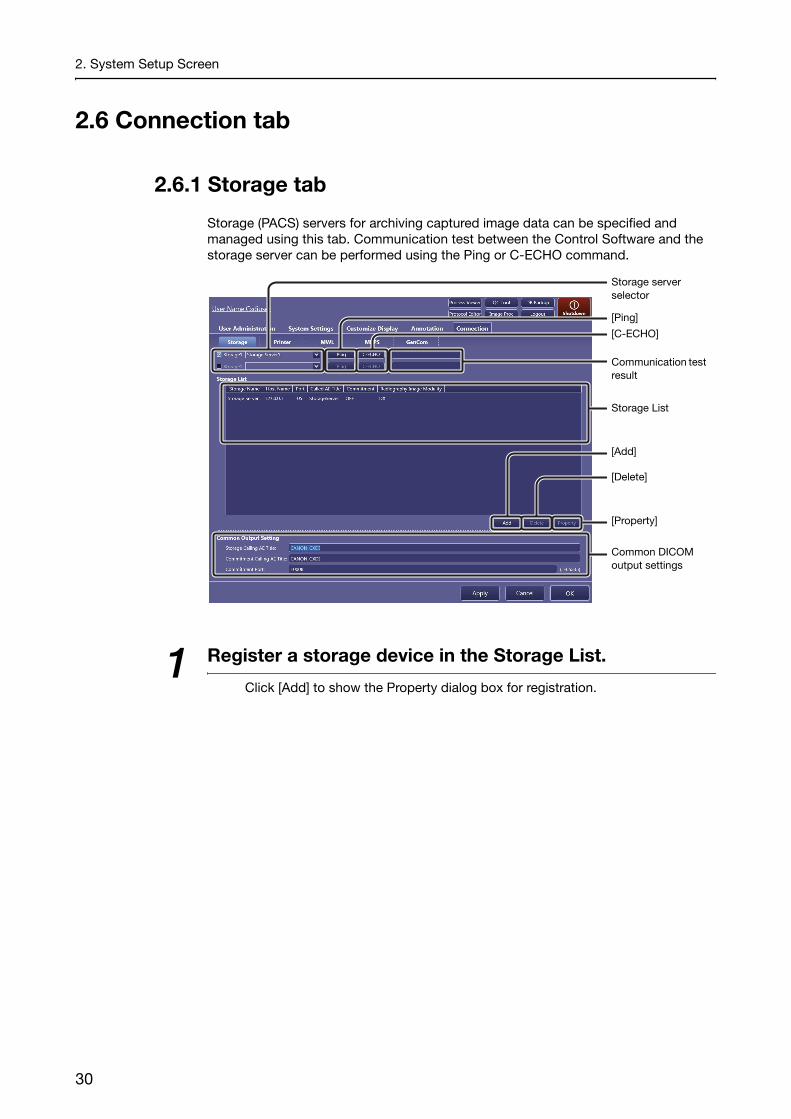
Storage (PACS) servers for archiving captured image data can be specified and managed using this tab. Communication test between the Control Software and the storage server can be performed using the Ping or C-ECHO command.
1 Register a storage device in the Storage List.
Click [Add] to show the Property dialog box for registration.
[Ping]
Storage server selector
[C-ECHO]
Communication test result
Storage List
[Add]
[Delete]
[Property]
Common DICOM output settings
30

2. System Setup Screen
To modify an existing storage server
Click the target storage server in the Storage List, and then click [Property].
2 Enter or modify the storage server properties.
Storage Name: Arbitrary name that identifies the storage serverHost Name: The IP address or the host name of the storage serverPort: Port number for the storage serverCalled AE Title: Application entity title assigned to the storage server
necessary for DICOM communicationRadiography Image Modality:
Select the modality of the images to be transmitted to the storage server.
Use GSPS: GSPS (Grayscale Softcopy Presentation State) service provides the consistency in the presentation of every screen and printed images. Select this option for the use of GSPS service.
To ensure image data storage using the storage commitment function
The Control Software can request the storage (PACS) server to securely store the image data. To do so, select the Storage Commit option, and then enter the properties as in step 2 above.After the function is enabled, when “Committed” is displayed for the SC status on the Study List in the [PAST > Past List] screen, the image data has been secured.Note that storage commitment setting needs to be enabled on both the Control Software and the destination storage server to use this function.
Click to cancel the operation.
[OK]
Use GSPS option
Storage Commit option
Storage Commitment properties
Storage server properties
[Ping][C-ECHO]
Radiography Image Modality selector
Continued
31

2. System Setup Screen
SC (storage commitment) status on the Study List in the [PAST > Past List] screenThe result for the storage commitment status can be confirmed by checking the SC status on the Study List in the [PAST > Past List] screen. To show the SC column header, select SC for the Past List under the Column Headers option (see 2.4.1).
To test communication between the Control Software and the storage server being registered
Click [Ping] to test the TCP/IP connectivity.Click [C-ECHO] to test the DICOM communication.The result of the test will be shown to the right of each test button.
3 Set the properties.
Click [OK]. If required, repeat steps 1 thru 3 for another registration. Up to five storage devices can be registered in the Storage List.
To change the order of header items in the Storage List
Drag a header item and drop it in the target position.
To delete storage server data in the Storage List
Click the target data to select, and then click [Delete].
4 Select the storage server to be used.
Select the storage server selector check box, click on the drop-down arrow, and select an option from the list (the storage servers registered in the Storage List are listed). Up to two storage servers can be used simultaneously.
To disable the storage server in use
Clear the target storage server selector check box.
To test communication between the Control Software and the storage server in use
Click [Ping] to test the TCP/IP connectivity.Click [C-ECHO] to test the DICOM communication.The results of both [Ping] and [C-ECHO] tests will be shown to the right of [C-ECHO].
NOTE: If the Called AE Title or the Port setting is modified during the commitment process, the process may fail.
NOTE: Even if some images are transmitted or an examination is in operation, modification or deletion of the registered storage server does not affect the current operation.
32

2. System Setup Screen
5 Modify the DICOM storage service properties.
Storage Calling AE Title:Application entity title assigned to the Control Software necessary for the DICOM storage service
Commitment Calling AE Title:Application entity title assigned to the Control Software necessary for the DICOM storage commitment service
Commitment Port:Port number for the DICOM storage commitment service
NOTE: If the Storage Calling AE Title or the Commitment Calling AE Title setting is modified during image data transmission, the process may fail.
2.6.2 Printer tab
Printers can be specified and managed using this tab. Communication test between the Control Software and the printer can be performed using the Ping or C-ECHO command. Custom layout templates for printout image can be created. See 2.6.6 for details on operation.
[Ping]Printer selector
[C-ECHO]
Communication test result
Printer List
[Add]
[Delete]
[Property]
Common DICOM output settings
[Layout Template]
Continued
33
2. System Setup Screen
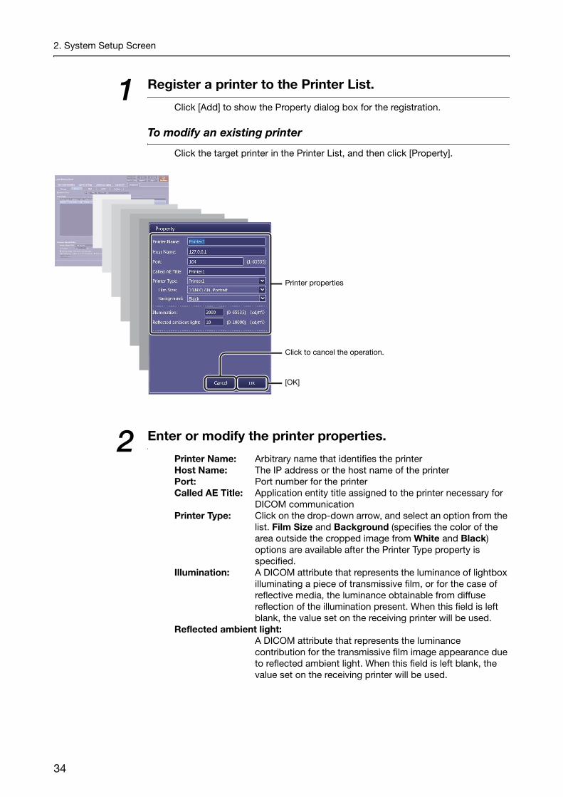
1 Register a printer to the Printer List.
Click [Add] to show the Property dialog box for the registration.
To modify an existing printer
Click the target printer in the Printer List, and then click [Property].
2 Enter or modify the printer properties.
Printer Name: Arbitrary name that identifies the printerHost Name: The IP address or the host name of the printerPort: Port number for the printerCalled AE Title: Application entity title assigned to the printer necessary for
DICOM communicationPrinter Type: Click on the drop-down arrow, and select an option from the
list. Film Size and Background (specifies the color of the area outside the cropped image from White and Black) options are available after the Printer Type property is specified.
Illumination: A DICOM attribute that represents the luminance of lightbox illuminating a piece of transmissive film, or for the case of reflective media, the luminance obtainable from diffuse reflection of the illumination present. When this field is left blank, the value set on the receiving printer will be used.
Reflected ambient light:A DICOM attribute that represents the luminance contribution for the transmissive film image appearance due to reflected ambient light. When this field is left blank, the value set on the receiving printer will be used.
Click to cancel the operation.
[OK]
Printer properties
34

2. System Setup Screen
3 Set the properties.
Click [OK]. If required, repeat steps 1 thru 3 for another registration. Up to five printers can be registered to the Printer List.
To change the order of header items in the Printer List
Drag an item and drop it in the target position.
To delete a printer from the Printer List
Click the target printer to select, and then click [Delete].
4 Select a printer to be used.
Click the drop-down arrow, and then select an option from the list (the printers registered in the Printer List are listed).
To disable a printer in use
Clear the printer selector check box.
To test communication between the Control Software and the printer in use
Click [Ping] to test the TCP/IP connectivity.Click [C-ECHO] to test the DICOM communication.The results of both [Ping] and [C-ECHO] tests will be shown to the right of [C-ECHO].
NOTE: Even if some images are transmitted or an examination is in operation, modification or deletion of the printer does not affect the current operation.
5 Modify DICOM print service properties and other options.
Printer Calling AE Title:Application entity title assigned to the Control Software necessary for the DICOM print service
Zoom Ratio: Specify the actual image size in %. A change made for this option reflects the setting of the Zoom Ratio option in the image arrangement screen. Refer to step 3 in 7.1.1 in the Operation Manual.
Show the image arrangement screen at output:Select this option to show the image arrangement screen before printing images on film sheets. Refer to 7.1.1 in the Operation Manual.
Selected exposure mode to be printed automatically:Select the Radiography check box to use the automatic arrangement feature. Refer to 7.1.1 in the Operation Manual.
35

2. System Setup Screen
2.6.3 MWL tab
The Modality Work List (MWL) service provides central data entry (ordering and scheduling of examinations) and management features. The HIS/RIS database server, which provides the MWL service, can be specified using this tab. Communication test between the Control Software and the database can be performed using the Ping or C-ECHO command.
NOTE: To show the MWL tab, start the Control Software after connecting the control PC to the HIS/RIS database.
1 Specify a database server for the MWL service.
Select the Use MWL check box, and then enter the following properties:Host Name: The IP address or the host name of the serverPort: Port number for the serverCalled AE Title: Application entity title assigned to the server necessary for
DICOM communicationCalling AE Title: Application entity title assigned to the Control Software
necessary for the DICOM MWL service
To disable the server in use
Clear the Use MWL check box.
To test communication between the Control Software and the server
Click [Ping] to test the TCP/IP connectivity.Click [C-ECHO] to test the DICOM communication.The results of both [Ping] and [C-ECHO] tests will be shown to the right of [C-ECHO].
Use MWL option
Search conditions
Communication test result
[C-ECHO]
[Ping]
MWL service properties
36

2. System Setup Screen
2 Specify preset narrowing conditions during study order acquisition.
The narrowing conditions below are applied every time the worklist is refreshed.Enter or select any narrowing conditions under the Search Condition title.AE Title: Application entity title assigned to the study necessary for
DICOM communicationStation Name: An institution defined name for the modality on which the
ordered study is to be performedLocation: The location at which the ordered study is to be performedPerform Physician:
Name of the physician scheduled to administer the ordered study
Time Range: Relative 1 and Relative 2 refer to the period relative to the current day or time in which the study orders are to be conducted. Relative 1 and Relative 2 are specified by days and hours respectively in the past/future. To clear the Time Range condition, select All.
Modality: DX refers to digital X-ray radiography, and CR to computed radiography. To cancel the condition, clear the check box.
NOTE: The Time Range option can be temporarily changed. Refer to 3.1.1 in the Operation Manual.
37

2. System Setup Screen
2.6.4 MPPS tab
The Modality Performed Procedure Step (MPPS) service provides a communication feature between the modality and the HIS/RIS database server that exchanges the status of ordered studies, such as in progress, completed, and so on to refresh the related information, including the worklist. The HIS/RIS database server, which provides the MPPS service, can be specified using this tab. Communication test between the Control Software and the database can be performed using the Ping or C-ECHO command.
NOTE: To show the MPPS tab, start the Control Software after connecting the control PC to the HIS/RIS database.
1 Specify a database server for the MPPS service.
Select the Use MPPS check box, and then enter the following properties:Host Name: The IP address or the host name of the serverPort: Port number for the serverCalled AE Title: Application entity title assigned to the server necessary for
DICOM communicationCalling AE Title: Application entity title assigned to the Control Software
necessary for the DICOM MPPS service
To disable a server in use
Clear the Use MPPS check box.
To test communication between the Control Software and the server
Click [Ping] to test the TCP/IP connectivity.Click [C-ECHO] to test the DICOM communication.The results of both [Ping] and [C-ECHO] tests will be shown to the right of [C-ECHO].
Use MPPS option
Communication test result
[C-ECHO]
[Ping]
MPPS service properties
38

2. System Setup Screen
2.6.5 GenCom tab
Communication between the Control Software and the X-ray generating device can be set using this tab.Detector settings are indicated on the examination screens by the communication (refer to 4.1 in the Operation Manual).
1 Enable the communication with the X-ray generating device.
Select the Communicate with the x-ray generating device check box.
To disable the communication with the X-ray generating device
Clear the Communicate with the x-ray generating device check box.
Click to cancel the operation.
[OK]
Communicate with the x-ray generating device option
[Apply]
39

2. System Setup Screen
2.6.6 Layout Template button
Custom templates can be created on this screen in order to arrange images on a film sheet.
1 Show the Layout Template screen.
Click [Layout Template] (see also step 5 in 2.6.2).
NOTE: The 8 basic templates cannot be selected, modified, or deleted.
[Layout Template]
Thumbnails for 8 basic templates
[Connection > Printer] tab
[New]
[Edit]
[Delete]
[Exit]
40

2. System Setup Screen
2 Enable template edit mode.
To create a custom template
Click [New]. The basic template 1×1 (horizontal × vertical) appears in place of the template thumbnails.
To modify an existing custom template
Click the target custom template to highlight it, and then click [Edit].
3 Select the target segment(s) to be modified.
To divide the segment
Click a single segment to highlight it in blue.
Divide Grid option
Basic template 1x1 Ex: Modify to create template 2x1
Border Width option[Reset]
[OK]
Click to cancel the operation.
[Divide], [Merge]
Continued
41

2. System Setup Screen
To merge the segments
Click the target and the neighboring segment to highlight them in blue. Note that a third click cancels the selection.
4 Modify the segment(s).
To divide the segment
Specify the number of segments to be created in the target segment, and then click [Divide].Click on the drop-down arrow of the Divide Grid option, and select an option from the list.The number of horizontal divisions can be set using the left-hand drop-down arrow, and the number of vertical divisions using the right-hand drop-down arrow.
To merge the segments
Click [Merge].
To modify the border width
Click on the drop-down arrow for the Border Width option, and select an option from the list.
To restore the original template
Click [Reset].
5 Continue modifications.
If necessary, repeat steps 2 thru 4.
6 Set the newly created or modified custom template.
Click [OK]. The newly created template thumbnail is added to the list. When an existing custom template is modified, the changes are reflected in the original template.
To delete an existing custom template
Click the target custom template to highlight it, click [Delete] and then click [OK] in the confirmation dialog box that appears.
7 Return to the [Connection > Printer] screen.
Click [Exit].
42

3 System Tools
3.1 Using the system tools
3.2 Process Viewer button
3.3 Protocol Editor button
3.4 QC Tool button
3.5 Image Proc button
3.6 DB Backup button

3. System Tools
3.1 Using the system toolsThe technical system setup options (for modification of protocols, image quality assurance, and so on) can be accessed from the system tool buttons. First learn basic operation in 3.1.1, and then access the necessary setup options guided by the system tool option finder in 3.1.2.
3.1.1 Basic operations
1 Show the system setup screen.
Click on the [EXAM] or [PAST] screen.
(System setup button)
[Cancel]
[EXAM] or [PAST] screen
System setup screen
System tool buttons
44

3. System Tools
2 Access the target system setup tool.
Click the target system tool button.
NOTE: The available system tool buttons vary depending on the privileges granted to a user (see step 2 in 2.2). [QC Tool] is disabled during examination, and [Protocol Editor] and [Image Proc] are disabled during examination and image review.
To use the tools
See 3.2 thru 3.6.
To return to the previous [EXAM] or [PAST] screen
Click [Cancel]. The screen shown before clicking returns.
3.1.2 System tool option finder
Process Viewer button (See 3.2)
Confirmation of the status of the data transmission process
Protocol Editor button (See 3.3)
Addition, modification, bundled selection and deletion of protocols, and configuration of the protocol listProtocol Settings:
Protocol Name, Comment, Code Value, Code Meaning, Laterality Marker, Body Part, Patient Orientation, Laterality (Marker Placement, DICOM Attribute), Default Workspace
Protocol Workspace Settings:Flipping and Rotation, Grid Name, Printable area of an oversized image
APR Editor: Exposure type, Source object distance(SOD), Source imaging receptor distance(SID), APR ID
QC Tool button (See 3.4)
Calibration: Creation of detector correction data for securing image quality. During Calibration, X-ray exposure is required.
Performance Test:Check of the detector and image quality. During the Performance Test, X-ray exposure is required.
Self-diagnosis: Check of the detector and image quality using test patterns and other images. During Self-diagnosis, X-ray exposure is not required.
Image Proc button (See 3.5)
Modification of the image processing parameters included in the protocol
Continued
45

3. System Tools
DB Backup button (See 3.6)
Database Backup, Output Exam Log
Logout button (Refer to 2.2 in the Operation Manual)
Logout from the Control Software.
button (Refer to 2.2 in the Operation Manual)
Shutdown the image-capture computer.
3.2 Process Viewer buttonThe current status and result of an image/arranged images (film sheet)/study/PPS data transmission can be confirmed in the process viewer. Users can manually resend data that was not transmitted and can also stop or cancel data being processed. See also 2.3 for details on the refresh interval for the process list.
Performed Procedure Step (PPS)The data to be transmitted to the RIS database that indicates the completion of the ordered study. This data is used for updating the worklist and so on.
1 Utilize the process list.
To sort the listed data
Click a sort item in the column head. To switch between ascending and descending sort order, click the same item again.
[Suspended]/[In Process]
Column head
Process list
[Detail]
[Retry]
[Delete]
[Exit Process Viewer]
Process viewer
46

3. System Tools
To rearrange the order of the column head items
Drag an item and drop it in the target position.
Classification of processesThe following appear in the Status column;Idling: The data is waiting to be transmitted.Processing: The data is being processed.Sending: The data is being transmitted.Error: The data transmission failed.
To select the target data
Click the target data to highlight it. To unselect the data, click it again.
2 Check the details of the target data.
Click the target data in the list, and then click [Detail].
To delete the target data
Click the target data, and then click [Delete].
3 Resend the target data.
Click the data with an Error indication in its Status column, and then click [Retry].
4 Suspend target data by study.
Click the data with a Processing or Sending indication in its Status column, and then click [Suspended].
To restart suspended process
Click the suspended data, and then click [In Process].
5 Exit the process viewer.
Click [Exit Process Viewer].
47

3. System Tools
3.3 Protocol Editor buttonPreset protocols are organized on the protocol tray (refer to 3.1.5 in the Operation Manual) and users can create and modify study orders using the tray. When new protocols or new trays are required for suite on-site operations, follow the steps below.
NOTE: Operations for this tool require the ProtocolEdit Administrations privileges (see step 2 in 2.2).
3.3.1 Modifying the protocol
1 Select the target protocol.
Click the target tab and then a protocol in the protocol tray. The protocol for the corresponding protocol listed in the protocol list pane are highlighted.
To change the position of the protocol in the protocol tray
While the target protocol is selected in the protocol tray, click [Move]. [Move] changes to [Cancel] and available destinations indicated by blank rectangles appear in the protocol tray. Click the target destination.To cancel the modification, click [Cancel] before clicking the target destination.
NOTE: Protocols can be moved to other trays as well as the current tray. In such cases, select the target tab before selecting the target destination.
Protocol tray
[Move]/[Cancel]
Click to scroll the category tabs.
Category tabs Protocol list pane
Protocol Editor screen
Click to show and hide the protocols.
[Edit]
Protocol
[Remove][Exit]
48

3. System Tools
To delete the protocol in the protocol tray
While the target protocol is selected in the protocol tray, click [Remove], and then click [OK] in the confirmation dialog box that appears.
2 Modify the protocol/protocol group properties.
Click [Edit] while in workspace edit mode, and then modify the properties.
NOTE: Protocols in the protocol list pane have the following two modes. Available operations for the protocol varies depending on the mode.
Protocols that have the same conditions but different workspaces are displayed as a protocol group.To enter workspace edit mode, click the protocol. To enter protocol group edit mode, click the area outside the protocol.
Workspace edit mode Protocol group edit mode
Protocol group
[Remove]
[Property]
ExposureProtocol Code list
[Add]
Click to cancel the modification.
[Next]/[OK]
Protocol property screen 1
Continued
49

3. System Tools
Protocol Settings
Protocol Name: Arbitrary name that identifies the protocolComment: Arbitrary commentExposure Protocol Code:
See “To modify a protocol code meaning” below for details.Laterality Marker:
Select the Embed L (shows the L marker at the preset position) or Embed R (shows the R marker at the preset position) check box. For details on the preset position, see 2.5.2.
Body Part*: Click on the drop-down arrow, and select an option from the list.
Patient Orientation*:Click on the drop-down arrow, and select an option from the list.L (left), R (right), H (head), F (foot), P (posterior), A (anterior), and a combination of these are available.
Laterality*: Select the Laterality attribute from L (left body part), R (right body part), Both L and R (left and right body parts), Unpaired (body part without laterality attribute).To associate the Laterality Marker option defined marker with a DICOM attribute in the event of transmission, select the Use Laterality Marker as the DICOM Attribute option. Refer to 6.1.2 in the Operation Manual for details on embedding laterality markers.
Default Workspace:Select a target workspace from those available.
* DICOM Attributes
50
3. System Tools
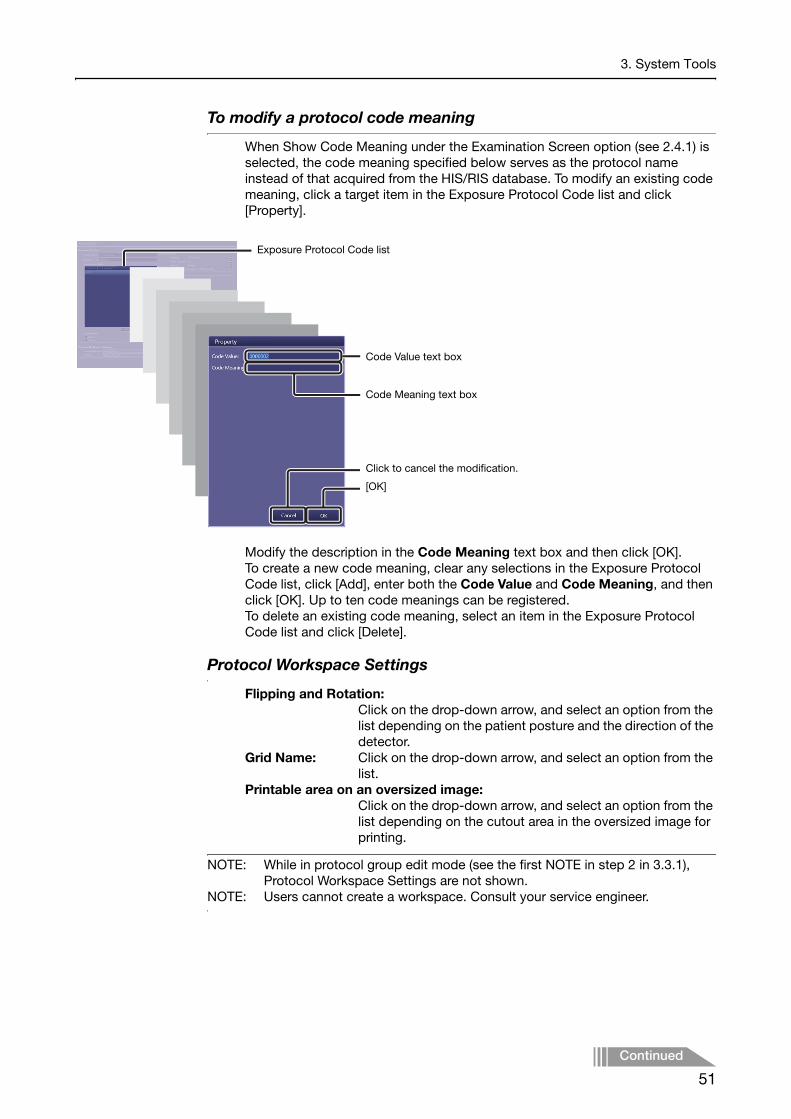
To modify a protocol code meaning
When Show Code Meaning under the Examination Screen option (see 2.4.1) is selected, the code meaning specified below serves as the protocol name instead of that acquired from the HIS/RIS database. To modify an existing code meaning, click a target item in the Exposure Protocol Code list and click [Property].
Modify the description in the Code Meaning text box and then click [OK].To create a new code meaning, clear any selections in the Exposure Protocol Code list, click [Add], enter both the Code Value and Code Meaning, and then click [OK]. Up to ten code meanings can be registered.To delete an existing code meaning, select an item in the Exposure Protocol Code list and click [Delete].
Protocol Workspace Settings
Flipping and Rotation:Click on the drop-down arrow, and select an option from the list depending on the patient posture and the direction of the detector.
Grid Name: Click on the drop-down arrow, and select an option from the list.
Printable area on an oversized image:Click on the drop-down arrow, and select an option from the list depending on the cutout area in the oversized image for printing.
NOTE: While in protocol group edit mode (see the first NOTE in step 2 in 3.3.1), Protocol Workspace Settings are not shown.
NOTE: Users cannot create a workspace. Consult your service engineer.
Exposure Protocol Code list
Code Value text box
Code Meaning text box
Click to cancel the modification.
[OK]
Continued
51

3. System Tools
To confirm the exposure summary of the X-ray generator
Click [Next] in the protocol property screen 1.
NOTE: If [Next] is not shown, click [Cancel] or [OK] to go back to the Protocol Editor screen, and then enter workspace edit mode (see step 2).
APR Editor
When the anatomical program (APR) is used for the communication with the X-ray generator, the exposure summary is displayed in the system status bar, and the following properties can be confirmed.Exposure type: Radiography refers to digital X-ray radiography.
Select Prolonged Exposure option to turn on the prolonged exposure feature.
Source object distance(SOD):Enter the distance between the X-ray tube and the patient.
Source imaging receptor distance(SID):Enter the distance between the X-ray tube and the detector.
APR ID: The IDs are specified for exposure summary.
3 Set the properties.
Click [OK] in the protocol property screen 1 or 2.
4 Exit the Protocol Editor.
Click [Exit] in the Protocol Editor screen.
[OK]
Click to return to the protocol property screen 1.
Protocol property screen 2
52

3. System Tools
3.3.2 Creating new protocols
A new protocol is created by editing an existing protocol. Be sure to select an existing protocol with appropriate parameter configurations to use in creating the new protocol.
1 Select an original protocol.
See step 1 in 3.3.1 for details on operation.
2 Duplicate the original protocol.
Click [Copy] while in protocol group edit mode (see the first NOTE in step 2 in 3.3.1).A copy protocol group appears below the original one. “Copy1” at the end of the copy protocol group name distinguishes the copy from the original.
3 Set the copy protocol to workspace edit mode.
Click the arrow for the copy protocol group, and then click the protocol.
4 Modify the copy protocol to create a new protocol.
See 3.3.1 for details on operation.
5 Arrange the new protocol in the protocol tray.
Click [Set]. [Set] changes to [Cancel] and available destinations indicated by blank rectangles appear in the protocol tray. Click the target destination.To cancel the arrangement, click [Cancel] before clicking the target destination.
[Copy]
Original protocol group in protocol group edit mode
[Set]/[Cancel]
[Edit]
Click to show and hide the protocols.
53

3. System Tools
3.3.3 Modifying the category tabs
The category tab controls the use of the protocol tray labeled with the tab. When the tab is disabled, the protocols categorized in the protocol tray are not available.
1 Select the target category tab.
Click a category tab.
2 Enable the target category tab.
Select the check box on the tab.To disable the tab, clear the check box.
3 Modify the name of the tab.
Click [Rename], modify the name in the Tab Name text box, and then click [OK] in the Rename Tab dialog box.
4 Change the order of the tab.
Click [Up] or [Down].
[Down]
Category tabs
[Rename]
[Up]
Click to scroll the category tabs.
54
3. System Tools
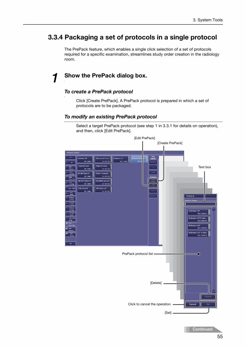
3.3.4 Packaging a set of protocols in a single protocol
The PrePack feature, which enables a single click selection of a set of protocols required for a specific examination, streamlines study order creation in the radiology room.
1 Show the PrePack dialog box.
To create a PrePack protocol
Click [Create PrePack]. A PrePack protocol is prepared in which a set of protocols are to be packaged.
To modify an existing PrePack protocol
Select a target PrePack protocol (see step 1 in 3.3.1 for details on operation), and then, click [Edit PrePack].
Text box
[Create PrePack]
[Edit PrePack]
[Set]
[Delete]
Click to cancel the operation.
PrePack protocol list
Continued
55

3. System Tools
2 Label the PrePack protocol.
Enter the name of the PrePack protocol in the Prepack Name text box.
3 Select target protocols from the protocol tray.
See step 1 in 3.3.1 for details on operation. Selections are added to the PrePack protocol list.
To remove a protocol from the PrePack protocol list
Select a target protocol from the list, and then click [Delete].
4 Arrange the PrePack protocol in the protocol tray.
Click [Set]. Available destinations indicated by blank rectangles appear in the protocol tray. Click the target destination.
NOTE: PrePack protocols can be moved to other trays as well as the current tray. In such cases, select the target tab before selecting the target destination.
3.3.5 Creating new protocol trays
A new protocol tray is created by editing a preset protocol tray with no protocol set.
1 Select a blank protocol tray.
Click [∨] on the Protocol Editor screen to scroll down the category tabs, and select a protocol tray with no protocol set.
Click to scroll the category tabs.
[Set]
Protocol
56

3. System Tools
2 Select a protocol.
Click the arrow for the Protocol group on the protocol list, and click the target protocol so that the selected protocol is highlighted in workspace edit mode (see step 2 in 3.3.1).
3 Arrange the protocol in the protocol tray.
Click [Set]. Available destinations indicated by blank rectangles appear in the protocol tray. Click the target destination.
4 Continue arranging protocols.
Repeat steps 2 and 3.
To add new protocols
See 3.3.2 for details on operation.
5 Modify the name of the category tab.
See 3.3.3 for details on operation.
To change the order of category tabs
See 3.3.3 for details on operation.
57

3. System Tools
3.4 QC Tool button
To assure the strict image quality required for medical imaging systems, calibration measures for the connected detector are provided for the Control Software.
NOTE: This tool require the Calibration Administrations privileges for operation (see step 2 in 2.2).
NOTE: Be sure to remove the grid from the detector before conducting the following steps.
CAUTIONBe sure to confirm that there is no person in the radiology room during Calibration and Performance Test to prevent the possibility of any persons exposing themselves to X-ray exposure.
58

3. System Tools
3.4.1 Calibrating the detectorA combined performance of a Calibration (for the detector correction data generation) and a Performance Test (for the detector inspection) that was conducted when the system was set up, is required regularly (approximately once a year). The steps for operation of both the Calibration and Performance Test are almost the same. First conduct the Calibration, and then the Performance Test for confirmation.
NOTE: Screens in Calibration mode are used for the following steps.
1 Enter calibration/performance test mode and select the target detector.
Click [Calibration] or [Performance Test], and then select a detector.
[Performance Test]
Available detectors
[Calibration]
Continued
59
3. System Tools
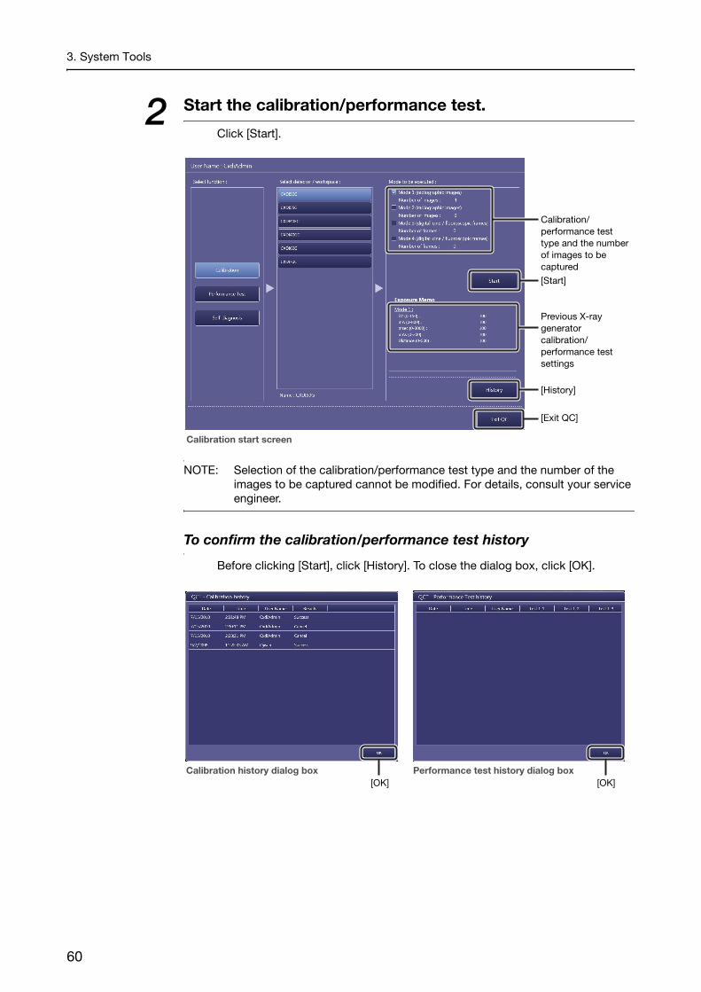
2 Start the calibration/performance test.
Click [Start].
NOTE: Selection of the calibration/performance test type and the number of the images to be captured cannot be modified. For details, consult your service engineer.
To confirm the calibration/performance test history
Before clicking [Start], click [History]. To close the dialog box, click [OK].
[History]
Calibration/performance test type and the number of images to be captured
[Exit QC]
Previous X-ray generator calibration/performance test settings
[Start]
Calibration start screen
[OK][OK]Calibration history dialog box Performance test history dialog box
60

3. System Tools
3 Start exposure.
Confirm that the indicator appears in the system status bar, and then press and hold the exposure switch of the X-ray generator.
To record the exposure conditions used for the current calibration
For further reference, enter the exposure conditions in the Exposure Memo.These text boxes are available when all the calibrations are complete.
Exposure switch
System status bar
Exposure Memo
Click to return to the calibration/performance test start screen.Current calibration/performance
test number/total number of calibrations/performance tests
[Next]/[End]/[Retry]
Check result list
Continued
61

3. System Tools
To automatically calculate the msec/mAs value in the Exposure Memo
After entering the mA (X-ray tube current) value, if one of the values for msec (exposure time) and mAs (current-time product) is entered, the other value will automatically be calculated. Select one of the Auto (calculation) check boxes for msec or mAs to enable the auto calculation feature.
When an error occurs during calibration
To confirm the details of a calibration result, click [Details] in the Check result list. After confirming the results, click [OK] to close the dialog box. Change the X-ray generator settings based on the results of the failed calibration, and then click [Retry].
4 Set the detector and X-ray generator to ready status.
Click [Next].
5 Repeat calibration/performance test.
Repeat steps 3 and 4 until all the calibrations/performance tests are complete.
6 Exit the QC Tool.
Click [Exit QC] in the calibration/performance test start screen.
3.4.2 Inspecting the detector (Performance Test)A Performance Test by itself can also be conducted to maintain the detector. In accordance with the medical site guidelines, the test should be performed on a regular basis. If problems are detected, perform calibration. See 3.4.1 for details on operation.
NOTE: Before conducting a performance test, be sure to adjust the X-ray generator settings based on the Exposure Memo data recorded during previous calibration.
NOTE: Be sure to inform your service engineer of the error code that appears during a performance test.
62

3. System Tools
3.4.3 Inspecting the detector/power box (Self-diagnosis)
The Control Software inspects the connected detector/power box using test pattern images and so on. This inspection is required to be conducted once a month.
NOTE: Be sure to inform your service engineer of the error code that appears during a self-diagnosis.
1 Enter Self-diagnosis mode and select the target workspace.
Click [Self-diagnosis], and then select a workspace.
Available workspaces
[Self-diagnosis]
The connection with the detector is incomplete, or thepower box is turned off.
Continued
63

3. System Tools
NOTE: A battery indicator and a signal strength indicator are shown on the workspace for wireless detectors.
The remaining battery charge is indicated as follows:
: 60–100% charge
: 9–59%
: 5–8%
: 4% or less
When the indication changes to or , a warning/error dialog box appears to prompt a battery recharge.
Signal strength is indicated as follows:
: Strong
: Medium
: Poor
: No signal
For the wireless detector, refer to the Digital Radiography CXDI series User’s Manual.
Signal strength indicator
Battery indicator
Example of Workspace Indicator for wireless detectors
64

3. System Tools
2 Start the self-diagnosis.
Click [Start]. The Control Software starts self-diagnosis, and the results appear in the Result list.
NOTE: Selection of the test type cannot be modified. For details, consult your service engineer.
To confirm the self-diagnosis history
Before clicking [Start], click [History]. To close the dialog box, click [OK].
3 Exit the QC Tool.
Click [Exit QC] in the Self-diagnosis start screen.
[History]
Test type
[Exit QC]
[Start]
Result list
Self-diagnosis start screen
[OK]
65

3. System Tools
3.5 Image Proc buttonImage processing parameters included in the protocol can be modified while simulating the processing parameter settings using the sample image that was previously captured.
NOTE: Operations for this tool require the ImageProcessing Administrations privileges (see step 2 in 2.2).
1 Select the target protocols in the protocol tray.
Click the target tab and then click a protocol from the protocol tray.The selected protocol is highlighted. Click [Edit Radiography] to show the sample image selection screen.
Protocol tray
[Edit Radiography]
Click to scroll the category tabs.
Category tabs
[Exit]
Protocol selection screen
66
3. System Tools
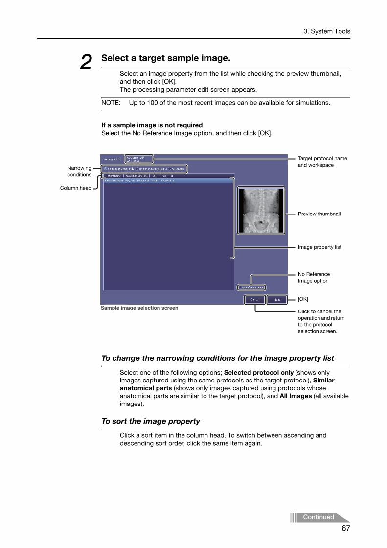
2 Select a target sample image.
Select an image property from the list while checking the preview thumbnail, and then click [OK].The processing parameter edit screen appears.
NOTE: Up to 100 of the most recent images can be available for simulations.
If a sample image is not requiredSelect the No Reference Image option, and then click [OK].
To change the narrowing conditions for the image property list
Select one of the following options; Selected protocol only (shows only images captured using the same protocols as the target protocol), Similar anatomical parts (shows only images captured using protocols whose anatomical parts are similar to the target protocol), and All Images (all available images).
To sort the image property
Click a sort item in the column head. To switch between ascending and descending sort order, click the same item again.
Target protocol name and workspace
Sample image selection screen
Column head
No Reference Image option
[OK]
Preview thumbnail
Image property list
Narrowingconditions
Click to cancel the operation and return to the protocol selection screen.
Continued
67

3. System Tools
3 Modify the image processing parameters.
Refer to 6.2, and 7.3 in the Operation Manual for details on operation.
To set the EIt value
Enter a value in the EIt text box referring to the current EI value. If the text box is left blank, DI cannot be calculated.
NOTE: The values of EI, EIt, and DI can be embedded on both the preview screen and film sheet images. See 2.5.1 for details on operation.
EI (Exposure Index)EI is an approximative indicator of the dose that reaches the detector, as calculated per IEC 62494-1 standards from the captured images.Under the same exposure conditions, the indicator and the dose are proportional.Depending on the exposure conditions, the indicator may vary on a 10 percent basis up to several 100 percent larger. For details, refer to IEC 62494-1.
EIt (Target Exposure Index)EIt is the target EI level. Set the appropriate EIt using EI obtained from previous captured radiographic images as feedback.
DI (Deviation Index)DI is a logarithmic index indicating the difference between the EI and EIt. When the EI value is the same as EIt, the DI is calculated as 0. The bigger the difference between EI and EIt, the larger the DI absolute value becomes. A positive DI value is calculated when EI is bigger than EIt, and a negative value is calculated when EI is smaller than EIt.
Toolbar
EIt text box
[OK]
Click to cancel the operation and return to the protocol selection screen.
EI value
Image Processing dialog box
Click to cancel the operation and return to the sample image selection screen.
(Output settings)
Processing parameter edit screen
(Arrangement)
68

3. System Tools
NOTE: The result of the Grid Suppression control is not reflected in the preview image. However, the result can be confirmed solely in the printed image. If required, proceed to step 4.
NOTE: The result of the Peripheral Mask control is not reflected in the preview image. However, the Peripheral Mask result can be confirmed in the [EXAM > Examination] or [PAST > View] screen. Refer to Chapter 5 in the Operation Manual.
4 Transmit the resulting image, if required.
Click , select the destination, and then click [Send Image].Refer to 7.2 in the Operation Manual for details on operation.
Saving or printing the resulting images for strict image evaluationTo evaluate the resulting image quality, it is recommended to check the images on the DICOM viewer or on printed film sheet. In such cases, the Patient ID and Series Description options are provided in the Output Settings dialog box. For example, enter a title that indicates that the image is not for examination in the Patient ID text box, and also enter a summary of the parameter modifications in the Series Description text box.
Patient ID text box
Series Description text box
[Send Image]
Click to cancel the operation.
Continued
69

3. System Tools
When the image arrangement screen appears
Refer to “7.1.1 Arranging images automatically” in the Operation Manual.
5 Set image processing parameter.
Click [OK] in the processing parameter edit screen.
6 Exit image processing parameter edit mode.
Click [Exit] in the protocol selection screen.
70

3. System Tools
3.6 DB Backup buttonOn the Backup screen, all of the Control Software databases or specific examination information can be manually backed up to a preset destination directory. Be sure to back up the database before performing any major modification of the Control Software.
NOTE: Users cannot change the destination directories for both options. For details, consult your service engineer.
To exit backup mode
Click [Exit].
3.6.1 Database Backup option
1 Perform backup for all of the Control Software databases.
Click [Execution] for this option.
Destination directory for the Control Software databases
Destination directory for the examination information
[Exit]
71

3. System Tools
3.6.2 Output Exam Log option
The following information can be backed up in a CSV format file: Image capture date, image capture time, accession number, exposure mode, protocol name, body part, patient orientation, operator name, image rejection date, image rejection time, reason for image rejection, and name of operator who rejected the image.
1 Specify target examinations by period of time.
Enter the year, month, and date for both the Start Date and End Date option.
NOTE: When the Start Date and End Date are not specified, log data of all examinations are output.
2 Perform backup for the examination information.
Click [Execution] for this option.
72

Appendix
1 Imaging Parameters
2 Saving Imaging Parameters
3 Details of Imaging Parameters
4 Adjustment Procedure
5 Technical Overview of Image Processing
6 Printing IP Parameter Values on printed images
7 Monitor Gamma Adjustment

Appendix
IntroductionThis appendix gives instructions for user adjustment to imaging parameters for captured images from Canon digital radiography system CXDI series and CXDI Control Software NE (hereafter “the control software”) systems. For details on operating procedure, refer to the chapter 1 thru 3 of this Setup Guide and the separate Operation Manual. The control software includes image processing functions to produce optimal images. Site-specific adjustments are made during installation by service engineers.For questions or technical issues when using imaging parameters to adjust captured images, contact your service engineer.
NOTE: Before adjusting imaging parameters, calibrate the output devices, such as local preview monitors, PACS, HD DICOM monitors, and film printers, to ensure consistent image appearance. Insufficient calibration will make adjustment of interrelated imaging parameters complex and prevent optimal image quality from being obtained easily.
NOTE: If you find undesirable artifacts on adjusted images or realize any loss of details necessary for diagnosis, attenuate the effect of adjustments or cancel them. Be sure to check that the adjusted images are acceptable.
74

Appendix
1 Imaging Parameters
1.1 Overview of Imaging ParametersThe control software incorporates a variety of image processing to enable consistently optimal imaging.Settings have already been configured to leverage this processing for optimal rendering (in each study, each anatomical part, and each patient). It is also possible to fine-tune imaging by altering the intensity or level of processing through customization of imaging parameters.
1.2 Classification of Imaging ParametersImaging parameters are classified into three levels (1–3).
Level 1: General imaging parameters that are occasionally applied to specific patients.Level 2: Imaging parameters that are rarely applied to specific patients.In general, there is no need to adjust these parameters.Level 3: Global parameters, not restricted to specific patients.
1.3 Access PrivilegesWhether or not users can access imaging parameters depends on two levels of authorization, based on their image processing privileges. In this appendix, users authorized for advanced adjustment of image processing parameters are called imaging administrators. Users without this authorization are simply called regular users.
Regular users:Users who can edit level 1 parameters.Imaging administrators:Administrators who can edit all parameters (levels 1–3).
However, regular user privileges (for level 1 image adjustment) are sufficient in most workflows. When regular users attempt to access level 2 or 3 image adjustment parameters, the Authorization dialog box is displayed indicating insufficient privileges.
When the Authorization dialog box is displayedEntering the login name and password of a user with higher-level authorization in this dialog box grants provisional access to level 2 and 3 parameters.This provisional access is valid only until the current study is finished. After the current study, even if users attempt to access level 2 or 3 parameters for multiple studies of the same patient, the login name and password of an imaging administrator is required.
75

Appendix
1.4 How to Access Imaging ParametersTo access level 2 parameters, click indicator 2 in the access level selector/indicator in the Image Processing pane. To access level 3 parameters, when level 2 parameters are displayed, click indicator 3 in the access level selector/indicator.
Access level selector/indicators
76

Appendix
2 Saving Imaging ParametersThis chapter gives overview of saving imaging parameters. Parameters are saved per-protocol basis* and per-study basis.The categories, parameters (functions), and levels of image adjustment are as follows. The table also indicates whether adjusted parameters can be saved as the default parameters. See also 2.1 Adjustment and Saving of Default Parameters.* Default (per-protocol basis) parameters are automatically applied to the captured
images as default setting.
*1 Only when REX is selected for Brightness Adjustment*2 Only when Auto is selected for Brightness Adjustment
Category ParameterLevel Can be
Saved as Defaults1 2 3
Generals
Rotate Clockwise Yes
Rotate Counterclockwise Yes
Flip Horizontal Yes
Flip Vertical Yes
AnalysisDynamic Range No
ROI No
Anatomical Part
Category Yes
Anatomical Part Yes
Direction Yes
LUT
Curve Shape Yes
Brightness Adjustment Yes
REX*1 Yes
Base Brightness*2 Yes
Base Contrast Yes
Brightness No
Contrast No
Enhancement
Edge Enhancement Yes
Edge Frequency Yes
Contrast Boost Yes
Dynamic Range Adjustment
Dark Region Yes
Bright Region Yes
Noise Reduction Effect Yes
Grid SuppressionGrid Suppression Yes
Grid Name Yes
Peripheral Mask Mask Yes
77

Appendix
2.1 Adjustment and Saving of Default Parameters
2.1.1 AdjustmentAmong default imaging parameters, level 3 parameters are global and not restricted to specific patients. When configuring these parameters, use values that represent the optimal average values across multiple subjects. The adjustment procedure is described in the next chapter.
Interfaces enabling editing of default parameters
When adjusting settings on the Image Processing Adjustment screen, also see Chapter 3.5 of this Setup Guide.
2.1.2 SavingDefault parameters can be saved on a per-protocol basis. These parameters can be edited in the above three interfaces, but saving requires imaging administrator privileges. Default parameters cannot be saved with regular user privileges.
2.2 Adjustment and Saving of Study Parameters
2.2.1 AdjustmentEssentially, adjustment is only possible for level 1 imaging parameters. However, if additional fine-tuning is desired, adjust level 2 imaging parameters. Adjustment of level 3 imaging parameters is not necessary. The adjustment procedure is described in the next chapter.
Interfaces enabling editing of study parameters
2.2.2 SavingStudy parameters can be saved, as needed. These parameters can be edited in the above two interfaces and be saved with regular user privileges. The same applies to users with imaging administrator privileges.
Interface Adjustment Scenario Notes
Image Proc button
Adjustment after specifying a protocol
The protocol name must be known in advance.
EXAM tab Adjustment during a studyParameters are saved during level 3 adjustment by clicking [Save As Default].
PAST tab Adjustment after selecting a patient who has already been imaged
Interface Adjustment Scenario Notes
EXAM tab Adjustment immediately after image capture
-
PAST tab Adjustment after a study is finished
-
78

Appendix
3 Details of Imaging ParametersThis chapter gives explanations of each parameter function and operating procedures for these parameters.
NOTE: If you find undesirable artifacts on adjusted images or realize any loss of details necessary for diagnosis, attenuate the effect of adjustments or cancel them. Be sure to check that the adjusted images are acceptable.
NOTE: To confirm the results of effects in the imaging parameters, check images after transfer to storage or output to film.
3.1 Main ParametersThe number of parameters varies depending on the Brightness Adjustment setting. Two Brightness Adjustment settings are available: Auto and REX.
NOTE: Auto: Mode for automatic tone curve adjustment, for uniform brightness in the region of examination regardless of X-ray dose
REX: Mode for tone curve adjustment to change brightness of the region of examination based on X-ray dose
Top Screen of Image Processing Pane*
* This pane appears in [EXAM > Examination] and [Past > View] screens.
Auto Mode
REX Mode
Click a category to access image adjustment parameters based on user privileges.
1)
2-A)
3)
4)
5)
6)
7)
1)
2-B)
6)
7)
79

Appendix
3.2 Description of Parameters
1) Anatomical PartFunctions for automatic adjustment of image tone after exposure. Complete the Anatomical Part and Direction settings according to study objectives and the anatomical part involved. For example, specify Chest in Anatomical Part for automatic tone adjustment after exposure suited to chest diagnosis.
Category and Anatomical PartThe anatomical parts are categorized as follows.
Category Anatomical Part
Contrast-Medium
Upper Gastrointestinal
Lower Gastrointestinal
Hepato Billiary Pancreatic
Urinary
Myelo
Skull
Skull
Ear
Nose Sinus
Nose
Mandible
Chest/Abdomen
Chest
Child Chest
Infant Chest
Abdomen
Spine
Cervical Spine
Thoracic Spine
Lumbar Spine
Rib Cage
Clavicle
Shoulder
Scapula
Rib
Sternum
80

Appendix
* Only for stitch protocol
DirectionImaging directions (orientations) are as follows.
FrontLateralOther
Pelvis
Pelvis
Sacrum
Ilium
Coccyx
Pubis
Upper-Extremity
Humerus
Elbow
Forearm
Wrist
Hand
Lower-Extremity
Hip Joint
Femur
Knee
Leg
Ankle
Foot
Other Unknown
Stitch*
Whole Spine
Full leg
Unknown
Category Anatomical Part
Continued
81

Appendix
2-A) LUT (Auto mode)Adjusts tone curve parameters.
Curve ShapeSpecify the tone curve. Select one of the following four tone curves.
SA: S-shaped tone curve equivalent to standard radiographic film.SB: S-shaped tone curve with higher contrast in bright regions.SC: S-shaped tone curve with higher contrast in dark regions.LN: Uniform contrast throughout all brightnesses.
Brightness AdjustmentSelect Auto.In Auto mode, the tone curve will automatically be adjusted so that the brightness of the overall examination region of all images wil be almost the same regardless of the X-ray dose.
Base Brightness (1 to 29)Specify the standard brightness.Set the value higher for brighter images. Conversely, set it lower for darker images.Choose values that represent optimal average values across multiple subjects.
Base Contrast (1 to 29)Specify the standard contrast.Set the value higher for more overall contrast. Conversely, set it lower for less contrast overall.Choose values that represent optimal average values across multiple subjects.
Brightness (-10 to +10)Used to fine-tune brightness. Adjust the brightness in a range of -10 to +10 relative to the Base Brightness value.Set the value higher for brighter images. Conversely, set it lower for darker images.The supported adjustment range depends on the Base Brightness value. In some cases, the range may be narrower than -10 to +10.
Contrast (-10 to +10)Used to fine-tune contrast. Adjust the contrast in a range of -10 to +10 relative to the Base Contrast value.Set the value higher for more overall contrast. Conversely, set it lower for less contrast overall.The supported adjustment range depends on the Base Contrast value. In some cases, the range may be narrower than -10 to +10.
82

Appendix
2-B) LUT (REX mode)Adjusts tone curve parameters.
NOTE: REX mode is used for manual studies (when the X-ray dose was intentionally controlled to achieve a specific image brightness) or in follow-up exams when imaging is based on film density*¹, for example.*¹ Or on brightness, in display-based diagnosis.
Curve ShapeSee 2-A) LUT (Auto mode).
Brightness AdjustmentSelect REX.In REX mode, the brightness of the overall examination region of an image varies depending on the X-ray dose (images are darker at higher X-ray doses and brighter at lower doses).
REX (0 to 65535)Specify the standard brightness in REX mode.Set the value higher for brighter images. Conversely, set it lower for darker images.
NOTE: The REX (Reached Exposure Index) value is equivalent to that of the output from the image sensor pixels that are included in a region, where the referential density of 0.75D is applied, in a diagnostic image captured using the CXDI system.If the applied imaging parameters are the same in Auto mode, the REX value varies depending on the X-ray dose that reaches the image sensor, and provides an indication of the X-ray dose radiated from the generator.
Base Contrast (1 to 29)See 2-A) LUT (Auto mode).
Brightness (-10 to +5)Used to fine-tune brightness. Adjust the brightness in a range of –10 to +5 relative to the Base Brightness.Set the value higher for brighter images. Conversely, set it lower for darker images.
Contrast (-10 to +10)See 2-A) LUT (Auto mode).
Continued
83

Appendix
3) Enhancement
Adjusts image enhancement parameters.
Select the check box to activate enhancement. The following three parameters are available.
Edge Enhancement (0 to 20)Set the value higher to emphasize image edges, making images sharper.
Edge Frequency (1 to 7)Adjust the frequency range for edge enhancement.Set the value lower for edge enhancement in low-frequency regions. This is suitable for large structures such as organs and bones.Set the value higher for edge enhancement in high-frequency regions. This is suitable when imaging blood vessels, trabecular bones, or other small structures.
Contrast Boost (0 to 20)Set the value higher to enhance local contrast. This increases sharpness in thicker areas of the body, as in trunk imaging.
4) Dynamic Range AdjustmentAdjusts the dynamic range adjustment parameters.
Select the Dark Region check box to activate dynamic range adjustment of dark regions. Conversely, select Bright Region to activate dynamic range adjustment of bright regions.
Dark Region (1 to 20)Set the value higher to brighten dark image areas. If dark image areas are too dark, increase the value. If they are too bright, decrease the value.
Bright Region (1 to 20)Set the value higher to darken bright image areas. If bright image areas are too bright, use a large value. If they are too dark, use a low value.
84

Appendix
5) Noise Reduction (1 to 10)Reduces graininess in image areas of low X-ray exposure.
Select the check box to activate noise reduction. Set the value higher to reduce graininess. However, images will be somewhat less sharp.
6) Grid Suppression (On/Off)Reduces the appearance of grid lines in captured images.
When this check box is selected, grid suppression is applied to images at the time of transfer to storage or film output. If a grid other than the one set at the parameter configuration is used, select the check box to activate grid suppression, and then the name of the grid that is attached.
NOTE: In order to check the effect of this image processing, examine images transferred to storage or output to film. Results of grid suppression cannot be seen in images as displayed.
7) Peripheral Mask (On/Off)Peripheral masking is a function to conceal areas outside the region of examination.
When this check box is selected, [Mask] is displayed in the toolbar and the masking appears. Refer to 6.1.5 in the separate Operation Manual.
NOTE: The masking is not applied to images shown in the preview image on the processing parameter edit screen during modification of a protocol (see 3.5 in this Setup Guide). Masking is translucent on EXAM and PAST screens. At the time of output, an opaque black mask conceals peripheral images.
85

Appendix
3.3 Other Parameters
Dynamic RangeIn the figure, the subject’s dynamic range is bounded by Shadow/Highlight adjustment sliders. However, because the optimal dynamic range is normally set after automatic analysis, avoid moving the sliders.
Determining if the Dynamic Range is SuitableExamine both the image preview and the histogram to determine suitability. Determine the exact histogram range that corresponds to the subject’s dynamic range. This range does not include peripheral areas, metal objects, or blank, transparent areas. Accurate judgment requires some experience. For function details, see 5.2.3 Dynamic Range Analysis and 5.3.2 Dynamic Range Adjustment in this appendix.
ROIFor specifying the region of interest. If there are overexposed highlights or underexposed shadows, click this button and specify the ROI.
Histogram
Shadow adjustment slider
Highlight adjustment slider
86

Appendix
4 Adjustment ProcedureThis chapter gives instructions for adjusting exposure images through various parameters. Before adjusting imaging parameters, calibrate the output devices, such as local preview monitors, PACS, HD DICOM monitors, and film printers, to ensure consistent image appearance. Insufficient calibration will make adjustment of interrelated imaging parameters complex and prevent optimal image quality from being obtained easily.
NOTE: If you find undesirable artifacts on adjusted images or realize any loss of details necessary for diagnosis, attenuate the effect of adjustments or cancel them. Be sure to check that the adjusted images are acceptable.
4.1 Default ParametersFor image adjustment involving default parameters, perform adjustment on multiple exposure images of various physiques and specify the average values as default parameters.The process first involves refinement of the overall/bright area/dark area image appearance by adjusting the tone curve and dynamic range, followed by refinement of image details by adjusting noise reduction and image enhancement.Figure 4.1 presents a flowchart of the procedure for adjusting default parameters. Table 4.1 describes each step in this process.
Continued
87

Appendix
Figure 4.1. Flowchart of the Adjustment Procedure for Default Parameters
1) Select an image for adjustment
2) Deactivate Enhancement, Dynamic Range Adjustment, and Noise Reduction.
3) Set the LUT/tone curve: LUT > Curve Shape
4) Adjust ROI brightness: LUT > Base Brightness
5) Adjust ROI contrast: LUT > Base Contrast
If dark regions are too dark
If bright regions are too bright
6) Adjust dark regions: Dynamic Range Adjustment > Dark Region
7) Adjust bright regions: Dynamic Range Adjustment > Bright Region
If the brightness of dark or bright regions is still unacceptable
If there is undesirable graininess
8) Adjust noise reduction: Noise Reduction > Effect
If images are blurry
9) Set the edge frequency for enhancement: Enhancement > Edge Frequency
10) Adjust sharpness: Enhancement > Edge Enhancement
If local contrast is insufficient
11) Adjust local contrast: Enhancement > Contrast Boost
START
END
88

Appendix
Table 4.1. Flowchart Description for Default Parameters
No. Description
1)Select images for parameter adjustment.At this time, avoid images for which automatic analysis failed.
2)Deactivate image enhancement, dynamic range adjustment, and noise reduction.
3) to 5)
Adjust tone curve parameters (curve shape, base brightness, and base contrast).At this time, adjust the settings for optimal ROI brightness and local contrast. Note that you can specify a high value in the base contrast parameter, even if this causes underexposed shadows in dark areas and overexposed highlights in bright areas. You can correct this later by adjusting the dynamic range.
6)If dark areas are too dark compared to the brightness of the ROI, activate dark region control and adjust the value.
7)Similarly, if bright areas are too bright compared to the brightness of the ROI, activate bright region control and adjust the value.
5) to 7)
If the base contrast parameter is set too high relative to the image’s dynamic range, steps 6) and 7) may not be effective in achieving optimal brightness in dark and bright areas. In this case, set the base contrast parameter lower and repeat steps 6) and 7). If the base contrast parameter is set low, local contrast of the ROI will be low, but you can correct local contrast later in the enhancement parameter.
8)
Check image areas of low X-ray exposure. If there is undesirable graininess, activate noise reduction and adjust the value. Note that it may be difficult to verify effect processing on local computers used for previewing images. Refer to a printed film image or HD DICOM monitor to verify effect processing as you adjust the parameters.
9) and 10)
Check image sharpness. If images are blurry, activate enhancement and edge frequency and adjust the value. Note that it may be difficult to verify effect processing on local computers used for previewing images. Refer to a printed film image or HD DICOM monitor to verify effect processing as you adjust the parameters.
11)Check the local contrast of images. If contrast is too low, activate contrast boost and adjust the value.
89

Appendix
4.2 Study ParametersImage quality is automatically optimized to account for individual variation in X-ray dose, physique, and other factors. For this reason, no fine-tuning of parameters is generally necessary. However, the effect of tone curve and dynamic range adjustment will be inconsistent if automatic analysis fails, and in this case, the parameters must be fine-tuned.
NOTE: Enhancement and noise reduction parameters, on the other hand, need not be adjusted after default parameters are determined because the results of automatic analysis are not applicable to this image processing.
Figure 4.2 presents a flowchart of the procedure for fine-tuning study parameters. This procedure involves changing tone curves and dynamic range to adjust the brightness. Table 4.2 describes each step in this process.
Figure 4.2. Flowchart of Adjustment Procedure for Study Parameters
If ROI brightness differs greatly from base brightness
1) Adjust ROI brightness: [ROI] of the toolbar
To fine-tune ROI brightness
To adjust ROI contrast
To adjust brightness of dark regions
To adjust brightness of bright regions
2) Adjust ROI brightness: LUT > Brightness
3) Adjust ROI contrast: LUT > Contrast
4) Adjust dark regions: Dynamic Range Adjustment > Dark Region
5) Adjust bright regions: Dynamic Range Adjustment > Bright Region
START
END
90

Appendix
Table 4.2. Adjustment Flowchart Description for Study Parameters
No. Description
1)Automatic analysis may fail if the ROI brightness differs significantly from the base brightness, or if there are overexposed highlights or underexposed shadows. Adjust the ROI image manually to make sure it is suitable.
2)To fine-tune ROI brightness, adjust the brightness parameter of tone curves. Correct inconsistent automatic analysis of patients, and fine-tune ROI adjustment results as needed.
3)To change local contrast in the ROI, adjust the contrast parameter of tone curves.
4)If dark areas are too dark relative to ROI brightness, use a higher value for dark region control. If areas are too bright, on the other hand, reduce the value.
5)If bright areas are too bright relative to ROI brightness, use a higher value for bright region control. If areas are too dark, on the other hand, reduce the value.
91

Appendix
5 Technical Overview of Image ProcessingThis chapter presents a technical overview for users of image processing by the control software.
5.1 Overview of Image ProcessingImage processing by the control software can be broadly classified into three stages of image processing: pre-processing, automatic analysis, and processing images for use in diagnosis as shown in Figure 5.1. In each case, after conversion to digital signals, image from the FPD (at this point, the images are referred to as “raw image.”*¹) is pre-processed for uniformity. After pre-processing (at which point images are referred to as “pre-processed image”), automatic analysis is conducted to determine image features or characteristics. This is followed by processing to prepare images suitable for diagnosis. At this stage of image processing, multiple imaging parameters*² can be adjusted interactively to provide diagnosis images tailored to a variety of requirements. Also at this stage, the results of analysis are applied in optimal image processing for the X-ray dose and patient physique involved.
*¹ Raw images produced by the LANMIT system are irrelevant to end users.*² Details on configurable parameters are given in 3 Details of Imaging Parameters.
Figure 5.1. Image Processing Sequence
Raw Image(Images from the FPD )
Pre-processed Image
Diagnosis Image
Image Display Device
Storage
Pre-processing
Automatic Analysis
Image Processing for Diagnosis
92

Appendix
5.2 Automatic AnalysisImages produced by the digital radiography system CXDI series and control software have a wide dynamic range (extending to about four digits). For this reason, automatic analysis must be conducted to determine which part of the dynamic range will be useful in diagnosis and adjust the density (brightness) accordingly to prepare effective images for diagnosis. Automatic analysis must also detect what image areas were exposed to X-rays, because the area of exposure varies by study. Another role of the control software in automatic analysis is to calculate the Reached Exposure index and analyze a variety of image characteristics in other ways. This section describes the typical process of automatic analysis.
5.2.1 Detection of Irradiated FieldsAlthough the CXDI detector has a large effective area, the actual exposure area may be limited to an area smaller than this, depending on the study. The area is therefore detected automatically, by isolating the irradiated field. A schematic diagram of detection is shown in Figure 5.2. To detect this area, original, pre-processed images are analyzed to extract the edges of the irradiated field from multiple edge components in the image based on position, intensity, and other criteria. The area bounded by these edges is determined to be the area of exposure. Although this technique enables accurate detection of irradiated fields even when X-rays strike the detector at an angle, it cannot be used to detect multiple exposure areas.
Figure 5.2. Schematic diagram of detection of irradiated fields
Operators can save time in imaging setup and improve throughput by using the area detected as the initial value in cropping and peripheral masking (which masks areas outside the field).If detection fails, the area for cropping and peripheral masking must be set manually. For details on cropping and peripheral masking, refer to 6.1.4 and 6.1.5 in the separate Operation Manual.
Source Image Edges Extracted Edges of Exposure Area Extracted
Cropped
Masked
93

Appendix
5.2.2 Image Feature AnalysisGenerally consistent density (brightness) in the region of interest (ROI) is maintained for all subjects and X-ray doses by the control software through tone conversion*3. This processing requires a representative pixel value (the “reference pixel value”) of the ROI to be determined from captured images. The reference pixel value is calculated automatically through image feature analysis. A schematic diagram of analysis is shown in Figure 5.3 and Figure 5.4. Because the reference pixel value sought varies depending on the anatomical part studied, anatomically specific algorithms are used for image feature analysis. Analysis accuracy is enhanced through various means. For example, after the ROI is determined directly from irradiated image areas, the average ROI value is used as the reference pixel value (as shown in Figure 5.3). Alternatively, the ROI is determined from a histogram of irradiated image areas and its center of mass is used as the reference pixel value (as shown in Figure 5.4). Both methods are also used together.*³ Tone conversion is described in greater detail in 5.3.1 Image Tone Transformation.
*³ If analysis fails, the ROI must be set manually. For instructions on manual configuration, refer to 6.1.3 in the separate Operation Manual.
Figure 5.3. Schematic diagram of image-based image feature analysis
Figure 5.4. Schematic diagram of histogram-based image feature analysis
Source ImageImage Feature Analysis
ROI
ROI Average Output
Source Image
Image Feature Analysis
ROI Center of Mass
Histogram Output
ROI
Pixel Value
94

Appendix
5.2.3 Dynamic Range AnalysisTo enable dynamic range adjustment, the control software uses the subject’s dynamic range as the density (brightness) range in settings, regardless of subject physique. This processing requires an understanding of how the available dynamic range corresponds to the specific dynamic range of the subject (that is, what part of the dynamic range should be used for the subject). This part is calculated automatically through dynamic range analysis. A schematic diagram of analysis is shown in Figure 5.5. Analysis involves extracting the region that remains after areas other than the subject (such as X-ray shielding or areas of direct exposure on the FPD) are subtracted from the irradiated field. The range between minimum and maximum values in this area is then calculated*4, which represents the dynamic range of the subject. Dynamic range adjustment is described in greater detail in 5.3.2 Dynamic Range Adjustment.
*4 If analysis fails, the subject’s dynamic range must be set manually by referring a histogram. For details, refer to Dynamic Range in 3.3. Other Parameters in this appendix and 6.2.1 in the separate Operation Manual.
Figure 5.5. Schematic diagram of dynamic range analysis
Dynamic Range of Pre-processed Image
Dynamic Range of Subject
Source Image Dynamic Range Analysis
Minimum Value of Subject
Maximum Value of Subject
Pixel Value
Pixel Value
Histogram Histogram
Output
95

Appendix
5.3 Image Processing for DiagnosisPre-processed images are not always sufficient for use in diagnosis. For this reason, they must be converted to suitable images. Some parameters to prepare images for diagnosis can be adjusted in the control software. This section describes typical image processing in preparation for diagnosis.
5.3.1 Image Tone TransformationImages produced by the digital radiography system CXDI series and control software have a wide dynamic range (extending to about four digits). For this reason, to prepare images suitable for diagnosis, the part of the dynamic range that will be useful in diagnosis must be determined and suitable shading assigned. Additionally, because conventionally produced images are standard in diagnosis, image shading must also match that of conventional images. This processing is referred to as tone transformation. Figure 5.6 shows a relevant schematic diagram.
Figure 5.6. Schematic diagram of image tone transformation
In logarithmically transformed pre-processed image, representing higher or lower X-ray doses can be done simply by shifting the tone curve laterally. Thus, as shown in Figure 5.6, tone curves are shifted laterally depending on the dose so that the reference pixel value is at the desired density (brightness). As mentioned in the context of image feature analysis, the reference pixel value is calculated from the same, region-specific ROI regardless of the subject or dose. In this way, image tone transformation automatically adjusts the ROI to the desired density (brightness) regardless of the subject or dose. Moreover, because tone curves resembling the characteristic curves of conventional systems are used, this system provides diagnosis images equivalent to conventional images.
X-ray Dose (Source Pixel Value)
Source Image(Low X-ray Dose)
Reference Pixel Value Reference Pixel Value
Source Image(High X-ray Dose)
Resulting Image
Darker
Den
sity
(Brig
htne
ss)
Tone Curve Tone Curve
Shifted
Higher
96

Appendix
5.3.2 Dynamic Range AdjustmentAs described, image tone transformation yields diagnosis images equivalent to conventional images, regardless of the subject or dose. However, with this processing alone, it is difficult to represent the entire subject while maintaining sufficient contrast. This is due to the subject’s wide dynamic range, particularly in regions where subject depth varies significantly. For this reason, the entire subject is represented while maintaining sufficient contrast through dynamic range adjustment. Specifically, as shown in Figure 5.7, tone curves established in image tone transformation (“reference tone curves”) are adjusted to keep the subject’s dynamic range within the desired range of visibility. This adjustment of reference tone curves maintains visibility even in regions of the subject that would normally be affected by overexposed highlights or underexposed shadows. The adjustment also maintains the correlation between reference pixel values and desired density (brightness) and maintains tone curve gradients around reference pixel values. Thus, the subject’s dynamic range can be kept within the desired range of visibility without changing the density (brightness) or local contrast (difference between the local contrast of structures) of the ROI. Because the subject’s dynamic range is calculated automatically through dynamic range analysis, reference tone curves are also adjusted automatically to suit the subject’s dynamic range.
Figure 5.7. Tone curve adjustment
However, merely adjusting tone curves this way causes low local contrast where the tone curve gradient is slight, as in the profile signals shown in Figure 5.8, which obscures these structures. For this reason, the dynamic range adjustment performed compensates for local contrast, keeping the subject's dynamic range within the range of visibility without reducing local contrast of main structures in the subject, as shown in Figure 5.9.
X-ray Dose (Source Pixel Value)
Reference Tone Curve
Adjusted Tone Curve
Histogram
Reference Pixel Value
Dynamic Range of Subject
Density (Brightness)
Vis
ible
Ran
ge
Continued
97

Appendix
Figure 5.8. Alteration of local contrast
Figure 5.9. Compensation for local contrast
Figure 5.10 shows a schematic diagram of dynamic range adjustment. As mentioned, this adjustment compensates for local contrast relative to images after tone transformation. Local contrast compensation is performed by adding tone-transformed images to images resulting from compensation for local contrast, which are created by extracting main structural components in each frequency band from images produced by breaking down source images into multiple frequency bands.
Figure 5.10. Schematic diagram of dynamic range adjustment
Image Tone Transformation
Pixel Value
Local Contrast
Position
Pixel Value
Position
Vis
ible
Ran
ge
Pixel Value
Local Contrast
Position
Pixel Value
Position
Vis
ible
Ran
ge
Image Tone Transformation
Source Image Tone-Transformed Image Resulting Image
Image after Local Contrast Compensation
98

Appendix
5.3.3 Image EnhancementA variety of factors including X-ray and light scattering may cause blurriness in the raw image actually captured. Blurry images are made clearer and easier to see through image enhancement. A schematic diagram of enhancement is shown in Figure 5.11. After source images are broken down into multiple frequency bands, enhanced images are produced by extracting structures for enhancement in each frequency band. Image enhancement is then performed by adding enhanced images to source images.
Figure 5.11. Schematic diagram of image enhancement
In enhancement, edges and local contrast are emphasized by changing the structures subject to enhancement. To enhance edges, the edges of the structures are emphasized by generating overshoot and undershoot along edges, as is shown in Figure 5.12. Local contrast is enhanced by amplifying local differences between structures, as shown in Figure 5.13.
Figure 5.12. Schematic diagram of edge enhancement
Resulting ImageSource Image
Enhanced Image
Enhancement (Edge)
Pixel Value
Position
Pixel Value
Position
Overshoot
Undershoot
Continued
99

Appendix
Figure 5.13. Schematic diagram of local contrast enhancement
5.3.4 Noise ReductionThe raw image captured may also be affected by system noise, X-ray quantum noise, and various other types of noise superimposed onto the images. In this case, noise and image graininess is reduced through noise reduction. A schematic diagram of noise reduction is shown in Figure 5.14. Here, a noise image is created by extracting the noise superimposed in each frequency band from images obtained by breaking down source images into multiple frequency bands. The noise image is subtracted from source images, for adaptive noise reduction according to the X-ray dose.
Figure 5.14. Schematic diagram of noise reduction
Enhancement (Local Contrast)
Pixel Value
Position
Pixel Value
Position
Local Contrast
Source Image Resulting Image
Noise Image
100

Appendix
6 Printing IP Parameter Values on printed images
If the IP Parameter option is selected on the Film Annotation tab (see 2.5.3), the values for image processing parameters that are applied to the image will be printed on the film output in the following format.Parameters are segmented into six groups by colons, and they consist of group or option identifying alphabets or numbers, and parameter values.
For details on the meaning of the printed values, see the table below.
A12,2 : SB22,1,15,-2 : E10,5,10 : D5,10 : N5 : G1
Parameter 1A Lumbar Spin 12, Lateral 2
Parameter 2(no alphabet) Curve Shape SB Base Brightness 22, Brightness 1, Base Contrast 15, Contrast -2
Parameter 3E Edge Enhancement 10, Edge Frequency 5, Contrast Boost 10
Parameter 4D Dark Region 5, Bright Region 10
Parameter 5N Noise Reduction 5
Parameter 6G Grid Suppression 1
Continued
101

Appendix
Group AlphabetCorresponding Image
Processing Parameter
Indication
Parameter 1 A
Anatomical Part
0: Unknown1: Skull2: Ear3: Nose Sinus4: Nose5: Mandible6: Chest7: Child Chest8: Infant Chest9: Abdomen10: Cervical Spine11: Thoracic Spine12: Lumbar Spine13: Clavicle14: Shoulder15: Scapula16: Rib17: Sternum18: Pelvis19: Sacrum20: Ilium21: Coccyx22: Pubis23: Humerus24: Elbow25: Forearm26: Wrist27: Hand28: Hip Joint29: Femur30: Knee31: Leg32: Ankle33: Foot34: Upper Gastrointestinal35: Lower Gastrointestinal36: Hepato Billiary Pancreatic37: Urinary38: Myelo100: Unknown (Stitch)101: Whole Spine102: Full leg
Direction0: Other1: Front2: Lateral
102

Appendix
Parameter 2 None
Curve Shape SA/SB/SC/LN
Base Brightness
When the Auto option is selected for Brightness Adjustment, a value between 1 and 29 will be printed.When the REX option is selected for Brightness Adjustment, “*” will be printed.
Brightness -10 to 10
Base Contrast 1 to 29
Contrast -10 to 10
Parameter 3 E
Enhancement
When the Edge Enhancement check box is selected, values for Edge Enhancement, Edge Frequency, and Contrast Boost will be printed.When the Edge Enhancement check box is not selected, “*” will be printed.
Edge Enhancement 0 to 20
Edge Frequency 1 to 7
Contrast Boost 0 to 20
Parameter 4 D
Dark Region
When the Dark Region check box is selected, a Dark Region value (1 to 20) will be printed.When the Dark Region check box is not selected, “*” will be printed.
Bright Region
When the Bright Region check box is selected, a Bright Region value (1 to 20) will be printed.When the Bright Region check box is not selected, “*” will be printed.
Parameter 5 N Noise Reduction
When the Noise Reduction check box is selected, a Noise Reduction value (1 to 10) will be printed.When the Noise Reduction check box is not selected, “*” will be printed.
Parameter 6 G Grid Suppression
When the Grid Suppression check box is selected, 1 will be printed.When the Grid Suppression check box is not selected, “*” will be printed.
Group AlphabetCorresponding Image
Processing Parameter
Indication
103

Appendix
7 Monitor Gamma AdjustmentIf [Gamma Adjustment] appears on the [System Settings] tab, users can adjust the monitor gamma and save the adjustment result.
1 Start monitor gamma adjustment.
Click [Gamma Adjustment].
[Gamma Adjustment]
[System Settings] tab
104
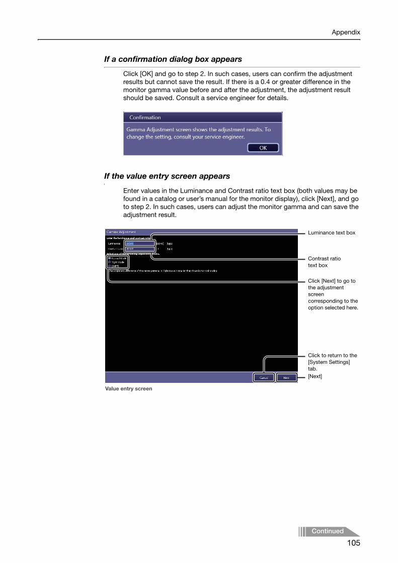
Appendix
If a confirmation dialog box appears
Click [OK] and go to step 2. In such cases, users can confirm the adjustment results but cannot save the result. If there is a 0.4 or greater difference in the monitor gamma value before and after the adjustment, the adjustment result should be saved. Consult a service engineer for details.
If the value entry screen appears
Enter values in the Luminance and Contrast ratio text box (both values may be found in a catalog or user’s manual for the monitor display), click [Next], and go to step 2. In such cases, users can adjust the monitor gamma and can save the adjustment result.
Click [Next] to go to the adjustment screen corresponding to the option selected here.
Value entry screen
Contrast ratio text box
Luminance text box
Click to return to the [System Settings] tab.[Next]
Continued
105

Appendix
2 Adjust the monitor gamma using luminance patches.
NOTE: Eight different luminance patches have a square at their center whose brightness can be adjusted by the use of the monitor gamma control. Adjust the monitor gamma so that all the eight squares inside each of the luminance patches are clearly and equally defined.
Point the monitor gamma control and rotate the scroll wheel on the mouse or click the arrows of the control.To brighten the center squares of the luminance patches, move the slider to the right.To darken the center squares of the luminance patches, move the slider to the left.
NOTE: It is recommended to lower the monitor gamma value if adjustment is performed in a darker room. On the other hand, raise the monitor gamma value if adjustment is performed in a brighter room.
NOTE: While the screens for Normal Mode and Tight Mode appear almost the same, lower contrast around the border of the center square of the luminance patch in tight mode is suited to fine-adjust the monitor gamma.
Luminance patches
Normal mode screen
Adjustment mode options
Click to return to the [System Settings] tab.
[OK]
Monitor gamma control
106

Appendix
3 Confirm the adjustment result using the SMPTE test pattern.
Select the SMPTE mode option from among the adjustment mode options. See step 2 in 2.3.2 for details on confirmation method.
NOTE: If required, monitor gamma can also be adjusted in this mode using the monitor gamma control.
4 End monitor gamma adjustment.
Click [OK]. The adjustment result is saved and the screen will return to the [System Settings] tab.
NOTE: If a confirmation dialog box appears in step 1, [OK] will be disabled and the adjustment results cannot be saved. In such cases, click [Cancel] to return to the [System Settings] tab, and consult your service engineer.
107

Index
AAccess privileges 75Age 22Anatomical Part 80APR ID 52Automatic analysis 92, 93Automatic Next Protocol Selection 22
BBackground color 34Backup
Database 71Birth 22Blank line 25, 29Body Part 50
CCalibration 59Called AE Title
MPPS 38MWL 36Printer 34Storage 31
Calling AE TitleMPPS 38MWL 36
Category tab 54C-ECHO
MPPS 38MWL 36Printer 35Storage 32
Character Set 18Classification of Imaging Parameters 75Code Meaning 51Code Value 51Column head items
Rearranging 47Column Headers 23Commitment Calling AE Title 33Commitment Port 33Common DICOM Output Settings 35Communication test result 33Connect GEN 12Connection 30Contrast ratio 105Create PrePack 55Customize Display 22
DData transmission
Resending 47Suspending 47
Database Backup 71Database server 36DB Backup 71Default Parameters 87Description List Items 23Device Information 18DI 25, 68Diagnosis images 92Disk Storage 39Divide Grid 42Dynamic Range adjustment 97Dynamic Range Analysis 95
EEI 25, 68EIt 25, 68Essential Input Setting 19Examination Screen 22Exposure Protocol Code 50Exposure type 52
FFilm Annotation 28Film Box Annotation 28Film Size 34Flipping and Rotation 51Free Annotation 26
GGamma Adjustment 20, 104GenCom 39Grid Name 51Grid Suppression 85GSPS
Storage 31GUI Color Taste Selection 22
HHelp Display 23
108

IImage Box Annotation 28Image Enhancement 99Image Feature Analysis 94Image Proc 66Image processing for diagnosis 92, 96Image Tone Transformation 96Image type
Print out 35Imaging administrators 75Imaging Parameters 75Input Reject Reason 22Institution Name 19Irradiated Fields 93
LLaterality 50Laterality Marker 26, 50Layout Template
Button 33Edit 41Screen 40
Local contrast 97Logout 46Luminance 105
MMeasurement Object 23Monitor Gamma 20MPPS 38MWL 36
NNoise Reduction 100Normal Mode 106
OOutput Exam Log 72
PPatient Info Input Mode 22Patient Orientation 50Performance Test 59, 62Peripheral Mask 85Per-protocol basis 77, 78Ping
MPPS 38MWL 36Printer 35Storage 32
PPS 46PrePack protocol
Creating 55Modifying 55
Pre-processed image 92Pre-processing 92Preview Annotation 24Print format
End Exam 35Printable area on an oversized image 51Printer 33Printer Calling AE Title 35Process Viewer
Button 46Refresh 18
Prolonged Exposure 52Protocol
Creating 53Modifying 48Settings 50
Protocol Editor 48Protocol Group
Edit mode 49
QQC Tool 58
RRadiography Image Modality 31Raw image 92Reference pixel value 94Reference tone curves 97Refresh Interval 18Regular users 75
109

SScreen Saver 18Selected protocol only 67Self-diagnosis 63Show Code Meaning 22Show Stitch Screen automatically after ending
every EXAM 22Shutdown 46SID 52Similar anatomical parts 67SMPTE 20, 107SOD 52Software Version 18Storage 30Storage Calling AE Title 33Storage Commit 31Study Parameters 78, 90System Settings 18System setup option 14System tool 44
TTight Mode 106
UUser Administration 16
WWorkspace
Edit mode 49Settings 50
ZZoom ratio 35
110


PUB. L-IE-4162C (Ver. 1.20) © CANON INC. 2010 Printed in Japan0910P0.001
CANON INC. Medical Equipment Group30-2, Shimomaruko 3-chome, Ohta-ku, Tokyo, JapanTelephone: (81)-3-3758-2111
CANON U.S.A., INC. CANON MEDICAL SYSTEMS15955 Alton Parkway, Irvine, CA 92618-3616, U.S.A.Telephone: (1)-949-753-4160
CANON EUROPA N.V. Medical Products DivisionBovenkerkerweg 59-61, 1185 XB Amstelveen, The NetherlandsTelephone: (31)-20-545-8926
CANON SINGAPORE PTE. LTD. Medical Equipment Products Division1 HarbourFront Avenue, #04-01 Keppel Bay Tower, Singapore 098632Telephone: (65)-6799-8888
CANON AUSTRALIA PTY. LTD. Optical Products Division1 Thomas Holt Drive, North Ryde, Sydney N.S.W. 2113, AustraliaTelephone: (61)-2-9805-2000