veil: research in knowledge representation for computer vision
TRANSCRIPT

VEIL:Research in Knowledge
Representation for ComputerVision
— Final Report —
Information Sciences Institute,University of Southern California
Los Angeles, California 90007
Submitted to theSoftware & Intelligent Systems Technology Office
Defense Advanced Research Projects Agency
Award Name: VEILAward Number: F30602–93–C–0064
Effective Date: 9/15/93Expiration Date: 12/31/96
Principal InvestigatorHerbert Schorr
Executive Director, Information Sciences Institute
Administrative Point of Contact:Beverly Hartmeyer
(310-822-1511, [email protected])


F30602–93–C–0064 VEIL Final Report
i
AAAAbbbbssssttttrrrraaaacccctttt
The VEIL (Vision Environment Integrating Loom) project focused on integratingadvanced knowledge representation (KR) technology with image understandingtechnology. VEIL to developed a more declarative approach to the construction ofvision systems and produced a tool that incorporates that methodology. Systemswere constructed in a more principled fashion that made it possible to share andreuse software across systems. Experiments in two main areas were carried out.We first demonstrated the utility of using Loom as a software engineering toolfor a specific vision application (runway detection). We also demonstrated thebenefits Loom provides for image understanding itself (event detetion).
The major innovations in this work are as follows:
1) applied a methodology that maximizes use of declarative knowledge (asopposed to procedural knowledge) in vision systems, thereby enabling us to applymodern software development techniques. The criteria for recognizing objectswas stated explicitly in a formal language (instead of being buried in code) makingit easier to understand and maintain an application and keep it consistent.Extending the recognition capabilities of the software was made easier.
2) use of this declarative system construction methodology to facilitate theprocess of integrating high-level vision routines (such as for recognizingsequences of scenes) with low-level routines that recognize picture elements.
3) enabling interaction with the system at a level of abstraction appropriateto the domain task. This includes associating collateral information with theobjects recognized by low-level image understanding programs.
4) development of a foundation for a vision ontology.
This work leveraged off the Loom Knowledge Representation system. Loomcaptures the best features of object-oriented programming, data-drivenprogramming, problem solving, and constraint programming, through the use ofan underlying logic-based representation scheme. This system is a powerful toolthat incorporates very strong, frame-based representation capabilities, explicitterm subsumption, and a number of powerful reasoning paradigms (includinglogical deduction, object-oriented methods, and production rules). Loom alsoprovides knowledge representation integrity through consistency checking, andprovides truth maintenance. Infusing these facilities into the vision problemarea, where strong KR capabilities have not yet been developed will significantlyalter and improve the methodology for the construction of vision systems. Wealso developed spatial and temporal reasoning capacities (critical for vision), alongwith mechanisms to exercise flexible control strategies and incremental sceneprocessing. Finally, Loom was interfaced to a variety of vision processingelements to provide a new tool of extended capabilities. The net result is apowerful software environment for the development of vision systems.

VEIL Final Report F30602–93–C–0064
ii
Table of Contents
Abstract ______________________________________________________________________________________________________ i
Part I. Introduction and Background _________________________________________________________1
1. Introduction______________________________________________________________________________________________________________________________ 1
2. Background ______________________________________________________________________________________________________________________________ 2
2.1 Other Related Work. ________________________________________________________________________________________________________________ 3
2.2 Overview of Loom Capabilities._________________________________________________________________________________________________ 5
2.3 Research Plan ___________________________________________________________________________________________________________________________ 62.3.1 Using Loom in an Existing Image Program._____________________________________________________________________________________62.3.2 Using Loom to Solve Domain Problems. _________________________________________________________________________________________7
2.4 Application Domain.__________________________________________________________________________________________________________________ 9
3. Report Organization_______________________________________________________________________________________________________________ 9
Part II. Loom Applied to the Implementation of Vision Systems.____________ 11
4. Software Engineering Experiment Overview__________________________________________________________________11
5. Declarative Programming__________________________________________________________________________________________________12
6. Airport Example____________________________________________________________________________________________________________________13
6.1 Runway Hypothesis Generation______________________________________________________________________________________________13
6.2 Runway Hypothesis Verification_____________________________________________________________________________________________17
6.3 Refinement of Hypotheses_______________________________________________________________________________________________________18
7. Using Knowledge Representation_______________________________________________________________________________________19
7.1 Representation Aspects____________________________________________________________________________________________________________20
7.2 Reasoning Aspects____________________________________________________________________________________________________________________21
8. Status and Results ________________________________________________________________________________________________________________22
9. Future Directions___________________________________________________________________________________________________________________24
Part III. Loom Applied to Domain Reasoning __________________________________________ 25
10. Domain Reasoning Experiment Overview ____________________________________________________________________25
11. Underlying Technology______________________________________________________________________________________________________26
11.1 RADIUS__________________________________________________________________________________________________________________________________26
11.2 Loom _____________________________________________________________________________________________________________________________________2611.2.1 Definitions ___________________________________________________________________________________________________________________________ 27

F30602–93–C–0064 VEIL Final Report
iii
11.2.2 Contexts_______________________________________________________________________________________________________________________________ 2811.2.3 Query Mechanism__________________________________________________________________________________________________________________ 28
12. The Domain Model______________________________________________________________________________________________________________29
12.1 Linking the Domain and Site Models_____________________________________________________________________________________31
12.2 Geometric Relations______________________________________________________________________________________________________________33
13. Event Detection____________________________________________________________________________________________________________________35
13.1 A Definition Language___________________________________________________________________________________________________________35
13.2 Sample Event Definitions ______________________________________________________________________________________________________35
13.3 Example of Event Detection___________________________________________________________________________________________________36
13.4 How It’s Done________________________________________________________________________________________________________________________36
14. Current Status _____________________________________________________________________________________________________________________37
15. Future Work _________________________________________________________________________________________________________________________38
Part IV. Conclusion. _________________________________________________________________________________39
16. Representation in Programs_____________________________________________________________________________________________39
17. Domain Level Reasoning __________________________________________________________________________________________________39
APPENDIX A Image Understanding Environment Support________________________ 41
APPENDIX B Model Board 2 Images ________________________________________________________43
APPENDIX C Vehicle Location Data_________________________________________________________55
Bibliography ____________________________________________________________________________________________59

VEIL Final Report F30602–93–C–0064
iv
List of Figures
Figure 1. Standard Runway Markings for Instrument Runway._________________________________________________________________ 13Figure 2. Runway Detection Algorithm.___________________________________________________________________________________________________ 14Figure 3. Boston and Los Angeles Airports.______________________________________________________________________________________________ 15Figure 4. Eliminate Contained APars.____________________________________________________________________________________________________ 16Figure 5. Join Common Segments.___________________________________________________________________________________________________________ 16Figure 6. Merge Colinear Apars Across Gaps __________________________________________________________________________________________ 17Figure 7. Big Distance Mark Description________________________________________________________________________________________________ 19Figure 8. Basic Runway Concept Definitions___________________________________________________________________________________________ 20Figure 9. Good Runway Concept Definitions ____________________________________________________________________________________________ 20Figure 10. Boston: Excellent Runways____________________________________________________________________________________________________ 23Figure 11. Los Angeles: Selected Runways_____________________________________________________________________________________________ 23Figure 12. Vehicle Hierarchy of the Domain Model___________________________________________________________________________________ 27Figure 13. Domain Model for Visible Objects in VEIL ________________________________________________________________________________ 30Figure 14. Image M16 — Plain and with Model Overlay___________________________________________________________________________ 32Figure 15. Extended Bounding Boxes for Computing Nearness_____________________________________________________________________ 34Figure 16. Event Definition and Corresponding Loom Query_______________________________________________________________________ 35Figure 17. Field Training Exercise Event Found in an Image Sequence________________________________________________________ 36Figure 18. Close-Up View of Field Training Exercise_________________________________________________________________________________ 37Figure 19. Map of Model Board 2__________________________________________________________________________________________________________ 43Figure 20. Image M 4__________________________________________________________________________________________________________________________ 44Figure 21. Image M 6__________________________________________________________________________________________________________________________ 45Figure 22. Image M 8__________________________________________________________________________________________________________________________ 46Figure 23. Image M12_________________________________________________________________________________________________________________________ 47Figure 24. Image M16_________________________________________________________________________________________________________________________ 48Figure 25. Image M19_________________________________________________________________________________________________________________________ 49Figure 26. Image M24_________________________________________________________________________________________________________________________ 50Figure 27. Image M27_________________________________________________________________________________________________________________________ 51Figure 28. Image M32_________________________________________________________________________________________________________________________ 52Figure 29. Image M33_________________________________________________________________________________________________________________________ 53
List of Tables
Table 1. Geometric Functions and RCDE Objects ______________________________________________________________________________________ 33

F30602–93–C–0064 VEIL Final Report
1
Part I.
Introduction and Background
1. Introduction
VEIL was implmentented and tested in the area of aerial photointerpretation.The application makes use of high-level reasoning and knowledge representationfacilities provided by the Loom system to produce more capable implementationsthan is possible without such facilities. This application is interesting and usefulin its own right, and complements other related research programs funded byDARPA. Experience with the application has validated the VEIL methodologyand provides guidelines on how other applications may be implemented in VEIL.
VEIL addressed the need to incorporate strong knowledge representationcapability within computer vision systems. Many previous approaches to imageunderstanding addressed the need for knowledge representation, but none tookfull advantage of the strong technology that had been built up in this area overthe past decade for other areas of AI. At the same time, traditional knowledgerepresentation research had not paid particular attention to the unique demandsthat would be required for successful application of knowledge representationtechnology to the demanding computer vision problem. We adapted the LoomKnowledge Representation System to computer vision needs. The researchfocused on integrating advanced knowledge representation (KR) technology withappropriate image understanding technology to develop a substantive and uniquetool, called VEIL (for Vision Environment Integrating Loom), for generation ofvision systems.
The Loom system supports the construction and maintenance of “model-based”applications—Loom’s model specification language facilitated the specification ofexplicit, detailed domain models. Its underlying knowledge representation systemprovided powerful built-in tools for reasoning with domain models, and itprovided a variety of services for editing, validating, and querying the structureof Loom models. Vision applications benefited from adopting a more declarativeapproach to software specification in three different ways, all of which weregained by using a system like Loom:
1) The use of explicit, declarative knowledge structures, which made anapplication easier to debug and maintain. For example, the object recognitionprocedures encoded in a vision application were easier to identify, comprehend,and explain when they were phrased in a declarative rather than a procedurallanguage.
2) The implementation of symbolic computation, which played anincreasingly important role at the higher levels of vision processing. At these

VEIL Final Report F30602–93–C–0064
2
levels, significant leverage was obtained by using Loom’s deductive reasoningfacilities.
3) Finally, by declaratively specifying modules within a vision applicationthat were easier to share and reuse. The use of declarative models served as acomplement to evolution towards standards such as the Image UnderstandingEnvironment (IUE).
2. Background
Image understanding programs often incorporate a number of representationsthat were amenable to representation in a general KR formalism. However, dueto the need to represent many other objects outside a formal KR system, imageunderstanding systems generally used ad hoc methods at all levels ofrepresentation, thereby failing to take advantage of the strong capabilities thathad been developed for this kind of technology in systems such as Loom. In thevision context, Loom provides control mechanisms for reasoning and a means ofrepresenting scene knowledge.
Loom incorporated previous and current research in knowledge representationand inference technology into a system designed to be used directly byapplications programs. Loom was a continuously evolving system—each release ofLoom supported additional reasoning capabilities, and for the past several years anew version of Loom was released approximately once every year. Loom has beendistributed to over 80 universities and corporations.
The functionality, in terms of representational and inferential power, that Loommade available to users exceeded that delivered by current-generation expertsystem shells, while the inference technology represented by Loom's descriptionclassifier had no analog in that technology. A key feature of Loom was thehigh-level of integration between its various embedded inference technologies,as demonstrated by the fact that typical Loom applications made use of threedistinct programming paradigms (data-driven, object-oriented, and logicprogramming). Because Loom supports a more declarative style of programming,applications constructed using Loom have been easier to debug, maintain,explain, and extend than those based on that current-generation technology.These benefits were derived partly from the inherent nature of the language,and partly from the powerful support tools that the language made possible.
Within image understanding applications, such as aerial image analysis andvehicle navigation, many different kinds of basic objects are extracted from theimage. These included image pixels (intensity, color, or range), individual edgeelements from intensity or range images, connected edge elements, line segmentapproximations to the connected edges, edge-based contours, connected regions,surfaces, collections of regions or surfaces, and collections of other basic objects.All of these descriptions may have also had information regarding the viewingposition or time for a sequence of data. Some of these were derived from other

F30602–93–C–0064 VEIL Final Report
3
representations in the list and were possibly linked to each other by spatial orsemantic relationships.
Many of these object descriptions represented well-defined image structureswith well-defined extraction techniques, and were not usually represented in thesame terms that were used by knowledge representation systems. Nor was itdesired that such a system as Loom attempt to embody every kind of object.Rather, the interest in a formal KR technique was for the power it brings to bearon the middle and high levels of image analysis, not the very low levels. Forexample, in the earlier aerial analysis system developed at USC/IRIS [Huertas90], extraction of runway structures proceeded in a direct fashion from edgedetection and line segment formation through extraction and verification ofrunway rectangles. These early stages of analysis were time consuming andentailed processing many (50,000+) basic elements to find the candidatestructures. The techniques used were highly specialized processes which Loomcould not improve upon. However, when further analysis of the aerial image wasundertaken to extract higher levels of potential structure (e.g., taxiways,buildings, airplanes), using models of these same structures (via Loom'srepresentation system), along with Loom’s powerful reasoning capabilities, offereda new disciplined approach to handling this phase of the recognition problem,which constituted a marked improvement upon the then existing techniques. Thus, the VEIL system was able to combine the data-driven geometric reasoningmodules specified above with model-driven symbolic reasoning tasks under asingle programming environment to produce a more powerful tool than eithersystem could have provided alone.
An additional problem with previous systems was that even when high-levelknowledge was used, much of the information about the structure of the scenewas embedded in the programs implementing the extraction (proceduralknowledge representation) rather than in a declarative form. This made anychanges and addition of knowledge for domains difficult. The Loom KR systemincreased the amount of declarative knowledge representation that could be done,thereby alleviating the problem.
2.1 Other Related Work.
There have been several attempts to develop high-level reasoning systems forimage understanding. Three such systems, described below, are: SPAMdeveloped by McKeown and his colleagues at CMU [McKeown 89]; VISIONSdeveloped by Hanson, Riseman and colleagues at University of Massachusetts[Draper 89]; and ICC [Silberberg 87] developed at Hughes Research Labs. Webelieve that all of these systems suffered from the major drawback that theyforced one to commit oneself to developing large vision systems with a singleinference engine, whereas there were and are many tasks in vision better handledby different control structures. The Loom knowledge representation system

VEIL Final Report F30602–93–C–0064
4
allowed the system designer to combine various control/knowledge representationparadigms in an explicit fashion.
SPAM was developed for and had been applied to aerial image analysisapplications. It was basically a rule-based system implemented in OPS5. Itprocessed a given image in the following phases: segmentation, classinterpretation (of segmented regions), fragment interpretation, functional areaanalysis and finally, model generation and evaluation. Some interaction betweendifferent phases was possible. SPAM handled the demands of low level and highlevel analysis and handled the large data accompanying aerial images. Weevaluated the drawbacks of SPAM to be in specific commitments to the mannerin which images must be analyzed, and in largely procedural representations ofknowledge, which obscured the control knowledge any designer wishes to expressin this system. Under Loom, the problem solving strategy was explicit and easilymodified to allow the designer to experiment with different structures.
VISIONS was essentially a “schema” or “frame” based system. Knowledge abouteach object was encoded in a schema, which was specialized to find an instance ofthis object. Schema instances communicated with each other via a globalblackboard. This architecture had some advantages for parallel implementation.VISIONS was a very general purpose system that could, at least in principle, beapplied to a variety of domains. In VISIONS, the knowledge representation wasprimarily procedural and many of the schemas needed to be about intermediateobjects for which we had no intuition.
The ICC system had been used to represent and apply high level domainknowledge to target detection. An object was modeled, using frames, accordingto its 2D appearance in the image using collections of regions and lines, takinginto account spatial, temporal, and contextual knowledge. A semantic networkwas used to represent a limited amount of relationships between objects. Theimage features were represented in the Symbolic Pixel Array [Payton 84] whichallowed efficient retrieval of pixel and object properties and object spatialrelationships. The analysis, which was both bottom-up and top-down, followedthe hypothesize and verify paradigm; when an object was hypothesized, itgathered information for its slots which provided evidence for or against thehypothesis. A confidence measure for a hypothesis was computed based on thedegree of belief and disbelief provided by the evidence. The declarative natureof the modeling in ICC was analogous to representation in Loom. There were atleast two problems in ICC: first, the search strategy in ICC was computationallyintensive for large numbers of scene objects, and second, the semantic networkrepresentation in ICC was limited.
Our objective in VEIL was to build a system that allowed for more declarativeknowledge representation, where the generic vision processing (such as some ofthe geometric reasoning) was separated from the domain knowledge. In addition,it provided multiple reasoning techniques, something which was particularly

F30602–93–C–0064 VEIL Final Report
5
appropriate for machine vision. We believed that these attributes were missingin the previous systems such as SPAM, VISIONS, and ICC, and were of greatadvantage for programming, in general, and image understanding, in particular
By encouraging users to represent significant portions of their vision applicationsin VEIL, we made available to them a large variety of features (including termsubsumption reasoning [MacGregor 90b], role hierarchies, multiple knowledgebases, etc.) that were absent in the frame systems found in existing visionprocessing systems.
2.2 Overview of Loom Capabilities.
Loom [MacGregor and Bates 1987, Brill 1993] provides a very expressive domainmodelling language, an integrated suite of deductive reasoners (for performinggeneral symbolic processing), and an environment for creating, editing, viewing,and saving knowledge base objects.
Loom has an immediate means for representing non-spatial properties of objectmodels and model instances. For the vision domain, Loom was to be extended byadding spatial representations for two and three dimensions. The extensionincluded specialized procedures to compute spatial properties such as whatobjects were located at a pixel or at a location in the world, and how objects werelocated with respect to one another. Frequently, the answer to a spatial questionposed at the symbolic level was computed by descending a level down andperforming computations with the more detailed spatial structures thatinhabited that lower level.
The Loom system provides a powerful set of tools for formally defining thevocabulary and operations that applied to an application domain. Terms definedin Loom were automatically checked for consistency. Unlike the more primitivedatabase notion of a “view relation,” which could only be used within databasequeries, a Loom term defined a concept that could be used within assertions aswell as within queries. Once defined, a term could be used throughout a Loom-based application to promote the uniformity and conciseness of expressions thataccessed the knowledge base. Loom’s term definition facility was key to derivingan ontology that could be shared across multiple applications, as described below.
Concurrent Loom development resulted in new extensions to the system, and asupport environment for Loom enhance d its usability. Contexts were addedand expanded in Loom in order to support VEIL reasoning. In particular, contextswere made into first class objects with the ability to make assertions. This madethe use of contexts as a representation for individual images more convenient andallowed the rapid development of an event detection capability. A Web-basedsupport environment for Loom called Ontosaurus was recently released thatcontains tools to facilitate browsing, querying, and editing Loom knowledge bases.Tools exist that enable Loom to retrieve data stored in a relational DBMS, and

VEIL Final Report F30602–93–C–0064
6
future plans call for interfacing Loom’s successor to a persistent object storagesystem.
2.3 Research Plan
Our plan of work was straightforward. We developed a new vision programmingenvironment tool, VEIL, that integrated powerful knowledge representationcapabilities with useful vision processing techniques. To accomplish this end, weused the Loom knowledge representation system as a basis, extended it forapplication to vision system problems, incorporated vision processing algorithms,and applied the resulting tool to two image understanding problems todemonstrate its utility. Since efficiency was such a major issue for visionsystems, we also evaluated the resulting system and improved performancewhere indicated. It was our view that the resulting system would offer majornew capabilities to declaratively model vision problems, apply new kinds ofreasoning to the vision problem, and to make the construction and maintenanceof vision systems easier and more cost effective.
The research was conducted in two phases. The first phase demonstrated theutility of Loom as a high-level mechanism which could provide a much neededfacility for knowledge representation within the image understanding (IU)domain. Following successful demonstration of the utility of Loom for thispurpose, we undertook development of additional capabilities for Loom whichaddressed the particular requirements of the IU domain. These new capabilitieswere demonstrated on a slightly different problem than that used for the basiceffort. We describe the basic effort immediately below. These two phases aredescribed separately in Parts II and III of this report.
2.3.1 Using Loom in an Existing Image Program.
Our objective was to explore how Loom applies to programs used in the computervision problem domain. We chose the runway detection and analysis task sincewe already had a “hard coded” version of the program, we had experience inhelping with the transfer of this application to a Prolog based system, and thisprogram operated at several different levels of analysis (low-level image analysisand higher-level geometric reasoning).
This runway detection system has grown and developed over a number of years,but it has not been easy to modify it to work on different problem domains, or toextend it in the current domain. This failure is due partly to the lack ofgeneral knowledge representation and reasoning capabilities which would allow abetter separation of the knowledge about airports used in the analysis and theprograms that implement the analysis.
Vision techniques, such as line finding, segmentation, perceptual grouping, and3-D shape descriptions, were integrated with the Loom system. To accomplish

F30602–93–C–0064 VEIL Final Report
7
this goal, we had to discover methods of tying the reasoning provided by Loom tomid- and low-level processing techniques that were common in the visioncommunity. Finally, we developed incremental control strategies designed toreason about specific objects or regions within an overall scene so that objects ofhigh interest could be rapidly recognized.
The low-level processing (e.g. edge and segment extraction, initial grouping) didnot benefit from the general representation and reasoning schemes of Loom andremained in Lisp. The higher-level analysis was better suited to using reasoningand representations available in Loom. These included the reasoning about whereto look for other airport structures given the initial runway locations, analysis ofconnections between these structures, and a more general description and analysisof the markings on the runways. Given this reasoning, we approached the use ofLoom in an incremental fashion by first developing the higher-level analysis andknowledge in Loom and only later moving the use of Loom to the middle andlower level processing. Having these capabilities at all three levels then allowedus to incorporate feedback mechanisms that explored the images for furtherevidence and process portions of images at higher resolutions.
2.3.2 Using Loom to Solve Domain Problems.
Loom had already provided powerful representation and multiple reasoners suchas logical deduction, object-oriented methods, and rule production. Loom wasdeveloped for more traditional AI problems and does not have some of thecapabilities required for computer vision, such as a geometric reasoningcapability, thus a part of the experiment identified the current limitations anddeveloped techniques to address them.
For VEIL the following capabilities were added to Loom: spatial representation andreasoning; flexible control of instance recognition and classification; andincremental scene processing. In the area of spatial reasoning we added newconstructs for representing such notions as coordinate location (2-D and 3-D),regions, distances, and nearness and adjacency relationships. Furthermore, weintegrated the high-level representation of Loom with visual recognitionprocesses exploiting geometrical and/or functional descriptions of physicalobjects. The method we used is similar to the technique used by Haarslev[Haarslev et al., 1994].
Spatial Reasoning. As discussed above, VEIL implemented multiple spatialreasoning algorithms designed to process both high and low levels of spatialrepresentations. The spatial reasoner for top level (symbolic) knowledge washandles relatively general, declarative representations of spatial knowledge. Thelower-level processing was performed by one or more special-purpose algorithmsalready developed for other vision processing systems (e.g., [Payton 84]). One ofour tasks was to write a query translator to transform symbolic spatial queriesinto equivalent queries on the lower level knowledge structures.

VEIL Final Report F30602–93–C–0064
8
For our vision applications, we expected that most symbolic spatial knowledgewould be created through the process of abstracting lower level spatialrepresentations. One of our tasks was to implement a VEIL component to performsuch abstractions. Thus, the system would have the option of answering querieseither by translating symbolic level queries into lower level queries, or byabstracting relevant spatial knowledge into the symbolic level, and thenprocessing the query at that level. The latter method left the system with theoption of saving (caching) the abstracted knowledge, One example of this involvesthe use of a declarative description of a convoy as “a group of vehicles located ona road.” Once a particular group of vehicles is recognized as being a ocnvoy,further queries and processing no longer needs to reference the low-level objectsthat make up that convoy.
Our architecture overlayed a declarative spatial representation on top of a highlyoptimized spatial reasoner that used specialized representation structures tunedto the needs of high performance algorithms. If the vision processingcommunity achieves standardization of data structures and algorithms forrepresenting and reasoning with spatial knowledge during this contract, we willinvestigate the possibility of converting our architecture to match that standard.Placing a high level layer of reasoning above such a standard would yield ameans for delivering high performance spatial reasoning to a relatively widecommunity of users. It also allowed us to develop a capability to detect events,which are sequences of images with domain importance. Armored movementsand field training exercises are examples of such domain-level events.
Temporal Reasoning. Detecting events meant that capability for representingand reasoning with temporal knowledge was needed. We used the contextmechanism added in Loom version 3.0 in order to implement a snapshot temporalmodel. This provided a natural representation for a series of images taken atdifferent times. For monitoring a given site for changes, we were also able toexploit the hierarchical nature of Loom contexts to allow a shared backgroundmodel. This “site model” provides a single, shared repository for informationthat does not vary with time. Most of the buildings and terrain can thus beshared among all of the individual “image models.” The individual image modelsallowed the tracking of the positions of vehicles as they moved from one image toanother. The ability to create queries that spanned several images made theconstruction of an event detector straightforward.
Enhanced Understandability. In addition to guiding the system, the use of adeclarative domain model (particularly one expressed in Loom) has other benefitsas well. Declarative representations of knowledge are in general easier for ahuman to understand than procedural representations, since all knowledge isexplicit. Also, inferences derived from a base of declarative knowledge areexplainable—a relatively straightforward derivation of support had to exist foreach derivable fact. Practical benefits were that declaratively representedportions of a program were in general easier to debug and maintain (because they

F30602–93–C–0064 VEIL Final Report
9
were modular and explainable), easier to extend (because of their modularity),and easier to share and reuse (because declarative representations reduce the useof clever or obscure encodings of knowledge). For these reasons, it was desirablethat significant portions of an application be represented declaratively.
2.4 Application Domain.
In order to provide operational feedback, and to evaluate the success of ourendeavors, we applied the evolving tool to a common vision domain, namely thephotointerpretation of aerial imagery. This domain is of vital importance to themilitary and contained a rich variety of objects, both man-made (buildings,transportation networks, power transmission lines, and pipelines) and natural.Most of the objects are stationary but mobile objects are also present. The testdomain is explained in more detail later.
The domain of aerial images contained a rich variety of man-made and naturalobjects. Major man-made objects included buildings, transportation networks(roads, railroads, runways etc.), power transmission lines, and pipelines. Most ofthese objects were stationary and changed slowly, but important mobile objectswere also present (trucks, cars and airplanes). The images also contained naturalterrain and vegetation. Some of the objects were very large with complexstructures, while others were very small.
Typical aerial images were of “natural” scenes, where neither the illuminationnor the nature of the observed surfaces could be easily controlled. This impliedthat, not only was the domain complex, but also the signal that we had to startwith was far from ideal; usually, low level algorithms produce segmentationsthat differ significantly from the desired result. This richness and complexitymade the task of aerial image analysis extremely challenging.
3. Report Organization
A detailed report of the application of Loom to the development and extension ofan existing program for runway detection is described in Part II of this report.The application of Loom to the problem of integrating higher-level knowledgeand detecting semantically meaningful events is described in Part III. Part IVprovides a summary.
Appendix A reports on related support work for the Image UnderstandingEnvironment (IUE). This work was also performed as part of the VEIL contract.The Image Understanding Environment represents a major step towards theintroduction of sharable object oriented specifications into the vision domain. Theintended domains of the IUE and VEIL have some overlap, but the IUE explicitlydoes not consider higher-level knowledge representation issues or reasoningtechniques.


F30602–93–C–0064 VEIL Final Report
11
Part II.
Loom Applied to the Implementation
of Vision Systems.
The first part of the VEIL project focused on integrating advanced knowledgerepresentation technology (provided by Loom) with current image understandingtechnology to develop advanced tools for the generation of vision systems. Thiseffort was aimed at eliminating a weakness in computer vision technology in therealm of higher level representations. The resulting hybrid system exhibitsimproved shareability, maintainability and reusability of code for computervision systems.
4. Software Engineering Experiment Overview
VEIL integrates advanced knowledge representation technology (as developed inLoom) with image understanding technology to develop advanced tools for thegeneration of vision systems. The goal of this part of the project is to improvecapabilities in high level computer vision systems through the use of mature,highly developed knowledge representation and reasoning techniques. We usedadvanced knowledge representation for computer vision to improve shareability,reuse and to simplify the development of high level vision programs. We haveapplied the Loom knowledge representation language to existing computer visionprograms with an improvement in readability and extensibility without asubstantial loss in execution time.
This experiment investigated the benefits available to vision applicationsobtainable via the introduction of declarative programming techniques,specifically, techniques available using advanced symbolic processing technologyfound in a modern knowledge representation system. In typical vision applicationstoday, a programmer invents specialized data structures and carefully crafts asuite of vision processing algorithms that exploit those data structures. Theresult is most often a highly specialized piece of code that cannot be reused for adifferent domain, or applied to applications other than the one originallyintended. The Image Understanding Environment [Mundy et al. 1993] addressessome of these issues, including sharing and reuse of basic data structures andprocessing algorithms, but does not deal with higher level representation issuesthat are the focus of this work.
The VEIL project aims to develop a technology whereby much of the work thatgoes into the development of specialized vision processing modules results insoftware that can be shared or reused by multiple applications. Knowledge

VEIL Final Report F30602–93–C–0064
12
representation techniques have been a part of computer vision research from thebeginning (for example see [Winston 1975, McKeown et al. 1985, Draper et al1989]). One difference is that this project combines an existing powerfulknowledge representation system with relatively mature computer visionprograms and techniques. This project will form the basis for incorporatingknowledge representation technology in future computer vision research.
In order to study the knowledge representation issues directly, we transformedan existing mature program for runway detection and analysis into one builtusing the Loom system and declarative programming techniques. This strategyhas several advantages. First, we know that the algorithm works, and second, wecan directly explore the benefits of using knowledge representation technology.This paper will discuss some of the issues of declarative programming, brieflydescribe the airport analysis system, and present results of the effort inincorporating knowledge representation in computer vision.
5. Declarative Programming
Domain knowledge may be represented procedurally, as program code, ordeclaratively. Declarative representations take many forms, but the distinction isthat the representation itself is not executable program code but is data used bythe program. A declarative specification provides a formal, semantically well-founded description that offers numerous benefits. Such a specification is morereadable and easier to maintain and is subject to automatic validation andverification techniques. The description uses a high-level language specification,thus it does not rely on a specific choice of data structures. Algorithms arespecified by the heuristic rules they employ and/or the changes they effectrather than by how they operate. Finally, the descriptions can be shared,modified, and reused by other applications more easily than proceduralspecifications.
The key approach in VEIL is the application of declarative programmingtechniques to vision processing, leveraged by the reasoning capabilities of theLoom knowledge representation system. We use declarative descriptions for thegeneric objects such as a runway and the markings on a runway to control theprocessing of the data. We use Loom’s classification, query and production rulecapabilities to select the final objects from the scene. A declarative specificationof an application (or even a portion of an application) provides a formal,semantically well-founded description that offers numerous benefits. Such aspecification
• is more readable and easier to maintain than a procedurally-specifiedprogram;
• is subject to automatic validation and verification techniques;

F30602–93–C–0064 VEIL Final Report
13
• represents a high-level language specification. Thus, it does not rely on aspecific choice of data structures. Algorithms are specified by the heuristicrules they employ and/or the changes they effect rather than by how theyoperate;
• can be shared and reused by other applications.
6. Airport Example
We developed a project to explore the use of standard knowledge representationtechniques in computer vision. The goals of the project include improvements inboth computer vision and knowledge representation techniques. To this end, westarted from a relatively mature application and incrementally changed theprogram to replace procedural specifications of knowledge with declarativerepresentations of knowledge.
Detection and analysis of aerial views of airports provide the first application forLoom. This application defines primitive concepts for such objects as runways,center stripes, blast pad markings, distance markings, and taxiways. [Huertas, etal. 1990]. Each of these primitives is a long thin ribbon (represented as an imagefeature called an apar), though the size and relations among them vary. Figure 1shows the common markings for an instrument runway.
1 5 1 5
5 05 05 0
1 4 77 21 6
3 06 / 5 '1 2 / 3 '
7 5 7 5
5 05 05 0
7 5 7 5 7 5
8
Figure 1. Standard Runway Markings for Instrument Runway.
Airports are described by a generic model: a collection of generic runways, whichare long thin ribbons with markings (smaller ribbons) in specific locations. Oursystem locates potential runways through a sequence of filtering and groupingoperations followed by a hypothesis verification step. Since these are described indetail in [Huertas et al 1990], we will give only a brief description of thesetechniques in this report.
6.1 Runway Hypothesis Generation
The basic steps in finding runway hypotheses (which are also used for thetaxiway hypothesis generation) are described in the flow chart of Figure 2.Runway generation begins by generating two sets of edges, stronger edges for the

VEIL Final Report F30602–93–C–0064
14
runways and weaker edges for the markings. These edges are grouped intostraight line segments and then grouped into anti-parallel pairs (ribbons, orapars). The runway hypothesis generation then proceeds through a series offiltering and grouping steps: Filter out contained apars, group apars sharing acommon segment, and group colinear apars across gaps. Twice, the results arefiltered to remove very short runway fragments (aspect ratio filtering). Thesesteps produce a reasonable number of hypotheses (e.g. 14) from the original set ofmany ribbons (e.g. 18,000). The numbers of objects (i.e. 26,410 segments) aretaken from the Boston Logan International Airport example. They are typical ofthe numbers for other airports.
Canny Edge detector [Canny1986] and Line GroupingMask size 9, Strength 1026,410 Segments
Group Lines into Anti-parallel pairs (Apars)[Nevatia and Babu 1980]20 to 60 pixels wide18,591 Apars
Find Dominant Directions5,545 Apars in 3 directions
Eliminate Contained Apars(See Figure 3).1,714 Apars
Join on common segmentAspect Ratio Filter (1:1).(See Figure 4)551 Apars
Merge across Gaps and applyAspect Ratio Filter (10:1).(See Figure 5).14 Apars
Canny and Line GroupingMask size 7, Strength 857,882 Segments
Group Lines into Anti-parallel pairs (Apars)1 to 12 pixels wide18,424 Apars
Runway Verification4 Verified
InputImage
Figure 2. Runway Detection Algorithm.

F30602–93–C–0064 VEIL Final Report
15
The details of the algorithm are described below.
• Generate edges using e.g., the Canny edge detector [Canny 1986]. Findconnected sequences of edge elements and form straight line segments fromthese curves [Nevatia and Babu 1980]. Two sets of edges and line segmentsare generated, one with a relatively large mask (size of 9) and high threshold(strength of 10) for runway hypotheses and the other with a smaller mask(size of 7) and lower thresholds (8) for markings. These result in 25,000-90,000 line segments for typical images.
• Group straight line segments into anti-parallel pairs (that indicate ribbons),called apars. These pairs are limited by width (one set for markings isnarrow, about 1 to 12 pixels, and the other set for potential runways ismuch wider, around 20 to 60 pixels). These widths are based on very roughapproximations of the image scale and the generic description of the possiblerunways (which have defined limits on widths) and markings (which havevery specific widths). The program generates 18,000 to 35,000 apars forthe images.
• Find dominant directions using a histogram of apar directions. The apar isweighted by its length in the histogram accumulation. The histogram shouldhave a few very dominant peaks, which correspond to runway directions.The later processing is applied to selected apars for one direction at a time(except for taxiways) which greatly reduces the computation time. Similarhistogram analysis on widths could be used to further restrict the validrunway widths, but is not needed. This reduces the set of apars from18,000 to 1,000 to 3,000 for airports with runways in multiple directions(Boston, Figure 3). The reduction in numbers is similar for other examples,but much less pronounced for airports with all runways in the samedirection (Los Angeles, Figure 3).
Figure 3. Boston and Los Angeles Airports.

VEIL Final Report F30602–93–C–0064
16
• Eliminate apars contained within larger ones. This noise-cleaning stepreduces the number of elements to analyze. The extra apars, which areeliminated, have many causes, but most are caused by the markings (i.e. anapar formed by the two sides of the runway, and two more formed by theside and the center stripe). Figure 4 illustrates this operation. Typically,about one-third of the apars survive this filtering.
Figure 4. Eliminate Contained APars.
• Join apars that share a common line segment. These breaks in large apars arecaused by a gap on one side. This operation maintains colinearity (since theline segment is straight) and creates new merged fragments that were not inthe original image data. After this step, reapply the previous step toeliminate contained apars. Figure 5 shows how this operation works,reducing the total number of apars by about 10% to 15%. At this point afiltering on aspect ratio is applied to remove very short hypotheses fromfurther consideration (ratio of length to width less than 1). This removesabout half of the remaining hypotheses (with about 150 to 250 remaining).
Figure 5. Join Common Segments.
• Merge colinear apars across gaps. The gaps are formed by missing edge andapar data, by actual crossing runways or other occlusions. This step alsocreates new merged fragments. The gap must be analyzed to determine ifthe merger is valid (e.g. taxiways do not cross runways). This step has thepotential for serious errors if the allowed gaps are too large (or too small) andif the definition of colinear allows the hypothesis direction to drift. Figure 6

F30602–93–C–0064 VEIL Final Report
17
shows this operation. This reduces the total number of fragments to roughlytwo-thirds of the previous number. A second aspect ratio filtering (greaterthan 10) is applied here to get the final hypotheses (for the Boston image 4or 5 remain for each of the three directions).
Figure 6. Merge Colinear Apars Across Gaps
These filtering operations depend only on a generic description of the runway andare all relatively efficient operations given the right data structures (especiallyspatial index). In the original reports on this effort, the run times were verylarge. Most of the reduction came from using data structures such as the spatialindex to greatly reduce searches through the data.
6.2 Runway Hypothesis Verification
The verification step requires analyzing the hypotheses to find the specificmarkings. Figure 1 illustrates the markings for an instrument runway. Thedimensions and spacings are given in feet. Each marking would appear in theimage as an apar of a specific size (e.g. 30 feet wide and 150 feet long). Using aninitial scale gives the size range for each marking apar, an indication of itsposition relative to other markings and relative to the runway hypothesis.Knowledge representation systems do not currently support spatial reasoning forsearches so the details of the search fall on the image analysis system.
First the true ends of the runways must be located. The positions of themarkings on the runway are well defined once the true end of the runway isknown. But, the hypothesized end of the runway is not always the true end dueto errors in the input or extensions of the paved runway surface. The true endsof the runway are indicated by the threshold marks (top left of Figure 4). Ratherthan find the marks themselves, it is easier to find the apar in the center of therunway formed by the gap between the two marks. The threshold mark is

VEIL Final Report F30602–93–C–0064
18
located by searching along the center line of the runway hypothesis to find therelatively dark apar of this gap. Once the threshold mark is found the otherdistance marks are located relative to it. Each mark is located by looking forapars in the appropriate locations and selecting according to the description ofthe marking.
At this stage in processing, the image scale is approximately known but theprogram does not assume it has the exact scale or the exact position of thethreshold marks. Furthermore, in the original edge and feature extraction, thelarger marks are often broken into shorter apars. Therefore the extraction allowsfor a considerable tolerance in the location (especially along the runway) and sizeof the marks (especially the length). The initial set of markings is used to refinethe scale and then to filter out other markings in incorrect positions.
Center lines and side stripes are found by looking for marks in specific locationsrelative to the runway hypothesis (in the center, along either side). Both of theseare very narrow (roughly 1 pixel) so they tend to break up into many smallpieces.
6.3 Refinement of Hypotheses
The initial markings are located using the large set of apars generated by theglobal edge detection process at the beginning. This is sufficient for finding well-defined markings, but some runway markings are missed due to errors in theanticipated position, errors in the edge detection, the thresholds used for theedge detection, or because they are very low contrast in the image. Furthermore,the markings are near the image resolution limit with widths of one or two pixelsfor the smaller markings. All of these problems are countered by the refinementsteps.
More markings are located by reapplying the edge, line and apar findingprocedures on small windows (50 by 50 pixels) of the image with very lowthresholds and using a replicated version of the image so that small marks can bereadily found. Also, by using the locations of previously found markings, theimage scale can be determined more precisely and the expected location of thenew marks can be specified more exactly (i.e. relative to other establishedmarkings). The same processing used to evaluate candidates for the original set isused for the refinement, except that the input is taken from the data extractedin the window in the image rather than taken from the globally extractedfeatures. Descriptions of the size and location of marks are used to rule outcandidates and to determine if the extracted apars are appropriate. Loomprovides support for the creation and use of such descriptions. This wasexploited in the new implementation.
Additional refinements include merging the many side stripe fragments using thesame procedure used for runway hypotheses, which reduces the number of

F30602–93–C–0064 VEIL Final Report
19
individual side stripe fragments to one-tenth of the original numbers. Theupdated scale information is also used to eliminate distance marks that werewithin the original ranges, but are not close enough when the scale is knownmore accurately.
In the initial implementation, all the size and position information was specifieddirectly in the extraction and analysis procedures. The first part of this projectrewrote these procedures to use Loom to describe the markings (sizes, relativepositions and position on the runway). This simplified the implementation (byreducing the number of procedures) and moved all the descriptions into a moreunderstandable form (i.e. the Loom descriptions). Figure 5 gives the Loomdescription for big distance marks (called this by the program because of thephysical size of the marking). From this, we know that a big-distance mark is atype of generic-mark (which in turn has several roles (or slots)). We also know thedistance between this marking and other marks and the spacing (across therunway) between pairs of big distance marks. This shows the basic properties ofthe marking and the relations between it and other markings. Some propertiesand relations could be described as relations to the underlying runwayhypothesis, but these geometric relationships would require extensions to Loom.
7. Using Knowledge Representation
Through the initial hypothesis generation and initial verification, there is littleuse of any high level knowledge representation techniques. For this basicanalysis, Loom concepts are used to:
• describe the elementary objects, such as the runway length and width, thetypes and shapes of the markings;
• describe the constraints on objects, such as the required distance betweenvarious types of markings, or the number and kinds of markings that mustbe located. An example of big distance marks is given in Figure 7;
(tell (create big-distance generic-mark) (about big-distance (width-in-feet 30) (length-in-feet 150) (distance-between touchdown 500) (distance-between small-distance) (distance-between threshold 1000) ) (spacing-between 102)))
Figure 7. Big Distance Mark Description
• describe different classes of runways based on quantitative (and qualitative)differences in the set of markings. These are illustrated by Figure 8, whichshows several basic runway types;

VEIL Final Report F30602–93–C–0064
20
(defconcept A-Runway :roles (runway-object))
(defconcept A-Runway-Taxi :is (and A-Runway (at-least 4 has-center-line-mark) (at-least 2 has-side-stripe-mark)))
(defconcept Potential-Runway :is (and A-Runway-Taxi (at-least 1 has-threshold-mark) (at-least 1 has-touchdown-mark) (at-least 1 has-small-distance-mark) (at-least 1 has-big-distance-mark)))
• and describe different quality classes based on the presence of recognizedimage features (markings) on the runway. Figure 9 shows the description ofa good runway, one that is clearly identified.
(defconcept Good-Begin-Runway :is (and Potential-Runway (at-least 1 has-threshold-mark Begin-Mark) (at-least 1 has-touchdown-mark Begin-Mark) (at-least 1 has-big-distance-mark Begin-Mark) (at-least 2 has-small-distance-mark Begin-Mark)))
(defconcept Good-End-Runway :is (and Potential-Runway (at-least 1 has-threshold-mark End-Mark) (at-least 1 has-touchdown-mark End-Mark) (at-least 1 has-big-distance-mark End-Mark) (at-least 2 has-small-distance-mark End-Mark)))
(defconcept Good-Runway :is (and Good-Begin-Runway Good-End-Runway))
The use of Loom knowledge representation capabilities for the runway models,the marking models, the descriptions of the extracted runways, and for theevaluation of the extracted runways contributes to the simplification of theresulting program. Since we were starting with an existing program for the taskwe are able to compare the differences in procedural embedding of domainknowledge and declarative representation of that same knowledge.
7.1 Representation Aspects
In the initial implementation, all the size and position information was specifiedexplicitly in the extraction and analysis procedures. The first part of this projectrewrote these procedures to use Loom to describe the markings (sizes, relativepositions and position on the runway). This simplified the implementation (by
Figure 8. Basic Runway Concept Definitions
Figure 9. Good Runway Concept Definitions

F30602–93–C–0064 VEIL Final Report
21
reducing the number of procedures to one from one for each marking) and movedall the descriptions into a more understandable form (i.e. the Loom descriptions).Some of these advantages are available using standard data structures, but theseare not well suited for global data structures and general queries to extractvalues.
In the description in Figure 7 for big distance marks (so called by the programbecause of the physical size of the marking) we see that a big-distance mark is atype of generic-mark, which in turn has several roles (or slots). We also see thedistance between this marking and others and the spacing (i.e. across the runway)between pairs of big distance marks. The marking concepts contain the basicproperties and the relations between markings. To describe the positionproperties and relations relative to the underlying runway hypothesis wouldrequire extensions to Loom to handle geometric relationships and uncertainty.
For our application, moving basic descriptions of this type out of the proceduralrepresentations (in this case Lisp procedures) into the declarative specification(i.e. Loom) simplified the implementation. The descriptions are explicitlyrepresented by the Loom concepts and thus can be used by all procedures in theanalysis. Although some of the same advantages can be obtained by usingappropriate data structures directly in Lisp, Loom provides both theprogramming style and the retrieval mechanisms that simplify theimplementation. In this application, the three original procedures for eachseparate distance marking (plus three more used for the refinement step) werereplaced by a single procedure for all markings (and this procedure is roughlythe same size as each of the previous individual ones).
Two advantages of declarative descriptions are shareability and reuse. Thedescriptions used here are still specific to the problem domain so they are noteasily shared with other applications. The declarative descriptions were easier tomodify and extend than the procedural specifications so that extensions ofmarking refinement to cover all markings was trivial, once it was implementedfor one of them.
7.2 Reasoning Aspects
In the earlier implementation, the refinement operations and final runwayselection were controlled directly by the user. By using Loom reasoning andretrieval mechanisms it is possible to automatically choose which runwayhypothesis and which markings need more analysis. Thus runways with extramarkings (along with the markings themselves) can be selected or missingmarkings can be indicated by the retrieval mechanisms rather than byprocedures that examine all options. This query mechanism is used to selectwhich runways analyze further to clean up extra marks or find more.

VEIL Final Report F30602–93–C–0064
22
The Loom production rule facility offers a modular means for defining suchthings as the heuristics that implement object detectors. When conditionsspecified by a production rule are met, the rule is executed, thus allowingoptions for alternative control of the processing. At this time, we have notimplemented significant production rules in the program, but it would be easy touse rules that trigger on the detection of potential runways that are not yetrecognized as good. Such rules would then direct the low-level image analysisroutines to expend more effort looking for the missing items. This would providea global expectation-driven flow of control.
The declarative specification makes dependencies in descriptions andinterpretations explicit rather than keeping them hidden. These dependenciesare more than the inheritance of object descriptions (as in CLOS or C++) since apotential runway becomes a good runway by virtue of changes and additions to itsassociated descriptive markings rather than changes in the object class. TheLoom constraint checker computes whether a hypothesis generated by an objectdetector satisfies a set of domain constraints. These changes are also recognizedby Loom production rules. They can fire when a runway of a giveninterpretation is recognized — i.e., when enough markings are identified.
8. Status and Results
The implemented system generates runway hypotheses and verifies them bylocation markings found from the initial set of potential markings (i.e. the thinapars). It also applies initial filtering to the hypotheses (based on whether anyappropriate markings are found). Further automatic refinements include findingmore distance marks, verifying the threshold mark (which delineates the end ofthe runway), finding more center and side stripes, and updating the image scale(i.e. feet per pixel). The execution times are roughly a minute (Sun Sparc 10) tocompute the initial hypothesis and the initial set of markings. The timerequired for the computation of initial apars or even reading them in to theprogram is greater than the time used for hypothesis generation and verification.The refinement times depend on how many new markings must be found (andespecially on side stripe and center lines since these require a search along thelength of the hypothesis), but each subwindow (window selection, edge detection,apar extraction, evaluation, display) requires 2-3 seconds. Because Loom accessesare used through the program, it is impossible to separate out execution costs,but execution time is dominated by the basic image feature extraction andgrouping processes.
As an example of our results, we show the selected runways from the Bostonimage in Figure 10. All 4 runways are classified as excellent (i.e. better than thegood runway of Figure 9). Both ends of all runways are in the image, but theborders are cut off in this display. This image is the easiest in our set of imagesand all the runways are found clearly. The additional very short runway is notindicated since it does not have the distance marks.

F30602–93–C–0064 VEIL Final Report
23
Figure 10. Boston: Excellent Runways
Figure 11. Los Angeles: Selected Runways

VEIL Final Report F30602–93–C–0064
24
Figure 11 shows the selected runways for one of the images for Los Angeles. Theleft side of the bottom two runways is not in the image so these have possiblevalid markings on only one end. The markings themselves are not as clear as forBoston and, overall, fewer are found.
The results for the initial (non-Loom) version of the program were not ascomplete. Since the refinement steps were difficult to run, they were nevercompleted. The declarative representations made this possible. Additionally, inthe current version we introduced the use of a general spatial index for many ofthe spatial operations that changed the computation from one best described astaking days to one taking minutes. In terms of computation time, this change wasmore important than any improvements in speeds of machines used for theproject.
9. Future Directions
The work on runway analysis is completed but we will be applying generalknowledge representation techniques to other application domains in our generalresearch work. The major areas of future work are:
• extending the use of Loom to “lower” levels of the vision processing to seewhere the computation is overwhelmed by the volume of image features;
• applying techniques similar to those used in the runway program tobuilding extraction and analysis (this adds three-dimensional reasoning issuesto the problem domain);
• applying Loom to higher level problems in vision such as reasoning aboutchanges in the image using the objects (i.e. buildings) extracted by otherprocessing. This is addressed in the next part of this report, describing theapplication of Loom to domain reasoning.
• extending Loom to directly handle spatial concepts used by computervision algorithms.
Loom is a general purpose symbolic reasoner. Loom’s strong point is reasoningabout domain facts and recognizing instances based on those facts. The visualrecognition tasks that VEIL undertakes involve searching for evidence of theexistence of features known to exist (i.e. runways and their markings). Thisinvolves reasoning by reference to a prototype of a runway. Loom could beenhanced by the addition of support for reasoning with concept prototypes. Thisenhancement would not only benefit VEIL, but would be useful in many otherdomains as well.

F30602–93–C–0064 VEIL Final Report
25
Part III.
Loom Applied to Domain Reasoning
The second part of the VEIL effort pioneered two thrusts within the field ofimage understanding that until now have received relatively little attention.First, VEIL reasons at a semantic level about scene information. A knowledge baseaugments an original image understanding (IU) model (representing the output ofa lower level IU system) with structural and functional information. VEIL canapply both spatial and temporal reasoning to detect event sequences that spanmultiple images. Second, VEIL provides users with an intelligent interface thatrelies on a library of domain-specific terms and queries to provide a domain-specific browsing and query facility. The library is implemented as an extensiblecollection of domain specific definitions and queries in the Loom knowledgerepresentation system. Users can easily customize these definitions and queriesto facilitate analysis activities.
10. Domain Reasoning Experiment Overview
Human image analysts are able to carry out both spatial and temporal reasoningto detect event sequences that span multiple images. Such reasoning has receivedrelatively little attention in the image understanding field. We have beendeveloping the VEIL system for carrying out this type of reasoning. VEILperforms high level interpretation of scene images using the deductivecapabilities of the Loom knowledge representation system [MacGregor and Bates1987, Brill 1993], and provides users with semantically enriched browsing andediting capabilities. The VEIL experiments used a database of RADIUS ModelBoard 2 image site models stored in SRI’s RCDE system. This database isaugmented by a knowledge base stored in Loom that includes references to theunderlying RCDE-object models. The Loom knowledge base also containsrepresentations of functional and structural knowledge not contained in the RCDEmodel, and a library of high-level spatial reasoning functions. The Loomknowledge base also contains abstract definitions for objects and events. Usingthis architecture as a base, VEIL supports queries that search within an image toretrieve concrete or abstract objects; or that search across images to retrieveimages that contain specific objects or events. An event in VEIL is composed ofentities and/or subevents that collectively satisfy a set of temporal and spatialconstraints. VEIL can scan a sequence of images and detect complex events. Inthe example presented in this paper, VEIL finds Field Training Exercise eventsconsisting of four subevents occurring in distinct images.
VEIL is implemented as a modular architecture wherein all communicationbetween Loom and the underlying IU system is mediated by RCDE protocols anddata structures [RADIUS Manual 1993]. In the future, it would be practicable for

VEIL Final Report F30602–93–C–0064
26
us to incorporate multiple IU systems into the VEIL architecture. Also, VEILcould be exported to other sites along with RCDE, allowing other IU researchersto connect their systems to VEIL. Thus, VEIL provides a generic means forextending a RCDE-based IU system to include semantic processing of image data.Use of VEIL also promotes the use of explicit, declarative domain models. Weforecast that this approach will be a key enabling technology when it becomestime to interconnect image understanding systems with other knowledge-intensive systems and applications.
11. Underlying Technology
We are extending the semantics of the information that is captured by an imageunderstanding program by associating domain-level information with images. Weuse the following terminology. The image means the digital input data. For ourexamples these are photographs. The site model is a geometric model of objectsfound in a particular image. Such objects can be roughly divided into objectsrepresenting terrain features, structures and vehicles. A domain model is asemantic model of items of interest in the domain. This includes buildings andvehicles as well as abstract notions such as the function of objects, groups ofobjects, convoys and field training exercise events.
11.1 RADIUS
Our experiments use the forty RADIUS Model Board 2 images of a hypotheticalarmored brigade garrison and exercise area. A site model common to all fortyimages was provided by the University of Maryland. This RCDE-object site modelwas used with only minor modifications in our work.1 We augmented thecommon site model with vehicle models for a subset of ten images. Vehicleswere identified by a graduate student and their location noted in a file. Vehiclemodel objects are needed for VEIL’s event processing, but the source of themodels is irrelevant. A suitable automatic vehicle detector could be substitutedfor our manual methods.
11.2 Loom
We use Loom, an AI knowledge representation language in the KL-ONE family, toprovide the infrastructure for semantic reasoning. Loom provides the followingbenefits:
• Declarative language. Information is encoded in an easy-to-understand format.This makes it easy to comprehend and extend the model.
1The modifications were to ensure a consistent composite grouping of buildings which were represented in the site model asmultiple cubes. Several of such complex-structure buildings were already present as composite objects. We manuallyrounded out the site model to assure consistency in the modeling.

F30602–93–C–0064 VEIL Final Report
27
• Well-defined semantics. The meaning of language constructs is well-defined.The meaning of the terminology is well established and validated by over 15years of AI research into description logic [Brachman 1979, Brachman et al.1983].
• Expressivity. Loom is one of the most expressive languages in its class.
• Contexts. Assertions (facts) about multiple images can be accessed at the sametime. This is a key feature used in recognizing events.
11.2.1 Definitions
Loom reasons with definitions, which equate a term with a system-understooddescription in terms of necessary and sufficient conditions. This allows usefulflexibility in reasoning for a recognition domain. Combined with a hierarchy ofconcepts one is able to make assertions that precisely capture the amount ofinformation available. When details are not known, one is not forced toovercommit in making entries to the knowledge base. As more informationbecomes available it can be added incrementally, improving the picture of theworld. If enough additional information is added, Loom’s classifier automaticallyrecognizes an instance as belonging to a more specific concept.
Figure 12. Vehicle Hierarchy of the Domain Model
We will illustrate how this works using the fragment of the domain model forvehicles shown in Figure 12. Suppose that the first pass of processing is able toidentify some group of pixels in the image as a vehicle. Details about the type ofvehicle are not yet known, so the information is entered as a “vehicle V1 inlocation X.” With further processing, it may be determined that the vehicle hastracks. This information can be added, to the knowledge base, allowing theclassification of the vehicle as a tracked vehicle. The classifier is able toperform this inference because the definition of a “tracked-vehicle” is a vehiclewith a drive type of tracks. Since V1 now satisfies the definition, Loomautomatically concludes that it is of type Tracked-Vehicle. If an appropriatetype of gun is detected, V1 may finally be recognized as a tank.

VEIL Final Report F30602–93–C–0064
28
By using definitions, Loom can make the inferences licensed by the definitionsautomatically. This service frees applications built on top of Loom from needingto implement their own inference mechanism.
Since Loom’s definitions are logical equivalence statements, they can be used toreason in both directions. The example above illustrated using the components ofa definition to perform a recognition task—synthetic reasoning. One can alsoassert the presence of higher level objects and then use the definitions to identifycomponents that should be present.
For example, a particular SAM unit may be known to deploy with a radarvehicle and three launchers. If such a unit is asserted to exist in a scene, Loomconcludes that there are three launchers present, even if they are not identified.The definition can then be used as a guide to what other objects should bepresent. It can be used to drive the reasoning. This type of reasoning was usedin another part of the VEIL project that identified runways [Price et al. 1994].
11.2.2 Contexts
Loom has a context mechanism that allows one to maintain distinct assertion sets.Loom’s contexts are organized hierarchically, which allows inheritance. Siblingsare separate, so this allows information about different scenes to be keptseparate, but in the same lisp image. The query language (see below) is able toperform queries across contexts, so one can make comparisons and look forparticular patterns.
Augmenting this flexibility is the fact that Loom contexts are themselves first-class objects. That means that assertions and annotations about the contextthemselves can be represented in the Loom formalism and be used to selectappropriate contexts. This capability was added to Loom version 3.0 in responseto the needs of the VEIL project.
For example, if one had a context associated with a particular image, one couldannotate the context with information such as sun angle, time of day, cameralocation, etc. This information is available for image retrieval purposes. At theend of this paper, we will discuss the use of this context mechanism in eventdetection.. Event detection will involve searching for a sequence of images(contexts) that fulfill the criteria for a given event. This uses the ability of Loomto have several image descriptions in memory simultaneously as well as theability to formulate and execute queries that cover several images.
11.2.3 Query Mechanism
Loom includes a general query facility that is able to find objects based on theirname, type or value of role (relation) fillers.

F30602–93–C–0064 VEIL Final Report
29
Queries for Particular Objects: Specific objects can be queried for in images.Examples include looking for all buildings, all headquarters, all tanks, etc.These queries allow a seamless use of collateral information in the RCDEsystem:
(retrieve ?bldg (headquarters ?bldg))
Queries for Relationships: In addition to queries that relate to single objects,one can also query about relationships. Examples include finding all buildingswith an area of more than 5000 square feet, locating all tanks on roads,finding headquarters that are near barracks, etc.
(retrieve ?bldg (and (building ?bldg) (> (area ?bldg) 5000)))
Since Loom has the flexibility to allow new concepts to be defined dynamically,users can create queries and assign names to the resulting concepts. In futurequeries, this defined name can be used. This enriched vocabulary allows easiercustomization of the knowledge base as well as a more compact expression of thequeries. For example, one could take the query about “buildings with an area ofmore than 5000 square feet” and introduce the named concept “large-building”to describe that query:
(defconcept large-building :is (satisfies (?bldg) (and (building ?bldg) (> (area ?bldg) 5000))))
In subsequent queries, the term “large-building” itself can be used. Thisprovides the ability to dynamically extend the vocabulary used in the domain.By packaging and naming these new concepts, it is easier to formulatecomplicated queries because the introduction of abstract terms hides theunderlying complexity and makes it easier to manage.
The examples so far demonstrate how Loom queries can be used with a singleimage. But Loom queries are not restricted to single images, but can extendacross images. This type of query is used in the event detection example below.
12. The Domain Model
A prototype knowledge base containing domain concepts was created for use inVEIL. The type of knowledge encoded in this domain model ranged from theconcrete to the abstract. Loom models (instances) for concrete, visible objectssuch as roads, buildings and vehicles (see Figure 13) are linked to geometricobjects in the RCDE site model. This linking is accomplished by making the RCDEthe value of a Loom relation on the Loom instance.

VEIL Final Report F30602–93–C–0064
30
Collateral information about objects in a scene, such as “building B44 is abrigade headquarters”, is associated with the Loom instance representing thebuilding. Other RADIUS research [Burhans et al. 1994] underscores theusefulness of associating collateral information in image interpretation. Aconvenient method of adding such annotations to a knowledge base is described in[Srihari et al. 1996] (see also the next article in this book). The use of collateralinformation improves the match between the vocabulary of the domain expertsand that of the computer support system.
Figure 13. Domain Model for Visible Objects in VEIL

F30602–93–C–0064 VEIL Final Report
31
Abstract concepts such as groups, functional roles and events are used toaugment reasoning about the concrete objects. This abstraction process mirrorsand extends the abstraction done in moving from geometric object to conceptuallymeaningful domain objects. The main examples that we use in VEIL are theconcept of a group of vehicles2 and the concept of high-level events. The eventsare abstractions composed of sub events.
Abstract entities can be specialized based on their characteristics. For example,VEIL defines a convoy as a group of vehicles with at least 65% of them on a road.Additional constraints can be added such as requiring a minimum number ofvehicles (i.e., >4). Loom’s flexible knowledge representation easily supportsspecialization of the general vehicle convoy such as defining a convoy of tanks.
The definition of a convoy combines information that is present in the Loom level(such as group membership) with information that is inherently geographic (suchas the location of vehicles on roads). Loom’s forte is symbolic reasoning.Determination of geographic location is geometric reasoning that is best handledusing RCDE model structures. Accordingly, we have developed severalrepresentative and interesting geometric predicates and linked them to Loomrelations. Reasoning is performed at the appropriate level and the resultsintegrated by Loom.
12.1 Linking the Domain and Site Models
At the domain model level, the geometric information about the objects is notdirectly available. Instead, reasoning is focused on the function and wider role ofthe objects. At the geometric level, information about the location and size ofobjects is either directly available or computable from directly availableinformation. For example, the location of a particular cube object is readilyavailable and its volume can be easily computed using information stored aboutthe length of the sides of the cube.
Figure 14 shows the original Image 16 from Model Board 2 and the view withthe Loom geometric object level overlayed. The geometric objects are standardRCDE objects. Buildings are from the shared site model and vehicles are fromthe image-specific model.
Each Loom model object that has a geometric representation is linked to anunderlying RCDE object. This allows the specification of queries that link Loommodel concepts with geometric information. An example would be “Find allheadquarters buildings (Loom level) with a size greater than 5000 square feet(geometric level).
2In the current implementation, groups are created by humans. Future work extending our ideas would involve providingtools for moving this into a semi-automated task.

VEIL Final Report F30602–93–C–0064
32
Figure 14. Image M16 — Plain and with Model Overlay

F30602–93–C–0064 VEIL Final Report
33
12.2 Geometric Relations
We have implemented several functions at the geometric level which are linkedto Loom relations. Table 1 summarizes the basic relations. The mostfundamental predicate is the one that returns locations. Given the three-spacelocation of objects we implemented directional relations (north, northeast, etc.),We have also implemented computations for the area and volume of the mostcommon geometric objects used in the site models.
Loom relations were linked to these functions. This enables Loom queries toseamlessly exploit both the semantic information contained in Loom’s domainmodel and the geometric information from the underlying site model. Anexample of such a composite query is to find “all vehicle storage sheds with afloor area greater than 5,000 square feet”:
(retrieve ?shed (and (vehicle-shed ?shed) (> (area ?shed) 5000)))
The concept vehicle-shed and the relation > are domain level operators. Therelation area is a domain level relation that is linked to a site-model-levelfunction. Loom’s allows a computed relation to be defined by a Lisp function.[Haarslev et al. 1994] describes a similar method for linking Loom reasoning toan underlying spatial reasoning system.
Geometric relations can also be computed between objects. We implemented acontainment test (contains-point-p), which tests to see if a given three-space pointis contained in a 3 dimensional object (or located over a 2 dimensional object).This predicate is used in queries and concept definitions to locate vehicles thatare on roads — for example in the concept of vehicles in a convoy.
One of the more interesting relations that we have investigated is the “is-near”relation. This is a subjective relation adopted from the nearness predicate inAbella’s Ph.D. thesis [Abella 95]. Her studies found that a psychologically valid
Table 1. Geometric Functions and RCDE Objects
RCDE Geometric FunctionObject Type Location Contains-point-p Is-Near Area VolumeCUBE-OBJECT X X X X XCYLINDER X X X X XHOUSE-OBJECT X X X X X3D-CLOSED-CURVE X X X X3D-RIBBON-CURVE X X X XCOMPOSITE-OBJECT X X X X XOthers X

VEIL Final Report F30602–93–C–0064
34
implementation of nearness was influenced by the size of the objects in question.In other words, the larger the object, the farther away one could be in absolutedistance while still being considered near. She developed a function thatcomputes an “extended bounding box” for each object, based on the object’sdimensions. When two bounding boxes intersect, the objects are “near”.
We extended her formula to three dimensions. For buildings or vehicles, thisyields appropriate results. The approach breaks down when the aspect ratiobecomes very large. Extremely long, thin objects end up with very largebounding boxes because of the effect of their length on the size of the nearnessboundary. Roads are prime examples from the site model that we use. Thelength of a road influences how far away one can be from a road and still beconsidered near. This produces counterintuitive results.
1 2
Road
Figure 15. Extended Bounding Boxes for Computing NearnessSite model objects have white boundaries. Extended bounding boxes for selected objects are black.
We therefore modified the algorithm for the case of long, thin objects. Objectswith high aspect ratio disregard the long dimension when computing the nearnessboundary. This modification produces appropriate results for our purposes.Figure 15 shows an image and the associated extended bounding boxes of acurved road and two buildings. Building 2 (on the right) satisfies the “near-to”relation with respect to the curved road, but Building 1 (on the left) does not.3
3The road is shown divided into bounding boxes segment-wise. The rectangular boxes are used for a rough test of nearness.A more sophisticated test which implements a smooth envelope is used for the final comparison.

F30602–93–C–0064 VEIL Final Report
35
13. Event Detection
In this section we describe how we define events — objects that satisfy constraintsboth within and across images. We also outline how VEIL is able to locate suchevents in its database.
13.1 A Definition Language
An event is a sequence of scenes that satisfy certain criteria. Some of thecriteria apply within scenes whereas other criteria describe the relationshipbetween different scenes. Accordingly, we defined a language that allows theseconstraints to be specified in a natural way. The scenes in an event are describedseparately, specifying any criteria that apply within a single scene. A set ofglobal constraints is then used to specify the conditions that must hold betweenscenes. The most common cross-scene constraint is that of order. A sequence ofscenes implies that there is an ordering to the scenes.
13.2 Sample Event Definitions
Figure 16 shows an event definition named “Field-Training-Exercise” and itsassociated Loom query. The event consists of four scenes involving an armoredunit “?y”. The scenes must include one with ?y “in-garrison”, two scenes with ?yin convoy and one with ?y deployed. In addition, the scenes are constrainedtemporally by the :constraints field. Translating this into English, we are lookingfor a sequence of scenes showing an armored unit in a garrison, then moving inconvoy, then deployed in a training area and finally in convoy again. A set ofimages showing this evolution is shown in the example below.
Figure 16. Event Definition and Corresponding Loom Query
(make-event :name 'field-training-exercise :case-roles '((armored-unit ?y)) :components '((:scene ?s1 ?y (in-garrison ?y)) (:scene ?s2 ?y (convoy ?y)) (:scene ?s3 ?y (deployed-unit ?y)) (:scene ?s4 ?y (convoy ?y)))
:constraints '((before+ ?s1 ?s2) (before+ ?s2 ?s3) (before+ ?s3 ?s4))))
(retrieve (?Y ?S1 ?S2 ?S3 ?S4) (and (within-world ?S1 (In-Garrison ?Y)) (within-world ?S2 (Convoy ?Y)) (within-world ?S3 (Deployed-Unit ?Y)) (within-world ?S4 (Convoy ?Y)) (before+ ?S1 ?S2) (before+ ?S2 ?S3) (before+ ?S3 ?S4))
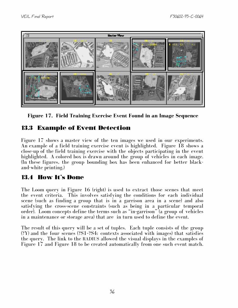
VEIL Final Report F30602–93–C–0064
36
13.3 Example of Event Detection
Figure 17 shows a master view of the ten images we used in our experiments.An example of a field training exercise event is highlighted. Figure 18 shows aclose-up of the field training exercise with the objects participating in the eventhighlighted. A colored box is drawn around the group of vehicles in each image.(In these figures, the group bounding box has been enhanced for better black-and-white printing.)
13.4 How It’s Done
The Loom query in Figure 16 (right) is used to extract those scenes that meetthe event criteria. This involves satisfying the conditions for each individualscene (such as finding a group that is in a garrison area in a scene) and alsosatisfying the cross-scene constraints (such as being in a particular temporalorder). Loom concepts define the terms such as “in-garrison” (a group of vehiclesin a maintenance or storage area) that are in turn used to define the event.
The result of this query will be a set of tuples. Each tuple consists of the group(?Y) and the four scenes (?S1–?S4: contexts associated with images) that satisfiesthe query. The link to the RADIUS allowed the visual displays in the examples ofFigure 17 and Figure 18 to be created automatically from one such event match.
Figure 17. Field Training Exercise Event Found in an Image Sequence

F30602–93–C–0064 VEIL Final Report
37
Because of Loom’s named definitions, the query for finding events is quitecompact and reasonably readable. This shows the power of having an extensibledomain-specific language: even complex criteria can be expressed in a concise andnatural manner.
14. Current Status
The current VEIL model has been tested using ten images from the RADIUS ModelBoard 2 image set (See Appendix B). It is integrated with the RCDE code and usesthe RCDE graphics interface for user interaction and display purposes. Thefigures in this report are screen shots from the VEIL-RCDE system.
Figure 18. Close-Up View of Field Training Exercise
VEIL Final Report F30602–93–C–0064
38
15. Future Work
There are several directions for extending our research. One major directionwould be to improve the matching algorithm used to find events. The currentmatch relies on using Loom’s general query mechanism. While this providesflexibility, the logic-based query language does not take advantage of specialfeatures of the problem of event matching that can increase efficiency. Forexample, there is no direct exploitation of the fact that the scenes being lookedfor form an ordered sequence. Additional enhancements would be to modify theevent matching language to allow inexact matches. This can take the form ofpartial matches, matches to key features but with missing elements, or a moregeneral probabilistic matching scheme.
A sub-problem of the general matching task is associating groups from one imagewith those from a different image. (In the current work, such matching is doneby hand.) An interim position would be to use a credulous matcher,4 althoughthat would need to be refined in order to scale well. The preferred approachwould be to develop a compatibility score for matches between groups in oneimage and groups in another image. This score would be based on factors such asthe size of the group, the composition of the group (i.e., with or without tanks),as well as heuristic reasoning based on other elements that are visible in animage. With a more sophisticated matcher, a list of candidate image sequencescan be identified and ranked as to the closeness of the match.
Computer support for assigning individual vehicles to groups is another area forfurther investigation. The group assignment problem involves identifying acollection of vehicle that are related in some interesting way. Geometricproximity is one important consideration, but it is not always he most important.Consider a convoy driving by a parking lot. Some vehicles in the convoy will becloser to parked vehicles than to other convoy vehicles, but the importance ofbeing on the road should be given more weight in the group assignment process.A semi-automated grouping tool would be a useful addition to RCDE.
4 A credulous matcher is one that would return all potential matches. This guarantees that no matches will be missed, but i slikely to return a lot of false positive matches.

F30602–93–C–0064 VEIL Final Report
39
Part IV.
Conclusion.
Vision programming tools are adequate for low-level vision processing, but lessappropriate for high-level vision tasks. This proposal offered a remedy for thissituation, namely, to use the Loom system to represent high-level visualknowledge. We employed a layered architecture wherein specialized datastructures were used to represent lower-level knowledge, while symbolicstructures were used to represent higher level knowledge.
VEIL was an experiment both to see how traditional knowledge representationtechnology can be applied to computer vision programs and to explore extensionsto knowledge representation systems to directly aid computer vision research(especially in the area of spatial reasoning and event detection.)
16. Representation in Programs
A key benefit of applying Loom knowledge representation technology to visionprocessing was that the VEIL system was able to use the semantic informationexpressed in Loom models to form expectations about the objects in the visualfield, and thereby guide the low-level vision routines. This improved the overallaccuracy and robustness of the vision system, in addition to easing systemdevelopment, and improving its maintainability and extensibility.
High level reasoning provided by Loom was integrated with low- and mid-levelprocessing techniques, such as line finding, segmentation, perceptual groupingand shape descriptions commonly used in vision systems. The goal of VEILdevelopment is to allow vision application systems to be written more easily, byenabling the construction of explicit declarative vision models, and by exploitingthe knowledge representation and reasoning capabilities provided by Loom. Theexperience with the airport example shows that this goal was achieved.
17. Domain Level Reasoning
The bulk of work in IU research has been on developing algorithms that operateat the pixel level and are able to recognize geometric objects. Common examplesare edge detectors, building detectors and vehicle detectors. In our work, wehave been investigating the next stage of image understanding. In other words,we are concerned with the question of what sort of processing would we like tohave happen once the low-level detectors have finished their work.
We feel that the next step involves reasoning with the aid of domain models—models of the world. This raises the level of abstraction of the interface between

VEIL Final Report F30602–93–C–0064
40
the image analyst and the computer system. Instead of operating at the level ofpixels or geometric shapes, one would like to have the interface operate at a levelthat has the appropriate semantic content for the task at hand. This level wouldallow interaction in terms of headquarters rather than buildings, convoys ratherthan isolated vehicles. By raising the level of interaction, better use of an imageanalyst’s time can be made.
By increasing the level of abstraction and allowing queries at that level, itbecomes easier to select appropriate images for viewing out of a large library. Byraising the level of abstraction, we are also able to describe events that covermultiple images naturally and locate them efficiently.

F30602–93–C–0064 VEIL Final Report
41
APPENDIX A
Image Understanding Environment Support
The Image Understanding Environment (IUE) in an object oriented softwaredevelopment system for supporting research in image understanding and forfacilitating the exchange of results and programs among different researchgroups. The IUE provides a conceptual framework for image understandingdescribing algorithms and data and the implementation of standard techniqueswithin the IUE will allow for performance evaluation and comparisons betweendifferent techniques.
The process of designing the IUE began in 1989 with a number of meetingswhere existing systems and approaches were evaluated and the goals of theprogram were specified. In 1991, the IUE Technical Committee (IUETC) wasestablished to generate the final specifications. This design process resulted in adesign with over 500 classes and over 800 pages of documentation. Theimplementation effort is led by AAI, but the initial class definitions and emptymethod definitions are generated directly from the documentation that wasdeveloped by the IUETC in its several years of effort. We participated in theinitial evaluation effort and in the later specification and evaluation effort whileserving on the IUETC.
In the initial specification phase of the project our primary role was in thedescription of image features, the spatial index and data exchange. While theimplementation of the basic IUE is being done by AAI, a number of programs(called the library) are not included in their requirements.
Our role in this design process included work on the general specifications,through the many meetings of the committee. We provided detailedspecifications in the area of image features, the spatial index, and data exchange.Image features are the primary building blocks of image understandingprograms. These include point (0-D) features such as simple edge elements, line(1-D) features such as extracted edge or line features, and area (2-D) featuressuch as image regions, and groupings of these basic features such as linejunctions and ribbon features.
In the development of the IUE, the initial specification of image features wastreated separately from other objects (indeed the initial specification of manyparts was separate from other related objects). Through the committeediscussions it became apparent that the general group of spatial objects and imagefeatures were similar, but different. This led to the development of the currentimage feature description in terms of the more general spatial object hierarchy.In many cases the only difference between an image feature and thecorresponding spatial object is the relationship of the feature to an image.

VEIL Final Report F30602–93–C–0064
42
We developed programs to extract edge elements from the image, group theedges into sequences, extract image-feature line segments from the sequences,and finally to group the line segments into parallel pairs (for simple ribbonfeatures). These programs were based on the earlier work of Nevatia and Babu[Nevatia and Babu 1980].
For many operations it is necessary to answer a variety of spatial questions aboutan object. For example “what line segments are near some point?” or “what linesegments are within a given distance from a line?” The typical storage of the linesegment feature in a list works when there are few features, but results in largecomputation times for images typically used in many applications (which caneasily have 10,000 or 50,000 line segments). To efficiently answer thesequestions, we use a spatial index. In the simplest form, this is just an array thatmaps directly to image locations (usually the array is smaller than the image sothat blocks of the image map to one array location). This means that spatialquestions (e.g. near a point, near a line, etc.) can be approximately answered byreference to the array, with exact answers still requiring testing of the limitednumber of objects that are returned from the array reference. The basic spatialindex design was completed with the implementation being done by AAI undertheir IUE implementation contract.
One of the early goals of the IUE was predictable data exchange of structuresnormally used by image understanding programs. For this purpose, the IUEcommittee defined an IUE data exchange standard. The standard must befunctional (able to describe all objects), compatible, portable and extensible. Weadopted a character-based, human readable format that uses a Lisp-like syntax(primarily the use of parentheses as delimiters) with generic representations.The data exchange standard thus provides a means for transfer between users ofthe IUE, but also provides a means to transfer data, with consistent interpretationof the values, between the IUE and other systems or between different imageanalysis systems.
While AAI implemented the IUE DEX system, we implemented a Lisp-Based DEXreader/writer so that data could be exchanged between the IUE and the RCDEused in the program.
To support the goal of providing working programs in the IUE and to test thecompleteness of image feature descriptions we developed programs to extractedge elements from the image, group the edges into sequences, extract image-feature line segments from the sequences, and finally to group the line segmentsinto parallel pairs (for simple ribbon features). These programs were based onthe earlier work of Nevatia and Babu [Nevatia and Babu 1980]. The initialimplementation of these programs came before many of the image feature classeswere implemented, but the transition to the later versions of the IUE wassimplified by using the same basic descriptions of the objects (since the enhancedcapabilities that come with the IUE objects were not needed).

F30602–93–C–0064 VEIL Final Report
43
APPENDIX B
Model Board 2 Images
Figure 19. Map of Model Board 2

VEIL Final Report F30602–93–C–0064
44
Figure 20. Image M 4

F30602–93–C–0064 VEIL Final Report
45
Figure 21. Image M 6

VEIL Final Report F30602–93–C–0064
46
Figure 22. Image M 8

F30602–93–C–0064 VEIL Final Report
47
Figure 23. Image M12

VEIL Final Report F30602–93–C–0064
48
Figure 24. Image M16

F30602–93–C–0064 VEIL Final Report
49
Figure 25. Image M19

VEIL Final Report F30602–93–C–0064
50
Figure 26. Image M24

F30602–93–C–0064 VEIL Final Report
51
Figure 27. Image M27

VEIL Final Report F30602–93–C–0064
52
Figure 28. Image M32

F30602–93–C–0064 VEIL Final Report
53
Figure 29. Image M33


F30602–93–C–0064 VEIL Final Report
55
APPENDIX C
Vehicle Location Data
These tables contain theinformation that wasused to augment the sitemodels provided withthe RADIUS distribution.
Since the project did nothave a reliable vehicledetector available, thevehicle locations, vehicletypes and vehicle groupassignments were doneby humans.
The VEIL program usedthe group and locationinformation to infer thestatus of groups as beingin convoys, in garrisonareas or in the field. Ascan be seen, the onlysemantic content addedby hand are vehicle typeand group assignments.VEIL automatically infersall additional semanticinformation.
Coordinates are given interms of the underlyingRADIUS Model Board 2site model’s geographiccoordinate system. Theycan be used by Otherresearchers using thissite model.
Image M 4Group Type X Y
None Crane 1407.0 -352.3Crane 1412.7 -235.8
Vehicle 1413.7 -468.3Vehicle 1448.1 -350.0Vehicle 1448.4 -373.7Vehicle 1457.2 -439.5Vehicle 1470.3 -112.5Vehicle 1481.9 76.7
Group 1 Vehicle 705.8 714.1Vehicle 740.8 716.6
Tank 775.6 738.5Tank 786.9 774.9Tank 809.7 828.2Tank 832.5 871.6Tank 846.7 902.9Tank 863.6 946.3Tank 892.1 979.7Tank 943.7 972.0Tank 986.7 950.0Tank 1032.3 923.3
Vehicle 1249.3 815.0Group 3 Vehicle 1437.2 718.3
Tank 1540.7 933.4Vehicle 1553.8 966.0
Image M 6Group Type X Y
Group 1 Tank -142.1 352.5Tank -138.2 313.1Tank -135.5 400.8Tank -133.0 274.9Tank -129.4 242.9Tank -128.5 436.7Tank -109.5 472.7Tank -93.1 508.7Tank -67.3 539.8Tank -43.7 556.0Tank -24.2 573.4Tank -18.7 615.3
SP-Artillery 34.4 349.0SP-Artillery 48.9 395.9SP-Artillery 59.9 429.2
Vehicle 75.6 1029.3Vehicle 118.6 95.9Vehicle 121.7 125.3Vehicle 125.0 1061.0Vehicle 137.7 119.5Vehicle 155.5 1106.2Vehicle 171.0 381.7Vehicle 254.3 1012.3Vehicle 293.9 490.7Vehicle 303.5 521.2Vehicle 313.0 321.7Vehicle 333.1 351.2Vehicle 358.5 374.7Vehicle 381.2 398.1Vehicle 404.1 416.6Vehicle 426.7 1008.9Vehicle 442.1 1014.9Vehicle 459.9 1025.7Vehicle 474.6 961.2
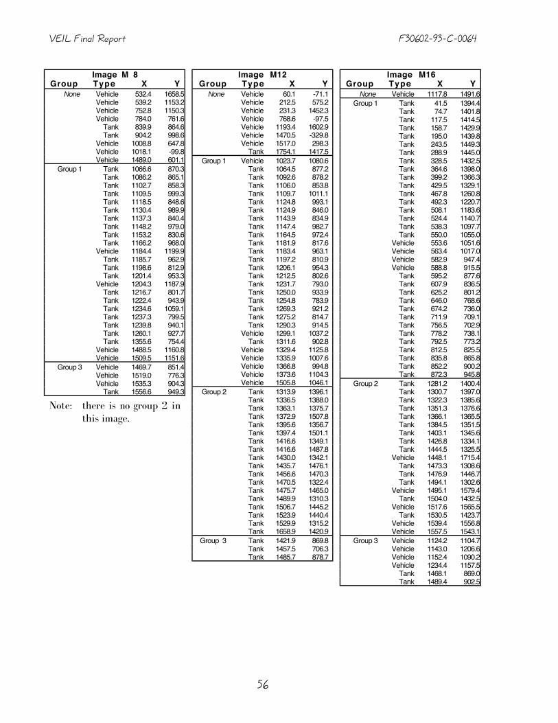
VEIL Final Report F30602–93–C–0064
56
Image M 8Group Type X Y
None Vehicle 532.4 1658.5Vehicle 539.2 1153.2Vehicle 752.8 1150.3Vehicle 784.0 761.6
Tank 839.9 864.6Tank 904.2 998.6
Vehicle 1008.8 647.8Vehicle 1018.1 -99.8Vehicle 1489.0 601.1
Group 1 Tank 1066.6 870.3Tank 1086.2 865.1Tank 1102.7 858.3Tank 1109.5 999.3Tank 1118.5 848.6Tank 1130.4 989.9Tank 1137.3 840.4Tank 1148.2 979.0Tank 1153.2 830.6Tank 1166.2 968.0
Vehicle 1184.4 1199.9Tank 1185.7 962.9Tank 1198.6 812.9Tank 1201.4 953.3
Vehicle 1204.3 1187.9Tank 1216.7 801.7Tank 1222.4 943.9Tank 1234.6 1059.1Tank 1237.3 799.5Tank 1239.8 940.1Tank 1260.1 927.7Tank 1355.6 754.4
Vehicle 1488.5 1160.8Vehicle 1509.5 1151.6
Group 3 Vehicle 1469.7 851.4Vehicle 1519.0 776.3Vehicle 1535.3 904.3
Tank 1556.6 949.3
Note: there is no group 2 in this image.
Image M12Group Type X Y
None Vehicle 60.1 -71.1Vehicle 212.5 575.2Vehicle 231.3 1452.3Vehicle 768.6 -97.5Vehicle 1193.4 1602.9Vehicle 1470.5 -329.8Vehicle 1517.0 298.3
Tank 1754.1 1417.5Group 1 Vehicle 1023.7 1080.6
Tank 1064.5 877.2Tank 1092.6 878.2Tank 1106.0 853.8Tank 1109.7 1011.1Tank 1124.8 993.1Tank 1124.9 846.0Tank 1143.9 834.9Tank 1147.4 982.7Tank 1164.5 972.4Tank 1181.9 817.6Tank 1183.4 963.1Tank 1197.2 810.9Tank 1206.1 954.3Tank 1212.5 802.6Tank 1231.7 793.0Tank 1250.0 933.9Tank 1254.8 783.9Tank 1269.3 921.2Tank 1275.2 814.7Tank 1290.3 914.5
Vehicle 1299.1 1037.2Tank 1311.6 902.8
Vehicle 1329.4 1125.8Vehicle 1335.9 1007.6Vehicle 1366.8 994.8Vehicle 1373.6 1104.3Vehicle 1505.8 1046.1
Group 2 Tank 1313.9 1396.1Tank 1336.5 1388.0Tank 1363.1 1375.7Tank 1372.9 1507.8Tank 1395.6 1356.7Tank 1397.4 1501.1Tank 1416.6 1349.1Tank 1416.6 1487.8Tank 1430.0 1342.1Tank 1435.7 1476.1Tank 1456.6 1470.3Tank 1470.5 1322.4Tank 1475.7 1465.0Tank 1489.9 1310.3Tank 1506.7 1445.2Tank 1523.9 1440.4Tank 1529.9 1315.2Tank 1658.9 1420.9
Group 3 Tank 1421.9 869.8Tank 1457.5 706.3Tank 1485.7 878.7
Image M16Group Type X Y
None Vehicle 1117.8 1491.6Group 1 Tank 41.5 1394.4
Tank 74.7 1401.8Tank 117.5 1414.5Tank 158.7 1429.9Tank 195.0 1439.8Tank 243.5 1449.3Tank 288.9 1445.0Tank 328.5 1432.5Tank 364.6 1398.0Tank 399.2 1366.3Tank 429.5 1329.1Tank 467.8 1260.8Tank 492.3 1220.7Tank 508.1 1183.6Tank 524.4 1140.7Tank 538.3 1097.7Tank 550.0 1055.0
Vehicle 553.6 1051.6Vehicle 563.4 1017.0Vehicle 582.9 947.4Vehicle 588.8 915.5
Tank 595.2 877.6Tank 607.9 836.5Tank 625.2 801.2Tank 646.0 768.6Tank 674.2 736.0Tank 711.9 709.1Tank 756.5 702.9Tank 778.2 738.1Tank 792.5 773.2Tank 812.5 825.5Tank 835.8 865.8Tank 852.2 900.2Tank 872.3 945.8
Group 2 Tank 1281.2 1400.4Tank 1300.7 1397.0Tank 1322.3 1385.6Tank 1351.3 1376.6Tank 1366.1 1365.5Tank 1384.5 1351.5Tank 1403.1 1345.6Tank 1426.8 1334.1Tank 1444.5 1325.5
Vehicle 1448.1 1715.4Tank 1473.3 1308.6Tank 1476.9 1446.7Tank 1494.1 1302.6
Vehicle 1495.1 1579.4Tank 1504.0 1432.5
Vehicle 1517.6 1565.5Tank 1530.5 1423.7
Vehicle 1539.4 1556.8Vehicle 1557.5 1543.1
Group 3 Vehicle 1124.2 1104.7Vehicle 1143.0 1206.6Vehicle 1152.4 1090.2Vehicle 1234.4 1157.5
Tank 1468.1 869.0Tank 1489.4 902.5

F30602–93–C–0064 VEIL Final Report
57
Image M19Group Type X Y
Group 1 Tank 589.1 928.4Vehicle 606.3 870.4Vehicle 647.8 772.8Vehicle 674.1 742.9Vehicle 701.6 716.1Vehicle 730.8 687.5Vehicle 771.6 724.1
Tank 799.4 793.1Tank 821.9 835.7Tank 843.5 880.7Tank 869.8 941.9Tank 940.6 1077.6
Group 2 Tank 1462.1 602.7Tank 1481.9 646.1Tank 1500.8 682.7Tank 1508.4 594.3Tank 1513.5 720.9Tank 1536.4 762.4Tank 1552.8 595.0Tank 1558.4 804.5
Vehicle 1582.9 851.4Tank 1600.5 600.0Tank 1643.7 609.0Tank 1686.7 619.7Tank 1730.3 633.4Tank 1770.3 652.0Tank 1809.4 663.9Tank 1843.8 687.0Tank 1881.4 712.5
Vehicle 1911.5 730.2Vehicle 1938.2 743.6Vehicle 1965.5 761.7Vehicle 2002.8 781.4
Group 3 Tank 959.0 964.3Tank 1040.5 1053.8Tank 1106.4 886.9Tank 1205.4 840.2Tank 1249.9 779.5
Vehicle 1374.2 735.9Tank 1413.8 871.1Tank 1450.2 706.2Tank 1473.3 881.1
Group 4 Tank 1286.0 1404.5Tank 1303.9 1395.5Tank 1327.7 1388.1Tank 1350.6 1376.3Tank 1478.0 1311.1Tank 1493.9 1439.1Tank 1507.4 1433.9Tank 1516.8 1316.5
Image M24Group Type X Y
Group 1 Vehicle 573.6 -108.0Vehicle 617.1 -111.0Vehicle 628.4 809.3
Tank 1036.0 887.5Tank 1055.0 874.4
Vehicle 1065.0 -137.0Tank 1075.0 866.1Tank 1090.0 857.8Tank 1091.0 1005.0Tank 1110.0 849.6Tank 1113.0 998.7Tank 1124.0 838.9Tank 1130.0 990.3Tank 1143.0 829.5Tank 1146.0 984.4Tank 1163.0 974.8Tank 1164.0 820.1Tank 1181.0 811.9Tank 1183.0 963.0Tank 1199.0 802.6Tank 1200.0 951.1Tank 1219.0 944.0Tank 1219.0 792.0Tank 1233.0 936.9Tank 1242.0 781.5Tank 1253.0 926.3Tank 1269.0 915.6Tank 1291.0 908.6Tank 1306.0 899.2
Vehicle 1498.0 568.8Vehicle 1504.0 281.4Vehicle 1505.0 194.6
Tank 1537.0 946.9Vehicle 1539.0 596.4
Image M27Group Type X Y
None Vehicle 155.4 1441Vehicle 169.8 -80.1Vehicle 525.7 1164.2Vehicle 755.0 1407.6Vehicle 904.9 1029.9Vehicle 1017.7 -94.5Vehicle 1468.1 640.4
Group 1 Tank 1053.7 874.3Tank 1079.1 866.6Tank 1093.4 860.0Tank 1101.0 1000.9Tank 1110.5 850.9Tank 1121.8 993.7Tank 1128.9 845.1Tank 1138.7 984.5Tank 1146.5 833.1Tank 1156.0 973.9
Vehicle 1171.1 1198.3Tank 1176.6 966.8Tank 1191.5 812.5Tank 1191.8 955.9
Vehicle 1195.7 1191.5Tank 1208.7 802.1Tank 1211.7 951.8Tank 1223.0 1065.1Tank 1228.9 796.7Tank 1231.5 938.7Tank 1253.9 932.0Tank 1346.6 756.8
Vehicle 1476.9 1163.7Vehicle 1501.9 1151.5
Group 2 Tank 1293.8 1401.9Tank 1314.0 1394.4Tank 1339.4 1381.8Tank 1356.6 1536.1Tank 1364.1 1372.0Tank 1375.6 1524.0Tank 1376.5 1362.1Tank 1397.5 1350.4Tank 1402.1 1514.3Tank 1449.9 1350.5
Vehicle 1465.5 1483.4Vehicle 1487.8 1473.3
Tank 1507.5 1335.5Vehicle 1513.2 1457.9Vehicle 1542.4 1443.1
Tank 1576.5 1561.4Tank 1617.2 1529.3
Group 3 Vehicle 1457.9 851.8Tank 1550.4 949.7Tank 1570.9 991.0
Group 4 Vehicle 1720.2 1250.0Tank 1827.9 1552.6Tank 1846.4 1538.0
Group 5 Tank 2087.8 529.3Vehicle 2088.7 285.2Vehicle 2090.0 321.0
Tank 2090.0 502.8Vehicle 2090.1 304.0
Tank 2150.6 549.3Tank 2168.1 382.2Tank 2169.4 409.3Tank 2169.6 433.4Tank 2169.8 309.0Tank 2170.0 333.1Tank 2170.1 357.2Tank 2170.9 452.0

VEIL Final Report F30602–93–C–0064
58
Image M32Group Type X Y
None Vehicle 207.8 578.7Group 1 Vehicle -93.1 1379.5
Vehicle -59.0 1386.7Vehicle -21.6 1395.5Vehicle 9.6 1403.2Vehicle 46.4 1408.6Vehicle 87.2 1417.8Vehicle 121.3 1428.3Vehicle 166.4 1440.0Vehicle 207.3 1452.4Vehicle 243.2 1464.7
Tank 283.7 1461.0Tank 323.5 1442.5Tank 358.4 1417.1Tank 387.7 1388.3Tank 415.4 1355.5Tank 443.6 1319.3Tank 462.9 1285.0Tank 485.0 1248.0Tank 502.6 1209.9
Vehicle 525.6 1156.4Vehicle 571.2 986.7Vehicle 577.8 954.9Vehicle 589.8 913.5Vehicle 602.8 873.2Vehicle 620.2 834.4
Tank 643.9 787.2Tank 669.1 749.7Tank 705.6 719.0Tank 753.4 712.0Tank 779.2 768.4Tank 802.6 819.9Tank 828.9 868.9Tank 853.2 916.1Tank 886.9 974.7Tank 934.2 980.0
Vehicle 990.5 953.5Group 2 Vehicle 990.0 646.1
Tank 1025.8 641.2Tank 1067.9 637.3Tank 1110.3 631.3Tank 1160.9 621.8Tank 1212.3 612.2Tank 1260.7 605.2Tank 1310.8 599.9Tank 1348.9 599.7Tank 1403.5 596.7Tank 1456.4 596.0Tank 1502.2 597.5Tank 1503.3 597.3Tank 1551.2 597.4Tank 1596.8 603.9Tank 1640.1 610.7Tank 1682.4 622.7Tank 1724.7 633.7
Vehicle 1760.3 646.7Vehicle 1801.4 663.8Vehicle 1829.5 677.1Vehicle 1862.5 699.5
Image M32 (continued)Group Type X Y
Group 3 Vehicle 1293.5 1043.1Tank 1413.0 872.6Tank 1449.8 708.0Tank 1471.8 884.7
Vehicle 1498.4 1050.2
Group 4 Tank 1282.0 1417.3Tank 1300.6 1406.8Tank 1319.9 1398.3Tank 1347.6 1385.8Tank 1474.5 1318.5Tank 1490.0 1450.3Tank 1506.0 1446.8Tank 1515.8 1327.1
Group 5 Tank 2094.8 473.0Tank 2095.7 443.5Tank 2096.8 503.2
Image M33Group Type X Y
None Vehicle 1125.1 625.8Group 1 Vehicle 244.5 1453.6
Vehicle 298.1 1451.2Vehicle 343.4 1429.8Vehicle 380.8 1391.8Vehicle 419.7 1348.9Vehicle 437.5 1317.9
Tank 462.9 1277.2Tank 486.4 1238.9Tank 505.3 1200.5Tank 526.9 1164.5Tank 535.7 1121Tank 544.8 1079.8Tank 555.9 1036Tank 572.4 982.4Tank 583.6 938.4
Vehicle 603.3 874.7Vehicle 654.1 771.5Vehicle 675.9 747.1Vehicle 704.4 720.3Vehicle 732.5 691.0Vehicle 777.2 734.4
Tank 799.0 796.8Tank 827.2 841.7Tank 843.2 883.7Tank 873.5 942.9Tank 939.2 1081.7Tank 960.1 966.1Tank 1250.4 781.4Tank 1280.6 915.4Tank 1301.5 903.7Tank 1409.3 869.4Tank 1448.2 705.1
Group 2 Tank 1284.0 1411.7Tank 1308.9 1400.1Tank 1327.5 1390.9Tank 1349.8 1517.5Tank 1354.9 1381.7Tank 1372.7 1508.3Tank 1373.5 1372.5Tank 1388.9 1356.3Tank 1393.0 1496.8Tank 1410.6 1354.0Tank 1413.6 1487.6Tank 1429.9 1478.4Tank 1430.4 1337.9Tank 1449.0 1328.7Tank 1452.7 1469.3Tank 1473.0 1457.8Tank 1477.9 1314.9Tank 1493.6 1448.6Tank 1501.4 1310.3Tank 1507.4 1437.2Tank 1528.3 1430.3
Vehicle 1569.0 1557.8Vehicle 1593.4 1546.4Vehicle 1621.6 1530.5

F30602–93–C–0064 VEIL Final Report
59
BBBBiiiibbbblllliiiiooooggggrrrraaaapppphhhhyyyy
[Abella 1995] Alicia Abella., From Imagery to Salience: Locative Expressions inContext, Ph.D. thesis, Columbia University, 1995.
[Bonissone et al 1987]. Piero Bonissone, Stephen Gans, and Keith Decker, “RUM:A Layered Architecture for Reasoning with Uncertainty,” in Proceedings of the10th International Joint Conference on Artificial Intelligence, pp. 891-898,AAAI, August 1987.
[Brachman 1979] Ronald J. Brachman, On the Epistemological Status of SemanticNetworks, pages 3–50, 1979. (Reprinted in Ronald J. Brachman and Hector J.Levesque, editors. Readings in Knowledge Representation, Morgan KaufmannPublishers, Inc., Los Altos, CA, 1985. pp. 192–215)
[Brachman et al. 1983] Ronald J. Brachman, Richard E. Fikes, and Hector J.Levesque, KRYPTON: A functional approach to knowledge representation, IEEEComputer, 16(10):67–73, 1983. (Revised version reprinted in Ronald J.Brachman and Hector J. Levesque, editors. Readings in KnowledgeRepresentation, Morgan Kaufmann Publishers, Inc., Los Altos, CA, 1985., pp.412–429.)
[Brill 1993] David Brill, Loom Reference Manual, Version 2.0, USC/ISI, 4676Admiralty Way, Marina del Rey, CA 90292, December 1993.
[Burhans et al. 1994] Debra Burhans, Rajiv Chopra, Rohini K. Srihari,Venugopal Govindaraju, and Mahesh Venkataraman, Use of Collateral Text inImage Interpretation, Proceedings of the ARPA Image Understanding Workshop,Morgan Kaufmann Publishers, Inc. pp. 897–907, 1994.
[Canny 1986] J.F. Canny, “A computational approach to edge detection,” IEEETransactions on Pattern Recognition and Machine Intelligence, Vol. 8, No. 6, pp.679-698, November 1986.
[Collins et al. 1989] R. Collins, J. Brolio, A. Hanson, and E. Riseman, “TheSchema System,” International Journal of Computer Vision, Vol. 2, No. 3, pp.209-250, 1989.
[Draper et al. 1989] B. A. Draper, R. T. Collins, J. Brolio, A. R. Hanson and E. M.Riseman, “The Schema System,” in International Journal of Computer Vision,Vol. 2, 1989, pp. 209-250.

VEIL Final Report F30602–93–C–0064
60
[Faugeras et al. 1981] O. Faugeras and K. Price, “Symbolic Description of AerialImages using Stochastic Labeling,” in IEEE Transactions on PAMI, Vol.3, pp633-642, November 1981.
[Haarslev et al. 1994] Volker Haarslev, Ralf Möller and Carsten Schröder,Combining Spatial and Terminological Reasoning, KI–94: Advances in ArtificialIntelligence — Proceedings of the 18th German Annual Conference in ArtificialIntelligence, published as Lecture Notes in Artificial Intelligence, vol. 891(Springer-Verlag: Berlin), pp. 142–153, 1994.
[Huertas and Nevatia 1988] A. Huertas and R. Nevatia, “Detecting Buildings inAerial Images,” in Computer Vision, Graphics and Image Processing Journal,No.41, pp 131-152, 1988.
[Huertas et al 1989] A. Huertas, W. Cole, and R. Nevatia, “Using GenericKnowledge in Analysis of Aerial Scenes: A Case Study,” in Proceedings 10thInternational Joint Conference on Artificial Intelligence, Detroit, Michigan,August 1989.
[Huertas et al 1990] A. Huertas, W. Cole, and R. Nevatia, “Detection ofRunways in Complex Airport Scenes,” in Computer Vision, Graphics and ImageProcessing Journal, No.51, pp 107-145, 1990.
[MacGregor 1988] MacGregor, Robert, “A Deductive Pattern Matcher,” inProceedings of AAAI-88, The National Conference on Artificial Intelligence,1988a.
[MacGregor 1990] Robert MacGregor “LOOM Users Manual,” in USC/ISITechnical Report, ISI/WP-22, 1990a.
[MacGregor 1990] Robert MacGregor “The Evolving Technology ofClassification-based Knowledge Representation Systems,” to appear in Principlesof Semantic Networks: Explorations in the Representation of Knowledge, JohnSowa, Ed., Morgan-Kaufman, 1990b.
[MacGregor and Bates 1987], Robert MacGregor and Raymond Bates, The Loomknowledge repre-sentation language, Technical Report ISI/RS–87–188, USCInformation Sciences Institute, 1987.
[MacGregor and Burstein 1991] R. MacGregor and M. Burstein, “Using aDescription Classifier to Enhance Knowledge Representation,” IEEE Expert, Vol6, No. 3, pages 41-46, June 1991.
[MacGregor and Yen 1988] Robert MacGregor and John Yen, “The KnowledgeRepresentation Project at ISI,” in USC/ISI Technical Report, RR-87-199,1988b.

F30602–93–C–0064 VEIL Final Report
61
[McKeown et al. 1985] D. M. McKeown, Jr., W. A. Harvey, and J. McDermott,“Rule Based Interpretation of Aerial Imagery,” IEEE Transactions on PatternAnalysis and Machine Intelligence, Vol 7, No. 5, September. 1985, pp. 570-585.
[McKeown 1989] D. M McKeown., W. A. Harvey and L. E. Wikson, “AutomatingKnowledge Acquisition for Aerial Image Interpretation,” in Computer Vision,Graphics and Image Processing, Vol 46, 1989, pp. 37-81.
[Medioni et al. 1984] G. Medioni, and R. Nevatia, “Matching Images Using LinearFeatures,” in IEEE Transactions on PAMI, Vol.6, No.6, November 1984.
[Mohan 1989] R. Mohan and R. Nevatia, “Using Perceptual Organization toExtract 3-D Structures,” in IEEE Transactions on PAMI, Vol 11, No. 11,November 1989.
[Mundy et al. 1993] J. Mundy and The Gang of Ten, “The Image UnderstandingEnvironment: Overview,” in Proc. ARPA Image Understanding Workshop,Washington, DC, April 1993, pp. 283-288.
[Nevatia and Babu 1980] R. Nevatia and K. R. Babu, “Linear Feature Extractionand Description,” Comp. Graphics and Image Processing, Vol. 13, 1980, pp. 257–269.
[Nevatia and Price 1982] R. Nevatia, and K. Price. “Locating Structures in AerialImages,” in IEEE Transactions on PAMI, Vol.4, No.5, Sepember 1982.
[Payton 1984] D. W. Payton, “A symbolic pixel array representation of spatialknowledge,” in Proceedings of the IEEE Conference of Computers andCommunications, Phoenix, 1984, pp. 11-16]
[Price et al. 1994] Keith Price, Thomas Russ, and Robert MacGregor, Knowledgerepresentation for computer vision: The VEIL project, Proceedings of the ARPAImage Understanding Workshop, Morgan Kaufmann, pp. 919–927, 1994.
[RADIUS Manual 1993], SRI International and Martin Marietta, RADIUSCommon Development Environment: Programmer’s Reference Manual, version 1.0edition, July 1993.
[Silberberg 1987] T. Silberberg, “Context Dependent Target Recognition”, inProceedings of the Image Understanding Workshop, Los Angeles, 1987, pp. 313-320.
[Srihari et al. 1996] R. K. Srihari, Z. Zhang, M. Venkatraman, R. Chopra, ,Usingspeech input for image interpretation and annotation, Proceedings of the ARPAImage Understanding Workshop, Morgan Kaufmann, pp. 501–510, 1996.

VEIL Final Report F30602–93–C–0064
62
[Winston 1975] P. H. Winston, “Learning Structural Descriptions fromExamples,” in The Psychology of Computer Vision, P. H. Winston, Ed., NewYork:McGraw Hill, 1975, Chapter 5.
[Yen et al. 1989] John Yen, Robert Neches, and Robert MacGregor, “UsingTerminological Models to Enhance the Rule-based Paradigm,” in Proceedings ofthe Second International Symposium on Artificial Intelligence, Monterrey,Mexico, October 1989.