vectra-tsynthes.vo.llnwd.net/o16/llnwmb8/int mobile/synthes... · · 2016-08-04this publication...
TRANSCRIPT

The Translational Anterior Cervical Palate System
VECTRA-T
This publication is not intended for distribution in the USA.
SURGICAL TECHNIQUE

Image intensifier control
This description alone does not provide sufficient background for direct use of DePuy Synthes products. Instruction by a surgeon experienced in handling these products is highly recommended.
Processing, Reprocessing, Care and MaintenanceFor general guidelines, function control and dismantling of multi-part instruments, as well as processing guidelines for implants, please contact your local sales representative or refer to:http://emea.depuysynthes.com/hcp/reprocessing-care-maintenanceFor general information about reprocessing, care and maintenance of Synthes reusable devices, instrument trays and cases, as well as processing of Synthes non-sterile implants, please consult the Important Information leaflet (SE_023827) or refer to: http://emea.depuysynthes.com/hcp/reprocessing-care-maintenance

Vectra-T The Translational Anterior Cervical Palate System Surgical Technique DePuy Synthes 1
Table of Contents
Introduction Vectra-T 2
AO Principles 5
Indications and Contraindications 6
Product Information Implants 7
Vario Case 11
Instruments 12
Surgical Technique Implant Selection and Preparation 16
Option A: Awl and Self-Drilling Variable Angle Screws 19
Option B: Drill Sleeves and Self-Tapping Screws 22
Option C: Drill and Screw Guide 26
Implant Removal 30

2 DePuy Synthes Vectra-T The Translational Anterior Cervical Palate System Surgical Technique
brown 4.0 mm aqua 4.5 mm
14° range 7° offset 8° offset
Fixed angle screws – Cephalad/caudal: offset of 8° – Medial/lateral: offset of 7°
Medial/lateral angulation Cephalad/caudal angulation
Vectra-T. The Translational Anterior Cervical Plate System
Plates – Integrated blocking mechanism – Prelordosed – Large graft visibility window – 19 mm wide and 2.5 mm thin – Titanium alloy plate (TAN) – Integral Elgiloy clips lock the screws
to the plate
Screws – Screws are color coded to identify
function and diameter1 – Regular screw diameter 4.0 mm – Each screw type is also available
with diameter 4.5 mm for revision or where higher purchase is required
1 Self-drilling screws shown, same color code applies to self-tapping screws

Vectra-T The Translational Anterior Cervical Palate System Surgical Technique DePuy Synthes 3
blue 4.5 mm purple 4.0 mm
28° range
Variable angle screws – Cephalad/caudal 28° range – Medial/lateral 14° range
4 DePuy Synthes Vectra-T The Translational Anterior Cervical Palate System Surgical Technique
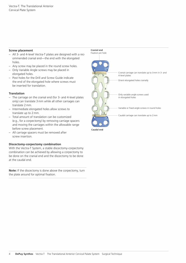
Screw placement – All 3- and 4-level Vectra-T plates are designed with a rec-
ommended cranial end—the end with the elongated holes.
– Any screw may be placed in the round screw holes. – Only Variable Angle screws may be placed in
elongated holes. – Post holes for the Drill and Screw Guide indicate
the end of the elongated hole where screws must be inserted for translation.
Translation – The carriage on the cranial end (for 3- and 4-level plates
only) can translate 3 mm while all other carriages can translate 2 mm.
– Intermediate elongated holes allow screws to translate up to 2 mm.
– Total amount of translation can be customized (e.g., for a corpectomy) by removing carriage spacers and moving the carriages within the allowable range before screw placement.
– All carriage spacers must be removed after screw insertion.
Discectomy-corpectomy combinationWith the Vectra-T System, a stable discectomy-corpectomy combination can be achieved by allowing a corpectomy to be done on the cranial end and the discectomy to be done at the caudal end.
Note: If the discectomy is done above the corpectomy, turn the plate around for optimal fixation.
Cranial carriage can translate up to 3 mm in 3- and 4-level plates
Orient elongated holes cranially
Only variable angle screws used in elongated holes
Variable or fixed angle screws in round holes
Caudal carriage can translate up to 2 mm
Caudal end
Cranial endFixation pin hole
Vectra-T. The Translational Anterior Cervical Plate System

Vectra-T The Translational Anterior Cervical Palate System Surgical Technique DePuy Synthes 5
AO Principles
In 1958, the AO formulated four basic principles, which have become the guidelines for internal fixation.1 They are:
Anatomic reduction – Plates are available in multiple lengths to allow proper
reduction of the vertebral column – Prelordosed plates restore lordotic curvature of the cervi-
cal spine
Stable internal fixation – Stabilizes the motion segment – Protects against excessive loads – Allows load transmission through graft to facilitate fusion
(Wolff’s Law)
Atraumatic surgical technique – Instrumentation designed for a minimal incision
Early, pain-free mobilization – The added stability of the plate enables earlier mobiliza-
tion of the cervical spine while providing an optimal envi-ronment for fusion.
1 Müller ME, Allgöwer M, Schneider R, Willenegger (1991) Manual of Internal Fixation. 3rd ed. Berlin Heidelberg New York: Springer
6 DePuy Synthes Vectra-T The Translational Anterior Cervical Palate System Surgical Technique
Indications and Contraindications
IndicationsThe Vectra-T System is intended for anterior plate and screw fixation of the cervical spine (C2–C7) for the following indi-cations: – Degenerative disc disease (DDD, defined as neck pain of
discogenic origin with degeneration of the disc confirmed by history and radiographic studies)
– Spondylolisthesis – Spinal stenosis – Tumors (primary and metastatic) – Failed previous fusions – Pseudarthrosis – Deformity (i.e kyphosis, lordosis and/or scolosis)
Contraindications – Severe osteoporosis – Any indication where fusion is not required
Note for long spans or poor bone quality: The surgeon is urged to consider the nature of such cases. The treatment may require the use of screws longer than 16 mm, and/or posterior fixation for this kind of inherently unstable case.
Vectra-T The Translational Anterior Cervical Palate System Surgical Technique DePuy Synthes 7
Implants
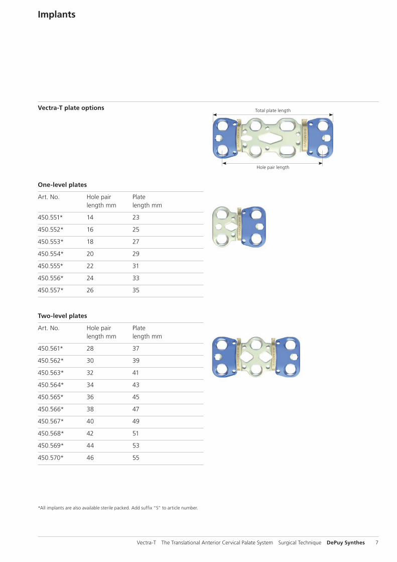
One-level plates
Art. No. Hole pair Plate length mm length mm
450.551* 14 23
450.552* 16 25
450.553* 18 27
450.554* 20 29
450.555* 22 31
450.556* 24 33
450.557* 26 35
Two-level plates
Art. No. Hole pair Plate length mm length mm
450.561* 28 37
450.562* 30 39
450.563* 32 41
450.564* 34 43
450.565* 36 45
450.566* 38 47
450.567* 40 49
450.568* 42 51
450.569* 44 53
450.570* 46 55
Vectra-T plate options Total plate length
Hole pair length
* All implants are also available sterile packed. Add suffix “S” to article number.

8 DePuy Synthes Vectra-T The Translational Anterior Cervical Palate System Surgical Technique
Four-level plates
Art. No. Hole pair Plate length mm length mm
450.581* 60 69
450.582* 64 73
450.583* 68 77
450.584* 72 81
450.585* 76 85
450.586* 80 89
450.587* 84 93
450.588* 88 97
450.589* 92 101
450.590* 96 105
450.591* 100 109
Implants
Three-level plates
Art. No. Hole pair Plate length mm length mm
450.571* 45 54
450.572* 48 57
450.573* 51 60
450.574* 54 63
450.575* 57 66
450.576* 60 69
450.577* 63 72
450.578* 66 75
450.579* 69 78
* All implants are also available sterile packed. Add suffix “S” to article number.

Vectra-T The Translational Anterior Cervical Palate System Surgical Technique DePuy Synthes 9
Vectra-T screw options
– Variable angle screws (purple and blue) – Fixed angle screws (brown and aqua) – Regular screw diameter 4.0 mm – Each screw type is also available with diameter 4.5 mm
for revision or where higher purchase is required – Monocortical screw lengths range from 12–18 mm
(self-drilling and self-tapping cancellous screws) – Bicortical screw lengths range from 18–26 mm
(self-tapping cortex screws) – Screws are color coded to identify type and diameter – Material: Titanium alloy (TAN)
Variable angle Fixed angle
purple 4.0 mm
blue 4.5 mm
brown 4.0 mm
aqua 4.5 mm

10 DePuy Synthes Vectra-T The Translational Anterior Cervical Palate System Surgical Technique
Implants
Standard screws
Self-drilling screws, cancellous
04.613.514/516* 4.0 mm, variable angle, 14 mm, 16 mm
04.613.564/566* 4.5 mm, variable angle, 14 mm, 16 mm
04.613.714/716* 4.0 mm, fixed angle, 14 mm, 16 mm
04.613.764/766* 4.5 mm, fixed angle, 14 mm, 16 mm
Available lengths
Self-drilling screws, cancellous
04.613.512–518* 4.0 mm, variable angle, 12–18 mm, increments of 2 mm
04.613.562–568* 4.5 mm, variable angle, 12–18 mm, increments of 2 mm
04.613.712–718* 4.0 mm, fixed angle, 12–8 mm, increments of 2 mm
04.613.762–768* 4.5 mm, fixed angle, 12–18 mm, increments of 2 mm
Self-tapping screws, cancellous
04.613.612–618* 4.0 mm, variable angle, 12–18 mm, increments of 2 mm
04.613.662–668* 4.5 mm, variable angle, 12–18 mm, increments of 2 mm
04.613.812–818* 4.0 mm, fixed angle, 12–18 mm, increments of 2 mm
04.613.862–868* 4.5 mm, fixed angle, 12–18 mm, increments of 2 mm
Self-tapping bicortical screws, cortical
04.614.618–626* 4.0 mm, variable angle, 18–26 mm, increments of 2 mm
04.614.668–676* 4.5 mm, variable angle, 18–26 mm, increments of 2 mm
Self-tappingSelf-drilling
* All implants are also available sterile packed. Add suffix “S” to article number.
Vectra-T The Translational Anterior Cervical Palate System Surgical Technique DePuy Synthes 11
Vario Case
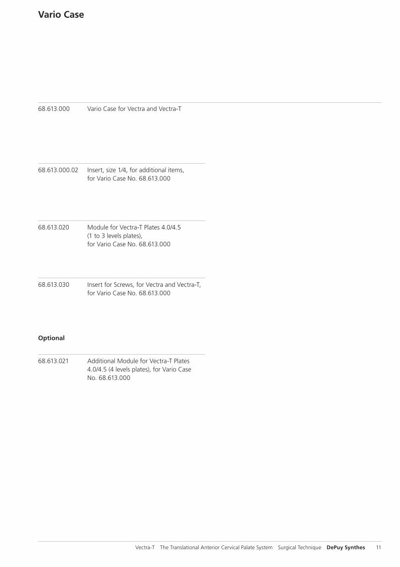
68.613.000 Vario Case for Vectra and Vectra-T
68.613.000.02 Insert, size 1⁄4, for additional items, for Vario Case No. 68.613.000
68.613.020 Module for Vectra-T Plates 4.0/4.5 (1 to 3 levels plates), for Vario Case No. 68.613.000
68.613.030 Insert for Screws, for Vectra and Vectra-T, for Vario Case No. 68.613.000
Optional
68.613.021 Additional Module for Vectra-T Plates 4.0/4.5 (4 levels plates), for Vario Case No. 68.613.000

12 DePuy Synthes Vectra-T The Translational Anterior Cervical Palate System Surgical Technique
Instruments
Plate manipulation instruments
324.101 Fixation Pin for temporary use Holds the plate securely to the bone prior to final placement of screws.
324.101S Fixation Pin for temporary use, sterile
03.600.004 Bending Pliers for Vectra Plates For contouring Vectra-T plates to the desired curvature.
352.312 Holding Sleeve for temporary Fixation Pin For use with Screwdriver 324.105.

Vectra-T The Translational Anterior Cervical Palate System Surgical Technique DePuy Synthes 13
Screw site preparation instruments
324.107 Handle with Quick Coupling For use with drill bits and taps.
311.402 Tap for Cancellous Bone Screws B 4.0 mm, length 220 mm, in combination with 324.107
324.111 Awl B 2.5 mm with trocar tip Breaks the cortex.
311.404 Tap for Cancellous Bone Screws B 4.5 mm, length 220 mm, in combination with 324.107
324.151–159 Drill Bit B 2.5 mm, lengths 12–20 mm, 2-flute, for Quick Coupling, in combination with 324.107
03.613.222–226 Drill Bit B 2.5mm, lengths 22–26mm, 2-flute, for Quick Coupling, in combination with 324.107
387.292 Screw length indicator, depth up to 50 mm For determining the correct screw length

14 DePuy Synthes Vectra-T The Translational Anterior Cervical Palate System Surgical Technique
Instruments
03.600.002 Drill Guide 8.0/3.2, with fixed angle, for Vectra and Vectra-T Functions as a plate holder and works as a guide for drill bits when preparing inser-tion of fixed angle screws.
03.600.003 Drill Guide 8.0/3.2, with variable angle, for Vectra and Vectra-T Functions as a plate holder and works as a guide for drill bits when preparing insertion of variable angle screws.
03.613.001 Drill and Screw Guide, for Vectra and Vectra-T Facilitates use of awl, drill bits and taps and allows for fixed and variable angle screw insertion.

Vectra-T The Translational Anterior Cervical Palate System Surgical Technique DePuy Synthes 15
324.105 Screwdriver for Insertion, self-holding For inserting screws and temporary fixation pins.
Screw insertion instrument
352.311 Screwdriver for Extraction For extracting screws from the plate.
324.071 Cleaning Instrument for Screw Head For removal of tissue in the screw head
prior to attaching the Screwdriver for Extraction.
Extraction and revision instruments
16 DePuy Synthes Vectra-T The Translational Anterior Cervical Palate System Surgical Technique
Implant Selection and Preparation
1Select and insert graft
Following approach and decompression, insert the appropri-ately sized graft.
Vectra-T The Translational Anterior Cervical Palate System Surgical Technique DePuy Synthes 17
2Select and bend plate
Required Instrument
03.600.004 Bending Pliers for Vectra Plates
Optional Instruments
03.600.002 Drill Guide 8.0/3.2, with fixed angle, for Vectra and Vectra-T
03.600.003 Drill Guide 8.0/3.2, with variable angle, for Vectra and Vectra-T
Select a plate with appropriate hole spacing. Plate may be brought in position with the Drill Guide (fixed angle or vari-able angle).
Precaution: It must be considered that the intervertebral discs in the neck region are slightly inclined from anterocau-dal to posterocranial. Screws should remain in the vertebral body and not penetrate the intervertebral discs. Make sure there will be enough space between the intact adjacent intervertebral discs and the screws.
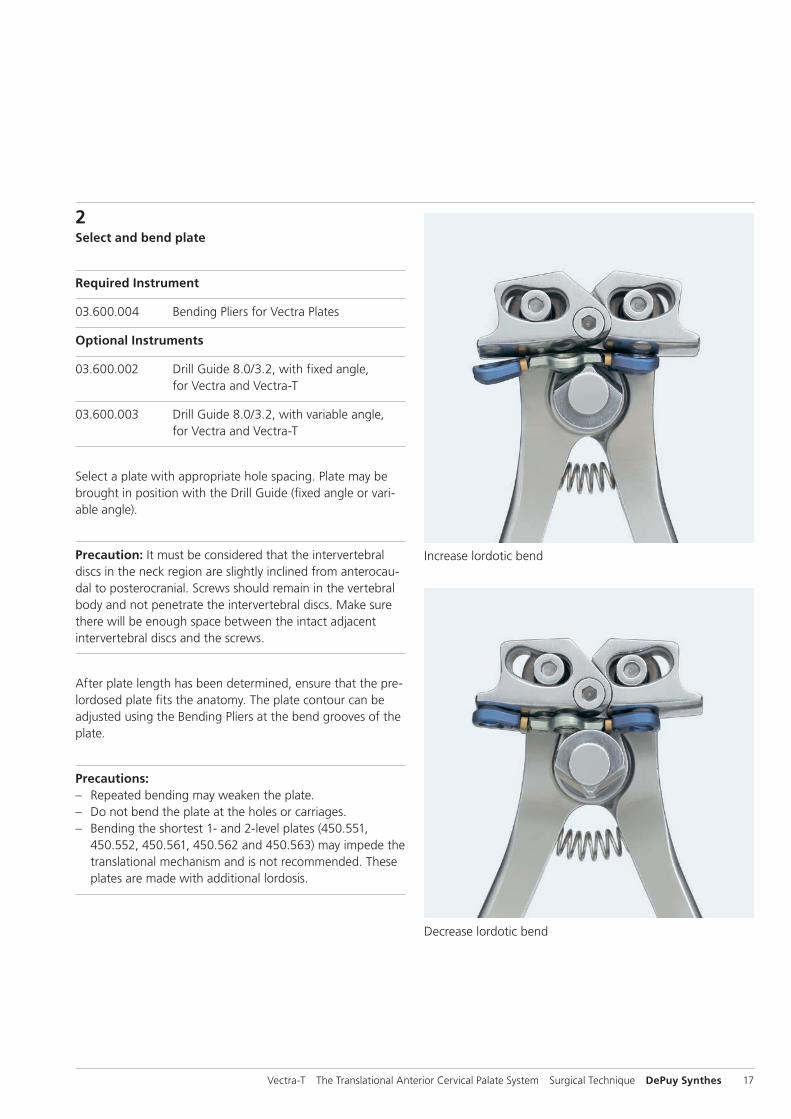
After plate length has been determined, ensure that the pre-lordosed plate fits the anatomy. The plate contour can be adjusted using the Bending Pliers at the bend grooves of the plate.
Precautions: – Repeated bending may weaken the plate. – Do not bend the plate at the holes or carriages. – Bending the shortest 1- and 2-level plates (450.551,
450.552, 450.561, 450.562 and 450.563) may impede the translational mechanism and is not recommended. These plates are made with additional lordosis.
Decrease lordotic bend
Increase lordotic bend
18 DePuy Synthes Vectra-T The Translational Anterior Cervical Palate System Surgical Technique
3Secure plate with Fixation Pins
Required Instruments
324.101(S) Fixation Pin for temporary use, (sterile)
324.105 Screwdriver for Insertion, self-holding
Optional Instrument
352.312 Holding Sleeve
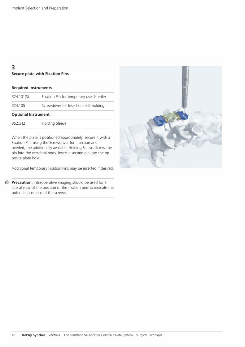
When the plate is positioned appropriately, secure it with a Fixation Pin, using the Screwdriver for Insertion and, if needed, the additionally available Holding Sleeve. Screw the pin into the vertebral body. Insert a second pin into the op-posite plate hole.
Additional temporary Fixation Pins may be inserted if desired.
Precaution: Intraoperative imaging should be used for a lateral view of the position of the fixation pins to indicate the potential positions of the screws.
Implant Selection and Preparation

Vectra-T The Translational Anterior Cervical Palate System Surgical Technique DePuy Synthes 19
Option A: Awl and Self-Drilling Variable Angle Screws
A1Break cortexRequired Instrument
324.111 Awl B 2.5 mm with trocar tip
Insert the awl by rocking it into the screw hole. Push down at the desired screw angle, while twisting the awl handle. Remove the awl while maintaining hole and plate alignment. To remove the awl, pull straight up to disengage it from the clip. Do not angle or lever the awl to either side.
Precaution: Intraoperative imaging should be used to verify awl position.
4.0 mm 4.5 mm

20 DePuy Synthes Vectra-T The Translational Anterior Cervical Palate System Surgical Technique
A2Insert variable angle screw
Required Instrument
324.105 Screwdriver for Insertion, self-holding
Load the appropriate length variable angle self-drilling screw onto the Screwdriver. Advance the screw until the head of the screw is fully seated in the plate and the plate is lagged to the bone.
Warning: For long spans or poor bone quality: The surgeon is urged to consider the nature of such cases. The treatment may require the use of screws longer than 16 mm, and/or posterior fixation for this kind of inherently unstable cases.
Precautions: – Only variable angle screws are recommended in the elon-
gated holes of 3- and 4-level plates. The screw head ge-ometry of fixed angle screws may impede translation.
– It must be considered that the intervertebral discs in the neck region are slightly inclined from anterocaudal to pos-terocranial. Screws should remain in the vertebral body and not penetrate the intervertebral discs. Make sure there will be enough space between the intact adjacent intervertebral discs and the screws.
– The 4.5 mm screw may be used as an emergency screw where the 4.0 mm screw has stripped the bone and a larger screw thread is required.
– Intraoperative imaging should be used to verify screw position.
– Any screw may be placed in the round screw holes. – The total amount of translation can be customized
(e.g., for a corpectomy) by removing carriage spacers and moving the carriages within the allowable range before screw placement.
– The carriage on the cranial end (for 3- and 4- level plates only) can translate 3 mm while all other carriages can translate 2 mm.
– Intermediate elongated holes allow screws to translate up to 2 mm.
Option A: Awl and Self-Drilling Variable Angle Screws
Vectra-T The Translational Anterior Cervical Palate System Surgical Technique DePuy Synthes 21
A3Remove carriage spacers
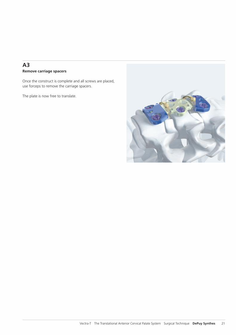
Once the construct is complete and all screws are placed, use forceps to remove the carriage spacers.
The plate is now free to translate.
22 DePuy Synthes Vectra-T The Translational Anterior Cervical Palate System Surgical Technique
Option B: Drill Sleeves and Self-Tapping Screws
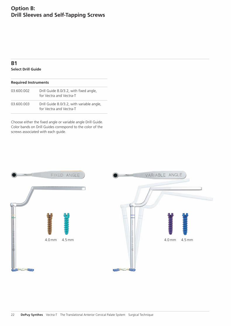
B1Select Drill Guide
Required Instruments
03.600.002 Drill Guide 8.0/3.2, with fixed angle, for Vectra and Vectra-T
03.600.003 Drill Guide 8.0/3.2, with variable angle, for Vectra and Vectra-T
Choose either the fixed angle or variable angle Drill Guide. Color bands on Drill Guides correspond to the color of the screws associated with each guide.
4.0 mm 4.5 mm 4.0 mm 4.5 mm

Vectra-T The Translational Anterior Cervical Palate System Surgical Technique DePuy Synthes 23
B2Drill pilot hole
Required Instruments
324.151–159 Drill Bits B 2.5 mm, lengths 12–20 mm, for Quick Coupling
03.613.222–226 Drill Bits B 2.5 mm, lengths 22–26 mm, for Quick Coupling
324.107 Handle with Quick Coupling
Optional Instrument
387.292 Screw length indicator, depth up to 50 mm
Insert the Drill Guide by rocking it into the screw hole. Use the appropriate length drill bit and handle to drill the pilot hole for the screw. The depth stop will contact the Drill Guide to limit drilling depth.
Precaution: Intraoperative imaging should be used to check the drilling operation.
B3Remove Drill Guide
Remove the Drill Guide by pulling straight up to disengage it from the clip. Do not angle or lever the sleeve to either side.

24 DePuy Synthes Vectra-T The Translational Anterior Cervical Palate System Surgical Technique
Option B: Drill Sleeves and Self-Tapping Screws
B4Insert screw
Required Instrument
324.105 Screwdriver for Insertion, self-holding
Optional Instruments
311.402 Tap for Cancellous Bone Screws B 4.0 mm
311.404 Tap for Cancellous Bone Screws B 4.5 mm
324.107 Handle with Quick Coupling
Load the appropriate length variable angle or fixed angle self-tapping screw onto the screwdriver. Advance the screw until the head of the screw is fully seated in the plate and the plate is lagged to the bone.
Warning: For long spans or poor bone quality: The surgeon is urged to consider the nature of such cases. The treatment may require the use of screws longer than 16 mm, and/or posterior fixation for this kind of inherently unstable cases.
Precautions: – Only variable angle screws are recommended in the elon-
gated holes of 3- and 4-level plates. The screw head ge-ometry of fixed angle screws may impede translation.
– It must be considered that the intervertebral discs in the neck region are slightly inclined from anterocaudal to pos-terocranial. Screws should remain in the vertebral body and not penetrate the intervertebral discs. Make sure there will be enough space between the intact adjacent intervertebral discs and the screws.
– The 4.5 mm screw may be used as an emergency screw where the 4.0 mm screw has stripped the bone and a larger screw thread is required.
– Intraoperative imaging should be used to verify screw position.

Vectra-T The Translational Anterior Cervical Palate System Surgical Technique DePuy Synthes 25
B5Remove carriage spacers
Once the construct is complete and all screws are placed, use forceps to remove the carriage spacers.
The plate is now free to translate.

26 DePuy Synthes Vectra-T The Translational Anterior Cervical Palate System Surgical Technique
Option C: Drill and Screw Guide
C1Insert Drill and Screw Guide
Required Instrument
03.613.001 Drill and Screw Guide, for Vectra and Vectra-T
Use the Drill and Screw Guide in the small post holes.
Vectra-T The Translational Anterior Cervical Palate System Surgical Technique DePuy Synthes 27
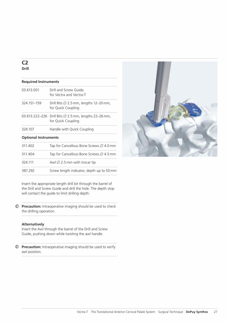
C2Drill
Required Instruments
03.613.001 Drill and Screw Guide, for Vectra and Vectra-T
324.151–159 Drill Bits B 2.5 mm, lengths 12–20 mm, for Quick Coupling
03.613.222–226 Drill Bits B 2.5 mm, lengths 22–26 mm, for Quick Coupling
324.107 Handle with Quick Coupling
Optional Instruments
311.402 Tap for Cancellous Bone Screws B 4.0 mm
311.404 Tap for Cancellous Bone Screws B 4.5 mm
324.111 Awl B 2.5 mm with trocar tip
387.292 Screw length indicator, depth up to 50 mm
Insert the appropriate length drill bit through the barrel of the Drill and Screw Guide and drill the hole. The depth stop will contact the guide to limit drilling depth.
Precaution: Intraoperative imaging should be used to check the drilling operation.
AlternativelyInsert the Awl through the barrel of the Drill and Screw Guide, pushing down while twisting the awl handle.
Precaution: Intraoperative imaging should be used to verify awl position.

28 DePuy Synthes Vectra-T The Translational Anterior Cervical Palate System Surgical Technique
C3Insert screw
Required Instruments
03.613.001 Drill and Screw Guide, for Vectra and Vectra-T
324.105 Screwdriver for Insertion, self-retaining
Insert the appropriate length screw through the barrel of the Drill and Screw Guide and advance it until the screw head almost engages the plate (as indicated by the groove on the screwdriver shaft lining up with the top of the Drill and Screw Guide). Retract the Drill and Screw Guide by pulling it along the screwdriver shaft, just before the screw seats in the plate hole, to visually confirm that the screw is seating. Advance the screw until it lags the plate to the bone.
Warning: For long spans or poor bone quality: The surgeon is urged to consider the nature of such cases. The treatment may require the use of screws longer than 16 mm, and/or posterior fixation for this kind of inherently unstable cases.
Precautions: – Only variable angle screws are recommended in the elon-
gated holes of 3- and 4-level plates. The screw head ge-ometry of fixed angle screws may impede translation.
– It must be considered that the intervertebral discs in the neck region are slightly inclined from anterocaudal to pos-terocranial. Screws should remain in the vertebral body and not penetrate the intervertebral discs. Make sure there will be enough space between the intact adjacent intervertebral discs and the screws.
– The 4.5 mm screw may be used as an emergency screw where the 4.0 mm screw has stripped the bone and a larger screw thread is required.
– Intraoperative imaging should be used to verify screw position.
Option C: Drill and Screw Guide

Vectra-T The Translational Anterior Cervical Palate System Surgical Technique DePuy Synthes 29
C4Remove carriage spacers
Once the construct is complete and all screws are placed, use forceps to remove the carriage spacers.
The plate is now free to translate.

30 DePuy Synthes Vectra-T The Translational Anterior Cervical Palate System Surgical Technique
Implant Removal
1Clean screw head
Required Instrument
324.071 Cleaning Instrument for Screw Head
If access to the screw head is blocked by tissue, use the Cleaning Instrument for Screw Head to clean out material. Insert the instrument into the screw head and twist the handle back and forth until material is removed.

Vectra-T The Translational Anterior Cervical Palate System Surgical Technique DePuy Synthes 31
Insert the driver shaft into the screw head recess.
Tighten the knob on the handle to thread the inner shaft into the mating thread of the screw.
Advance the sleeve downward. Turn the handle counterclockwise while holding on to the sleeve to extract the screw.
3Remove plate
After all the screws have been romoved, the plate can then be removed.
2Remove screw
Required Instrument
352.311 Screwdriver for Extraction
For screw removal the Screwdriver for Extraction must be used. Insert the driver shaft into the screw head recess. Tighten the knob on the handle to thread the threaded tip of the inner shaft into the mating thread of the screw. Advance the sleeve downward to contact the upper surface of the plate by turning the sleeve clockwise.
Do not rotate the sleeve after it has contacted the sur-face of the plate. While holding the sleeve, turn the handle counterclockwise to extract the screw.
Precaution: After the second screw insertion trial, the plate needs to be replaced.
Precaution: If the inner shaft knob is not fully tightened to the handle, breakage of the driver may occur and could po-tentially harm the patient.
Warning: The extraction screw driver should only be used for screw removal; use of the extraction screwdriver for screw insertion may lead to driver and/or implant breakage.


Synthes GmbHEimattstrasse 34436 OberdorfSwitzerlandTel: +41 61 965 61 11Fax: +41 61 965 66 00www.depuysynthes.com 0123 ©
DeP
uy S
ynth
es S
pine
, a d
ivis
ion
of S
ynth
es G
mbH
. 201
6.
All
right
s re
serv
ed.
036.
00
0.4
48
DSE
M/S
PN/0
316/
04
68
07/1
6
Not all products are currently available in all markets.
This publication is not intended for distribution in the USA.
All surgical techniques are available as PDF files at www.depuysynthes.com/ifu