vb-g 영문 07.07.19~현재 -유효
TRANSCRIPT

Page 1
OPERATING MANUAL
[VISCO BATH] Model: VB-25G, 40G
Manual No: 00HAA0001184 (Version : 5.0)
This operating manual describes the important subjects to maintain the product¡s functions and to use
it safely. Especially, be sure to read <Safety Precaution> carefully before you use this equipment.
Please keep this operating manual close to the equipment to use it after reading through it once.
Please place it where the new user can find it easily for the safety use when you hand over or lend
the equipment to others

Page 2
Table of Contents Chapter 1 : Introduction
Caution about the operating manual ---------------------------------- 4 Warning mark ------------------------------------------------------------- 4 Caution for safe operation and unauthorized modification ---------5 Disclaimer ----------------------------------------------------------------- 5
Chapter 2 : Check the condition of unit -----------------------6,7
Chapter 3 : Installation
Contents------------------------------------------------------------------- 9 Installation ----------------------------------------------------------------10
Chapter 4 : Safety Alert and Caution Safety Alert -------------------------------------------------------------- 12 Safety Caution ----------------------------------------------------------- 13
Chapter 5 : Names of each Component & Functions Part names and functions
Main Body ---------------------------------------------------------- 15 Over temp limit ---------------------------------------------------- 16
Chapter 6 : Controls and functional element Operating and functional element------------------------------------ 18 Temperature setting procedure----------------------------------------20
Chapter 7 : Maintenance and Troubleshooting
Maintenance ------------------------------------------------------------ 25 Safekeeping and Cleaning -------------------------------------------- 26 Troubleshooting--------------------------------------------------------- 27
Chapter 8: Specifications and Circuit diagram Specifications ----------------------------------------------------------- 31 Circuit diagram --------------------------------------------------------- 32
Chapter 9: Warranty and Service Warranty service ------------------------------------------------------- 34 Exceptions from warranty ---------------------------------------------34 Service request ---------------------------------------------------------34 Return process --------------------------------------------------------- 34
Chapter 10: Installation and Operation of Communication program Installation of monitoring program ----------------------------------36 Operation of monitoring program ----------------------------------- 37

Page 3
Chapter 1
Introduction
Thank you for purchasing the Lab Companion Visible Bath. Lab Companion Visible bath performs exact constant temperature and bath circumstance related to the operator¡s experimental condition. Excellent Temperature uniformity with circulating running water by circulation pump. Visible bath provides the great inner view by inner glass window installed back and forth also Glass viscometer. Designed double structure to prevent from vibration and tremble by running water. Before using the Bath, please comprehend the manual in detail.
Including;
Caution about the operating manual
Warning mark
Caution for safe operation and unauthorized modification
Disclaimer

Page 4
Caution about the operating manual 1. Always keep this instruction near to the instrument.
2. Copying and distributing part or the whole of this the operating instruction with no permission
are prohibited with the law.
3. The operating instruction promised perfection but please ask an agent or us if you have any question about insufficient points, error and omission on the operating instruction.
Warning mark 1. This operating instruction uses the warning Signal Word for safe operation to prevent the
users from accidents or damage beforehand. 2. Defined by the Symbol Mark about the safety caution.
¡Warning¡ means that the user may have serious damage and even die by improper handling on this unit.
¡Caution¡ means that the user may have minor damage and unit may have physical damage by improper handling on this unit.
Protective Ground Terminal It marks the terminal must be connected Ground prior to operating the product.
It marks additional information on the operation and features of the product.
3. Be fully aware of the warning contents during operation. 4. Please exchange original label to the new warning label when it is unreadable from warning
out. ☞ Please request the new label to an agent or us.

Page 5
Caution for safe operation and unauthorized modification
1. In order to protect the product and system, please use the product in accordance with the instructions.
2. We shall not be responsible for any incidental or abnormal operation for breach of any
express or implied warranty on this product or any part thereof. 3. It forbids reorganization of Inside of the product or adds.
4. Please contact the agent or us in case of the component and the consumable parts of the
product will be replaced.
5. Do not give a strong shock to the product. It becomes the cause of product damage and wrong operations.
Disclaimer
1. In no event will Jeio Tech industries be liable for any incidental or consequential damages for breach of any implied warranty relating to the product.
2. Any special indirect or consequential property or commercial damage of any nature
whatsoever. Some cases do not allow the exclusion of incidental or consequential damages, so the above limitation may apply to you.

Page 6
Chapter 2
Check the condition of unit
Before you install Visible Bath, inspect it for damage that may have occurred in transportation. Confirm any damage for compensating following the Compensation regulations and transportation of Lab Companion.

Page 7
Check the condition of unit before unpack Protection from any damage occurring in transit, Lab Companion administers excellent packing and radical transportation. Any damage or loss during transit, all responsibility is filled with the delivery carrier. After receiving the unit, carefully unpack and inspect it for damage. If the unit is damaged or loss during transit, Make sure as follows to be protected from the ¡Lab Companion Regulations¡
.
Confirmation a damaged unit 1. Check the front and rear sides of the unit under packed condition.
2. Carefully unpack the package.
3. Check with care any damage during the transportation of the unit
4. Check the parts (i.e. accessories- Page 9) of the unit.
Compensation regulation of damaged unit If the unit is damaged, contact the delivery service company immediately.
1. Keep the condition as it delivered and wait for the confirmation by the carrier.
2. Within 15 days, submit an application be made in writing to the delivery service company.
Do not discard the carton or packing material for the unit until you have checked all of the damaged parts.
Compensation regulation of transport 1. Any damage that is occurred during the transport is responsible to the delivery service
company. 2. Except for all damage from the transport, we Jeio Tech will service or return.
3. If Jeio Tech or our authorized dealers do not deliver the unit, Jeio Tech disclaims all the
responsibility for the damage.
Page 8
Chapter 3
Installation
Before installation, be sure to check the electric conditions for electric safe. All persons expected to carry out operation, installation and maintenance of the unit, read and understand the safety information and operating instructions. Including;
contents
Installation
Check points Select a proper place Level off Power connection

Page 9
Contents
After unpacking, please check listed Bath component description as follows. If you didn¡t receive one or more component as follow, Contact the Jeio Tech Service center or the distributor where you purchased.
Operating manual After unpacking, check the operating manual. If you didn¡t receive the operating manual, Contact the distributor or the Jeio Tech service center.
Fuse During being in use, if you contact the service center or the distributor, you will receive the service.
Software CD for communication This software is for installation of Lab Tracer.
Cable for communication This is a cable for RS-232 communication.

Page 10
Installation
The machine should be installed on a safe and proper environment following to the below Check Points
- Select a proper place, Level off the machine, - Power connection
Select a proper place
1. Operating condition Room condition of temperature and humidity should be normal as 18 ℃ ~ 25℃, below 80%RH.
2. Environmental condition Do not expose the machine to direct ray of light.
3. Setting place The floor should be on flat and leveled ground.
4. Space The machine should be kept at least 1.5m from any illuminators and 20 cm from walls.
The machine should be operated at the optimum condition for cleanness, electricity and preparation against fire.
Level off All of the bottom sides should be leveled.
Power connection Check the ID Plate on the back side of the machine to find the electric conditions. Power must be used upper 2 classes grounded.
Do not connect the power before checking
how to do correct operation.
1. Check if the plug condition and electric wires are normal. 2. Check the connection of ground wire.
Check the power plug to find if the electric conditions are correct. The voltage fluctuation should be within 10%.

Page 11
Chapter 4
Safety Alert and Caution
¡ Alert¡ shows that users can be dead or seriously wounded by wrong operation.
¡ Notice¡ shows that users can be wounded or machines broken by wrong operation.
¡Signal Word¡ is used in the operation manual for safe and proper operation and keeps users from being damaged by accidents. Each ¡Symbol Mark¡ is identified following to the degree of importance and danger. Pay attention to the ¡Alert¡ and ¡Notice¡ in the manual to avoid from any accidents.

Page 12
Safety Alert
¡Alert¡ shows that users can be dead or seriously wounded by wrong operation.
Check the voltage, phase and capacity on the ID plate before installation. Sources of electricity should be separately wired.
The sources of electricity should be grounded.
The sources of electricity without ground connection can cause serious damage to users or the machine. Don¡t earth the machine to gas pipes or water pipes.
Do not connect multiple power cord. It can cause fire and malfunction.
Running water recommended must be non-flammability. In case of flammability, the flashing point of running water must be over 40℃.
Running water can be circulated and pumped below
20degrees. Running water circulated and pumped can be used
below ambient 20℃. Running water must be lower 5℃ from the flashing point. (Fp-5)
Don¡t install the machine near to places where
inflammable gas can be leaked. Do not use the machine near to places where explosion can be happened due to organic evaporating gases.
Explosive materials: Acid, Esther, Nitro compound Inflammable materials: salt peroxides, inorganic peroxide, salt acids
Do not put inflammables and explosives in the machine. Put off the power plug if some sounds and smell,
smokes are happened. Keep out the machine from heating source and sun
direct. Install the unit ambient 5 ~40 and below ℃ ℃80%RH.
Do not use the machine at places where moisture is high and flooding can be happened.
Do not disassemble or fix, change the machine. Do not move the machine when running water heated.
Must drain running water completely when moving the machine. Overflowing running water can cause malfunction and burn.
At least 2 persons should move the machine when it is necessary.
Be careful to enter moisture, organic solvents, and dust and corrosiveness gas.
Main Power
Safety

Page 13
Caution
¡Notice¡ shows that users can be wounded or machines broken by wrong operation.
Do not put heavy things on the power line. Do not put
the machine on the line. It causes fire and electric shock.
Connect the plug correctly and do not touch it with hands. It can cause fire if the connection is not fit. It can cause fire and damage to users.
Install the machine near to the power cord can be
easily reached. Do not install the machine near the high frequency
noise place. Keep out a high-frequency welder and mass capacity SCR Controller.
Do not put inflammables and explosives in the machine. Do not install the machine near to the organic solvents.
It may cause fire and malfunction. Do not make the machine wet while cleaning. Do not
put liquid on the machine. If the machine is wet, off the power and contact where you purchase the machine to check it.
Do not shock the machine or vibrate it. It can cause damage to the machine.
Do not clean the machine with solvent abstergent. Use smooth cloths.
Cleaning with solvent can cause fire and deformity.
Main Power
Safety

Page 14
Chapter 5
Names of each Component & Functions
Please, we recommend that operator learns name of each part of main body and function & and operation of display before using unit. If you do not understand any, please, contact with agent or Jeio tech. Including; Part names and functions
Main Body
Over temp. limit
Page 15
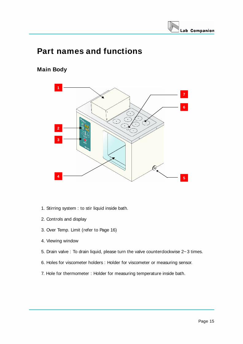
Part names and functions Main Body
1. Stirring system : to stir liquid inside bath. 2. Controls and display 3. Over Temp. Limit (refer to Page 16)
4. Viewing window 5. Drain valve : To drain liquid, please turn the valve counterclockwise 2~3 times. 6. Holes for viscometer holders : Holder for viscometer or measuring sensor. 7. Hole for thermometer : Holder for measuring temperature inside bath.
1
2
3
4 5
6
7

Page 16
Over Temp. Limit
Over Temp. Limit This safety device cuts mains of equipment and the unit stops when it detects high temperature over set temperature. Indication : Buzzer and O/T LED blinking. To start the unit again, press START/STOP key. Note) Please, eliminate the potential dangerous factor.
Knob

Page 17
Chapter 6
Controls and functional element Please, learn controls and functional element before operating unit. Including; Operating and Functional element
Temperature setting procedure
Additional functions of TEMP key Advanced 3 Temperature setting function BIAS function (Temperature calibration) Auto Tune function (Optimizing temp. control) Change temperature unit
Timer setting procedure
Additional functions of Timer key
Setting stirring speed Power failure compensation function
Lock function
Page 18
Operating and functional element
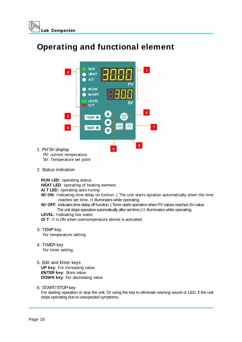
1. PV/SV display PV: current temperature
SV: Temperature set point 2. Status indication
RUN LED: operating status. HEAT LED: operating of heating element. A/T LED: operating auto-tuning W/ON: Indicating time delay on funtion. ( The unit starts opration automatically when the time
reaches set time. It illuminates while operating. W/OFF: Indicates time delay off function. ( Timer starts operation when PV values reaches SV value. The unit stops operation automatically after set time.) It illuminates while operating. LEVEL: Indicating low water. O/T: It is ON when overtemperature device is activated.
3. TEMP key For temperature setting.
4. TIMER key For timer setting.
5. Edit and Enter keys UP key: For increasing value. ENTER key: Store value DOWN key: For decreasing value
6. START/STOP key For starting operation or stop the unit. Or using the key to eliminate warning sound or LED, if the unit stops operating due to unexpected symptoms.
3
4
5
6
1
7
8
2

Page 19
7. A/T key Press and hold the key for 1 second to strat Auto Tune fucntion.
8. LOCK key
1. Lock keys.
2. Press an hold the key for 3 seconds to set or release LOCK function.

Page 20
Temperature setting procedure
1. Press TEMP key : Value on SV indicator blinks.
2. Adjust value by using UP and DOWN key. : set temperature
3. Press ENTER key to store temperature.
Press START/STOP key to start running.
Additional functions of TEMP key
1) Advanced Temperature setting function : Store 3 different temperatre in advance and recall each temperature.
A) How to store 3 different temperature in advance ① Press TEMP key 2 times continuously. ② SV1 shows on PV indicator, value can be put on SV indicator.
③ Adjust value by using UP and DOWN key and press ENTER key to finish temperature
setting ④ The value is saved in SV1 and current set value is changed. ⑤ If press TEMP key one more time, SV2 shows on PV indicator and a different value can
be saved by using UP and DOWN key. ⑥ If press TEMP key one more time, SV3 shows on PV indicator and value can be saved.
Temperature display resolution : 0.01 resolution from at 0 ℃ to 99.99℃
: 0.1 resolution from 100.0℃ to 150.0℃

Page 21
B) How to recall and select among stored 3 different temperature
① Press TEMP key 2 times. ② Verify stored temperature on SV1. : SV1 on PV indicater and Stored temperature on SV
indicator ③ Press ENTER key ④ Press START/STOP key to operature SV1 temperature. ⑤ To operate SV2, press TEMP key 3 times. ⑥ To operate SV3, press TEMP key 4 times.
2) BIAS function (Temperature calibraton)
: Compensates temperature difference between reference sensor and equipped sensor in unit.
BIAS setting procedure ① Press TEMP key 6 times. ② Press UP or DOWN key 1 time.
③ Current temperature shows on SV indicator. ④ Input the difference between your reference sensor and actual temperature inside chamber by using UP and DOWN key. ⑤ Press ENTER key to store the value. ⑥ Press START/STOP key to operate the unit.
3) Auto Tune function (Optimizing temp. control)
: optimizes temperature linearity by tuning PID parameter. When Auto tune function needs; Temperature fluctuation. / It takes too long to reach set point.
① Set temperaure. ② Press and hold A/T key for 3 second. - A/T LED is ON. ③ Press START/STOP key. - A/T LED blinks. ④ The unit controls temperature after A/T is finished.
.
Recommend please, perform Auto Tuning at the first use of the unit. Also after long period of time, unit needs Auto Tune.
Page 22
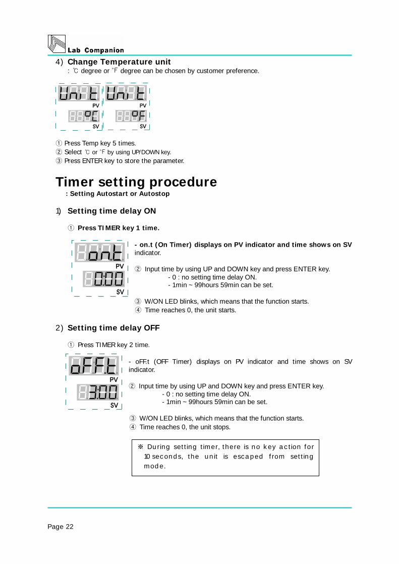
4) Change Temperature unit : ℃ degree or ℉ degree can be chosen by customer preference.
① Press Temp key 5 times. ② Select or by using UP/DOWN℃ ℉ key. ③ Press ENTER key to store the parameter.
Timer setting procedure : Setting Autostart or Autostop 1) Setting time delay ON
① Press TIMER key 1 time. - on.t (On Timer) displays on PV indicator and time shows on SV
indicator. ② Input time by using UP and DOWN key and press ENTER key.
- 0 : no setting time delay ON. - 1min ~ 99hours 59min can be set.
③ W/ON LED blinks, which means that the function starts. ④ Time reaches 0, the unit starts.
2) Setting time delay OFF ① Press TIMER key 2 time.
- oFF.t (OFF Timer) displays on PV indicator and time shows on SV
indicator. ② Input time by using UP and DOWN key and press ENTER key.
- 0 : no setting time delay ON. - 1min ~ 99hours 59min can be set.
③ W/ON LED blinks, which means that the function starts. ④ Time reaches 0, the unit stops.
※ During setting timer, there is no key action for
10seconds, the unit is escaped from setting
mode.

Page 23
Additional functions of Timer key 1) Setting Stirring speed
: For good temperature uniformity ① Press TIMER key 4 times. - Value on SV indicator blinks. ② Adjust the stirring speed from 1 to 5 by using UP/DOWN key. ③ Press ENTER key to store the value. ④ Press START/STOP key to operate the unit.
2) Power failure compensation function : When power failure happens, user can select that unit keeps going or forces to stop.
① Press TIMER key 3 times. ② Select Yes or No by adjusting UP/DOWN key. ③ Press ENTER key to store the value. ④ Press START/STOP key to operate the unit.
LOCK function
: All keys do not work. ① Press and hold LOCK key for 3seconds.
- All keys lock. ② Press and hold LOCK key for 3 seconds again. - Lock function is released.
※ Caution
If set temperature is around room temperature Please set stirring speed under 3 level, otherwise temperature uniformity would be affected from heat generated by motor.

Page 24
Chapter 7
Maintenance & Troubleshooting This chapter shows symptoms while operation. Please contact us referring to the contents when the equipment has problems. Please keep in mind how to clean the equipment and maintain it regularly. Including; Maintenance
Every week/month/quarter/year. Keeping and cleaning of the equipment.
Keeping/External cleaning/Internal cleaning Troubleshooting
Power Temperature
Page 25
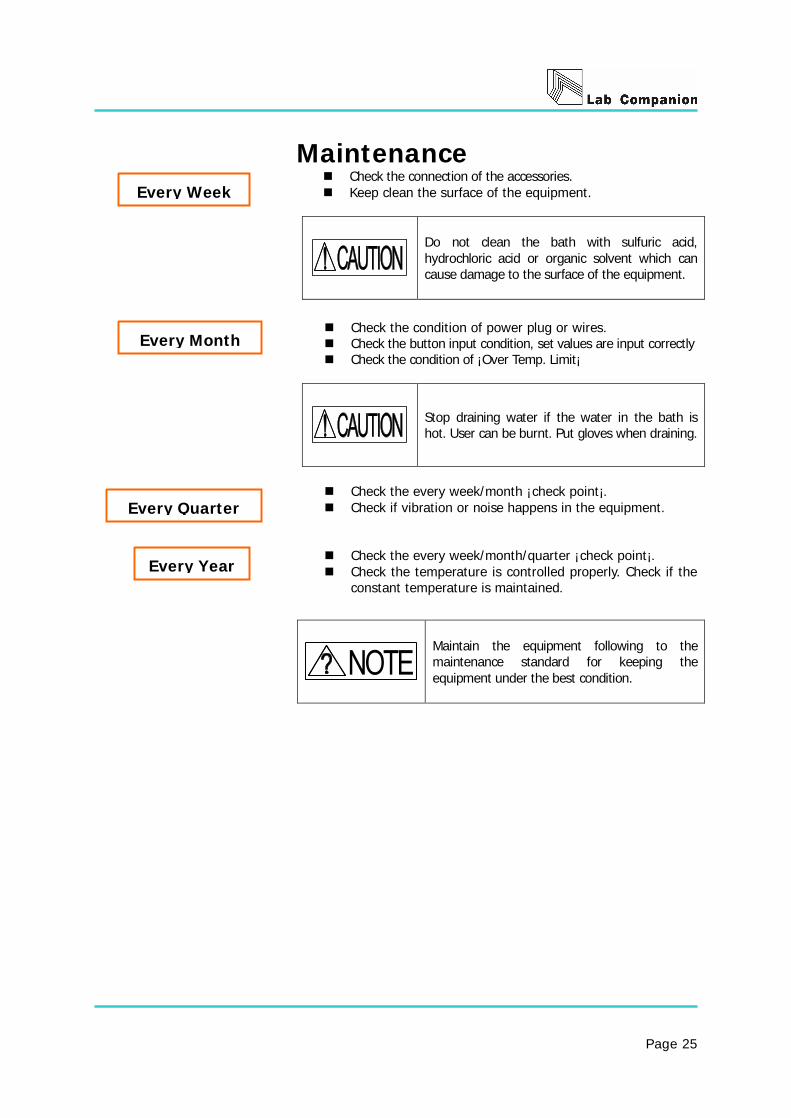
Maintenance Check the connection of the accessories. Keep clean the surface of the equipment.
Do not clean the bath with sulfuric acid, hydrochloric acid or organic solvent which can cause damage to the surface of the equipment.
Check the condition of power plug or wires. Check the button input condition, set values are input correctly Check the condition of ¡Over Temp. Limit¡
Stop draining water if the water in the bath is hot. User can be burnt. Put gloves when draining.
Check the every week/month ¡check point¡. Check if vibration or noise happens in the equipment.
Check the every week/month/quarter ¡check point¡. Check the temperature is controlled properly. Check if the
constant temperature is maintained.
Maintain the equipment following to the maintenance standard for keeping the equipment under the best condition.
Every Week
Every Month
Every Quarter
Every Year

Page 26
Safekeeping and Cleaning
Storage Keep the equipment following to the orders below in case no operation for a long time. 1. Power off. 2. Get rid of all solvents in the chamber. 3. Keep the equipment after packing for dust protection.
Cleaning External cleaning 1. Clean the external body by detergent. 2. Clean the external body by soft towel with pure water. 3. Clean the display with dry towel. Inner cleaning 1. Power off. 2. Clean in the bath by soft towel with detergent. 3. Clean it with dry towel.
Cleaning accessories 1. Soak accessories in detergent. 2. Clean it with pure water. 3. Keep it after drying.
Please contact local dealer in case cleaning the equipment without methods mentioned in the manual not to damage it while cleaning.
When getting rid of toxic chemical materials or gases licked out from the equipment, close safety gloves and mask for protection.
Cleaning Accessories
Inner cleaning
External cleaning
Storage

Page 27
Troubleshooting Follow the below when problems happen. Please ask service if problems not included in the table happen or can¡t be solved by the mentioned solutions. Power Symptoms Causes Solutions The equipment is not on.
Wrong electric standard. - Or -
Circuit breaker is off or power failure
- Or - The plug is not fit into the
socket properly. - Or -
Fuses are disconnected. - Or -
Socket/plug/power lines are damaged.
1. Check the ID plate on the back to find electric condition whether it¡s fit to the socket power.
If not sloved¡ . 2. Check if the power is off. If the circuit
breaker is off, fix it and operate the equipment again. If not solved¡
3. Plug the power to the socket again. If not solved¡
4. Check if the fuse set on the back of the equipment is short circuitted. Replace with a new one when short circuitted. If not solved¡
5. Check the socket/plug/power lines and replce with new one if they are damaged.
6. Contact your local dealer to fix the equipment if the problems are not yest solved.
Fuses are short circuitted friquently.
Electric standare of fuses are not fit.
- Or - Wires are damaged or shorted.
- Or - Power input parts are wet.
1. Connect the fuse tightly after checking voltage and amphere.
Refer to ¡Specifications¡ (Page 31) If not solved¡
2. Replace with a new wires if they are damaged or shorted.
If not solved¡ 3. If the power connecting parts are wet,
dry them and reconnect. 4. Contact your local dealer to fix the
equipment if the problems are not yet solved.
Machine doesn¡t work even though pressing Start/Stop button.
Faulty input of Controller SV 1. Press SET/ACT button to input RPM SV and press Start/Stop buttion to check the operation condition.
2. Contact your local dealer to fix the equipment if the problems are not yet solved
If circuit breakage is shorted continually.
Too many plugs are connected. 1. Check the voltage capacity supplied to the circuit breaker.
2. Check many similar equipments are connected on the socket. Use separate socket not exceeded of the voltage capacity.
3. Contact your local dealer to fix the equipment if the problems are not yet solved.

Page 28
Switch does not lit on even though putting it on.
Power failure. - Or -
The plug is not fit into the socket properly.
-Or- Fuses are disconnected.
- Or - Faulty power switch
connection. - Or -
Faulty power switch
1. Check the power failure 2. Plug the power to the socket again. If not solved¡ If not solved¡ 3. Replace with a new fuze if it¡s short
circuted. Refer the part name(page 15) 4. Contact your local dealer to fix the
equipment if the problems are not yet solved.
Display does not show anything when power is on.
Innter harness fails - Or -
Controller & Display fails.
1. Check the equipment by contacting the local dealer.
The equipment stops working automatically.
The equipment is affected by strong noise.
1. Check equipments with strong noises are installed near to the equipment and keep it far from them.
2. Contact your local dealer to fix the equipment if the problems are not yet solved.
Page 29
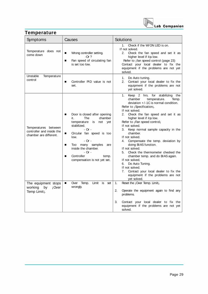
Temperature Symptoms Causes Solutions
Temperature does not come down
Wrong controller setting. -Or ?
Fan speed of circulating fan is set too low.
1. Check if the W/ON LED is on. If not solved.
2. Check the fan speed and set it as higher level if it¡s low.
Refer to ¡fan speed control (page 23) Contact your local dealer to fix the equipment if the problems are not yet solved.
Unstable Temperature control
Controller PID value is not set.
1. Do Auto tuning. 2. Contact your local dealer to fix the
equipment if the problems are not yet solved.
Temperatures between controller and inside the chamber are different.
Door is closed after opening it. The chamber temperature is not yet stabilized.
- Or - Circular fan speed is too
low. - Or -
Too many samples are inside the chamber.
- Or - Controller temp.
compensation is not yet set.
1. Keep 2 hrs. for stabilizing the chamber temperature. Temp. deviation +/-1C is normal condition.
Refer to ¡Specification¡. If not solved. 2. Check the fan speed and set it as
higher level if it¡s low. Refer to ¡Fan speed control¡ If not solved. 3. Keep normal sample capacity in the
chamber. If not solved. 4. Compensate the temp. deviation by
doing BIAS function. If not solved. 5. Check the thermometer checked the
chamber temp. and do BIAS again. If not solved. 6. Do Auto Tuning. If not solved. 7. Contact your local dealer to fix the
equipment if the problems are not yet solved.
The equipment stops working by ¡Over Temp Limit¡.
Over Temp. Limit is set wrongly.
1. Reset the ¡Over Temp. Limit¡. 2. Operate the equipment again to find any
problems. 3. Contact your local dealer to fix the
equipment if the problems are not yet solved.

Page 30
Chapter 8
Specifications and Circuit diagram
Check the specifications and circuit diagrams of the visible baths for
proper operation.
Including;
Specification
Circuit diagram

Page 31
Specification
MODEL VB-25G VB-40G Volume Capacity 25L 40L
Range Amb.~ 150℃(When cooler is equipped: from 10℃ )
Accuracy ¡ 0.02℃ at 50℃
Uniformity ¡ 0.02℃ at 50℃
Heat up time 50℃ within 30 min(230VAC/3000W)
Temp.
Controller PID Controlled microprocessor touch pad, Digital Display
Permissible environment condition
Temperature: 5℃ to 40℃ Relative humidity : 50% ~ 80%
Altitude : Up to 2,000m
Internal Stainless steel, 1.0t, Cubic Type
External Steel, 1.2t, Double painted and baked
Heater 3000W(1.5KW x2)/230V 3000W(1.5kWx2)/230V
Sensor Pt 100
Material
Insulation Poly-styrene 20mm
Bath 260*265*368 410*265*368
Top open 145*265 295*265 Size (mm) (WxDxH)
Overall 492*374*547 642*374*547
Holder Hole 5EA 8EA
Safety Device CLS(Custom Logical Safe)?Control System
Electric Requirement 230VAC, 13.2A 230VAC, 13.2A
Weight (Net) 28.0kg 37.0kg
※ The specs can be changed for improvement of capability and quality without
previous notice.

Page 32
Circuit diagram Models ?VB-25G, 40G

Page 33
Chapter 9
Warranty & Service
The equipment is covered by the warranty standard regulated by Jeio tech. Exceptions from the standards can¡t be covered by warranty. Including; Warranty and Service
Warranty and service Exceptions from warranty Service request Return process

Page 34
Warranty and Service
Warranty service If trouble occurs during product use, User can get free
service for one year from the date of purchase.
Exceptions from warranty
User can not be credited by warranty in case of as below.
① If trouble occurs by an act of God.
② If the equipment breaks down due to misusing of available
voltage.
③ If damage occurs by dropping a product, or impact.
④ If damage occurs in an appearance by organic solvents such as
thinner, benzene.
⑤ If damage occurs without following to notice in the
manual
⑥ If damage occurs by fixing the equipment by any person
who is not related with Jeio tech.
⑦ If damage occurs by a mistake of a customer
Service request 1. Contact the local agent with claim form including the below
conditions.
* Date of purchase * Name/Address/Contact no./E-mail * Serial Number * Symptoms
Return process Contact the local agent with claim form including the below conditions
* Date of purchase * Name/Address/Contact no./E-mail * Serial Number * Symptoms * Causes of returns * Forwarder information
Returns
Service
Exception
Under
Warranty

Page 35
Chapter 10
Installation and Operation of Communication program
VB can be remote controlled by installing controlling program in PC. Recorded data can be memorized and printed. Installation of monitoring program.
Operation of monitoring program.
Printing function.
Pattern Program.
Page 36
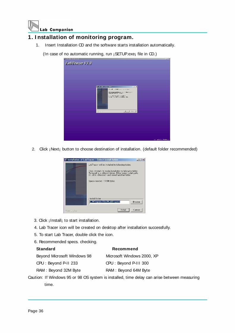
1. Installation of monitoring program. 1. Insert Installation CD and the software starts installation automatically.
(In case of no automatic running, run ¡SETUP.exe¡ file in CD.)
2. Click ¡Next¡ button to choose destination of installation. (default folder recommended)
3. Click ¡Install¡ to start installation.
4. Lab Tracer icon will be created on desktop after installation successfully.
5. To start Lab Tracer, double click the icon.
6. Recommended specs. checking.
Standard Recommend
Beyond Microsoft Windows 98 Microsoft Windows 2000, XP
CPU : Beyond P-II 233 CPU : Beyond P-III 300
RAM : Beyond 32M Byte RAM : Beyond 64M Byte
Caution: If Windows 95 or 98 OS system is installed, time delay can arise between measuring
time.

Page 37
2. Operation of monitoring program.
1) Connection for communication Click Comm Connect → and your PC and equipment start connection of communication.
(In case of no connection, click Comm Port → and try to other ports.
¡On Line¡ displays on the bottom of the software, once communication is connected
successfully. The window consists of 2 separate windows. Window on the top displays
Temperature set point and actual temperature and window on the bottom displays output
value of heating in graph mode.
Page 38
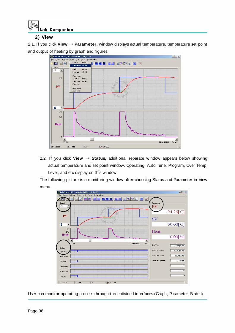
2) View 2.1. If you click View Parameter, → window displays actual temperature, temperature set point
and output of heating by graph and figures.
2.2. If you click View Status, → additional separate window appears below showing
actual temperature and set point window. Operating, Auto Tune, Program, Over Temp.,
Level, and etc display on this window.
The following picture is a monitoring window after choosing Status and Parameter in View
menu.
User can monitor operating process through three divided interfaces.(Graph, Parameter, Status)

Page 39
2.2.1. Graph displays;
Actual temperature (Red line) and set point (Blue line) on the top of separate
interfaces.
2.2.2. Status says that;
1. Operating represents the unit is Running.
- If blue line is Hi, the unit is On(operating). If blue line is Low, the unit is Off.
2. Auto Tune displays whether the unit performs Auto Tuning or not.
3. Program displays whether the unit is in programmable mode or not.
4. Over Temp. displays over heating condition of a unit.
2.2.3. Parameter interface has following values;
1. PV is actual temperature.
2. SV is temperature set point
3. Heat is output value of heating element.
4. Run Time says operating time after you press button.
5. Wait On Timer, Wait Off Timer displays remained time from setting time.
6. Power Frequency displays frequency of current power.

Page 40
3) Menu icon
○1 ○2 ○3 ○4 ○5 ○6 ○7 ○8 ○9 ○10 ○11 ○12 ○13
○1 File Open (Ctrl + O)
- To open saved graph.
○2 File Save (Ctrl + S)
- To save proceeding graph.
○3 Connect (Ctrl + C)
- To connect unit and PC via RS-232 communication.
○4 Disconnect (Ctrl + D)
- To disconnect RS-232 communication.
○5 Exit (Ctrl + X)
- To terminate Lab Tracer.
○6 Print (Ctrl + P)
- To print saver graph or proceeding graph. (refer to p30)
○7 Preview
- To preview before printing.
○8○9 Scroll icon
- To scroll graph.
○10○11 Auto Trace On/Off
- If you want to fix and monitor the last point of graph on the center of windows, Click Auto
Trace.
○12○13 Auto Span On/Off
- Set Y axis(temperature range) of graph manually or automatically. You can put values of
range if you choose manual.
○14 ○15 ○16 ○17 ○18 ○19 ○20 ○21 ○22 ○23 ○24 ○25
○14 To display Status interface. (Ctrl + T)
○15 To display Parameter interface. (Ctrl + R)
○16 Panel View
- When you click Panel View, the same appearance of display panel of unit pops up and you

Page 41
can control the unit by the pop-up window.
○17 Set Pattern of Program Run.
- Set Pattern of Program Run and makes unit in a programmable operation.
- Maximum number of pattern is 100 during 99hour.
○18 Program Run.
Program Run must be set in the main unit.
Program function can be controlled only by PC.
○19 ∼ ○22 Zoom In/Out
○23 ∼ ○24 To convert temperature scale from to or vice versa. (Note: Temperature scale of ℃ ℉
main body is not changed even though you convert temperature scale from Lab Tracer. To
changer temperature scale of main body, you must change setting value of controller in main
body.)
○25 To erase graph.
4) Print

Page 42
Print range①
- All : Print a total page.
- Print the screen : Print the current screen. (In case Graph, Status, Parameter
Frame on the window, they are printed. If not, they are not
printed.
- Current page : Print a page of the currently main screen.
- Selected pages : Print selected page(s).
Number of copies②
- Maximum number of copies are 100 by scrolling up and down button.
PV print interval③
- If you tick this option, PV and SV are printed in text mode.
④ Memo
- Can write brief memo on print. Maximum to 60characters.
Select Print⑤
- Can choose a printer.
♦ Preview and print
In case Print at equal intervals is ticked, PV and SV is printed in a regular interval
(see above) when you see preview and printing. If user wants to check a certain
point, move curser to the point and click. Green line with PV and SV will be printed
on the copies. (see above)

Page 43
Last Point Delete①
- Delete last set point.
All Point Delete②
- Delete all set points.
③ Zoon in / out
- Zoon in or Zoon out.
♦ Display
Performance of Display window is same as that of main display panel.
If communication via RS-232 between PC and main body is successful, user can
control main body with your PC at a distance.
4) Pattern Program

Page 44
The following window will be open in case click PRG icon or Pattern -> Pattern settings in
menu.
Pic 2. Pattern Program
In case you move mouse and click a certain point like pic 3., temperature set point and time,
step number display on left side of window.
Pic 3. SV Pattern after clicking a certain point of window.
I
If you want to edit the selected point, Drag & Drop the selected step (blue color).
It is very convenient to use short-keys when you want to change temperature and time.
Because temperature can be adjusted 1 degree unit and time adjusted one minute unit.
Short① -key
↑ : Increase temperature by 1 degree.
↓ : Decrease temperature by 1 degree.

Page 45
← : Decrease time by 1 minute.
→ : Increase time by 1 minute.
Alt + ↑ : Move an edit point to the right (the following step)
Alt + ↓ : Move an edit point to the left (a previous step)
Alt + ← : Move an edit point to the left (a previous step)
Alt + → : Move an editing point to the right (the following step)
Last step delete②
- Delete last set step.
All step delete③
- Delete all set steps.
Pattern save④
- Save programmed pattern.
- File extension is PIT.
- Choose a folder and write file name. Then, click save button.
Pattern open⑤
- Choose a pattern file and click open.
Start⑥
- Click the START icon to operate unit after Pattern is set.
Note: If the main body is under abnormal condition such as Door Open, Over Temp. and etc,
the main unit will not work.
Pic 4. Step information and control option.

Page 46
- If you put and set number of pattern repetition, the main body will work as programmed.
- If you tick ¡ Deleting the previous data¡ and press start icon, previous data will be
erased. Please, be cautious.
Caution※
- Maximum operating time is up 99 hours.
- If you program total working time over 99 hours, the unit does not perform in Program Mode.
Especially be cautious when you program pattern repetition.
- Please, be aware of specification and program time and temperature.
- If you program pattern over equipment performance, the units can not work properly.

Page 47