varian leak test data wizard software draft 3/22/07 · the varian leak test data wizard software...
TRANSCRIPT

DR
AF
T 3
/22
/07
OPERATION MANUAL
vacuum technologies
Varian Leak Test Data Wizard
Software
Manual No. 699910003 Revision A November 2006

DR
AF
T 3
/22
/07
Varian Leak Test Data Wizard Software
Copyright 2006Varian, Inc

Varian Leak Test Data Wizard Software
DR
AF
T 3
/22
/07
WarrantyProducts manufactured by Seller are warranted against defects in materials and workmanship for twelve (12) months from date of shipment thereof to Customer, and Seller’s liability under valid war-ranty claims is limited, at the option of Seller, to repair, to replace, or refund of an equitable portion of the purchase price of the Product. Items expendable in normal use are not covered by this warranty. All warranty replacement or repair of parts shall be limited to equipment malfunctions which, in the sole opinion of Seller, are due or traceable to defects in original materials or workmanship. All obligations of Seller under this warranty shall cease in the event of abuse, accident, alteration, misuse, or neglect of the equipment. In-warranty repaired or replaced parts are warranted only for the remaining unexpired portion of the original warranty period applicable to the repaired or replaced parts. After expiration of the applicable warranty period, Customer shall be charged at the then current prices for parts, labor, and transportation.Reasonable care must be used to avoid hazards. Seller expressly disclaims responsibility for loss or damage caused by use of its Products other than in accordance with proper operating procedures.Except as stated herein, Seller makes no warranty, express or implied (either in fact or by operation of law), statutory or otherwise; and, except as stated herein, Seller shall have no liability under any war-ranty, express or implied (either in fact or by operation of law), statutory or otherwise. Statements made by any person, including representatives of Seller, which are inconsistent or in conflict with the terms of this warranty shall not be binding upon Seller unless reduced to writing and approved by an officer of Seller.
Warranty Replacement and AdjustmentAll claims under warranty must be made promptly after occurrence of circumstances giving rise thereto, and must be received within the applicable warranty period by Seller or its authorized representative. Such claims should include the Product serial number, the date of shipment, and a full description of the circumstances giving rise to the claim. Before any Products are returned for repair and/or adjust-ment, written authorization from Seller or its authorized representative for the return and instructions as to how and where these Products should be returned must be obtained. Any Product returned to Seller for examination shall be prepaid via the means of transportation indicated as acceptable by Seller. Seller reserves the right to reject any warranty claim not promptly reported and any warranty claim on any item that has been altered or has been returned by non-acceptable means of transportation. When any Product is returned for examination and inspection, or for any other reason, Customer shall be responsible for all damage resulting from improper packing or handling, and for loss in transit, notwith-standing any defect or non-conformity in the Product. In all cases, Seller has the sole responsibility for determining the cause and nature of failure, and Seller’s determination with regard thereto shall be final.If it is found that Seller’s Product has been returned without cause and is still serviceable, Customer will be notified and the Product returned at Customer’s expense; in addition, a charge for testing and exam-ination may be made on Products so returned.
Items Not Covered by the WarrantyExamples of items not normally covered under warranty include ion sources, thermocouple gauges, O-rings, spectrometer cleaning and overhaul, mechanical pump oils, vacuum system overhauls, and obvious abuse or customer error. These items are considered normal maintenance for this type of equipment.

Varian Leak Test Data Wizard Software D
RA
FT
3/2
2/0
7
This page intentionally left blank.

Varian Leak Test Data Wizard Software
DR
AF
T 3
/22
/07
Table of Contents
Preface ...............................................................................................................................................xiDocumentation Standards ...........................................................................................................xi
Text .........................................................................................................................................xiVarian Services ............................................................................................................................xiContacting Varian .......................................................................................................................xii
Section 1. Leak Test Data Wizard Software Introduction and Installation ...................................... 1-11.1 The Varian Leak Test Data Wizard Software Introduction .................................................. 1-1
1.1.1 General Software Operations...................................................................................... 1-11.2 Installation............................................................................................................................ 1-4
1.2.1 Software Installation....................................................................................................1-51.2.2 Physical Installation..................................................................................................... 1-7
Section 2. Operations ..................................................................................................................... 2-12.1 Serial Setup ........................................................................................................................ 2-22.2 Data Recorder...................................................................................................................... 2-3
2.2.1 Operations Screen ...................................................................................................... 2-62.3 Multi Part Tester................................................................................................................. 2-11
2.3.1 New Part (Evacuated Part Setup Option) ................................................................. 2-112.3.2 Existing Part .............................................................................................................. 2-172.3.3 Pressurized Part - Programmable Test Sequence.................................................... 2-232.3.4 Pressurized Part - Location/Accumulation Test Sequence ....................................... 2-28
Appendix A. Introduction to Leak Detection .................................................................................... 3-1A.1 Leak Testing—Why is it Needed? ....................................................................................... 3-1A.2 Varian's Helium Leak Detection Technologies .................................................................... 3-1A.3 Methods of Leak Testing ..................................................................................................... 3-3
A.3.1 Vacuum Testing Method (Outside-in) ........................................................................ 3-4A.3.2 Pressure Testing Method (Inside-out) ....................................................................... 3-5A.3.3 System Leak Test Methods ....................................................................................... 3-6
A.4 Typical Leak Detection Applications.................................................................................... 3-8A.4.1 Quality Control of Production Parts and Assemblies ................................................. 3-8A.4.2 Maintenance of Systems ........................................................................................... 3-8A.4.3 System Integrated Leak Detection ............................................................................. 3-9A.4.4 Mass Produced Parts ................................................................................................ 3-9
Appendix B. Reports .......................................................................................................................B-1B.1 Data Recorder Reports........................................................................................................B-1B.2 Parts Test Reports...............................................................................................................B-3
v

Varian Leak Test Data Wizard Software D
RA
FT
3/2
2/0
7
This page intentionally left blank.

Varian Leak Test Data Wizard Software
DR
AF
T 3
/22
/07
List of Figures
Figure Title Page1-1 Home Screen ...................................................................................................................... 1-21-2 Screen Flow........................................................................................................................ 1-31-3 Leak Test Data Wizard Folder ............................................................................................ 1-51-4 Installer Folder .................................................................................................................... 1-51-5 Installation Wizard............................................................................................................... 1-61-6 Leak Test Data Wizard Icon................................................................................................ 1-61-7 Control Panel ...................................................................................................................... 1-71-8 System Properties............................................................................................................... 1-71-9 Device Manager.................................................................................................................. 1-81-10 Device Manager - Ports List................................................................................................ 1-81-11 Port Settings Tab ................................................................................................................ 1-92-1 Serial Setup ........................................................................................................................ 2-22-2 Home Screen ...................................................................................................................... 2-22-3 Data Recorder Setup .......................................................................................................... 2-32-4 Operations Screen - Chart Tab........................................................................................... 2-62-5 Operations Screen - Operate Tab....................................................................................... 2-72-6 Chart Tab - Indicators ......................................................................................................... 2-92-7 Scaling .............................................................................................................................. 2-102-8 Layout Popup.................................................................................................................... 2-102-9 Test Setup......................................................................................................................... 2-112-10 Part Setup ......................................................................................................................... 2-122-11 Setpoints and Units........................................................................................................... 2-122-12 Pressure Setup ................................................................................................................. 2-132-13 Background Setup ............................................................................................................ 2-142-14 Save Test Setup ............................................................................................................... 2-152-15 Save Dialog Box ............................................................................................................... 2-152-16 Final Information ............................................................................................................... 2-162-17 Test Setup......................................................................................................................... 2-172-18 Load Test Setup................................................................................................................ 2-172-19 Save Dialog Box ............................................................................................................... 2-182-20 Part Setup ......................................................................................................................... 2-182-21 Setpoints and Units........................................................................................................... 2-192-22 Pressure Setup ................................................................................................................. 2-202-23 Background Setup ............................................................................................................ 2-202-24 Save Test Setup ............................................................................................................... 2-212-25 Final Information ............................................................................................................... 2-222-26 Create Data File................................................................................................................ 2-222-27 Test Setup......................................................................................................................... 2-232-28 Load Test Setup................................................................................................................ 2-232-29 Save Dialog Box ............................................................................................................... 2-242-30 Part Setup ......................................................................................................................... 2-24
vii

Varian Leak Test Data Wizard Software D
RA
FT
3/2
2/0
7
2-31 Sequencer Setup .............................................................................................................. 2-252-32 Setpoints and Units........................................................................................................... 2-252-33 Save Test Setup ............................................................................................................... 2-262-34 Save Dialog Box ............................................................................................................... 2-272-35 Final Information ............................................................................................................... 2-272-36 Create Data File................................................................................................................ 2-282-37 Test Setup ........................................................................................................................ 2-282-38 Load Test Setup ............................................................................................................... 2-292-39 Save Dialog Box ............................................................................................................... 2-292-40 Part Setup......................................................................................................................... 2-302-41 Setpoints and Units........................................................................................................... 2-302-42 Pressure Setup ................................................................................................................. 2-312-43 Test Time.......................................................................................................................... 2-322-44 Final Information ............................................................................................................... 2-322-45 Create Data File................................................................................................................ 2-332-46 Example Part Leak Rates Screen..................................................................................... 2-342-47 Location Accumulation Sniffing Test................................................................................. 2-372-48 Part Failure Message........................................................................................................ 2-382-49 Control Panel .................................................................................................................... 2-38A-1 Magnetic Separation Principle ............................................................................................ 3-2A-2 Selective Ion Pump Detector .............................................................................................. 3-3A-3 Locating Leaks: Outside In ................................................................................................. 3-4A-4 Measuring Leaks: Outside In .............................................................................................. 3-4A-5 Measuring Leaks: Inside Out .............................................................................................. 3-5A-6 Locating Leaks: Inside Out ................................................................................................. 3-5A-7 Accumulation: Inside Out.................................................................................................... 3-6A-8 Vacuum System.................................................................................................................. 3-7B-1 Data Recorder - Operations Screen Printout ......................................................................B-1B-2 Data Recorder - Data Printout ............................................................................................B-2B-3 Parts Leak Rates- Bar Chart Report Printout .....................................................................B-3B-4 Parts Leak Rates- Data Printout .........................................................................................B-4
viii

Varian Leak Test Data Wizard Software
DR
AF
T 3
/22
/07
List of Tables
Table Title Page1-1 Installation Requirements .................................................................................................. 1-42-1 Operations Screen Buttons and Fields .............................................................................. 2-72-2 Chart Tab Color Indicators................................................................................................. 2-92-3 Part Leak Rates Screen Components ............................................................................. 2-352-4 Part Leak Rates Message Dialogs................................................................................... 2-372-5 Control Panel Screen Components ................................................................................. 2-38
ix

Varian Leak Test Data Wizard Software D
RA
FT
3/2
2/0
7
This page intentionally left blank.

Varian Leak Test Data Wizard Software
DR
AF
T 3
/22
/07
Preface
Documentation StandardsThis manual uses the following documentation standards:
NOTE Notes contain important information.
CAUTION Cautions appear before instructions, which if not followed, could cause damage to the equipment or data loss.
WARNING Warnings appear for a particular procedure or practice which, if not followed correctly, could lead to serious injury or death.
Text
Hard buttons are depicted in text in bold text.
Soft key screen buttons are depicted in bold text when part of an action.
Italics is used for emphasis or to indicate screen text.
Varian ServicesVarian offers:
❑ Rebuilt spectrometers on an exchange basis.
❑ NIST-traceable calibrated leak testing and verification services.
❑ Preventive maintenance services.
❑ Overhaul services.
❑ System recertification.
❑ Support agreements.
❑ On-site support.
Please see our catalog or contact us to learn about available services.
xi

Varian Leak Test Data Wizard Software D
RA
FT
3/2
2/0
7
Contacting VarianSee the back cover of this manual for a listing of our sales and service offices.
Internet users:
❑ Send email to Customer Service and Technical Support at [email protected]
❑ Visit our web site at www.varianinc.com/vacuum
❑ Order on line at www.evarian.com
xii

Varian Leak Test Data Wizard Software D
RA
FT
3/2
2/0
7
This page intentionally left blank.

Varian Leak Test Data Wizard Software D
RA
FT
3/2
2/0
7
xiv

Varian Leak Test Data Wizard Software
DR
AF
T 3
/22
/07
Section 1. Leak Test Data Wizard Software Introduction and Installation
1.1 The Varian Leak Test Data Wizard Software IntroductionThe Varian Leak Test Data Wizard software operates the VS Series leak detectors remotely from a PC/Laptop via an easily configured serial port connection. The software is a comprehensive data management package, which can be described as follows:
❑ Data recording and plotting mode: Displays and stores Leak Rate vs. Time and Test Port Pressure vs. Time data.
❑ Multiple Parts Testing mode: Custom automation of basic leak test processes. Leak rate test results are graphically displayed and statistically stored and tracked.
❑ Basic Control Panel functions: Remotely operate the leak detector from a PC.
1.1.1 General Software Operations
The Home screen (Figure 1-1) consists of four soft buttons:
❑ Data Recorder - Opens the Data Recorder Setup dialog to configure recording parameters and leads to the Operations screen (Operate and Chart tabs), where monitoring and recording of the leak rate and the test port pressure occurs.
❑ Multiple Part Tester - Open operations related to the various isolation leak rate tests the software supports. Section A “Introduction to Leak Detection” gives a general discussion of the types of tests available.
❑ Serial Setup - Opens a dialog to choose the COM port for use.
❑ Quit - Exits the program.
All operator control and monitoring of results are achieved via the resident software from the Home screen. Operational discussions are in Section 2 “Operations”.
1-1

Varian Leak Test Data Wizard Software D
RA
FT
3/2
2/0
7
Figure 1-1 Home Screen
1-2

Varian Leak Test Data Wizard Software
DR
AF
T 3
/22
/07
The leak detector operator interface functions through a series of screens, which are navigated as in Figure 1-2.
Figure 1-2 Screen Flow
EXISTING PART
SETPOINTS ANDUNITS
LOAD TESTSETUP
DATA RECORDERSETUP
DATA RECORDER MULTIPLE PART SERIAL SETUP
HOME SCREEN
PARTS
TEST SETUP
SETUP
TESTERQUIT
PRESSURESETUP
BACKGROUNDSETUP
SAVE TESTSETUP
FINALINFORMATION
PART LEAKRATES SCREEN
NEW PART EXISTING PART
PARTSSETUP
EVACUATED PART
SETPOINTS ANDUNITS
LOCATION/ACCUMULATION
SETPOINTS ANDUNITS
PRESSURESETUP
TESTTIME
SAVE TESTSETUP
FINALINFORMATION
PROGRAMMABLETEST SEQUENCE
FINALINFORMATION
SAVE TESTSETUP
SETPOINTS ANDUNITS
SEQUENCERSETUP
PART LEAKRATES SCREEN
EDIT PART
NEXT
PART LEAKRATES SCREEN
OPERATIONSSCREEN
PRESS./PROGRAMMABLETEST SEQUENCE
1-3

Varian Leak Test Data Wizard Software D
RA
FT
3/2
2/0
7
1.2 InstallationThis section explains the physical and software installations.
CAUTION Read the Preface for all operational warnings and cautions.
Installation requirements are described in Table 1-1.
Table 1-1 Installation Requirements
Item Requirement
Operating System ❑ Windows 98, 2000 or XP
Computer ❑ Processor: 266 MB or higher❑ CD drive for installation❑ 30 MB of available hard disk space for installation❑ Minimum of 384 MB total RAM
Other Hardware ❑ 9-pin serial (RS-232) null modem cable
1-4

Varian Leak Test Data Wizard Software
DR
AF
T 3
/22
/07
1.2.1 Software Installation
To install the software:
1. Insert the CD.
2. Open Leak Test Data Wizard folder (Figure 1-3).
Figure 1-3 Leak Test Data Wizard Folder
3. Open Installer folder and select Setup (Figure 1-4).
Figure 1-4 Installer Folder
1-5

Varian Leak Test Data Wizard Software D
RA
FT
3/2
2/0
7
4. Follow the Leak Test Data Wizard Installation Wizard prompts (Figure 1-5).
Figure 1-5 Installation Wizard
The Programs folder is the default directory, this can be changed during the installation procedure.
5. Open the program by clicking on the Leak Test Data Wizard icon (Figure 1-6).
Figure 1-6 Leak Test Data Wizard Icon
1-6

Varian Leak Test Data Wizard Software
DR
AF
T 3
/22
/07
1.2.2 Physical Installation
The physical installation requires two steps:
1. Install a null RS-232 cable from the laptop/computer to the 9-pin RS232 connection of the VS Series leak detector. The serial port is selected using the interface software. To do this:
2. Select Start > Settings > Control Panel and the Control Panel appears (Figure 1-7).
Figure 1-7 Control Panel
3. Click the System icon and the System Properties dialog appears (Figure 1-8).
Figure 1-8 System Properties
1-7

Varian Leak Test Data Wizard Software D
RA
FT
3/2
2/0
7
4. Click Hardware and then Device Manager and the Device Manager appears (Figure 1-9).
Figure 1-9 Device Manager
5. Double-click on Ports (COM & LPT) and the list of ports appears below (Figure 1-10).
Figure 1-10 Device Manager - Ports List
1-8

Varian Leak Test Data Wizard Software
DR
AF
T 3
/22
/07
6. Double-click on the required port and the Communications Port Properties dialog appears. Click the Port Settings tab and it appears (Figure 1-10).
Figure 1-11 Port Settings Tab
7. Configure the COM port to the following specifications:
8. Configure the COM port for the software using the procedure given in Section 2.1 “Serial Setup” on page 2-2.
NOTE PDA devices (palm pilots), if active, usually default to comm port 1. To activate the comm port for communication with the leak detector:
1. Open Windows Task Manager.
2. Click the Processes tab, and disable the PDA device.
❑ Baud rate - 9600
❑ Bit - 8 bit
❑ Stop - 1
❑ Parity - None
1-9

Varian Leak Test Data Wizard Software D
RA
FT
3/2
2/0
7
This page intentionally left blank.
Varian Leak Test Data Wizard Software
DR
AF
T 3
/22
/07
Section 2. Operations
This chapter explains the software operations, including:
❑ Section 2.1 “Serial Setup”
❑ Section 2.2 “Data Recorder” on page 2-3
❑ Section 2.2.1 “Operations Screen” on page 2-6
❑ Section 2.3 “Multi Part Tester” on page 2-11
❑ Section 2.3.1 “New Part (Evacuated Part Setup Option)” on page 2-11
❑ Section 2.3.2 “Existing Part” on page 2-17
❑ Section 2.3.3 “Pressurized Part - Programmable Test Sequence” on page 2-23
❑ Section 2.3.4 “Pressurized Part - Location/Accumulation Test Sequence” on page 2-28
❑ Section 2.3.4.1 “Part Leak Rates” on page 2-34
❑ Section 2.3.4.2 “Control Panel” on page 2-38
2-1

Varian Leak Test Data Wizard Software D
RA
FT
3/2
2/0
7
2.1 Serial SetupThe software arrives from the factory set to COM port 1 and always defaults to COM1. If COM1 is not available, you must manually select another comm port.
Use Figure 2-1 for the serial set up.
Figure 2-1 Serial Setup
To set up the serial connection:
1. Click Serial Setup on the Home screen and Figure 2-1 appears.
2. Use the pulldown to select the serial port:
❑ COM1
❑ COM2
❑ COM10
3. Click OK to save the set up and the Home screen reappears (Figure 2-2).
Figure 2-2 Home Screen
Current communication state w/leak detector
Current valve state
2-2

Varian Leak Test Data Wizard Software
DR
AF
T 3
/22
/07
NOTE If a No Connection message appears when using a comm port other than 1:
1. Open Data Recorder.
2. Open the the Operations screen.
3. Click the Test and Vent buttons.
4. Verify if the leak detector responds.
5. Verify that Connected appears in the bottom right corner of the Data Recorder screen, along with the current mode of operation.
2.2 Data RecorderUse Figure 2-3 to set up the data recorder.
Figure 2-3 Data Recorder Setup
To set up the data recorder:
1. Click Data Recorder on the Home screen and Figure 2-3 appears.
2. Enter the Operator Name.
3. Enter the Part Name.
4. Enter the Part Number.
5. Enter the Serial Number.
6. Enter the Part Description.
2-3

Varian Leak Test Data Wizard Software D
RA
FT
3/2
2/0
7
7. Use the pulldown to select the Chart Type:
❑ Leak Rate vs. Time - Useful for:
❑ Characterizing a system pumpdown for background considerations.
❑ General leak checking practices.
❑ Test Port Pressure vs. Time - Useful as a tool for a rate-of-use test. In this case, you pump down to a predetermined vacuum level and place the leak detector into Hold and monitor the rate and rise in pressure over time (if any). This is useful in determining gross leaks prior to Helium leak checking.
8. Use the pulldown to select the Leak Rate Units:
❑ atm cc/sec He
❑ mbar l/s
❑ Torr l/s
❑ Pa m3/sec
❑ Cubic ft/year
9. Use the pulldown to select the Pressure Units:
❑ Torr
❑ mbar
❑ Pa
10. Use the pulldown to select the Chart Time Base:
❑ Hour:Min:Sec
❑ Min:Sec
❑ Sec
11. Use the pulldown to select the Timing Type:
❑ Continuous Recording
❑ Time Limit - activates the Time Limit field.
12. Enter the Measurement Interval:
❑ Min - default is 0
❑ Sec - default is .1 secs (100 msec).
CAUTION If you are monitoring a Leak Rate vs. Time or a Test Port Pressure vs. Time for a period of time > 4 to 8 hours, change the Measurement Interval to a more conservative time, such as 1 - 10 seconds or one minute (slow trends). Ensure that the program that opens the chart file has sufficient physical memory available to Windows. Notepad is the suggested program for large files.
2-4

Varian Leak Test Data Wizard Software
DR
AF
T 3
/22
/07
13. Enter the Time Limit.
14. Enter a Reject Setpoint value. Appears on the chart as a white line.
15. Use the pulldown to select the Setpoint Type:
❑ Off
❑ <
❑ >
16. Click OK to save the set up and the Operations screen appears.
2-5

Varian Leak Test Data Wizard Software D
RA
FT
3/2
2/0
7
2.2.1 Operations Screen
Figure 2-4 and Figure 2-5 show the Chart and Operate tabs of the Operations screen. This screen comprises two tabs:
❑ Chart - Use this to:
❑ Perform simple chart control functions.
❑ Customize the XY axis for finer resolution.
❑ Create and load data files.
❑ Display and print data (charts).
❑ Operate - Use this to perform the following leak detector functions:
❑ Perform a Test or Vent sequence
❑ Zero the leak detector
❑ Calibrate the leak detector
❑ Engage/disengage the standard leak mode
Figure 2-4 Operations Screen - Chart Tab
Not available for Test Port Pressure vs. Time
2-6

Varian Leak Test Data Wizard Software
DR
AF
T 3
/22
/07
Figure 2-5 Operations Screen - Operate Tab
Table 2-1 explains the functions of the screen buttons and fields.
Table 2-1 Operations Screen Buttons and Fields
Item Function
Chart
Clear Chart Clears the display area, empties the data in the buffer
Reset Max Leak Rate Resets the maximum leak rate, as set on the TBD.
Pause Recording Pauses the recording until unchecked. This is useful when it is required to get a clear starting data point for a test.
Recorder Setup Opens the Data Recorder Setup dialog (see Section 2.2 “Data Recorder” on page 2-3).
Chart Setup Opens the Scaling dialog to configure chart presentation characteristics (see Section 2.2.1.2 “Chart Setup” on page 2-10).
Log to File Opens a Save As dialog to save the chart recorder file (.rec).
Load File to Chart Opens a Open dialog to open an existing chart recorder file (.rec) for use in the present session.
Print Opens a standard print dialog to print the chart to a printer.
Not available for Test Port Pressure vs. Time
2-7

Varian Leak Test Data Wizard Software D
RA
FT
3/2
2/0
7
Logarithmic Click to change the bar chart to a log form.
Main Menu Click to return to the Home screen. If the system is in test, the Exit to Main Menu? dialog appears. Click:
❑ Yes to exit testing; all unsaved data is lost.❑ No to cancel and continue testing.
Operate
Test Engages the test mode until another button is clicked.
Vent Engages the vent mode until another button is clicked.
Hold Engages the hold mode until the Test button is clicked.
Zero Zeroes the leak detector.
Calibrate Calibrates the leak detector.
Standard Leak Mode Engages the standard leak mode until another button is clicked.
Logarithmic Changes the bar chart to a log form.
Main Menu Returns you to the Home screen. If the system is in test, the Exit to Main Menu? dialog appears. Click:
❑ Yes to exit testing; all unsaved data is lost.❑ No to cancel and continue testing..
Table 2-1 Operations Screen Buttons and Fields (Continued)
Item Function
2-8

Varian Leak Test Data Wizard Software
DR
AF
T 3
/22
/07
2.2.1.1 Chart Indicators
This section discusses the indicators that appear on the chart. Figure 2-6 shows a sample Chart tab and Table 2-2 explains the color usage.
Figure 2-6 Chart Tab - Indicators
Table 2-2 Chart Tab Color Indicators
Color Meaning
Orange line Maximum leak rate
White line Reject setpoint limit
Green line trace Reject setpoint within limit
Red line trace Reject setpoint beyond limit
2-9

Varian Leak Test Data Wizard Software D
RA
FT
3/2
2/0
7
2.2.1.2 Chart Setup
Use Figure 2-7 to set up the chart preferences.
Figure 2-7 Scaling
To set up the chart:
1. Click Chart Setup on the Chart tab of the Operations screen and Figure 2-7 appears.
2. Click the Autoscale check box for the X-axis and the program defaults are used for the Minimum and Maximum fields.
3. Enter the Minimum time for display. This becomes the origin point of the chart, if required.
4. Enter the Maximum time for display on the axis. This becomes the origin point of the chart, if required.
5. Use the pulldown to select the Time Base:
❑ Hour:Min:Sec
❑ Min:Sec
❑ Sec
6. Click the Layout box and a popup appears to select the desired scale layout for the axis (Figure 2-8).
Figure 2-8 Layout Popup
2-10

Varian Leak Test Data Wizard Software
DR
AF
T 3
/22
/07
7. Repeat steps 2 through 6 for the Y-axis.
8. Click the Logarithmic check box to set logarithmic as the display default. This can be temporarily overridden using the Logarithmic check box on the Operations screen.
9. Click Apply to save the changes and click OK to exit the dialog box and the Operations screen reappears.
2.3 Multi Part TesterThe Multi Part Tester function consists of several different paths (See Figure 1-2 on page 1-3):
❑ Section 2.3.1 “New Part (Evacuated Part Setup Option)”
❑ Section 2.3.2 “Existing Part” on page 2-17
❑ Section 2.3.3 “Pressurized Part - Programmable Test Sequence” on page 2-23
❑ Section 2.3.4 “Pressurized Part - Location/Accumulation Test Sequence” on page 2-28
2.3.1 New Part (Evacuated Part Setup Option)
This test is an outside-in test type. For more information on this refer to Section A.3.1 “Vacuum Testing Method (Outside-in)” on page A-4.
To configure a new part for test:
1. Click Multi Part Tester on the Home screen and Figure 2-9 appears.
Figure 2-9 Test Setup
2-11

Varian Leak Test Data Wizard Software D
RA
FT
3/2
2/0
7
2. Click New Part and click Next and Figure 2-10 appears.
Figure 2-10 Part Setup
3. Enter a Part Description, click Evacuated Part and then click Next and Figure 2-11 appears.
Figure 2-11 Setpoints and Units
4. Configure the Reject Setpoint by:
❑ Using the pulldown to select the Type:
❑ Off
❑ <
❑ >
❑ Entering the reject setpoint Value. The label to the right is configured via the Leak Rate Units pulldown.
❑ Entering the Message that appears on the Part Leak Rates screen when the value is activated.
2-12

Varian Leak Test Data Wizard Software
DR
AF
T 3
/22
/07
5. Repeat step 4 for Setpoint 2 and Setpoint 3. These two setpoints are used for non-reject setpoints. They are statistically tracked, but not against the reject level. Some uses include reference leaks and test fixturing applications.
6. Use the pulldown to select the Pressure Units that appear on the Part Leak Rates screen.
7. Use the pulldown to select the Leak Rate Units that appear on the Part Leak Rates screen.
8. Click Next and Figure 2-12 appears.
This setup is useful for monitoring elevated test port pressures, for example, nitrogen purge pressure.
Figure 2-12 Pressure Setup
9. Configure the Pressure Setpoint by:
❑ Using the pulldown to select the Type:
❑ Off
❑ <
❑ >
❑ Enter a pressure setpoint Value for either a < or > condition.
❑ Enter a Message that appears on the Part Leak Rates screen when the pressure setpoint value is activated.
2-13

Varian Leak Test Data Wizard Software D
RA
FT
3/2
2/0
7
10. Click Next and Figure 2-13 appears.
Figure 2-13 Background Setup
11. Configure the Background by:
❑ Entering a Background Level value. The label to the right is configured via the Leak Rate Units pulldown on the Setpoints and Units dialog box.
CAUTION Go one decade below the reject setpoint to avoid triggering false rejects. For example, if the reject setpoint is 1E-8, set this field to 1E-9.
❑ Entering the Background Timeout value. Prior to actual testing, characterize the unit or fixture under test to obtain this time out limit.
NOTE Actual testing starts (tracking reject and non-reject setpoints) once the background level has been achieved within the programmed timeout limit.
12. Configure the Helium Application by:
❑ Entering the Apply Helium Time value.
Example: Set this field for a bag test (dwell time in He rich environment) or an automated test (see Figure A-4 on page A-4). This is set to zero for a manual test.
❑ Entering the Test Time Message. This message appears on the Part Leak Rates screen when the helium is required. The Apply Helium Now message appears during operation as a prompt.
2-14

Varian Leak Test Data Wizard Software
DR
AF
T 3
/22
/07
13. Click Next and Figure 2-14 appears.
Figure 2-14 Save Test Setup
14. Click Save and Figure 2-15 appears.
Figure 2-15 Save Dialog Box
15. Navigate to the required directory and enter a File Name and click Save. Figure 2-14 reappears with the fine name and path populated into the Part Library File field.
2-15

Varian Leak Test Data Wizard Software D
RA
FT
3/2
2/0
7
16. Click Next and Figure 2-16 appears.
Figure 2-16 Final Information
17. Enter the Operator Name.
18. Enter the Lot.
19. Configure the Serial Number Input by either:
❑ Clicking Manual, which allows you to manually input the serial or port number after each test cycle.
or
❑ Clicking Automatic, which increments each test by one starting with the programmed value stored in the Start at Number pull down selection.
20. Click Next and the Part Leak Rates screen appears.
2-16

Varian Leak Test Data Wizard Software
DR
AF
T 3
/22
/07
2.3.2 Existing Part
To configure an existing part for test:
1. Click Multi Part Tester on the Home screen and Figure 2-17 appears.
Figure 2-17 Test Setup
2. Click Existing Part and click Load and Figure 2-18 appears.
Figure 2-18 Load Test Setup
2-17

Varian Leak Test Data Wizard Software D
RA
FT
3/2
2/0
7
3. Click Load and Figure 2-19 appears.
Figure 2-19 Save Dialog Box
4. Navigate to the required directory and select a file and click Load. Figure 2-18 reappears with the fine name and path populated into the Part Library File field.
5. Click either:
❑ Edit Part and Figure 2-20 appears from which you can change the configuration of the existing part. Proceed to step 6.
Figure 2-20 Part Setup
or
❑ Next and the Final Info screen appears from which you can run the test as already configured. Proceed to step 17.
2-18

Varian Leak Test Data Wizard Software
DR
AF
T 3
/22
/07
6. Enter a Part Description, click Evacuated Part and click Next and Figure 2-21 appears.
Figure 2-21 Setpoints and Units
7. Configure the Reject Setpoint by:
❑ Using the pulldown to select the Type:
❑ Off
❑ <
❑ >
❑ Entering the reject setpoint Value. The label to the right is configured via the Leak Rate Units pulldown.
❑ Entering the Message that appears on the Part Leak Rates screen when the value is activated.
8. Repeat step 4 for Setpoint 2 and Setpoint 3. These fields are not usually configured for this test type.
9. Use the pulldown to select the Pressure Units that appear on the Part Leak Rates screen.
10. Use the pulldown to select the Leak Rate Units that appear on the Part Leak Rates screen.
2-19

Varian Leak Test Data Wizard Software D
RA
FT
3/2
2/0
7
11. Click Next and Figure 2-22 appears.
Figure 2-22 Pressure Setup
12. Configure the Pressure Setpoint by:
❑ Using the pulldown to select the Type:
❑ Off
❑ <
❑ >
❑ Enter a pressure setpoint Value for either a < or > condition.
❑ Enter a Message that appears on the Part Leak Rates screen when the pressure setpoint value is activated.
13. Click Next and Figure 2-23 appears.
Figure 2-23 Background Setup
2-20

Varian Leak Test Data Wizard Software
DR
AF
T 3
/22
/07
14. Configure the Background by:
❑ Entering a Background Level value. The label to the right is configured via the Leak Rate Units pulldown on the Setpoints and Units dialog box.
CAUTION Go one decade below the reject setpoint to avoid triggering false rejects. For example, if the reject setpoint is 1E-8, set this field to 1E-9.
❑ Entering the Background Timeout value. Prior to actual testing, characterize the unit or fixture under test to obtain this time out limit.
15. Configure the Helium Application by:
❑ Entering the Apply Helium Time value. Set this field for a bag test (dwell time in He rich environment) or an automated test (see Figure A-4 on page A-4). This is set to zero for a manual test.
❑ Entering the Test Time Message. This message appears on the Part Leak Rates screen when the helium is required.
16. Click Next and Figure 2-24 appears.
Figure 2-24 Save Test Setup
2-21

Varian Leak Test Data Wizard Software D
RA
FT
3/2
2/0
7
17. Click Next and Figure 2-25 appears.
Figure 2-25 Final Information
18. Enter the Operator Name.
19. Enter for the Lot.
20. Configure the Serial Number Input by either:
❑ Clicking Manual, which allows you to manually input the serial or part number after each test cycle.
NOTE A bar code reader can be used to import the part/serial number.
or
❑ Clicking Automatic, which increments each test by one starting with the programmed value stored in the Start at Number pull down selection.
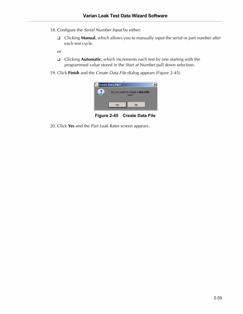
21. Click Finish and the Create Data File dialog appears (Figure 2-26).
Figure 2-26 Create Data File
22. Click Yes and the Part Leak Rates screen appears.
2-22

Varian Leak Test Data Wizard Software
DR
AF
T 3
/22
/07
2.3.3 Pressurized Part - Programmable Test Sequence
This test is an inside-out test type. For more information on this refer to Section A.3.2 “Pressure Testing Method (Inside-out)” on page A-5. This test is a also useful as an evacuated test part method.
To configure a pressurized part for a programmable test sequence test:
1. Click Multi Part Tester on the Home screen and Figure 2-27 appears.
Figure 2-27 Test Setup
2. Click either:
❑ Existing Part and click Next and Figure 2-28 appears.
Figure 2-28 Load Test Setup
or
❑ New Part and proceed to step 5.
2-23

Varian Leak Test Data Wizard Software D
RA
FT
3/2
2/0
7
3. Click Load and Figure 2-29 appears.
Figure 2-29 Save Dialog Box
4. Navigate to the required directory and select a file and click Load. Figure 2-28 reappears with the fine name and path populated into the Part Library File field.
5. Click either:
❑ Edit Part and Figure 2-30 appears from which you can change the configuration of the existing part. Proceed to step 6.
Figure 2-30 Part Setup
or
❑ Next and the Final Info screen appears from which you can run the test as already configured. Proceed to step 16.
2-24

Varian Leak Test Data Wizard Software
DR
AF
T 3
/22
/07
6. Enter a Part Description, click Pressurized Part, which activates the radio buttons below, click Programmable Test Sequence and click Next and Figure 2-31 appears.
Figure 2-31 Sequencer Setup
NOTE The sequencer test does not fail a part until the end of the test. All other test fail a part immediately.
7. Configure the Time Limits by entering the Rough Time and Test Time.
NOTE Prior to the test, characterize the unit under test to get the rough and test times.
8. Click Next and Figure 2-32 appears.
Figure 2-32 Setpoints and Units
2-25

Varian Leak Test Data Wizard Software D
RA
FT
3/2
2/0
7
9. Configure the Reject Setpoint by:
❑ Using the pulldown to select the Type:
❑ Off
❑ <
❑ >
❑ Entering the reject setpoint Value. The label to the right is configured via the Leak Rate Units pulldown.
❑ Entering the Message that appears on the Part Leak Rates screen when the value is passed.
10. Repeat step 8 for Setpoint 2 and Setpoint 3. These are not often used in this test type.
11. Use the pulldown to select the Pressure Units that appear on the Part Leak Rates screen.
12. Use the pulldown to select the Leak Rate Units that appear on the Part Leak Rates screen.
13. Click Next and Figure 2-33 appears.
Figure 2-33 Save Test Setup
2-26

Varian Leak Test Data Wizard Software
DR
AF
T 3
/22
/07
14. Click Save and Figure 2-34 appears.
Figure 2-34 Save Dialog Box
15. Navigate to the required directory and select a file and click Save. Figure 2-33 reappears with the fine name and path populated into the Part Library File field.
16. Click Next and Figure 2-35 appears.
Figure 2-35 Final Information
17. Enter the Operator Name.
18. Enter the Lot.
19. Configure the Serial Number Input by either:
❑ Clicking Manual, which allows you to manually input the serial or part number after each test cycle.
or
❑ Clicking Automatic, which increments each test by one starting with the programmed value stored in the Start at Number pull down selection.
20. Click Finish and the Create Data File dialog appears (Figure 2-36).
2-27

Varian Leak Test Data Wizard Software D
RA
FT
3/2
2/0
7
Figure 2-36 Create Data File
21. Click Yes and the Part Leak Rates screen appears.
2.3.4 Pressurized Part - Location/Accumulation Test Sequence
This is a high pressure/sniffer application test type.
This test uses the power probe and requires that the leak detector auto sequencer be off.
To configure a pressurized part for a location/accumulation test sequence test:
NOTE Varian recommends that the leak detector be locked into High Pressure Test for this application (Located under Menus - Leak Rate Ranging - High Pressure Test on/off).
1. Click Multi Part Tester on the Home screen and Figure 2-37 appears.
Figure 2-37 Test Setup
2-28

Varian Leak Test Data Wizard Software
DR
AF
T 3
/22
/07
2. Click either:
❑ Existing Part and click Next and Figure 2-38 appears.
Figure 2-38 Load Test Setup
or
❑ New Part and proceed to step 5.
3. Click Load and Figure 2-39 appears.
Figure 2-39 Save Dialog Box
4. Navigate to the required directory and select a file and click Load. Figure 2-38 reappears with the fine name and path populated into the Part Library File field.
5. Click either:
❑ Edit Part and Figure 2-40 appears from which you can change the configuration of the existing part. Proceed to step 6.
2-29

Varian Leak Test Data Wizard Software D
RA
FT
3/2
2/0
7
Figure 2-40 Part Setup
or
❑ Next and the Final Info screen appears from which you can run the test as already configured. Proceed to step 16.
6. Enter a Part Description, click Pressurized Part, which activates the radio buttons below, click Location/Accumulation and click Next and Figure 2-41 appears.
Figure 2-41 Setpoints and Units
7. Configure the Reject Setpoint by:
❑ Using the pulldown to select the Type:
❑ Off
❑ <
❑ >
2-30

Varian Leak Test Data Wizard Software
DR
AF
T 3
/22
/07
❑ Entering the reject setpoint Value. The label to the right is configured via the Leak Rate Units pulldown.
❑ Entering the Message that appears on the Part Leak Rates screen when the value is passed.
8. Repeat step 7 for Setpoint 2 and Setpoint 3. These fields are rarely used for this test type.
9. Use the pulldown to select the Pressure Units that appear on the Part Leak Rates screen.
10. Use the pulldown to select the Leak Rate Units that appear on the Part Leak Rates screen.
11. Click Next and Figure 2-42 appears.
Figure 2-42 Pressure Setup
The Pressure Setup is useful to track for clogged probes or for a problem the sniffing line in a power probe.
12. Configure the Pressure Setpoint by:
❑ Using the pulldown to select the Type:
❑ Off
❑ <
❑ >
❑ Enter a pressure setpoint Value for either a < or > condition.
13. Enter a Message that appears on the Part Leak Rates screen when the pressure setpoint value is activated. For example, Clogged Probe ... Check.
2-31

Varian Leak Test Data Wizard Software D
RA
FT
3/2
2/0
7
14. Click Next and Figure 2-43 appears.
Figure 2-43 Test Time
15. Configure the Test Time Limit by clicking either:
❑ Manual, which allows you to control the test from the Part Leak Rates screen buttons: Start or Stop.
or
❑ Clicking Automatic, which activates the time fields to the right. Enter a time and click Next and Figure 2-44 appears.
Figure 2-44 Final Information
16. Enter the Operator Name.
17. Enter the Lot.
2-32
Varian Leak Test Data Wizard Software
DR
AF
T 3
/22
/07
18. Configure the Serial Number Input by either:
❑ Clicking Manual, which allows you to manually input the serial or part number after each test cycle.
or
❑ Clicking Automatic, which increments each test by one starting with the programmed value stored in the Start at Number pull down selection.
19. Click Finish and the Create Data File dialog appears (Figure 2-45).
Figure 2-45 Create Data File
20. Click Yes and the Part Leak Rates screen appears.
2-33
Varian Leak Test Data Wizard Software D
RA
FT
3/2
2/0
7
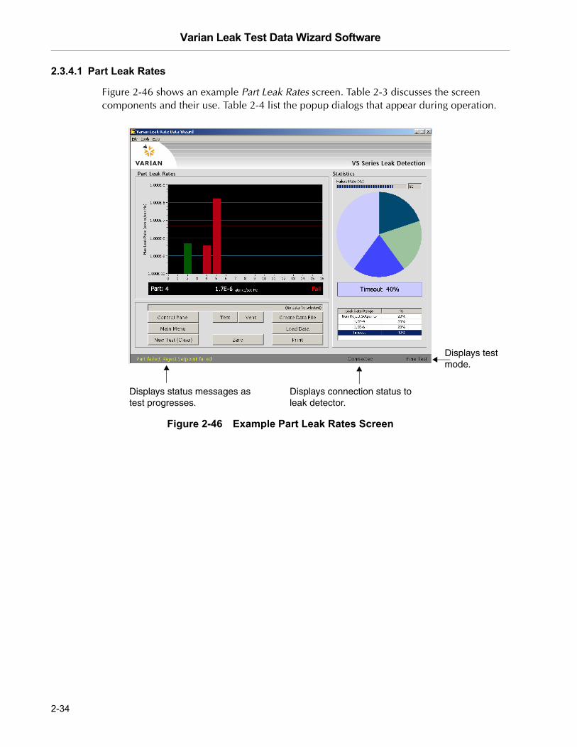
2.3.4.1 Part Leak Rates
Figure 2-46 shows an example Part Leak Rates screen. Table 2-3 discusses the screen components and their use. Table 2-4 list the popup dialogs that appear during operation.
Figure 2-46 Example Part Leak Rates Screen
Displays status messages as test progresses.
Displays connection status to leak detector.
Displays test mode.
2-34

Varian Leak Test Data Wizard Software
DR
AF
T 3
/22
/07
Table 2-3 Part Leak Rates Screen Components
Item Description
Graphs
Bar Graph body Shows the test results in log form.
Graph text Lists the Part under test, the He pressure level and gives a Pass/Fail indication.
Failure Rate (%) Overall failure rate for the test run. Lumps all failure types together. The number to the right represent the total failure rate.
Pie Chart Results of each test appear as a percentage of decades of leak rate range.
Leak Rate Range and % list Lists each decade of leak rate range. Click an item to activate it in the graph.
Buttons
Control Panel Opens the Control Panel (see Section 2.3.4.2 “Control Panel” on page 2-38).
Main Menu Returns you to the Home screen. If the system is in test, the Exit to Main Menu? dialog appears. Click:
❑ Yes to exit testing; all unsaved data is lost.❑ No to cancel and continue testing.
New Test Returns you to the Test Setup screen. If the system is in test, the Quit Current Test? dialog appears. Click:
❑ Yes to exit testing; all unsaved data is lost.❑ No to cancel and continue testing.
Test Engages the test mode until another button is clicked.
Vent Engages the vent mode until another button is clicked.
Zero Zeroes the leak detector.
Create Data File Opens a Save As dialog to save the data file (.ptest).
Do this immediately after the Part Leak Rates screen appears so as to not lose data
2-35

Varian Leak Test Data Wizard Software D
RA
FT
3/2
2/0
7
NOTE During a sniffing Location Accumulation test the leak detector is always in Test mode (Figure 2-47). Click:
Press start for leak locating/sniffing. This starts the test cycle.
Stop to use manual mode to stop the test. This stops the test at the value programmed in the Test Time Setup screen.
Load Data Opens the Select a Data File dialog to open an existing chart recorder file (.plb) for use in the present session. If there is a file open the View Part Test File dialog appears. Click:
❑ Yes to exit testing; all unsaved data is lost.❑ No to cancel and continue testing.
Print Opens a standard print dialog to print the chart or results to a printer.
Statistics
Failure Rate Broken into two parts:
❑ Power bar - displays the present failure rate as it devel-ops (%). The text filed to the right lists the failure per-centage rate numerically.
❑ Pie chart - displays the leak rate range as it develops (%).
Leak Rate Range text Displays the current leak rate range. This turns red on failure.
Leak Rate Range List the results of the recent tests. Click a Leak Rate Range item to display it in the graph.
Table 2-3 Part Leak Rates Screen Components (Continued)
Item Description
2-36

Varian Leak Test Data Wizard Software
DR
AF
T 3
/22
/07
Figure 2-47 Location Accumulation Sniffing Test
Table 2-4 Part Leak Rates Message Dialogs
Item Description
Indicates that the part under test has not reached the desired Helium background level, within the specified time limit. Appears for the Evacuated Part Tester only.
Indicates that the background He level is still not sufficient to begin testing. Venting before this disappears or before any Apply Helium message disappears causes a reject setpoint error. Click OK, resolve problem and retest. Appears for the Evacuated Part Tester only.
2-37
Varian Leak Test Data Wizard Software D
RA
FT
3/2
2/0
7
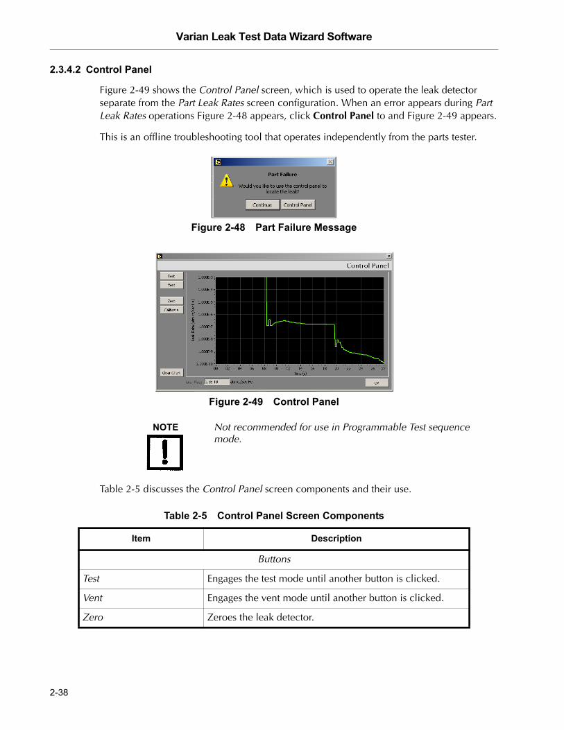
2.3.4.2 Control Panel
Figure 2-49 shows the Control Panel screen, which is used to operate the leak detector separate from the Part Leak Rates screen configuration. When an error appears during Part Leak Rates operations Figure 2-48 appears, click Control Panel to and Figure 2-49 appears.
This is an offline troubleshooting tool that operates independently from the parts tester.
Figure 2-48 Part Failure Message
Figure 2-49 Control Panel
NOTE Not recommended for use in Programmable Test sequence mode.
Table 2-5 discusses the Control Panel screen components and their use.
Table 2-5 Control Panel Screen Components
Item Description
Buttons
Test Engages the test mode until another button is clicked.
Vent Engages the vent mode until another button is clicked.
Zero Zeroes the leak detector.
2-38

Varian Leak Test Data Wizard Software
DR
AF
T 3
/22
/07
Calibrate Calibrates the leak detector external leak. A Confirm Calibration dialog appears. Click:
❑ Yes to proceed.❑ No to cancel and continue testing.
Clear Chart Clears the display area, empties the data in the buffer
OK Closes the Control Panel and reopens the Part Leak Rates screen.
Graph
Graph body Shows the test results in real time in either log or linear form, as dictated.
Graph text Lists the part under test, indicates the leak or pressure level and gives a Pass/Fail indication.
Leak Rate text Displays the current leak rate range. This turns red on failure.
Table 2-5 Control Panel Screen Components (Continued)
Item Description
2-39

Varian Leak Test Data Wizard Software D
RA
FT
3/2
2/0
7
This page intentionally left blank.

Varian Leak Test Data Wizard Software
DR
AF
T 3
/22
/07
Appendix A. Introduction to Leak Detection
A.1 Leak Testing—Why is it Needed?
Helium is a superior choice of tracer gas used to find leaks for a multitude of reasons. Helium is:
❑ Non-toxic
❑ Inert and non-condensable
❑ Normally not present in the atmosphere at more than trace amounts
❑ Relatively inexpensive
❑ Readily passes through leaks due to its small atomic size
❑ Non-flammable
❑ Available in various size cylinders
❑ Available in purities appropriate for medical usage
The only molecule smaller than Helium (mass 4) is Hydrogen (mass 2), which is not inert. Helium is much lighter than the next heavier inert molecule, Neon (mass 20) which is much more expensive. Helium is present at a concentration of only 5 ppm in normal atmospheric conditions.
A.2 Varian's Helium Leak Detection Technologies
A Mass Spectrometer Leak Detector (MSLD) is a complete system for locating and/or measuring the size of leaks into or out of a device or a container. This method of leak detection is initiated when a tracer gas, helium, is introduced to a test part that is connected to the MSLD system. The helium leaking from the test part diffuses through the system, its partial pressure is measured, and results are displayed on a meter.
The MSLD operating principle consists of ionization of the gases in a vacuum and their acceleration across a voltage drop and a magnetic field (Figure A-1). The helium ions are separated and collected, and the resulting ion current is amplified and indicated on the meter or display.
A mass spectrometer leak detector consists of the following components:
❑ A spectrometer tuned to detect the mass of helium
❑ A vacuum system to maintain adequately low pressure in the spectrometer
❑ A mechanical pump(s) to evacuate the part to be tested
A-1

Varian Leak Test Data Wizard Software D
RA
FT
3/2
2/0
7
❑ Valves that enable the various stages of the leak detection cycle, from evacuation, to test, to venting
❑ Amplifier and readout instrumentation that monitors spectrometer output signal
❑ Electrical power supplies and controls that sequence valve’s, protective circuits, etc.
❑ Fixturing that attaches the part to be leak-tested to the leak testing equipment
Figure A-1 Magnetic Separation Principle
Our SIPD family of products is also sensitive to helium and is based on a patented technology called Selective Ion Pump Detection (Figure A-2). The sensor technology incorporates an ion pump connected to a quartz capillary tube and maintained under high vacuum. This membrane is heated with a coiled platinum filament. Once heated, the membrane becomes permeable to helium. As the partial pressure of helium in the ion pump increases, so does the current draw of the ion pump. This current is proportional to the pressure and is therefore representative of the helium at the test probe of the instrument.
A selective ion pump detector consists of the following:
❑ An ion pump and controller
❑ A permeable quartz capillary
❑ A heater coil that surrounds the quartz capillary
❑ Electronics to process the signal
❑ Display for access to leak rate and other unit functions
A-2

Varian Leak Test Data Wizard Software
DR
AF
T 3
/22
/07
Figure A-2 Selective Ion Pump Detector
A.3 Methods of Leak Testing
There are many different ways to leak test parts using helium as a tracer gas. In general, the leak detection method is selected based on the actual working conditions of the part being tested. It is recommended that during leak testing, the same pressure differential be maintained and in the same direction as exists during the actual use of the part. For example, a vacuum system is tested with a vacuum inside the chamber, while a compressed air cylinder should be tested with a high pressure inside the cylinder.
There are two general concerns when leak testing. One is the location of leaks and the other is the measurement of the total leakage rate of the part, as some leakage may be acceptable. In many cases, parts may be first tested to determine if they pass an acceptable level, and if not, the part may be taken off line and subjected to a second test with the intent of locating the leak. Additionally, many parts may be tested in batches. If a batch fails, the individual parts in that batch may then be tested separately to identify the leaking part(s).
A-3

Varian Leak Test Data Wizard Software D
RA
FT
3/2
2/0
7
A.3.1 Vacuum Testing Method (Outside-in)
The part to be tested is evacuated with a separate pumping system for large volumes, or with just the leak detector itself. When the appropriate cross over pressure has been reached, the leak detector is valved-in or transfers into test and the part is tested using one of the following methods:
A.3.1.1 Locating Leaks
To pinpoint the location of the leak(s) (but not measure the total leakage rate), helium is administered to the suspected leak sites of the part using a spray probe with an adjustable flow (Figure A-3).
Figure A-3 Locating Leaks: Outside In
A.3.1.2 Measuring Leaks
To determine the total quantity of leakage (but not the number or location of leaks), the part is connected to the leak detector and shrouded by a helium environment. This helium environment can be contained in many methods ranging from a simple plastic bag to more complex bell jar arrangements (Figure A-4).
Figure A-4 Measuring Leaks: Outside In
A-4

Varian Leak Test Data Wizard Software
DR
AF
T 3
/22
/07
A.3.2 Pressure Testing Method (Inside-out)
In this technique, the part is pressurized with helium or a mixture of helium and air, and tested by one of the following methods.
A.3.2.1 Measuring Leaks
To determine the total quantity of leakage (but not the number or location of leaks), the part is pressurized with helium (or a mixture of helium and air or nitrogen). This can be done by bombing or backfilling small hermetically sealed parts. Larger parts can be actively pressurized using a hose or tubing to deliver the helium. The part is placed in a volume that is then evacuated by the leak detector. All the helium escaping from the part is captured and quantified (Figure A-5).
Figure A-5 Measuring Leaks: Inside Out
A.3.2.2 Locating Leaks
To pinpoint the location of the leak(s) (but not measure the total leakage), the likely potential leak sites of the part are scanned using a Sniffer Probe connected to the inlet of the leak detector (Figure A-6).
Figure A-6 Locating Leaks: Inside Out
A-5

Varian Leak Test Data Wizard Software D
RA
FT
3/2
2/0
7
A.3.2.2.1 Accumulation Testing Method
This method can both locate and quantify leaks. Some type of shroud or hood is placed in such a manner as to envelop a potential leak site. A certain amount of time is given to allow leaking helium to accumulate in the shrouded area, increasing the helium concentration. The leak detector is then valved-in to the shrouded volume. If many potential leak sites exist in a manifold or if many parts are to be tested at the same time, they can be sequentially valved-in to determine which site is leaking (Figure A-7).
Figure A-7 Accumulation: Inside Out
A.3.3 System Leak Test Methods
Systems, like individual parts, should be tested with the same pressure differential and in the same direction as in actual use. Therefore, systems that are under vacuum while in operation should be leak tested under vacuum, while pressurized systems should be charged with helium to a pressure similar to operational conditions when possible.
A.3.3.1 Vacuum Systems
In general, vacuum systems are tested with a portable leak detector. Typically the leak detector is connected by means of a tee connected in between the foreline of the high vacuum pump and the inlet of its backing pump. A system should be capable of maintaining a foreline pressure low enough to operate the leak detector at this location. Helium is supplied to potential leak site using a spray probe or bagging suspected areas. If a leak exists, helium enters the system and rapidly diffuses through it. The leak detector should respond within several seconds or less. Leak detector sensitivity is diminished in systems with large backing pumps. If a system is using a cryopump as a high vacuum pump, it must be valved off before helium is introduced as cryopumps have limited helium pumping capacity (Figure A-8).
A-6

Varian Leak Test Data Wizard Software
DR
AF
T 3
/22
/07
Figure A-8 Vacuum System
A.3.3.2 Pressurized Systems
Many different types of pressurized systems also need to be leak-free. These systems can be charged with helium or some mixture of helium and another gas such as nitrogen. If a diluted helium mixture is used, the helium signal is diminished proportionally. For example, if a mixture of 10% helium and 90% nitrogen is used, the signal reads 10% of the actual value of the leak, or a decade lower. This may be acceptable in many cases as system leak checking is usually to locate rather than quantify leaks. Once the system has been charged with an appropriate amount of helium, leak checking can be performed by means of a sniffer probe, or by bagging suspected leak sites so that leaking helium accumulates to a detectable level.
A-7

Varian Leak Test Data Wizard Software D
RA
FT
3/2
2/0
7
A.4 Typical Leak Detection Applications
A.4.1 Quality Control of Production Parts and Assemblies
The detection and location of leaks is critical in the production of many products from individual components, to subassemblies, to completed systems. In many of these cases, it is as important to know the size or rate of the leak, as it is the location. Whether quantitative or qualitative testing is required, our leak detectors help assure the leak integrity of your parts or assemblies. Some examples include:
Evacuated parts and assemblies
❑ Hermetically sealed electronic packages
❑ Valves and manifolding
❑ Feedthroughs/glass-to-metal seals
❑ Vacuum vessels and systems
Pressurized parts and assemblies
❑ Air conditioning and refrigeration assemblies
❑ Radiators, heat exchangers, and condensers
❑ Brake, fuel, and hydraulic lines
❑ Gas tanks
❑ Food storage tanks and packaging
❑ Body implantable medical devices
❑ High purity piping
A.4.2 Maintenance of Systems
Many vacuum process tools in fabs of all types require occasional leak checking. This may be part of a preventative maintenance schedule or in the event of an unexpected failure. Downtime in either case must be minimized. A rugged, dependable, fast starting leak detector is essential to maximize up time of production tools. Varian VS Series portable leak detectors keep industry moving. Examples of some of these applications are:
Vacuum process equipment or tools
❑ Vacuum furnaces
❑ Vacuum coaters
❑ Beam lines
❑ Electron beam and ion beam process equipment
❑ Analytical Instruments
A-8

Varian Leak Test Data Wizard Software
DR
AF
T 3
/22
/07
❑ Semiconductor process tools
❑ Laser process equipment
Pressurized systems
❑ Power Plants
❑ Underground tanks, cables, and pipes
❑ High purity gas handling systems
❑ Bioreactors and fermenters
❑ Liquid gas manufacturing facilities
❑ Fuel tanks and bladders
A.4.3 System Integrated Leak Detection
Manufacturers of large, complex systems may choose to integrate into those systems a component leak detector that can facilitate the on-going maintenance of leak-free integrity, thereby providing additional value to their customers. The Varian 990CLD and 990dCLDII provide the necessary elements for flexible integration of leak detection capability into a large system. Examples of these systems are:
❑ Semiconductor process equipment
❑ PVD/CVD equipment
❑ E-beam and ion beam processing equipment
A.4.4 Mass Produced Parts
Some manufacturing processes require the integration of a leak-checking device into a multi-step process, usually with very high production rates. Component leak detectors are designed specifically for these applications in which a vacuum system and the control electronics may be mounted separately. The Varian 990CLD and 990dCLDII offer the ultimate flexibility in a helium mass spectrometer leak detection system. The flexibility, ruggedness and rapid response time of these units allows for accurate, repeatable, high volume leak testing in demanding production environments. Some examples include:
High Volume Manufactured Parts
❑ Automotive fuel systems
❑ Automotive brake components
❑ Cooling and refrigeration system components
❑ Medical devices
❑ Automotive airbag components
❑ Tire and wheel assemblies
A-9

Varian Leak Test Data Wizard Software D
RA
FT
3/2
2/0
7
Portable Sniffing Applications
Some applications require operators or technicians to look for leaks from a ladder, outdoors, above or below ground, or in a densely constructed industrial facility or power plant. In these cases, a mobile cart-mounted MSLD may not be practical. A truly portable unit such as the PHD-4 is required. Some examples of such applications are:
❑ Aircraft manufacturing and maintenance
❑ Power generating plants
❑ Pressurized pipelines
❑ Bioreactors and fermenters
❑ Petrochemical plants and refineries
❑ Underground tanks
❑ Large condensers or heat exchangers
A-10

Varian Leak Test Data Wizard Software
DR
AF
T 3
/22
/07
Appendix B. Reports
B.1 Data Recorder Reports
Figure B-1 and Figure B-2 are the printed reports for the Data Recorder operations. Figure B-1 shows the trace produced during the test on the Operations screen.
Figure B-1 Data Recorder - Operations Screen Printout
B-1
Varian Leak Test Data Wizard Software D
RA
FT
3/2
2/0
7
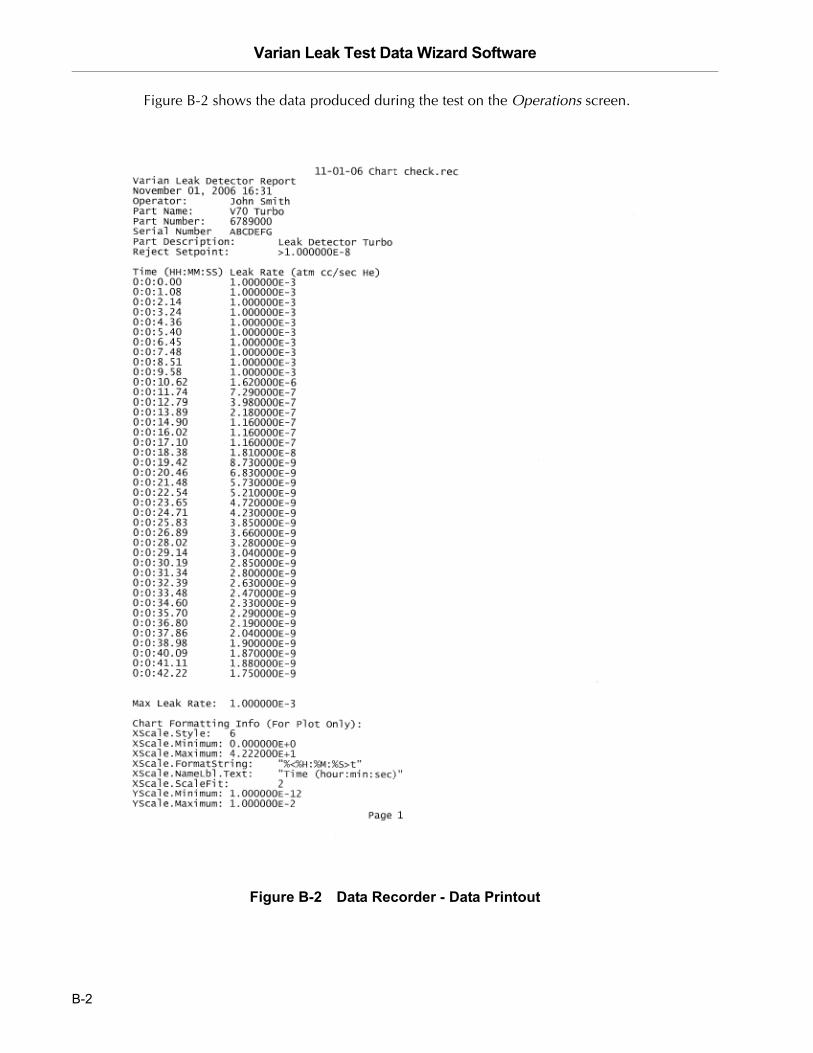
Figure B-2 shows the data produced during the test on the Operations screen.
Figure B-2 Data Recorder - Data Printout
B-2
Varian Leak Test Data Wizard Software
DR
AF
T 3
/22
/07
B.2 Parts Test Reports
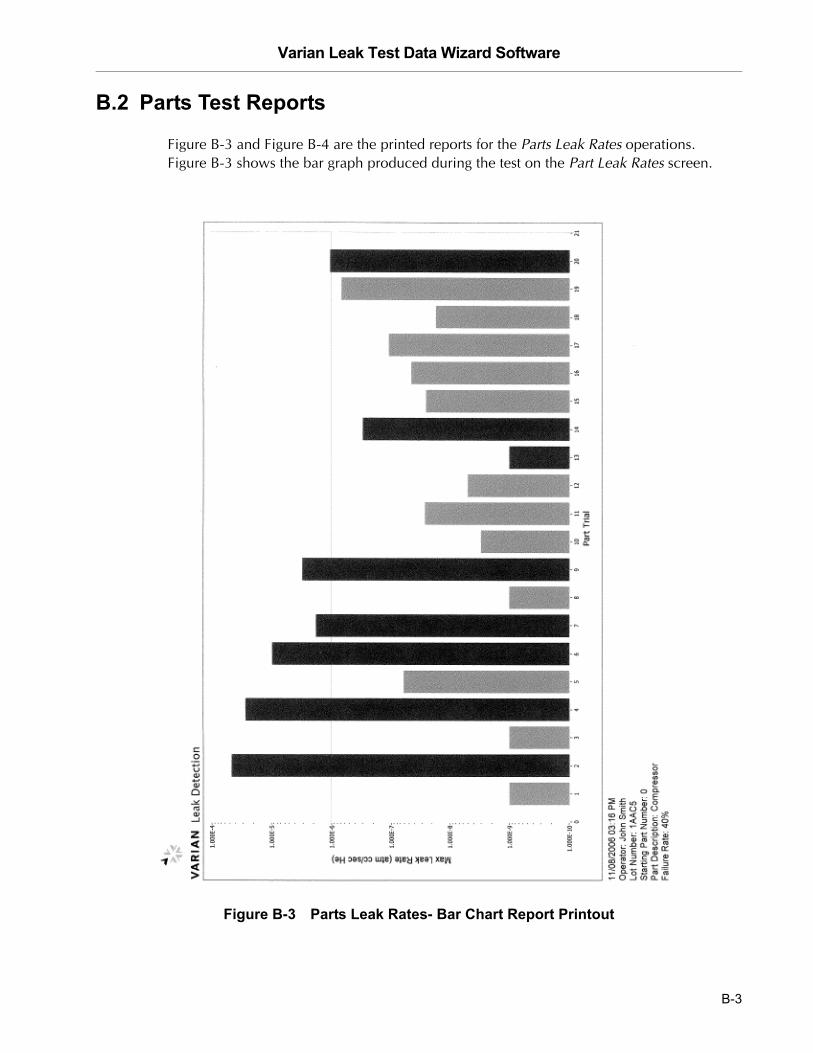
Figure B-3 and Figure B-4 are the printed reports for the Parts Leak Rates operations. Figure B-3 shows the bar graph produced during the test on the Part Leak Rates screen.
Figure B-3 Parts Leak Rates- Bar Chart Report Printout
B-3

Varian Leak Test Data Wizard Software D
RA
FT
3/2
2/0
7
Figure B-4 shows the data produced during the test on the Part Leak Rates screen.
Figure B-4 Parts Leak Rates- Data Printout
B-4


Sales and Service Offices
12/04
Canada Central coordination through:Varian, Inc.121 Hartwell AvenueLexington, MA 02421USATel: (781) 861 7200Fax: (781) 860 5437Toll Free: (800) 882 7426
China Varian Technologies - BeijingRoom 1201, Jinyu MansionNo. 129A, Xuanwumen XidajieXicheng DistrictBeijing 1000031P.R. ChinaTel: (86) 10 6608 1031Fax: (86) 10 6608 1541
France and Benelux Varian s.a.7 avenue des TropiquesZ.A. de Courtaboeuf – B.P. 12Les Ulis cedex (Orsay) 91941FranceTel: (33) 1 69 86 38 13Fax: (33) 1 69 28 23 08
Germany and Austria Varian Deutschland GmbHAlsfelder Strasse 6Postfach 11 14 3564289 DarmstadtGermanyTel: (49) 6151 703 353Fax: (49) 6151 703 302
India Varian India PVT LTD101-108, 1st Floor1010 Competent House7, Nangal Raya Business CentreNew Delhi 110 046IndiaTel: (91) 11 5548444Fax: (91) 11 5548445
Italy Varian, Inc.Via F.lli Varian, 5410040 Leini, (Torino)ItalyTel (39) 011 997 9 111Fax (39) 011 997 9 350
Japan Varian, Inc.Sumitomo Shibaura Building, 8th Floor4-16-36 ShibauraMinato-ku, Tokyo 108JapanTel: (81) 3 5232 1253Fax: (81) 3 5232 1263
Korea Varian Technologies Korea, Ltd.Shinsa 2nd Building 2F966-5 Daechi-dong Kangnam-gu, SeoulKorea 135-280Tel: (82) 2 3452 2452Fax: (82) 2 3452 2451
Mexico Varian S.A.Concepcion Beistegui No 109Col Del ValleC.P. 03100Mexico, D.F.Tel: (52) 5 523 9465Fax: (52) 5 523 9472
Russia Central coordination through:Varian, Inc.via F.lli Varian 5410040 Leini, (Torino)ItalyTel: (39) 011 997 9 252Fax: (39) 011 997 9 316
Taiwan Varian Technologies Asia Ltd. 18F-13 No.79, Hsin Tai Wu RoadSec. 1, Hsi Chih, Taipei HsienTaiwan, R.O.C.Tel: (886) 2 2698 9555Fax: (886) 2 2698 9678
UK and Ireland Varian Ltd.28 Manor RoadWalton-On-ThamesSurrey KT 12 2QFEnglandTel: (44) 1932 89 8000Fax: (44) 1932 22 8769
United States Varian, Inc.121 Hartwell AvenueLexington, MA 02421USATel: (781) 861 7200Fax: (781) 860 5437
Other Countries Varian, Inc.
Via F.lli Varian 5410040 Leini, (Torino)ItalyTel: (39) 011 997 9 111Fax: (39) 011 997 9 350
Customer Support and Service:
North AmericaTel: 1 (800) 882-7426 (toll-free)[email protected]
EuropeTel: 00 (800) 234 234 00 (toll-free)[email protected]
JapanTel: (81) 3 5232 1253 (dedicated line)[email protected]
KoreaTel (82) 2 3452 2452 (dedicated line)[email protected]
TaiwanTel: 0 (800) 051 342 (toll-free)[email protected]
Worldwide Web Site, Catalog and On-line Orders:www.varianinc.com
Representatives in most countries
Sales and Service Offices