variable displacement pumps - hydroleduc leduc... · designed for open loop hydraulic circuits, ......
TRANSCRIPT

DELTASAE
Serie
v a r i a b l e d i s p l a c e m e n t p u m p s
m��� i� ������

D E LTA s e r i e s p u m p sx x x
HYDRO LEDUCHead office and factoryBP 9F-54122 AZERAILLES (FRANCE)Tél. +33 (0)3 83 76 77 40Fax +33 (0)3 83 75 21 58
C o n t e n t s
■■ Range and characteristics . . . . . . . . . . . . . . . . . . . . . . 1
■■ Dimensions . . . . . . . . . . . . . . . . . . . . . . . . . . . . . . . . . 2
■■ Performance . . . . . . . . . . . . . . . . . . . . . . . . . . . . . . . . . 5
■■ Control devices . . . . . . . . . . . . . . . . . . . . . . . . . . . . 4 to 8
■■ Delta pump with constant torque LS control . . . . . . . . . 9
■■ Fittings . . . . . . . . . . . . . . . . . . . . . . . . . . . . . . . . . . . . 10
■■ Shaft sealing . . . . . . . . . . . . . . . . . . . . . . . . . . . . . . . 11
■■ Installation and start-up recommendations . . . . . . . . . 12
■■ The complete LEDUC product range . . . . . . . . . . . . . . 13
Designed for open loop hydraulic circuits, the DELTA range of variable displacement pumps allow optimized performance for a given appli-cation. The flow supplied by the pump is automatically regulated according to the hydraulic load. This guarantees:
– minimized energy consumption, – minimized heating of fluid, – reduced noise levels.
Built on 40 years know-how and experience, the DELTA pumps are the result of advanced development work and analysis on the needs of the hydraulic end-user. The DELTA pumps satisfy the needs of the more demanding users. The pump provides:
– long service life, – no pressure pulsations, – low noise level, – exceptional power to weight ratio, – high outlet pressure, – easy start-up thanks to good self-priming and suction characteris-tics.
Displacements in production include 40, 60, 75 and 92 cc/rev. Depending on the application, displacements of 120 and 130 cc/rev can be delivered on request.
Under development

1■■ Setting pump maximum displacement
The DELTA pumps from 40cc to 92cc are made as standard to be able to use the setting screw. The pump displacement can thus be adjusted to exactly what is needed.
■■ How to use the setting screw
Unscrew 1 completely, loosen 3 and screw 2 to the required displacement.See figure above.
For DELTA 92 to 40: 1 turn of the screw changes the displacement by 8 cc.
��
50
60
70
80
90
100
110
120
0
10
20
30
40
16 18 20 22 24 26 28 30 32 34 36 38
1 2 3
Back of the pump
max displacement
number of revolutions1 turn = 8 cc
setting screw of maximum flow
DELTA 40: can be set from 40 to 25 cc/revDELTA 60: can be set from 60 to 35 cc/revDELTA 75: can be set from 75 to 55 cc/revDELTA 92: can be set from 92 to 70 cc/rev
Pump ReferenceDirection of
rotationMax
displacement (cc)
Maximum operating pressure
(bar)
Maximum peak pressure (intermittent
5%)
Max operating pressure at flow
cancelation (bar)
Torque at 300 bar
(Nm)Max speed
(rpm)
Weight
(kg)
DELTA 400512370
0512375
SH
SIH40 400 420 440 220 3000 29
DELTA 600513140
0513145
SH
SIH60 400 420 440 295 2600 29
DELTA 750512340
0512345
SH
SIH75 400 420 440 410 2000 29
DELTA 920512350
0212355
SH
SIH92 380 400 420 483 1900 29
These are the references of the pump alone. When ordering, also specify the reference of the required control device. See page 4.
R a n g e a n d c h a r a c t e r i s t i c s D E LTA s e r i e s p u m p sDi
spla
cem
ent o
f the
pum
p -
cc
Dimension X mm
XDELTA 40 to DELTA 92

PumpDimensions (mm)
A B C D E F G H I J M N O P
DELTA 40 282 329 47 1025.4 h9
101.6 h8
8028.1 JS13
(bey width 6.38h9)9.5 46 62 97 146 R8
DELTA 60 to 92 282 339.1 57.1 13 31.75 h8127 h7
9535.2 JS13
(bey width 8e9)12.7 58.4 62 97 181 R10
For other shafts, please contact our Technical Department.
D E LTA s e r i e s p u m p sD i m e n s i o n s
■■ DELTA connections
(other port styles available)
2
Dimensions are given only as an indication.
O
M8
P
M
ND
FB
G HB
EB
JI
C AB
direction of rotation minimum flow pin (optional extra)
F
bleed orifice G 1/4"setting screw of maximum flowcontrol device
36
2915
28
25
36
29
15
281919
25
6.45
6.45
view from F view from F
G 1"½inlet G 3/4"
outlet
2 x M10 depth 15 to attach support device
CW CCW

■■ Flow
Flow as a function of speed and displacement of the pump.
■■ Required torque at maximum displacement
■■ Volumetric efficiency
Viscosity 100 cSt, inlet at air pressure.
P e r f o r m a n c e s D E LTA s e r i e s p u m p s
Calculating power as a function of torque
(theoretical hydraulic power) where:N = speed in rpmΔP = working pressure in barQ = flow in l/minute
C P (kW) N.m= =x 1000
N30
=
P (kW) P x Q600
=
3
■■ Ideal installation: tank above the pump
These graphs are the results of tests carried out by the HYDRO LEDUC Research Laboratory, on a specific test bench, with ISO 46 fluid at 25°C (100 cSt), a 50 mm diameter supply line 1.5 m long, and a tank with oil level at the same height as the pump.
1000
50
0
100
150
200
2000 3000 3600
92
75 60
40
GPM Q (Gpm/min.)
N (rpm)
52
39
26
13
2001005000
100
200
300
400
500
600
700
800
N.m
300 400 bar
40
60
7592
Torque
590
516
443
310
275
221
141
14
225 450 2900 4350 5800 PSI
200100090
100%
300 400 bar
efficiency at 1,500 rpm
1450 2900 4350 5800 PSI

x x x
4
x x xD E LTA s e r i e s p u m p sC o n t r o l d e v i c e s
■■ PC - Constant Pressure
149
operating pressure P
flow Q
direction of rotationT (drain G 3/8")
connection for pressure gauge
setting screw of maximum flowsetting screw (R1)
setting screw (R1)
■■ Reference Designation Weight (kg)
PC 0519180 Constant Pessure 1.10
PCD 0519070 remote control constant pressure 1.10
PCDM0519340
+ adjustable displacement screw 0512602
constant pressure with minimum flow control 2.50
LS 0515333 flow-pressure regulation 1.10
LSD 0519080 remote control flow-pressure regulation 1.10
KPF 0520693 plate + fixation screw 0.30
The pressure control maintains constant pressure in the hydraulic system.As soon as pressure reaches the level set on the control, the flow of the pump automatically regulates itself according to what the application requires. This minimizes system heat and energy for those applications requiring pres-sure to be held constant.
Examples: - hydraulic press, - compression mold, - manufacturing of composites…
Important note !
otherwise specified by
customer:
PC will be set
at 100 bar
R1
P
T (drain G 3/8")
safety valve of the circuit
5
x x xD E LTA s e r i e s p u m p sC o n t r o l d e v i c e s
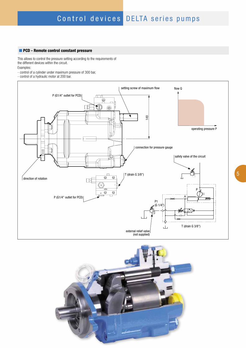
■■ PCD - Remote control constant pressure
149
flow Q
operating pressure P
direction of rotation
setting screw of maximum flow
P (G1/4" outlet for PCD)
connection for pressure gauge
P (G1/4" outlet for PCD)
This allows to control the pressure setting according to the requirements of the different devices within the circuit. Examples: - control of a cylinder under maximum pressure of 300 bar, - control of a hydraulic motor at 200 bar.
P1 (G 1/4")
P
A
T (drain G 3/8")
external relief valve (not supplied)
T (drain G 3/8")
safety valve of the circuit
C o n t r o l d e v i c e s D E LTA s e r i e s p u m p s
6
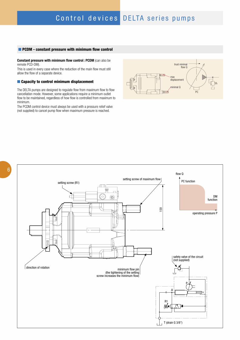
■■ PCDM - constant pressure with minimum flow control
159
PC function
DMfunction
flow Q
operating pressure P
direction of rotation minimum flow pin(the tightening of the setting
screw increases the minimum flow)
setting screw of maximum flowsetting screw (R1)
Constant pressure with minimum flow control : PCDM (can also be remote PCD-DM).This is used in every case where the reduction of the main flow must still allow the flow of a separate device.
■■ Capacity to control minimum displacement
The DELTA pumps are designed to regulate flow from maximum flow to flow cancellation mode. However, some applications require a minimum outlet flow to be maintained, regardless of how flow is controlled from maximum to minimum.The PCDM control device must always be used with a pressure relief valve (not supplied) to cancel pump flow when maximum pressure is reached.
max displacement
minimal Q
trust minimal flow Q
PC
A
R1
P
T (drain G 3/8")
safety valve of the circuit (not supplied)

D E LTA s e r i e s p u m p sC o n t r o l d e v i c e s
E
LS
7
■■ LS - Flow–pressure control
149
flow Q
operating pressure P
direction of rotationT (drain G 3/8")
setting screw of maximum flow
stand-by setting RX (set at thefactory to: 30 bar; can be set at up to 40 bar; please contact us)
cancellation pressure R1 setting (maximum 400 bar)
connection for pressure gauge
LS (G1/4")
■■ Contrôle Q et P (LS : Load-Sensing)
This control device (LS) enables the flow and the maximum output pressure of the pump to be controlled continuously.
From this, it is easy to imagine all possible combinations: - large flow and small pressure, - high pressure and small flow.
This type of control can be fitted with remote control to control pressure and flow.
■■ Principle of flow-pressure control
The flow of the pump Q through the application E must ensure a constant ΔP set at 20 to 30 bar.S: surface of the cross section of oil passage
This ΔP is proportional to:
soit ΔP = f ( QS )Q
S
Each time the ΔP varies due to a change at E, the pump will vary its flow Q to suit and to ensure:ΔP = constant.E can be: - a flow control, - a proportional valve, - a simple restriction device.
■■ Principle of pressure control
Principe de régulation de pression
Important note !
otherwise specified by
customer:
PC will be set at 100 bar
stand-by at 30 bar
R1 RX
LS
PA
T (drain G 3/8")
proportional valve
LS (G1/4")

8
D E LTA s e r i e s p u m p sC o n t r o l d e v i c e s
■■ LSD - Remote control flow-pressure regulation
165
flow Q
operating pressure P
direction of rotation
setting screw of maximum flow
stand-by setting RX (set at thefactory to: 30 bar; can be set at up to 40 bar; please contact us)
cancellation pressure R1 setting (maximum 400 bar)
connection for pressure gauge
LS (G1/4")
réglage PC à distance (G1/4")
■■ Flow-pressure regulation
This control device means flow can be controlled continuously with remote control pressure compensation (LSD).
The pressure is controlled via an external pressure relief valve (not supplied).
■■ Principle of flow-pressure control
The flow of the pump Q through the application E must ensure a constant ΔP set at 20 to 30 bar.S: surface of the cross section of oil passage
This ΔP is proportional to:
soit ΔP = f ( QS )Q
S
Each time the ΔP varies due to a change at E, the pump will vary its flow Q to suit and to ensure:ΔP = constant.E can be: - a flow control, - a proportional valve, - a simple restriction device.
P1(G1/4")
P
A
RX
LS
T (drain G 3/8")
proportional valve
LS (G1/4")
external relief valve (not supplied)
T (drain G 3/8")

9
D E LTA s e r i e s p u m p sC o n t r o l d e v i c e s
■■ DELTA pump with constant torque LS control
DescriptionThis constant torque control for the DELTA pumps ensures that the power installed in the circuit cannot be exceeded, whilst still allowing control of flow and of maximum circuit pressure. The constant torque LS control is available for DELTA pumps of 40, 60, 75, 92 and 92cc.The dimensions of the constant torque LS control are the same as for the standard LS valve.
Warning: this control device can only be associated with a DELTA pump provided with a constant torque LS control.
PumpDirection
of rotation
Maxdisplacement
(cc)
Maximum operating
pressure (bar)
Maximum peak pressure
(intermittent 5%)
Max operating pressure t flow
cancellation (bar)
Torqueat 300 bar
(Nm)
Maxspeed (rpm)
Weight (kg)
DELTA 400521300 0521305
CW CCW
40 400 420 440 220 3000 29
DELTA 600521310 0521315
CW CCW
60 400 420 440 295 2600 29
DELTA 750521320 0521325
CW CCW
75 400 420 440 410 2000 29
DELTA 920521330 0521335
CW CCW
92 380 400 420 483 1900 29
The constant torque control on the TXV pump shaft is controlled by the Load Sensing device (flow and pressure regulation).
PrincipleThe constant torque control means “pressure x flow = constant” is perma-nently achieved. Precision is 5% to 10% around the theoretical curve. The setting is done at the factory. For each order, please stipulate the pump displacement, standby pressure, and the constant torque level required. The constant torque control is always complete with constant pressure (PC) control and flow control.
The constant torque LS control device must always be used with a pressure relief valve (not supplied) to cancel pump flow when maximum pressure is reached.
T
A
T
LS
P
0
0 50 100 150 200 250 300 350 400
20
40
60
80
100
120
140
160
180
200
P = 75kW
P = 55kWP = 47kWP = 35kWP = 22kW
Pressure (bar)
Example: graph of flow as a function of power
Flow
(l/m
in)
not supplied
Under development

10
F i t t i n g s D E LTA s e r i e s p u m p s
■■ Force on pump shaft
Fr : acceptable max radial force = 3000 N,Fa : acceptable axial force = 1600 N.
gear driveCW CCW
vue pour: optimisation de la transmission de puissance à l'arbre de la pompe
vue pour: optimisation de la transmission de puissance à l'arbre de la pompe
vue pour: optimisation de la transmission de puissance à l'arbre de la pompe
vue pour: optimisation de la transmission de puissance à l'arbre de la pompe
35/40°Fr 35/40° Fr
belt driveCW CCW
Fr Fr
■■ Optimization of the transmission of power to the shaft of the pump
■■ Inlet fittings
To be used on the inlet orifice of the DELTA pumps.
Reference A Ø B C D E F
240131 G 1"½ 40 60 17 61 77
240133 G 1"½ 50 60 17 65 82
C
A
B
D
E
Straight fittings
Reference A Ø B C D E
051523 G 1"½ 40 56 14 54
240067 G 1"½ 50 52 14 66
240066 G 1"½ 60 64 14 69
240186 G 1"½ 63,5 64 14 69
240201 G 1"½ 76.2 80 14 89
F
C
A
D
E
B
90° elbow fittings, swivel
Fa
Fr

11
S h a f t s e a l i n g D E LTA s e r i e s p u m p s
LEDUC pumps destined for truck hydraulics are all fitted with rein-forced sealing comprising:
■● two radial seals: an external seal adapted to the needs of PTOs and gear-boxes; and an internal seal adapted to the needs of hydraulic performance;■● an original protection of the pump shaft seals. This is a flexible transparent tube which avoids any entry of contaminants between the two seals, and to assure air vent of the space between the two seals.
✔ Recommendations for attaching the protective tube:■● make a siphon with the tube so as to avoid any introduction of: - dirt from road; - water or damp from high pressure washing of vehicle.■● put the end of the tube downwards, or in a place sheltered from any projections;■● fix the tube in place using a collar/clip.
✘ Avoid:■● attaching the tube to any parts which may move, this could lead to it being damaged or torn off;■● any pinching or folds in the tube when fixing it in place;■● any obturation of the end of the tube.
x x x
12
x x x
A dedicated R&D team means HYDRO LEDUC is able to adapt or create
products to meet specifi c customer requirements. Working in close
cooperation with the decision-making teams of its customers, HYDRO LEDUC optimizes
proposals based on the specifi cations submitted.
w e a r e p a s s i o n a t e a b o u t h y d r a u l i c s …
hydro-pneumatic accumulatorsBladder, diaphragm accumulators.Spherical and cylindrical accumulators.Volume capacities from 20 cc to 50 liters.Pressures up to 500 bar.Accessories for use with hydraulic accumulators.
hydraulic motors
Fixed displacement bent-axis piston motors. Models from 5 to 180 cc.Available both in ISO and SAE versions.
PAPACPAD
TXV
piston pumps for trucks
HYDRO LEDUC offers 3 types of piston pumps perfectly suited to all truck and PTO-mount applications.Fixed and variable displacement from 12 to 150 cc.
XP
Fixed displacement pumps, the W series, and variable displacement pumps, the DELTA series. High pressure capabilities within minimal size.W series: fl anges to ISO 3019/2, shafts to DIN 5480.DELTA series: SAE shafts and fl anges.
mobile and industrial pumps
micro-hydraulics This is a fi eld of exceptional HYDRO LEDUC know-how: • axial and radial piston pumps,
of fi xed and variable displacement,• axial piston micro-hydraulic motors,• micro-hydraulic units incorporating pump,
electric motors, valving, controls, etc.To users of hydraulic components which have to be housed in extremely small spaces, HYDRO LEDUC offers complete, original and reliable solutions for even the most diffi cult environments.
12
■■ The tank:
Generally, hydraulic pumps much prefer a tank above the pump.LEDUC pumps can also operate with oil level beneath the pump, for further information on such installations, please contact our Technical Department.Correct inlet conditions are between 0.8 to 2 bar absolute pressure.The tank should preferably have a separation between inlet side and return. This avoids fluid emulsion and the introduction of air into the hydraulic circuit.Ensure also that the suction is not from the very bottom of the tank, so as to protect the pump from any deposits (particles).
■■ Hosing:
Should be dimensioned to ensure flow between 0.5 and 0.8 m/second. Choose as direct a supply line as possible, avoiding sharp bends.
■■ Filtration:
HYDRO LEDUC recommends using a very clean tank, filtered during filling and with filter on air vent.The pump supply line must be cleaned (decontaminated) and the return line should be filtered as follows:F or relatively simple circuits Use a 20 micron filter on pump return line.
F or more complex circuits Ideal solution: high pressure filter between the pump and the hydraulic circuit, 10 to 20 micron filter, clogging indicator.
■■ The fluid
Use a mineral hydraulic oil with viscosity between 10 and 400 cSt. It is in this viscosity range that the pumps keep their volumetric characteristics. If you wish to use other fluids, please consult our Technical Department.Maximum temperature of fluid in the pump should not exceed 100°C.
■■ Drive and assembly recommendations
For PTO mount applications, be careful to respect the tightening recommendations in terms of pump onto PTO and PTO onto vehicle gearbox.DELTA pumps are not designed to withstand any axial load on the pump shaft. Check your installa-tion conforms to this requirement.
■■ Preparation of the pump
Before start-up, the pumps should preferably be filled with oil.
■■ Start-up
- open the supply valve if there is one; - check the valve is in “back to tank” position; - partially unscrew the output fitting; - start up at low speed, or by successive starts/stops; - retighten the output connector as soon as air bubbles have disappeared; - let the pump run for one to two minutes, and check that the flow is well established;
- check the pump is running correctly, with no vibrations nor abnormal noise; - after several hours of operation, check the tightening torque of the pump fixture to PTO.
■■ Maintenance
Some regular checks are necessary, namely: - tightening of pump to PTO; - cleanliness of fluid; - state of filter.
If you notice traces of oil in the plastic tube, it is essential to check the sealing between PTO and pump.
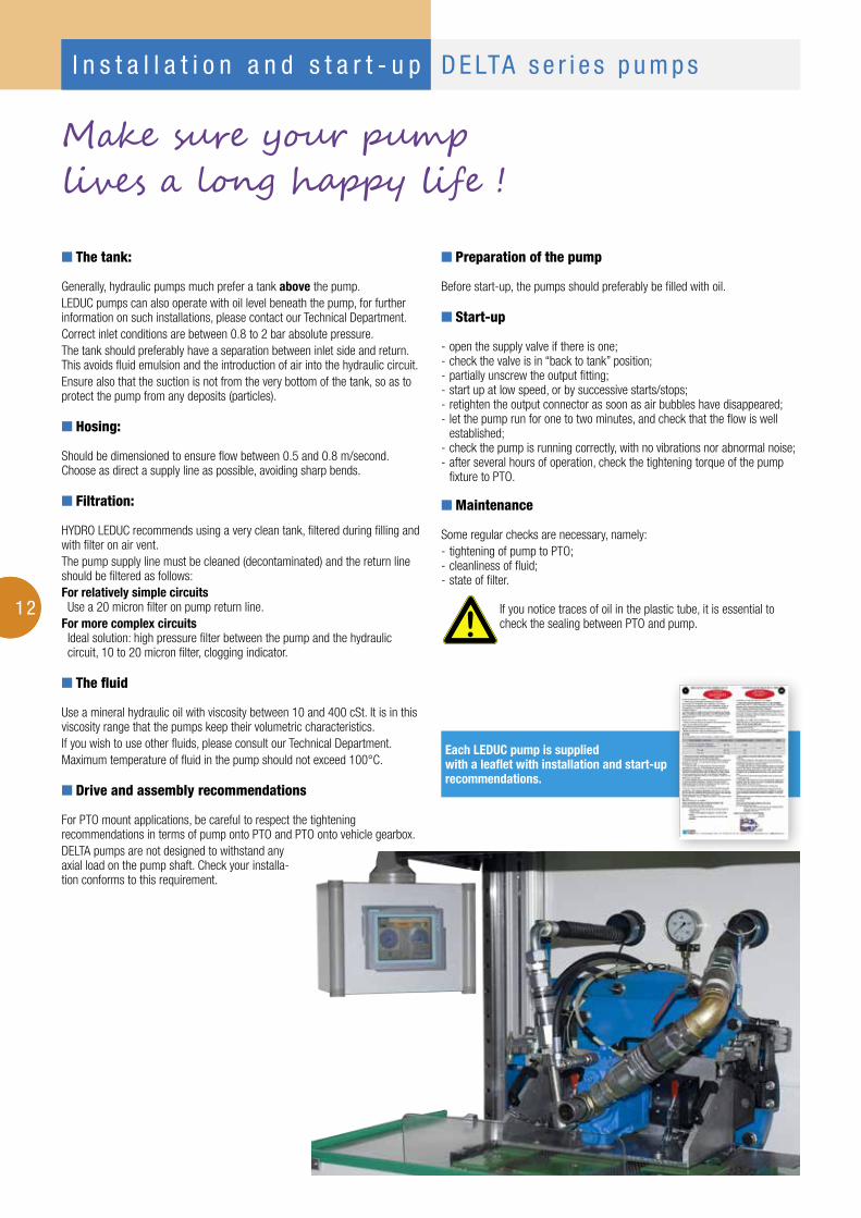
Make sure your pumplives a long happy life !
Each LEDUC pump is supplied with a leaflet with installation and start-up recommendations.
I n s t a l l a t i o n a n d s t a r t - u p D E LTA s e r i e s p u m p s

A dedicated R&D team means HYDRO LEDUC is able to adapt or create
products to meet specifi c customer requirements. Working in close
cooperation with the decision-making teams of its customers, HYDRO LEDUC optimizes
proposals based on the specifi cations submitted.
w e a r e p a s s i o n a t e a b o u t h y d r a u l i c s …
hydro-pneumatic accumulatorsBladder, diaphragm accumulators.Spherical and cylindrical accumulators.Volume capacities from 20 cc to 50 liters.Pressures up to 500 bar.Accessories for use with hydraulic accumulators.
hydraulic motors
Fixed displacement bent-axis piston motors. Models from 5 to 180 cc.Available both in ISO and SAE versions.
PAPACPAD
TXV
piston pumps for trucks
HYDRO LEDUC offers 3 types of piston pumps perfectly suited to all truck and PTO-mount applications.Fixed and variable displacement from 12 to 150 cc.
XP
Fixed displacement pumps, the W series, and variable displacement pumps, the DELTA series. High pressure capabilities within minimal size.W series: fl anges to ISO 3019/2, shafts to DIN 5480.DELTA series: SAE shafts and fl anges.
mobile and industrial pumps
micro-hydraulics This is a fi eld of exceptional HYDRO LEDUC know-how: • axial and radial piston pumps,
of fi xed and variable displacement,• axial piston micro-hydraulic motors,• micro-hydraulic units incorporating pump,
electric motors, valving, controls, etc.To users of hydraulic components which have to be housed in extremely small spaces, HYDRO LEDUC offers complete, original and reliable solutions for even the most diffi cult environments.
o t h e r p r o d u c t l i n e s
HYDRO LEDUC
SAS with capital of 4 065 000 euros
Siret 319 027 421 00019
RC Nancy B 319 027 421
a p a s s i o n f o r h y d r a u l i c s
The
info
rmat
ion
is g
iven
as
roug
h gu
ide.
Not
con
tract
ual d
ocum
ent.
Canc
els
and
repl
aces
pre
viou
s ve
rsio
n.Editech.com
m��� i� ������
HYDRO LEDUCHead office and Factory
BP 9 - F-54122 AZERAILLES (FRANCE)Tél. +33 (0)3 83 76 77 40 - Fax +33 (0)3 83 75 21 58
HYDRO LEDUC GmbHHaselwander Str. 5
D-77746 SCHUTTERWALD (GERMANY)Tel. +49 (0) 781-9482590 - Fax +49 (0) 781-9482592
HYDRO LEDUC ABGöteborgsvägen 74
SE-433 02 Sävedalen (SWEDEN)Tel. (+46) 070 26 17 770
HYDRO LEDUC N.A., Inc.19416 Park Row - Suite 170
HOUSTON, TEXAS 77084 (USA)Tel. +1 281 679 9654 - Fax +1 832 321 3553
Complete catalogues available at:www.hydroleduc.com
22/03/2013