vapor intrusion mitigation battelle 2014 - uppal 1
TRANSCRIPT

Integrated Vapor Intrusion Mitigation and Soil Vapor
Extraction Implementation for a Complex Building
Foundation
Authors: Omer J. Uppal, Matthew Ambrusch, Steven Ciambruschini,
Nadira Najib, Stewart H. Abrams, and Matthew Wenrick
Presentation Outline
Vapor Intrusion
How to Mitigate
What is SSDS?
SSDS Versus SVE
Components of a SSDS Design
SSDS Design Challenges
Case Study – Manhattan, New York
Lessons To Be Learned

Vapor Intrusion Migration of volatile chemicals from contaminated groundwater or
soil into buildings above
Indoor Air Quality
Chronic and acute health/safety hazards

How to Mitigate
Passive Venting Systems
Impermeable Membrane Liners
Sub-Slab Depressurization Systems
http://www.nj.gov/dep/srp/guidance/vaporintrusion/subsurface.htm

What is a SSDS?
Active venting system consisting of:
Fan/Blower
Well Network
Vacuum/Air Flow Rate Instrumentation
Control Panel
Telemetry System
Emission Controls

SSDS Versus SVE
Differences: Purpose
MITIGATION versus REMEDIATION
Capture versus Extraction
Similarities: Principals
Active Pneumatic Systems
Dependent on intrinsic permeability

Design Components of a SSDS Design
• Pilot Testing
• Modeling
• Design Criteria
• Air Flow Rate
• Vacuum
• ROI

SSDS Design Challenges
• Existing Structures
• Slab on grade
• Space/Access Constraints
• Heterogeneous Geology
• High Water Table

Case Study – Manhattan, New York

Site Background
Operated until June 2013 as an active dry cleaning facility
Residential dwellings located on floors two through five.
Indoor air assessment - PCE and TCE in exceedance of NYSDOH
Vapor Intrusion Guidance Matrix.

Site Constraints
2 - 6 inch thick concrete slab with granite bedrock beneath
Limited space for implementation/Manual drilling required
Possible demolition of building during application period

Pilot Testing
5 Vapor Recovery Wells (VP)
3 Shallow Vapor Probes (SVP)
Understand the site-specific sub-surface parameters (i.e., permeability)
to design the full-scale SSDS.

Outputs:
Ki, ROI, FD , PV exchanges
Benefits:
More cost-effective design
Valuable tool for SVE and VI Mitigation systems
Helps to ensure efficient and effective vapor mitigation
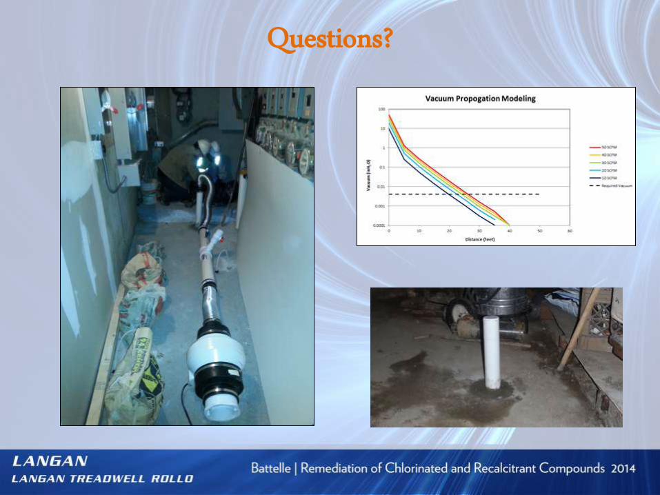
Modeling
MDFIT – Computer Pneumatic Modeling Program

Full-Scale Results
SSDS was meeting the required minimum sub-slab vacuum of
0.004 inches of water column (as recommended by USEPA)
Mitigating AND Remediating

Lessons To Be Learned
SSDS can be performed efficiently, even at complex sites, if we
understand and consider the constraints of the site when designing
the system.
Importance of pilot testing and pneumatic modeling when
designing/installing a SSDS in an existing building.
Properly designed systems can provide effective mitigation even in
a complex lithology (i.e., bedrock).
Questions?