van e ig ten tbn ¥a=z - courses.physics.illinois.edu · ee = began: o: ia = ii-is = b¥÷ lsi- ......
TRANSCRIPT

Per - phase equivalents
:Y . source + Y - load
:Ia
-
>1
Van ~
E
•
~ n ~
Ig z•n E
Ten Tbn > n
¥
Its per.
phase equivalent is given by
±¥a=zThe single phase descriptionVan ~ Ahas all information to
-
•b-
computeall 34 quantities
.
For example ,Ia= In ,
andyou can calculate
Z
Is = IIL - i2o°, IT = TIL #209 etc .

° Y . source + 1 had :
Ia a -
-
> '
I,
Van ~
Isa
-1
Ea.
Et•
~ n ~ Iz EaIb e <
-
Ten Tbn > nb
¥
Let us transform the A- had to
an equivalent Y. lad .
Tosimplify ,
Assume that Tan= vo Lo
,-
V
⇒ tab = B vo L3o°,
itIs.= But -90 : j¥€TaTea
= B vo Ll 50 :.
€t Ab
Vb

¥ =
Mfg =
beLsi,
Ea
⇐ t£÷=hzt÷tao
;Is =
EE = began:o : Ia = Ii - Is =
B¥÷ Lsi -
✓3z÷ List
Ia
Is'
>
¥,
=¥[b%L3o°- is %Lsog
= ¥, . B Vo .fs .
Lo °
=
±Eats

i. Tan = Vo Lo° drives a current
ofEa - fag,
thoughthe a- phase line
,
thatingests a
per- phase equivalent
circuit given by
+.
.¥T¥13 .
Jan~ A
•b-
Then,
the tone is theper
-
phase equivalent
of a Y . connected load with Ey = Eats i
i.e.,
q•
HintsIs EL
*¥o¥.
±III. .
•.
ZIoo . Y - A transformation .

Example # t
Consider a A- connected load with 4=345 kV,
drawing 750 mva at a pf of ons lagging .
Compute :
I Line and phase currents .
I Real § reactive powerdrawn
per phase .
I Perphase impedance .
Solution : ± |§§| = 750 MVA
⇒ BVLIL = 750 MVA
T = 750 MVA750MVA⇒ - l BT=
as uj' 256A '
T T⇒ -4
=
Is =725A.± P¢=tRe{5s¢ } c-Note the Ys in
front of Re{ Esq } .
Q¢=fIm{ 53°1 } .

NA'
t50 ° : Pg =tsRe{ 750237°} MW
¥ = } 750×0.8 MW
cost (0-8)=370. = Zoo MW .
QQ= fIm{ 7502370 } MVAR
= } 750×0.6 MVAR
= 150 MVAR .
E=fghLo=V¥Lo -451¥)↳7orin
why ?.
= 47667° R .

Iii prsiiigemainssfisonejiotineTwo 3¢ loads are connected in parallel
to
a Y . connected
lido:
°
'Funneled load 1 : 24kW at 0 's pf lagging. A - connected load 2 : 30 KVA at 0.8 pf leading
.
Find the line current phasorsII.a andIaaforthe two loads
,total
complex power I,
drawnby the loads
,and the total line
current drawn at the source . Let [Van=o.
Solution:§¢, ,=
o?4gL37° .ua. Aztywwstost
-
= 30/370 KVA .
£4,2 = 30 £370 KVA .
o : I,= §¢
, ,+ 53%2=48 kW .
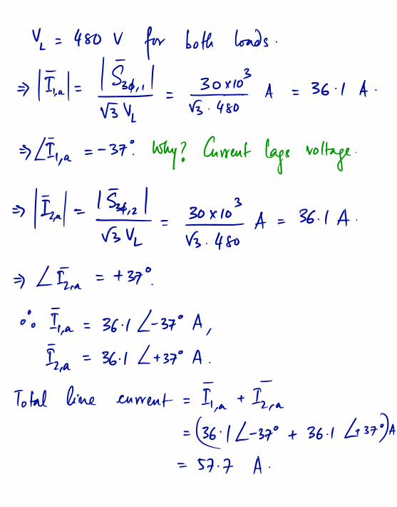
Y = 480 V for both loads .
⇒
Eat= Iffy = js÷fo± A = 36 . l A .
⇒
LIT,
a=
- 37: why ? Current lags voltage .
⇒ III.al = lr5gy÷= 30×1 A = 36.1 A .
✓3 . 4 so
⇒ L II.a
= +37 ?
° : IIa= 36.1 L - 37
°
A,
Iz, a
= 36 . l L +370 A.
Total line current = IT, a
+ II a
= 36£1 L -37° + 36.1 437DA= 57.7 A .

Example#3_
An industrialplant
consists of several
3$ induction Motors and draws 300kW
at 0.6 pf lagging .How much
per.
phasereactive
powershould be injected from a 3$ capacitor
bank in parallel to the plant toimprove
the netpower factor to og lagging .
Solution : - .^
. i- age |g§p
a = cos. '
(0-6)=53
go.no?IolQtws'
(0-9)=258,
300kW
Here, sjy and 5dg are the
complex powerswith and without the
capacitorbanks .
o : 99ft (injagftuhmnby )=3oow#ttmEjima so)
= 254.7 KVAR