vamp 300 series - esuns.com.t · pdf filenew password protected and easy to use control...
TRANSCRIPT

Protection 01
VAMP 300 SeriesModular IED > design your own protection relay
BENEFITS OF MODULAR DESIGN
1. A modular IED for different applications:VAMP300IEDfeaturesamodulardesignthatallowsuser-definedconventionalprotectionandarcflashprotectionsolutionsbothinnewandexistingpowerdistributionsystems.
2. New improved integrated arc protection: New arc option modules with either two, four or six point sensors or onefibreandfourpointsensorstogetherwithhighspeedoutputsprovidesfasteroperationtimeifanarcfaultoccurs.
3. Local push buttons for object control:Newpasswordprotectedandeasytousecontrolbuttonsforbreakercontrolling.
The VAMP 300 IED is modular and fully supervised unit that can be adapted for a wide range of applications. Free-of-charge VAMPset relay management software ensures easy commissioning, configuration and system maintenance.
The VAMP 300 series IED is based on the proven technology of VAMP protection relays and arc flash protection systems. Optional fibre or point sensor interface enable less than 2 ms operation time for arc protection.
The modularity of the VAMP 300 IED also allows a wide selection of communication protocols, including IEC 61850, Profibus DP, Modbus TCP, Modbus RTU, DNP 3.0, DeviceNet, IEC 60870-5-101, 60870-5-103, DNP TCP, IEC 60870-5-101 TCP and SPA-Bus.
Vamp - pioneer in arc flash protection

Protection VAMP 300 Series 02
Modular IED for feeder and motor protection and control
PANEL MOUNTING The conventional mounting technique has always been installing the IED on the secondary compartment's door. Limitation in this approach could be that the door construction is not strong enough for the IED's weight and suitability to wire large amount of secondary and communication cabling could be challenging.
PROJECTION MOUNTING In case the depth dimension behind the compart-ment door is limited, the IED can be equipped with frame around the collar. This arrangement reduces depth inside compartment by 45 mm.
This mounting technique allows door being lighter as the relays frame is installed in the back of the secondary compartment. Normally, the IED in this mounting principle is by the terminal blocks, hence the secondary wiring is short. Communication cabling is easier, too, as the door movement does not need to be considered. In this case, only the communication between IED base and display has to be wired.
Detachable HMI brings more flexibility
The base unit of the IED and display are connected using VAMP's VX001 cabling.
Order options provide two alternative mounting principles to VAMP 300 IED. Both options have its own advantages.
MAIN CHARACTERISTIC AND OPTIONS
• VAMP 300 F has all necessary feeder protection for industrial and utility applications for power distribution networks. Synchrochec and auto-reclosing extend automatic network control
• VAMP 300 M is designed for small and medium sized motors up-to 10 MW. External RTD module increases motor status information
• Both models have optional interface for connection of 2, 4 or 6 arc flash point sensors or 1 fibre loop and 4 arc flash point sensors
•Three alternative display options
128 x 64 LCD matrix
128 x 128 LCD matrix
128 x 128 LCD matrix (detachable)
•Power quality measurements and disturbance recorder enable capture of quick network phenomena
• Vide range of communication protocols i.e. IEC61850, Profibus DP to Modbus TCP
USER BENEFITS
• Pre-selectableamountofDI/DOoutput combinations up to i.e. 40 DI or 22 DO
• Integratedarcflashprotection• Baymimicandcontrol• Flexibleandsimpletousesolution• UserfriendlymultilingualHMI• FreeofcostVAMPSETconfiguration
and setting tool with USB connection
• Textpocketforcustomizedalarmlegend
WALL MOUNTING WITH DETACHABLE HMI
Protection VAMP 300 Series 03
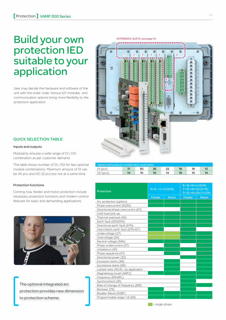
Build your own protection IED suitable to your applicationUser may decide the hardware and software of the unit with the order code. Various I/O modules and communication options bring more flexibility to the protection application.
QUICK SELECTION TABLE
Inputs and outputs
Modularity ensures a wide range of DI / DO combination as per customer demand.
The table shows number of DI / DO for few optional module combinations. Maximum amount of DI can be 40 pcs and DO 22 pcs but not at a same time.
Protection functions
Coming now, feeder and motor protection include necessary protection functions and modern control features for basic and demanding applications.
ProtectionA=3L+U+Io(5/1A)
B=3L+4U+Io(5/1A)C=3L+4U+2Io(5+1A)D=3L+4U+2Io(1+0.2A)
Feeder Motor Feeder MotorArc protection (option) Phase overcurrent (50/51) Directional phase overcurrent (67) Cold load pick-up Thermal overload (49) Earth fault (50N/51N) Directional earth fault (67N) Intermittent earth fault (67N-IEF) Undervoltage (27) Overvoltage (59) Neutral voltage (59N) Phase undercurrent (37) Unbalance (46) Phase sequence (47) Directional power (32) Excessive starts (48) Successive starts (66) Locked rotor (51LR) , by application Magnetising inrush (68F2) Frequency (81H/81L) Synchrocheck (25) Rate of change of frequency (81R) Recloser (79) Breaker failure (50BF) Programmable stage 1-8 (99)
Inputs and outputs combination examplesDI (pcs) 31 30 26 22 18 16 12DO (pcs) 14 10 10 14 18 10 14
EXTENSION SLOTS, see page 14
The optional integrated arc protection provides new dimension to protection scheme.
1 2 3 4 5 8
6
9
= single phase

Protection VAMP 300 Series 04
Control
CIRCUITBREAKER(OBJECT)CONTROL➔ THROUGH HMI
A third possibility to control circuit breakers and isolators is to use the Mimic view of the IED. User selects wanted object in the single line diagram and executes the control with dedicated Info view instructions.
CIRCUITBREAKER(OBJECT)CONTROL➔F1/F2BUTTONS
Another way to control circuit breaker or isolators is to program Function button F1 and F2 to execute the control command. Once programmed F1 could be the close and F2 open operand. A dedicated info view appears on the HMI requesting confirmation or de-selection of the action.
CIRCUITBREAKER(OBJECT)CONTROL➔ON/OFFBUTTONS
The most advanced circuit breaker controlling is to use dedicated ON / OFF control buttons for the object. Two different operational modes may be chosen:
- Selective: Once a control button is pressed a dedicated Control view with pre-determined timeout asks confirmation for the control. Possible interlocking may inhibit controlling.
- Direct: Using this mode the control of the circuit breaker is immediate. This mode is practical for instance during the commissioning stage.
Circuit breaker (object) control – through HMI
• Configuration made in “LOCAL PANEL CONFIG” setting view
"Mode for control buttons" setting determines the operational modeoftheON/OFFbutton.

Protection VAMP 300 Series 05
VAMPSET is a user-friendly, free-of-charge relay management software for setting parameters and configuring VAMP relays. Via the VAMPSET software, relay parameters, configurations and recorded data can be exchanged between PC and VAMP relays. Supporting the COMTRADE format, VAMPSET also incorporates tools for analysing relay events, waveforms and trends from data recorded by the relays, e.g. during a network fault situation.
VAMPSET Setting and Configuration Tool
Relay's setting views are organised to several folders in the VAMPSET setting tool views in order to conveniently find right data for parameterisation of the IED. The setting tool displays on-line measurements in each folder view.
The phase sequences for currents and voltages can be read on-line from the clear and explicit phasor diagram screen for easy commissioning of the relay .
Using a standard USB communication cable, the PC running VAMPSET connects to the front port of the VAMP relays. The VAMPSET software also supports TCP/IP communication via an optional port. Featuring true multi-language support the software runs on Windows environment without any need for configuration of the PC.
The VAMPSET software is future-proof, supporting future updates and new VAMP products.
Standard USB communication cable can be used.

Protection VAMP 300 Series 06
Programmable stagesThere are now eight stages available to use with various applications. Each stage can monitor any analogue (measured or calculated) signal and issue start and trip signals. Programmable stages extend the protection functionality of the manager series to a new level. For example, if four stages of frequency are not enough, with programmable stages, the maximum of 12 can be reached. Other examples are using the stages to issue an alarm when there are a lot of harmonics (THD) or indicating reverse power condition.
Programmablelogic: The logic editor has colours to enable viewing of active statuses. Further more, each input status can be also seen on-line in VAMPSET view .
Programmable stage has a possibility to compare two freely selectable signals between each other. Using this feature the user can create compare function using relay's own measured or calculated signals. One or both of the signals can be connected to comparison function over GOOSE.

Protection VAMP 300 Series 07
CommunicationVAMP is a communication expert with a wide experience in interfacing with different system integrators’ and SCADA suppliers’ RTUs, PLCs, gateways etc. using many different protocols. Flexible adaptation of the communication protocols together with powerful and easy to use software tools are the key of successful integration.
VAMP 300 IED and the VAMPSET tool provide access to practically any power system information you may need.
DeviceN
et
External I/O: M
odbus
IEC-101
IEC-103
Modbus RTU
Profibus DP
SpaBus
Ethernet IP
IEC-61850
ModBus TCP
None
DN
P 3.0
GetSet
RS-485
Profibus
Ethernet
Devive Net
Profibus
RS-232
Serial fiber
RS-485
Exte
rnal
mod
ules
COMMUNICATION MATRIX
Check which physical interface matches with certain protocols. It is possible to expand RS-232 interface with external hardware modules
NATIVE IEC 61850
The IEC 61850 protocol can be used to read or write static data or to receive events sent spontaneously from the relay. In addition, the interface allows peer-to-peer communication between the relays, called GOOSE communication. The IEC 61850 interface is confi gured with familiar, user-friendly VAMPSET software.
The IEC 61850 datamodel, data-sets, report control blocks and the GOOSE communication are configured according to the requirements of the system configuration. VAMPSET is also used to produce ICD files, which may be needed for the substation RTU configuration
The VAMP 300 IED contains native implementation, which means that the IEC 61850 functionality is embedded in the software.
Arc flash protectionVAMP relays measure fault current and with optional arc protection, also measure light via arc sensor channels, which provide monitoring for the whole switchgear. Should an arc fault occur in the switch-gear the arc protection system provides extremely fast tripping of the circuit breaker. The fault will be prevented from spreading and quickly isolated, which may save valuable assets.
Cable
CB
BB
Cable
L>(CB,BB)
L>(CB,BB)
CB CB
Cable

Protection VAMP 300 Series 08
ConnectionsVOLTAGE CONNECTION MODE
The slot 8 can accommodate four different analogue measurement cards. Model A has only one voltage input where as models B, C and D have four voltage measurement channels.
A=3L+U+Io(5/1A)
B=3L+4U+Io(5/1A)
C=3L+4U+2Io(5+1A)
D=3L+4U+2Io(1+0.2A)
Correlation between voltage measuring mode, physical voltage input and available voltages in Terminal 8/B/1 and 8/B/2. Note that terminals for voltage channel (U4) in slot 8/B/1 are 10 and 11.
Correlation between voltage measuring mode, physical voltage input and available voltages in terminal 8/C/1 (8/D/1) and 8/C/2 (8/D/2). Note that terminals for voltage channel (U4) in slot 8/C/1 (8/D/1) are 11 and 12.
The B analogue interface module
The C and D analogue interface modules
Terminal8/B/2 8/B/1
1 2 3 4 5 6 10 11
Voltage channel U1 U2 U3 U4
Mode/Usedvoltage
3LN
UL1 UL2 UL3
Not in use
3LN+U0 Uo
3LN+LLy LLy
3LN+LNy LNy
2LL+U0
U12U23
Uo
Not in use
2LL+U0+LLy LLy
2LL+U0+LNy LNy
LL+U0+LLy+LLz U12y L12z
LN+U0+LNy+LNz UL12 U11y UL1z
Terminal8/C/2and8/D/2
8/C/1and8/D/1
1 2 3 4 5 6 10 11
Voltage channel U1 U2 U3 U4
Mode/Usedvoltage
3LN
UL1 UL2 UL3
Not in use
3LN+U0 Uo
3LN+LLy LLy
3LN+LNy LNy
2LL+U0
U12U23
Uo
Not in use
2LL+U0+LLy LLy
2LL+U0+LNy LNy
LL+U0+LLy+LLz U12y L12z
LN+U0+LNy+LNz UL12 U11y UL1z

Protection VAMP 300 Series 09
Connection examples
3LN_Uo
123456789101112
IL1IL1IL2IL2IL3IL3I01I01I02I02U4U4
(S1)(S2)(S1)(S2)(S1)(S2)(S1)(S2)(S1)(S2)Uo (da)Uo (dn)
Slot 88/C1 : 1...128/D1 : 1...12
8C2 : 1...68D2 : 1...6
123456
UL1 (a)UL1 (n)UL2 (a)UL2 (n)UL3 (a)UL3 (n)
3LN_LNy
123456789101112
IL1IL1IL2IL2IL3IL3I01I01I02I02U4U4
(S1)(S2)(S1)(S2)(S1)(S2)
UL1 (a)UL1 (n)
8C2 : 1...68D2 : 1...6
123456
Slot 88/C1 : 1...128/D1 : 1...12
UL1 (a)UL1 (n)UL2 (a)UL2 (n)UL3 (a)UL3 (n)
(S1)(S2)(S1)(S2)
Voltage measuring mode: 3LN + UoVoltages measured by VTs
UL1, UL2, UL3, Uo
Values calculated UL12, UL23, UL31, U1, U2, U2/U1, f
Measurements available All
Protection functions available
All except synchrocheck
Voltage measuring mode: 3LN Voltages measured by VTs
UL1, UL2, UL3
Values calculated UL12, UL23, UL31, U1, U2, U2/U1, f, Uo
Measurements available All
Protection functions available
All except intermittent e/f and synchrocheck
Voltage measuring mode: 3LN+LNyVoltages measured by VTs
UL1, UL2, UL3, UL1y
Values calculated UL12, UL23, UL31, Uo, U1, U2, U2/U1, f
Measurements available All
Protection functions available
All except intermittent e/f and synchrocheck
Above measuring modes are typically used for feeder and motor protection schemes.
3LN connection is similar to 3LN+Uo. Open delta connection is missing in this mode but Uo is calculated.
This connection is typically used for feeder protection scheme where line-to-neutral voltage is required for synchrocheck application.

Protection VAMP 300 Series 10
V 2LL + Uo
123456
UL12UL12UL23UL23UoUo
8/C/2 : 1...68/D/2 : 1...6
UL2
UL3
UL1
(a)(b)(a)(b)(da)(dn)
V 2LL + Uo + LLy
1112
123456
UL12UL12UL23UL23UoUo
8/C/1 : 11...128/D/1 : 11...12
8/C/2 : 1...68/D/2 : 1...6
UL2
UL3
UL1
UL12UL12
(a)(b)
(a)(b)(a)(b)(da)(dn)
Voltage measuring mode: 2LL + UoVoltages measured by VTs
UL12, UL23, Uo
Values calculated UL31, UL1, UL2, UL3, U1, U2, U2/U1, f
Measurements available All
Protection functions available
All except synchrocheck
Voltage measuring mode: 2LL+Uo+LLyVoltages measured by VTs
UL12, UL23, Uo, UL12y
Values calculated UL31, UL1, UL2, UL3, U1, U2, U2/U1, f
Measurements available All
Protection functions available
All
V 3LN + LLy
1112
UL12 (a)UL12 (b)
123456
UL1 (a)UL1 (n)UL2 (a)UL2 (n)UL3 (a)UL3 (n)
8/C/1 : 11...128/D/1 : 11...12
8/C/2 : 1...68/D/2 : 1...6
UL2
UL3
UL1Voltage measuring mode: 3LN + LLyVoltages measured by VTs
UL1, UL2, UL3, UL12y
Values calculated UL12, UL23, UL31, Uo, U1, U2, U2/U1, f
Measurements available All
Protection functions available
All except intermittent e/f
Connection of voltage transformers for synchrocheck application. The other side of the CB has line-to-line connection for reference voltage.
Connection of two line-to-line and residual voltage measurement scheme.
Connection of two line-to-line and residual voltage scheme. Line-to-line reference voltage is taken from other side of the CB for synchrocheck scheme.

Protection VAMP 300 Series 11
V 2LL + Uo + LNy
1112
123456
UL12UL12UL23UL23UoUo
UL1 (a)UL1 (b)
8/C/1 : 11...128/D/1 : 11...12
8/C/2 : 1...68/D/2 : 1...6
UL2
UL3
UL1
(a)(b)(a)(b)(da)(dn)
V LL + Uo + LLy + LLz
1112
123456
UL12UL12UL12UL12UoUo
UL12 (a)UL12 (b)
8/C/1 : 11...128/D/1 : 11...12
8/C/2 : 1...68/D/2 : 1...6
UL2
UL3
UL1
(a)(b)(a)(b)(da)(dn)
V NL + Uo + LNy + LNz
1112
8/C/1 : 11...128/D/1 : 11...12
123456
UL1UL1UL1UL1UoUo
8/C/2 : 1...68/D/2 : 1...6
UL1 (a)UL1 (n)
UL2
UL3
UL1
(a)(n)(a)(n)(da)(dn)
Voltage measuring mode: 2LL+Uo+LNyVoltages measured by VTs
UL12, UL23, Uo, UL1y
Values calculated UL31, UL1, UL2, UL3, U1, U2, U2/U1, f
Measurements available All
Protection functions available
All
Voltagemeasuringmode:LL+Uo+LLy+LLzVoltages measured by VTs
UL12, Uo, UL12y, UL12z
Values calculated UL1, UL2, UL3, f
Measurements available
Protection functions available
Single phase voltage protection
Voltagemeasuringmode:LN+Uo+LNy+LNzVoltages measured by VTs
UL1, Uo, UL1y, UL1z
Values calculated UL12, UL23, UL31, f
Measurements available
Protection functions available
Single phase voltage protection
Connection of two line-to-line and residual voltage scheme. The other side of the CB has phase-to-neutral connection for synchrocheck.
This scheme has two CBs to be synchronized. Left side of the bus bar has line-to-line and right side line-to-line connection for synchrocheck's reference voltages. In the middle system voltages are measured by phase-to-neutral and open delta connection.
This scheme has two CBs to be synchronized. Left and right sides of the bus bar have line-to-neutral connections for synchrocheck's reference voltages. In the middle system voltages are measured by phase-to-neutral and open delta connection.

Protection VAMP 300 Series 12
Dimensional drawings
T max. 1.2N•m10.6 lb-in
T max. 0.5-0.6N•m4.4-5.3 lb-in
2.5N•m22 lb-in
3N•m27 lb-in
VAMP 300 PANEL MOUNTING
ON
F1
F2
OK
OI
ON
F1
F2
OK
OI
ON
F1
F2
OK
OI
ON
OK
Vamp 300
F1 F2OI
27010.63
1766.93
mmin
T max. 1.2N•m10.6 lb-in
T max. 0.5-0.6N•m4.4-5.3 lb-in
2.5N•m22 lb-in
3N•m27 lb-in
VAMP 300 PANEL MOUNTING
ON
F1
F2
OK
OI
ON
F1
F2
OK
OI
ON
F1
F2
OK
OI
ON
OK
Vamp 300
F1 F2OI
27010.63
1766.93
mmin
T max. 1.2N•m10.6 lb-in
T max. 0.5-0.6N•m4.4-5.3 lb-in
2.5N•m22 lb-in
3N•m27 lb-in
VAMP 300 PANEL MOUNTING
ON
F1
F2
OK
OI
ON
F1
F2
OK
OI
ON
F1
F2
OK
OI
ON
OK
Vamp 300
F1 F2OI
27010.63
1766.93
mmin
PANEL MOUNTING
M4x20Torx T-20
1.5Nm
2
1
mmin
Panel mounting VAMP 300 systemwith detachable display
2014-5-21Grafimer / K. Kimpimäki
3
ON
OK
Vamp 300
F1 F2OI
27010.63
261.02
mmin
1766.93
ON
F1
F2
OK
Vamp 300
OI
ON
F1
F2
OK
Vamp 300
OI
2108.27
1003.94
50.2
200.79
11.50.45
Ø
1807.09
Ø 70.28
190.75
1997.83
1807.09
1807.09
2479.72
180.71
341.34
min. 2.5mm2
Ø 5-8mm
Nut M5 1.5Nm
T max. 1.2Nm10.6 lb.in
T max. 0.5...0.6Nm4.4...5.3 lb.in
1807.09
1987.80
150 5.91
WALL MOUNTING WITH DETACHABLE HMI
M4x20Torx T-20
1.5Nm
2
1
mmin
Panel mounting VAMP 300 systemwith detachable display
2014-5-21Grafimer / K. Kimpimäki
3
ON
OK
Vamp 300
F1 F2OI
27010.63
261.02
mmin
1766.93
ON
F1
F2
OK
Vamp 300
OI
ON
F1
F2
OK
Vamp 300
OI
2108.27
1003.94
50.2
200.79
11.50.45
Ø
1807.09
Ø 70.28
190.75
1997.83
1807.09
1807.09
2479.72
180.71
341.34
min. 2.5mm2
Ø 5-8mm
Nut M5 1.5Nm
T max. 1.2Nm10.6 lb.in
T max. 0.5...0.6Nm4.4...5.3 lb.in
1807.09
1987.80
150 5.91
PROJECTION MOUNTING 2
Vamp 300
ON
F1
F2
OK
OI
3b
1.0-600.04-2.36
225 8.86
152 5.98
1
4
2.5N•m22 lb-in
3c
3N•m27 lb-in
mmin
mmin
T max. 1.2N•m10.6 lb-in
T max. 0.5-0.6N•m4.4-5.3 lb-in
VAMP 300 PROJECTION MOUNTING
3
3a
3a
CLICK !
ON
F1
F2
OK
Vamp 300
OI
Vamp 300
150 5.91
2309.05183
7.20 45
1.771385.43
ON
OK
Vamp 300
F1 F2OI
27010.63
1766.93
*
*
Projection for 300 series
152 5.98
172 6.77
269 10.59
224 8.82
ON
F1
F2
OK
OI
2
Vamp 300
ON
F1
F2
OK
OI
3b
1.0-600.04-2.36
225 8.86
152 5.98
1
4
2.5N•m22 lb-in
3c
3N•m27 lb-in
mmin
mmin
T max. 1.2N•m10.6 lb-in
T max. 0.5-0.6N•m4.4-5.3 lb-in
VAMP 300 PROJECTION MOUNTING
3
3a
3a
CLICK !
ON
F1
F2
OK
Vamp 300
OI
Vamp 300
150 5.91
2309.05183
7.20 45
1.771385.43
ON
OK
Vamp 300
F1 F2OI
27010.63
1766.93
*
*
Projection for 300 series
152 5.98
172 6.77
269 10.59
224 8.82
ON
F1
F2
OK
OI
2
ON
F1
F2
OK
Vamp 300
OI
3b
ON
OK
Vamp 300
F1 F2OI
1.0-600.04-2.36
225 8.86
152 5.98
1
4
27010.63
150 5.91
2309.05183
7.20
2.5Nm22 lb.in
3c
3Nm27 lb.in
mmin
mmin
T max. 1.2Nm10.6 lb.in
T max. 0.5...0.6Nm4.4...5.3 lb.in
ON
F1
F2
OK
Vamp 300
OI
269 10.59
152 5.98
172 6.77
224 8.82
45 1.77
3
3a
3a
CLICK !
1766.93
ON
F1
F2
OK
Vamp 300
OI
1375.39
ON
F1
F2
OK
Vamp 321
vamp
ON
F1
F2
OK
Vamp 321
vamp
ON
F1
F2
OK
Vamp 321
vamp
ON
OK
Vamp 321
F1 F2
vamp

Protection VAMP 300 Series 13
Disturbance tests Standard&Testclass/levelTestvalueEmission- Conducted - Emitted
EN 61000-6-4 / IEC 60255-26EN 55011, Class A / IEC 60255-25 EN 55011, Class A / IEC 60255-25 / CISPR 11
0.15 – 30 MHz30 – 1 000 MHz
Immunity- 1Mhz damped oscillatory wave- Static discharge (ESD) - Emitted HF field- Fast transients (EFT)- Surge
- Conducted HF field- Power-frequency magnetic field- Pulse magnetic field- Voltage interruptions- Voltage alternative component- Voltage dips and short interruptions
EN 61000-6-2 / IEC 60255-26IEC 60255-22-1EN 61000-4-2 Level 4 / IEC 60255-22-2 Class 4 EN 61000-4-3 Level 3 / IEC 60255-22-3EN 61000-4-4 Level 4 / IEC 60255-22-4 Class AEN 61000-4-5 Level 4 / IEC 60255-22-5
EN 61000-4-6 Level 3 / IEC 60255-22-6EN 61000-4-8EN 61000-4-9 Level 5EN 61000-4-29 / IEC 60255-11EN 61000-4-17 / IEC 60255-11EN 61000-4-11
± 2.5 kVp CM, ± 2.5 kVp DM± 8 kV contact, ± 15 kV air 80 - 2700 MHz, 10 V/m± 4 kV 5/50 ns, 5 kHz± 4 kV, 1.2/50 µs, CM2 kV, 1.2/50 µs, DM0.15 - 80 MHz, 10 Vemf300 A/m (continuous), 1000 A / m 1 – 3 s1000 A/m, 1.2 / 50 µs30 % / 1 s, 60 % / 0.1 s, 100 % / 0.05 s12 % of operating voltage (DC) / 10 min30 % / 10 ms, 100 % / 10 ms, 60 %/100 ms, >95 % / 5000 ms
Electrical safety tests- Impulse voltage withstand- Dielectric test- Insulation resistance- Protective bonding resistance- Power supply burden
EN 60255-5, Class IIIEN 60255-5, Class IIIEN 60255-5EN 60255-27IEC 60255-1
5 kV, 1.2/50 µs2 kV, 50 Hz
Mechanical testsDevice in operation- Vibrations- ShocksDevicede-energized- Vibrations- Shocks- Bump
IEC 60255-21-1, Class II / IEC 60068-2-6, FcIEC 60255-21-2, Class II / IEC 60068-2-27, Ea
IEC 60255-21-1, Class II / IEC 60068-2-6, FcIEC 60255-21-2, Class II / IEC 60068-2-27, EaIEC 60255-21-2, Class II / IEC 60068-2-27, Ea
1Gn, 10Hz – 150 HZ10Gn / 11 ms
2Gn, 10 Hz – 150 HZ30Gn / 11 ms20 Gn / 16 ms
Environmental testsDevice in operation- Dry heat- Cold- Damp heat, cyclic- Damp heat, staticDevice in storage- Dry heat- Cold
EN / IEC 60068-2-2, Bd EN / IEC 60068-2-1, AdEN / IEC 60068-2-30, DbEN / IEC 60068-2-78, Cab
EN / IEC 60068-2-2, BbEN / IEC 60068-2-1, Ab
+70°C- 40°CFrom +25°C to +55°C, From 93% RH to 98% RH, 6 days+40°C, 93% RH, 10 days
+70°C- 40°C
Environmental conditionsAmbient temperature, in-service Ambient temperature, storage Relative humidityMaximum operating altitude Degreeofprotection(IEC60529)WeightDimension(WxHxD)
-25 – +60°C -40 – +70 °C < 95%, no condensation allowed 2000 m IP54 (from front when panel mounted) 3.2 kg or higher (depends of options) 270 x 176 x 230 mm
PackageDimensions(WxHxD)Weight(IED,PackageandManual)
270 x 176 x 230 mm 4.2 kg or higher (depends of options)
Tests and environmental

Protection VAMP 300 Series 14
Application F = Feeder (Slot 8: HW = A, B, C or D) VAMP 300 feeder IEDM = Motor (Slot 8: HW = A, B, C or D) VAMP 300 motor IEDSupply voltage [V] C = Power C 110 - 240 (80 .. 265 Vac/dc, 5 x DO heavy duty, A1, SF)D = Power D 24 - 48 (18 .. 60Vdc, 5 x DO heavy duty, A1, SF)I/OCardI A = None B = 3BIO+2Arc (3 x BI/BO, 2 x Arc sensor, T2, T3, T4) C = F2BIO+1Arc (Fibre 2 x BI/BO, 1 x Arc loop sensor, T2, T3, T4)G = 6DI+4DO (6 x DI, 4 x DO) I = 10DI (10 x DI)I/OCardII A = None G = 6DI+4DO (6 x DI, 4 x DO) I = 10DI (10 x DI) I/OCardIII A = None G = 6DI+4DO (6 x DI, 4 x DO) I = 10DI (10 x DI) I/OCardIV A = None D = 2IGBT (2 x IGBT High speed outputs) G = 6DI+4DO (6 x DI, 4 x DO) I = 10DI (10 x DI) Option card I A = None D = 4Arc (4 x Arc sensor)P = PP (Plastic / Plastic serial fibre)R = GG (Glass / Glass serial fibre)Future option A = None Analogmeasurementcard(Seeapplication)A = 3L+U+Io (5/1 A) B = 3L+4U+Io (5/1 A) C = 3L+4U+2Io (5+1 A)D = 3L+4U+2Io (1+0.2 A)Communication interface I A = None B = RS232 C = RS232+RJ (RS232 + Ethernet RJ-45 100 Mbs)D = RS232+LC (RS232 + Ethernet LC 100 Mbs)N = 2 x RJ-45 100Mbs ethernet interface O = 2 x LC 100Mbps ethernet fibre interface
Future option A = None Display typeA = 128 x 64 LCD matrixB = 128 x 128 (128 x 128 LCD matrix) C = 128 x 128Ext (128 x 128 LCD matrix, detachable, 2 m cable) (1
DI treshold voltage1 = 24 VDC / 110 VAC2 = 110 VDC / 220 VAC3 = 220 VDC
V300- - - A A -
SLOT NUMBERS, see page 3
1 2 3 4 5 6 7 8 9 10
Order Codes
C = RS232+RJ (RS232 + Ethernet RJ-45 100 Mbs)
B = 3BIO+2Arc (3 x BI/BO, 2 x Arc sensor, T2, T3, T4)
G = 6DI+4DO (6 x DI, 4 x DO)
D = RS232+LC (RS232 + Ethernet LC 100 Mbs)
Note: (1 Cable type: VX001-x, where x = 1, 2 or 3 meters. Default length is 2 meters.

Protection VAMP 300 Series 15
ACCESSORIES Order code Description NoteVX052-3 USB programming cable (Vampset) Cable length 3 mVX067 VAMP 300/321 split cable for COM1-2 and COM 3-4 ports Cable length 3 m
VSE001PP Fiber optic Interface Module (plastic - plastic) Max. distance 1 kmVSE001GG Fiber optic Interface Module (glass - glass) Max. distance 1 kmVSE001GP Fiber optic Interface Module (glass - plastic) Max. distance 1 kmVSE001PG Fiber optic Interface Module (plastic - glass) Max. distance 1 kmVSE002 RS485 ModuleVSE009 DeviceNet module
VPA3CG Profibus DP fieldbus option boardVX072 VAMP 300/321 profibus cable Cable length 3m
3P014 MOXA TCF-90 Max. distance 40 kmVX048 RS232 converter cable for MOXA TCF-90 Cable length 3 m3P022 MOXA TCF-142-S-ST Max. distance 40 kmVX062 RS232 converter cable for MOXA TCF-142-S-ST Cable length 3 m
VA 1 DA-6 Arc Sensor Cable length 6 mVA 1 DA-20 Arc Sensor Cable length 20 mVA 1 DA-6s Arc Sensor, shielded Cable length 6 mVA 1 DA-20s Arc Sensor, shielded Cable length 20 mVA 1 EH-6 Arc Sensor (Pipe type) Cable length 6 mVA 1 EH-20 Arc Sensor (Pipe type) Cable length 20 mARC SLm-x Fibre sensor, 8 000 lx x = fibre lenght (1
VIO 12 AB RTD Module, 12pcs RTD inputs, RS 485 Communication (24-230 Vac/dc)
VIO 12 AC RTD/mA Module, 12pcs RTD inputs, PTC, mA inputs/outputs, RS232, RS485 and Optical Tx/Rx Communication (24 Vdc)
VIO 12 AD RTD/mA Module, 12pcs RTD inputs, PTC, mA inputs/outputs, RS232, RS485 and Optical Tx/Rx Communication (48-230 Vac/dc)
VYX695 Projection for 300-serie Height 45 mm
Note 1. Fibre lengths 1, 5, 10, 15, 20, 25, 30, 35, 40, 50, 60 or 70 m
Protection VAMP 300 Series 16
10-2014
As standards, specifications and designs change from time to time, please ask for confirmation of the information given in this publication.
Design: Schneider Electric Industries SAS - WILMAPhotos: Schneider Electric Industries SAS This document has been
printed on recycled paper.
35, rue Joseph Monier CS 30323 F - 92506 Rueil Malmaison Cedex (France)Tel.: +33 (0) 1 41 29 70 00RCS Nanterre 954 503 439 Capital social 896 313 776 €www.schneider-electric.com/energy-automation
DEVICE TRACK RECORD
•SchneiderElectric’sVAMPRange specialises in protection protection relays,arcflashprotectionandmeasuring andmonitoringunitsforpowersystems.
•VAMP’smedium-voltageandsub- transmissionprotectionrelaysareusedin numerous applications, from overhead linefeedersandsubstationstopower plantsandindustrialpowersystem. Theiruniqueintegratedarcflashfault protectionfunctionalityenhancesthe safetyofbothpeopleandpropertyand has made VAMP a leading manufacturer inarcflashprotectionworldwide.All VAMP products meet the latest internationalstandardsandregulations.
© 2
014
Sch
neid
er E
lect
ric In
dust
ries
SA
S -
All
right
s re
serv
ed
NRJED113425EN
Schneider Electric Industries SAS