valvemate 7160ra radial valve controller/media/files/nordson/efd/...electronic pdf les of nordson...
TRANSCRIPT

ValveMate 7160RA Radial Valve ControllerOperating Manual
™
Electronic pdf files of Nordson EFD manuals are also available at www.nordsonefd.com

ValveMate 7160RA Radial Valve Controller
2 www.nordsonefd.com [email protected] 800-556-3484 Sales and service of Nordson EFD dispensing systems are available worldwide.
You have selected a reliable, high-quality dispensing system from Nordson EFD, the world leader in fluid dispensing. The ValveMate™ 7160RA controller was designed specifically for industrial dispensing and will provide you with years of trouble-free, productive service.
This manual will help you maximize the usefulness of your ValveMate 7160RA controller.
Please spend a few minutes to become familiar with the controls and features. Follow our recommended testing procedures. Review the helpful information we have included, which is based on more than 50 years of industrial dispensing experience.
Most questions you will have are answered in this manual. However, if you need assistance, please do not hesitate to contact EFD or your authorized EFD distributor. Detailed contact information is provided on the last page of this document.
The Nordson EFD Pledge
Thank You!
You have just purchased the world’s finest precision dispensing equipment.
I want you to know that all of us at Nordson EFD value your business and will do everything in our power to make you a satisfied customer.
If at any time you are not fully satisfied with our equipment or the support provided by your Nordson EFD Product Application Specialist, please contact me personally at 800.556.3484 (US), 401.431.7000 (outside US), or [email protected].
I guarantee that we will resolve any problems to your satisfaction.
Thanks again for choosing Nordson EFD.
Srini Subramanian, General ManagerSrini Subramanian

ValveMate 7160RA Radial Valve Controller
3www.nordsonefd.com [email protected] 800-556-3484 Sales and service of Nordson EFD dispensing systems are available worldwide.
Contents ..........................................................................................................................................................................3Introduction .....................................................................................................................................................................4Nordson EFD Product Safety Statement ........................................................................................................................5
Halogenated Hydrocarbon Solvent Hazards ...............................................................................................................6High Pressure Fluids ....................................................................................................................................................6Qualified Personnel ......................................................................................................................................................6Intended Use ...............................................................................................................................................................7Regulations and Approvals ..........................................................................................................................................7Personal Safety ............................................................................................................................................................7Fire Safety ....................................................................................................................................................................8Preventive Maintenance ..............................................................................................................................................8Important Disposable Component Safety Information ................................................................................................9Action in the Event of a Malfunction ............................................................................................................................9Disposal .......................................................................................................................................................................9
Specifications ................................................................................................................................................................10Front Panel Buttons / Modes of Operation ...................................................................................................................11Indicator Lamps ............................................................................................................................................................11How To ..........................................................................................................................................................................12
How to Make On-the-Fly (OTF) Time Adjustments in the RUN Mode .......................................................................12How to Set the MOTOR Control Mode ......................................................................................................................12How to Use the TEACH Mode ...................................................................................................................................12How to Purge with or without Nozzle Air ...................................................................................................................12How to Adjust the Nozzle Air Delay / Radial Motor Delay .........................................................................................13How to Enable / Disable the Steady / Timer Override Function ................................................................................13How to Enable / Disable the Low Air Pressure Alarm ................................................................................................13How to Select BAR or PSI Pressure Readout ...........................................................................................................13How to Enable / Disable CC INIT I/O as an External Alarm Input .............................................................................14
Typical Setup ................................................................................................................................................................15Mounting the ValveMate 7160RA ..................................................................................................................................16External Power Adapter ................................................................................................................................................17Back Panel Markings .....................................................................................................................................................17Input / Output Connection ............................................................................................................................................18
Initiate Connections ...................................................................................................................................................19Alarm OUT Connection ..............................................................................................................................................19Alarm IN Connection ..................................................................................................................................................19End-of-Cycle (EOC) Connection ................................................................................................................................1924 VDC Output ..........................................................................................................................................................19
I/O Connection Schematics ..........................................................................................................................................20Air Connections .............................................................................................................................................................21
Air Input Connection ..................................................................................................................................................21Air Output Connections .............................................................................................................................................21
Air Motor Lubrication Setup ..........................................................................................................................................22Radial Spinner Valve Setup ...........................................................................................................................................23Final Setup Checklist — Radial Spinner Valve ..............................................................................................................25Radial Spray Valve Setup ..............................................................................................................................................26Final Setup Checklist — Radial Spray Valve .................................................................................................................27Replacement Parts ........................................................................................................................................................28Troubleshooting .............................................................................................................................................................29
Contents

ValveMate 7160RA Radial Valve Controller
4 www.nordsonefd.com [email protected] 800-556-3484 Sales and service of Nordson EFD dispensing systems are available worldwide.
IntroductionNOTE: The primary control of deposit size is the valve open time. The ValveMate 7160RA provides easy access and “on the fly” adjustment of valve open time.
The ValveMate 7160RA is an EFD radial valve controller, incorporating programmable dispense time, digital time readout, and input / output communication with host machine PLCs.
Other features include:
• Push-button time setting or one touch time programming.
• Floating decimal, providing dispense time ranges of 0.001 to 99.9 seconds.
• Bright red LED display.
• Push-button purge feature.
• Low air-pressure, optional tank low level detection, or other alarm detection devices.
• End-of-cycle (EOC) feedback signal.
The ValveMate 7160RA has been designed with the machine builder and operator in mind. The objectives are to bring valve control close to the point of application and to provide the features necessary to make setup and operation as easy and precise as possible.
The ValveMate 7160RA is easy to operate. Once you have reviewed the features, you will understand the benefits and the ease of control the ValveMate 7160RA provides.
As with all EFD products, the ValveMate 7160RA has been produced to exacting specifications and thoroughly tested prior to shipment.
To obtain maximum performance from this equipment, please read the instructions carefully.
SafetyPlease read the EFD product safety statement included with this operating manual. Follow all appropriate safety instructions.

ValveMate 7160RA Radial Valve Controller
5www.nordsonefd.com [email protected] 800-556-3484 Sales and service of Nordson EFD dispensing systems are available worldwide.
Nordson EFD Product Safety Statement
The safety messages that follow have a CAUTION level hazard. Failure to comply may result in minor or moderate injury.
CAUTION
READ MANUALRead manual for proper use of this equipment. Follow all safety instructions. Task- and equipment-specific warnings, cautions, and instructions are included in equipment documentation where appropriate. Make sure these instructions and all other equipment documents are accessible to persons operating or servicing equipment.
The safety message that follows has a WARNING level hazard. Failure to comply could result in death or serious injury.
WARNING
ELECTRIC SHOCKRisk of electric shock. Disconnect power before removing covers and / or disconnect, lock out, and tag switches before servicing electrical equipment. If you receive even a slight electrical shock, shut down all equipment immediately. Do not restart the equipment until the problem has been identified and corrected.
MAXIMUM AIR PRESSUREUnless otherwise noted in the product manual, the maximum air input pressure is 7.0 bar (100 psi). Excessive air input pressure may damage the equipment. Air input pressure is intended to be applied through an external air pressure regulator rated for 0 to 7.0 bar (0 to 100 psi).
RELEASE PRESSURERelease hydraulic and pneumatic pressure before opening, adjusting, or servicing pressurized systems or components.
BURNSHot surfaces! Avoid contact with the hot metal surfaces of heated components. If contact can not be avoided, wear heat-protective gloves and clothing when working around heated equipment. Failure to avoid contact with hot metal surfaces can result in personal injury.

ValveMate 7160RA Radial Valve Controller
6 www.nordsonefd.com [email protected] 800-556-3484 Sales and service of Nordson EFD dispensing systems are available worldwide.
Nordson EFD Product Safety Statement (continued)
Halogenated Hydrocarbon Solvent HazardsDo not use halogenated hydrocarbon solvents in a pressurized system that contains aluminum components. Under pressure, these solvents can react with aluminum and explode, causing injury, death, or property damage. Halogenated hydrocarbon solvents contain one or more of the following elements.
Element Symbol Prefix
Fluorine F “Fluoro-” Chlorine Cl “Chloro-” Bromine Br “Bromo-” Iodine I “Iodo-”
Check the Safety Data Sheet (SDS) or contact your material supplier for more information. If you must use halogenated hydrocarbon solvents, contact your EFD representative for compatible EFD components.
High Pressure FluidsHigh pressure fluids, unless they are safely contained, are extremely hazardous. Always release fluid pressure before adjusting or servicing high pressure equipment. A jet of high pressure fluid can cut like a knife and cause serious bodily injury, amputation, or death. Fluids penetrating the skin can also cause toxic poisoning.
WARNINGAny injury caused by high pressure liquid can be serious. If you are injured or even suspect an injury:
• Go to an emergency room immediately. • Tell the doctor that you suspect an injection injury.• Show the doctor the following note.• Tell the doctor what kind of material you were dispensing.
Medical Alert — Airless Spray Wounds: Note to PhysicianInjection in the skin is a serious traumatic injury. It is important to treat the injury surgically as soon as possible. Do not delay treatment to research toxicity. Toxicity is a concern with some exotic coatings injected directly into the bloodstream.
Qualified PersonnelEquipment owners are responsible for making sure that EFD equipment is installed, operated, and serviced by qualified personnel. Qualified personnel are those employees or contractors who are trained to safely perform their assigned tasks. They are familiar with all relevant safety rules and regulations and are physically capable of performing their assigned tasks.

ValveMate 7160RA Radial Valve Controller
7www.nordsonefd.com [email protected] 800-556-3484 Sales and service of Nordson EFD dispensing systems are available worldwide.
Nordson EFD Product Safety Statement (continued)
Intended UseUse of EFD equipment in ways other than those described in the documentation supplied with the equipment may result in injury to persons or damage to property. Some examples of unintended use of equipment include:
• Using incompatible materials.• Making unauthorized modifications.• Removing or bypassing safety guards or interlocks.• Using incompatible or damaged parts.• Using unapproved auxiliary equipment.• Operating equipment in excess of maximum ratings.• Operating equipment in an explosive atmosphere.
Regulations and ApprovalsMake sure all equipment is rated and approved for the environment in which it is used. Any approvals obtained for Nordson EFD equipment will be voided if instructions for installation, operation, and service are not followed. If the equipment is used in a manner not specified by Nordson EFD, the protection provided by the equipment may be impaired.
Personal SafetyTo prevent injury, follow these instructions:
• Do not operate or service equipment unless you are qualified.
• Do not operate equipment unless safety guards, doors, and covers are intact and automatic interlocks are operating properly. Do not bypass or disarm any safety devices.
• Keep clear of moving equipment. Before adjusting or servicing moving equipment, shut off the power supply and wait until the equipment comes to a complete stop. Lock out power and secure the equipment to prevent unexpected movement.
• Make sure spray areas and other work areas are adequately ventilated.
• When using a syringe barrel, always keep the dispensing end of the tip pointing towards the work and away from the body or face. Store syringe barrels with the tip pointing down when they are not in use.
• Obtain and read the Safety Data Sheet (SDS) for all materials used. Follow the manufacturer’s instructions for safe handling and use of materials and use recommended personal protection devices.
• Be aware of less-obvious dangers in the workplace that often cannot be completely eliminated, such as hot surfaces, sharp edges, energized electrical circuits, and moving parts that cannot be enclosed or otherwise guarded for practical reasons.
• Know where emergency stop buttons, shutoff valves, and fire extinguishers are located.
• Wear hearing protection to protect against hearing loss that can be caused by exposure to vacuum exhaust port noise over long periods of time.

ValveMate 7160RA Radial Valve Controller
8 www.nordsonefd.com [email protected] 800-556-3484 Sales and service of Nordson EFD dispensing systems are available worldwide.
Nordson EFD Product Safety Statement (continued)
Fire SafetyTo prevent a fire or explosion, follow these instructions:
• Shut down all equipment immediately if you notice static sparking or arcing. Do not restart the equipment until the cause has been identified and corrected.
• Do not smoke, weld, grind, or use open flames where flammable materials are being used or stored.
• Do not heat materials to temperatures above those recommended by the manufacturer. Make sure heat monitoring and limiting devices are working properly.
• Provide adequate ventilation to prevent dangerous concentrations of volatile particles or vapors. Refer to local codes or the SDS for guidance.
• Do not disconnect live electrical circuits when working with flammable materials. Shut off power at a disconnect switch first to prevent sparking.
• Know where emergency stop buttons, shutoff valves, and fire extinguishers are located.
Preventive MaintenanceAs part of maintaining continuous trouble-free use of this product, Nordson EFD recommends the following simple preventive maintenance checks:
• Periodically inspect tube-to-fitting connections for proper fit. Secure as necessary.
• Check tubing for cracks and contamination. Replace tubing as necessary.
• Check all wiring connections for looseness. Tighten as necessary.
• Clean: If a front panel requires cleaning, use a clean, soft, damp rag with a mild detergent cleaner. DO NOT USE strong solvents (MEK, acetone, THF, etc.) as they will damage the front panel material.
• Maintain: Use only a clean, dry air supply to the unit. The equipment does not require any other regular maintenance.
• Test: Verify the operation of features and the performance of equipment using the appropriate sections of this manual. Return faulty or defective units to Nordson EFD for replacement.
• Use only replacement parts that are designed for use with the original equipment. Contact your Nordson EFD representative for information and advice.

ValveMate 7160RA Radial Valve Controller
9www.nordsonefd.com [email protected] 800-556-3484 Sales and service of Nordson EFD dispensing systems are available worldwide.
Important Disposable Component Safety InformationAll Nordson EFD disposable components, including syringe barrels, cartridges, pistons, tip caps, end caps, and dispense tips, are precision engineered for one-time use. Attempting to clean and re-use components will compromise dispensing accuracy and may increase the risk of personal injury.
Always wear appropriate protective equipment and clothing suitable for your dispensing application and adhere to the following guidelines:
• Do not heat syringe barrels or cartridges to a temperature greater than 38° C (100° F).• Dispose of components according to local regulations after one-time use.• Do not clean components with strong solvents (MEK, acetone, THF, etc.).• Clean cartridge retainer systems and barrel loaders with mild detergents only.• To prevent fluid waste, use Nordson EFD SmoothFlow™ pistons.
Action in the Event of a MalfunctionIf a system or any equipment in a system malfunctions, shut off the system immediately and perform the following steps:
1. Disconnect and lock out system electrical power. If using hydraulic and pneumatic shutoff valves, close and relieve pressure.
2. For Nordson EFD air-powered dispensers, remove the syringe barrel from the adapter assembly. For Nordson EFD electro-mechanical dispensers, slowly unscrew the barrel retainer and remove the barrel from the actuator.
3. Identify the reason for the malfunction and correct it before restarting the system.
DisposalDispose of equipment and materials used in operation and servicing according to local codes.
Nordson EFD Product Safety Statement (continued)
ValveMate 7160RA Radial Valve Controller
10 www.nordsonefd.com [email protected] 800-556-3484 Sales and service of Nordson EFD dispensing systems are available worldwide.
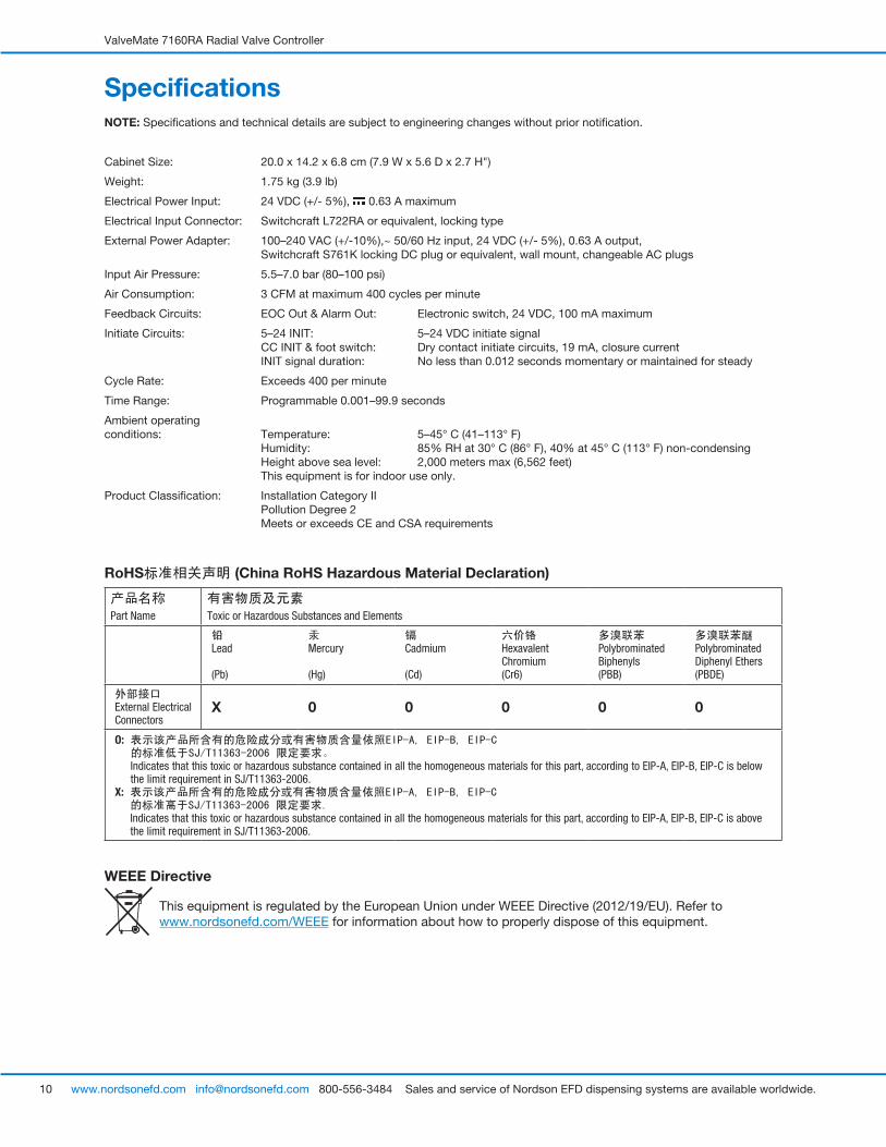
SpecificationsNOTE: Specifications and technical details are subject to engineering changes without prior notification.
Cabinet Size: 20.0 x 14.2 x 6.8 cm (7.9 W x 5.6 D x 2.7 H")
Weight: 1.75 kg (3.9 lb)
Electrical Power Input: 24 VDC (+/- 5%), 0.63 A maximum
Electrical Input Connector: Switchcraft L722RA or equivalent, locking type
External Power Adapter: 100–240 VAC (+/-10%),~ 50/60 Hz input, 24 VDC (+/- 5%), 0.63 A output, Switchcraft S761K locking DC plug or equivalent, wall mount, changeable AC plugs
Input Air Pressure: 5.5–7.0 bar (80–100 psi)
Air Consumption: 3 CFM at maximum 400 cycles per minute
Feedback Circuits: EOC Out & Alarm Out: Electronic switch, 24 VDC, 100 mA maximum
Initiate Circuits: 5–24 INIT: 5–24 VDC initiate signal CC INIT & foot switch: Dry contact initiate circuits, 19 mA, closure current INIT signal duration: No less than 0.012 seconds momentary or maintained for steady
Cycle Rate: Exceeds 400 per minute
Time Range: Programmable 0.001–99.9 seconds
Ambient operating conditions: Temperature: 5–45° C (41–113° F)
Humidity: 85% RH at 30° C (86° F), 40% at 45° C (113° F) non-condensing Height above sea level: 2,000 meters max (6,562 feet) This equipment is for indoor use only.
Product Classification: Installation Category II Pollution Degree 2 Meets or exceeds CE and CSA requirements
RoHS标准相关声明 (China RoHS Hazardous Material Declaration)
产品名称Part Name
有害物质及元素Toxic or Hazardous Substances and Elements
�铅�Lead (Pb)
�汞�Mercury (Hg)
�镉�Cadmium (Cd)
�六价铬�Hexavalent Chromium (Cr6)
�多溴联苯Polybrominated Biphenyls (PBB)
�多溴联苯醚�Polybrominated Diphenyl Ethers (PBDE)
�外部接口External Electrical Connectors
X 0 0 0 0 0
O:��表示该产品所含有的危险成分或有害物质含量依照EIP-A,�EIP-B,�EIP-C��的标准低于SJ/T11363-2006�限定要求。�Indicates that this toxic or hazardous substance contained in all the homogeneous materials for this part, according to EIP-A, EIP-B, EIP-C is below the limit requirement in SJ/T11363-2006.
X:��表示该产品所含有的危险成分或有害物质含量依照EIP-A,�EIP-B,�EIP-C��的标准高于SJ/T11363-2006�限定要求.�Indicates that this toxic or hazardous substance contained in all the homogeneous materials for this part, according to EIP-A, EIP-B, EIP-C is above the limit requirement in SJ/T11363-2006.
WEEE Directive
This equipment is regulated by the European Union under WEEE Directive (2012/19/EU). Refer to www.nordsonefd.com/WEEE for information about how to properly dispose of this equipment.

ValveMate 7160RA Radial Valve Controller
11www.nordsonefd.com [email protected] 800-556-3484 Sales and service of Nordson EFD dispensing systems are available worldwide.
Front Panel Buttons / Modes of OperationPOWER Power button turns power to the unit ON or OFF.
NOTE: ValveMate 7160RA will always power up into RUN mode.
RUN Enables external initiate inputs. The cycle button will be disabled.
SETUP Setup, testing and modification of dispense time.
MOTOR Selects motor mode from OFF , intermittent , or continuous ON .
TEACH For easy setting and teaching of time mode in continuous spray / dispense or other longer cycle applications.
PURGE Enables purging of spray valve / dispense valve. Controls operation of radial air motor, dispense, and nozzle air during valve purging.
CYCLE Pressing the button will provide different results according to the selected MODE.
TIME SET Pressing the buttons will decrease / increase valve on time. In SETUP or TEACH mode, pressing both buttons simultaneously will zero out the time. The up and down time adjustment buttons are available in SETUP, TEACH, and RUN modes.
ALARMS 1. Low Air Pressure Alarm: Assures sufficient pressure is present for valve operation. Can be disabled.
2. CC INIT (Contact Closure Initiate): Optional usage of the CC INIT for external alarm applications. Examples of uses: low tank level switch, operator safety interlock, etc.
Alarm conditions are assessed [air pressure less than 4.1 bar (60 psi) and CC INIT open] just prior to the start of a dispense operation.
MODE Press MODE button to cycle through setup modes.
Extended User Setup Functions – Low Air Pressure Alarm: ON / OFF – Pressure Units: psi / bar – CC INIT : Enable for Alarm IN ALI – Nozzle Air Delay – Steady / Timer Override
Indicator LampsThe indicator lamp at the upper left corner above the LED display will illuminate whenever the spray valve is actuated.
The center front panel has five indicator lamps used to indicate the operational mode.
MODERUN
CYCLE
SETUP
MOTOR
TEACH
PURGE CYCLE

ValveMate 7160RA Radial Valve Controller
12 www.nordsonefd.com [email protected] 800-556-3484 Sales and service of Nordson EFD dispensing systems are available worldwide.
How To
How to Make On-the-Fly (OTF) Time Adjustments in the RUN ModeStep 1 Press CYCLE button to enable OTF; display will blink.
Step 2 Press or buttons to adjust valve on time.
Step 3 Press CYCLE button to disable OTF; display no longer blinks.
How to Set the MOTOR Control ModeStep 1 Press MODE button and scroll to MOTOR.
Step 2 Press or buttons to sequence between off , intermittent , and continuous on .
How to Use the TEACH ModeStep 1 Press MODE button and scroll to TEACH.
Step 2 Press and hold CYCLE button or depress the foot pedal in the TEACH mode. LED display will begin “flashing” before TEACH function begins.
Step 3 Add incremental time by continued press and hold of CYCLE button or depress and hold the foot pedal.
Step 4 To fine tune programmed pulse time, press or to decrease / increase time.
Step 5 Press both and to display 0.000 and restart the TEACH process.
How to Purge with or without Nozzle AirPress MODE button and scroll to PURGE.
To PURGE without Nozzle Air:
Step 1 Press to display .
Step 2 Press button or depress foot pedal to purge.
To PURGE with Nozzle Air:
Step 1 Press to toggle to for both valve actuation / nozzle air purge.
Step 2 Press button or depress foot pedal to purge.
To PURGE with or without radial air motor rotation:
Step 1 Press to view the current state and enable the motor control selection.
Step 2 Press to select desired motor state, OFF , Intermittent , or continuous ON .
Step 3 Press button or depress foot pedal to purge.

ValveMate 7160RA Radial Valve Controller
13www.nordsonefd.com [email protected] 800-556-3484 Sales and service of Nordson EFD dispensing systems are available worldwide.
How to Adjust the Nozzle Air Delay / Radial Motor DelayFactory default is set to 0.250 seconds. Full range of nozzle air delay is 0.000 to 9.99 seconds. To change nozzle air delay:
Step 1 Press MODE button and scroll to SETUP.
Step 2 Press button and hold for 3 seconds. Nozzle air delay time value will begin to flash to distinguish between actuation time.
Step 3 Press or to decrease / increase nozzle air delay. Press both to 0.000 time.
Step 4 Press MODE button to exit.
How to Enable / Disable the Steady / Timer Override FunctionStep 1 Press MODE button and scroll to SETUP.
Step 2 Press button and hold for 3 seconds. Nozzle air delay time value will begin to flash to distinguish between actuation time.
Step 3 Press and release button to show actuation time setting or NOTE: Display will flash at low speed.
Step 4 Press or to toggle between time or steady operation.
How to Enable / Disable the Low Air Pressure AlarmStep 1 Press MODE button and scroll to MOTOR.
Step 2 Press and hold until or is visible.
Step 3 Press or button to toggle between Alarm On or Alarm OFF .
Step 4 Press MODE button to exit.
How to Select BAR or PSI Pressure ReadoutStep 1 Press MODE button and scroll to MOTOR.
Step 2 Press and hold until or is visible.
Step 3 Press button one time
Step 4 Press or button to toggle between for BAR, and for PSI. PSI format: 0. to 101. BAR format: 0.0 to 7.0
Step 5 Press MODE button to exit.
How To (continued)

ValveMate 7160RA Radial Valve Controller
14 www.nordsonefd.com [email protected] 800-556-3484 Sales and service of Nordson EFD dispensing systems are available worldwide.
How To (continued)
How to Enable / Disable CC INIT I/O as an External Alarm InputStep 1 Press MODE button and scroll to MOTOR.
Step 2 Press and hold until or is visible.
Step 3 Press two times.
Step 4 Press or button to toggle between or ALI. CC INIT function is:
CCI: Contact Closure initiate input ALI: ALI External alarm input
Step 5 Press MODE button to exit.

ValveMate 7160RA Radial Valve Controller
15www.nordsonefd.com [email protected] 800-556-3484 Sales and service of Nordson EFD dispensing systems are available worldwide.
Typical Setup
Always depressurize the reservoir before opening. To do this, slide the shutoff valve on the air line away from the reservoir. If using an EFD tank, open the pressure relief valve as well. Before opening the reservoir, check the pressure gauge to verify that pressure is zero (0).
On all EFD cartridge reservoirs, the unique threaded design provides fail-safe air pressure release during cap removal.
NOTE: The 7160RA can operate two radial spray or radial spinner valves. A manifold kit (P/N 7021650, dual valve adapter kit) is available to connect a second valve to the controller, filter-regulator-lubricator assembly, and fluid reservoir.
CAUTION
To pins 9 and 10
Plant air 4.8 bar (70 psi)
To exhaustFlexible air line
Black quick-connect
To pressurize
Shutoff valve
Fluid feed hose
NOTE: Use only oil-free, clean, dry filtered air.
Nozzle air
Constant air
Actuating air
White quick-connect
Pressurized reservoir with air regulator
ValveMate 7160RA Controller
Radial spinner valve
Radial spray valve
Fluid feed hose Actuating
air
Nozzle air
Fluid feed hose
Actuating air
Pressure relief valve

ValveMate 7160RA Radial Valve Controller
16 www.nordsonefd.com [email protected] 800-556-3484 Sales and service of Nordson EFD dispensing systems are available worldwide.
Mounting the ValveMate 7160RAThe ValveMate 7160RA can be mounted either over or under a surface using screws to secure bracket.
Use the universal mounting bracket (included) to mount the controller either over or under the cabinet. The bracket allows the controller to pivot 30 degrees from a horizontal position. When mounted under a workbench, secure with screws or nuts and bolts to support 6 kg (14 lb).
Optional Panel Mount KitFor panel mounting, an optional panel mount bracket kit is available. (Order P/N 7026544)
Panel Cutout Dimensions

ValveMate 7160RA Radial Valve Controller
17www.nordsonefd.com [email protected] 800-556-3484 Sales and service of Nordson EFD dispensing systems are available worldwide.
External Power AdapterA universal 24 VDC remote power supply with a locking ring DC connector is included with each ValveMate 7160RA. Select a convenient location and connect to the appropriate input voltage.
Maximum Air Pressure Caution Caution symbol informing that the maximum air input pressure is 6.9 bar (100 psi). Excessive air input pressure may damage the equipment.
Foot Pedal / Finger Switch Connector Switch symbol identifies the connector as a momentary contact closure switch for dispense initiates. An optional foot pedal, P/N 7014865, may be ordered.
Power Input Current Input current symbol specifying that DC current is utilized on the power supply connector. The current is derived from an external 24 VDC source.
Chassis Connection This symbol identifies the chassis connection terminal. Used for grounding the chassis to shunt leakage current and / or enhance system ESD protection.
Back Panel Markings
ValveMate 7160RA Radial Valve Controller
18 www.nordsonefd.com [email protected] 800-556-3484 Sales and service of Nordson EFD dispensing systems are available worldwide.
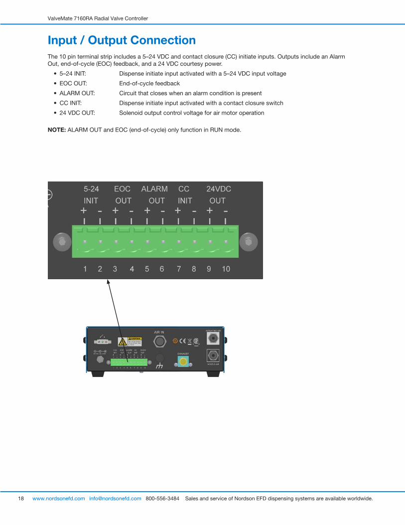
Input / Output ConnectionThe 10 pin terminal strip includes a 5–24 VDC and contact closure (CC) initiate inputs. Outputs include an Alarm Out, end-of-cycle (EOC) feedback, and a 24 VDC courtesy power.
• 5–24 INIT: Dispense initiate input activated with a 5–24 VDC input voltage
• EOC OUT: End-of-cycle feedback
• ALARM OUT: Circuit that closes when an alarm condition is present
• CC INIT: Dispense initiate input activated with a contact closure switch
• 24 VDC OUT: Solenoid output control voltage for air motor operation
NOTE: ALARM OUT and EOC (end-of-cycle) only function in RUN mode.

ValveMate 7160RA Radial Valve Controller
19www.nordsonefd.com [email protected] 800-556-3484 Sales and service of Nordson EFD dispensing systems are available worldwide.
Initiate ConnectionsThe 7160RA can be initiated by three inputs:
• 5–24 INIT: Application of 5–24 VDC to the 5–24 INIT terminals, pins 1+2
• CC INIT: Application of mechanical contacts on CC INIT terminals, pins 7+8
• Foot Pedal: Use of optional EFD foot pedal (P/N 7014865) plugged into foot pedal receptacle
A connection schematic is provided “I/O Connection Schematics” on page 20.
Alarm OUT ConnectionThe ValveMate 7160RA features an alarm output circuit. The Alarm OUT circuit closes when an alarm condition is present. The Alarm OUT circuit is a normally open electronic switch that can switch an external 5–24 VDC circuit to an external signaling device or PLC input. Maximum load is 100 mA, 5–24 VDC.
Alarm IN ConnectionThe ValveMate 7160RA offers an alternate use of the CC INIT initiate input for an external alarm signal. Refer to “How to Enable / Disable CC INIT I/O as an External Alarm Input” on page 14 to enable. When enabled as an alarm input, the CC INIT on pins 7 and 8 is connected to a normally closed switch, such as a low level reservoir float switch. When the CC INIT is enabled as an alarm input, the connections on pins 7 and 8 must be closed to initiate a valve actuation cycle.
End-of-Cycle (EOC) ConnectionThe ValveMate 7160RA features an EOC circuit to acknowledge an active valve actuation cycle. The EOC circuit is a normally closed electronic switch that can switch an external 5–24 VDC circuit to an external signaling device or PLC input. Maximum load is 100 mA, 5–24 VDC.
EOC signaling only functions when the ValveMate 7160RA is in the RUN mode. The EOC is normally closed in RUN mode while a valve actuation cycle is inactive. The EOC switch opens when the valve actuation cycle is initiated and closes when the valve actuation cycle is completed. The EOC signal only represents the valve actuation time and is not affected by the valve’s nozzle air delay time setting.
24 VDC OutputSolenoid output control voltage for air motor operation. The two wires from the 7160RA filter-regulator-lubricator assembly solenoid cable are connected to pins 9 and 10 on the 7160RA I/O connector.

ValveMate 7160RA Radial Valve Controller
20 www.nordsonefd.com [email protected] 800-556-3484 Sales and service of Nordson EFD dispensing systems are available worldwide.
I/O Connection Schematics
VOLTAGE INITIATE5-24 VDC
3 mA AT 5VDC19 mA AT 24 VDC
POWER IN24 VDC
0.63 A MAX.
INPUTS
OUTPUTS
++
SWITCH CLOSURES24 VDC MAX.100 mA MAX.
++
CC INITNO SWITCH19 mA MAX.
or
AIR MOTORCONTROL
+ -
ALARM INNC SWITCH19 mA MAX.
I/O external wiring diagram
I/O electrical schematic

ValveMate 7160RA Radial Valve Controller
21www.nordsonefd.com [email protected] 800-556-3484 Sales and service of Nordson EFD dispensing systems are available worldwide.
Air Connections
Air Input ConnectionConnect the ValveMate 7160RA to the plant air source through the supplied 7160RA filter-regulator-lubricator assembly (P/N 7360249). Use the supplied 6 mm tubing to connect the air between the 7160RA AIR IN push-in fitting (1) and the constant air output push-in fitting on the filter-regulator-lubricator assembly. Refer to “Typical Setup” on page 15.
Air Output ConnectionsConnect the valve actuating air hoses to the appropriate output push-in fittings: white hose to white-outlined push-in fittings for ACTUATING AIR (2); black hose to black-outlined push-in fittings for NOZZLE AIR (3).
3
12
IMPORTANTAir output push-in fittings have internal safety stop valves. Ensure that the valve air hoses are fully inserted into fitting to allow proper air flow.

ValveMate 7160RA Radial Valve Controller
22 www.nordsonefd.com [email protected] 800-556-3484 Sales and service of Nordson EFD dispensing systems are available worldwide.
Air Motor Lubrication SetupPrior to operating the controller / valve system, follow these steps for optimal results.
1. Remove the lubricator bowl by pushing up and turning counterclockwise.
2. Fill the lubricator bowl two-thirds full with the supplied air motor lubricant (CoilHose Pneumatics ATL004 air tool oil, P/N 7021820).
3. Reinstall the bowl by pushing up and turning clockwise.
The lubricator is preset to deliver the proper amount of lubricant.
4. Set the air pressure regulator to a minimum of 5.5 bar (80 psi).
5. Periodically empty the air motor lubricant captured in the oil recovery bowl. Do not reuse.
NOTES:
• The motor speed control is factory set to provide a rotor speed of approximately 2500 RPM. This setting can be changed if the rotor appears to start slow, runs slow, or if the optional dual valve kit is installed. Avoid excessive speed that can cause distortion of the spray pattern. Rotor speed has no effect on the total amount sprayed or spun onto cylinder wall ID.
• The filter bowl captures moisture from the plant air supply before it enters the controller / valve system.
Air pressure regulator adjustment knob
Lubricator bowl
Filter bowl
Oil recovery bowl
Filter-regulator-lubricator assembly (7160RA filter / regulator / lubricator, EFD P/N 7360249)

ValveMate 7160RA Radial Valve Controller
23www.nordsonefd.com [email protected] 800-556-3484 Sales and service of Nordson EFD dispensing systems are available worldwide.
Radial Spinner Valve Setup
InstallationPrior to installing this system, read the associated reservoir and 7860C radial spinner system installation guides to become familiar with the operation of all components of the radial spinner system.
1. Mount the radial spinner bracket using the rod provided or bolt it onto an appropriate mounting fixture. Follow these steps to install the radial spinner valve:
a. Slide the valve up into the bracket opening until it bottoms out at the actuating air fitting. Secure in place.
b. Install the special bent tip in the rotating luer lock adapter. Make sure the tip end is in the vertical position.
c. Slide the air motor into the bracket opening. Make sure the motor collet does not make contact at the bend of the dispense tip.
d. Insert the shaft into the collet. Set the tip approximately 0.5 mm (0.20 in.) from the spinning disc surface. Tip alignment should be 2.5 mm (0.100 in.) away the radial spinner shaft.
e. Realign the valve and motor in the bracket as needed to achieve recommended clearances.
2. Connect the fluid-feed hose to the reservoir outlet and the valve-inlet port using the appropriate fittings (supplied).
3. Connect the 4 mm diameter air hose from the valve to the 7160RA controller. The white connector goes to “ACTUATING AIR” port.
NOTE: Port “NOZZLE AIR” is not used for radial spinner installations. Turn off “NOZZLE AIR” by setting the regulator to 0 bar (0 psi).
4. Connect the white and black 6 mm diameter air hoses to the air motor assembly. Black connects to the F fitting, and white connects to the motor speed control fitting.
5. Connect the white and black 6 mm diameter hoses to the filter-regulator-lubricator assembly: black connects to the control valve and white connects to the oil recovery bowl.
6. Fill the fluid reservoir. After filling, secure the cover and connect the reservoir air pressure regulator to the air tee using the flexible air line (supplied). Attach the male quick-connect in the air line to the reservoir regulator and then attach the white quick-connect to the air tee. To pressurize the system, slide the shut-off valve in the air line toward the fluid reservoir.
7. Set the reservoir pressure regulator according to fluid viscosity: low for thin fluids [0.07–0.2 bar (1–3 psi)] and higher for thicker fluids.
8. Set the 752V-UHSS valve (or other appropriate valve model) stroke control to achieve a desired flow rate onto the spinning disc. Set the flow to approximately one drop per second.
9. Adjust the air motor RPM using the speed control knob. Turn the speed control knob clockwise to reduce RPM and counterclockwise to increase RPM.

ValveMate 7160RA Radial Valve Controller
24 www.nordsonefd.com [email protected] 800-556-3484 Sales and service of Nordson EFD dispensing systems are available worldwide.
To pressurize
To exhaust
0.5 mm(.020”)
2.5 mm(.100”)
NOTE: Set the tip approximately 0.5 mm (0.020 in.) from the spinning disc surface. Tip alignment should be 2.5 mm (0.100 in.) away from the radial spinner shaft.
Control valve
a
6
3
4
2
17
5
8
e
c
bd
Motor speed control
To control valve
Radial Spinner Valve Setup (continued)

ValveMate 7160RA Radial Valve Controller
25www.nordsonefd.com [email protected] 800-556-3484 Sales and service of Nordson EFD dispensing systems are available worldwide.
Final Setup Checklist — Radial Spinner ValveUpon initiation of the 7160RA radial system controller, air pressure is released to the air motor assembly (1) to begin spinning the radial disc assembly (2). Immediately following, a timed pulse of actuating air is released to the dispense valve (3) to apply fluid onto the spinning disc. The spinning disc causes the radial output to sweep around to apply an even band of fluid to the inner circumference of the cylinder (4).
When the timed actuating air from the 7160RA controller shuts off, the dispense valve closes, stopping fluid flow. An adjustable delay after the dispense cycle ensures that all fluid is dispersed after the valve closes, ensuring coating consistency from cycle to cycle.
From 7160RA filter-regulator-lubricator assembly
1
4
3
2

ValveMate 7160RA Radial Valve Controller
26 www.nordsonefd.com [email protected] 800-556-3484 Sales and service of Nordson EFD dispensing systems are available worldwide.
Radial Spray Valve Setup
To pressurize
To exhaust
2 7
3
15
8
4
Motor speed control
To control valve
6
InstallationPrior to installing this system, read the associated reservoir and 782RA spray valve installation guides to become familiar with the operation of all components of the radial spinner system.
1. Mount the valve using the 1/4-28 UNF tapped hole on the air cylinder body.
2. Connect the fluid feed hose to the reservoir outlet and to the valve inlet port using the appropriate fittings (supplied).
3. Connect the 4 mm diameter air hoses from the valve to the controller: white goes to the ACTUATING AIR port and black goes to the NOZZLE AIR port.
4. Connect the 6 mm diameter air hoses from the air motor to the filter-regulator-lubrication assembly. The white connects from the motor speed control fitting to the oil recovery bowl. The black connects from the “F” (marking on air motor) fitting to the control valve.
5. Fill the fluid reservoir. After filling, secure the cover and connect the reservoir air pressure regulator to the air tee using the flexible air line (supplied). Attach the black male quick-connect on the air line to the reservoir regulator and then attach the white quick-connect to the air tee.
6. To pressurize the system, slide the shut-off valve on the air line toward the fluid reservoir.
7. Set the reservoir pressure regulator according to fluid viscosity — low for thin fluids [0.07–0.2 bar (1–3 psi)] and higher for thick fluids.
8. Set the needle stroke control at one turn open. This is a starting point. The final setting will be determined by the desired flow rate.

ValveMate 7160RA Radial Valve Controller
27www.nordsonefd.com [email protected] 800-556-3484 Sales and service of Nordson EFD dispensing systems are available worldwide.
Final Setup Checklist — Radial Spray ValveInput-air pressure at 4.8 bar (70 psi) acts on a piston (1) that retracts the needle (2) from its nozzle seat (3), permitting fluid flow from the nozzle (4). At the same time, nozzle air from the ValveMate 7160RA controller is turned on and flows from the rotor air tube (5) across the fluid nozzle at a 70-degree angle.
This nozzle air creates a pressure drop around the nozzle, causing fluid to atomize into fine droplets and follow the direction of the nozzle air flow. The rotor, spinning at approximately 2500 RPM, causes the radial output to sweep around and evenly coat the inner circumference of the cylinder.
When the timed actuating air from the ValveMate 7160RA controller shuts off, the piston spring moves the needle onto the nozzle seat and shuts off fluid flow. An adjustable nozzle air delay ensures that all fluid is atomized after the valve closes, eliminating post-deposit spatter.
ClosedOpen
2
3
1
4
5

ValveMate 7160RA Radial Valve Controller
28 www.nordsonefd.com [email protected] 800-556-3484 Sales and service of Nordson EFD dispensing systems are available worldwide.
1 3 48
0–7.0 bar (0–100 psi)
0–7.0 bar (0–100 psi)
Replacement Parts1 7026518 KIT FITTING-4MM BULKHEAD
7026519 KIT POWER SUPPLY DC EXTERNAL 7100/7140/7160RA (Not Shown)
3 7026520 KIT VALVE SOLENOID 24VDC 1.8W WITH CONN
4 7026521 KIT CONN TERMBLOK PLUS IO 10POS 5.08MM
7026522 KIT BRACKET PIVOT, 7140/7160RA (Not Shown)
6 7014866 KIT, GAUGE 0–7.0 BAR (0–100 PSI)
7 7026525 KIT, 7160 PRECISION REGULATOR 0–7.0 BAR (0–100 PSI)
8 7026524 KIT M4X20MM THUMB SCREW ASSEMBLY
7360249 7160RA FILTER REGULATOR LUBRICATOR (Not Shown)
7026543 KIT DC CABLE ASSEMBLY-2M-LOCKING CONN (Not Shown)
7026544 KIT PANEL MOUNT 7100/7140/7160RA (Not Shown)
7021820 AIR MOTOR OIL, 4 OZ (Not Shown)
6
7

ValveMate 7160RA Radial Valve Controller
29www.nordsonefd.com [email protected] 800-556-3484 Sales and service of Nordson EFD dispensing systems are available worldwide.
Troubleshooting
LED toggles between and pressure value and will not accept initiate signal.
Unit is not responding to the initiate signal.
Timer is inoperative.
LED is blinking
–
Trouble Possible cause and correction
Air pressure to the ValveMate 7160RA has dropped below 4.1 bar (60 psi). Raise the input pressure to 4.8 bar (70 psi). Press MODE button to reset.
If problem persists, make sure devices such as air cylinders are not causing a pressure drop in the ValveMate 7160RA input air line.
Check to make sure the unit is not in a mode other than RUN. Response delay in pneumatic circuit does not allow the valve to open when time is set at or below 0.010 seconds. Increase time. The signal must break cleanly before the next signal is initiated.
Check to make sure the unit is not in the steady / timer override function.
External alarm is enabled and circuit is open. Check cause for fault or disable. Refer to “How to Enable / Disable CC INIT I/O as an External Alarm Input” on page 14.

NORDSON EFD ONE YEAR LIMITED WARRANTY
Nordson EFD products are warranted for one year from date of purchase to be free from defects in material and workmanship (but not against damage caused by misuse, abrasion, corrosion, negligence, accident, faulty installation or by dispensing material incompatible with equipment) when the equipment is installed and operated in accordance with factory recommendations and instructions. Nordson EFD will repair or replace free of charge any part of the equipment thus found to be defective, on authorized return of the part prepaid to our factory during the warranty period. In no event shall any liability or obligation of Nordson EFD arising from this warranty exceed the purchase price of the equipment. This warranty is valid only when oil-free, clean, dry, filtered air is used.
Nordson EFD makes no warranty of merchantability or fitness for a particular purpose. In no event shall Nordson EFD be liable for incidental or consequential damages.
For Nordson EFD sales and service in over 40 countries, contact Nordson EFD or go to www.nordsonefd.com.
Global East Providence, RI USA 800-556-3484; +1-401-431-7000 [email protected]
Europe Dunstable, Bedfordshire, UK 0800 585733; +44 (0) 1582 666334 [email protected]
Asia China: +86 (21) 3866 9006; [email protected] India: +91 80 4021 3600; [email protected] Japan: +81 03 5762 2760; [email protected] Korea: +82-31-736-8321; [email protected] SEAsia: +65 6796 9522; [email protected]
The Wave Design is a trademark of Nordson Corporation. ©2018 Nordson Corporation 7029856 v092518