vag 1383a transmission jack
TRANSCRIPT

42-1
Rear axle, servicing Rear axle, removing and installing
Special tools and equipment
VAG 1383A transmission jack
VAG 1869 Brake filling and bleeding unit

42-2
Removing
Note:
Do not remove bearing bracket to remove rear axle
- Remove bolts -1- with vehicle standing on its wheels (raise vehicle until bolts are accessible).
- Raise vehicle further to relieve coil spring pressure.
- Remove wheels.
- Unclip brake cable (arrows).
- Remove clips -2- on both sides.
- Disconnect brake lines.
42-3
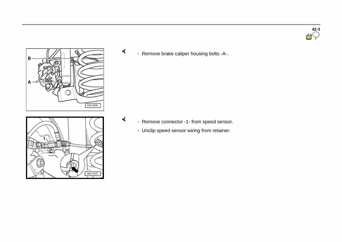
- Remove brake caliper housing bolts -A-.
- Remove connector -1- from speed sensor.
- Unclip speed sensor wiring from retainer.

42-4
- Support rear axle.
For example, with transmission jack VAG 1383 A
Installing
Repair Manual, Brake System, Repair Group 47
Grease bonded rubber bushings
- Remove bearing bracket bolts -1- on both sides of rear axle, and lower rear axle.
- Bleed brakes.
- Grease bonded rubber bushings with assembly paste before installing rear axle.
- Install in reverse sequence
- Check steering wheel position during test drive.
- Check wheel alignment if steering wheel is not in straight ahead position .
Tightening torque:
Shock absorber to body
Use new bolts!
75 Nm (55 ft lb)
Bearing bracket to rear axle 80 Nm (59 ft lb)

Use new nuts and bolts!
42-5
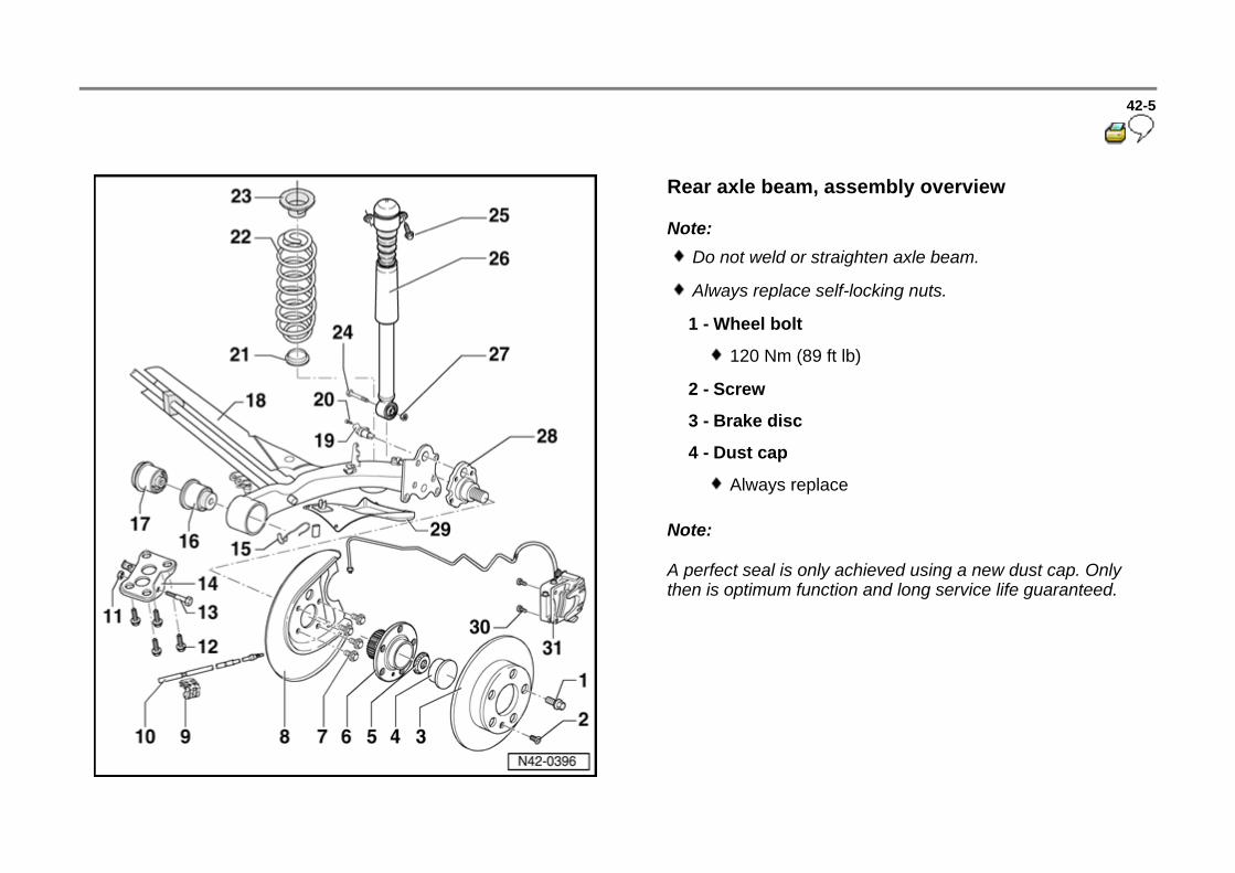
Rear axle beam, assembly overview
Note:
Note:
A perfect seal is only achieved using a new dust cap. Only then is optimum function and long service life guaranteed.
Do not weld or straighten axle beam.
Always replace self-locking nuts.
1 - Wheel bolt
120 Nm (89 ft lb)
2 - Screw
3 - Brake disc
4 - Dust cap
Always replace

42-6
Note:
5 - Self-locking 12-point nut
175 Nm (129 ft lb)
Always replace
6 - Wheel hub with wheel bearings
Wheel bearing/hub are installed together in housing.
Wheel bearing/hub unit is maintenance and adjustment free. Adjusting and servicing are not possible!
7 - Bolt
60 Nm (44 ft lb)
Always replace
8 - Splash plate
9 - Bracket, parking brake cable
10 - Parking brake cable
11 - Self-locking nut
80 Nm (59 ft lb)
Always replace

42-7
Note:
Use this repair method on one weld nut only each side!
12 - Bolt
75 Nm (55 ft lb)
Always replace
If weld nut threads in long member are damaged, repair with Heli-coil.
13 - Bolt
80 Nm (59 ft lb)
Always replace
14 - Bearing bracket
Check and if necessary adjust rear axle toe after installation
If possible, do not loosen when removing rear axle
15 - Parking brake cable clip
16 - Bonded rubber bushing
Removing and installing Page 42-11

42-8
17 - Hydraulic rubber bonded bushing
18 - Axle beam
Stub axle contact surfaces and threaded holes are to be free of paint and dirt
19 - ABS wheel speed sensor
20 - Socket head bolt
8 Nm (70 in. lb)
21 - Spacer bushing
Material: Zinc
Check for damage
22 - Coil spring
Determine part number from parts catalog

42-9
23 - Spring seat
24 - Bolt
60 Nm (44 ft lb)
Always replace
25 - Bolt
75 Nm (55 ft lb)
Always replace
26 - Shock absorber
Functional check
Page 42-21

42-10
Repair Manual, Brake System, Repair Group 46
Repair Manual, Brake System, Repair Group 47
27 - Nut
Axle beam must be centered when tightening nut
Load vehicle with one person when tightening.
28 - Stub axle
Do not attempt to straighten
Do not re-cut threads
29 - Stone protection plate
30 - Bolt
65 Nm (48 ft lb)
Always replace
31 - Brake caliper
Servicing

42-11
Bonded rubber bushings, removing and installing
Special tools and equipment
3301 Assembly tool
3346 Assembly tool
3416/1 Press piece
3416/2 Press piece
3416/3 Support tube
42-12
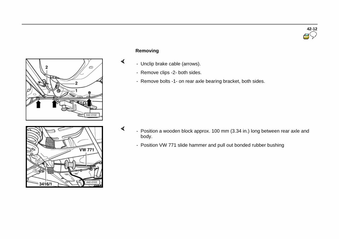
Removing
- Unclip brake cable (arrows).
- Remove clips -2- both sides.
- Remove bolts -1- on rear axle bearing bracket, both sides.
- Position a wooden block approx. 100 mm (3.34 in.) long between rear axle and body.
- Position VW 771 slide hammer and pull out bonded rubber bushing

42-13
Installing
Bonded rubber bushing has mark -1- on face.
Mark must align with edge (arrow) on trailing arm -2-.
- Mark position of mark -1- on bonded rubber bushing.
- Assemble special tool with bonded rubber bushing.

42-14
Continue rear axle installation in reverse sequence
- Install bonded rubber bushing and special tool on rear axle.
- Ensure mark aligns with trailing arm edge.
- Install (pull in) bonded rubber bushing by turning spindle.
- Check position of bonded rubber bushing after installing.
Tightening torque:
Bearing bracket to rear axle
Use new nuts and bolts!
80 Nm (59 ft lb)

42-15
Hydraulic bonded rubber bushings, removing and installing
Bushings -2- cannot be pressed out or in with current shop tools.
If bushing -2- is damaged, the rear axle beam must be replaced.
Vibration damper -4- is only on axles equipped with Hydraulic bonded rubber bushings (axles with solid rubber bushings do not have damper).
Rear axle beam is supplied as a spare part assembly (including hydraulic bonded rubber bushings).
42-16
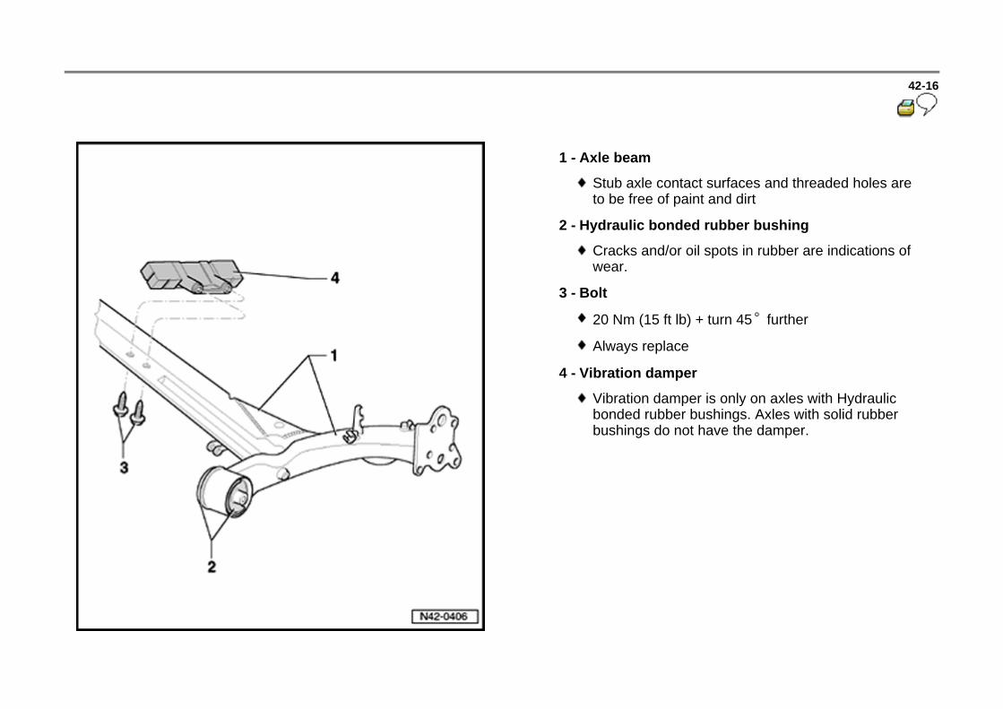
1 - Axle beam
Stub axle contact surfaces and threaded holes are to be free of paint and dirt
2 - Hydraulic bonded rubber bushing
Cracks and/or oil spots in rubber are indications of wear.
3 - Bolt
20 Nm (15 ft lb) + turn 45 further
Always replace
4 - Vibration damper
Vibration damper is only on axles with Hydraulic bonded rubber bushings. Axles with solid rubber bushings do not have the damper.

42-17
Shock absorber/spring, removing and installing
Special tools and equipment
VAG 1752 Strut holder
VAG 1752/3 Strut adaptor
VAG 1752/9 adaptor
Spring, removing
- Position spring holder -1-.
- Compress coil spring enough to remove.
- Remove spring.
1 - VAG 1752/1 Strut spring tool
2 - VAG 1752/9 adaptor
3 - VAG 1752/3 Strut adaptor
42-18
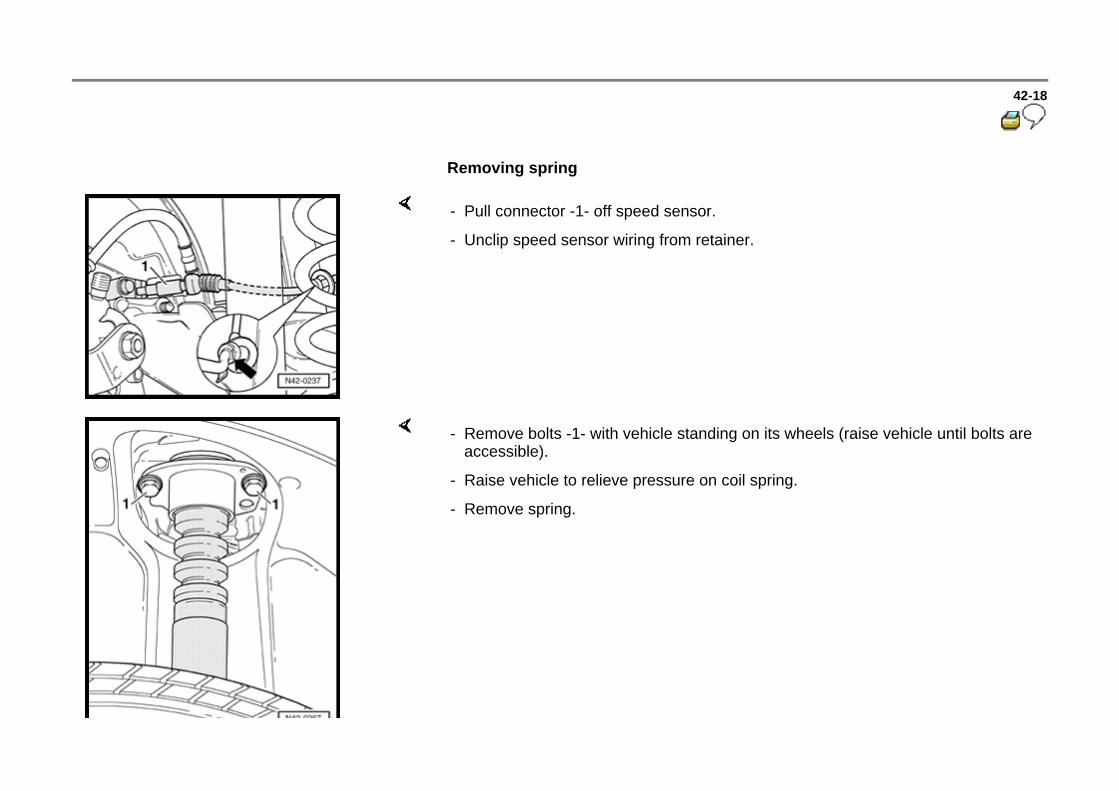
Removing spring
- Pull connector -1- off speed sensor.
- Unclip speed sensor wiring from retainer.
- Remove bolts -1- with vehicle standing on its wheels (raise vehicle until bolts are accessible).
- Raise vehicle to relieve pressure on coil spring.
- Remove spring.

42-19
Installing spring
- Ensure spacer bushing (zinc) is not damaged. Replace if necessary.
- Install spring together with spring seat.
- Loosen spring and remove spring compressor. Observe installation position!
End of spring (arrow) must lie against stop on spring seat.
Shock absorber, removing
- Remove bolts -1- with vehicle standing on its wheels (raise vehicle until bolts are accessible).
42-20
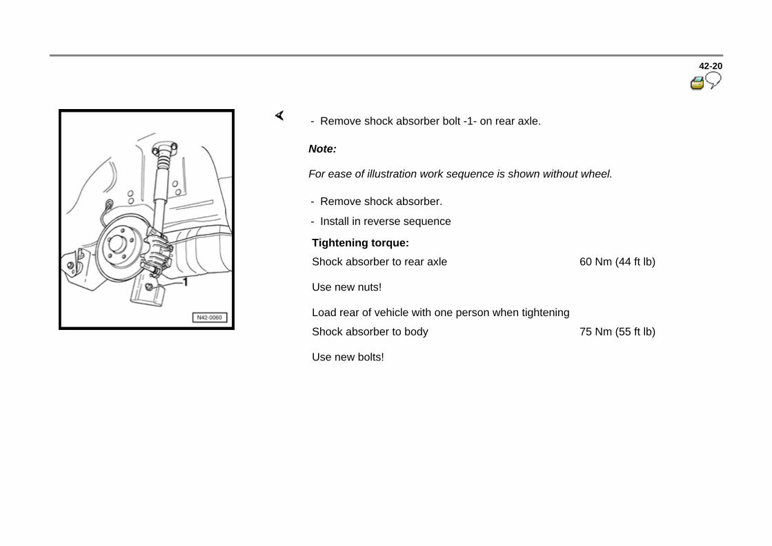
Note:
For ease of illustration work sequence is shown without wheel.
- Remove shock absorber bolt -1- on rear axle.
- Remove shock absorber.
- Install in reverse sequence
Tightening torque:
Shock absorber to rear axle
Use new nuts!
Load rear of vehicle with one person when tightening
60 Nm (44 ft lb)
Shock absorber to body
Use new bolts!
75 Nm (55 ft lb)