vacuum systems operation eic training and refresher course
TRANSCRIPT

Liam Worth JET EiC Training & Refresher Course 26th April 2007
Vacuum Systems Operation
EiC Training and Refresher Course
26th April 2007

Liam Worth JET EiC Training & Refresher Course 26th April 2007
Contents
1. Introduction2. Pumps and pumping on JET
Primary VolumesPrimary PumpsSecondary PumpsVacuum DiagnosticsVessel Conditioning (covered in separate talk)The interspace system
3. JET normal conditionsPlasma operationsFuelling (covered in a separate talk)
4. JET abnormal conditionsLoss of vacuum and leaks

Liam Worth JET EiC Training & Refresher Course 26th April 2007
Introduction• JET is the largest magnetically confined fusion device in the world (and the
only one capable of full tritium operations)
• 200 m3 vacuum vessel
• Carbon tiles on plasma facing components (high surface area!)
• Large area Carbon divertor region in vessel
• 100’s Kms of lip welds
• ~120 ports with windows/diagnostics/ feed-throughs to the outside world
• Water cooling in vessel components
Still manage to pump to better the 1 x 10⁻⁷ mbar!

Liam Worth JET EiC Training & Refresher Course 26th April 2007
Introduction• Reliable plasma operations require that the vessel conditions be
good (subjective)
• More over ; the vessel conditions must be controlled so that :– Vast majority of the plasma is fuel– Chosen gases can be injected as required for experiments– Impurities kept to minimum possible level (better than 10-9 mbar)
• To avoid density limit disruptions• To ensure that machine performance is repeatable -
Extremely important

Liam Worth JET EiC Training & Refresher Course 26th April 2007
Introduction
• The overall air all leak rate on JET is estimated to be ~1 x 10⁻⁴
mbarls-1 BUT, adsorbed impurities are readily released from the carbon ‘sponge’ by radiation and particle induced de-sorption.
• In JET, and other divertor machines, the during a shot the plasma can come into contact with the plasma facing components.Therefore we want:– Clean well conditioned walls (low Z materials)– High pumping speed to remove impurities– Pumps that can also deal with exhaust, i.e. Helium
Poor conditioning of the walls can lead to unreliable/ poor breakdown of the plasma and density limit disruptions wasting
operational time!

Liam Worth JET EiC Training & Refresher Course 26th April 2007
Introduction
When the plasma collapses (disrupts) the electric current generated in the plasma can interact with the magnetic field generated from the confinement coils.
This interaction results in a force
During Disruptions Forces can be:
> 400 Tonnes for 10 ms Vertical >200 Tonnes for 10 ms Horizontal Can cause a movement of the Vacuum Vessel up to 7 mm with
acceleration of 3g So the vacuum vessel is restrained by large brakes!

Liam Worth JET EiC Training & Refresher Course 26th April 2007
Introduction

Liam Worth JET EiC Training & Refresher Course 26th April 2007
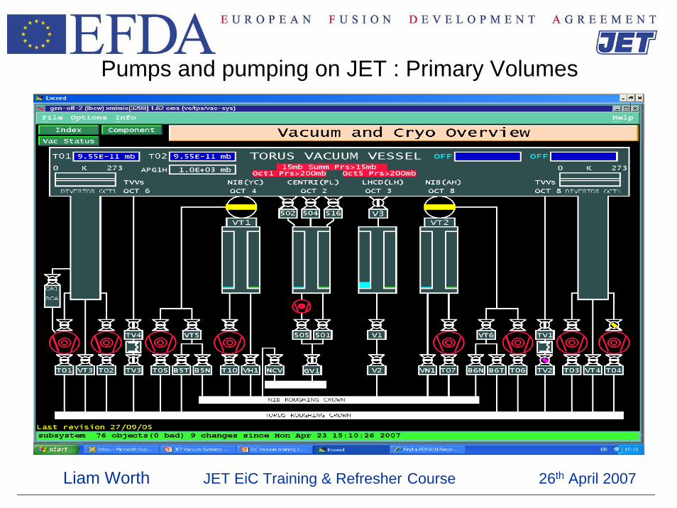
Pumps and pumping on JET : Primary Volumes1. Main Vacuum Vessel 200 m3 Nominal but 187 m3 Actual due to
internal components. Surface Area Huge c 106 m2 Carbon Tiles, Heat Shields. 100’s windows and ports. All welded construction in 8 octants.
2. 2 Neutral Injector Boxes at 50 m3 each with water cooled shielding and bending magnets.
3. 2 Rotary Valves at 5 m3 each with copper water cooled internal shielding.
4. 1 Lower Hybrid Launcher at 10 m3 volume with 48 waveguides.
5. 1 Pellet Centrifuge Injector at 5 m3 volume.
6. 2 Pumping Chambers at 5 m3 each
Liam Worth JET EiC Training & Refresher Course 26th April 2007
Pumps and pumping on JET : Primary Volumes

Liam Worth JET EiC Training & Refresher Course 26th April 2007
Pumps and pumping on JET : Primary Pumps Pumps used as primary evacuation devices at JET fall into two categories. Those which retain the gasses they pump and those which exhaust to the
secondary pumps either continuously or in batches.
In the first category are Ion Pumps Non Evaporatable Getter (NEG) Pumps Used mainly for pumping small volumes with low gas load
In the second category are Turbo-molecular Pumps Cryo-pumps Roots Used for pumping the larger volumes coupled with high gas load.

Liam Worth JET EiC Training & Refresher Course 26th April 2007
Pumps and pumping on JET : Primary PumpsIon & NEG
Ion Pumps are used in a few places at JET (e.g. IVIS) where little outgassing is experienced and the system is not often disturbed.They are placed away from the Torus magnetic field Unfortunatelytheir mode of operation is such that any Tritium is retained in the pump and is hard to get rid of.
NEG pump by chemically sorbing active gasses on to their elements and are used in closed volumes such as RF vacuum transmission lines where the main outgassing is Hydrogen.
They must be regenerated by heating to high temperature at intervals to keep their pumping efficiency high.

Liam Worth JET EiC Training & Refresher Course 26th April 2007
Pumps and pumping on JET : Primary PumpsTurbo Pumps
Running continuously, exhausting via ML1 and ML2 to AGHSFour 2000 ls-1 turbo pumps on the Torus de-coupled mechanically from
the Torus to avoid damage during disruptions.
One 2000 ls-1 turbo pump on each Rotary High Vacuum Valve.
One 2000 ls-1 turbo pump on each NIB Box.
Most diagnostic vacuum systems have 500 ls-1 turbo pumps
Turbo-molecular pumps used on the Torus or NIBs must be Tritium Compatible i.e. all metal, low amounts of oil grease etc

Liam Worth JET EiC Training & Refresher Course 26th April 2007
Pumps and pumping on JET : Primary PumpsTurbo Pumps

Liam Worth JET EiC Training & Refresher Course 26th April 2007
Pumps and pumping on JET : Primary PumpsCryopumps
1. Cryopumps are used at JET to pump large amounts of gases such as Deuterium and Hydrogen. They collect gas in batches
2. Cryopumps which have large cold panels to condense and freeze gasLN2 and LHe cooling required
3. Regenerate by warming up the LHe / LN2cooled panels Inventory limited
There are six cryopumps in total on JET comprising:6,000,000 ls-1 in each NIB100,000 ls-1 in the Torus Divertor Region - two separate pumps50,000 ls-1 in the Lower Hybrid system10,000 ls-1 in the Pellet Centrifuge

Liam Worth JET EiC Training & Refresher Course 26th April 2007
Pumps and pumping on JET : Primary PumpsCryopumps
Cold panels in a domestic freezerAt 273K water vapour is collected as frostJET cryopanelsAt -269°C (5K) everything else collects as frost (except helium – pumped by turbos)Need to be defrosted (regeneration)Strict inventory limit - pumping explosive gases

Liam Worth JET EiC Training & Refresher Course 26th April 2007
Pumps and pumping on JET : Primary PumpsCryopumps : Regenerations
1. Generally LHe panels on NIBs, PD and LH are regenerated weekly with LH regenerated onto PD
2. Generally LN2 panel only regenerated for vessel warm up or loss of cryogen – Do not want to release condensed water and spoil vessel conditions!
LHe panels are regenerated before the allowed gas inventory is exceeded to avoid explosion hazard.
e.g. Maximum inventory on NIB LHe panels 300 bar litres.
Liam Worth JET EiC Training & Refresher Course 26th April 2007
Pumps and pumping on JET : Primary Pumps Roots
Currently there are no Roots pumps working as primary pumps on JET
To be installed at Part of the HFPI project are two roots pumps in the torus hall
1. 7000 m3/hr under octant 2
2. 1000 m3/hr to pump Very high field side track on Torus

Liam Worth JET EiC Training & Refresher Course 26th April 2007
Pumps and pumping on JET : Primary Pumps Helium pumping
1. Helium is not pumped by the LHe Cryopanels,
Argon condenses on the LHe panel and ‘traps’ Helium at JET we have an Argon frosting system for this.
2. Helium is pumped by the turbo pumps.

Liam Worth JET EiC Training & Refresher Course 26th April 2007
Pumps and pumping on JET : Secondary Pumps AGHS
The AGHS complex consists of the following major subsystems :-
1 Cryo-genic Forevacuum System (CF)2 Mechanical Forevacuum System (MF)3 Exhaust De-tritiation System (EDS)4 Cryo-distillation System (CD)5 Impurity Processing (IP)6 Intermediate Storage System (IS)7 Product Storage System (PS)8 Gas Introdustion System (GI)
This system now deals with all the exhaust gas from various sources on JET such as cryo-regenerations, TMP exhaust and diagnostic exhaust.
No gas goes direct to atmosphere

Liam Worth JET EiC Training & Refresher Course 26th April 2007
Pumps and pumping on JET : Secondary Pumps diagnostic crown
The diagnostic crown, like ML1 & 2, is of all welded construction.
Has a volume of ~1.5m3 provided a N2 purged exhaust root for the many diagnostic backing pumps on JET.
Kept at ~900 mbar with a 160 m3hr-1 Screw pump.
See :MOM/0420/001- Description of the Diagnostic Exhaust Crown (DEC)MOGDOC 3.23 - Loss of Diagnostic Exhaust Crown Pumping

Liam Worth JET EiC Training & Refresher Course 26th April 2007
Pumps and pumping on JET : Secondary Pumps diagnostic crown

Liam Worth JET EiC Training & Refresher Course 26th April 2007
Vacuum Diagnostics : Gauges
There are 4 main types of Vacuum Gauges installed on the JET machine.
1. Baratrons. These are capacitance gauges They are true reading gauges which are independent of gas type. Pressure range from 1000 mbar to 10-3 mbar
2. Pirani. These are thermal conductivity gauges. They are gas dependent but are calibrated as nitrogen equivalent. Pressure range from 100 mbar to 10-3 mbar.
3. Penning. Cold cathode ion gauges. Also dependent on gas. Calibrated for Hydrogen species. Pressure range from 10-3 to 10-9
mbar.4. Ion. Hot cathode ion gauges. Also gas dependent and are calibrated
as nitrogen equivalent. Pressure range from 10-4 to 10-10 mbar.

Liam Worth JET EiC Training & Refresher Course 26th April 2007
Vacuum Diagnostics : Gauges
Baratron capacitance manometers are usually stand-alone
transducers typically requiring a ±15 volt power supply and deliver a 0-10 volt pressure signal that is directly proportional to pressure.
Pressure at inlet causes deflection of diaphragm changing capacitance

Liam Worth JET EiC Training & Refresher Course 26th April 2007
Vacuum Diagnostics : Gauges
Pirani – thermal conductivity gauge. Thermal conductivity of filament
proportional to gas pressure.
Thermionic and cold cathode (Penning) ionisation type. Energetic electrons ionise
gas. Collected current proportional to gas pressure

Liam Worth JET EiC Training & Refresher Course 26th April 2007
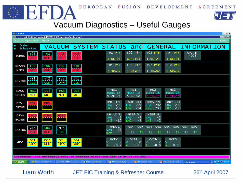
Vacuum Diagnostics – Useful Gauges
T0n pressure measurement (n=turbo pump number)
VC/TTn-PEN<PRS:001
VC/TTn-PIR<PRS:001
Liam Worth JET EiC Training & Refresher Course 26th April 2007
Vacuum Diagnostics – Useful Gauges

Liam Worth JET EiC Training & Refresher Course 26th April 2007
Vacuum Diagnostics – Useful Gauges
VC/BARTRN-1H<PRSBaratron on Octant 1 (also 5H) torus total pressure. Displayed on Vacuum overview mimic
VC/DECP-PRS<P1Baratron Pressure measurement of Diagnostic crown. Displayed on Diagnostic crown mimic
VC/DCP-P1<PRSPirani measurement of Divertor coil case pressure. Displayed on PD case pumping mimic

Liam Worth JET EiC Training & Refresher Course 26th April 2007
Vacuum Diagnostics – Useful Gauges

Liam Worth JET EiC Training & Refresher Course 26th April 2007
Vacuum Diagnostics – RGA
4 Main Residual Gas Analysers on JET (quadrupoles)1. QS1 – Torus main spectrometer2. QS2 – Torus backup spectrometer. Both QS1 & 2 can sample
torus atmosphere through valve GA1. Useful for GDC and vacuum analysis at high pressure
3. QS3 – NIB 8 Spectrometer4. QS4 – NIB 4 Spectrometer
Can be used as qualititative tools. Periodic calibration of RGA required for quantitative analysis.

Liam Worth JET EiC Training & Refresher Course 26th April 2007
Vacuum Diagnostics – RGA
The RGA is an ionisation gauge with mass filtering. A combination of DC and RF (~few MHz) applied to rods
allowing only species with specific mass/charge to pass to detector.

Liam Worth JET EiC Training & Refresher Course 26th April 2007
Vacuum Diagnostics – RGA
Large air leak on JET
Mass 28 : Nitrogen 100%
Mass 32 : Oxygen 20%
Mass 40 : Argon 1%
Carbon gettering will suppress oxygen peak when
vessel is above ~ 80°C. Beryllium also getters
oxygen

Liam Worth JET EiC Training & Refresher Course 26th April 2007
Vacuum Diagnostics – RGA
Mass 20 indicating Neon in chamber –
probably from interspace system

Liam Worth JET EiC Training & Refresher Course 26th April 2007
Vacuum Diagnostics – RGA
Typical JET spectrum D2 operationsMass 4 – D2
Hydrocarbon groups
C1 C2 C3Many experts make
for subjective interpretation of
spectra

Liam Worth JET EiC Training & Refresher Course 26th April 2007
Vessel Conditioning
There are a number of systems on JET used to condition the vessel to improve the quality of vacuum.
There include :
1. Glow Discharge Cleaning.2. Beryllium evaporation.
These systems are covered in a separate talk by L worth

Liam Worth JET EiC Training & Refresher Course 26th April 2007
The interspace system
Items at high risk of vacuum failure are protected by the interspace system. The system protects the following :
• Windows 114• Bellows 24•Internal volumes 30• Feedthroughs 48• Sundry Others 10• Be. Evaporators 4• Total 330
Neon filled interspace (500 mbar)
Air
Pressure gauge
Windows
Vacuum

Liam Worth JET EiC Training & Refresher Course 26th April 2007
The interspace system
If a leak is suspected (from RGA) a visual inspection of the interspace system is carried out by Vacuum Group

Liam Worth JET EiC Training & Refresher Course 26th April 2007
JET normal conditions Plasma operations
During a deuterium operational day there may be up to 50 pulses with :
• Turbo pumps run continuously– Gas injection to the Torus - various locations
• Torus at 200°C continuously• Cryopanels typically regenerated once a week
– LH regenerated onto pumped divertor• GDC and Be evaporation typically once per week
Liam Worth JET EiC Training & Refresher Course 26th April 2007
JET normal conditions Plasma operations
In tritium operations, you might expect 15 or 20 pulses in a day.
• Turbo pumps run continuously– Gas injection to the Torus - various locations. Tritium through
GIM 15• Torus at 200°C continuously• Gas inventory strictly controlled and accounted for• Cryopanels regenerated every day• Full tritium accountancy every day• GDC and Be evaporation as required• Some diagnostic systems isolated

Liam Worth JET EiC Training & Refresher Course 26th April 2007
JET normal conditions Fuelling
Fuelling Gases:-Hydrogen, Deuterium,4Helium,Tritium
Impurities for:-DiagnosticsControl of plasma edgeRF couplingWall deposition experiments3Helium,13CH4, Argon, Xenon, Krypton, Nitrogen
SilaneCovered in separate talk by
L Worth

Liam Worth JET EiC Training & Refresher Course 26th April 2007
Loss of Vacuum incidents on JET
What is loss of Vacuum?
Could be defined as a rise in pressure to the point where operations are not possible.i.e. By ingress of air, water, cryogen's, SF6, neon or any other gas or fluid which has an adverse effect on Torus or NIB pressure.
Tentative maximum ingress rate allowable is 5 x 10⁻⁴
mbar.ls-1 before halt called to operations. This is very subjective!

Liam Worth JET EiC Training & Refresher Course 26th April 2007
Loss of Vacuum incidents on JET
The following fluids have the potential for ingress into the vacuum vessel.
1. Air from a leak to atmosphere or an RF AVS bellows failure.2. Water from failure of a cooling line.3. Nitrogen either from vent gas or an internal cryogen leak.4. Helium from an internal cryogen leak.5. Neon from an interspace failure.6. SF6 from a LH double window leak.7. Galden from a leak in the divertor coil.
Note that 6. and 7. are unlikely but would damage the catalysts in AGHS.
Reconditioning of the vessel after loss of vacuum incident can take ~2 weeks

Liam Worth JET EiC Training & Refresher Course 26th April 2007
Loss of Vacuum incidents on JET
Three levels of ingress for different pressure regimes are defined on JET they are,
1. Level 1 - Ingress up to 1 mbar.ls-1
2. Level 2 - Ingress from 1 mbar.ls-1 to 102 mbar.ls-1
3. Level 3 - Ingress above 102 mbar.ls-1

Liam Worth JET EiC Training & Refresher Course 26th April 2007
Loss of Vacuum incidents on JET
Level 1 Scenario Ingress up to 1 mbar.ls-1 : Most Common on JET
At maximum a pressure in the Torus of 10-4 mbar with turbomolecular pumps and 10-5 mbar with the cryopump operational.
Expected scenario is :1. Cryopump is loading at maximum rate of 3.6 bar.l/hour of ingress
gas.2. No increase in backing line pressure if cryopump on.3. Backing line pressure 10-2 mbar with conventional pumps only.3. Torus RGA operational.
4. Torus turbomolecular pumps operational.

Liam Worth JET EiC Training & Refresher Course 26th April 2007
Loss of Vacuum incidents on JETLevel 1 Scenario Ingress up to 1 mbar.ls-1 : Actions
The following actions are advisable.
1. Call out the vacuum on-call officer.2. Inform AGHS of the rate and species of ingress. This may be
ascertained from the RGA.3. Follow the advice of AGHS on what to do next. They have to deal
with the gas.4. Prepare to possibly regenerate cryo-pumps.5. Prepare to cool down vessel if necessary.6. Get out the leak detector!

Liam Worth JET EiC Training & Refresher Course 26th April 2007
Loss of Vacuum incidents on JETLevel 2 - Ingress from 1 mbar.ls-1 to 102 mbar.ls-1
At maximum a pressure in the Torus of 10-2 mbar with turbomolecular pumps and 10-3 mbar with the cryopump operational.
Expected scenario is :1. Cryopump is loading at maximum rate of 3.6 x 10² bar.lh-1 of
ingress gas.2. Backing line pressure 10-2 mbar with cryopump, 10-1 mbar without.3. Torus RGA not operational normally but possible with T01 top
valve shut and GA1 open.4. Torus turbomolecular pumps operational but not recommended at
this pressure.

Liam Worth JET EiC Training & Refresher Course 26th April 2007
Loss of Vacuum incidents on JET
Level 2 - Ingress from 1 mbar.ls-1 to 102 mbar.ls-1 : Actions
The following actions are advisable.1. Call out the vacuum on-call officer. 2. Inform AGHS of the rate and species of ingress. This may be
ascertained from the RGA if operational.3. Follow the advice of AGHS on what to do next. They have to deal
with the gas.4. Prepare to regenerate cryo-pumps.5. Prepare to cool down vessel.6. Prepare to close down turbomlecular pumps if torus pressure
riseover 10-1 mbar.

Liam Worth JET EiC Training & Refresher Course 26th April 2007
Loss of Vacuum incidents on JETLevel 3 - Ingress above 10-2 mbar.ls-1
Out of control – Damage limitation
1. Torus cryopumps will spontaneously regenerate. 2. NIB cryopumps will also regenerate if RHVV are open or have large seal
leaks3. All turbo molecular pumps will trip.4. At 15 mbar, Draining and Refilling System will operate.5. At 200 mbar the turbo bypass valves will open. This is a hard wired
interlock and cannot be over-ridden.6. At 250 mbar EDS will automatically route to pump ML1 and ML2. As the
pressures in ML1 & 2 approach atmosphere non-return valves will open and EDS will remove up to 500m3hr-1. This will protect the vessel from ANY foreseeable event.
7. If atmospheric pressure were still to be exceeded – MOST unlikely – the Torus bursting disc is the final protection.

Liam Worth JET EiC Training & Refresher Course 26th April 2007
Loss of Vacuum incidents on JETRelated documents
MOGDOC 3.26 - Unplanned Torus Vacuum Pressure Rise
MOGDOC17.06 - Operation of KS1 Beamline Torus ValveMOGDOC 9.11 - Vacuum Vessel Temperature Change ChecklistMOGDOC 3.23 - Failure of the RF Double Window (DCF)

Liam Worth JET EiC Training & Refresher Course 26th April 2007
Finally……
• On the whole, JET vacuum is the cause of little concern when JET is operational, though production of a decent vacuum can be difficult -especially during a restart.
• Most of the vacuum equipment runs smoothly and reliably.
• Dedicated team of crack vacuum experts and vacuum instrumentation control specialists are on call 24 hours a day, 365 days a year, to ensure that vacuum problems account for little loss of operational time.