vacuum resource guide - vacuum automation equipment ... · pdf filevacuum resource guide bimba...
TRANSCRIPT
Vacuum Resource Guide
Bimba Vaccon u 9 Industrial Park Rd u Medway, MA 02053 u 508-359-7200 u www.vaccon.com
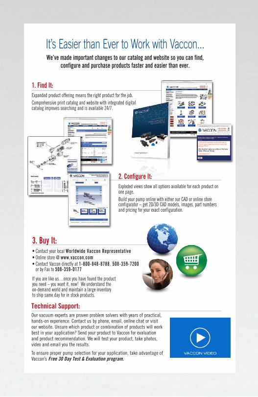
Technical Support: Our vacuum experts are proven problem solvers with years of practical, hands-on experience. Contact us by phone, email, online chat or visit our website. Unsure which product or combination of products will work best in your application? Send your product to Vaccon for evaluation and product recommendation. We will test your product, take photos, video and email you the results.
To ensure proper pump selection for your application, take advantage of Vaccon’s Free 30 Day Test & Evaluation program.
It’s Easier than Ever to Work with Vaccon...We’ve made important changes to our catalog and website so you can find,
configure and purchase products faster and easier than ever.
3. Buy It:• Contact your local Worldwide Vaccon Representative• Online store @ www.vaccon.com• Contact Vaccon directly at 1-800-848-8788, 508-359-7200
or by Fax to 508-359-0177
If you are like us…once you have found the product you need – you want it, now! We understand the on-demand world and maintain a large inventory to ship same day for in stock products.
2. Configure It:Exploded views show all options available for each product on one page.Build your pump online with either our CAD or online store configurator – get 2D/3D CAD models, images, part numbers and pricing for your exact configuration.
1. Find It:Expanded product offering means the right product for the job.Comprehensive print catalog and website with integrated digital catalog improves searching and is available 24/7.
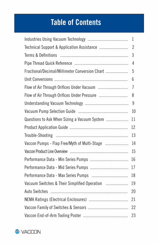
Table of Contents
Industries Using Vacuum Technology ...................................... 1
Technical Support & Application Assistance ........................... 2
Terms & Definitions ................................................................ 3
Pipe Thread Quick Reference ................................................... 4
Fractional/Decimal/Millimeter Conversion Chart ..................... 5
Unit Conversions ..................................................................... 6
Flow of Air Through Orifices Under Vacuum ............................ 7
Flow of Air Through Orifices Under Pressure ........................... 8
Understanding Vacuum Technology ......................................... 9
Vacuum Pump Selection Guide ............................................... 10
Questions to Ask When Sizing a Vacuum System ..................... 11
Product Application Guide ....................................................... 12
Trouble-Shooting .................................................................... 13
Vaccon Pumps - Flap Free/Myth of Multi-Stage ...................... 14
Vaccon Product Line Overview ....................................................... 15
Performance Data - Min Series Pumps .................................... 16
Performance Data - Mid Series Pumps .................................... 17
Performance Data - Max Series Pumps .................................. 18
Vacuum Switches & Their Simplified Operation ..................... 19
Auto Switches ........................................................................... 20
NEMA Ratings (Electrical Enclosures) ..................................... 21
Vaccon Family of Switches & Sensors ...................................... 22
Vaccon End-of-Arm Tooling Poster .......................................... 23
1
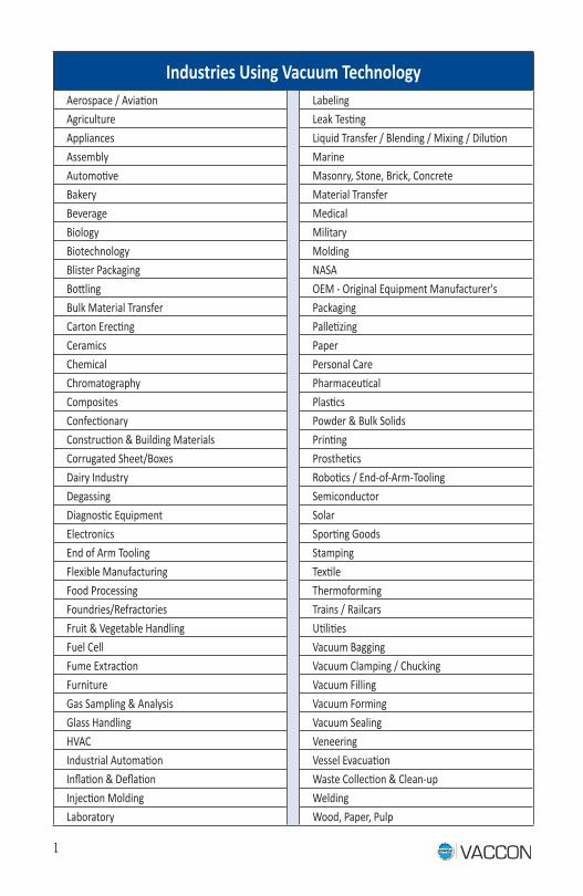
Industries Using Vacuum TechnologyAerospace / Aviation LabelingAgriculture Leak TestingAppliances Liquid Transfer / Blending / Mixing / DilutionAssembly Marine Automotive Masonry, Stone, Brick, ConcreteBakery Material TransferBeverage MedicalBiology MilitaryBiotechnology MoldingBlister Packaging NASABottling OEM - Original Equipment Manufacturer'sBulk Material Transfer PackagingCarton Erecting PalletizingCeramics PaperChemical Personal CareChromatography PharmaceuticalComposites PlasticsConfectionary Powder & Bulk SolidsConstruction & Building Materials PrintingCorrugated Sheet/Boxes ProstheticsDairy Industry Robotics / End-of-Arm-ToolingDegassing SemiconductorDiagnostic Equipment SolarElectronics Sporting GoodsEnd of Arm Tooling StampingFlexible Manufacturing TextileFood Processing ThermoformingFoundries/Refractories Trains / RailcarsFruit & Vegetable Handling UtilitiesFuel Cell Vacuum BaggingFume Extraction Vacuum Clamping / ChuckingFurniture Vacuum FillingGas Sampling & Analysis Vacuum FormingGlass Handling Vacuum SealingHVAC VeneeringIndustrial Automation Vessel EvacuationInflation & Deflation Waste Collection & Clean-upInjection Molding WeldingLaboratory Wood, Paper, Pulp
2
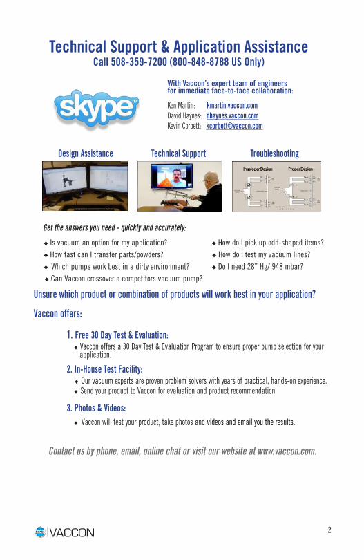
Design Assistance Technical Support Troubleshooting
Get the answers you need - quickly and accurately:
u Is vacuum an option for my application? u How do I pick up odd-shaped items? u How fast can I transfer parts/powders? u How do I test my vacuum lines? u Which pumps work best in a dirty environment? u Do I need 28” Hg/ 948 mbar? u Can Vaccon crossover a competitors vacuum pump?
Unsure which product or combination of products will work best in your application?
Vaccon offers:
1. Free 30 Day Test & Evaluation: u Vaccon offers a 30 Day Test & Evaluation Program to ensure proper pump selection for your application.
2. In-House Test Facility: u Our vacuum experts are proven problem solvers with years of practical, hands-on experience. u Send your product to Vaccon for evaluation and product recommendation.
3. Photos & Videos: u Vaccon will test your product, take photos and videos and email you the results.
Contact us by phone, email, online chat or visit our website at www.vaccon.com.
Ken Martin: kmartin.vaccon.com David Haynes: dhaynes.vaccon.com Kevin Corbett: [email protected]
Technical Support & Application AssistanceCall 508-359-7200 (800-848-8788 US Only)
With Vaccon’s expert team of engineers for immediate face-to-face collaboration:
3
Terms & DefinitionsAir Consumption - The volume of air required to power the vacuum pump. Air consumption is dependent upon the air pressure and the diameter of the orifice through which it flows. Air consumption is based on individual pump Ex.: 1 pump uses 4.8 SCFM 5 pumps use 24 SCFM
Atmospheric Pressure - The atmosphere that surrounds the earth can be considered a reservoir of low pressure air. It’s weight exerts a pressure that varies with temperature, humidity and altitude.
Barometer - A device, usually filled with mercury, that measures atmospheric pressure.
Standard Atmospheric Pressure At Sea Level - 1 ATM = 14.7 PSI = 29.92”Hg = 760mm Hg = 1 Bar
Vacuum Flow - The volume of free air induced by the vacuum pump per unit of time (l/m or SCFM).
Vacuum Force - Force equals the vacuum level times the area of the vacuum surface, i.e., the holding area of a vacuum cup.
Example: Lbs. of Force = (vacuum level in “Hg/2) x Area where 1 PSI = 2“Hg
Vacuum Level - The magnitude of suction created by vacuum pump. The unit of measure is typically “Hg. or mm Hg.
Venturi’s/Ejectors - Air powered vacuum pump.
SCFM - SCFM means Standard Cubic Feet per Minute. “Standard” is air at sea level and at 70o F.
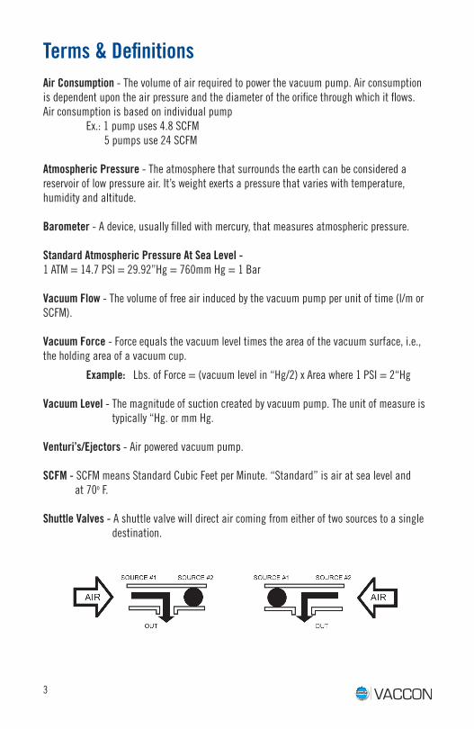
Shuttle Valves - A shuttle valve will direct air coming from either of two sources to a single destination.
4
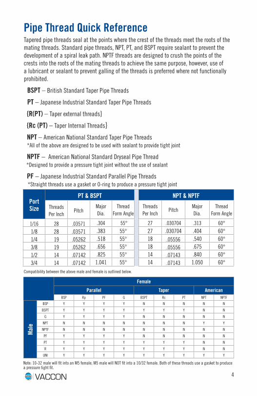
Pipe Thread Quick ReferenceTapered pipe threads seal at the points where the crest of the threads meet the roots of the mating threads. Standard pipe threads, NPT, PT, and BSPT require sealant to prevent the development of a spiral leak path. NPTF threads are designed to crush the points of the crests into the roots of the mating threads to achieve the same purpose, however, use of a lubricant or sealant to prevent galling of the threads is preferred where not functionally prohibited.
BSPT – British Standard Taper Pipe Threads
PT – Japanese Industrial Standard Taper Pipe Threads
{R(PT) – Taper external threads}
{Rc (PT) – Taper Internal Threads}
NPT – American National Standard Taper Pipe Threads *All of the above are designed to be used with sealant to provide tight joint
NPTF – American National Standard Dryseal Pipe Thread *Designed to provide a pressure tight joint without the use of sealant
PF – Japanese Industrial Standard Parallel Pipe Threads *Straight threads use a gasket or O-ring to produce a pressure tight joint
Port Size
PT & BSPT NPT & NPTF
Threads Per Inch
PitchMajor Dia.
Thread Form Angle
Threads Per Inch
PitchMajorDia.
Thread Form Angle
1/16 28 .03571 .304 55° 27 .030704 .313 60°
1/8 28 .03571 .383 55° 27 .030704 .404 60°
1/4 19 .05262 .518 55° 18 .05556 .540 60°
3/8 19 .05262 .656 55° 18 .05556 .675 60°
1/2 14 .07142 .825 55° 14 .07143 .840 60°
3/4 14 .07142 1.041 55° 14 .07143 1.050 60°
Compatibility between the above male and female is outlined below.
Female
Parallel Taper AmericanBSP Rp PF G BSPT Rc PT NPT NPTF
Mal
e
BSP Y Y Y Y N N N N N
BSPT Y Y Y Y Y Y Y N N
G Y Y Y Y N N N N N
NPT N N N N N N N Y Y
NPTF N N N N N N N N N
PF Y Y Y Y N N N N N
PT Y Y Y Y Y Y Y N N
R Y Y Y Y Y Y Y N N
UNI Y Y Y Y Y Y Y Y Y
Note: 10-32 male will fit into an M5 female; M5 male will NOT fit into a 10/32 female. Both of these threads use a gasket to produce a pressure tight fit.
5
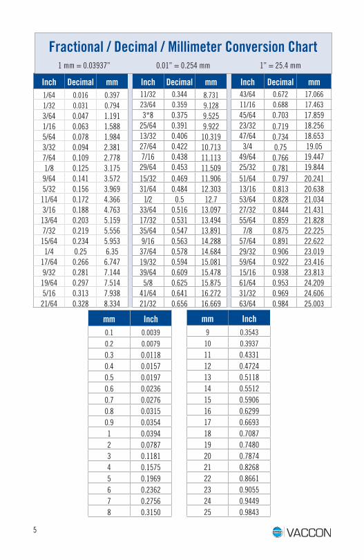
Inch Decimal mm Inch Decimal mm Inch Decimal mm1/64 0.016 0.397 11/32 0.344 8.731 43/64 0.672 17.0661/32 0.031 0.794 23/64 0.359 9.128 11/16 0.688 17.463
3/64 0.047 1.191 3*8 0.375 9.525 45/64 0.703 17.8591/16 0.063 1.588 25/64 0.391 9.922 23/32 0.719 18.2565/64 0.078 1.984 13/32 0.406 10.319 47/64 0.734 18.6533/32 0.094 2.381 27/64 0.422 10.713 3/4 0.75 19.057/64 0.109 2.778 7/16 0.438 11.113 49/64 0.766 19.4471/8 0.125 3.175 29/64 0.453 11.509 25/32 0.781 19.8449/64 0.141 3.572 15/32 0.469 11.906 51/64 0.797 20.2415/32 0.156 3.969 31/64 0.484 12.303 13/16 0.813 20.63811/64 0.172 4.366 1/2 0.5 12.7 53/64 0.828 21.0343/16 0.188 4.763 33/64 0.516 13.097 27/32 0.844 21.43113/64 0.203 5.159 17/32 0.531 13.494 55/64 0.859 21.8287/32 0.219 5.556 35/64 0.547 13.891 7/8 0.875 22.22515/64 0.234 5.953 9/16 0.563 14.288 57/64 0.891 22.6221/4 0.25 6.35 37/64 0.578 14.684 29/32 0.906 23.019
17/64 0.266 6.747 19/32 0.594 15.081 59/64 0.922 23.4169/32 0.281 7.144 39/64 0.609 15.478 15/16 0.938 23.81319/64 0.297 7.514 5/8 0.625 15.875 61/64 0.953 24.2095/16 0.313 7.938 41/64 0.641 16.272 31/32 0.969 24.60621/64 0.328 8.334 21/32 0.656 16.669 63/64 0.984 25.003
mm Inch0.1 0.00390.2 0.0079
0.3 0.01180.4 0.01570.5 0.01970.6 0.02360.7 0.02760.8 0.03150.9 0.03541 0.03942 0.07873 0.11814 0.15755 0.19696 0.23627 0.27568 0.3150
Fractional / Decimal / Millimeter Conversion Chart 1 mm = 0.03937” 0.01” = 0.254 mm 1” = 25.4 mm
mm Inch9 0.354310 0.3937
11 0.433112 0.472413 0.511814 0.551215 0.590616 0.629917 0.669318 0.708719 0.748020 0.787421 0.826822 0.866123 0.905524 0.944925 0.9843
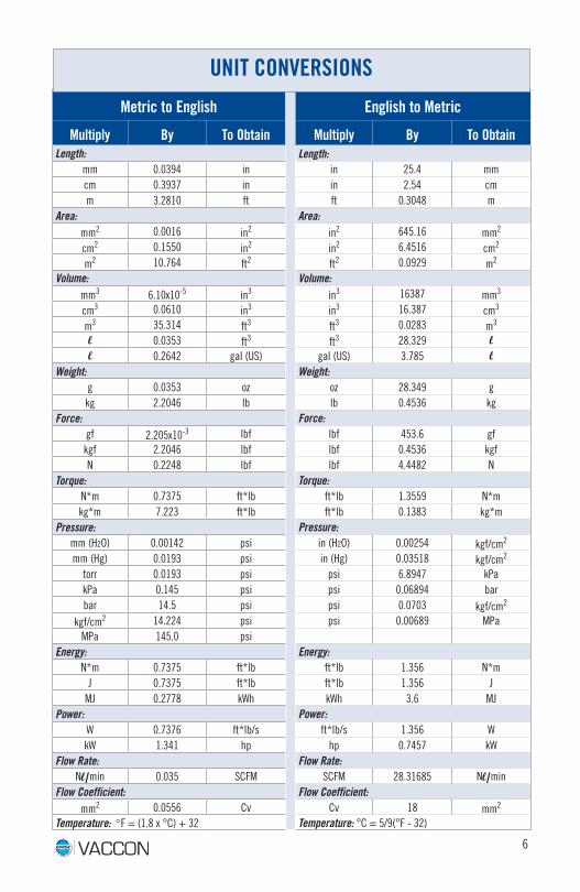
Metric to English English to Metric
Multiply By To Obtain Multiply By To Obtain Length: Length:
mm 0.0394 in in 25.4 mmcm 0.3937 in in 2.54 cmm 3.2810 ft ft 0.3048 m
Area: Area:mm2 0.0016 in2 in2 645.16 mm2
cm2 0.1550 in2 in2 6.4516 cm2
m2 10.764 ft2 ft2 0.0929 m2
Volume: Volume:mm3 6.10x10⁻⁵ in3 in3 16387 mm3
cm3 0.0610 in3 in3 16.387 cm3
m3 35.314 ft3 ft3 0.0283 m3
l 0.0353 ft3 ft3 28.329 ll 0.2642 gal (US) gal (US) 3.785 l
Weight: Weight:g 0.0353 oz oz 28.349 gkg 2.2046 lb lb 0.4536 kg
Force: Force:gf 2.205x10⁻³ lbf lbf 453.6 gfkgf 2.2046 lbf lbf 0.4536 kgfN 0.2248 lbf lbf 4.4482 N
Torque: Torque:N*m 0.7375 ft*lb ft*lb 1.3559 N*mkg*m 7.223 ft*lb ft*lb 0.1383 kg*m
Pressure: Pressure:mm (H2O) 0.00142 psi in (H2O) 0.00254 kgf/cm2
mm (Hg) 0.0193 psi in (Hg) 0.03518 kgf/cm2
torr 0.0193 psi psi 6.8947 kPakPa 0.145 psi psi 0.06894 barbar 14.5 psi psi 0.0703 kgf/cm2
kgf/cm2 14.224 psi psi 0.00689 MPaMPa 145.0 psi
Energy: Energy:N*m 0.7375 ft*lb ft*lb 1.356 N*m
J 0.7375 ft*lb ft*lb 1.356 JMJ 0.2778 kWh kWh 3.6 MJ
Power: Power:W 0.7376 ft*lb/s ft*lb/s 1.356 WkW 1.341 hp hp 0.7457 kW
Flow Rate: Flow Rate:Nl/min 0.035 SCFM SCFM 28.31685 Nl/min
Flow Coefficient: Flow Coefficient:mm2 0.0556 Cv Cv 18 mm2
Temperature: °F = (1.8 x °C) + 32 Temperature: °C = 5/9(°F - 32)
UNIT CONVERSIONS
6
7
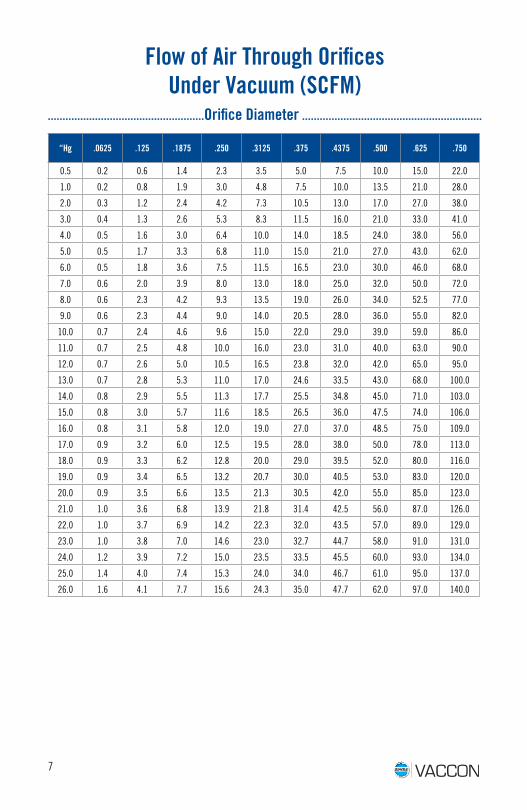
“Hg .0625 .125 .1875 .250 .3125 .375 .4375 .500 .625 .750
0.5 0.2 0.6 1.4 2.3 3.5 5.0 7.5 10.0 15.0 22.0
1.0 0.2 0.8 1.9 3.0 4.8 7.5 10.0 13.5 21.0 28.0
2.0 0.3 1.2 2.4 4.2 7.3 10.5 13.0 17.0 27.0 38.0
3.0 0.4 1.3 2.6 5.3 8.3 11.5 16.0 21.0 33.0 41.0
4.0 0.5 1.6 3.0 6.4 10.0 14.0 18.5 24.0 38.0 56.0
5.0 0.5 1.7 3.3 6.8 11.0 15.0 21.0 27.0 43.0 62.0
6.0 0.5 1.8 3.6 7.5 11.5 16.5 23.0 30.0 46.0 68.0
7.0 0.6 2.0 3.9 8.0 13.0 18.0 25.0 32.0 50.0 72.0
8.0 0.6 2.3 4.2 9.3 13.5 19.0 26.0 34.0 52.5 77.0
9.0 0.6 2.3 4.4 9.0 14.0 20.5 28.0 36.0 55.0 82.0
10.0 0.7 2.4 4.6 9.6 15.0 22.0 29.0 39.0 59.0 86.0
11.0 0.7 2.5 4.8 10.0 16.0 23.0 31.0 40.0 63.0 90.0
12.0 0.7 2.6 5.0 10.5 16.5 23.8 32.0 42.0 65.0 95.0
13.0 0.7 2.8 5.3 11.0 17.0 24.6 33.5 43.0 68.0 100.0
14.0 0.8 2.9 5.5 11.3 17.7 25.5 34.8 45.0 71.0 103.0
15.0 0.8 3.0 5.7 11.6 18.5 26.5 36.0 47.5 74.0 106.0
16.0 0.8 3.1 5.8 12.0 19.0 27.0 37.0 48.5 75.0 109.0
17.0 0.9 3.2 6.0 12.5 19.5 28.0 38.0 50.0 78.0 113.0
18.0 0.9 3.3 6.2 12.8 20.0 29.0 39.5 52.0 80.0 116.0
19.0 0.9 3.4 6.5 13.2 20.7 30.0 40.5 53.0 83.0 120.0
20.0 0.9 3.5 6.6 13.5 21.3 30.5 42.0 55.0 85.0 123.0
21.0 1.0 3.6 6.8 13.9 21.8 31.4 42.5 56.0 87.0 126.0
22.0 1.0 3.7 6.9 14.2 22.3 32.0 43.5 57.0 89.0 129.0
23.0 1.0 3.8 7.0 14.6 23.0 32.7 44.7 58.0 91.0 131.0
24.0 1.2 3.9 7.2 15.0 23.5 33.5 45.5 60.0 93.0 134.0
25.0 1.4 4.0 7.4 15.3 24.0 34.0 46.7 61.0 95.0 137.0
26.0 1.6 4.1 7.7 15.6 24.3 35.0 47.7 62.0 97.0 140.0
Flow of Air Through OrificesUnder Vacuum (SCFM)
.....................................................Orifice Diameter .............................................................
8
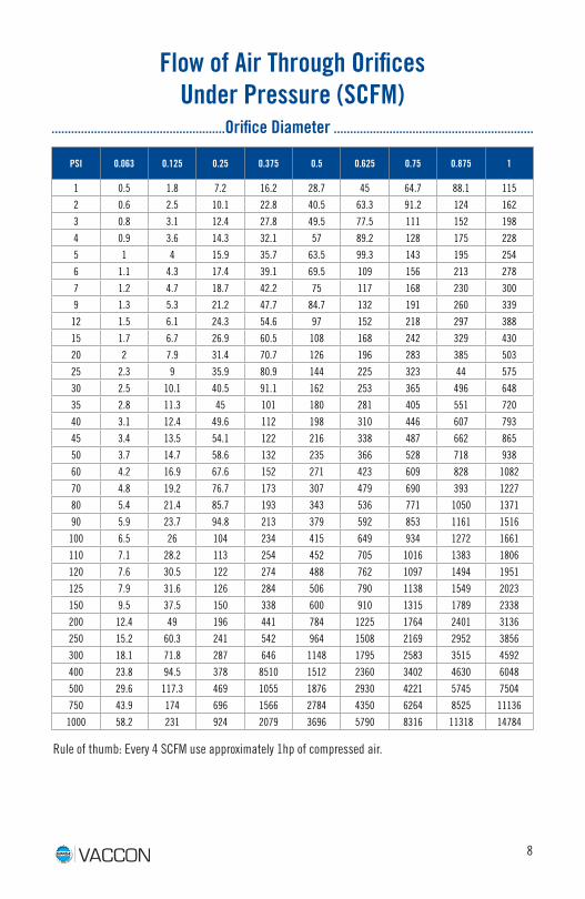
Flow of Air Through OrificesUnder Pressure (SCFM)
.....................................................Orifice Diameter .............................................................
PSI 0.063 0.125 0.25 0.375 0.5 0.625 0.75 0.875 1
1 0.5 1.8 7.2 16.2 28.7 45 64.7 88.1 115
2 0.6 2.5 10.1 22.8 40.5 63.3 91.2 124 162
3 0.8 3.1 12.4 27.8 49.5 77.5 111 152 198
4 0.9 3.6 14.3 32.1 57 89.2 128 175 228
5 1 4 15.9 35.7 63.5 99.3 143 195 254
6 1.1 4.3 17.4 39.1 69.5 109 156 213 278
7 1.2 4.7 18.7 42.2 75 117 168 230 300
9 1.3 5.3 21.2 47.7 84.7 132 191 260 339
12 1.5 6.1 24.3 54.6 97 152 218 297 388
15 1.7 6.7 26.9 60.5 108 168 242 329 430
20 2 7.9 31.4 70.7 126 196 283 385 503
25 2.3 9 35.9 80.9 144 225 323 44 575
30 2.5 10.1 40.5 91.1 162 253 365 496 648
35 2.8 11.3 45 101 180 281 405 551 720
40 3.1 12.4 49.6 112 198 310 446 607 793
45 3.4 13.5 54.1 122 216 338 487 662 865
50 3.7 14.7 58.6 132 235 366 528 718 938
60 4.2 16.9 67.6 152 271 423 609 828 1082
70 4.8 19.2 76.7 173 307 479 690 393 1227
80 5.4 21.4 85.7 193 343 536 771 1050 1371
90 5.9 23.7 94.8 213 379 592 853 1161 1516
100 6.5 26 104 234 415 649 934 1272 1661
110 7.1 28.2 113 254 452 705 1016 1383 1806
120 7.6 30.5 122 274 488 762 1097 1494 1951
125 7.9 31.6 126 284 506 790 1138 1549 2023
150 9.5 37.5 150 338 600 910 1315 1789 2338
200 12.4 49 196 441 784 1225 1764 2401 3136
250 15.2 60.3 241 542 964 1508 2169 2952 3856
300 18.1 71.8 287 646 1148 1795 2583 3515 4592
400 23.8 94.5 378 8510 1512 2360 3402 4630 6048
500 29.6 117.3 469 1055 1876 2930 4221 5745 7504
750 43.9 174 696 1566 2784 4350 6264 8525 11136
1000 58.2 231 924 2079 3696 5790 8316 11318 14784
Rule of thumb: Every 4 SCFM use approximately 1hp of compressed air.
9
Understanding Vacuum TechnologyVacuum technology is one of the most misunderstood, underused; yet, cost effective power sources in automation industries. Selecting the right vacuum pump and suction cups for each application is the key to economic and efficient system design.
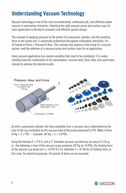
The concept of applying pressure to the piston of a pneumatic cylinder, and the resulting force at the piston rod, is universally understood throughout automation industries. It’s all based on Force = Pressure X Area. This concept also applies to the sizing of a vacuum system, and the selection of a vacuum pump and suction cups for an application.
Every vacuum application has similar variables that need to be considered. It is under-standing how the combination of air consumption, vacuum level, force, flow, and cycle times interact to achieve the desired results.
As with a pneumatic cylinder, the force available from a vacuum cup is determined by the area of the cup multiplied by the vacuum level of the pump expressed in PSI. (Note: Inches of Hg ÷ 2 = PSI -- Example: 28”Hg ÷ 2 = 14 PSI).
Using the formula F = P X A, and a 2” diameter vacuum cup that has an area of 3.14 sq. in., the following is true: If the vacuum pump produces 28”Hg (or 14 PSI), the holding force of the vacuum cup would be F = 14 PSI X 3.14, therefore F = 43.96 lbs of holding force. In this case, for practical purposes, 44 pounds of force can be assumed.
Pressure, Area, and ForceForce = Pressure x Area
= 5.5 BAR x 19.6= 107 kg
F
Piston diameter = 5 cmPiston area = 19.6 2
Air Pressure = 5.5 BAR
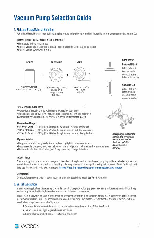
Vacuum Pump Selection Guide
1. Pick and Place/Material Handling:Pick & Place/Material Handling refers to lifting, gripping, rotating and positioning of an object through the use of a vacuum pump with a Vacuum Cup.
Use the Equation: Force = Pressure X Area to determine:• Lifting capacity of the pump and cup • Required vacuum area, i.e. diameter of the cup – see cup section for a more detailed explanation • Required vacuum level of vacuum pump
Force = Pressure x Area where:F = the weight of the objects in lbs [kg] multiplied by the safety factor above P = the expected vacuum level in PSI [Kpa], remember to convert “Hg to PSI by dividing by 2 A = the area of the Vacuum Cup measured in square inches. Use the equation A = pd2
3 Vacuum Level Ranges: • “L” or “F” Series 0-10”Hg, [0 to 339mbar] for low vacuum / high flow applications • “M” or “D” Series 0-20”Hg, [0 to 677mbar] for medium vacuum / high flow applications • “H” or “S” Series 0-28”Hg, [0 to 948mbar] for high vacuum / standard flow applications
3 Types of Material:• Non-porous materials: steel, glass laminated chipboard, rigid plastic, semiconductors, etc. • Porous materials: corrugated, wood, foam, felt, woven materials, objects with extremely rough or uneven surfaces • Flexible materials: plastic films, baked good, IV bags, paper bags – things that wrinkle
Inexact Science: When handling porous materials such as corrugated or heavy fabric, it may be hard to choose the exact pump required because the leakage rate is not normally known. It is best to run a trial to test the ability of the pump to overcome the leakage. For existing systems, consult Vaccon for the equivalent pump size. For new applications, take advantage of Vaccon’s 30 day Test & Evaluation program to ensure proper pump selection.
System Speed:Cycle rate of the pump/cup system is determined by the evacuation speed of the venturi. See Vessel Evacuation.
2. Vessel Evacuation:In many process applications it is necessary to evacuate a vessel for the purpose of purging gases, leak testing and degassing viscous fluids. It may also be simply the length of tubing between the pump and cup that needs to be evacuated.
Knowing the pump’s evacuation speed will help determine process completion time or the production rate of a pick & place system. To find the speed, use the evacuation charts listed in the performance data for each venturi pump. Note that the charts are based on a volume of one cubic foot or one liter of volume to a given vacuum level in “Hg or mbar.
1. Determine the total volume to be evacuated – vessel and/or vacuum lines (cu. ft.), 1728 cu. in = 1 cu. ft.2. Desired vacuum level Hg [mbar] is determined by customer3. Time to reach vacuum level (seconds) – determined by customer
Safety Factors
FORCE AREA
"d"
OBJECT WEIGHTSAFETY FACTOR * Lbs (Kg)
CONVERT "Hg TO PSI, DIVIDE BY 2 (2Hg" = 1 PSI)
AREA = � * d /42
� = 3.14
PSI (Kpa)in (cm )2 2
X=
PRESSURESafety Factors
Horizontal lift = 2Safety factor of 2 is recommended when cup face is in horizontal position.
Vertical lift = 4Safety factor of 4 is recommended when cup face is in vertical position.
4
Increase safety, reliability and speed by using one pump and one cup at each location. Should one cup fail the others will maintain their grip.
10
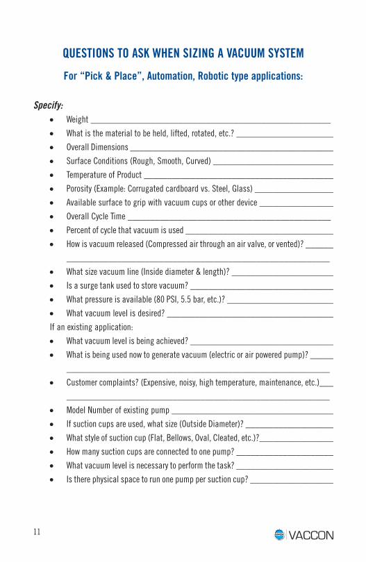
QUESTIONS TO ASK WHEN SIZING A VACUUM SYSTEM
For “Pick & Place”, Automation, Robotic type applications:
Specify:• Weight ____________________________________________________
• What is the material to be held, lifted, rotated, etc.? _____________________
• Overall Dimensions ____________________________________________
• Surface Conditions (Rough, Smooth, Curved) __________________________
• Temperature of Product _________________________________________
• Porosity (Example: Corrugated cardboard vs. Steel, Glass) _________________
• Available surface to grip with vacuum cups or other device ________________
• Overall Cycle Time ____________________________________________
• Percent of cycle that vacuum is used ________________________________
• How is vacuum released (Compressed air through an air valve, or vented)? ______
_________________________________________________________
• What size vacuum line (Inside diameter & length)? ______________________
• Is a surge tank used to store vacuum? _______________________________
• What pressure is available (80 PSI, 5.5 bar, etc.)? _______________________
• What vacuum level is desired? ____________________________________
If an existing application:
• What vacuum level is being achieved? _______________________________
• What is being used now to generate vacuum (electric or air powered pump)? _____
_________________________________________________________
• Customer complaints? (Expensive, noisy, high temperature, maintenance, etc.)___
_________________________________________________________
• Model Number of existing pump ___________________________________
• If suction cups are used, what size (Outside Diameter)? ___________________
• What style of suction cup (Flat, Bellows, Oval, Cleated, etc.)?________________
• How many suction cups are connected to one pump? _____________________
• What vacuum level is necessary to perform the task? _____________________
• Is there physical space to run one pump per suction cup? __________________
11
12
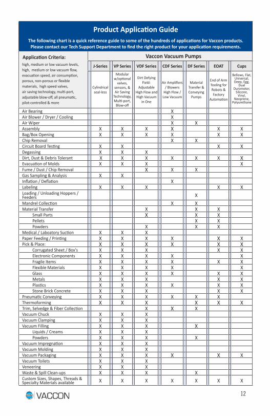
Product Application GuideThe following chart is a quick reference guide to some of the hundreds of applications for Vaccon products.
Please contact our Tech Support Department to find the right product for your application requirements.
Application Criteria: high, medium or low vacuum levels, high, medium or low vacuum flow, evacuation speed, air consumption, porous, non-porous or flexible materials, high speed valves, air saving technology, multi-port, adjustable blow-off, all pneumatic,pilot-controlled & more
Vaccon Vacuum Pumps J-Series VP Series VDF Series CDF Series DF Series EOAT Cups
Cylindrical seal-less
Modular w/optional
valves, sensors, & Air Saving
Technology, Multi-port,
Blow-off
Dirt Defying Field-
Adjustable High Flow and High Vacuum
in One
Air Amplifiers / Blowers
High Flow / Low Vacuum
Material Transfer & Conveying
Pumps
End of Arm Tooling for Robots & Factory
Automation
Bellows, Flat, Universal, Deep, Egg,
Dual Durometer,
Silicone, Vinyl,
Neoprene, Polyurethane
Air Bearing XAir Blower / Dryer / Cooling XAir Wiper X XAssembly X X X X X XBag/Box Opening X X X X X XChip Removal X XCircuit Board Testing X X X XDegassing X X XDirt, Dust & Debris Tolerant X X X X X X XEvacuation of Molds X X X XFume / Dust / Chip Removal X X XGas Sampling & Analysis X XInflation / Deflation XLabeling X X X X XLoading / Unloading Hoppers / Feeders XMandrel Collection X XMaterial Transfer X X X Small Parts X X X Pellets X X Powders X X XMedical / Laboatory Suction X X XPaper Feeding / Printing X X X X X XPick & Place: X X X X X X Corrugated Sheet / Box's X X X X X Electronic Components X X X X X Fragile Items X X X X X X Flexible Materials X X X X X Glass X X X X X X Metals X X X X X Plastics X X X X X X Stone Brick Concrete X X X X XPneumatic Conveying X X X X X XThermoforming X X X X X XTrim, Selvedge & Fiber Collection X X XVacuum Chuck X X XVacuum Clamping X X XVacuum Filling X X X X Liquids / Creams X X X Powders X X X XVacuum Impregnation X X XVacuum Molding X X XVacuum Packaging X X X X X XVacuum Toilets X X XVeneering X X XWaste & Spill Clean-ups X X X XCustom Sizes, Shapes, Threads & Specialty Materials available X X X X X X X
13
TROUBLE-SHOOTING“WHAT TO DO WHEN IT DOESN’T WORK”
There are times when a Vaccon pump is installed and the user reports that “It didn’t work” or “It doesn’t work anymore”. The following are some common causes that can be addressed by the operator before calling Vaccon.
Check the following:1. Was the pump installed? We have had customers tell us that “It looked so small
……. It couldn’t possibly work”. Therefore, it was never installed. 2. Be sure the supply pressure to the pump is the recommended 80 or 60 PSI. In addition,
measure the pressure just before the pump. Sometimes the pressure line may be feed-ing other pneumatic devices causing pressure drops.
3. Was the input line large enough to deliver the necessary SCFM? Small lines starve the pump.
4. Was the fitting the type that reduced the ID of the input air line? Some compression type fittings severely reduce the ID, thus causing problems as described above.
5. Quick disconnects reduce air flow drastically. Be cautious of their use. (Push-to-Connect recommended.)
6. Is there a restriction in the vacuum cup fixture?7. Is the air line connected to the Air Supply port?8. Is the vacuum line connected to the vacuum port?9. Does the system have leaks? This is very basic and sometimes overlooked. 10. Was a Vaccon recommended muffler used? If performance has deteriorated, one cause
could be that the exhaust muffler is dirty. Other mufflers such as sintered bronze and Porex filters get clogged quickly and may cause back pressure .
11. If the pump doesn’t function at all - examine the interior to confirm clear passage. 12. Measure the vacuum level at the cup, not the pump since this will indicate the true
reading.13. Was the correct/best pump selected in the first place? A. Depending on your applica-
tion, it may take trying several pumps to find the best fit. B. Sometimes competitors products were not specified correctly to start.
14. Vaccon offers drawings, installation instructions, operating instructions and the Master Catalog online. Call 508-359-7200 or email [email protected] for assistance. Assemble as many facts as possible and then call Vaccon for support at: 800-848-8788 (US Only) u 508-359-7200 M-F 8AM - 5PM EST.
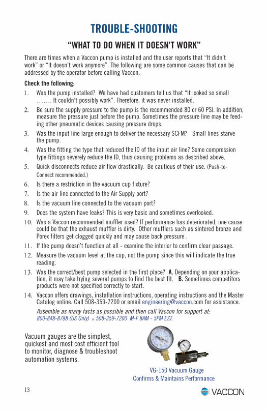
Vacuum gauges are the simplest, quickest and most cost efficient tool to monitor, diagnose & troubleshoot automation systems. VG-150 Vacuum Gauge
Confirms & Maintains Performance
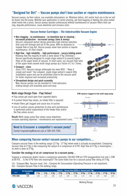
Vacuum pumps, by their nature, use available atmospheric air. Whatever debris, dirt and/or dust are in the air will be drawn into the pump. Whether your application is carton erecting, pet food bagging or feeding die-slick coated sheet metal into a press, Vaccon pumps operate continuously without maintenance or vacuum filters that can clog, degrade performance, cause downtime and increase costs.
Vacuum
Debris
Flap Valves
Flap Valves
Exhaust
Exhaust
Air Supply
Air Supply
Vacuum
Debris
14
Vacuum
Vacuum
Debris
ExhaustAir Supply
RTM replaces clogged in-line multi-stage pump
“Designed for Dirt” – Vaccon pumps don’t lose suction or require maintenance.
• Non-clogging - no maintenance - no downtime due to cleaning - increased production - increased savings (time & money) Vaccon’s advanced venturi design generates high internal velocities that carry dirt through and out of the pump. With no obstacles to impede flow or trap dirt, Vaccon pumps never lose suction or require maintenance. It’s that simple.
• High flow - high reliability - high performance - secure holding power Knowing that the majority of work is done above 9”Hg [305mbar], Vaccon specifically designed its single stage venturi’s to provide higher flows at the upper levels of vacuum. In most cases, our vacuum flow rates at the upper levels exceed multi-stage pumps by a factor of 2 to 7 times.
• Compact - close Since 1972, Vaccon’s design philosophy has been KISS - “Keep it simple and small.” Our compact, single stage venturi’s require little installation space and can be positioned close to the vacuum point for faster response and increased productivity.
• Streamlined design and quick assembly Now, Vaccon pumps can be mounted to T-slot extrusions making design and assembly quick and easy.
Multi-stage Design Flaw - Flap Valves!• Flap valves get stuck open from ingested debris • To protect these flap valves, an intake filter is required• Intake filters get clogged and cause loss of suction• Loss of suction causes production to stop until maintenance
is performed and/or replacement of the intake filter and/or the flap valves occurs
Result: Multi-stage pump flap valves cause downtime, increase operating expenses - maintenance and replacement costs.
Need to Crossover a competitor’s vacuum pump? Contact [email protected] or 508-359-7200.
Vaccon Venturi Cartridges – The Indestructible Vacuum Engine
Model #Air Consumption
SCFM
Imperial – Vacuum Flow (SCFM) vs. Vacuum Level (“Hg)O”Hg 3”Hg 6”Hg 9”Hg 12”Hg 15”Hg 18”Hg 21”Hg 24”Hg 27”Hg 28”Hg
VP80-200H 7.80 5.40 4.70 3.85 3.30 3.00 2.60 2.10 1.60 1.20 0.60 0.00
Working Range
When comparing Vaccon venturi vacuum pumps to our competitors.....Compare vacuum flows in the working range (12”Hg - 27”Hg) where work is actually accomplished. Comparing vacuum flow at 0”Hg is like comparing the output of a compressor at 0 PSI. High flow at 0”Hg is meaningless… no work is done at 0”Hg.
Consider the analogy of an air compressor to a vacuum pump…
Suppose a compressor dealer claims a compressor generates 100,000 CFM at 0 PSI (exaggeration) but only 1 CFM at 80 PSI… Is the 0 PSI flow rate meaningful? The same holds true for a vacuum pump flow rating at 0”Hg.
1st - Compare Max. Vacuum Level, 2nd - Compare Air Consumption (Operating Pressure is not important), 3rd - Compare Vacuum Flow in the working range
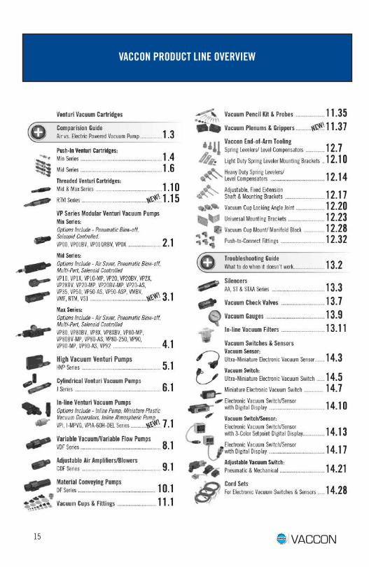
VACCON PRODUCT LINE OVERVIEW
15
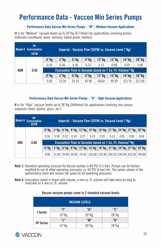
Performance Data - Vaccon Min Series Pumps
Model #Air
ConsumptionSCFM
Imperial – Vacuum Flow (SCFM) vs. Vacuum Level (“Hg)
60H 0.80
O“Hg 3“Hg 6“Hg 9“Hg 12“Hg 15“Hg 18“Hg 21“Hg 24“Hg 27“Hg 28“Hg
0.50 0.38 0.32 0.30 0.27 0.23 0.20 0.13 0.05 0.02 0.00
Evacuation Time in Seconds based on 1 Cu. Ft. Volume/”HgO“Hg 3“Hg 6“Hg 9“Hg 12“Hg 15“Hg 18“Hg 21“Hg 24“Hg 27“Hg 28“Hg
0.00 15.00 29.80 50.60 74.50 102.80 135.90 182.20 245.90 410.20 790.80
Performance Data Vaccon Min Series Pumps - “H” - High Vacuum Applications
Note 1: Standard operating pressure for Vaccon pumps is 80 PSI [5.5 bar]. Pumps can be factory modified to run at other operating pressures i.e. 60 PSI [4 bar] etc. The values shown in the performance chart will remain the same for all operating pressures.
Note 2: Evacuation speed is linear with volume, a two cu. ft. volume will take twice as long to evacuate as a one cu. ft. volume.
Vaccon vacuum pumps come in 3 standard vacuum levels:
Model # Air
ConsumptionSCFM
Imperial - Vacuum Flow (SCFM) vs. Vacuum Level (“Hg)
60M 0.50
0”Hg 3”Hg 6”Hg 9”Hg 12”Hg 15”Hg 18”Hg 20”Hg0.50 0.40 0.30 0.22 0.15 0.08 0.03 0.00
Evacuation Time in Seconds based on 1 Cu. Ft. Volume/”Hg0”Hg 3”Hg 6”Hg 9”Hg 12”Hg 15”Hg 18”Hg 20”Hg0.00 12.50 25.10 43.90 68.60 99.30 153.70 227.00
Performance Data Vaccon Min Series Pumps - “M” - Medium Vacuum Applications
M is for “Medium” vacuum levels up to 20”Hg [677mbar] for applications involving porous materials (cardboard, wood, masonry, baked goods, textiles).
H is for “High” vacuum levels up to 28”Hg [948mbar] for applications involving non-porous materials (steel, plastic, glass, etc.)
16
VACUUM LEVELS
J Series“F” “D” “S”
10”Hg 20”Hg 28”Hg
VP Series“L” “M” “H”
10”Hg 20”Hg 28”Hg
Model #Air
ConsumptionSCFM
Imperial – Vacuum Flow (SCFM) vs. Vacuum Level (“Hg) @ 80 psi
O”Hg 3”Hg 6”Hg 9”Hg 12”Hg 15”Hg 18”Hg 20”Hg
60M 0.50 0.50 0.40 0.30 0.22 0.15 0.08 0.03 0.00
90M 1.40 1.40 1.25 1.20 1.05 0.85 0.65 0.25 0.00
100M 1.80 2.10 2.00 185 1.75 1.60 1.25 0.80 0.00
150M 2.80 3.50 3.20 2.95 2.75 2.50 1.80 0.95 0.00
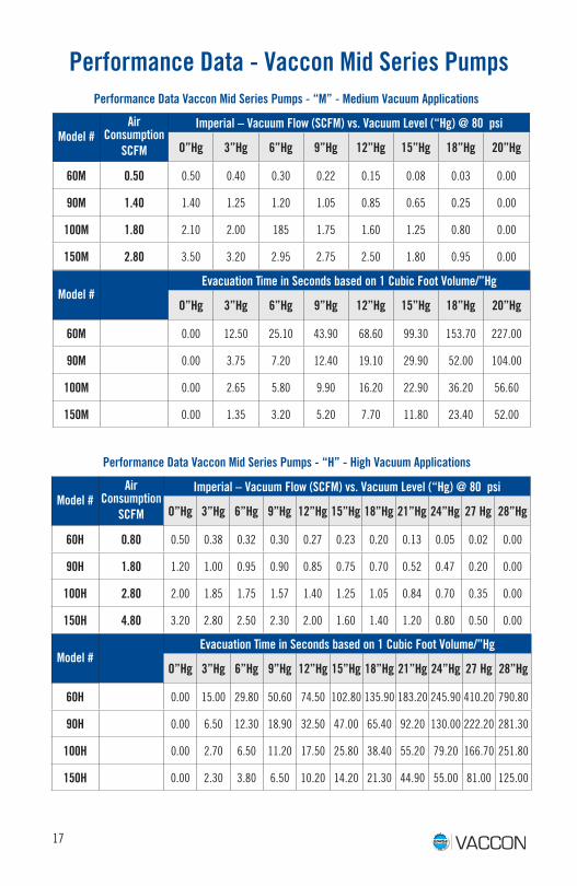
Performance Data - Vaccon Mid Series Pumps
Model #Air
ConsumptionSCFM
Imperial – Vacuum Flow (SCFM) vs. Vacuum Level (“Hg) @ 80 psi
O”Hg 3”Hg 6”Hg 9”Hg 12”Hg 15”Hg 18”Hg 21”Hg 24”Hg 27 Hg 28”Hg
60H 0.80 0.50 0.38 0.32 0.30 0.27 0.23 0.20 0.13 0.05 0.02 0.00
90H 1.80 1.20 1.00 0.95 0.90 0.85 0.75 0.70 0.52 0.47 0.20 0.00
100H 2.80 2.00 1.85 1.75 1.57 1.40 1.25 1.05 0.84 0.70 0.35 0.00
150H 4.80 3.20 2.80 2.50 2.30 2.00 1.60 1.40 1.20 0.80 0.50 0.00
17
Performance Data Vaccon Mid Series Pumps - “M” - Medium Vacuum Applications
Performance Data Vaccon Mid Series Pumps - “H” - High Vacuum Applications
Model #Evacuation Time in Seconds based on 1 Cubic Foot Volume/”Hg
O”Hg 3”Hg 6”Hg 9”Hg 12”Hg 15”Hg 18”Hg 20”Hg
60M 0.00 12.50 25.10 43.90 68.60 99.30 153.70 227.00
90M 0.00 3.75 7.20 12.40 19.10 29.90 52.00 104.00
100M 0.00 2.65 5.80 9.90 16.20 22.90 36.20 56.60
150M 0.00 1.35 3.20 5.20 7.70 11.80 23.40 52.00
Model #Evacuation Time in Seconds based on 1 Cubic Foot Volume/”Hg
O”Hg 3”Hg 6”Hg 9”Hg 12”Hg 15”Hg 18”Hg 21”Hg 24”Hg 27 Hg 28”Hg
60H 0.00 15.00 29.80 50.60 74.50 102.80 135.90 183.20 245.90 410.20 790.80
90H 0.00 6.50 12.30 18.90 32.50 47.00 65.40 92.20 130.00 222.20 281.30
100H 0.00 2.70 6.50 11.20 17.50 25.80 38.40 55.20 79.20 166.70 251.80
150H 0.00 2.30 3.80 6.50 10.20 14.20 21.30 44.90 55.00 81.00 125.00
18
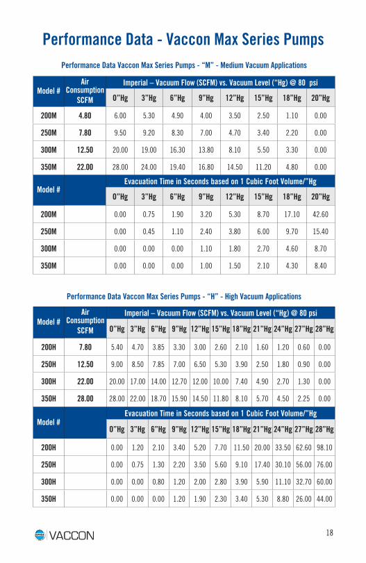
Model #Air
ConsumptionSCFM
Imperial – Vacuum Flow (SCFM) vs. Vacuum Level (“Hg) @ 80 psi
O”Hg 3”Hg 6”Hg 9”Hg 12”Hg 15”Hg 18”Hg 20”Hg
200M 4.80 6.00 5.30 4.90 4.00 3.50 2.50 1.10 0.00
250M 7.80 9.50 9.20 8.30 7.00 4.70 3.40 2.20 0.00
300M 12.50 20.00 19.00 16.30 13.80 8.10 5.50 3.30 0.00
350M 22.00 28.00 24.00 19.40 16.80 14.50 11.20 4.80 0.00
Model #Air
ConsumptionSCFM
Imperial – Vacuum Flow (SCFM) vs. Vacuum Level (“Hg) @ 80 psi
O”Hg 3”Hg 6”Hg 9”Hg 12”Hg 15”Hg 18”Hg 21”Hg 24”Hg 27”Hg 28”Hg
200H 7.80 5.40 4.70 3.85 3.30 3.00 2.60 2.10 1.60 1.20 0.60 0.00
250H 12.50 9.00 8.50 7.85 7.00 6.50 5.30 3.90 2.50 1.80 0.90 0.00
300H 22.00 20.00 17.00 14.00 12.70 12.00 10.00 7.40 4.90 2.70 1.30 0.00
350H 28.00 28.00 22.00 18.70 15.90 14.50 11.80 8.10 5.70 4.50 2.25 0.00
Performance Data Vaccon Max Series Pumps - “M” - Medium Vacuum Applications
Performance Data Vaccon Max Series Pumps - “H” - High Vacuum Applications
Model #Evacuation Time in Seconds based on 1 Cubic Foot Volume/”Hg
O”Hg 3”Hg 6”Hg 9”Hg 12”Hg 15”Hg 18”Hg 20”Hg
200M 0.00 0.75 1.90 3.20 5.30 8.70 17.10 42.60
250M 0.00 0.45 1.10 2.40 3.80 6.00 9.70 15.40
300M 0.00 0.00 0.00 1.10 1.80 2.70 4.60 8.70
350M 0.00 0.00 0.00 1.00 1.50 2.10 4.30 8.40
Model #Evacuation Time in Seconds based on 1 Cubic Foot Volume/”Hg
O”Hg 3”Hg 6”Hg 9”Hg 12”Hg 15”Hg 18”Hg 21”Hg 24”Hg 27”Hg 28”Hg
200H 0.00 1.20 2.10 3.40 5.20 7.70 11.50 20.00 33.50 62.60 98.10
250H 0.00 0.75 1.30 2.20 3.50 5.60 9.10 17.40 30.10 56.00 76.00
300H 0.00 0.00 0.80 1.20 2.00 2.80 3.90 5.90 11.10 32.70 60.00
350H 0.00 0.00 0.00 1.20 1.90 2.30 3.40 5.30 8.80 26.00 44.00
Performance Data - Vaccon Max Series Pumps
19
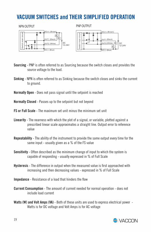
NPN OUTPUT PNP OUTPUT
VACUUM SWITCHES and THEIR SIMPLIFIED OPERATION
Sourcing - PNP is often referred to as Sourcing because the switch closes and provides the source voltage to the load.
Sinking - NPN is often referred to as Sinking because the switch closes and sinks the current to ground.
Normally Open - Does not pass signal until the setpoint is reached
Normally Closed - Passes up to the setpoint but not beyond
FS or Full Scale - The maximum set unit minus the minimum set unit
Linearity - The nearness with which the plot of a signal, or variable, plotted against a prescribed linear scale approximates a straight line. Output error to reference value
Repeatability - The ability of the instrument to provide the same output every time for the same input - usually given as a % of the FS value
Sensitivity - Often described as the minimum change of input to which the system is capable of responding - usually expressed in % of Full Scale
Hysteresis - The difference in output when the measured value is first approached with increasing and then decreasing values - expressed in % of Full Scale
Impedance - Resistance of a load that hinders the flow
Current Consumption - The amount of current needed for normal operation - does not include load current
Watts (W) and Volt Amps (VA) - Both of these units are used to express electrical power - Watts is for DC voltage and Volt Amps is for AC voltage

20
AUTO SWITCHESReed Switches: A thin metal contact is drawn closed by the magnetic field of the piston magnet. Since this is a mechanical switch it will wear out over time and is susceptible to vibration and shock. Their advantage is that they are inexpensive and can be used with AC voltages.
Solid-State Switches: The magnetic field generated by the piston magnet causes a current to flow inside the switch. Since there are no moving parts, the switch life is much longer than a reed switch and they are less prone to vibration and shock. They are more expensive, can only be used with DC voltages and you need to know whether you need a sinking or sourcing switch.
Current Sinking (NPN): The switch sensor “sinks” current from the load through the sensor to ground. The load is connected between positive voltage supply and the output lead of the sensor.
Current Sourcing (PNP): The switch sensor “sources” current through load to ground. The load is connected between the output lead of the sensor and the nega-tive “ground” lead of the supply.
Three wire DC sensors include one wire that provides voltage to the sensor, an output signal wire and a ground wire. Most electro-mechanical loads (relays, counters, solenoids, etc.) can use either a sink or source type switch provided it is wired properly. The proper sensor type must be chosen when used with solid-state load and programmable controllers due to the fact that some of these loads must be grounded.
Wire Colors: Vaccon switch and sensor wire colors conform to European standards.
Positive - BrownNegative - BlueOutput - Black

21
NEMA RATINGS (ELECTRICAL ENCLOSURES)An enclosure is a surrounding case constructed to provide a degree of protection to person-nel against accidental contact with the enclosed equipment and to provide a degree of protection to the enclosed equipment against specified environmental conditions. These are the more common classifications as they pertain to pneumatic components such as valves.
NEMA 1 Intended for indoor use primarily to provide a degree of protection against con-tact with enclosed equipment.
NEMA 2 Intended for indoor use to provide a degree of protection against limited amounts of falling water and dirt.
NEMA 3 Intended for outdoor use to provide a degree of protection against windblown dust, rain, sleet and external ice formation.
NEMA 3R Intended for outdoor use to provide a degree of protection against falling rain, sleet and external ice formation.
NEMA 3S Intended for outdoor use to provide a degree of protection against windblown dust, rain, sleet and priovide for operation of external mechanisms when ice laden.
NEMA 4 Intended for indoor and outdoor use primarily to provide a degree of protection against windblown dust and rain, splashing water and hose directed water.
NEMA 4X Intended for indoor and outdoor use to provide a degree of protection against corrosion, windblown dust and rain, splashing water and hose directed water.
NEMA 6 Intended for indoor and outdoor use primarily to provide a degree of protection against entry of water during occasional submersion to a limited depth.
1st Numeral: Degree of protection with
respect to persons and solid objects
2nd Numeral: Degree of protection with respect to harmful ingress of water
Non
prot
ecte
d
Drip
ping
wat
er
Drip
ping
wat
er
+/- 1
5°
Spra
ying
wat
er
+/- 6
0°
Spla
shin
g wa
ter
360°
Wat
er je
ts
Heav
y se
as
Imm
ersi
on
Subm
ersi
on
Not protected 0 IP00 IP01 IP02
Solid objects > ø50mm 1 IP10 IP11 IP12 IP13
Solid objects > ø12mm 2 IP20 IP21 IP22 IP23
Solid objects > ø2.5mm 3 IP30 IP31 IP32 IP33 IP34
Solid objects > ø1.0mm 4 IP40 IP41 IP42 IP43 IP44 IP45 IP46
Dust protected 5 IP54 IP55 IP56
Dust tight 6 IP65 IP66 IP67 IP68
IP Ratings (Electrical Enclosures)

22
COMPARISON CHART FOR ELECTRONIC SWITCHES/ SENSORS
Model # Display Type
Setpoint Mechanism
Hysteresis Adjustment
# and Type of Outputs
Operating Range
Quick Disconnect
VTMV-QD-6 N/A N/A N/A 1 1-5VDC 0 ~ 29.9”Hg (0 ~ -101.3kPa)
M8-3 on 6” pigtail
VSMN-QD-6 LED Trimmer NONE 1 NPN 0 ~ 29.9”Hg
(0 ~ -101.3kPa)M8-3 on 6”
pigtail
VSMP-QD-6 LED Trimmer NONE 1 PNP 0 ~ 29.9”Hg
(0 ~ -101.3kPa)M8-3 on 6”
pigtail
VXXN-QD-6 LED Trimmer YES 1 NPN0 ~ 29.9”Hg
(0 ~ -101.3kPa)M8-3 on
6” pigtail
VXXP-QD-6 LED Trimmer YES 1 PNP0 ~ 29.9”Hg
(0 ~ -101.3kPa)M8-3 on
6” pigtail
VDXN-QD-6 3 Digit Digital Programmable YES 2 NPN0 ~ 29.9”Hg
(0 ~ -101.3kPa)M8-4 on
6” pigtail
VDXP-QD-6 3 Digit Digital Programmable YES 2 PNP 0 ~ 29.9”Hg
(0 ~ -101.3kPa)M8-4 on
6” pigtail
VDMN-QD-6 3-color/ 3-section Digital
Programmable YES 2 NPN0 ~ 29.9”Hg
(0 ~ -101.3kPa)M8-4 on
6” pigtail
VDMP-QD-6 3-color/ 3-section Digital
Programmable YES 2 PNP0 ~ 29.9”Hg
(0 ~ -101.3kPa)M8-4 on
6” pigtail
VDSN-QD-6 3-1/2 Digit LED Display
Programmable YES2 NPN & 1 1-5VDC
0 ~ 29.9”Hg (0 ~ -101.3kPa)
M12-5 on 6” pigtail
VDSP-QD-6 3-1/2 Digit LED Display
Programmable YES2 PNP &
1 1-5VDC0 ~ 29.9”Hg
(0 ~ -101.3kPa)M12-5
on 6” pigtail
Vaccon Family of Electronic Switches & Sensors

23
Vaccon End-of-Arm Tooling Poster
To receive a free copy of Vaccon’s End-of-Arm Tooling Poster please email [email protected] or call 508-359-7200.
www.vaccon.com1-800-848-8788 • 508-359-7200
Whether your product changes as it goes through the production process or your production process changes to handle new products – Vaccon pumps, cups, accessories and End-of-Arm Tooling are flexible and versatile to keep your production productive.
Having the right pump for your manufacturing equipment reduces changeover times between products and processes. Vaccon offers an extensive inventory of over 500 dirt tolerant vacuum pumps and accessories to meet your application needs.
With over 40 years of vacuum application and engineering experience, Vaccon appreciates working with creative engineers to design and manufacture efficient, innovative and reliable vacuum automation solutions.
Vacuum PumpsVaccon’s extensive line of venturi vacuum pumps include miniature pumps, optional single or dual controlled solenoid valves, Air Saver pumps (green technology), pneumatic blow-offs, Multi-port pumps, high vacuum pumps, variable vacuum/variable flow vacuum pumps, material conveying vacuum pumps, air amplifiers/blowers, air-piloted vacuum pumps, apple core style mounts, manifolds and more.
AccessoriesOur complete line of accessories include vacuum cups, spring levelers, vacuum cup fittings, silencers, vacuum check valves, filters, vacuum and pressure digital, mechanical and adjustable switches and sensors, vacuum gauges, quick disconnects, ultra mini cups, probes, vacuum pencils and more.
End-of-Arm ToolingIt’s your choice….order a single component or a complete system, Vaccon’s EOAT product line offers light duty and heavy duty spring levelers and brackets, fixed extension shafts and brackets, vacuum cup swivel joints, universal mounting brackets, manifold block/cup mounts, extrusions, push-to-connect fittings and more.
Problems are opportunities that are looking for a solution. We can help.
Custom ProductsAt Vaccon, our entrepreneurial spirit loves a challenge. If it doesn’t defy the laws of physics, (and sometimes even if it does), we’ll try just about anything. We like to think of ourselves as a friend to the OEM - Original Equipment Manufacturers. Custom Products are Standard at Vaccon.
Modified ProductsWhen off-the-shelf doesn’t work, Vaccon engineering, application and manufacturing capabilities can provide unique solutions to your specifications. Whether it’s as simple as modifying a standard product or more complex requiring a new design, shape, performance levels or specialty materials…
Vaccon has the solution!
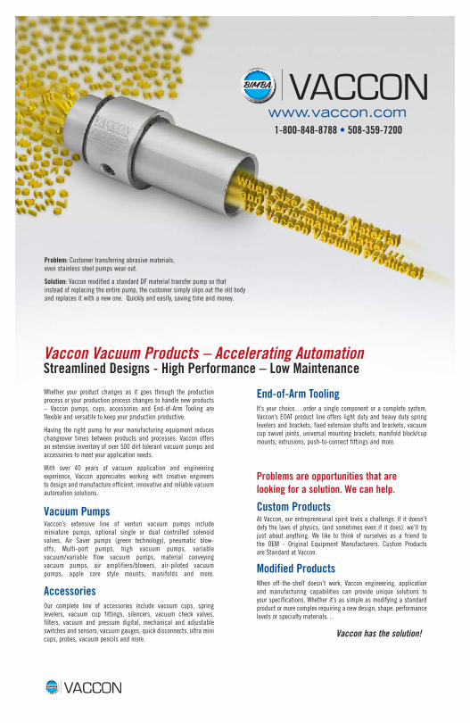
Vaccon Vacuum Products – Accelerating Automation Streamlined Designs - High Performance – Low Maintenance
Problem: Customer transferring abrasive materials, even stainless steel pumps wear out.
Solution: Vaccon modified a standard DF material transfer pump so that instead of replacing the entire pump, the customer simply slips out the old body and replaces it with a new one. Quickly and easily, saving time and money.

www.vaccon.com
Vaccon’s Catalog Comes Alive on www.vaccon.comPowerful new design tool lets you quickly configure the product you need in
the 2D and 3D format of your choice saving valuable design time. Vaccon’s digital catalog offers the visual appeal of our traditional catalog coupled with interactive
possibilities only available online. Access Vaccon’s catalog from anywhere!
Bimba Vaccon9 Industrial Park RoadMedway, MA 02053
Visit us on the web @ www.vaccon.com508-359-7200 • 800-848-8788 (US Only)
Fax: 508-359-0177©2017 Bimba Vaccon
Vaccon Meets Your Global Needs – Contact Our Worldwide Distributor Network
Got Dirt… Get Vaccon!Reliable in conditions that cause others to fail.
Vaccon pumps won’t clog or lose suction.