v3 100 lpm sectional spool valve - group hes · the v3-100 sectional spool valve is one of the most...
TRANSCRIPT
79
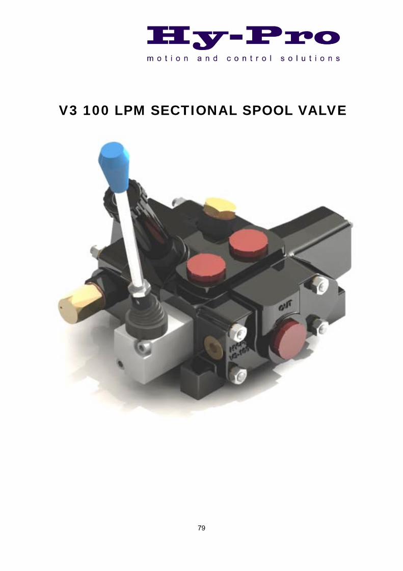
V3 100 LPM SECTIONAL SPOOL VALVE
80
Description The V3-100 sectional spool valve is one of the most compact 100 l/min valve available. Designed for pressures up to 250 bar the valve is available with two, three and four position spool control options and a range of spool types. The lever mechanism is a pressure die casting which totally encloses the spool for added protection. A range of optional ancillary valves are also available to be able to match the requirements of the most complicated and demanding circuits. The V3-100 is also available with solenoid control. It uses powerful yet compact 24 watt DC coils to switch the internal oil pilot to engage the main spool. A damping orifice fitted in the pilot line eliminates the harshness usually associated with standard direct acting solenoid valves and gives a positive feel to the control system. Both manual and solenoid sections can be built into a valve assembly and the solenoid sections have the options of lever override.
Application
Designed to be used in applications requiring a rugged, compact control valve with the option of remote control. Typically in the automotive recovery, recycling and agricultural industries where a mix of manual and solenoid control is essential.
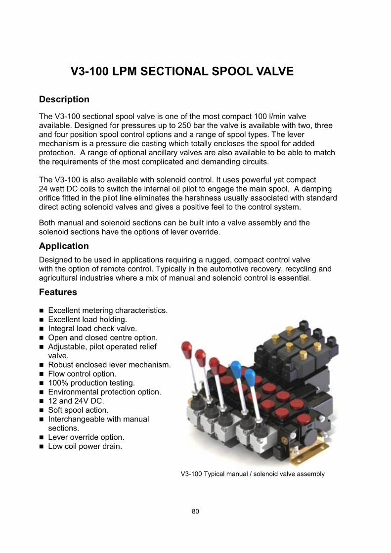
Features Excellent metering characteristics. Excellent load holding. Integral load check valve. Open and closed centre option. Adjustable, pilot operated relief
valve. Robust enclosed lever mechanism. Flow control option. 100% production testing. Environmental protection option. 12 and 24V DC. Soft spool action. Interchangeable with manual
sections. Lever override option. Low coil power drain.
V3-100 LPM SECTIONAL SPOOL VALVE
V3-100 Typical manual / solenoid valve assembly
81
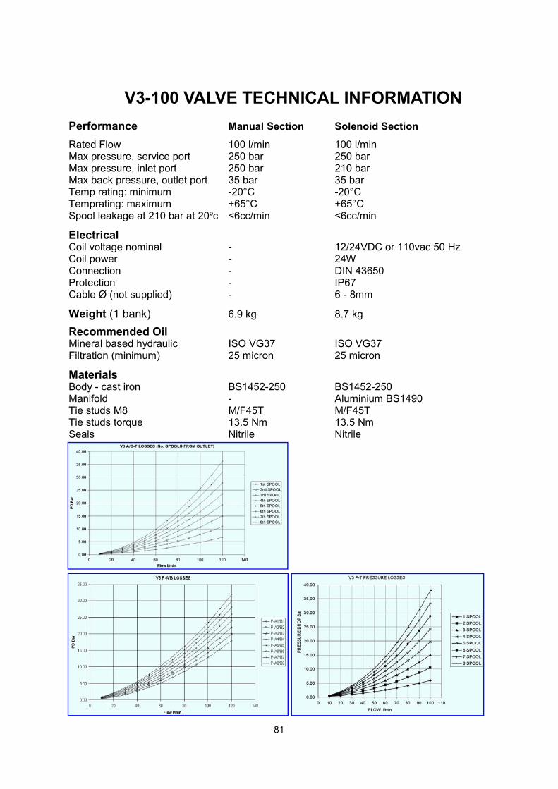
V3-100 VALVE TECHNICAL INFORMATION
Performance Manual Section Solenoid Section
Rated Flow 100 l/min 100 l/min Max pressure, service port 250 bar 250 bar Max pressure, inlet port 250 bar 210 bar Max back pressure, outlet port 35 bar 35 bar Temp rating: minimum -20°C -20°C Temprating: maximum +65°C +65°C Spool leakage at 210 bar at 20ºc <6cc/min <6cc/min
Electrical Coil voltage nominal - 12/24VDC or 110vac 50 Hz Coil power - 24W Connection - DIN 43650 Protection - IP67 Cable Ø (not supplied) - 6 - 8mm
Weight (1 bank) 6.9 kg 8.7 kg
Recommended Oil Mineral based hydraulic ISO VG37 ISO VG37 Filtration (minimum) 25 micron 25 micron
Materials Body - cast iron BS1452-250 BS1452-250 Manifold - Aluminium BS1490 Tie studs M8 M/F45T M/F45T Tie studs torque 13.5 Nm 13.5 Nm Seals Nitrile Nitrile
82
USEDNOT
PIN 2PIN 1
COIL CONNECTIONS
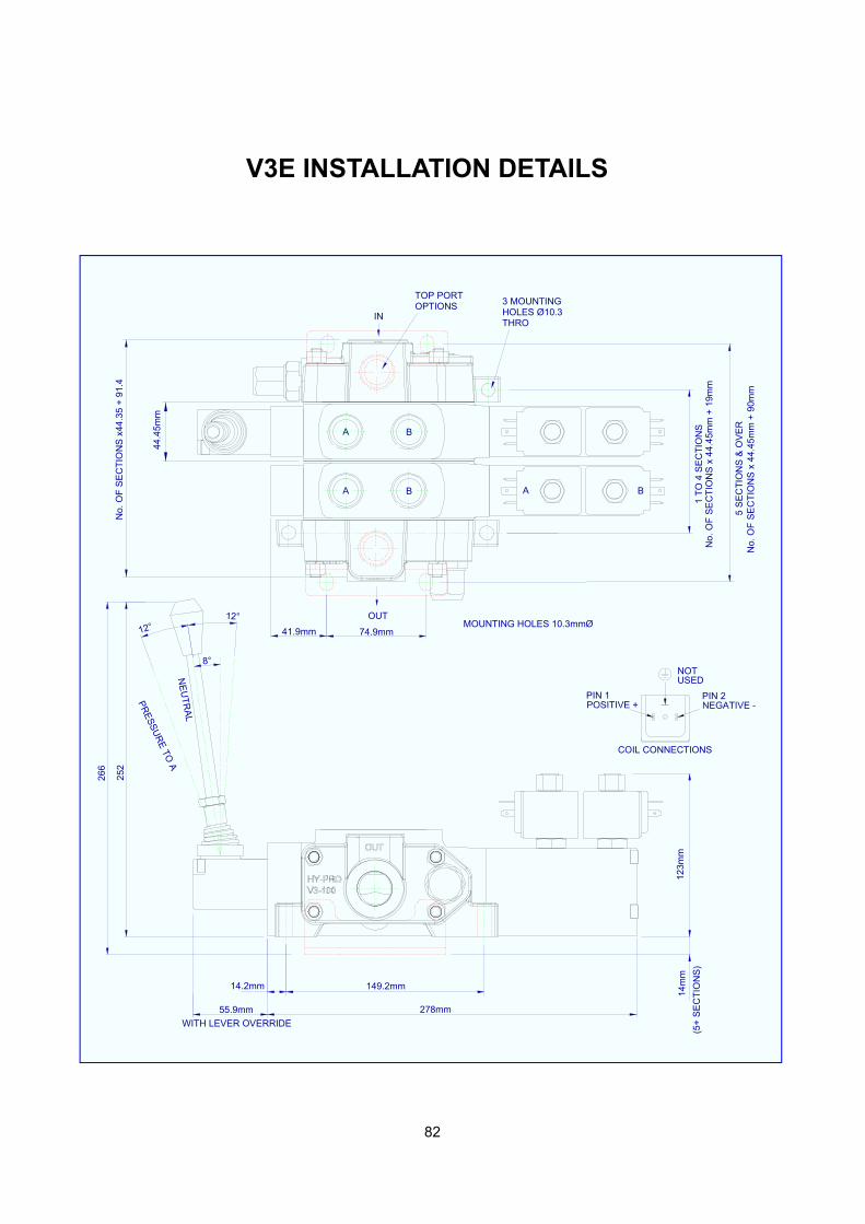
278mm55.9mm
149.2mm
(5+
SE
CT
ION
S)
14m
m12
3mm
MOUNTING HOLES 10.3mmØ
44.4
5mm
1 T
O 4
SE
CT
ION
S
No.
OF
SE
CT
ION
S x
44.
45m
m +
90m
m5
SE
CT
ION
S &
OV
ER
No.
OF
SE
CT
ION
S x
44.
45m
m +
19m
m
A B
12°
8°
12°
PR
ES
SU
RE
TO A
NE
UT
RA
L
266
INTHROHOLES Ø10.33 MOUNTING
OUT
BA
A B
OPTIONSTOP PORT
No.
OF
SE
CT
ION
S x
44.3
5 +
91.
4
WITH LEVER OVERRIDE
74.9mm
14.2mm
41.9mm
252
V3E INSTALLATION DETAILS
83
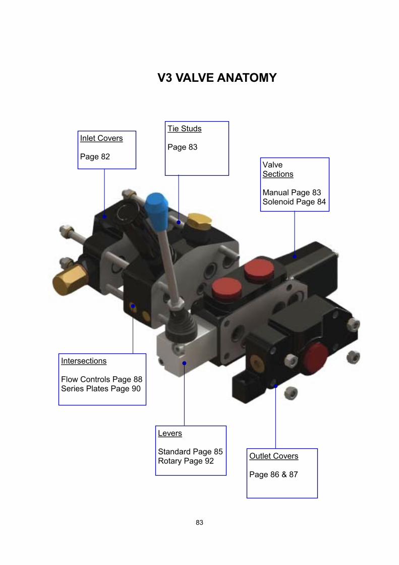
V3 VALVE ANATOMY
Inlet Covers Page 82
Intersections Flow Controls Page 88 Series Plates Page 90
Outlet Covers Page 86 & 87
Tie Studs Page 83
Valve Sections Manual Page 83 Solenoid Page 84
Levers Standard Page 85 Rotary Page 92
84
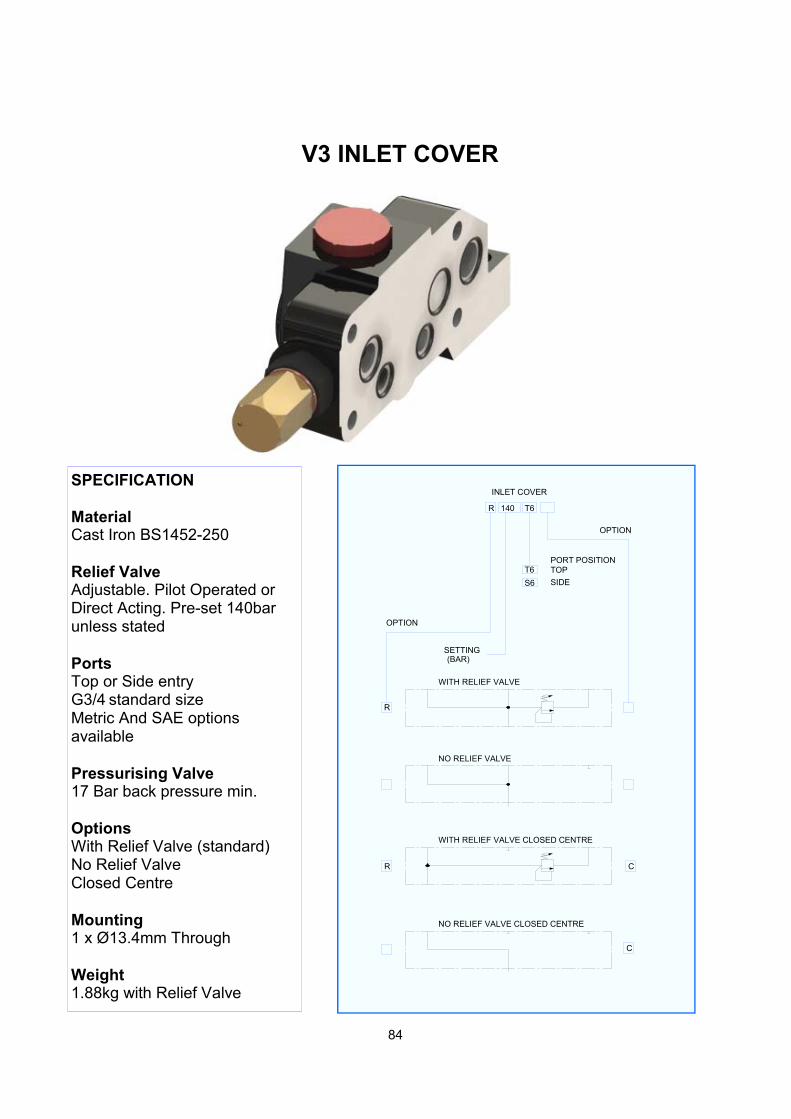
V3 INLET COVER
SPECIFICATION Material Cast Iron BS1452-250 Relief Valve Adjustable. Pilot Operated or Direct Acting. Pre-set 140bar unless stated Ports Top or Side entry G3/4 standard size Metric And SAE options available Pressurising Valve 17 Bar back pressure min. Options With Relief Valve (standard) No Relief Valve Closed Centre Mounting 1 x Ø13.4mm Through Weight 1.88kg with Relief Valve
R 140 T6
INLET COVER
R
C
SETTING(BAR)
T6
S6
PORT POSITIONTOP
SIDE
OPTION
WITH RELIEF VALVE
NO RELIEF VALVE
NO RELIEF VALVE CLOSED CENTRE
WITH RELIEF VALVE CLOSED CENTRE
R C
OPTION
85
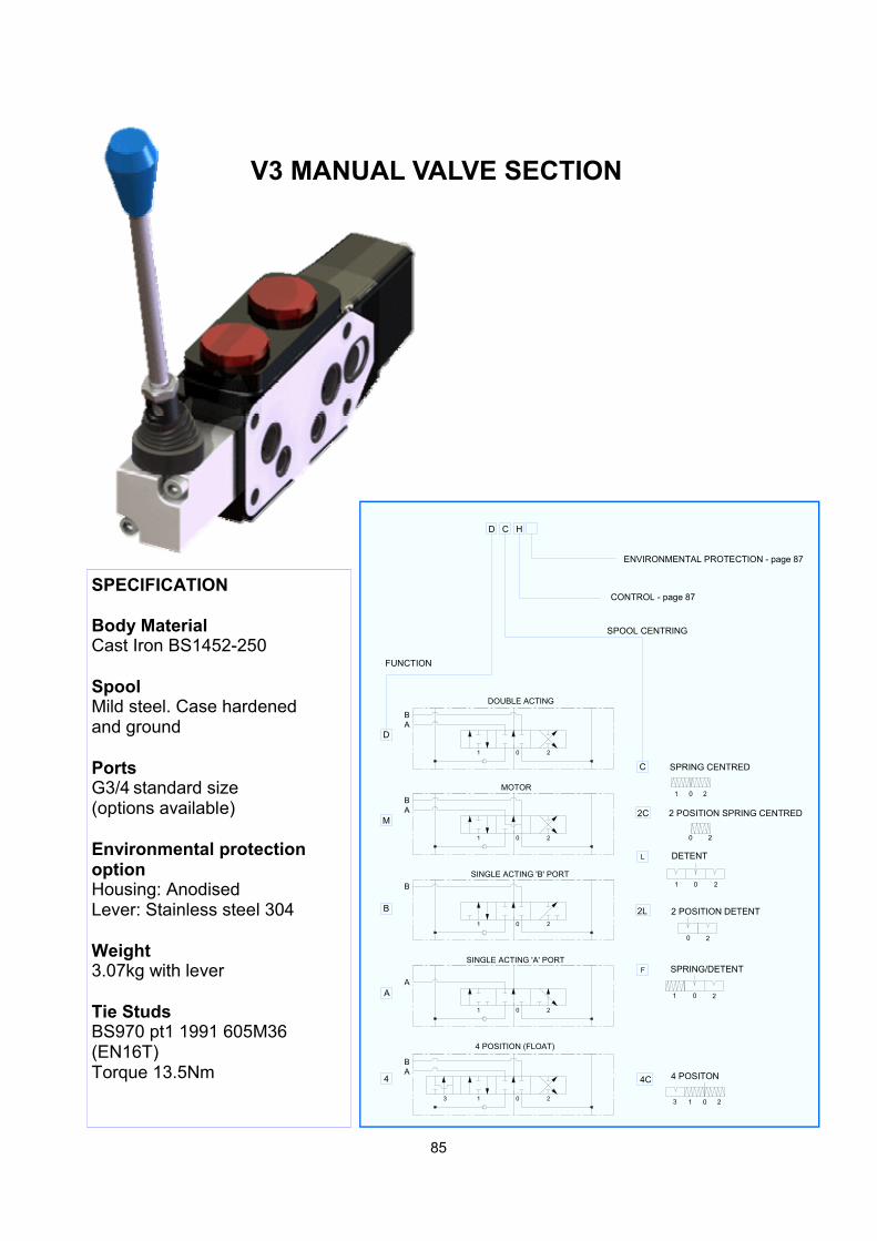
V3 MANUAL VALVE SECTION
SPECIFICATION Body Material Cast Iron BS1452-250 Spool Mild steel. Case hardened and ground Ports G3/4 standard size (options available) Environmental protection option Housing: Anodised Lever: Stainless steel 304 Weight 3.07kg with lever Tie Studs BS970 pt1 1991 605M36 (EN16T) Torque 13.5Nm
CD H
4C
C
2C
F
L
2L
A
B
4
M
D
FUNCTION
SPOOL CENTRING
SPRING CENTRED
2 POSITION SPRING CENTRED
DETENT
2 POSITION DETENT
SPRING/DETENT
4 POSITON
01 2
21 0
0
0
1 0 2
21 03
2
2
01 2
AB
DOUBLE ACTING
BA
MOTOR
SINGLE ACTING 'A' PORT
SINGLE ACTING 'B' PORT
4 POSITION (FLOAT)
21 0
21 0
21 0
21 0
AB
B
A
3
ENVIRONMENTAL PROTECTION - page 87
CONTROL - page 87
86
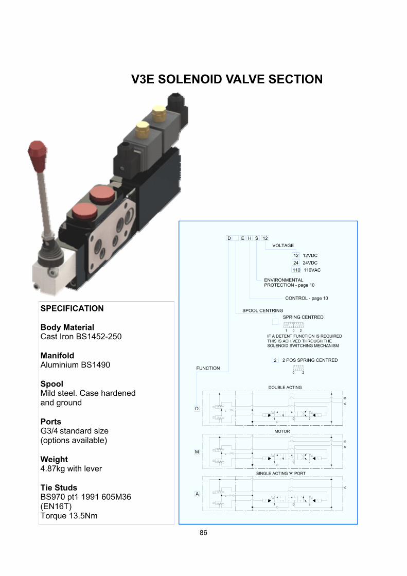
V3E SOLENOID VALVE SECTION
SPECIFICATION Body Material Cast Iron BS1452-250 Manifold Aluminium BS1490 Spool Mild steel. Case hardened and ground Ports G3/4 standard size (options available) Weight 4.87kg with lever Tie Studs BS970 pt1 1991 605M36 (EN16T) Torque 13.5Nm
P
01 2
A
01 2
BA
AB
P
VOLTAGE
110VAC
24VDC
12VDC
110
24
12
12
SOLENOID SWITCHING MECHANISMTHIS IS ACHIVED THROUGH THEIF A DETENT FUNCTION IS REQUIRED
E
CONTROL - page 10
SINGLE ACTING 'A' PORT
MOTOR
DOUBLE ACTING
21 0
20
21 0
2 POS SPRING CENTRED
SPRING CENTRED
SPOOL CENTRING
FUNCTION
D
M
A
2
HD S
ENVIRONMENTALPROTECTION - page 10
P
87
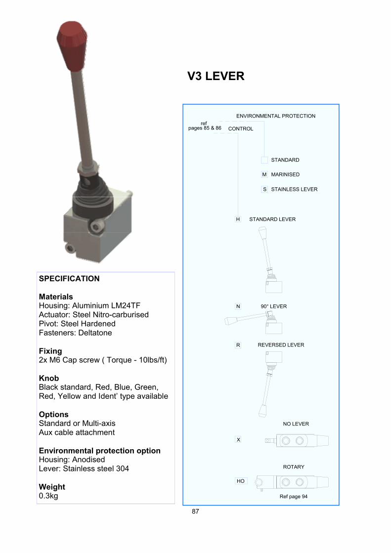
V3 LEVER
SPECIFICATION Materials Housing: Aluminium LM24TF Actuator: Steel Nitro-carburised Pivot: Steel Hardened Fasteners: Deltatone Fixing 2x M6 Cap screw ( Torque - 10lbs/ft) Knob Black standard, Red, Blue, Green, Red, Yellow and Ident’ type available Options Standard or Multi-axis Aux cable attachment Environmental protection option Housing: Anodised Lever: Stainless steel 304 Weight 0.3kg
X
STAINLESS LEVER
MARINISED
STANDARD
S
M
REVERSED LEVER
90° LEVER
STANDARD LEVER
R
N
H
CONTROL
NO LEVER
ENVIRONMENTAL PROTECTION
pages 85 & 86ref
HO
ROTARY
Ref page 94
88
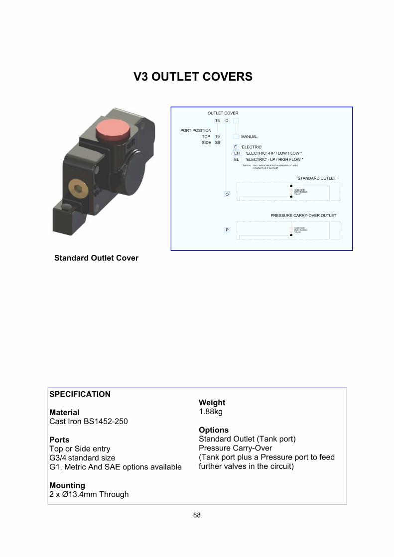
SPECIFICATION Material Cast Iron BS1452-250 Ports Top or Side entry G3/4 standard size G1, Metric And SAE options available Mounting 2 x Ø13.4mm Through
Weight 1.88kg Options Standard Outlet (Tank port) Pressure Carry-Over (Tank port plus a Pressure port to feed further valves in the circuit)
V3 OUTLET COVERS
STANDARD OUTLET
SIDE
TOP
PORT POSITION
S6
T6
'ELECTRIC'
'ELECTRIC' - LP / HIGH FLOW *
'ELECTRIC' -HP / LOW FLOW *
* SPECIAL - ONLY APPLICABLE IN CERTAIN APPLICATIONS
- CONTACT US IF IN DOUBT
E
MANUAL
EH
EL
SOLENOIDRESTRICTORVALVE
VALVERESTRICTORSOLENOID
T6 O
OUTLET COVER
PRESSURE CARRY-OVER OUTLET
P
O
Standard Outlet Cover
89
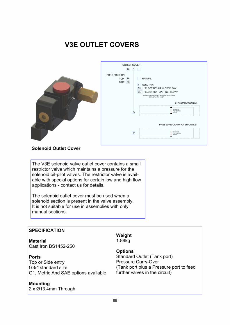
The V3E solenoid valve outlet cover contains a small restrictor valve which maintains a pressure for the solenoid oil-pilot valves. The restrictor valve is avail-able with special options for certain low and high flow applications - contact us for details. The solenoid outlet cover must be used when a solenoid section is present in the valve assembly. It is not suitable for use in assemblies with only manual sections.
Solenoid Outlet Cover
V3E OUTLET COVERS
STANDARD OUTLET
SIDE
TOP
PORT POSITION
S6
T6
'ELECTRIC'
'ELECTRIC' - LP / HIGH FLOW *
'ELECTRIC' -HP / LOW FLOW *
* SPECIAL - ONLY APPLICABLE IN CERTAIN APPLICATIONS
- CONTACT US IF IN DOUBT
E
MANUAL
EH
EL
SOLENOIDRESTRICTORVALVE
VALVERESTRICTORSOLENOID
T6 O
OUTLET COVER
PRESSURE CARRY-OVER OUTLET
P
O
SPECIFICATION Material Cast Iron BS1452-250 Ports Top or Side entry G3/4 standard size G1, Metric And SAE options available Mounting 2 x Ø13.4mm Through
Weight 1.88kg Options Standard Outlet (Tank port) Pressure Carry-Over (Tank port plus a Pressure port to feed further valves in the circuit)
90
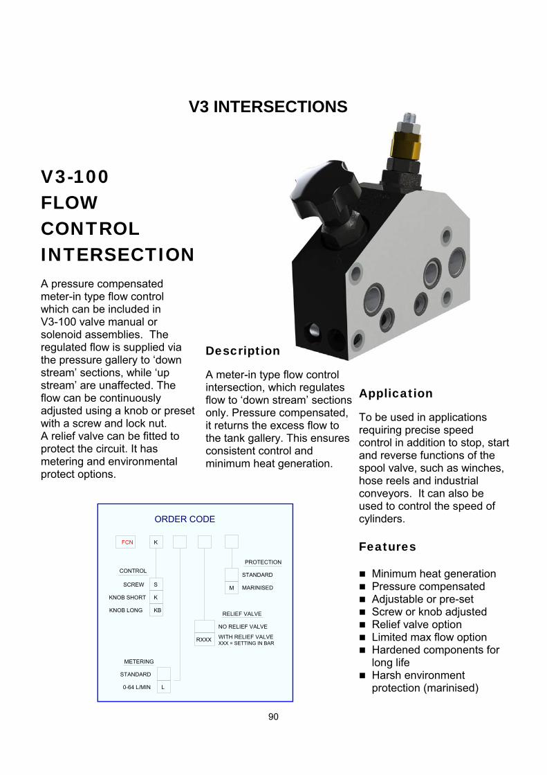
V3 INTERSECTIONS
FCN
CONTROL
KNOB SHORT K
KBKNOB LONG
ORDER CODE
K
STANDARD
MARINISED
PROTECTION
M
0-64 L/MIN
STANDARD
METERING
RELIEF VALVE
NO RELIEF VALVE
WITH RELIEF VALVERXXXXXX = SETTING IN BAR
L
SSCREW
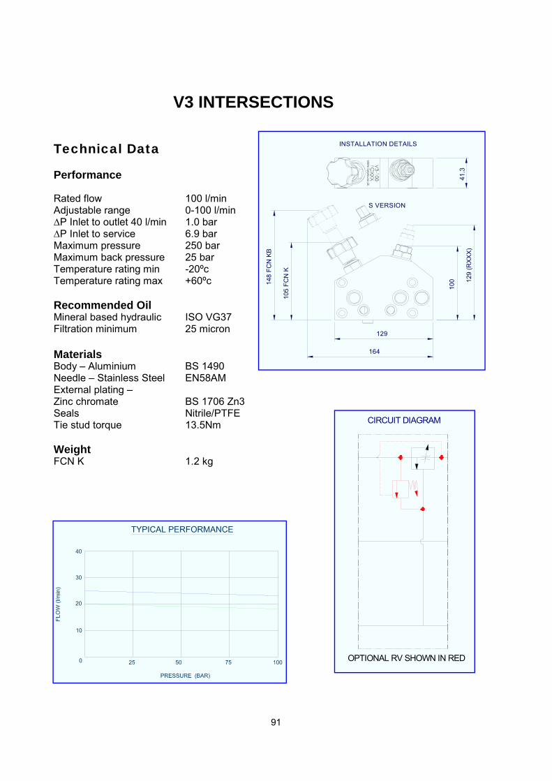
V3-100 FLOW CONTROL INTERSECTION
A pressure compensated meter-in type flow control which can be included in V3-100 valve manual or solenoid assemblies. The regulated flow is supplied via the pressure gallery to ‘down stream’ sections, while ‘up stream’ are unaffected. The flow can be continuously adjusted using a knob or preset with a screw and lock nut. A relief valve can be fitted to protect the circuit. It has metering and environmental protect options.
Description A meter-in type flow control intersection, which regulates flow to ‘down stream’ sections only. Pressure compensated, it returns the excess flow to the tank gallery. This ensures consistent control and minimum heat generation.
Application To be used in applications requiring precise speed control in addition to stop, start and reverse functions of the spool valve, such as winches, hose reels and industrial conveyors. It can also be used to control the speed of cylinders.
Features Minimum heat generation Pressure compensated Adjustable or pre-set Screw or knob adjusted Relief valve option Limited max flow option Hardened components for
long life Harsh environment
protection (marinised)
91
Technical Data
Performance Rated flow 100 l/min Adjustable range 0-100 l/min ∆P Inlet to outlet 40 l/min 1.0 bar ∆P Inlet to service 6.9 bar Maximum pressure 250 bar Maximum back pressure 25 bar Temperature rating min -20ºc Temperature rating max +60ºc Recommended Oil Mineral based hydraulic ISO VG37 Filtration minimum 25 micron Materials Body – Aluminium BS 1490 Needle – Stainless Steel EN58AM External plating – Zinc chromate BS 1706 Zn3 Seals Nitrile/PTFE Tie stud torque 13.5Nm Weight FCN K 1.2 kg
164
129
105
FC
N K
148
FC
N K
B
INSTALLATION DETAILS
S VERSION
100 1
29 (
RX
XX
)
OPTIONAL RV SHOWN IN RED
CIRCUIT DIAGRAM
V3 INTERSECTIONS
92
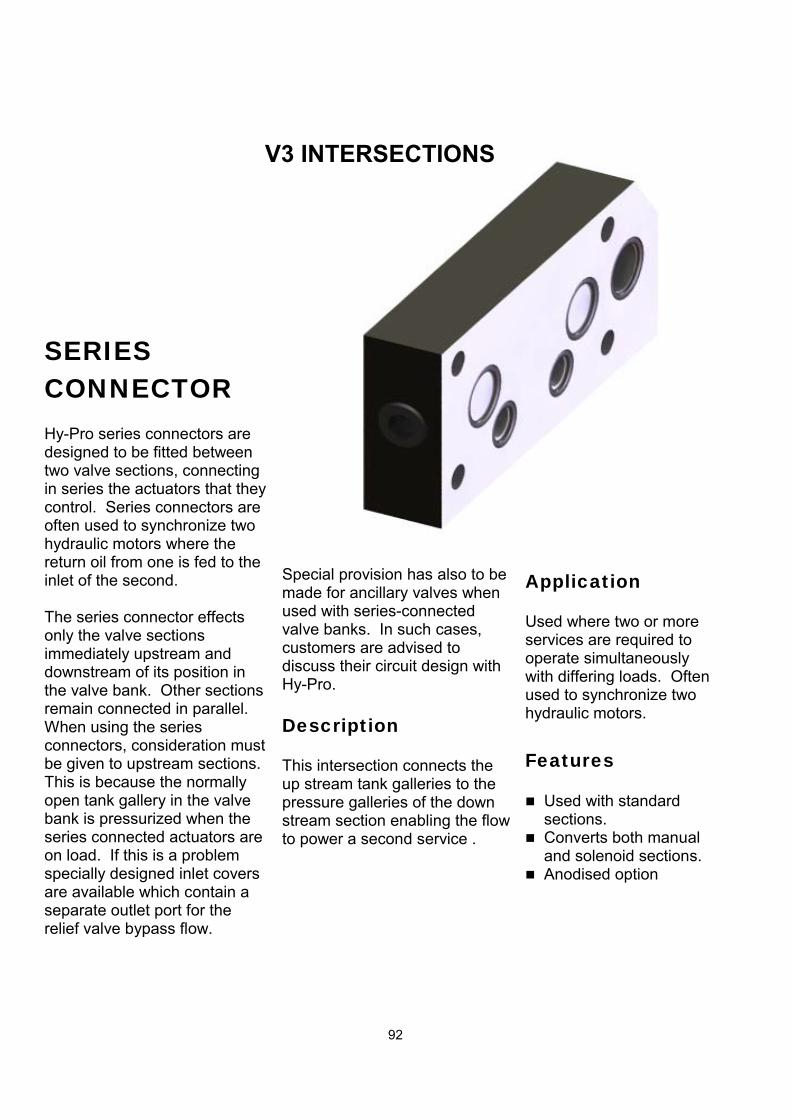
SERIES CONNECTOR Hy-Pro series connectors are designed to be fitted between two valve sections, connecting in series the actuators that they control. Series connectors are often used to synchronize two hydraulic motors where the return oil from one is fed to the inlet of the second. The series connector effects only the valve sections immediately upstream and downstream of its position in the valve bank. Other sections remain connected in parallel. When using the series connectors, consideration must be given to upstream sections. This is because the normally open tank gallery in the valve bank is pressurized when the series connected actuators are on load. If this is a problem specially designed inlet covers are available which contain a separate outlet port for the relief valve bypass flow.
Special provision has also to be made for ancillary valves when used with series-connected valve banks. In such cases, customers are advised to discuss their circuit design with Hy-Pro.
Description This intersection connects the up stream tank galleries to the pressure galleries of the down stream section enabling the flow to power a second service .
Application Used where two or more services are required to operate simultaneously with differing loads. Often used to synchronize two hydraulic motors.
Features Used with standard
sections. Converts both manual
and solenoid sections. Anodised option
V3 INTERSECTIONS
93
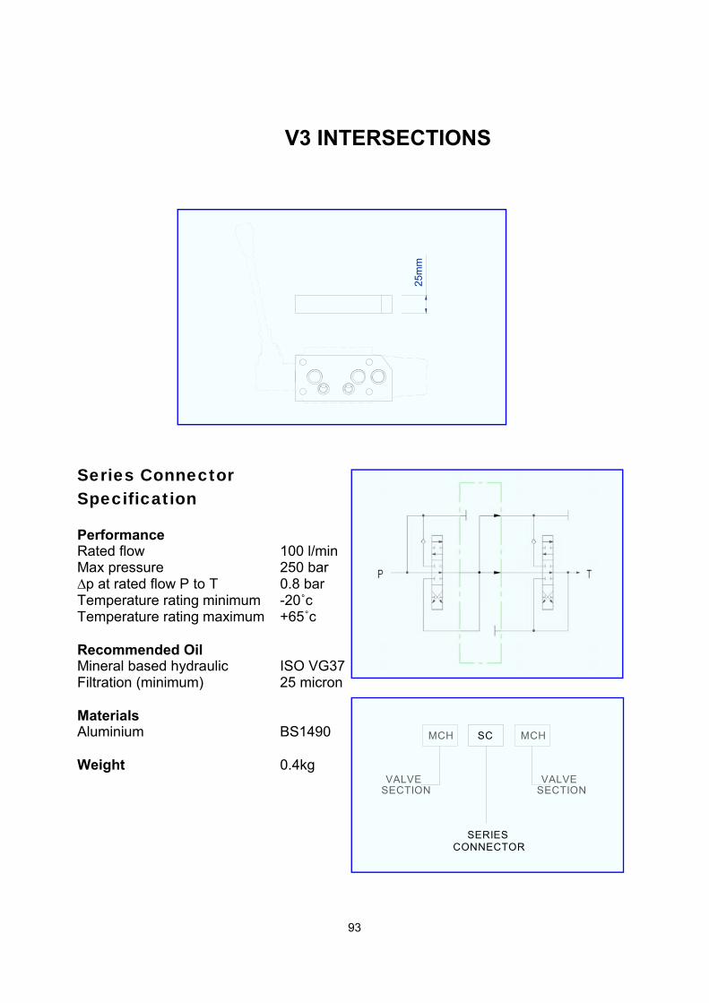
Series Connector Specification Performance Rated flow 100 l/min Max pressure 250 bar ∆p at rated flow P to T 0.8 bar Temperature rating minimum -20˚c Temperature rating maximum +65˚c Recommended Oil Mineral based hydraulic ISO VG37 Filtration (minimum) 25 micron Materials Aluminium BS1490 Weight 0.4kg
MCH SC MCH
VALVESECTION SECTION
VALVE
SERIESCONNECTOR
25m
m
V3 INTERSECTIONS

94
Application Used extensively in the forestry and fishing industry to control the speed of conveyors and winches.
V3-100 ROTARY LEVER
Description The Hy-Pro rotary lever has been developed specifically to enable the operator precise control of motors and cylinders. The lever swings through an 180° arc and works by means of a scroll which converts the rotary action of the lever into axial movement of the spool. The centring mechanism has a friction detent feature which positively holds the spool in neutral then maintains the
Because of the geometry of the lever it is not possible to include it in multi-section valves but it is retro-fitable to existing V3-100 single
Features 180° movement. Compact design. Spool options. Detent in neutral. Friction hold. Robust mechanism. Toughened components. Cast iron Body and scroll Retro fit-able.
V3 CONTROL
ORDER CODE
ORBITAL
CENTRING MECHANISM
O
FUNCTION &
O HO
LEVER MECHANISM
ORBITALHOREFER PAGE 8
INTERFACE
FOR VALVE SECTIONORDER CODE
SECTION
95
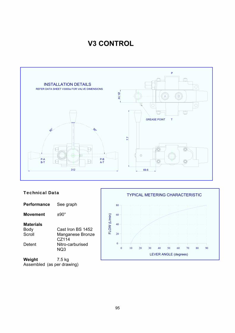
Technical Data Performance See graph Movement ±90° Materials Body Cast Iron BS 1452 Scroll Manganese Bronze CZ114 Detent Nitro-carburised NQ3 Weight 7.5 kg Assembled (as per drawing)
T
P
44.1
ØGREASE POINT
69.6
B-TP-A P-B
A-T
90° 90°
7.7
INSTALLATION DETAILSREFER DATA SHEET V3000a FOR VALVE DIMENSIONS
312
10 20 30 40 50 60 70 800 90
0
20
40
60
80
LEVER ANGLE (degrees)
FLO
W (
L/m
in)
TYPICAL METERING CHARACTERISTIC
V3 CONTROL

96