utilization of the image processing concept for serially ... · utilization of the image processing...
TRANSCRIPT
Utilization of the Image Processing Concept for Serially Communicating an Image in Li-Fi
Environment Using MATLAB Jitu Prakash Dhar
Department of Electrical and Electronic Engineering Chittagong University of Engineering & Technology
Chittagong, Bangladesh.
Email: [email protected]
Abstract—This paper is based on the implementation of MATLAB programming for processing an image and then interfacing it with a Li-Fi(Light-Fidelity) transmitter and receiver circuit. Also arduino programming is used here for interfacing of the hardware circuits with control signals that facilitate the serial communication. Image processing program should be given to both transmitter and receiver circuit. Data transmission rate is calculated from oscilloscope and performance of the network is observed.
Keywords—Li-Fi, LED array, Arduino Mega, Photo-Transistor, MATLAB, Ampifier circuit.
I. INTRODUCTION Radio communication technique such as Wi-Fi which means Wireless Fidelity had been used for a long time to upload and download a file in internet. The major drawback of Wi-Fi is the limited bandwidth. This causes the system to use a little spectrum for transmitting and receiving data. Professor Harald had introduced a new communication technique called Light Fidelity by using low cost LED bulbs. In this method, white light rays acts as carrier wave which has a wide bandwidth and high luminous intensity. The modulating signal is the digitized data that contains streams of 1’s and 0’s. The high frequency LED light amplifies and flickers according to the data stream. Thus the emitted light carries the message of streams. The technique is very simple. When we send 1 the LED bulbs are ON and when we send 0 the LED bulbs are off. The flickering of light is so quick that a human eye can not follow it. The transmitted data is than passed through an atmospheric channel like air and then received by a light detector such as photo transistor. The signal is then demodulated into original data. After proper amplification by transistor amplifier the received signal is then recovered perfectly. An image can be represented by a function f(x,y) so that the resulting image has M rows and N columns.
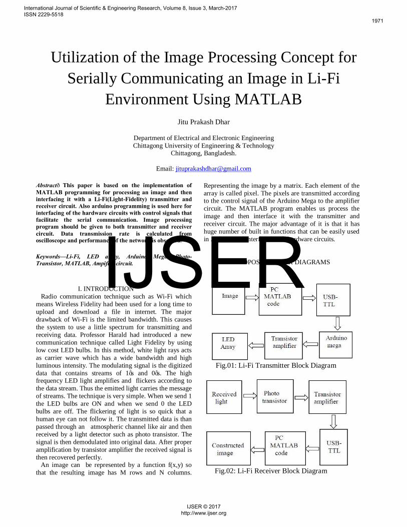
Representing the image by a matrix. Each element of the array is called pixel. The pixels are transmitted according to the control signal of the Arduino Mega to the amplifier circuit. The MATLAB program enables us process the image and then interface it with the transmitter and receiver circuit. The major advantage of it is that it has huge number of built in functions that can be easily used in Arduino and interfaced with hardware circuits. II. PROPOSED BLOCK DIAGRAMS
Fig.01: Li-Fi Transmitter Block Diagram
Fig.02: Li-Fi Receiver Block Diagram
International Journal of Scientific & Engineering Research, Volume 8, Issue 3, March-2017 ISSN 2229-5518
1971
IJSER © 2017 http://www.ijser.org
IJSER

III. PRACTICAL IMPLIMENTATION OF THE BLOCK DIAGRAMS On the basis of the block diagrams, the concept is visualized in PROTEUS circuit simulator. Both the transmitter and receiver circuit contains a common emitter transistor amplifier. Photo transistor is used as light detector in the receiver circuit.
Fig. 03: Simulated transmitter circuit
Fig. 04: Simulated Receiver circuit The simulated configurations are then practically implemented for image communication.
Fig. 05: Implemented Transmitter Circuit
Fig. 06: Implemented Receiver Circuit IV. MATLAB PROGRAMMING FOR PROCESSING THE IMAGE For sending laptop progam, first we have to read the image. Common function to read an image in MATLAB is imread(‘filename’). The image is converted from rgb image into gray image. This is done so because if we want send a rgb color image we will have create 3 vector fields which makes the programming quite complex. After reading the image file the serial COM port 25 is selected to interface the program code with Arduino Mega. The baudrate of Arduino is selected as 9600 and then the whole image matrix is transmitted with a pause of 0.001s and fwrite function. In the receiving laptop program, first the COM port 2 of the Arduino Mega is selected through which the bits are received. Then the command of receiving 10 bits at a time is given. The bits are then
International Journal of Scientific & Engineering Research, Volume 8, Issue 3, March-2017 ISSN 2229-5518
1972
IJSER © 2017 http://www.ijser.org
IJSER
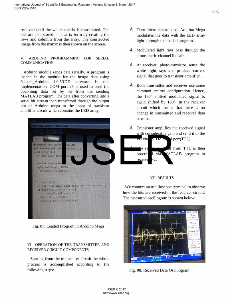
received until the whole matrix is transmitted. The bits are also stored in matrix form by creating the rows and columns from the array. The constructed image from the matrix is then shown on the screen. V. ARDUINO PROGRAMMING FOR SERIAL COMMUNICATION Arduino module sends data serially. A program is loaded in the module for the image data using ‘sketch_Arduino 1.0.5’IDE software. In this implementation, COM port 25 is used to send the upcoming data bit by bit from the sending MATLAB program. The data after converting into a serial bit stream than transferred through the output pin of Arduino mega to the input of transistor amplifier circuit which contains the LED array.
Fig. 07: Loaded Program in Arduino Mega
VI. OPERATION OF THE TRANSMITTER AND RECEIVER CIRCUIT COMPONENTS
Starting from the transmitter circuit the whole process is accomplished according to the following steps:
• Then micro controller of Arduino Mega modulates the data with the LED array light through the loaded program.
• Modulated light rays pass through the atmospheric channel like air.
• At receiver, photo-transistor sense the white light rays and produce current signal that goes to transistor amplifier.
• Both transmitter and receiver use same common emitter configuration. Hence, the 180o shifted modulated signal is again shifted by 180o in the receiver circuit which means that there is no change in transmitted and received data streams.
• Transistor amplifies the received signal with considerable gain and send it to the PC via USB to Serial port(TTL).
• The received signal from TTL is then processed via MATLAB program in receiver PC.
VII. RESULTS
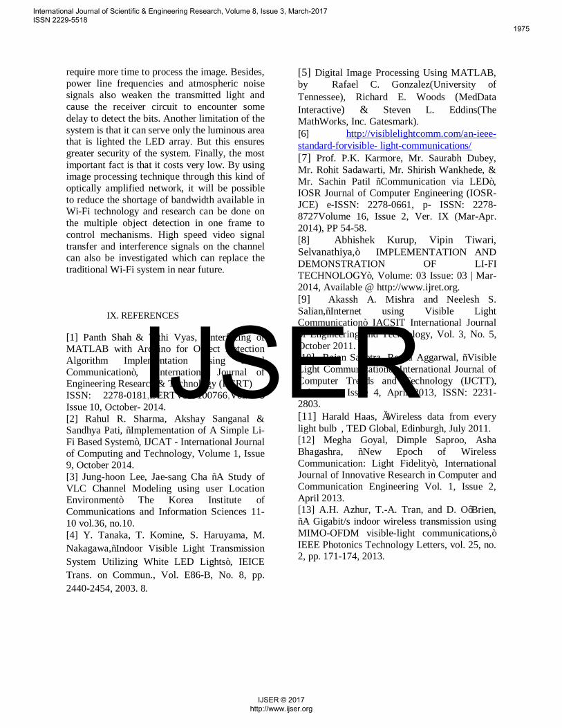
We connect an oscilloscope terminal to observe how the bits are received in the receiver circuit. The measured oscillogram is shown below:
Fig. 08: Received Data Oscillogram
International Journal of Scientific & Engineering Research, Volume 8, Issue 3, March-2017 ISSN 2229-5518
1973
IJSER © 2017 http://www.ijser.org
IJSER

2.5 bits are received in 250 micro seconds. Therefore, in one second the data received are (2.5/250X10-6)= 10,000 bits which is equal to 1.22kB/s. The results are tabulated below:
Table 01: System Performance Analysis
Measured Property Value Data speed 1.22kBps Maximum Distance 30cm
Fig. 09: Li- Fi Environment in the Laboratory
In this point to point communication network shown above, the whole image array takes approximately 8.2 seconds to transfer from the transmitter laptop to the receiver laptop. When the transmitter circuit sends bits it shows ‘ready..sending’ and when the receiver circuit receive bits it shows ‘go..receiving’ on the MATLAB command window. After sending the whole image the sender MATLAB window confirms it by displaying ‘finished’ while the receiver MATLAB window shows ‘showing results’. The transmitted and received images are shown below:
Fig. 10: Transmitted Image
Fig. 11: Received Image
VIII. CONCLUSION
The received image is gray because we transmitted a gray scale equivalent of the color image. However, it is possible to send a color image by creating RGB vector fields in MATLAB sending program and doing the same for detection of bits in the receiver MATLAB program. But such kind of task is complex
International Journal of Scientific & Engineering Research, Volume 8, Issue 3, March-2017 ISSN 2229-5518
1974
IJSER © 2017 http://www.ijser.org
IJSER
require more time to process the image. Besides, power line frequencies and atmospheric noise signals also weaken the transmitted light and cause the receiver circuit to encounter some delay to detect the bits. Another limitation of the system is that it can serve only the luminous area that is lighted the LED array. But this ensures greater security of the system. Finally, the most important fact is that it costs very low. By using image processing technique through this kind of optically amplified network, it will be possible to reduce the shortage of bandwidth available in Wi-Fi technology and research can be done on the multiple object detection in one frame to control mechanisms. High speed video signal transfer and interference signals on the channel can also be investigated which can replace the traditional Wi-Fi system in near future. IX. REFERENCES [1] Panth Shah & Tithi Vyas, “Interfacing of MATLAB with Arduino for Object Detection Algorithm Implementation using Serial Communication”, International Journal of Engineering Research & Technology (IJERT) ISSN: 2278-0181,IJERTV3IS100766,Vol. 3 Issue 10, October- 2014. [2] Rahul R. Sharma, Akshay Sanganal & Sandhya Pati, “Implementation of A Simple Li-Fi Based System”, IJCAT - International Journal of Computing and Technology, Volume 1, Issue 9, October 2014. [3] Jung-hoon Lee, Jae-sang Cha “A Study of VLC Channel Modeling using user Location Environment” The Korea Institute of Communications and Information Sciences 11-10 vol.36, no.10. [4] Y. Tanaka, T. Komine, S. Haruyama, M. Nakagawa,“Indoor Visible Light Transmission System Utilizing White LED Lights”, IEICE Trans. on Commun., Vol. E86-B, No. 8, pp. 2440-2454, 2003. 8.
[5] Digital Image Processing Using MATLAB, by Rafael C. Gonzalez(University of Tennessee), Richard E. Woods (MedData Interactive) & Steven L. Eddins(The MathWorks, Inc. Gatesmark). [6] http://visiblelightcomm.com/an-ieee-standard-forvisible- light-communications/ [7] Prof. P.K. Karmore, Mr. Saurabh Dubey, Mr. Rohit Sadawarti, Mr. Shirish Wankhede, & Mr. Sachin Patil “Communication via LED”, IOSR Journal of Computer Engineering (IOSR-JCE) e-ISSN: 2278-0661, p- ISSN: 2278-8727Volume 16, Issue 2, Ver. IX (Mar-Apr. 2014), PP 54-58. [8] Abhishek Kurup, Vipin Tiwari, Selvanathiya,” IMPLEMENTATION AND DEMONSTRATION OF LI-FI TECHNOLOGY”, Volume: 03 Issue: 03 | Mar-2014, Available @ http://www.ijret.org. [9] Akassh A. Mishra and Neelesh S. Salian,“Internet using Visible Light Communication” IACSIT International Journal of Engineering and Technology, Vol. 3, No. 5, October 2011. [10] Rajan Sagotra, Reena Aggarwal, “Visible Light Communication”, International Journal of Computer Trends and Technology (IJCTT), volume 4, Issue 4, April 2013, ISSN: 2231-2803. [11] Harald Haas, „Wireless data from every light bulb‟, TED Global, Edinburgh, July 2011. [12] Megha Goyal, Dimple Saproo, Asha Bhagashra, “New Epoch of Wireless Communication: Light Fidelity”, International Journal of Innovative Research in Computer and Communication Engineering Vol. 1, Issue 2, April 2013. [13] A.H. Azhur, T.-A. Tran, and D. O’Brien, “A Gigabit/s indoor wireless transmission using MIMO-OFDM visible-light communications,” IEEE Photonics Technology Letters, vol. 25, no. 2, pp. 171-174, 2013.
International Journal of Scientific & Engineering Research, Volume 8, Issue 3, March-2017 ISSN 2229-5518
1975
IJSER © 2017 http://www.ijser.org
IJSER