usm v5 deployment guide
TRANSCRIPT

USM Appliance™Deployment Guide
Updated February 12, 2018

Copyright © 2018 AlienVault. All rights reserved.
AlienVault, AlienApp, AlienApps, AlienVault OSSIM, Open Threat Exchange, OTX, Unified SecurityManagement, USM, USMAnywhere, USMAppliance, and USMCentral, are trademarks ofAlienVault and/or its affiliates. Other namesmay be trademarks of their respective owners.
2 USM Appliance™Deployment Guide
Contents
SystemOverview 6
About USM Appliance 7
About USM Appliance SystemArchitecture and Components 15
About USM Appliance Deployments 17
Event Collection, Processing, and CorrelationWorkflow 19
Deployment Requirements 23
MinimumHardware Requirements for USM Appliance Virtual Machines 24
Virtual Machine Requirements 24
Firewall Permissions 25
Supported Browsers 27
Deployment Planning 28
About the USM Appliance Components 29
About USM Appliance Deployment Types 29
USM Appliance Deployment Examples 30
USMAppliance Deployments 34
Configure the USM Appliance Hardware 35
DeployUSM Appliance in VMware 50
DeployUSM Appliance Using Hyper-V Manager 55
DeployUSM Appliance with AMI 60
Configure the USM Appliance Sensor after Deployment 63
Configure the USM Appliance Logger after Deployment 64
Set Up theManagement Interface 68
Register USMAppliance 69
USMAppliance Initial Setup 73
Access the AlienVault SetupMenu 74
USM Appliance™ Deployment Guide 3
Configure Network Interfaces 76
Configure the Search Domain 79
Configure a Hostname for USMAppliance 79
Change the Default Time Zone 80
Configure Synchronization with an NTP Server 81
Configure USM Appliance to Recognize Your Local Keyboard 81
Configure CustomHTTPS Certificates in USMAppliance 82
Create the Default Admin User 83
ConfigureMail Relay in USM Appliance 85
Getting StartedWizard 87
About the Getting StartedWizard 88
Running theGetting StartedWizard 90
IDS Configuration 101
About Intrusion Detection Systems 102
AlienVault HIDS 103
AlienVault NIDS 136
VPN Configuration 146
About Configuring a Virtual Private Network 147
Configuring a VPN Between USM Appliance Systems 147
Building a VPN TunnelWithout a Client-Server Connection 151
Verifying the VPN Connection 154
Disabling a VPN Configuration 154
High Availability Configuration 156
About High Availability 157
High Availability Prerequisites and Restrictions 158
Configuring High Availability in USM Appliance Standard Systems 160
Configuring High Availability in USM Appliance Enterprise Systems 172
Disabling High Availability 175
Upgrading a USM Appliance Deployment Configured for High Availability 176
PluginManagement 178
About Plugins 179
About Plugin Updates 184
4 USM Appliance™ Deployment Guide
Requesting a New Plugin or Update to an Existing Plugin 186
Creating Sample Log Files and Data for Requested Plugins 187
Enabling Plugins 189
Configuring Plugins 196
Customizing and Developing New Plugins 214
Update Process 243
About the USM Appliance Updates 244
Updating USM ApplianceOnline 245
Updating USM ApplianceOffline 248
Backup and Restoration 253
Backing Up and Restoring Alarms 254
Backing Up and Restoring Events 256
Backing Up and RestoringMongoDB 259
Backing Up and Restoring NetFlow Data 260
Backing Up and Restoring Raw Logs 263
Backing Up and Restoring SystemConfiguration 266
Migrating Your USM Appliance Deployment 271
Restoring Software on a USM Appliance Hardware 276
SystemMaintenance 282
Purging Old System Logs or Clearing SystemUpdate Caches 283
Updating the AlienVault License Key in USM Appliance 283
Replacing Disk Drives or Power Supplies on USM Appliance Hardware 284
Remote Support 290
About Remote Support 291
Remote Support Prerequisites 291
Using Remote Support 291
USM Appliance™ Deployment Guide 5
SystemOverview
This is a basic overview of AlienVault USM Appliance as it is deployed and used in yourenvironment. Individual subjects covered in the SystemOverview include the following:
l About USM Appliance — describes current risks in the business environment due to securitythreats and vulnerabilities, the role of risk assessment, an overview of USM Appliance securitymanagement capabilities for organizations to assess andmitigate risks, to detect threats and pri-oritize response, and to achieve compliance.
l About USM Appliance SystemArchitecture and Components — provides description of theUSM Appliance architecture, includingmajor system components and functionality.
l About USM Appliance Deployments — provides description of best practices for installation andconfiguration of USMAppliance.
l Event Collection, Processing, and CorrelationWorkflow — describes the overall USM Applianceworkflow, from collection of raw log data from networked devices to analyzing and determiningrisk from various threats and vulnerabilities.
USM Appliance™ Deployment Guide 6
About USM Appliance
Businesses today are exposed to an ever-increasing number of threats:
l Network-based threats — Aimed at networks and network infrastructure.
l Host-based threats — Aimed at individual hosts.
l External threats — Coming from external attackers.
l Internal threats — Coming from internal attackers.
Although the goal of security solutions is to detect and prevent such threats, no network can becompletely protected from them all. For this reason, USM Appliance focuses onmitigating risk,identifying vulnerabilities, detecting threats, and prioritizing response to the highest priority threatsand vulnerabilities. Measures for mitigating risk, identifying vulnerabilities, and detecting threatsinclude the following:
l Identifying patterns of events that indicate a possible threat or vulnerability.
l Determining the risk of potentially harmful attacks or compromise.
l Implementing controls to address reported vulnerabilities.
l Taking action to respond to identified attacks.
l Performing ongoingmonitoring and reporting of network and host-based activities.
TheRole of Risk Assessment
To properly secure your infrastructure, first conduct a risk assessment of your assets. Riskassessment helps you determine the relative importance of the assets within your network, thevulnerabilities of those assets in relation to specific exploitation threats, and the likelihood of securityevents taking place against those assets. After completing these analyses, you can design securitypolicies in response to the relative asset values and exploitation risks that various threats andvulnerabilities pose.
Strong security policies focus on how best to protect your most vital and at-risk assets. For example,if a network resource is critical and the likelihood of an attack against it is high, focus your efforts oncreating security policies that monitor for such attacks, and develop response plans to them.
How USM Appliance Helps with Risk Assessment and Mitigation
USM Appliance provides you with the ability to identify your critical assets and to set policies to alertyou when those assets have vulnerabilities or are subjected to attacks. USM Appliance will generatealarms based upon the risk associated with any given security event captured in USM Appliance.
The importance given to any given security event depends on three factors:
About USM Appliance
7 USM Appliance™ Deployment Guide
l The value of the asset associated with the event
l The threat represented by the event
l The probability that the event will occur
These factors are the building blocks for the traditional definition of risk: ameasure of the potentialimpact of a threat on your assets and the probability a threat will be carried out.
Each event generated in USM Appliance is evaluated in relation to its associated risk; in otherwords, in proportion to the assets at risk, the threat represented by the event, and the probability thethreat is real. Accordingly, USM Appliance provides you the capability to identify all high risk events,some of which will result in alarms, and allow you to properly prioritize your response.
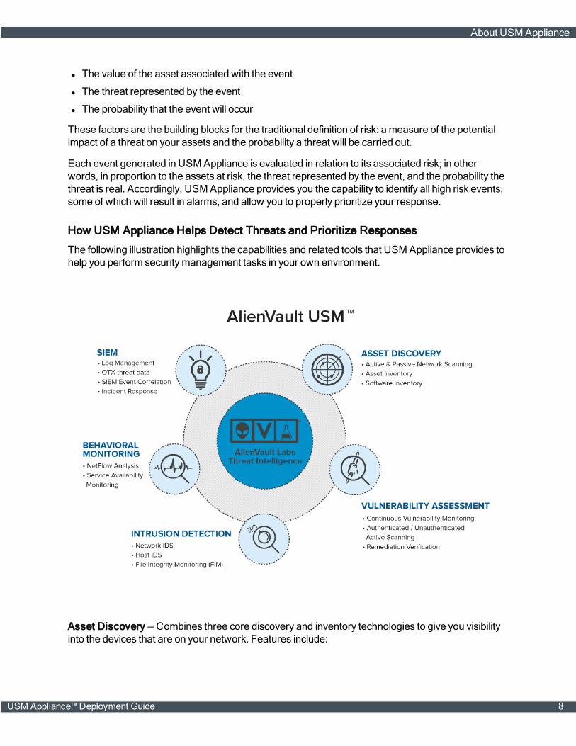
How USM Appliance Helps Detect Threats and Prioritize Responses
The following illustration highlights the capabilities and related tools that USM Appliance provides tohelp you perform securitymanagement tasks in your own environment.
Asset Discovery — Combines three core discovery and inventory technologies to give you visibilityinto the devices that are on your network. Features include:
About USM Appliance
USM Appliance™ Deployment Guide 8

l Active and Passive Network Scanning
l Asset Inventory
l Service Inventory
Performing asset discovery and inventory are the first essential steps to knowing what systems anddevices are on your network. USM Appliance combines three core discovery and inventorytechnologies to give you visibility into the devices you want to monitor.
Note: Before scanning a public network space, see AddendumNotice Regarding ScanningLeased or Public Address Space.
Vulnerability Assessment — Identifies assets and deviceswith unpatched software, insecureconfigurations, and other vulnerabilities on your network. Features include:
l Continuous VulnerabilityMonitoring
l Authenticated / Unauthenticated Active Scanning
l Remediation Verification
The integrated internal vulnerability scanning keeps you abreast of vulnerabilities on your network,so you can prioritize patch deployment and remediation. Continuous correlation of your dynamicasset inventory with our vulnerability database provides you with up-to-date information on thevulnerabilities in your network, in-between your scheduled scans.
Note: Before scanning a public network space, see AddendumNotice Regarding ScanningLeased or Public Address Space.
Intrusion Detection — Coordinates incident response and threat management across your networkwith built-in securitymonitoring technologies, emerging threat intelligence fromAlienVault Labs, andseamless closed-loop workflow for rapid remediation. Features include:
l Network-based IDS (NIDS)
l Host-based IDS (HIDS)
l File IntegrityMonitoring (FIM)
Built-in file integritymonitoring in host-based agents installed on servers alerts you to unauthorizedmodification of system files, configuration files or content. Monitoring of network access across bothwired and wireless networks using host- and network-based detection systems identifies who triedto access those systems, files, and content.
Behavioral Monitoring — Identifies anomalies and other patterns that signal new, unknown threatsin your network, as well as suspicious behavior and policy violations by authorized users anddevices. Features include:
l NetFlow Analysis
l Service AvailabilityMonitoring
l Network Protocol Analysis / Packet Capture
About USM Appliance
9 USM Appliance™ Deployment Guide
Integrated behavioral monitoring gathers data to help you understand “normal” system and networkactivity, which simplifies incident response when investigating a suspicious operational issue orpotential security incident. Full packet capture enables complete protocol analysis of network traffic,providing a comprehensive replay of the event that occurred during a potential breach.
Security Information and Event Management (SIEM) — Identify, contain, and remediate threats inyour network by prioritizing your risk and response. Features include:
l LogManagement
l IntegratedOTX Threat Data
l SIEMEvent Correlation
l Incident Response
You can automatically correlate log data with actionable security intelligence to identify policyviolations and receive contextually relevant and workflow-driven response procedures. You can alsoconduct forensic analysis of events using digitally signed raw logs. The raw logs also can be used tosatisfy compliance requirements for evidence preservation.
A web-based user interface provides access to all the securitymanagement functions provided byAlienVault USM Appliance. The USM Appliance User Guide provides information on accessing andusing all of the tools in USM Appliance and performing specific securitymanagement operationsfrom this user interface.
Managing Regulatory Compliance in USM Appliance
In addition to regular securitymanagement operations, USM Appliance also delivers essentialsecurity capabilities to help you achieve regulatory compliance. Through its built-in asset discovery,vulnerability assessment, intrusion detection, behavioral monitoring, logmanagement, and fileintegritymonitoring, USM Appliance can help organizations achieve compliance with regulationssuch as PCI DSS, GLBA, ISO/IEC 27001, FISMA, NERC CIP, FERPA, and SOX. USM Appliancealso generates built-in reports specifically for HIPAA, PCI, GLBA, ISO27001, FISMA, NERC CIP,GPG13, and SOX.
In addition, the "Using USM Appliance for PCI Compliance" section in the USM Appliance UserGuide provides detailed information on using USM Appliance to help achieve PCI DSS compliance.This information can also be useful in meeting compliance regulations for other standards aswell.
About AlienVault Threat Intelligence
AlienVault Threat Intelligence, integrated into USM Appliance through the Threat IntelligenceSubscription, providesUSM Appliance with capabilities that differentiate it frommost other securitymanagement solutions available in themarketplace today. AlienVault Threat Intelligence, developedby the AlienVault Labs Security Research Team and powered by theOpen Threat Exchange®(OTX™), is actionable information about the threats facing your network, including themalicious
About USM Appliance
USM Appliance™ Deployment Guide 10
actors, their tools, their infrastructure, and their methods. AlienVault Threat Intelligence tells youwhat the threat is, where it’s originating from, which assets in your environment are at risk, and howto respond.
AlienVault Labs
AlienVault Labs is AlienVault’s internal threat research team, consisting of security experts whoperform ongoing research and analysis of emerging global threats and vulnerabilities. This teamconstantlymonitors, analyzes, reverse-engineers, and reports on sophisticated zero-day threats,includingmalware, botnets, and phishing campaigns.
The team regularly publishes threat intelligence updates to the USM Appliance platform in the formof correlation directives, IDS signatures, vulnerability signatures, asset discovery signatures, IPreputation data, data source plugins, and report templates. The team also provides up-to-the-minuteguidance on emerging threats and context-specific remediation guidance, which accelerates andsimplifies threat detection and response.
The AlienVault Labs team also leverages the collective resources of OTX, the world’s largest crowd-sourced repository of threat data to provide global insight into attack trends andmalicious actors.AlienVault’s team of security experts analyze, validate, and curate the global threat data collected bytheOTX community.
The AlienVault Labs Threat Research team improves the efficiency of any securitymonitoringprogram by delivering the threat intelligence necessary to understand and address themost criticalissues in your networks. They perform the analysis, allowing you to spend your scarce timeremediating andmitigating the threats, rather than researching them.
Open Threat Exchange®
TheOpen Threat Exchange (OTX) is the world’smost authoritative open threat information sharingand analysis network. OTX provides open access to a global community of threat researchers andsecurity professionals. It now hasmore than 65,000 participants worldwide, who contribute over 14million threat indicators daily. It delivers community-generated threat data andOTX pulses, enablescollaborative research, and automates the process of updating your security infrastructure withthreat data from any source. OTX enables anyone in the security community to actively discuss,research, validate, and share the latest threat data, trends, and techniques, strengthening yourdefenseswhile helping others do the same.
TheOTX community and corresponding threat data is one of the critical data sources used by theAlienVault Labs team to generate AlienVault Threat Intelligence. AlienVault Labs leverages thecollective resources of the OTX by analyzing, validating, and curating the global threat datacontributed by theOTX community.
What Is Telemetry Collection and HowDoes It Work
About USM Appliance
11 USM Appliance™ Deployment Guide

At AlienVault we are continually striving to improve USM Appliance, by understanding how ourusers are interacting with the USM Appliance platform. Through anonymous usage data, we will beable to improve the product and user experience. In AlienVault USM Appliance version 5.0, weadded an optional Telemetry Collection capability to help us better understand how customers areusing our products and services.
Where Is the Telemetry Data Stored
AlienVault receives and stores the anonymized telemetry data on an internal server:telemetry.alienvault.com. The server certificates are signed byGoDaddy and all USM Applianceinstances have the necessary certificates in order to connect to this external server. Telemetry datais sent at 2:00 am local time on Sundays.
Note: Pleasemake sure to update your firewall rules to allow outbound connections totelemetry.alienvault.com through port 443 should you choose to use this feature.
How Is Telemetry Data Gathered in a Distributed Deployment
If you have a distributed deployment of USM Appliance, for example, a USM Appliance Server, aUSM Appliance Sensor, and/or a USM Appliance Logger, your USM Appliance Server will gatherthe telemetry data from the connected USMAppliance instances. In other words, theUSM Appliance Sensor and USM Appliance Logger will not send telemetry data themselves, but willsend data through the USM Appliance Server.
What Types of Data are Collected
We collect the following platform information:
l Average EPS
l Plugins installed
l Plugins being used
l Installedmemory
l Kernel configuration information
l USM Appliance version and date last updated
l Deployment architecture
l Number of assets beingmonitored
l Configured network interfaces
l USMAppliance type
l USMAppliance configuration
l USMAppliance instances in use
l USMAppliance Sensor / Remote Sensor configurations
l Number of cores used
About USM Appliance
USM Appliance™ Deployment Guide 12

l Commands running
l Disk I/O
l Disk size
l Redis health status
l VPN in use
l Number of users on the system
l Use of AlienVault OTX™
You can view a sample file of the anonymous data collected. And to learnmore about informationusage, please review our privacy policy.
Enabling/Disabling Telemetry Collection
Enabling/Disabling for the First Time
After the AlienVault USM Appliance system is deployed and registered, the first time you access itfrom the webUI, you are prompted to create an administrator account. At the bottom of the page,notice the option "Send anonymous usage statistics and system data to AlienVault to improveUSM Appliance". It is selected by default, whichmeans telemetry collection will be enabled. Todisable telemetry collection, deselect this option.
Enabling/Disabling at Any Time
Telemetry collection can be enabled or disabled in version 5.x at any time. In the webUI, navigate toConfiguration > Administration > Main, and open the User Activity selection. Locate "Sendanonymous usage statistics and system data to AlienVault to improve USM Appliance", select Yesto enable, or No to disable.
UnauthorizedModification of USM Appliance Can Lead to Instability
AlienVault USM Appliance are built to provide customerswith an easy-to-use solution to helpmonitor the security of their infrastructures. They are delivered in three form factors:
l Hardware appliances,
l Virtual appliances, and
l Amazon appliances.
These appliances include the AlienVault operating system and USM Appliance software necessaryto provide the built-in Unified SecurityManagement® (USM) security capabilities.
The appliances include an option to access the CLI of the appliance from the AlienVault Console.This is done by selecting the "Jailbreak System" option from the AlienVault Setupmenu, whichprovides limited shell access to the appliance. This option is available to help customers troubleshootnetwork issues, data collection issues, and to help the AlienVault Support teamworkwith you toresolve any issues you encounter with the product while working on a support case.
About USM Appliance
13 USM Appliance™ Deployment Guide
As per the AlienVault Terms and Conditions, AlienVault does not allow modification of system levelconfiguration files, database, or the underlying tools used to provide the functional capabilitiesoffered by the product. Although AlienVault has integrated various open source tools, theconfigurations used byUSM Appliance are designed to provide explicit functionality as described inthe product documentation. Changesmade to the operating system, tool configurations, or softwarecan destabilize the appliance and prevent the appliance fromworking properly.
Modifications to the operating system, tool configurations, or softwaremay lead to instability, thusrequire a reset of the appliance to factory settings to resolve it. AlienVault discourages customersfrommaking suchmodifications. If there is a use case that requires you to jailbreak the device, weencourage you to share with us the details of the use case and wewill consider the idea for a futurerelease of the product.
Our goal is to provide a simple, stable, easy-to-use security platform to help youmonitor yourenvironment for threats. Keeping the system stable and free from suchmodificationswill preventunnecessary downtime, performance issues, andmaintenance.
If you have any questions, please contact AlienVault Technical Support. for assistance.
How to Submit a Security Issue to AlienVault
Weare alwaysworking to improve the security of our products. You, the AlienVault community, aidour ability to deliver secure software for our customers — so thanks in advance!
Discovered a security vulnerability? Disclose it to us through our HackerOne program athttps://hackerone.com/alienvault_security. You can find further information of what domainswecurrently undertake on this page.
What Vulnerability Information Are We Looking For?
When submitting an issue, please provide a technical description that allows us to assessexploitability and impact of the issue, and include the following where appropriate:
l Provide steps and any additional information wemay need to reproduce the issue.
l If you are reporting cross-site scripting (XSS), your exploit should at least pop up an alert in thebrowser. It ismuch better if the XSS exploit shows the user's authentication cookie.
l For a cross-site request forgery (CSRF), use a proper CSRF case when a third party causes thelogged-in victim to perform an action.
l For a SQL injection, we want to see the exploit extracting database data, not just producing anerror message.
l HTTP request / response captures or simply packet captures are also very useful to us.
Please refrain from sending us links to non-AlienVault websites, or issues in PDF / DOC / EXE files.Image files are OK. Make sure the bug is exploitable by someone other than the user ("self-XSS").
About USM Appliance
USM Appliance™ Deployment Guide 14
Note: We are unable to respond to generic scanner reports. If you have had a securitypractitioner examine a generic scan report and they have isolated specific vulnerabilities thatneed to be addressed, we request that you report them individually.
Addendum Notice Regarding Scanning Leased or Public Address Space
AlienVault USM Appliance and AlienVault OSSIM™ contain a number of built-in tools for asset andnetwork discovery, enumeration, and vulnerability scanning. These tools utilize variousmethods fordiscovery, often bymimicking the behavior of the traffic which they are attempting to protect you fromin order to ascertain your exposure to such traffic. This leaves the potential for legitimate scans to bemisinterpreted asmalicious traffic.
In an effort to combat malicious behavior on the internet, several internet service providers andhosting providers have added scanning restrictions in their contracts. And a number of countrieshave written laws regarding these practices. In many cases, the response for violation of these rulesmay range from awritten warning to contract cancellation and even civil or criminal charges. As aresult, it is very important to checkwith your internet service providers, hosting providers, and localgovernment to establish any legal or contractual restrictions before attempting to scan hosts ornetworks outside of your internal network space.
About USM Appliance System Architecture and Components
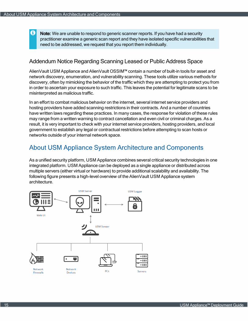
As a unified security platform, USM Appliance combines several critical security technologies in oneintegrated platform. USM Appliance can be deployed as a single appliance or distributed acrossmultiple servers (either virtual or hardware) to provide additional scalability and availability. Thefollowing figure presents a high-level overview of the AlienVault USM Appliance systemarchitecture.
About USM Appliance SystemArchitecture and Components
15 USM Appliance™ Deployment Guide
The three components of the USM Appliance architecture that work together to monitor and providesecurity in your environment are
l USM Appliance Sensor(s) — Deployed throughout the network to collect and normalize inform-ation from any devices in your network environment that you want to manage withUSM Appliance. A wide range of plugins are available to process raw logs and data from varioustypes of devices such as firewalls, routers, and host servers.
l USM Appliance Server — Aggregates and correlates information that the USM ApplianceSensors gather. (This is USM Appliance’s SIEM capability.) Provides single pane-of-glassman-agement, reporting, and administration through a web-based user interface.
l USM Appliance Logger — Securely archives raw event log data for forensic research and com-pliancemandates. (This archive of raw event data is also referred to as cold storage.)
Basic USM ApplianceWorkflow
There is a consistent workflow that USM Appliance follows in collecting raw data from networkdevices, then parsing and normalizing that data into a stream of events which can then be stored,filtered, and correlated to identify threats and vulnerabilities.
1. USM Appliance Sensors passively collect logs andmirrored traffic, and actively probe assets inthe network, to obtain information about the current network activity going on in your environment..
2. The USM Appliance Sensor parses the raw data from different sources and transforms it into astream of events, each having a common set of data fields. It then sends the events to theUSM Appliance Server.
3. The USM Appliance Server correlates the events and assesses their risk.
4. The USM Appliance Server sends the events to the USM Appliance Logger, which signs themdigitally and stores them for forensic analyses, archival, and regulatory compliance.
For amore in-depth description of event collection and processing, see About Plugins. Also refer tothe "About the Use of Policies in USM Appliance" and "About Correlation" topics in theUSM Appliance User Guide.
USM Appliance Deployment Options
AlienVault USM Appliance can be deployed in one of two basic configurations:
l Simple Deployment Model — All USM Appliance components (Sensor, Server, and Logger) arecombined in a USM Appliance All-in-One appliance. This configuration ismost often used in smal-ler environments, as well as for demonstrations and proof-of-concept deployments.
l Multi-tier, Distributed Deployment Model — Thismodel deploys each AlienVault USM Appliancecomponent (Sensor, Server, and Logger) as an individual virtual or hardware appliance to createa distributed system topology.
About USM Appliance SystemArchitecture and Components
USM Appliance™ Deployment Guide 16

The distributed deployment model also comes in two versions, USM Appliance Standard andUSM Appliance Enterprise, that increase scalability and performance by provisioning dedicatedsystems for each USM Appliance component. See USM Appliance Deployment Examples for moredetails on USM Appliance deployment models and examples.
About USM Appliance Deployments
USM Appliance is designed to provide an easy-to-deploy and easy-to-operate securitymanagementsolution. It is particularly well suited for small-to-medium sized businesseswho, similar to largerenterprises, need to ensure the security of their network environment, but may not have as large asupport staff to set up andmanagemore complex securitymanagement systems.
In addition to being easier to set up and operate thanmost alternative systems, USM Appliance alsohas amodular architecture that provides flexibility in configuring both performance and capacity. TheUSM Appliance All-in-One appliance combines all of the components of the USM Appliance solutionin a single virtual or hardwaremachine. In addition, based on the present or future needs of yourspecific environment, you can also scale individual components in the USM Appliance architectureto run on dedicatedmachines, add sensors to collect logs frommore devices and networks, andimplement other features such as high availability, monitoring of devices on remote networks, andremotemanagement of USM Appliance.
Note: For more information and a summary of deployment and configuration options, refer toAbout USM Appliance Deployment Types. This section also provides examples of differentsize and scale deployment configurations of USM Appliance.
Deployment Sizing and Scaling
There are numerous factors that can influence your USM Appliance configuration and the specificUSM Appliance architecture you choose to deploy. The principal factor is the number of events persecond that the devices in your environment might be expected to produce. In estimating the totalvolume of events, you need to include all devices in your environment that you want to monitor andmanage with USM Appliance (including firewalls, routers, and host servers, as well as installedapplications) and estimate the aggregate activity on these devices.
In addition, youmay need to consider other aspects of the specific securitymanagement use casesyou plan to addresswith your USM Appliance deployment. For example:
l Specific regulatory compliance requirements youmay have.
l Number and different types of devices you want to monitor.
l Number of users of your systems.
l Specific requirements for event correlation, data storage, and archiving youmay have.
Your AlienVault technical representative can help you analyze your environment to determinesystem requirements and can provide you with a questionnaire that lists different factors affectingsystem sizing and scaling, which can help you choose the right system configuration.
About USM Appliance Deployments
17 USM Appliance™ Deployment Guide

Note: The AlienVault USM Appliance data sheet, available athttps://www.alienvault.com/resource-center/data-sheets/unified-security-management-data-sheet, describes typical event handling performance and capacity benchmarks for a number ofdifferent USM Appliance system configurations and options.
Installation, Setup, and Configuration
USM Appliance is relatively simple to install and configure. To enable fast deployment in yourspecific environment, the USM Appliance All-in-One includes aGetting StartedWizard to guide youthrough some of the initial set-up tasks. In virtual environments, USM Appliance is packaged as avirtual machine that can be easily installed and configured using virtual resources, such as thosemanaged by VMware ESX or Hyper-V. See Virtual Machine Requirements for more details.
Some of the high level steps in performing USM Appliance configuration include the following:
l Installation of USM Appliance in network topology (DHCP or manual selection of IP addresses ofUSM Appliance components)
l Opening firewall ports for USM Appliance components, if required. See Firewall Permissions
l Setup of local or remote (IPMI or HPE iLO) USM Appliancemanagement
l Changing the root password
l Appliance registration
l Time zone and NTP server synchronization
l USM Appliance Sensor configuration
l USM Appliance Server and USM Appliance Logger configuration
l Connection to corporatemail server for email notifications
l Setup of additional configuration options, such as high availability, VPN, and plug-in installationand customization
You can use the AlienVault Setupmenu to performmost of these tasks. Information on performingthese tasks is provided in the USMAppliance Initial Setup section.
The AlienVault USM ApplianceGetting StartedWizard
Theweb-based AlienVault USM ApplianceGetting StartedWizard is available for theUSM Appliance All-in-One appliance to quickly get you up and running and starting to useUSM Appliance and accessing all of its built-in security capabilities. The wizard walks you through asimple, step-by-step workflow to do the following:
l Configure interfaces to beginmonitoring network traffic for threats.
l DeployHIDS agents in bulk.
l Connect your USM Appliance installation to OTX.
About USM Appliance Deployments
USM Appliance™ Deployment Guide 18
l Run a discovery scan to detect and inventory assets and systems.
l Start monitoring asset logs.
l Develop a response plan to alarms that are generated based on suspicious activity.
TheGetting StartedWizard section guides you through each step of the Getting StartedWizard.Other topics in this guide cover additional optional configuration tasks aswell as configuration ofdifferent size and scale deployment models.
Where to Go from Here
Following completion of its initial installation and configuration, USM Appliance is ready to use. Youcan begin tomonitor events. You can also implement and refine policy and correlation rules todiscover potential threats and vulnerabilities, as you observe network traffic and the behavior ofdevices in your environment. All of the tools that USM Appliancemakes available to you to performsecuritymanagement are accessible through the webUI.
The USM Appliance User Guide provides topics to help you perform all the different securitymanagement operations that USM Appliance provides. In addition, there are additional knowledgebase articles available from the AlienVault Documentation Center, plus training courses availablefromAlienVault to help you gain further expertise in using AlienVault USM Appliance.
Event Collection, Processing, and Correlation Workflow
All AlienVault USM Appliance's securitymonitoring andmanagement capabilities stem from itsoverall ability to collect data from devices, transform the data into a common set of data fields thatdefine events, and then process, filter, and correlate those events to identify potential threats andvulnerabilities, or real occurrences of attacks. USM Appliance also assesses the importance andpriority of events by assigning risk values based on the value of the underlying assets, the sourceand nature of the identified threat, and the likelihood of successful attack. More detail on this overallworkflow is provided in this section for the following topics:
l Log Data Collection, Parsing, and Normalization
l Event Processing and Filtering
l Event Correlation, Alarms, and Notification
l Event Visualization and Analysis
Log Data Collection, Parsing, and Normalization
Log collection is at the root of AlienVault securitymanagement. AlienVault USM Appliance collectslogs from various sources: network devices, such as firewalls and routers, host servers and systems,and software applications running on servers. Some devices, for example, those that support theSyslog protocol, are configured to send their logs directly to the USM Appliance Sensor. For otherdevices, USM Appliance goes out and retrieves the logs. In both cases, data in the logs isnormalized to extract and store information in common data fields that define an event: IP
Event Collection, Processing, and CorrelationWorkflow
19 USM Appliance™ Deployment Guide
addresses, host names, user names, interface names, and so on. These are the events that asecurity analyst can analyze in USM Appliance to uncover threats and vulnerabilities, and assess anorganization's risk.
Log Parsing Using Plugins
Running on a USM Appliance Sensor, an AlienVault USM Appliance agent is configured with acollection of different log-parsing plugins, which define how to collect logs from specific devices,systems, or applications, and how to transform that log data into standardized event data fieldsbefore sending the events to the USM Appliance Server. The plugins also control other event-gathering functions on the sensor, such as intrusion detection. USM Appliance comes equipped withplugins for many commonly encountered data sources. Contact AlienVault to request a new pluginfor any data source or product for which a plugin does not already exist. You can also create yourown custom plugins, or customize USM Appliance’s existing plugins.
Normalization of Security Events
Nomatter the format of a logmessage, certain pieces of data (such as user names or IP andMACaddresses) are common in all of the device logs. Extracting these values out of the logmessage textand storing them intomatching common fields is called normalization. Normalization is what allowsyou to perform queries across events collected from varied sources (for example, “Show all eventswhere the source IP is 192.168.1.3”.) Although the format of the original data collected from devicesmay be different, similar information across devices is stored in the same field for events sent to theUSM Appliance Server.
The logs are broken down into their message type, and the information from them is used topopulate a standard set of fields that define an event (for example, date, sensor, plugin_id, priority,src_ip, src_port, dst_ ip, dst_port, username, userdata1).
Note: For a complete list of normalized event fields, see "Event Details – Fields" in theUSM Appliance User Guide.
Event Processing and Filtering
After normalizing the data obtained from log files and other sources, the USM Appliance Sensortransmits security events to the USM Appliance Server. The USM Appliance Server also performsseveral additional operations on incoming events, including:
l Parsing the event priority and reliability — Each event type is assigned a priority, which indicateshow urgently the event should be investigated, and a reliability score, which assesses the chancethe event is a false positive.
l Checking asset values to calculate a risk score — The USM Appliance Server maintains an invent-ory of known devices on the network, with an associated asset value for each device, definingtheir importance to the organization. This asset value is then weighed against the event’s priorityand reliability score to produce a risk value. Higher risk scores help analysts know what ismostimportant to examine first.
Event Collection, Processing, and CorrelationWorkflow
USM Appliance™ Deployment Guide 20
For more information on how USM Appliance calculates risk, see "USM Appliance NetworkSecurity Concepts and Terminology" in the USM Appliance User Guide.
l Application of the event taxonomy — There are system and network events common acrossmanysystem types, nomatter the source of the event or its original data format. AlienVault maintains ahierarchical categorization of event types (referred to as a taxonomy) to which USM Appliancecanmatch events in policies and correlation directives.
l Cross-checking reputation data — The USM Appliance Server checks the IP addresses specificto each event against a reputation database of Internet addresses. IP addresses that match areflagged for future reference and follow-up.
After performing these operations, and based on specified user policy and filter conditions, theUSM Appliance Server will save selected or qualified events in a SIEM events database for furtheranalysis and correlation. The events database commonly resides on the same host as theUSM Appliance Server, but in large deployments, the database can be installed on a separate hostfor increased performance and capacity.
Event Correlation, Alarms, and Notification
Following the basic processing, analysis, and filtering that the USM Appliance Server performs,selected or qualified events are fed into the AlienVault USM Appliance correlation engine. UsingAlienVault USM Appliance correlation, analysts can look for patterns and sequences of eventsacrossmultiple devices and system types. Eventsmay actually be processed by the correlationengine several times, as different correlation rulesmay take the same events as input.
Correlation directives create alarms
As events continue to feed into the correlation engine, USM Appliance generates alarms based onevent conditions specified in correlation directives or rules:
l Alarm processing starts when the conditions of a correlation directive aremet.
l Alarmsmay trigger on a single event matching certain conditions, or may require a specificsequence of events to trigger.
l Alarm processingmay continue over amatter of hours. Alarms that appear in the systemmayindicate they are still processing additional incoming events to further corroborate detection.
l Alarms are themselves events (directive events), that can feed into other correlation directivesonce they are triggered, so you can create cascading levels of alarms.
In addition, when you sign up for the Open Threat Exchange® (OTX™), USM Appliance isconfigured to receive raw “pulse” data and indicators of compromise (IOCs), fromOTX.USM Appliance correlates that data and alerts you to any related OTX pulse and IP reputation-related security events and alarmswhen it detects those same IOCs interacting with assets in yourenvironment.
Event Collection, Processing, and CorrelationWorkflow
21 USM Appliance™ Deployment Guide
As soon as you log into USM Appliance, you can see from the USM Appliance dashboard whichOTX indicators are active in your environment. You will receive immediate notification in the form ofan event or an alarmwhen amalicious IP address identified in OTX communicateswith any of yoursystem assets, or when USM Appliance identifies any other IOCs seen in OTX are active in yournetwork.
Note: For more information about how USM Appliance alarms are processed and correlated,see "About Alarms" in the USM Appliance User Guide.
Event Visualization and Analysis
Events obtained from device logs, as well as those generated by the correlation engine itself, can allbe searched, viewed, and reported on from the USM Appliance webUI. Two different options areavailable to access and view events:
l View of security events with options to search, filter, and group events based on specific eventfield values. To use this option, select Analysis > Security Events (SIEM) from the webUI.
l View of raw log events displayed with a specific time frame. To use this option, select Analysis >Raw Events from the webUI.
For more information on viewing events and performing other securitymanagement operations fromthe USM Appliance webUI, see "Reviewing Security Events (SIEM)" and "Reviewing the RawLogs" in the USM Appliance User Guide.
Event Collection, Processing, and CorrelationWorkflow
USM Appliance™ Deployment Guide 22
Deployment Requirements
Before deploying USM Appliance, carefully go through the requirements to ensure a successfuldeployment.
This section covers the following subtopics:
MinimumHardware Requirements for USM Appliance Virtual Machines 24
Virtual Machine Requirements 24
Firewall Permissions 25
Supported Browsers 27
USM Appliance™ Deployment Guide 23
Minimum Hardware Requirements for USM Appliance VirtualMachines
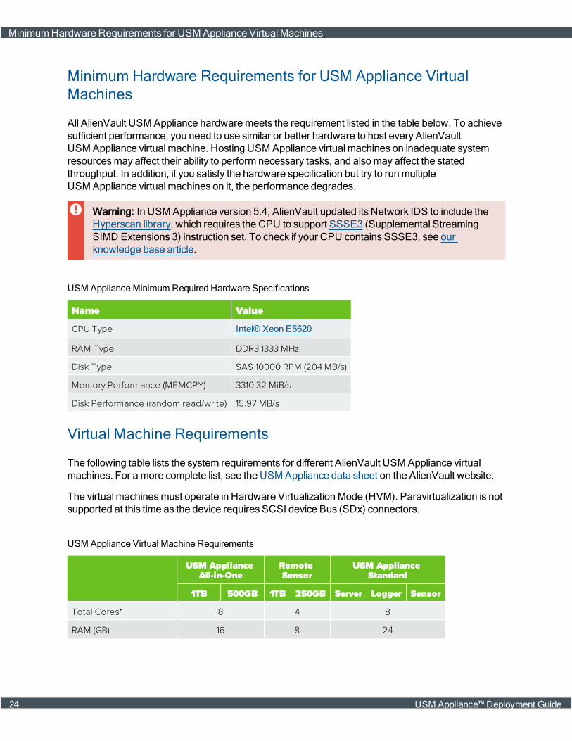
All AlienVault USM Appliance hardwaremeets the requirement listed in the table below. To achievesufficient performance, you need to use similar or better hardware to host every AlienVaultUSM Appliance virtual machine. Hosting USM Appliance virtual machines on inadequate systemresourcesmay affect their ability to perform necessary tasks, and alsomay affect the statedthroughput. In addition, if you satisfy the hardware specification but try to runmultipleUSM Appliance virtual machines on it, the performance degrades.
Warning: In USM Appliance version 5.4, AlienVault updated its Network IDS to include theHyperscan library, which requires the CPU to support SSSE3 (Supplemental StreamingSIMD Extensions 3) instruction set. To check if your CPU contains SSSE3, see ourknowledge base article.
Name Value
CPU Type Intel® Xeon E5620
RAM Type DDR3 1333 MHz
Disk Type SAS 10000 RPM (204 MB/s)
Memory Performance (MEMCPY) 3310.32 MiB/s
Disk Performance (random read/write) 15.97 MB/s
USM ApplianceMinimum Required Hardware Specifications
Virtual Machine Requirements
The following table lists the system requirements for different AlienVault USM Appliance virtualmachines. For amore complete list, see the USM Appliance data sheet on the AlienVault website.
The virtual machinesmust operate in Hardware VirtualizationMode (HVM). Paravirtualization is notsupported at this time as the device requires SCSI device Bus (SDx) connectors.
USM ApplianceAll-in-One
RemoteSensor
USM ApplianceStandard
1TB 500GB 1TB 250GB Server Logger Sensor
Total Cores* 8 4 8
RAM (GB) 16 8 24
USM Appliance Virtual Machine Requirements
MinimumHardware Requirements for USM Appliance Virtual Machines
24 USM Appliance™ Deployment Guide

USM ApplianceAll-in-One
RemoteSensor
USM ApplianceStandard
1TB 500GB 1TB 250GB Server Logger Sensor
Storage (TB) 1.0 0.5 1.0 0.25 1.2 1.8 1.2
VirtualizationEnvironment
VMware ESXi 4.x, 5.x, 6.x
Hyper-V v3.0+ (Windows Server 2008 SP2 and later)
USM Appliance Virtual Machine Requirements (Continued)
* Total Cores are available physical cores without hyperthreading enabled.
Additional Steps If You Are Running VMware ESXi 4.x
Even though VMware no longer supports ESXi 4.x, AlienVault continues to test runningUSM Appliance on ESXi 4.x to make sure it works appropriately. If you are running VMware ESXi4.x, there are some additional steps youmust perform.
Turning Off Hyper-Threading
In VMware vSphere Clients, hyper-threading is enabled by default. This is not a concern for ESXi5.x or 6.x hosts. But for ESXi 4.x, because their maximumnumber of virtual processors per virtualmachine is 8 (see VMware's ConfigurationMaximums supported by vSphere 4.1 in PDF format fordetails), youmust disable hyper-threading to ensure CPU performance. For instructions on how toturn hyper-threading off, see VMware's documentation.
Possible File Size Issues with VMFS-3 Datastores
VMware ESXi 5.x and 6.x support VMFS-5 datastores allowingmaximum virtual disk sizes close to2 TB. This satisfies the USM Appliance storage requirement so you don't need tomake anyadjustment. We recommend using a VMFS-5 datastore where this is available.
A VMware ESXi datastore based on VMFS-3 will not support the USM Appliance disk files unlessthe datastore was created with a block size of 8MB. By default VMFS-3 datastores have a block sizeof 1MB, limiting themaximum file size to 256GB. To deployUSM Appliance on an ESX 4.x system,we recommend using a VMFS-3 datastore with a block size of 8MB. It may be necessary to create anew datastore with a block size of 8MB if none already exists. For more information on this, see theVMware knowledge base article Increasing the block size of local VMFS storage in ESX 4.x duringinstallation.
Firewall Permissions
USM Appliance componentsmust use particular URLs, protocols, and ports to function correctly.
Firewall Permissions
USM Appliance™ Deployment Guide 25

Note: If deploying USM Appliance All-in-One, you only need to open the ports associated withthemonitored assets, because All-in-One includes both USM Appliance Server andUSM Appliance Sensor, therefore the communication between them becomes internal.
If your company operates in a highly secure environment, youmust change some permissions onyour firewall(s) for USM Appliance to gain access.
Server URL Port Number AlienVault Features in Use Applicable Release
data.alienvault.com 80 AlienVault product and feed update All
maps-api-ssl.google.com 443 Asset Location All
messages.alienvault.com 443 Message Center All
telemetry.alienvault.com 443 Telemetry Data Collection All
tractorbeam.alienvault.com 22, 443 Remote Support All
www.google.com1 80 AlienVault API All
reputation.alienvault.com 443 AlienVault IP Reputation All
otx.alienvault.com 443 Open Threat Exchange 5.1+
External URLs and port numbers used by USM Appliance features
1The AlienVault API tries to access www.google.com every five minutes to ensure that the sys-tem has an Internet connection.
The following diagram shows the port numbers used by the USM Appliance components tocommunicate with each other and with themonitored assets. The direction of the arrows indicate thedirection of the network traffic.
Firewall Permissions
26 USM Appliance™ Deployment Guide
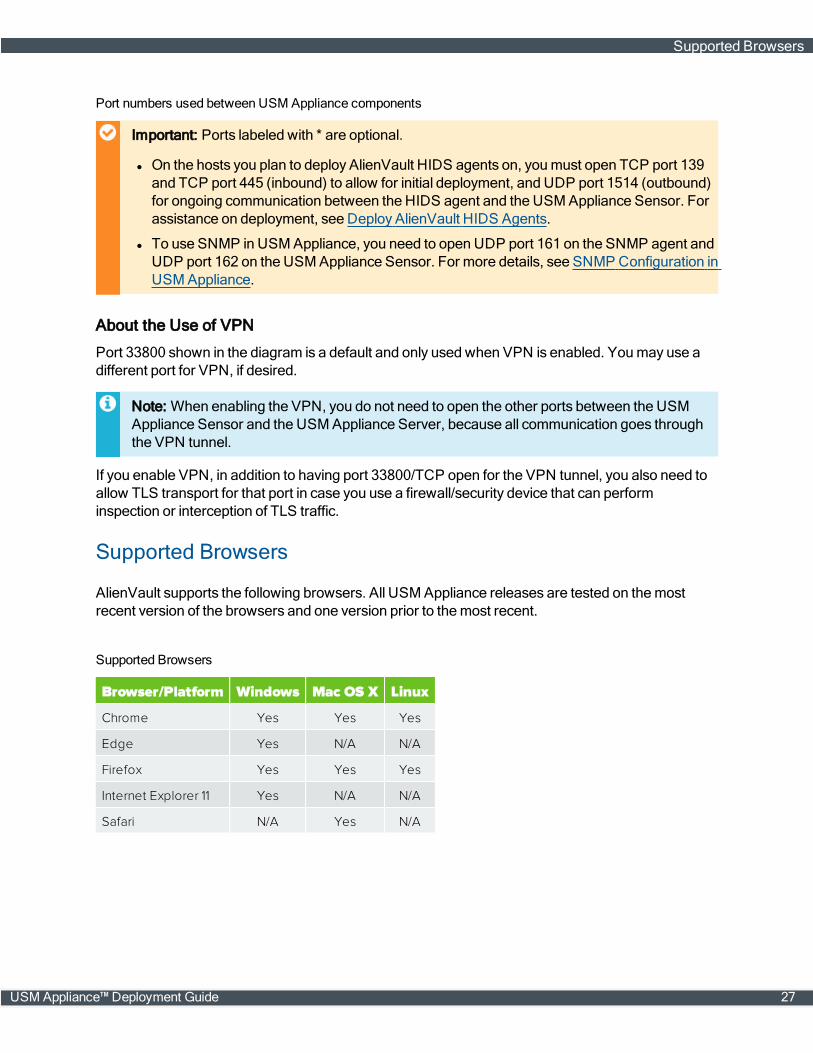
Port numbers used between USM Appliance components
Important: Ports labeled with * are optional.
l On the hosts you plan to deploy AlienVault HIDS agents on, youmust open TCP port 139and TCP port 445 (inbound) to allow for initial deployment, and UDP port 1514 (outbound)for ongoing communication between the HIDS agent and the USMAppliance Sensor. Forassistance on deployment, see Deploy AlienVault HIDS Agents.
l To use SNMP in USMAppliance, you need to open UDP port 161 on the SNMP agent andUDP port 162 on the USMAppliance Sensor. For more details, see SNMP Configuration inUSM Appliance.
About the Use of VPN
Port 33800 shown in the diagram is a default and only used when VPN is enabled. Youmay use adifferent port for VPN, if desired.
Note: When enabling the VPN, you do not need to open the other ports between the USMAppliance Sensor and the USMAppliance Server, because all communication goes throughthe VPN tunnel.
If you enable VPN, in addition to having port 33800/TCP open for the VPN tunnel, you also need toallow TLS transport for that port in case you use a firewall/security device that can performinspection or interception of TLS traffic.
Supported Browsers
AlienVault supports the following browsers. All USM Appliance releases are tested on themostrecent version of the browsers and one version prior to themost recent.
Browser/Platform Windows Mac OS X Linux
Chrome Yes Yes Yes
Edge Yes N/A N/A
Firefox Yes Yes Yes
Internet Explorer 11 Yes N/A N/A
Safari N/A Yes N/A
Supported Browsers
Supported Browsers
USM Appliance™ Deployment Guide 27

Deployment Planning
These topics help hardware and software deployment managers successfully deploy AlienVaultUSM Appliance.
l What USM Appliance components are part of the solutionmy company purchased?
See About the USM Appliance Components.
l How do the USM Appliance deployment solutions differ from each other?
See About USM Appliance Deployment Types.
l How does topology change according to which USM Appliance solutionmy companypurchased?
SeeUSM Appliance Deployment Examples.
USM Appliance™ Deployment Guide 28
About the USM Appliance Components
All USM Appliance products include these three core components available as hardware or virtualappliances:
USM Appliance Sensor
TheUSM Appliance Sensor is deployed throughout the network to collect logs andmonitor networktraffic. It provides the five essential USM Appliance security capabilities – Behavioral Monitoring,SIEM, Intrusion Detection, Asset Discovery, and Vulnerability Assessment – for complete visibility.
Theremust be at least one USM Appliance Sensor. Depending on your corporate requirements,moremay be desirable. This is particularly true if you have distributed branches on subnetssubordinate to the network at your headquarters.
USM Appliance Server
Aggregates and correlates information that the Sensors gather. Provides single-pane-of-glassmanagement, reporting, and administration.
There is usually just one USM Appliance Server.
USM Appliance Logger
Securely archives raw event log data for forensic research and compliancemandates.
There is usually just one USM Appliance Logger. However, under some circumstances, twomay beused. For information, contact AlienVault Technical Support.
Note: USM Appliance All-in-One combines the Server, Sensor, and Logger components ontoa single system.
About USM Appliance Deployment Types
You deploy AlienVault USM Appliance in one of two ways:
Simple Deployment
Deploys all AlienVault USM Appliance components—Sensor, Server, and Logger—in a singlehardware appliance called USM Appliance All-in-One.
This deployment model hasmost applicability for smaller environments, for testing, and fordemonstrations.
Complex/Distributed Deployment
Thismodel deploys each AlienVault USM Appliance component—Sensor, Server, and Logger—asan individual virtual or hardware appliance to create a distributed topology.
About the USM Appliance Components
29 USM Appliance™ Deployment Guide
This deployment model comes in two versions that increase scalability and performance byprovisioning dedicated systems for each component:
USM Appliance Standard
Consists of the following:
l USM Appliance Standard Server
l USM Appliance Standard Sensor
l USM Appliance Standard Logger
USM Appliance Enterprise
Consists of the following:
l USM Appliance Enterprise Server—Combines the Enterprise Server and Enterprise Database.
l USM Appliance Enterprise Sensors
l USM Appliance Enterprise Logger
Note: The USM Appliance Enterprise solution is not available as a virtual appliance.
For examples of deployment topography, see the USM Appliance Deployment Examples, on page30.
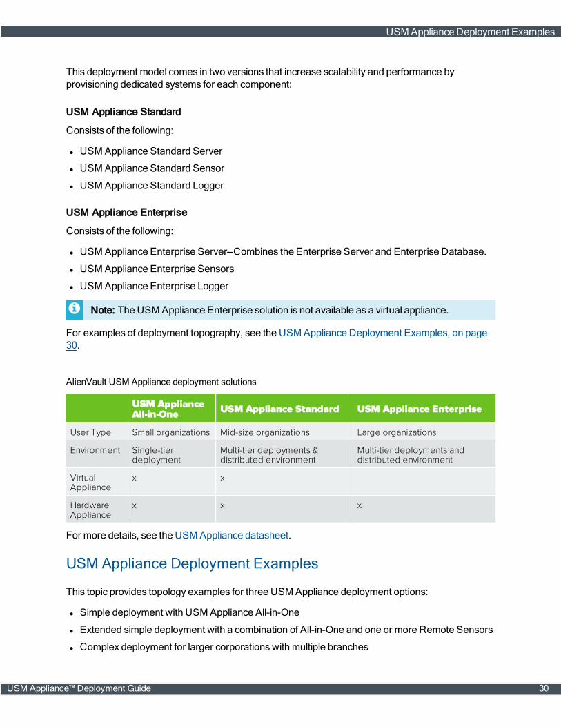
USM ApplianceAll-in-One USM Appliance Standard USM Appliance Enterprise
User Type Small organizations Mid-size organizations Large organizations
Environment Single-tierdeployment
Multi-tier deployments &distributed environment
Multi-tier deployments anddistributed environment
VirtualAppliance
x x
HardwareAppliance
x x x
AlienVault USM Appliance deployment solutions
For more details, see the USM Appliance datasheet.
USM Appliance Deployment Examples
This topic provides topology examples for three USM Appliance deployment options:
l Simple deployment with USM Appliance All-in-One
l Extended simple deployment with a combination of All-in-One and one or more Remote Sensors
l Complex deployment for larger corporationswith multiple branches
USM Appliance Deployment Examples
USM Appliance™ Deployment Guide 30
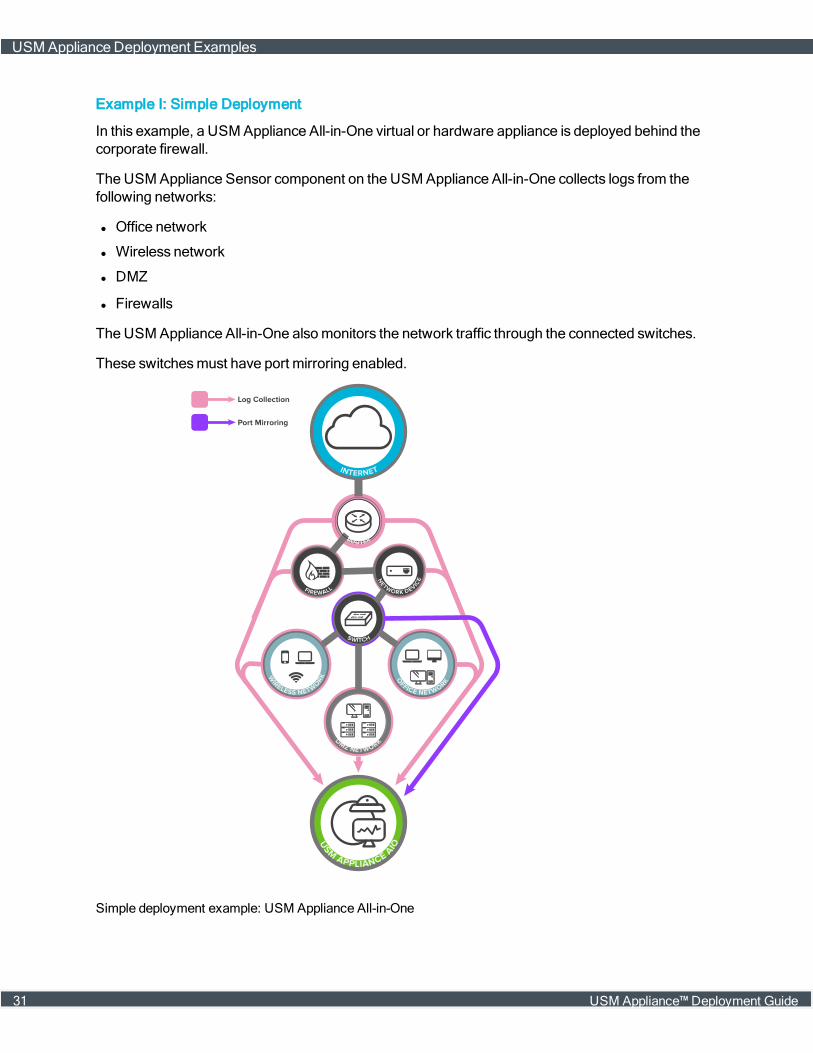
Example I: Simple Deployment
In this example, a USM Appliance All-in-One virtual or hardware appliance is deployed behind thecorporate firewall.
The USM Appliance Sensor component on the USM Appliance All-in-One collects logs from thefollowing networks:
l Office network
l Wireless network
l DMZ
l Firewalls
The USM Appliance All-in-One alsomonitors the network traffic through the connected switches.
These switchesmust have port mirroring enabled.
Simple deployment example: USM Appliance All-in-One
USM Appliance Deployment Examples
31 USM Appliance™ Deployment Guide
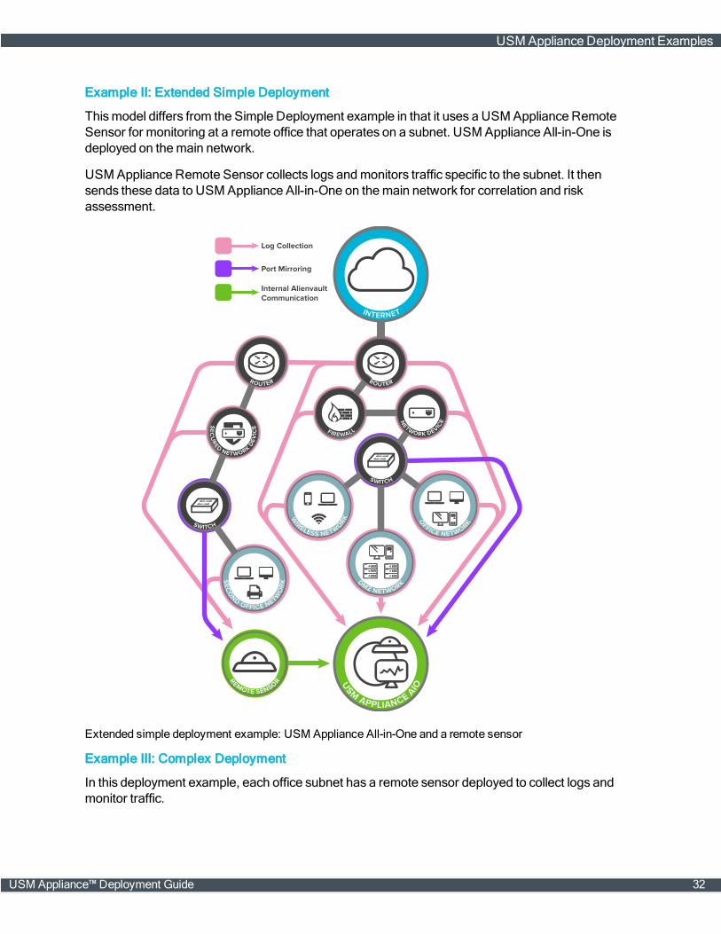
Example II: Extended Simple Deployment
Thismodel differs from the Simple Deployment example in that it uses a USM Appliance RemoteSensor for monitoring at a remote office that operates on a subnet. USM Appliance All-in-One isdeployed on themain network.
USM Appliance Remote Sensor collects logs andmonitors traffic specific to the subnet. It thensends these data to USM Appliance All-in-One on themain network for correlation and riskassessment.
Extended simple deployment example: USM Appliance All-in-One and a remote sensor
Example III: Complex Deployment
In this deployment example, each office subnet has a remote sensor deployed to collect logs andmonitor traffic.
USM Appliance Deployment Examples
USM Appliance™ Deployment Guide 32

On themain network at headquarters, a single USM Appliance Server, a Logger, and at least oneSensor install as individual appliances to increase scalability and performance.
All USM Appliance Sensors connect to one USM Appliance Server where correlation and riskassessment occur.
The USM Appliance Server forwards the events and alarms to the USM Appliance Logger for long-term storage.
Complex deployment example: individual USM Appliance components
USM Appliance Deployment Examples
33 USM Appliance™ Deployment Guide

USMAppliance Deployments
USM Appliance is designed to provide an easy-to-deploy and easy-to-operate securitymanagementsolution. It is particularly well suited for small-to-medium sized businesseswho, similar to largerenterprises, need to ensure the security of their network environment, but may not have as large asupport staff to set up andmanagemore complex securitymanagement systems.
Topics covered in this section include the following:
Configure the USM Appliance Hardware 35
DeployUSM Appliance in VMware 50
DeployUSM Appliance Using Hyper-V Manager 55
DeployUSM Appliance with AMI 60
Configure the USM Appliance Sensor after Deployment 63
Configure the USM Appliance Logger after Deployment 64
Set Up theManagement Interface 68
USM Appliance™ Deployment Guide 34
Configure the USM Appliance Hardware
You canmanage the USM Appliance hardware either locally or remotely, through the IPMI or HPEiLO interface. Enabling remotemanagement adds the ability to access the appliance if the operationsystem is not responsive or does not allow access from the network.
This section covers the following subtopics:
l Configure the USM Appliance Hardware Locally
l Configure the USM Appliance Hardware through IPMI
l Configure the USM Appliance Hardware through HPE iLO
Configure the USM Appliance Hardware Locally
Tomanage the USM Appliance hardware locally, youmust connect amonitor, mouse, andkeyboard to themachine.
Starting from version 5.4, AlienVault ships USM Appliance hardware built on Hewlett PackardEnterprise (HPE) ProLiant Gen9 Servers. All prior versions of USM Appliance hardware are built onSupermicro servers. For detailed hardware specifications, see the USM Appliance data sheet on theAlienVault website.
To connect to the USM Appliance hardware locally
1. Make sure that the appliance is powered off.
The power switch is located on the opposite side of the appliance from the cable ports.
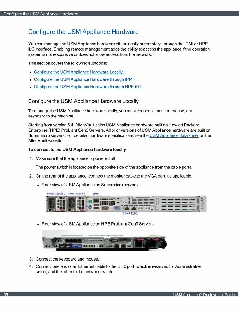
2. On the rear of the appliance, connect themonitor cable to the VGA port, as applicable.
l Rear view of USM Appliance on Supermicro servers
l Rear view of USM Appliance on HPE ProLiant Gen9 Servers
3. Connect the keyboard andmouse.
4. Connect one end of an Ethernet cable to the Eth0 port, which is reserved for Administrativesetup, and the other to the network switch.
Configure the USM Appliance Hardware
35 USM Appliance™ Deployment Guide
5. Cable the two power cables to each of the power ports on the left-rear side of the appliance andplug the other ends into a power strip.
6. Power on the appliance and turn on themonitor.
Themonitor displays the USM Appliance login screen. See Access the AlienVault SetupMenufor details.
Configure the USM Appliance Hardware through HPE iLO
Starting from version 5.4, AlienVault ships USM Appliance hardware built on Hewlett PackardEnterprise (HPE) ProLiant Gen9 Servers. Integrated Lights-Out (iLO) is a remote servermanagement processor embedded on the system boards of these servers. HPE iLOenables themonitoring and controlling of servers from remote locations. For security concerns, theUSM Appliance hardware provided byHPE has iLO disabled by default. You need to enable HPEiLO from the BIOS before you can use it. And should you choose to do it, AlienVault recommendsthat you restrict access to HPE iLOby configuring a secure virtual LAN (VLAN), andmake sure thatthe VLAN is connected to a secure network.
About HPE iLO Licensing
All USM Appliance hardware provided byHPE includes the HPE iLO4 standard featureswith noadditional cost or license requirements.
Before You Start
Before configuring HPE iLOonUSM Appliance, youmust have performed the following:
l Connect an Ethernet cable to USM Appliance through the HPE iLOmanagement port.
l Connect USM Appliance to a power outlet.
l Make sure you can reach USM Appliance over the network from themachine you are on.
l Install the Java version recommended byHPE on your machine. See the vendor website for up-to-date information.
l If not using DHCP, acquire the IP address you want to assign to HPE iLO.
Enabling HPE iLO
TheUSM Appliance hardware provided byHPE has iLO disabled by default. You need to enableHPE iLO from the BIOS before you can use it.
To enable HPE iLO
1. Power on or restart USM Appliance.
2. Press the F9 key, when prompted, to enter System Utilities.
3. Select System Configuration and then iLO 4 Configuration Utility.
Configure the USM Appliance Hardware
USM Appliance™ Deployment Guide 36

4. Select Setting Options and then change iLO 4 Functionality to "Enabled".
5. Press F10 to save your changes.
6. Restart the server.
Assigning Static IP Address to HPE iLO
TheHPE iLOon the USM Appliance hardware is pre-configured to obtain the IP address from aDHCP server. If you want to use a static IP address instead, you have to change the configurationfrom the systemBIOS.
To manually assign an IP address to HPE iLO
1. Power on or restart USM Appliance.
2. Press the F9 key, when prompted, to enter System Utilities.
3. Select System Configuration and then iLO 4 Configuration Utility.
4. Select Network Options:
a. Change DHCP Enable to "Off".
b. Enter IP Address, Subnet Mask, andGateway IP Address based on your network setting.
5. Press F10 to save your changes.
6. Restart the server.
Accessing the HPE iLO Web Interface
You can use the HPE iLOweb interface tomanage iLO. For browser support, see section 12 in theHPE iLO4User Guide.
To access the HPE iLO web interface
1. Open a web browser and type the IP address assigned to HPE iLO.
The IP address is displayed at the top right corner of the console during a systemPower-OnSelf-Test (POST).
2. Enter the user name and password shown on the sticker label of the appliance.
Each USM Appliance appliance includes a sticker label from themanufacturer, where you cansee the HPE iLO's default settings, including the serial number, user name, DNS name, andpassword.
3. Click Log In.
For security reasons, AlienVault recommends that you change the password after you havesuccessfully logged in. You can also add, delete, or edit users from the HPE iLOweb interface.
Enabling VLAN on HPE iLO
AlienVault recommends that you restrict access to HPE iLOby configuring a VLAN, andmake surethat the VLAN is connected to a secure network.
Configure the USM Appliance Hardware
37 USM Appliance™ Deployment Guide
To enable VLAN on HPE iLO
1. Login to the HPE iLOwebUI.
2. Navigate to Network > Shared Network Port.
3. On theGeneral tab, click Use Shared Network Port and leave the default selections for NICand Port unchanged.
4. To use a VLAN, click Enable VLAN.
Note: According to the HPE iLO4User Guide, when the Shared Network Port is activeand VLAN is enabled, the iLOShared Network Port becomes part of a VLAN. All networkdeviceswith different VLAN tagswill appear to be on separate LANs, even if they arephysically connected to the same LAN.
5. In the VLAN Tag field, type a value between 1 and 4094 to identify the VLAN.
All VLANsmust have a VLAN ID, and all network devices that you want to communicate witheach other must have the same VLAN tag.
6. Click Submit.
Disabling HPE iLO
TheUSM Appliance hardware provided byHPE has iLO disabled by default. You need to enableHPE iLO from the BIOS before you can use it. Should you decide to disable it later on, you can do sofrom the BIOS again.
To disable HPE iLO
1. Power on or restart USM Appliance.
2. Press the F9 key, when prompted, to enter System Utilities.
3. Select System Configuration and then iLO 4 Configuration Utility.
4. Select Setting Options and then change iLO 4 Functionality to "Disabled".
5. Press F10 to save your changes.
6. Restart the server.
Updating the HPE iLO Firmware
AlienVault recommends that you keep the HPE iLO firmware up to date. See the table below for theHPE iLO firmware versions on USM Appliance.
Configure the USM Appliance Hardware
USM Appliance™ Deployment Guide 38
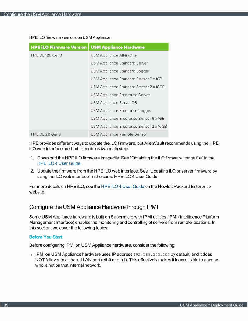
HPE iLO Firmware Version USM Appliance Hardware
HPE DL 120 Gen9 USM Appliance All-in-One
USM Appliance Standard Server
USM Appliance Standard Logger
USM Appliance Standard Sensor 6 x 1GB
USM Appliance Standard Sensor 2 x 10GB
USM Appliance Enterprise Server
USM Appliance Server DB
USM Appliance Enterprise Logger
USM Appliance Enterprise Sensor 6 x 1GB
USM Appliance Enterprise Sensor 2 x 10GB
HPE DL 20 Gen9 USM Appliance Remote Sensor
HPE iLO firmware versions on USM Appliance
HPE provides different ways to update the iLO firmware, but AlienVault recommends using the HPEiLOweb interfacemethod. It contains twomain steps:
1. Download the HPE iLO firmware image file. See "Obtaining the iLO firmware image file" in theHPE iLO4User Guide.
2. Update the firmware from the HPE iLO web interface. See "Updating iLO or server firmware byusing the iLOweb interface" in the sameHPE iLO4User Guide.
For more details on HPE iLO, see the HPE iLO4User Guide on the Hewlett Packard Enterprisewebsite.
Configure the USM Appliance Hardware through IPMI
SomeUSM Appliance hardware is built on Supermicro with IPMI utilities. IPMI (Intelligence PlatformManagement Interface) enables themonitoring and controlling of servers from remote locations. Inthis section, we cover the following topics:
Before You Start
Before configuring IPMI on USM Appliance hardware, consider the following:
l IPMI on USMAppliance hardware uses IP address 192.168.200.200 by default, and it doesNOT failover to a shared LAN port (eth0 or eth1). This effectivelymakes it inaccessible to anyonewho is not on that internal network.
Configure the USM Appliance Hardware
39 USM Appliance™ Deployment Guide
l AlienVault recommends that you deploy IPMI on an isolated network segment or virtual LAN(VLAN). In addition, configure the IPMI port to be dedicated. See Configuring a VLAN for IPMIAccess, on page 44.
l If the IPMI port must be accessed outside of the network security perimeter, set up a VPN serverto provide that access.
For more best practices onmanaging servers with IPMI features, see Supermicro's documentation.
Configuring USM Appliance (Except Remote Sensor) for IPMI
Follow these steps to configure IPMI on each USM Appliance hardware installation except theRemote Sensor, which is on a different IPMI firmware version. You should have connected amonitor and a keyboard to USM Appliance and an Ethernet cable to the IPMI port on the rear of themachine.
For IPMI configuration on the Remote Sensor, see Configuring USM Appliance Remote Sensor forIPMI, on page 42.
To configure IPMI on the USM Appliance hardware
1. Power on USM Appliance.
2. During startup, press and continuously hold Delete on the keyboard.
The BIOS SETUP UTILITY screen appears on themonitor.
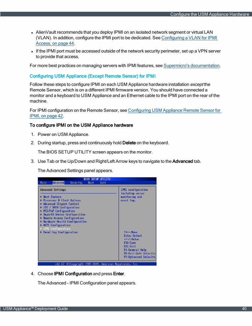
3. Use Tab or the Up/Down and Right/Left Arrow keys to navigate to the Advanced tab.
The Advanced Settings panel appears.
4. Choose IPMI Configuration and press Enter.
The Advanced - IPMI Configuration panel appears.
Configure the USM Appliance Hardware
USM Appliance™ Deployment Guide 40

5. Choose Set LAN Configuration and press Enter.
The Advanced - IPMI Configuration - Set LAN Configuration panel appears.
6. Choose amethod of assigning an IP address to themachine:
l If you have a DHCP server in the same network as the USM Appliance hardware, use theArrow keys to select IP Address Source, and then use plus (+) or minus(-) to change IP Address Source to DHCP.
l If you do not have a DHCP Server, use the arrow keys to select Static.
7. (Static IP address users only) Use the Arrow keys to access the IP Address, Subnet Mask, and
Configure the USM Appliance Hardware
41 USM Appliance™ Deployment Guide

GatewayAddress fields and type the appropriate values in each for your device.
Note: Eachmachine comeswith a default IP address; youmay either use this IP addressor configure a new one.
8. Save the changes by pressing F10, and then press ESC to exit the BIOS SETUP UTILITY.
9. Youmust restart themachine for your changes to take effect.
Configuring USM Appliance Remote Sensor for IPMI
The USM Appliance Remote Sensor requires its own IP address, netmask, and gateway IPaddresses.
To configure IPMI on a USM Appliance Remote Sensor
1. Power on themachine.
2. During startup, press and continuously hold Delete on the keyboard.
The Aptio Setup Utility appears on themonitor.
3. Using Tab or Arrow, select the IPMI tab.
Configure the USM Appliance Hardware
USM Appliance™ Deployment Guide 42
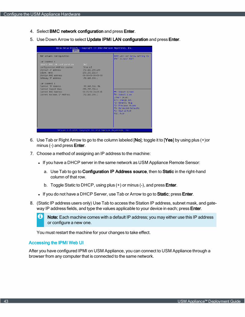
4. Select BMC network configuration and press Enter.
5. Use Down Arrow to select Update IPMI LAN configuration and press Enter.
6. Use Tab or Right Arrow to go to the column labeled [No]; toggle it to [Yes] by using plus (+)orminus (-) and press Enter.
7. Choose amethod of assigning an IP address to themachine:
l If you have a DHCP server in the same network asUSM Appliance Remote Sensor:
a. Use Tab to go to Configuration IP Address source, then to Static in the right-handcolumn of that row.
b. Toggle Static to DHCP, using plus (+) or minus (-), and press Enter.
l If you do not have a DHCP Server, use Tab or Arrow to go to Static; press Enter.
8. (Static IP address users only) Use Tab to access the Station IP address, subnet mask, and gate-way IP address fields, and type the values applicable to your device in each; press Enter.
Note: Eachmachine comeswith a default IP address; youmay either use this IP addressor configure a new one.
Youmust restart themachine for your changes to take effect.
Accessing the IPMI Web UI
After you have configured IPMI on USM Appliance, you can connect to USM Appliance through abrowser from any computer that is connected to the same network.
Configure the USM Appliance Hardware
43 USM Appliance™ Deployment Guide
To access USM Appliance IPMI through your browser
1. Open a browser on the computer that can accessUSM Appliance and type the IPMI IP addressassigned in the configuration step.
After a connection ismade, the Supermicro Login screen appears.
2. Type the default factory username "ADMIN" and password "4L13NV4ULT_0", then click Login.
Themain IPMI screen appears.
3. After you have successfully logged in, change the default password for security purposes.
Youmust then log in with the new password.
4. After logging in again, enable display of the remote USM Appliance console and configureredirection:
a. On the topmenu bar, click Remote Control.
b. In the navigation pane at left, select Console Redirection.
c. On the Console Redirection screen, click Launch Console.
Note: If the browser blocks it, click the top of themenu bar and select Download File. Thenopen it from your Downloads folder.
5. When you receive the Java prompt asking whether you want to run the application, click Run.
Note: If you receive a warning that the application is untrusted and asking if you want tomake an exception, click Continue.
Configuring a VLAN for IPMI Access
AlienVault recommends that you deploy IPMI as part of a VLAN.
This procedure describes how tomake your VLAN accessible to IPMI.
To configure VPN VLAN IPMI network settings
1. Log into themachine through the browser and enter the IPMI IP address you previously con-figured.
2. Go to Configuration > Network.
3. Within the VLAN section of the page, click enable.
4. In the VLAN ID field, type a value between 1 and 4095 to identify the VLAN.
5. (Optional) In the LAN interface list, select Dedicate.
By selecting Dedicate, you configure IPMI to connect over the IPMI port at all times. Otherwise,it fails over automatically to the two shared LAN ports (eth0 and eth1).
6. Click Save.
Configure the USM Appliance Hardware
USM Appliance™ Deployment Guide 44
Updating the IPMI Firmware
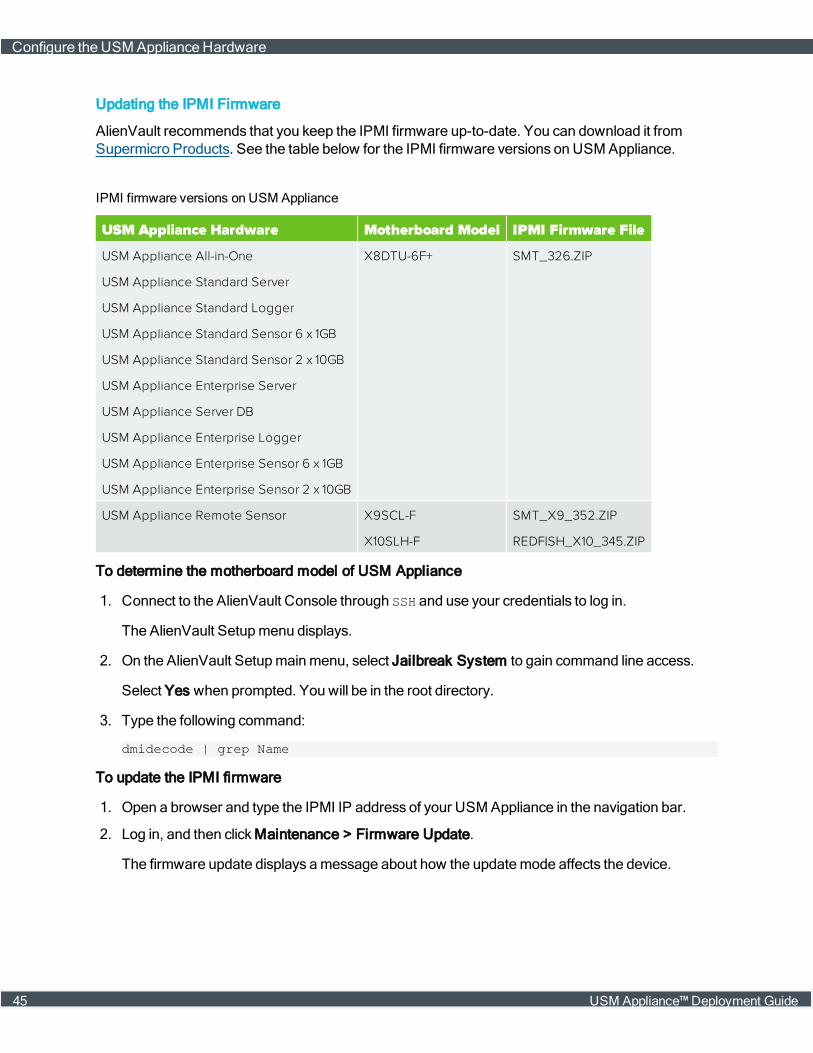
AlienVault recommends that you keep the IPMI firmware up-to-date. You can download it fromSupermicro Products. See the table below for the IPMI firmware versions on USM Appliance.
USM Appliance Hardware Motherboard Model IPMI Firmware File
USM Appliance All-in-One
USM Appliance Standard Server
USM Appliance Standard Logger
USM Appliance Standard Sensor 6 x 1GB
USM Appliance Standard Sensor 2 x 10GB
USM Appliance Enterprise Server
USM Appliance Server DB
USM Appliance Enterprise Logger
USM Appliance Enterprise Sensor 6 x 1GB
USM Appliance Enterprise Sensor 2 x 10GB
X8DTU-6F+ SMT_326.ZIP
USM Appliance Remote Sensor X9SCL-F
X10SLH-F
SMT_X9_352.ZIP
REDFISH_X10_345.ZIP
IPMI firmware versions on USM Appliance
To determine the motherboard model of USM Appliance
1. Connect to the AlienVault Console through SSH and use your credentials to log in.
The AlienVault Setupmenu displays.
2. On the AlienVault Setupmainmenu, select Jailbreak System to gain command line access.
Select Yes when prompted. You will be in the root directory.
3. Type the following command:
dmidecode | grep Name
To update the IPMI firmware
1. Open a browser and type the IPMI IP address of your USM Appliance in the navigation bar.
2. Log in, and then clickMaintenance > Firmware Update.
The firmware update displays amessage about how the updatemode affects the device.
Configure the USM Appliance Hardware
45 USM Appliance™ Deployment Guide

Important: After USM Appliance is in the firmware updatemode, the update processresets the IPMI device, even if you cancel the update.
3. Click Enter Update Mode and thenOK.
The page changes from Firmware Update to Firmware Upload.
4. Click Browse to choose the firmware file. Make sure that the firmware version is correct beforeproceeding.
5. Click Upload Firmware.
6. Select Preserve Configuration on the following page, so that the system does not change yourconfiguration during reboot.
Configure the USM Appliance Hardware
USM Appliance™ Deployment Guide 46
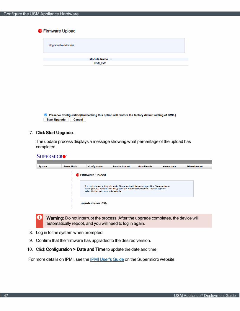
7. Click Start Upgrade.
The update process displays amessage showing what percentage of the upload hascompleted.
Warning: Do not interrupt the process. After the upgrade completes, the device willautomatically reboot, and you will need to log in again.
8. Log in to the systemwhen prompted.
9. Confirm that the firmware has upgraded to the desired version.
10. Click Configuration > Date and Time to update the date and time.
For more details on IPMI, see the IPMI User's Guide on the Supermicro website.
Configure the USM Appliance Hardware
47 USM Appliance™ Deployment Guide

Configure the USM Appliance Enterprise Server and Enterprise Database
The AlienVault USM Appliance Enterprise Server component is hardware only, and ships with twodevices — an Enterprise Server and an Enterprise Database.
The Enterprise Server needs to know the IP address and password of the Enterprise Database.Likewise, the Enterprise Database needs to know the IP address of the Enterprise Server. Thisinformation ensures that the two devices can communicate with each other.
Both configurations occur using the AlienVault Setupmenu.
Task 1: Start the USM Appliance Enterprise Server Configuration
Prerequisites
You should have already assigned an IP address to the Enterprise Server by following theprocedure Set Up theManagement Interface, on page 68.
To start the USM Appliance Enterprise Server configuration
1. On the AlienVault Setupmenu, use the Tab key to go to Configure Enterprise Server; pressEnter (<OK>).
2. When the AlienVault MySQLSetupmenu appears, move it to the background temporarily whileyou proceed with configuring the USM Appliance Enterprise Database.
You will return to this later.
Task 2: Start the USM Appliance Enterprise Database Configuration
Prerequisites
You should have already assigned an IP address to the Enterprise Database by following theprocedure .
To configure the USM Appliance Enterprise Database
1. On the AlienVault Setupmenu, use the Tab key to go to Configure Database; press Enter(<OK>).
2. On the Configure Databasemenu, use the Tab key to select Configure AlienVault Server IP;press Enter (<OK>).
3. In the Enter Server IP Address field, enter the IP address of the USM Appliance EnterpriseServer; press Enter (<OK>).
The Configure Databasemenu appears again.
4. Use the Tab key to select Configure AlienVault Framework IP; press Enter (<OK>).
Configure the USM Appliance Hardware
USM Appliance™ Deployment Guide 48
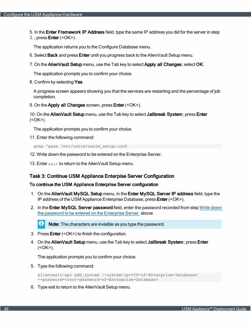
5. In the Enter Framework IP Address field, type the same IP address you did for the server in step3. ; press Enter (<OK>).
The application returns you to the Configure Databasemenu.
6. Select Back and press Enter until you progress back to the AlienVault Setupmenu.
7. On the AlienVault Setupmenu, use the Tab key to select Apply all Changes; select OK.
The application prompts you to confirm your choice.
8. Confirm by selecting Yes.
A progress screen appears showing you that the services are restarting and the percentage of jobcompletion.
9. On the Apply all Changes screen, press Enter (<OK>).
10. On the AlienVault Setupmenu, use the Tab key to select Jailbreak System; press Enter(<OK>).
The application prompts you to confirm your choice.
11. Enter the following command:
grep ^pass /etc/ossim/ossim_setup.conf
12.Write down the password to be entered on the Enterprise Server.
13. Enter exit to return to the AlienVault Setupmenu.
Task 3: Continue USM Appliance Enterpise Server Configuration
To continue the USM Appliance Enterprise Server configuration
1. On the AlienVault MySQL Setupmenu, in the Enter MySQL Server IP address field, type theIP address of the USM Appliance Enterprise Database; press Enter (<OK>).
2. In the Enter MySQL Server password field, enter the password recorded from stepWrite downthe password to be entered on the Enterprise Server. above.
Note: The characters are invisible as you type the password.
3. Press Enter (<OK>) to finish the configuration.
4. On the AlienVault Setupmenu, use the Tab key to select Jailbreak System; press Enter(<OK>).
The application prompts you to confirm your choice.
5. Type the following command:
alienvault-api add_system –-system-ip=<IP-of-Enterprise-Database>--password=<root-password-of-Enterprise-Database>
6. Type exit to return to the AlienVault Setupmenu.
Configure the USM Appliance Hardware
49 USM Appliance™ Deployment Guide
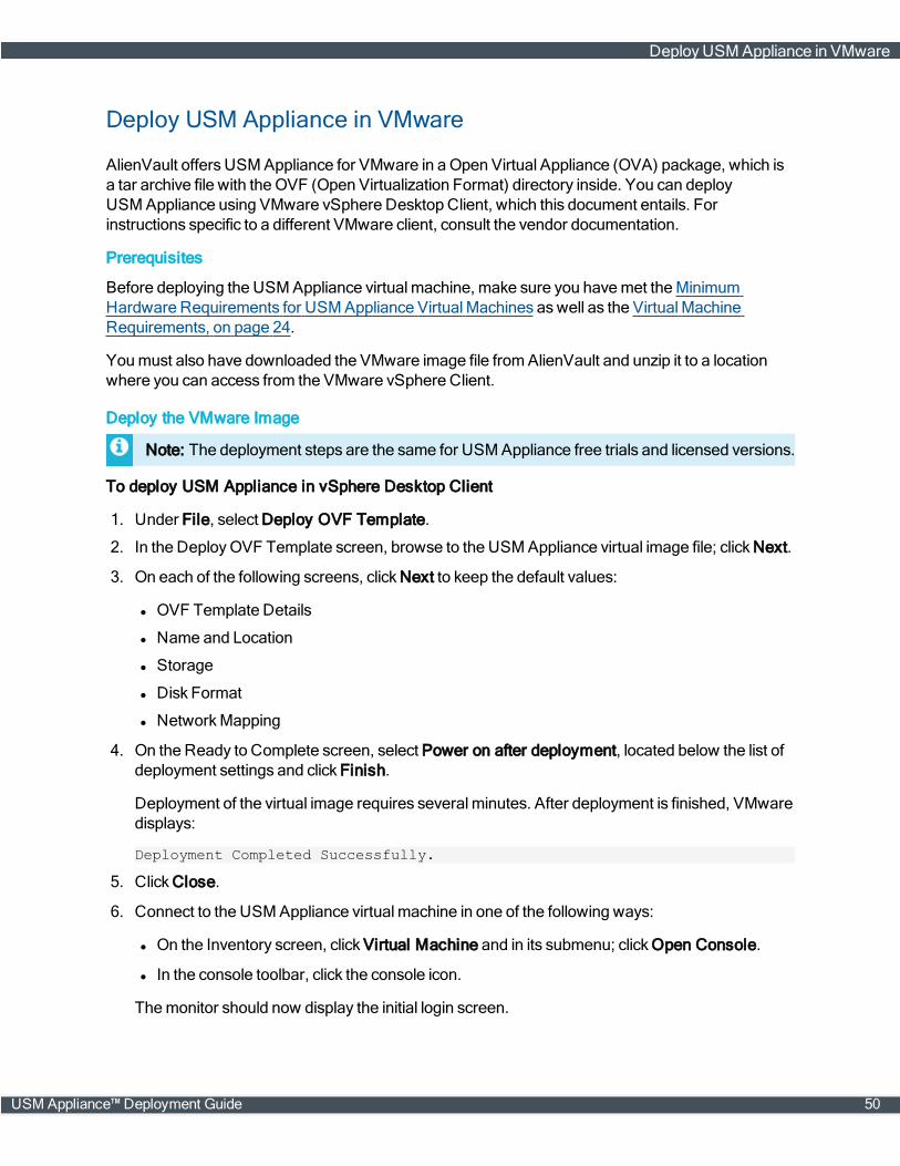
Deploy USM Appliance in VMware
AlienVault offers USM Appliance for VMware in a Open Virtual Appliance (OVA) package, which isa tar archive file with the OVF (Open Virtualization Format) directory inside. You can deployUSM Appliance using VMware vSphere Desktop Client, which this document entails. Forinstructions specific to a different VMware client, consult the vendor documentation.
Prerequisites
Before deploying the USM Appliance virtual machine, make sure you havemet theMinimumHardware Requirements for USM Appliance Virtual Machines aswell as the Virtual MachineRequirements, on page 24.
Youmust also have downloaded the VMware image file fromAlienVault and unzip it to a locationwhere you can access from the VMware vSphere Client.
Deploy the VMware Image
Note: The deployment steps are the same for USM Appliance free trials and licensed versions.
To deploy USM Appliance in vSphere Desktop Client
1. Under File, select Deploy OVF Template.
2. In the DeployOVF Template screen, browse to the USM Appliance virtual image file; click Next.
3. On each of the following screens, click Next to keep the default values:
l OVF Template Details
l Name and Location
l Storage
l Disk Format
l NetworkMapping
4. On the Ready to Complete screen, select Power on after deployment, located below the list ofdeployment settings and click Finish.
Deployment of the virtual image requires several minutes. After deployment is finished, VMwaredisplays:
Deployment Completed Successfully.
5. Click Close.
6. Connect to the USM Appliance virtual machine in one of the following ways:
l On the Inventory screen, click Virtual Machine and in its submenu; clickOpen Console.
l In the console toolbar, click the console icon.
Themonitor should now display the initial login screen.
DeployUSM Appliance in VMware
USM Appliance™ Deployment Guide 50
Note: Since USMAppliance Sensors do not have a webUI, you cannot access themthrough a browser. Follow Configure the USM Appliance Sensor after Deployment tofinish the configuration.
Monitor VMware Standard Virtual Switches
Note: For help on VMware vSphere Distributed Switches (VDS), see instructions fromVMware.
USM Appliance virtual machines have six network interfaces: one for management (eth0) and theother five for log collection and/or traffic capture on the network segment monitored. Connecting themonitoring interface(s) to a SPAN (Switched Port Analyzer) port, sometimes also called amirrorport, provides the following capabilities:
l Network IDS
l NetFlow and trafficmonitoring
l Passive asset identification
For USMAppliance tomonitor traffic from your physical network, you need to allocate a spare NIC(Network Interface Card) on your VMware server to pass the SPAN port traffic to the virtualnetwork. AlienVault recommends that you SPAN your internal firewall ports, connect the SPAN portto the spare NIC, and then associate the spare NIC with a vSwitch.
To monitor network traffic through a VMware vSwitch
1. Direct traffic from your physical network to the virtual network:
a. Enable port mirroring on the network you want USMAppliance tomonitor.
b. Allocate a spare NIC on your VMware server to receive themirrored traffic.
c. Associate your spare NIC with the vSwitch.
2. In the vSphere Desktop Client, click the Configuration tab and select Networking.
3. Locate the vSwitch you want USMAppliance tomonitor and click Properties.
4. Add a new port group to the existing switch:
DeployUSM Appliance in VMware
51 USM Appliance™ Deployment Guide
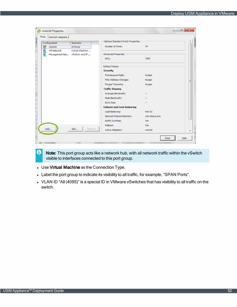
Note: This port group acts like a network hub, with all network traffic within the vSwitchvisible to interfaces connected to this port group.
l Use Virtual Machine as the Connection Type.
l Label the port group to indicate its visibility to all traffic, for example, “SPAN Ports”.
l VLAN ID “All (4095)” is a special ID in VMware vSwitches that has visibility to all traffic on theswitch.
DeployUSM Appliance in VMware
USM Appliance™ Deployment Guide 52
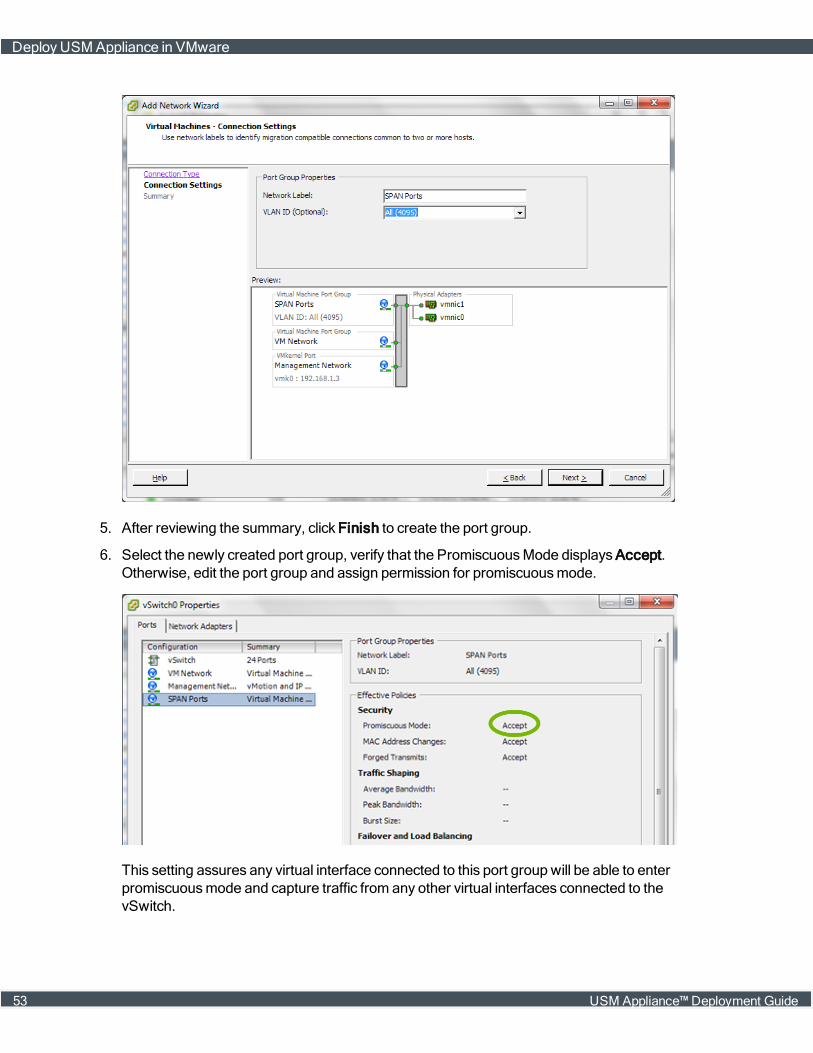
5. After reviewing the summary, click Finish to create the port group.
6. Select the newly created port group, verify that the PromiscuousMode displays Accept.Otherwise, edit the port group and assign permission for promiscuousmode.
This setting assures any virtual interface connected to this port group will be able to enterpromiscuousmode and capture traffic from any other virtual interfaces connected to thevSwitch.
DeployUSM Appliance in VMware
53 USM Appliance™ Deployment Guide

7. Now that the port group is created, you need to edit the USMAppliance node you havedeployed and connect one or more interfaces to the port group, "SPAN Ports", as shown in theexample below:
8. Lastly, you need to configure networkmonitoring in the AlienVault Console:
a. Connect to the AlienVault Console through SSH and use your credentials to log in.
The AlienVault Setupmenu displays.
b. Select Configure Sensor.
c. Select Configure Network Monitoring.
d. Use the keyboard arrow keys tomove to the interface assigned to the SPAN port group instep #7, select the interface by pressing the spacebar, and then press Enter (<OK>).
e. Press <Back> until you are on the AlienVault Setupmenu again; select Apply all Changes.
DeployUSM Appliance in VMware
USM Appliance™ Deployment Guide 54

f. Press <Yes> to confirm.
USMAppliance applies the changes and restarts all the services, whichmay take severalminutes.
Repeat the steps for every vSwitch you want to monitor.
Deploy USM Appliance Using Hyper-V Manager
Microsoft Hyper-V is a hypervisor that lets you create andmanage virtual machines by usingvirtualization technology built intoWindowsServers. Starting fromUSM Appliance version 5.3.4,AlienVault offers USM Appliance for Hyper-V in a Virtual Hard Disk (VHD) format, tested on thelatest version of the followingWindows operating systems:
l WindowsServer 2008 SP2
l WindowsServer 2008 R2 SP2
l WindowsServer 2012
l WindowsServer 2012 R2
l WindowsServer 2016
You can deployUSM Appliance usingMicrosoft Hyper-V Manager, an administrative tool formanaging local and remote Hyper-V hosts.
Prerequisites
The requirements for deploying USM Appliance in Hyper-V are the same as for the other virtualappliances that AlienVault supports. See Virtual Machine Requirements, on page 24 for details.However, to meet the requirements, youmust enable hyper-threading from the systemBIOS first.Refer to this virtualization blog post fromMicrosoft for explanation.
Youmust also have downloaded the Hyper-V image file fromAlienVault and unzip it to a locationwhere you can access from the Hyper-V Manager.
Note: Due to the size of the image file, the built-in zip utility onWindowsServer 2008 (allversions) cannot unzip the file. You can use 7-Zip or WinZip instead.
Create the Virtual Machine
To create a virtual machine using the Hyper-V Manager
1. Open the Hyper-V Manager.
2. In the Actions panel, click New > Virtual Machine.
The New Virtual Machine Wizard opens.
3. Go to Specify Name and Location and type a name for your new virtual machine:
DeployUSM Appliance Using Hyper-V Manager
55 USM Appliance™ Deployment Guide

4. Click Next.
5. ChooseGeneration 1 for this virtual machine and click Next.
6. Change the value of the Startup Memory:
l For USM Appliance Standard deployment options (including Standard Server, Standard Log-ger, and Standard Sensor), type 24576 MB.
l For USM Appliance All-in-One, type 16384 MB.
l For USM Appliance Remote Sensor, type 8192 MB.
7. Click Next.
8. Select the network adapter to the network you want to monitor and click Next.
9. Select Use an existing virtual hard disk and click Browse to locate the Hyper-V VHD file.
10. Click Next and on the summary page, click Finish.
DeployUSM Appliance Using Hyper-V Manager
USM Appliance™ Deployment Guide 56

Configure the Virtual Machine
To configure a virtual machine using the Hyper-V Manager
1. Select the USM Appliance virtual machine that you created and click Settings.
A new window opens.
2. Click Processor in the left panel,
l For USM Appliance All-in-One and USM Appliance Standard deployment options (includingStandard Server, Standard Logger, and Standard Sensor), select 8 number of virtual pro-cessors.
l For USM Appliance Remote Sensor, select 4 number of virtual processors
3. Click Apply.
4. Click Add Hardware > Network Adapter > Add to add network interfaces.
Note: USM Appliance All-in-One supports 6 network interfaces and USM ApplianceRemote Sensor supports 2 network interfaces. AlienVault recommends that you have atleast two network interfaces, one for management and the other for network IDS.
5. In Bandwidth Management, leave the option unchecked since enabling bandwidthmanagement introduces the risk of packet lost.
DeployUSM Appliance Using Hyper-V Manager
57 USM Appliance™ Deployment Guide
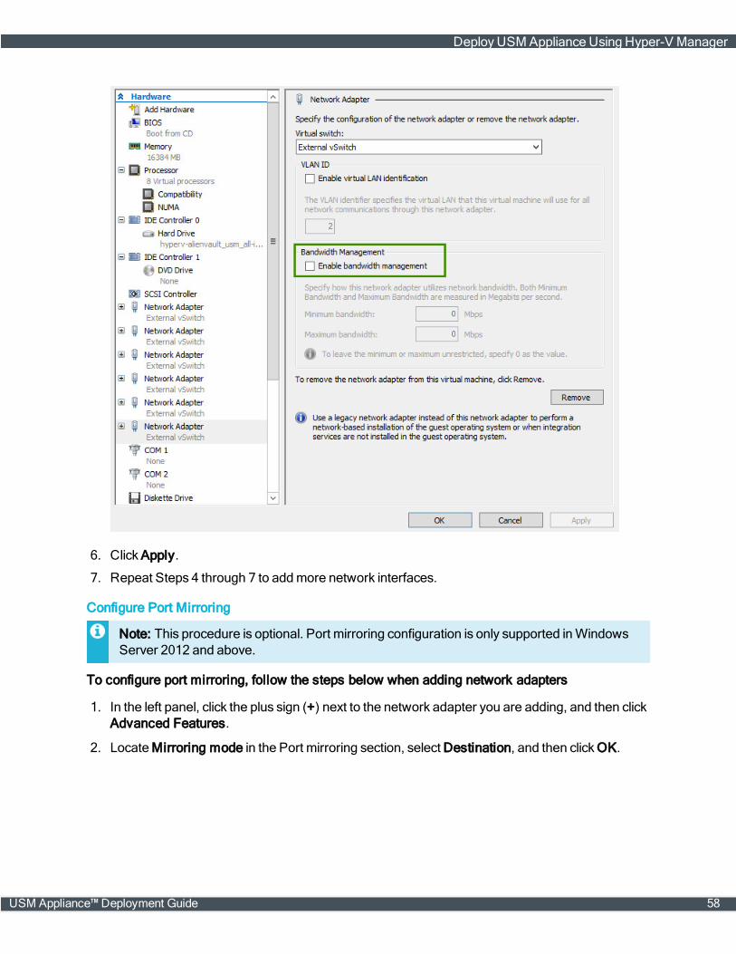
6. Click Apply.
7. Repeat Steps 4 through 7 to addmore network interfaces.
Configure Port Mirroring
Note: This procedure is optional. Port mirroring configuration is only supported inWindowsServer 2012 and above.
To configure port mirroring, follow the steps below when adding network adapters
1. In the left panel, click the plus sign (+) next to the network adapter you are adding, and then clickAdvanced Features.
2. LocateMirroring mode in the Port mirroring section, select Destination, and then clickOK.
DeployUSM Appliance Using Hyper-V Manager
USM Appliance™ Deployment Guide 58
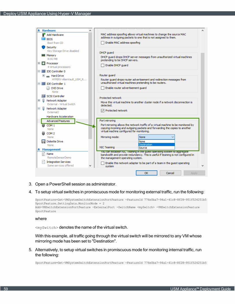
3. Open a PowerShell session as administrator.
4. To setup virtual switches in promiscuousmode for monitoring external traffic, run the following:
$portFeature=Get-VMSystemSwitchExtensionPortFeature -FeatureId 776e0ba7-94a1-41c8-8f28-951f524251b5$portFeature.SettingData.MonitorMode = 2Add-VMSwitchExtensionPortFeature -ExternalPort -SwitchName <mySwitch> -VMSwitchExtensionFeature$portFeature
where
<mySwitch> denotes the name of the virtual switch.
With this example, all traffic going through the virtual switch will bemirrored to any VMwhosemirroringmode has been set to "Destination".
5. Alternatively, to setup virtual switches in promiscuousmode for monitoring internal traffic, runthe following:
$portFeature=Get-VMSystemSwitchExtensionPortFeature -FeatureId 776e0ba7-94a1-41c8-8f28-951f524251b5
DeployUSM Appliance Using Hyper-V Manager
59 USM Appliance™ Deployment Guide

$portFeature.SettingData.MonitorMode = 2Add-VMSwitchExtensionPortFeature -ManagementOS -VMSwitchExtensionFeature $portFeature
Note: The -ManagementOS option does not allow you to specify a switch, so all virtualswitches, including the sharedmanagement NIC port, will be set in monitoringmode.
6. To setup virtual switches in promiscuousmode for monitoring both internal and external traffic,run the following:
$portFeature=Get-VMSystemSwitchExtensionPortFeature -FeatureId 776e0ba7-94a1-41c8-8f28-951f524251b5$portFeature.SettingData.MonitorMode = 2Add-VMSwitchExtensionPortFeature -ExternalPort -SwitchName <mySwitch> -VMSwitchExtensionFeature$portFeatureAdd-VMSwitchExtensionPortFeature -ManagementOS -VMSwitchExtensionFeature $portFeature
Note: In the steps above, MonitorMode 0 = None, 1 = Destination, and 2 = Source.
Start the Virtual Machine
To start the virtual machine using the Hyper-V Manager
1. Select your virtual machine and click Start on the right panel.
2. The system initialization screen appears and you will see the console to accessUSM Appliancefrom the command line.
Deploy USM Appliance with AMI
In this section, you will learn:
l Deploy the USM Appliance AMI, on page 61
l Connect to the AMI Through a Console, on page 62
Before You Start
After purchasing the USM Appliance AMI, youmust send your Amazon identifier and the region youwant the AMI deployed to AlienVault Support, who will use that information to share the privateUSM Appliance AMI with you.
Supported AWS regions:
l ap-northeast-1
l ap-northeast-2
l ap-south-1
l ap-southeast-1
l ap-southeast-2
l eu-central-1
l eu-west-1
DeployUSM Appliance with AMI
USM Appliance™ Deployment Guide 60

l us-east-1
l us-west-1
l us-west-2
Deploy the USM Appliance AMI
To deploy the AlienVault USM Appliance AMI
1. Sign in to your Amazon portal.
2. Click EC2.
3. Click Launch Instance.
4. ClickMy AMIs (on the navigation tree located on the left).
5. In the search field, enter "AlienVault_USM" and click Select.
6. Choose an Instance Type based on the following recommendation:
Image Name Recommended Instance Type
USM Appliance All-in-One m3.2xlarge (8 cores/30GB ) or c3.4xlarge (16 cores/30GB )
USM Appliance All-in-One Lite m3.2xlarge (8 cores/30GB ) or c3.4xlarge (16 cores/30GB )
USM Appliance Federation Server m3.2xlarge (8 cores/30GB ) or c3.4xlarge (16 cores/30GB )
USM Appliance Remote Sensor m3.xlarge (4 cores/15GB )
USM Appliance Remote Sensor Lite m3.xlarge (4 cores/15GB )
USM Appliance Standard Logger m3.2xlarge (8 cores/30GB ) or c3.4xlarge (16 cores/30GB )
USM Appliance Standard Server m3.2xlarge (8 cores/30GB ) or c3.4xlarge (16 cores/30GB )
USM Appliance Standard Sensor m3.2xlarge (8 cores/30GB ) or c3.4xlarge (16 cores/30GB )
Recommended Instance Type for the USM Appliance AMI
7. Click the square to the left of an instance, and then click Next: Configure Instance Details.
8. Select Launch as EBS-optimized instance to improve the disk performance.
9. Click Next: Add Storage.
10. Click Volume Type and choose "Provisioned IOPS". For optimal performance, set the IOPSvalue to "20000". See Amazon documentation for more details.
11. Click Next: Tag Instance.
12. In the Value field, type a name for your appliance, and then click Next: Configure SecurityGroup.
13. Click Add Rule to add HTTPS. This protocol allows Internet traffic to reach your USM Appliance
DeployUSM Appliance with AMI
61 USM Appliance™ Deployment Guide
instance.
Note: You do not need to add this rule if you are configuring a USM Appliance Sensor,which does not have a web interface.
14. (Optional) Click Add Rule to add HTTP. This protocol allowsweb traffic redirection to work inyour USM Appliance instance.
Note: You do not need to add this rule if you are configuring a USM Appliance Sensor,which does not have a web interface.
15. Click Review and Launch.
16. Review your configuration and click Launch.
17. Select Proceed without a key pair and I acknowledge that I have....
18. Click Launch Instances.
19. Click the instance launched.
The instance can have the following status checks:
Initializing. The image has not yet been deployed by Amazon.
1/2 checks. The image has been deployed, but it is not accessible. The image is still configuring.
2/2 checks. The image is ready and completely configured.
Note: Wait a few minutes before trying to log in for the first time. The databasemay needmoretime to finish initializing. If you try to log in before, youmay see a Database Connection error inthe browser.
Connect to the AMI Through a Console
To access the AMI through a console
1. Open a terminal and enter the following command:
SSH root@<publicDNS>
where
<publicDNS> refers to the default DNS assigned to AlienVault USM Appliance.
2. Login to the system.
The default credential is root/alienvault.
3. After logging in for the first time, the systemwill request a password change.
DeployUSM Appliance with AMI
USM Appliance™ Deployment Guide 62

Configure the USM Appliance Sensor after Deployment
You'll want to set up and configure the USMAppliance Server first. If you purchased USM ApplianceStandard, Enterprise, or Remote Sensors, next you will want to configure the sensor by providingthe USM Appliance Server IP address and Framework IP address through the AlienVault Setupmenu. Then, there are some final configuration steps on the webUI.
Prerequisites
l USM Appliance All-in-One — Youmust have already configured the USM Appliance All-in-Onebefore you can complete the sensor configuration.
l USM Appliance Standard or Enterprise — Youmust have already configured theUSM Appliance Server and have its IP address available.
l If you intend to configure VPN in your USM Appliance deployment, youmust set up a VPN tunnelfor the client beforehand. This provides you with a VPN IP address that you use in this con-figuration task. For details, see About Configuring a Virtual Private Network, on page 147.
Configure the USM Appliance Sensor
To configure a sensor on USM Appliance All-in-One or USM Appliance Server
1. Connect to the AlienVault Console through SSH and use your credentials to log in.
The AlienVault Setupmenu displays.
2. Select Configure Sensor.
3. Select Configure AlienVault Server IP.
4. Type the IP address of the USM Appliance Server the sensor should contact and press Enter(<OK>).
Important: If this USM Appliance deployment will use VPN, substitute the VPN IP for thephysical IP address.
The Configure Sensor menu appears again.
5. Select Configure AlienVault Framework IP.
6. Type the same IP address you did for the server and press Enter (<OK>).
The application returns you to the Configure Sensor menu.
7. Press <Back> until you are on the AlienVault Setupmenu again; select Apply all Changes.
8. Press <Yes> to confirm.
Configure the USM Appliance Sensor after Deployment
63 USM Appliance™ Deployment Guide
USMAppliance applies the changes and restarts all the services, whichmay take severalminutes.
9. Launch the USMAppliance webUI and log in as administrator.
10. Navigate to Configuration > Deployment > Components > Sensors.
A warningmessage appears, stating:
The following sensors are being reported as enabled by the server,but are not configured.
Thewarningmessage contains the sensor IP address and two links labeled Insert and Discard.
11. Click Insert.
A new screen containing a form appears. To answer themonitor network question, see AboutCorrelation Contexts for assistance.
12. Fill out the form and click Save.
13. Repeat all of the foregoing procedures for every sensor you plan to deploy in your network.
Configure the USM Appliance Logger after Deployment
Youwill need to configure the USM Appliance Logger if you are deploying one of the following:
l USM Appliance Standard or Enterprise solution
l Using USM Appliance All-in-One, but deploying one or more additional USM Appliance Loggersto the one that comeswith the All-in-One
Unlike the Standard/Enterprise USM Appliance Server and Sensors, the USM Appliance Loggercan only be configured through the USM Appliance webUI.
Note: If you want to configure high availability in a USM Appliance Standard or Enterprisedeployment, do not complete this logger configuration task until after you have completed HAconfiguration of your two USM Appliance Logger nodes. See Configuring High Availability forUSM Appliance Standard Loggers , on page 169.
Prerequisites
l Youmust have already deployed the USMAppliance Server and USM Appliance Logger, andcompleted the initial setup tasks.
l If you intend to configure VPN in your USM Appliance deployment, youmust set up the VPN tun-nel beforehand. This provides you with a VPN IP address that you use in this configuration task.For details, see About Configuring a Virtual Private Network, on page 147.
Configure the USM Appliance Logger after Deployment
USM Appliance™ Deployment Guide 64
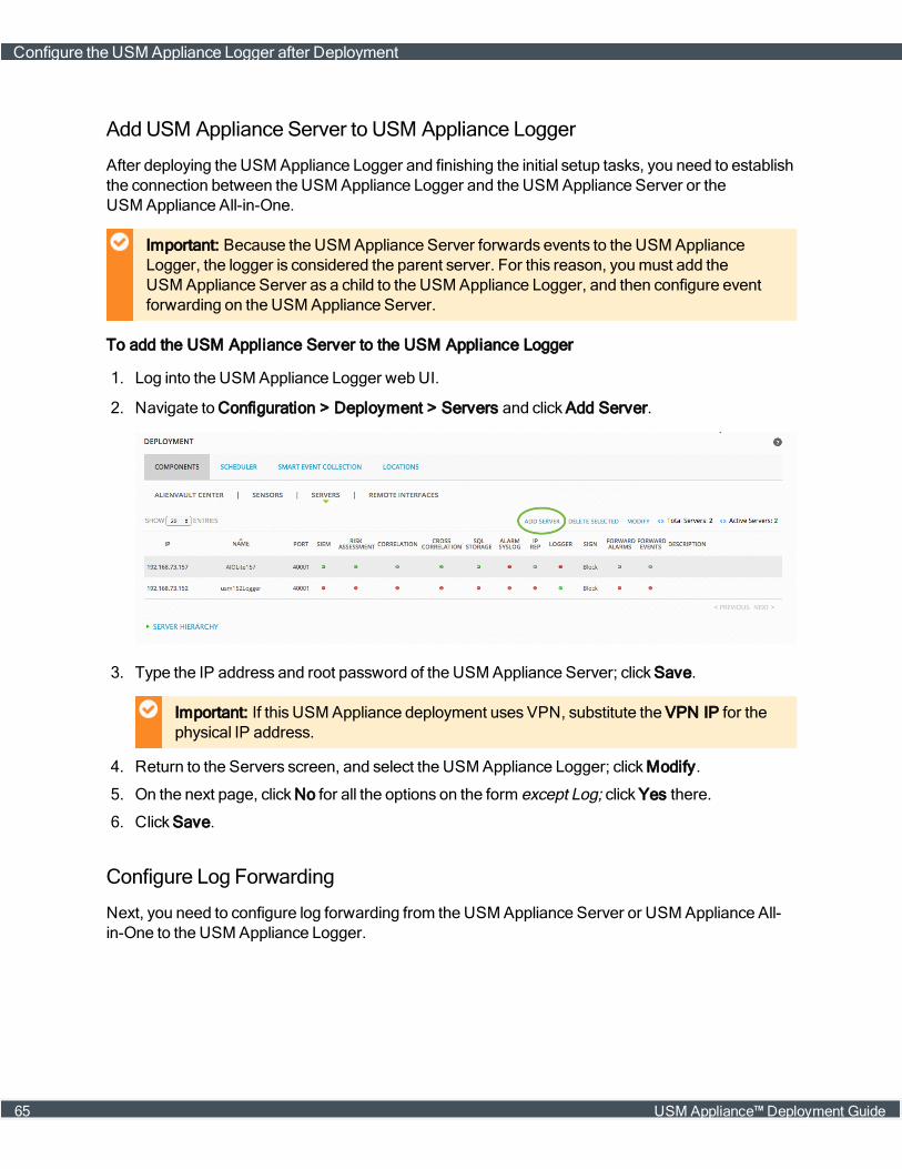
AddUSM Appliance Server to USM Appliance Logger
After deploying the USM Appliance Logger and finishing the initial setup tasks, you need to establishthe connection between the USM Appliance Logger and the USM Appliance Server or theUSM Appliance All-in-One.
Important: Because the USM Appliance Server forwards events to the USM ApplianceLogger, the logger is considered the parent server. For this reason, youmust add theUSM Appliance Server as a child to the USM Appliance Logger, and then configure eventforwarding on the USM Appliance Server.
To add the USM Appliance Server to the USM Appliance Logger
1. Log into the USM Appliance Logger web UI.
2. Navigate to Configuration > Deployment > Servers and click Add Server.
3. Type the IP address and root password of the USM Appliance Server; click Save.
Important: If this USM Appliance deployment uses VPN, substitute the VPN IP for thephysical IP address.
4. Return to the Servers screen, and select the USM Appliance Logger; clickModify.
5. On the next page, click No for all the options on the form except Log; click Yes there.
6. Click Save.
Configure Log Forwarding
Next, you need to configure log forwarding from the USM Appliance Server or USM Appliance All-in-One to the USM Appliance Logger.
Configure the USM Appliance Logger after Deployment
65 USM Appliance™ Deployment Guide
To configure log forwarding
1. Log into the USM Appliance Server web UI.
2. Go to Configuration > Deployment > Servers.
You should now see both the USM Appliance Server and the USM Appliance Logger listed.
3. Select the USM Appliance Logger and clickModify.
4. On the next page, type the credentials for the Remote Admin User and the Remote Password.
These are the admin user credentials to log into the Logger.
5. To populate the remote URL field automatically, click anywhere within the field.
6. Click Set Remote Logger.
7. Return to the Servers page, select the USM Appliance Server and clickModify.
8. Set the option for Log to No.
9. In the Forward Servers section of the page, click Add Server.
This extends the form and displays a list box labeled Server.
10. Select the USM Appliance Logger and click Add New.
The Logger and its IP address should now appear in the Server field.
11. Click Save.
12. Return to the Servers page, click Apply Changes.
13. To verify that you added the USM Appliance Logger successfully, click Server Hierarchy.
You should now see that there is an arrow extending from the USM Appliance Server to theUSM Appliance Logger, where previously theywere each floating freely in the graph.
14. The Logger becomes active immediately. To view Logger activity, go to Analysis > Raw Logs.
Configure the USM Appliance Logger after Deployment
USM Appliance™ Deployment Guide 66
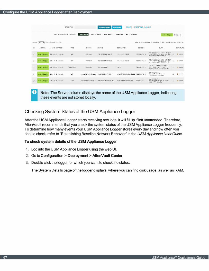
Note: The Server column displays the name of the USM Appliance Logger, indicatingthese events are not stored locally.
Checking System Status of the USM Appliance Logger
After the USM Appliance Logger starts receiving raw logs, it will fill up if left unattended. Therefore,AlienVault recommends that you check the system status of the USM Appliance Logger frequently.To determine how many events your USM Appliance Logger stores every day and how often youshould check, refer to "Establishing Baseline Network Behavior" in the USMAppliance User Guide.
To check system details of the USM Appliance Logger
1. Log into the USM Appliance Logger using the webUI.
2. Go to Configuration > Deployment > AlienVault Center.
3. Double click the logger for which you want to check the status.
The SystemDetails page of the logger displays, where you can find disk usage, aswell as RAM,
Configure the USM Appliance Logger after Deployment
67 USM Appliance™ Deployment Guide
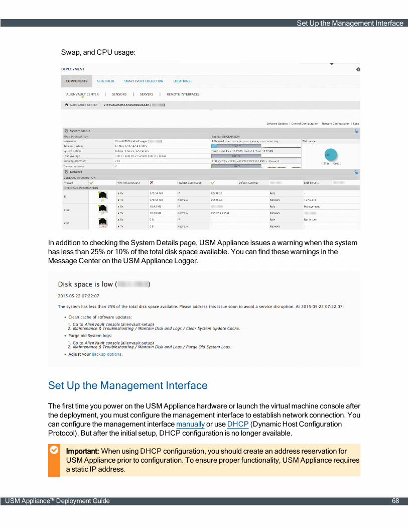
Swap, and CPU usage:
In addition to checking the SystemDetails page, USM Appliance issues a warning when the systemhas less than 25% or 10% of the total disk space available. You can find these warnings in theMessage Center on the USM Appliance Logger.
Set Up the Management Interface
The first time you power on the USMAppliance hardware or launch the virtual machine console afterthe deployment, youmust configure themanagement interface to establish network connection. Youcan configure themanagement interfacemanually or use DHCP (Dynamic Host ConfigurationProtocol). But after the initial setup, DHCP configuration is no longer available.
Important: When using DHCP configuration, you should create an address reservation forUSMAppliance prior to configuration. To ensure proper functionality, USMAppliance requiresa static IP address.
Set Up theManagement Interface
USM Appliance™ Deployment Guide 68
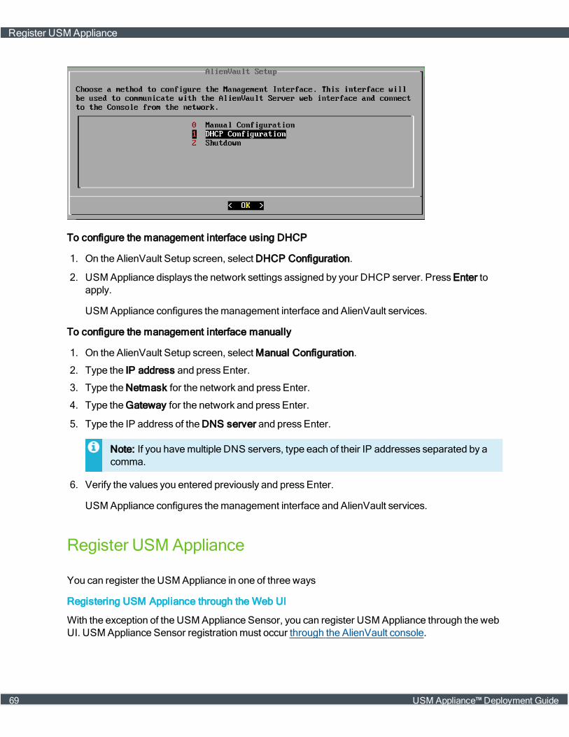
To configure the management interface using DHCP
1. On the AlienVault Setup screen, select DHCP Configuration.
2. USMAppliance displays the network settings assigned by your DHCP server. Press Enter toapply.
USMAppliance configures themanagement interface and AlienVault services.
To configure the management interface manually
1. On the AlienVault Setup screen, select Manual Configuration.
2. Type the IP address and press Enter.
3. Type the Netmask for the network and press Enter.
4. Type theGateway for the network and press Enter.
5. Type the IP address of the DNS server and press Enter.
Note: If you havemultiple DNS servers, type each of their IP addresses separated by acomma.
6. Verify the values you entered previously and press Enter.
USMAppliance configures themanagement interface and AlienVault services.
Register USM Appliance
You can register the USMAppliance in one of three ways
Registering USM Appliance through the Web UI
With the exception of the USM Appliance Sensor, you can register USM Appliance through the webUI. USM Appliance Sensor registrationmust occur through the AlienVault console.
Register USMAppliance
69 USM Appliance™ Deployment Guide

Prerequisites for Registration
l The appliancemust have a connection to the Internet.
l Youmust have the USM Appliance license key issued by AlienVault.
To register through the web UI
1. Open a web browser and type the USMAppliance IP address into the address bar.
The AlienVault Free Trial Activation screen appears.
2. Click click here to enter your product license key.
3. On the welcome screen, type the license key in the Product License Key field and click Send.
An information box displays telling you that AlienVaultUSM Appliance activated successfully.
4. Click Finish.
TheWelcome screen appears and contains a form that youmust fill out to create the defaultadmin account for the webUI. See Create the Default Admin User for details.
Registering USM Appliance from the AlienVault Console
USM Appliance Sensor registrationmust occur through the AlienVault console. You can registerother USMAppliance from the console aswell.
Prerequisites for Registration
l The appliancemust have a connection to the Internet.
l Youmust have the USM Appliance license key issued by AlienVault.
To register through the AlienVault console
1. Log into the AlienVault console.
The AlienVault Setupmenu appears.
“Register this Appliance” is now the default selection.
2. Press Enter to register.
3. On theOnline Registration screen, tab to Online registration and press Enter.
4. Type the license key, then press Enter.
The registration process can take several seconds. A statusmessage displays a registrationprogress bar.
5. When registration has completed, message box displays:
AlienVault USM Appliance activated successfully.
Register USMAppliance
USM Appliance™ Deployment Guide 70

6. To continue, press Enter.
The AlienVault Setupmenu appears again, but this time without the Register this Appliancemenu option.
Registering USM Appliance Offline
AlienVault recommends that you register USM Appliance using one of the onlinemethods becauseit is easier and faster. However, if you do not have access to the Internet or you are in a confinedenvironment, you can also register USM Appliance offline.
Prerequisites for Offline Registration
To register the appliance offline youmust have the following:
l A license key file called alienvault-license.deb specific to each USMAppliance instance,obtained fromAlienVault Technical Support.
Before AlienVault Support can generate and send you the license key file, youmust first send themthe system_id of each USM Appliance system that you want to register.
To find the system_id of your USM Appliance system
1.
Connect to the AlienVault Console through SSH and use your credentials to log in.
The AlienVault Setupmenu displays.
2. Select About this Installation and press Enter.
3. Copy the system_id from the screen and send it to AlienVault Technical Support.
Registering USM ApplianceOffline
To register offline using a USB flash drive
1. Save the license file you received fromAlienVault, alienvault-license.deb, to a computerdesktop or other location where you can easily retrieve it.
2. Insert a FAT32-formatted USB flash drive into the same computer, and then copy the license fileto the root directory of the formatted USB flash drive.
3. Connect to USM Appliance through SSH.
The AlienVault Setupmenu appears with "Register this Appliance" as the default selection.
4. Press Enter to register.
5. Select Offline registration.
6. Connect the flash drive to the USB port of themachine and press Enter (<OK>).
Your systemwill be registered after this process completes successfully.
Register USMAppliance
71 USM Appliance™ Deployment Guide
Alternatively, you can choose to register USMAppliance offline without using the USB flash drive.
To register offline without a USB flash drive
1. Save the license file you received fromAlienVault, alienvault-license.deb, to a computerdesktop or other location where you can easily retrieve it.
2. Transfer the license file to USMAppliance directly using SCP.
For example, use the command below to copy alienvault-license.deb to the /rootdirectory in USMAppliance
scp alienvault-license.deb root@<USM-Appliance-IP-address>:/root/
Youwill be prompted to enter the password for the root user of the USMAppliance instance.
3. Connect to USM Appliance through SSH.
4. On the AlienVault Setupmainmenu, select Jailbreak System to gain command line access.
Select Yes when prompted. You will be in the root directory.
5. Run the following command from the root directory, where the alienvault-license.deb fileexists
dpkg -i alienvault-license.deb
Your systemwill be registered after this process completes successfully.
Register USMAppliance
USM Appliance™ Deployment Guide 72

USMAppliance Initial Setup
Before performing the setup tasks, youmust have successfully deployed USMAppliance and SetUp theManagement Interface.
Topics covered in this section include the following:
Access the AlienVault SetupMenu 74
Configure Network Interfaces 76
Configure the Search Domain 79
Configure a Hostname for USMAppliance 79
Change the Default Time Zone 80
Configure Synchronization with an NTP Server 81
Configure USM Appliance to Recognize Your Local Keyboard 81
Configure CustomHTTPS Certificates in USMAppliance 82
Create the Default Admin User 83
ConfigureMail Relay in USM Appliance 85
USM Appliance™ Deployment Guide 73

Access the AlienVault Setup Menu
You can access the AlienVault Setupmenu in one of the following ways:
l Local Management — By using amonitor, keyboard, andmouse connected directly to theUSM Appliance hardware.
l Virtual Management — Virtual Appliance users access the console as a vSphere client orthrough an SSH client such as PuTTY.
l Remote Management — After IPMI or HPE iLO configuration, you can access the console by anycomputer connected to the same subnet in which the appliance runs, through the remote con-nection.
For procedural simplicity, the following task steps reference the user interface (UI) of the SSH clientPuTTY asmeans to explain how to access the AlienVault console.
To access the AlienVault console
1. Launch PuTTY or any other SSH client, and in the Host Name (or IP address) field, type the IPaddress of the appliance.
2. Make sure that SSH is selected.
This is usually the default setting.
3. ClickOpen.
4. Enter the user credentials you use to log into the SSH client.
The AlienVault splash screen for USM Appliance appears. If this is the first time, it displays theroot username and a randomly generated password for you to enter.
Access the AlienVault SetupMenu
74 USM Appliance™ Deployment Guide
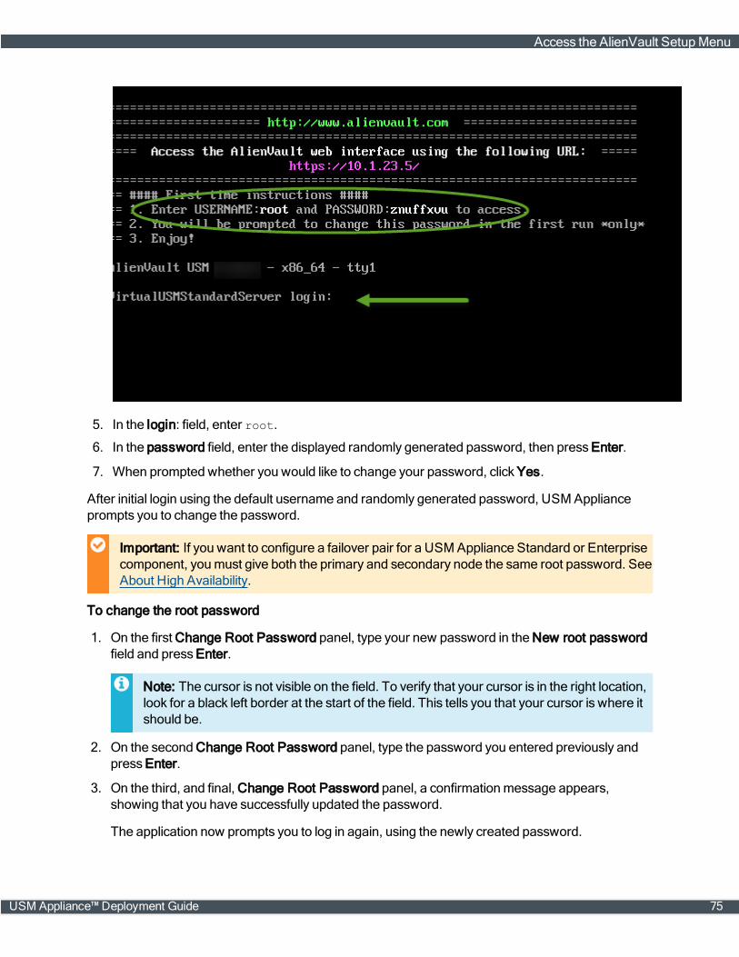
5. In the login: field, enter root.
6. In the password field, enter the displayed randomly generated password, then press Enter.
7. When prompted whether you would like to change your password, click Yes.
After initial login using the default username and randomly generated password, USM Applianceprompts you to change the password.
Important: If you want to configure a failover pair for a USM Appliance Standard or Enterprisecomponent, youmust give both the primary and secondary node the same root password. SeeAbout High Availability.
To change the root password
1. On the first Change Root Password panel, type your new password in the New root passwordfield and press Enter.
Note: The cursor is not visible on the field. To verify that your cursor is in the right location,look for a black left border at the start of the field. This tells you that your cursor is where itshould be.
2. On the second Change Root Password panel, type the password you entered previously andpress Enter.
3. On the third, and final, Change Root Password panel, a confirmationmessage appears,showing that you have successfully updated the password.
The application now prompts you to log in again, using the newly created password.
Access the AlienVault SetupMenu
USM Appliance™ Deployment Guide 75
Configure Network Interfaces
USM Appliance All-in-One comeswith six network interfaces, numbered eth0 to eth5.USM Appliance uses these interfaces to perform the following functions:
l Connect to the Internet
l Monitor the network, using its built-in IDS capabilities
l Run asset scans
l Collect log data from your assets
l Run vulnerability scans
l Generate network flows
Based on functionality, you can classify the interfaces into the following categories:
Management
By default, USM Appliance uses themanagement interface to perform networkmonitoring, logcollection, and scanning. So, for this reason, you do not need to configure any additional interfaces,as long as they are all on the same subnet as themanagement interface.
Themanagement interface lets you communicate with the AlienVault console, as well as connect tothe webUI.
Note: The default port for themanagement interface is eth0. However, youmay configure adifferent port for this interface, if desired.
Network Monitoring
When the administrator configures an interface for networkmonitoring, the interface operates inpassive listeningmode (also known as promiscuousmode). A network tap or span is set up thatallows the interface tomonitor all packet traffic passing through it for threats.
Because USM Appliance's built-in IDS capability uses the networkmonitoring interface, youmustdedicate at least one of the network interfaces to it.
Log Collection and Scanning
You use the Log Collection and Scanning interface to reach the networks and systems fromwhichyou want to collect data. You also use it to scan the systems, using USM Appliance's built-in assetdiscovery, vulnerability assessment, and availabilitymonitoring tools.
Setting up this interface requires assignment of an IP address and networkmask to the interface.
Not in Use
This is the default option for all the interfaces except themanagement interface. It applies to anynetwork interface that is not in use and not configured.
Configure Network Interfaces
76 USM Appliance™ Deployment Guide
UpdateManagement Interface Configuration
Youmust configure themanagement interface immediately after deploying the USMAppliancevirtual machine or the first time when you power on the USMAppliance hardware. See Set Up theManagement Interface for details.
If you need tomodify themanagement interface configuration, follow the steps below.
1. Connect to the AlienVault Console through SSH and use your credentials to log in.
The AlienVault Setupmenu displays.
2. Select System Preferences.
3. Select Configure Network.
4. Select Setup Management Network.
5. Use the keyboard arrow keys tomove to the interface, select the interface by pressing the space-bar, and then press Enter (<OK>).
6. Type the IP address and press Enter.
7. Type the Netmask for the network and press Enter.
8. Type theGateway for the network and press Enter.
9. Press <Back> until you are on the AlienVault Setupmenu again; select Apply all Changes.
10. Press <Yes> to confirm.
USMAppliance applies the changes and restarts all the services, whichmay take severalminutes.
Configure Additional Network Interfaces
In addition to providing network connection, themanagement interface on USMAppliance can alsomonitor your network and collect logs from your assets. But if you want to use a different interfacewith a different IP address to perform those functions, youmust configure those interfacesseparately.
To set up additional network interface
1. Connect to the AlienVault Console through SSH and use your credentials to log in.
The AlienVault Setupmenu displays.
2. Select System Preferences.
3. Select Configure Network.
4. Select Setup Network Interface.
5. Use the keyboard arrow keys tomove to the interface, select the interface by pressing the space-bar, and then press Enter (<OK>).
Configure Network Interfaces
USM Appliance™ Deployment Guide 77

6. Type the IP address and press Enter.
7. Type the Netmask for the network and press Enter.
8. Press <Back> until you are on the AlienVault Setupmenu again; select Apply all Changes.
9. Press <Yes> to confirm.
USMAppliance applies the changes and restarts all the services, whichmay take severalminutes.
Enable Additional Listening Interfaces
If you want to use different interfaces tomonitor network traffic but do not want to assignIP addresses to them, you can enable them in promiscuousmode.
To enable additional listening interfaces on USM Appliance All-in-One or USM ApplianceSensor
1. Connect to the AlienVault Console through SSH and use your credentials to log in.
The AlienVault Setupmenu displays.
2. Select Configure Sensor.
3. Select Configure Network Monitoring.
4. Use the keyboard arrow keys tomove to the interface, select the interface by pressing thespacebar, and then press Enter (<OK>).
5. Press <Back> until you are on the AlienVault Setupmenu again; select Apply all Changes.
6. Press <Yes> to confirm.
USMAppliance applies the changes and restarts all the services, whichmay take severalminutes.
Configure Network Interfaces
78 USM Appliance™ Deployment Guide

Configure the Search Domain
For DNS (Domain NameSystem) lookup and reverse DNS resolution to work correctly, USMAppliance requires that you configure the search domain after you have completed the deployment.
To configure the search domain in USM Appliance
1. Connect to the AlienVault Console through SSH and use your credentials to log in.
The AlienVault Setupmenu displays.
2. Select System Preferences.
3. Select Configure Network.
4. Select Network Domain.
5. Type the domain name of your network and press Enter. The default is alienvault.
Important: You can only enter ONE domain in this field.
6. Press Enter to continue.
7. Press <Back> until you are on the AlienVault Setupmenu again; select Apply all Changes.
8. Press <Yes> to confirm.
USMAppliance applies the changes and restarts all the services, whichmay take severalminutes.
9. Return to the AlienVault Setupmainmenu and select Reboot Appliance.
Configure a Hostname for USM Appliance
You should always configure a hostname for USM Appliance. This helps you identify each oneuniquely, which is particularly important if you need to contact AlienVault Support for technicalassistance.
Your PCI DSS 3.1 compliance audit will fail when a certificate whose CommonName (CN) orwhose entries in the X509 Subject Alternative Name do not match the Fully Qualified Domain Name(FQDN) of the system in AlienVault USM Appliance.
Certificates, whose CN is not equal to the FQDN, cannot be verified through a Public KeyInfrastructure (PKI). A service using such a certificate cannot authenticate itself towards a user,unless the user can determine its trustworthiness through another channel. If there is no additionalchannel available, a user cannot distinguish between a genuine and a forged certificate, whichbenefits theman-in-the-middle attack.
Therefore, AlienVault recommends that you use the FQDN when naming USM Appliance and toalso use this FQDN as the CN or as X509 Subject Alternative Name (type DNS) to reduce the risk ofman-in-the-middle attacks and to avoid failure in PCI compliance audits.
Configure the Search Domain
USM Appliance™ Deployment Guide 79
To configure a hostname for USM Appliance
1. Connect to the AlienVault Console through SSH and use your credentials to log in.
The AlienVault Setupmenu displays.
2. Select System Preferences.
3. Select Configure Hostname.
4. Type the name for this host and press Enter.
Note: Any name you choosemust not have spaces in it. For guidance on choosing aname, see RFC 1178.
5. Press Enter to continue.
6. Press <Back> until you are on the AlienVault Setupmenu again; select Apply all Changes.
7. Press <Yes> to confirm.
USMAppliance applies the changes and restarts all the services, whichmay take severalminutes.
8. Return to the AlienVault Setupmainmenu and select Reboot Appliance.
Change the Default Time Zone
The default time zone for USMAppliance is Pacific Time (UTC -7h). If you are not operating in thattime zone, youmust change it. Otherwise, USM Appliance does not accurately timestamp events.
To change the default time zone
1. Connect to the AlienVault Console through SSH and use your credentials to log in.
The AlienVault Setupmenu displays.
2. Select System Preferences.
3. Select Change Location.
4. Select Date and Time.
5. Select Configure Time Zone.
An information panel advises you that the time zone, aswell as your profile and themysqlservices, will be changed.
6. Press Enter to confirm.
The Package Configuration panel appears, where America is the default setting.
7. Locate the applicable region or continent for your location.
8. Press <Back> until you are on the AlienVault Setupmenu again; select Apply all Changes.
Change the Default Time Zone
80 USM Appliance™ Deployment Guide
9. Press <Yes> to confirm.
USMAppliance applies the changes and restarts all the services, whichmay take severalminutes.
Configure Synchronization with an NTP Server
Use of an NTP server in your network helps ensure that all system components are correctlysynchronized. This is particularly important for timestamp accuracy and auditability in your efforts tocomply with certain regulatory standards.
If you plan to configure failover in a USM Appliance Standard or Enterprise deployment youmust setup one NTP server for your primary nodes and another for your secondary nodes, and synchronizeeach node to its respective NTP server. See About High Availability, on page 157.
Important: The NTP server requires use of port 123 over UDP.
To enable or disable synchronization with an NTP server
1. Connect to the AlienVault Console through SSH and use your credentials to log in.
The AlienVault Setupmenu displays.
2. Select System Preferences.
3. Select Change Location.
4. Select Date and Time.
5. Select Configure NTP Server.
6. Select Enable by pressing the spacebar, and then press Enter (<OK>).
7. Type the hostname or IP address of the NTP Server.
The application returns you to the Date and Timemenu.
8. Press <Back> until you are on the AlienVault Setupmenu again; select Apply all Changes.
9. Press <Yes> to confirm.
USMAppliance applies the changes and restarts all the services, whichmay take severalminutes.
Configure USM Appliance to Recognize Your Local Keyboard
Follow this procedure if your keyboard does not use a United States key layout.
Configure Synchronization with an NTP Server
USM Appliance™ Deployment Guide 81
To change the default keyboard layout
1. Connect to the AlienVault Console through SSH and use your credentials to log in.
The AlienVault Setupmenu displays.
2. Select System Preferences.
3. Select Change Location.
4. Select Configure Keyboard.
5. Use the keyboard arrow keys to scroll the list and find your selection, and then press Enter<Ok>.
You will be able to select the Keyboardmodel, Keyboard layout, Key to function as AltGr, andCompose key.
6. Press <Back> until you are on the AlienVault Setupmenu again; select Apply all Changes.
7. Press <Yes> to confirm.
USMAppliance applies the changes and restarts all the services, whichmay take severalminutes.
Configure Custom HTTPS Certificates in USM Appliance
You can secure your USM Appliance by providing your own SSL certificates, and you can configurethe certificates through the webUI.
To configure a custom HTTPS certificate in USM Appliance
1. Log into the USMAppliance webUI and go to Configuration > Administration > Main.
2. Extend USM Framework.
3. Click the Browse button to upload your customweb server SSL certificate and private key filesin PEM (Privacy EnhancedMail) format:
Configure CustomHTTPS Certificates in USMAppliance
82 USM Appliance™ Deployment Guide

Important: Make sure that your certificate file includes both the "begin" and "end" lines.
4. (Optional) If your SSL certificate requires any intermediate certificates, upload it inWeb ServerSSL CA Certificates (PEM format).
If you need help generating a certificate, see How to Generate a Certificate Signing Request forUSM Appliance.
Create the Default Admin User
When you connect to the USM Appliance webUI for the first time after installation and setup,USM Appliance prompts you to create the default admin user.
After you create the default admin, you can log in and use USM Appliance.
Create the Default Admin User
USM Appliance™ Deployment Guide 83

To create the default admin
1. Access the USM Appliance webUI.
TheWelcome screen appears when you access the webUI for the first time.
2. Fill out the form.
Note: The option Share anonymous usage statistics and system information to help usmake USM Appliance better enables telemetry. For information about this, see the KB articleWhat Is Telemetry Collection and How Does It Work.
3. When you finish filling out the form, click Start Using AlienVault.
4. Type the admin username and password you created in the form, then click Login.
If you plan to havemultiple administrators to help administer USM Appliance, you should create oneor more admin users.
For instructions to create additional administrators locally on USM Appliance, see "Creating NewAccounts for Local Users" or to create additional administrators using LDAP, see "Creating NewAccounts for LDAP Users" under User Administration in the USM Appliance User Guide.
Create the Default Admin User
84 USM Appliance™ Deployment Guide

Configure Mail Relay in USM Appliance
You can configure to receive emails fromUSM Appliance, for example, when an alarm appears or areport finishes running. USM Appliance uses Postfix, an open-sourcemail transfer agent (MTA), asSMTP (SimpleMail Transfer Protocol) Server for outgoingmessages.
Protocol PortNumber Notes
SMTP 25 This is the port number assigned to SMTP and used for mail server relay. Notethat most Internet service providers (ISPs) block this port to curb the amount ofspam they receive.
TLS(TransportLayerSecurity)
587 This is the default port number that USM Appliance uses to send outgoingmessages. The connection is encrypted by executing the STARTTLS command.
SSL(SecureSocketsLayer)
465 The Internet Assigned Numbers Authority originally registered 465 for SMTPS(Simple Mail Transfer Protocol Secure), a deprecated method for securing SMTP.Port 465 is now registered for SSM (Source-Specific Multicast), but ISPs maintainport 465 because some legacy systems do not support STARTTLS. Therefore,USM Appliance supports SSL connection through port 465.
USM Appliance SMTP Server Default Settings
USM Appliance also enables the following properties fromPostfix:
smtp_sasl_auth_enable = yessmtp_sasl_security_options = noanonymoussmtp_sasl_tls_security_options = noanonymous
ThismeansUSM Appliance enables SASL (Simple Authentication and Security Layer )authentication for SMTP, denying anonymous authentication.
Mail Server Relay Configuration
For simply receiving emails fromUSM Appliance, you do not need to set upmail server relay.However, if your company has a dedicatedmail server that you want to keep using, you canconfigure USM Appliance to route emails through your corporatemail program. To prevent suchmessages from going to your junkmail or spam folder, you can add USM Appliance as a safe senderfor Office 365 or add it to the email whitelist for Gmail.
You perform this task on either a USM Appliance All-in-One or a USM Appliance Server.
To configure mail server relay on USM Appliance
1. Login to the USM Appliance webUI, and then go to Configuration > Deployment.
2. Under AlienVault Components Information, click the SystemDetails icon ( ) of the systemyou want to change.
3. On the next page, clickGeneral Configuration, located top-right above the SystemStatus.
ConfigureMail Relay in USM Appliance
USM Appliance™ Deployment Guide 85
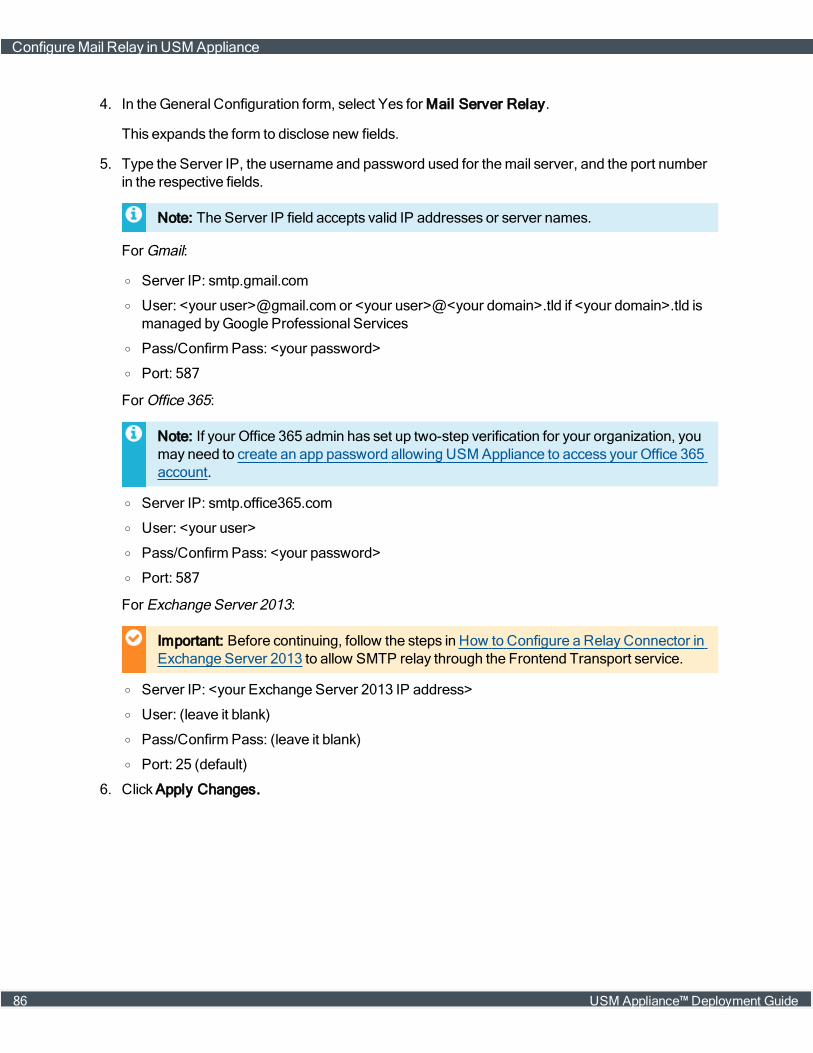
4. In the General Configuration form, select Yes for Mail Server Relay.
This expands the form to disclose new fields.
5. Type the Server IP, the username and password used for themail server, and the port numberin the respective fields.
Note: The Server IP field accepts valid IP addresses or server names.
For Gmail:
o Server IP: smtp.gmail.com
o User: <your user>@gmail.com or <your user>@<your domain>.tld if <your domain>.tld ismanaged byGoogle Professional Services
o Pass/Confirm Pass: <your password>
o Port: 587
For Office 365:
Note: If your Office 365 admin has set up two-step verification for your organization, youmay need to create an app password allowing USM Appliance to access your Office 365account.
o Server IP: smtp.office365.com
o User: <your user>
o Pass/Confirm Pass: <your password>
o Port: 587
For Exchange Server 2013:
Important: Before continuing, follow the steps in How to Configure a RelayConnector inExchange Server 2013 to allow SMTP relay through the Frontend Transport service.
o Server IP: <your Exchange Server 2013 IP address>
o User: (leave it blank)
o Pass/Confirm Pass: (leave it blank)
o Port: 25 (default)
6. Click Apply Changes.
ConfigureMail Relay in USM Appliance
86 USM Appliance™ Deployment Guide
Getting StartedWizard
This section covers the following subtopics:
About the Getting StartedWizard 88
Running theGetting StartedWizard 90
USM Appliance™ Deployment Guide 87
About the Getting Started Wizard
AlienVault provides aGetting StartedWizard for USM Appliance All-in-One to help first-time usersconfigure the built-in security capabilities. Within minutes, the wizard walks you through a simple,step-by-step workflow to accomplish the following:
n Set up networks
n Run an asset discovery scan
n DeployHIDS agents
n Configure external data sources
Prerequisite
Before you can run theGetting StartedWizard, youmust deploy the USM Appliance All-in-One. Forinstructions, see USMAppliance Deployments, on page 34.
Skipping the Getting Started Wizard
Running theGetting StartedWizard is highly recommended, but optional.
To skip it at any time, click Skip AlienVault Wizard on theWelcome page (shown), or subsequentpages.
About the Getting StartedWizard
88 USM Appliance™ Deployment Guide

Getting StartedWizard -Welcome page
If you skip the wizard, each time you log in as administrator, a banner appears above the primarynavigation bar that reads:
Extend your visibility. Collect more data now.
Clicking this banner relaunches theGetting StartedWizard.
Until you click Finish, after completing the last task in the wizard, the reminder banner will beavailable.
About the Getting StartedWizard
USM Appliance™ Deployment Guide 89
Running the Getting Started Wizard
To run the Getting Started Wizard
l Click Start on the welcome page
We recommend that you perform the tasks in the listed order, because you will not be able toconfigure certain tasks before the previous one is completed.
l Network Interface Configuration, on page 90
l Discovering Assets in Your Network, on page 93
l Deploying HIDS to Servers, on page 96
l Enabling LogManagement, on page 97
l Connecting to AlienVault Open Threat Exchange®, on page 99
Network Interface Configuration
Topics covered in this section include the following:
l About Configuring Network Interfaces, on page 90
l Configuring NetworkMonitoring, on page 91
l Configuring Log Collection and Scanning, on page 92
About Configuring Network Interfaces
An AlienVault USM Appliance All-in-One comeswith six network interfaces, numbered eth0 toeth5. USM Appliance uses these interfaces to perform the following functions:
n Monitor the network, using its built-in IDS capabilities
n Run asset scans
n Collect log data from your assets
n Run vulnerability scans
n Generate network flows
The interfaces include the options described in the following subtopics.
Management
By default, USM Appliance configures themanagement interface to perform networkmonitoring, logcollection and scanning. So, for this reason, you do not need to configure any additional interfaces,as long as they are all on the same subnet as themanagement interface.
Themanagement interface lets you
Running theGetting StartedWizard
90 USM Appliance™ Deployment Guide
l Communicate with the AlienVault console
l Connect to the web interface
You cannot configure themanagement interface from theGetting StartedWizard; it is configuredduring initial setup from the AlienVault console. For more information, see Set Up theManagementInterface, on page 68.
Note: The default port for themanagement interface is eth0. However, youmay configure adifferent port for this interface, if desired.
Network Monitoring
When the administrator configures an interface for networkmonitoring, the interface operates inpassive listeningmode (also known as promiscuousmode). A network tap or span is set up thatallows the interface tomonitor all packet traffic passing through it for threats.
Because USM Appliance's built-in IDS capability uses the networkmonitoring interface, youmustdedicate at least one of the network interfaces to it. See Configuring NetworkMonitoring, on page91 for details.
Log Collection and Scanning
You use the Log Collection and Scanning interface to reach the networks and systems fromwhichyou want to collect data. You also use it to scan the systems, using USM Appliance's built-in assetdiscovery, vulnerability assessment, and availabilitymonitoring tools.
Setting up this interface requires assignment of an IP address and networkmask to the interface.See Configuring Log Collection and Scanning, on page 92 for details.
Not in Use
This is the default option for all the interfaces except themanagement interface.
This applies to any network interface that is not in use and not configured.
Configuring Network Monitoring
To configure network monitoring
1. Choose the network interface you want to use for networkmonitoring
2. Select Network Monitoring from the list.
Once selected, USM Appliance immediately configures the network interface to listen for
Running theGetting StartedWizard
USM Appliance™ Deployment Guide 91
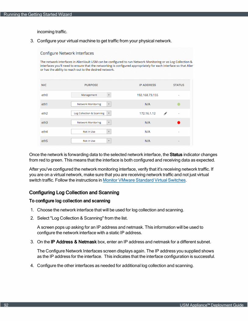
incoming traffic.
3. Configure your virtual machine to get traffic from your physical network.
Once the network is forwarding data to the selected network interface, the Status indicator changesfrom red to green. Thismeans that the interface is both configured and receiving data as expected.
After you've configured the networkmonitoring interface, verify that it's receiving network traffic. Ifyou are on a virtual network, make sure that you are receiving network traffic and not just virtualswitch traffic. Follow the instructions inMonitor VMware Standard Virtual Switches.
Configuring Log Collection and Scanning
To configure log collection and scanning
1. Choose the network interface that will be used for log collection and scanning.
2. Select "Log Collection & Scanning" from the list.
A screen pops up asking for an IP address and netmask. This information will be used toconfigure the network interface with a static IP address.
3. On the IP Address & Netmask box, enter an IP address and netmask for a different subnet.
The Configure Network Interfaces screen displays again. The IP address you supplied showsas the IP address for the interface. This indicates that the interface configuration is successful.
4. Configure the other interfaces as needed for additional log collection and scanning.
Running theGetting StartedWizard
92 USM Appliance™ Deployment Guide

Note: In some situations the network that you want to monitor may not be accessible fromthe IP address provided without setting up a route in the routing table. This is an extremecase and should not happen often. If a route is required, you will need to jailbreak thesystem using the AlienVault console and configure the route using the command line.
After you have finished configuring the network interfaces, click Next at the bottom-right cornerto proceed.
Discovering Assets in Your Network
Understanding what is in your environment is a critical step towards identifying threats andvulnerabilities.
When you complete the Asset Discovery task in the Getting StartedWizard, you can use the built-inasset discovery capability to do the following:
n Scan your networks and find assets
n Manually enter assets
n Import assets from aCSV file
Note: Before scanning a public network space, see "AddendumNotice Regarding ScanningLeased or Public Address Space" under SystemOverview in the USM Appliance DeploymentGuide.
Option 1: Scan Networks to Find Assets
This task informsAlienVault USM Appliance about the network topology. This enables you tosuccessfully run asset scans, vulnerability scans, and use other built-in capabilities.
Running theGetting StartedWizard
USM Appliance™ Deployment Guide 93
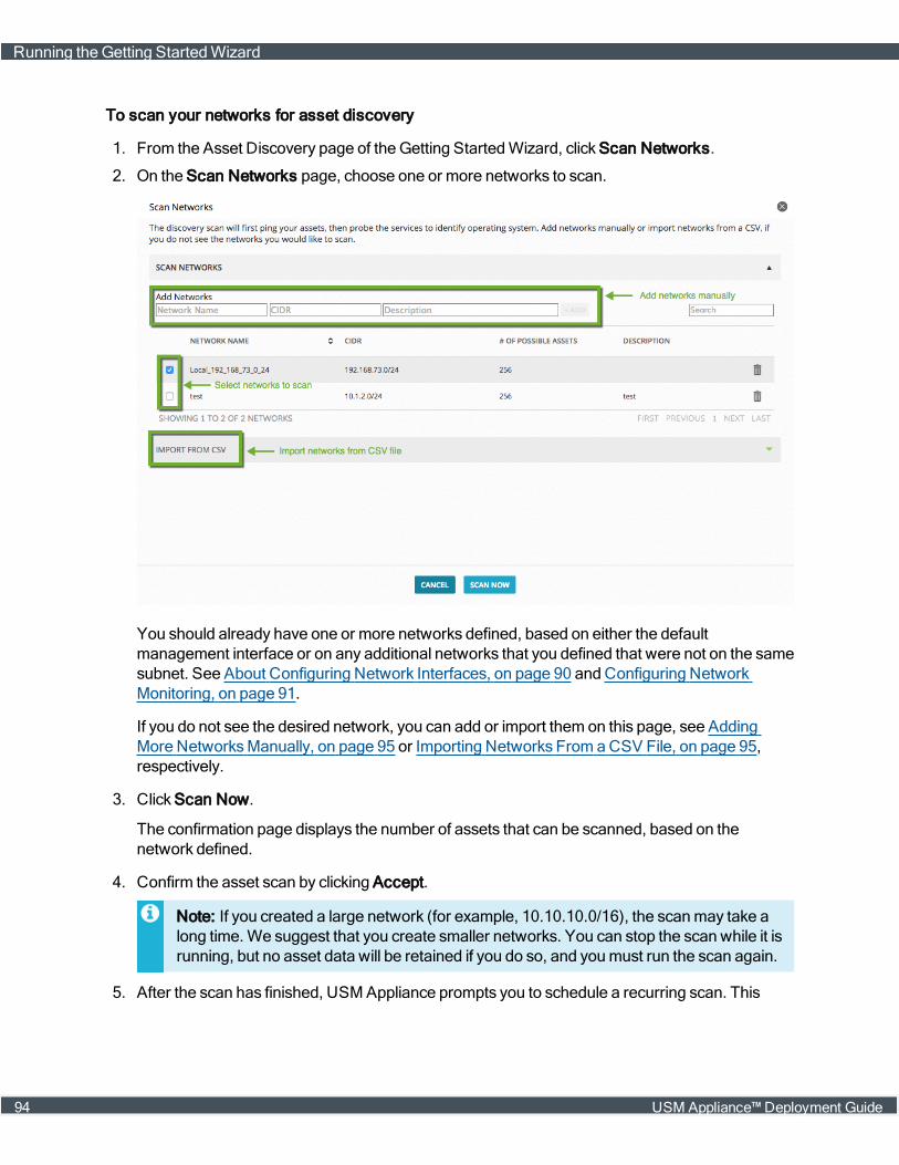
To scan your networks for asset discovery
1. From the Asset Discovery page of the Getting StartedWizard, click Scan Networks.
2. On the Scan Networks page, choose one or more networks to scan.
You should already have one or more networks defined, based on either the defaultmanagement interface or on any additional networks that you defined that were not on the samesubnet. See About Configuring Network Interfaces, on page 90 and Configuring NetworkMonitoring, on page 91.
If you do not see the desired network, you can add or import them on this page, see AddingMore NetworksManually, on page 95 or Importing Networks From aCSV File, on page 95,respectively.
3. Click Scan Now.
The confirmation page displays the number of assets that can be scanned, based on thenetwork defined.
4. Confirm the asset scan by clicking Accept.
Note: If you created a large network (for example, 10.10.10.0/16), the scanmay take along time. We suggest that you create smaller networks. You can stop the scan while it isrunning, but no asset data will be retained if you do so, and youmust run the scan again.
5. After the scan has finished, USM Appliance prompts you to schedule a recurring scan. This
Running theGetting StartedWizard
94 USM Appliance™ Deployment Guide
periodic scan helps you discover any changes in the environment promptly.
The default is a weekly scan.
6. To change the frequency to either daily or monthly, expand the list box. To select no scan, clickthe "x."
7. ClickOK to accept and continue.
Adding More Networks Manually
To add more networks manually
1. On the Scan Networks page, type ameaningful name into the Add Networks field to describethe network, for example, DMZ or EmployeeOffice.
2. Type the CIDR notation for the network.
3. (Optional) Type a description for the network to distinguish it, if helpful.
4. Click +Add.
Note: If youmake amistake and define the network incorrectly, use the delete icon (trashicon) to delete and re-enter the network.
Importing Networks From a CSV File
To import networks from a CSV file
Note: Pay attention to the formats allowed in the CSV files. The CIDR field is required. It canbe a comma-separated list. The delimiter for the columns is a semicolon.
1. Click Import from CSV to displaymore options.
2. Click Choose File and select a CSV file.
3. Click Import to upload the selected file.
Option 2: Import Assets from a CSV File
You can also import a list of assets from aCSV file.
To import assets from a CSV file
1. Click Import from CSV.
The Import Assets fromCSV popup appears.
2. Click Choose File and select a CSV file.
3. Click Import to upload the selected file.
A confirmation screen displays showing the number of hosts that have been imported.
Running theGetting StartedWizard
USM Appliance™ Deployment Guide 95

Option 3: Add Assets Manually
If you do not have access to a list of assets in the form of a CSV file, you can quickly add themmanually.
To add an asset manually
1. On the Scan & Add Assets page, type ameaningful name for the asset (for example, domaincontroller).
2. Type the IP address in the field provided.
3. Choose the asset type from the list.
4. Click +Add.
5. After you have finished adding all the assets, click Next at the bottom-right corner to proceed.
Deploying HIDS to Servers
We recommend deploying a host-based intrusion detection system (HIDS) to enable:
n File integritymonitoring
n Rootkit detection
n Event log collection
HIDS Agent Installation
TheGetting StartedWizard provides the following options for HIDS agent deployment:
Windows — HIDS agent is installed locally on specified hosts. AllWindows hostsmust meet theprerequisites described in the Asset Management topic, Deploying HIDS Agents, of theUSM Appliance User Guide.
UNIX/Linux — HIDS agents are not installed on hosts but provide agentless operation. UNIX andLinux systems aremonitored remotely for file integrity only. For information on installing HIDSagents on UNIX/Linux hosts, see Deploy the AlienVault HIDS Agents to LinuxHosts, on page 107 inthe IDS Configuration topic of the USM Appliance Deployment Guide.
To deploy HIDS
1. Select theWindows or the UNIX/Linux tab, as appropriate.
2. Type your Username and Password.
Note: For UNIX/Linux systems, this should be your SSH credentials.
3. (Windows only) Optionally, enter the Domain information.
4. From the asset tree on the right, choose the asset(s) on which you would like to deploy a HIDSagent.
Running theGetting StartedWizard
96 USM Appliance™ Deployment Guide
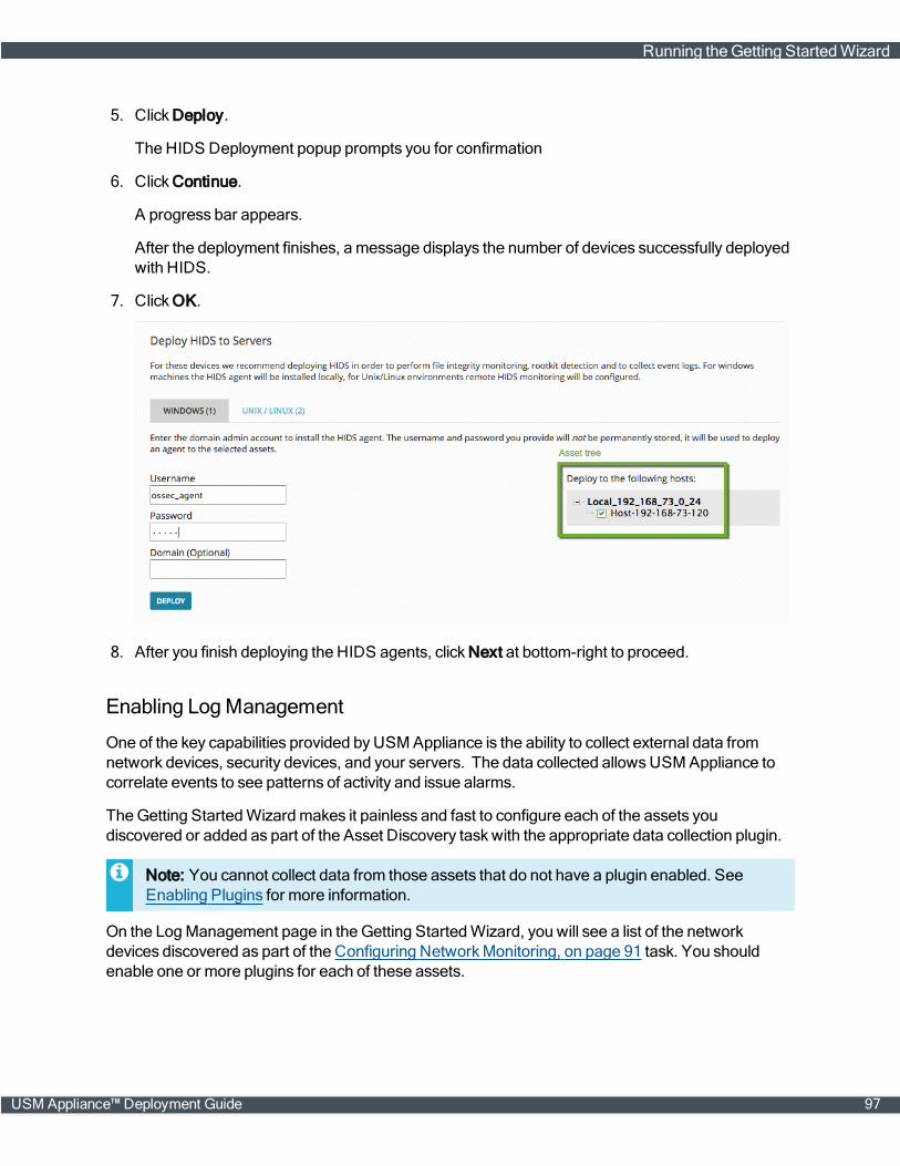
5. Click Deploy.
The HIDS Deployment popup prompts you for confirmation
6. Click Continue.
A progress bar appears.
After the deployment finishes, amessage displays the number of devices successfully deployedwith HIDS.
7. ClickOK.
8. After you finish deploying the HIDS agents, click Next at bottom-right to proceed.
Enabling LogManagement
One of the key capabilities provided byUSM Appliance is the ability to collect external data fromnetwork devices, security devices, and your servers. The data collected allowsUSM Appliance tocorrelate events to see patterns of activity and issue alarms.
TheGetting StartedWizardmakes it painless and fast to configure each of the assets youdiscovered or added as part of the Asset Discovery taskwith the appropriate data collection plugin.
Note: You cannot collect data from those assets that do not have a plugin enabled. SeeEnabling Plugins for more information.
On the LogManagement page in the Getting StartedWizard, you will see a list of the networkdevices discovered as part of the Configuring NetworkMonitoring, on page 91 task. You shouldenable one or more plugins for each of these assets.
Running theGetting StartedWizard
USM Appliance™ Deployment Guide 97
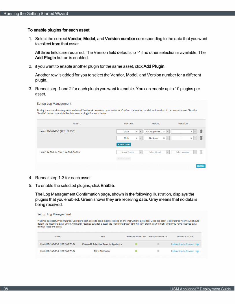
To enable plugins for each asset
1. Select the correct Vendor, Model, and Version number corresponding to the data that you wantto collect from that asset.
All three fields are required. The Version field defaults to ‘-‘ if no other selection is available. TheAdd Plugin button is enabled.
2. if you want to enable another plugin for the same asset, click Add Plugin.
Another row is added for you to select the Vendor, Model, and Version number for a differentplugin.
3. Repeat step 1 and 2 for each plugin you want to enable. You can enable up to 10 plugins perasset.
4. Repeat step 1-3 for each asset.
5. To enable the selected plugins, click Enable.
The LogManagement Confirmation page, shown in the following illustration, displays theplugins that you enabled. Green shows they are receiving data. Graymeans that no data isbeing received.
Running theGetting StartedWizard
98 USM Appliance™ Deployment Guide

6. To learn how to configure your assets to send data to USM Appliance, click Instructions toforward logs.
After you have enabled plugins for your assets, click Next at the bottom-right corner to proceed.
Connecting to AlienVault Open Threat Exchange®
AlienVault Open Threat Exchange® (OTX™) is an open information sharing and analysis network,created to put effective securitymeasureswithin the reach of all organizations. Unlike invitation-onlythreat sharing networks, OTX provides real-time, actionable information to all who want toparticipate.
Enabling AlienVault OTX in your installation will allow you to automatically share anonymous threatinformation with the OTX community. In return you will receive crowd-sourced threat updates every30minutes. The image below shows a sample of the data being sent from an AlienVaultUSM Appliance installation to OTX.
The following data are collected:
l source and/or destination IP address of an event
l name of the event
l number of times such event occurred
After you finish installing and configuring AlienVault USM Appliance (with OTX enabled), you will beable to quickly see which alarms indicatemalicious activity from a known bad actor on the Alarmspage. For more information, see UsingOTX in USM Appliance.
To enable OTX in your USMAppliance installation, youmust enter the OTX key and connect to yourOTX account. If you do not have anOTX account and would like to sign up for it, you can do so fromtheGetting StartedWizard.
To join OTX from the Getting Started Wizard
1. On the Join OTX screen, click Sign Up Now.
A popup takes you to the sign-up page on https://otx.alienvault.com/accounts/signup/.
2. Fill out the information (username, emaill address, and password) and click Sign Up.
Running theGetting StartedWizard
USM Appliance™ Deployment Guide 99
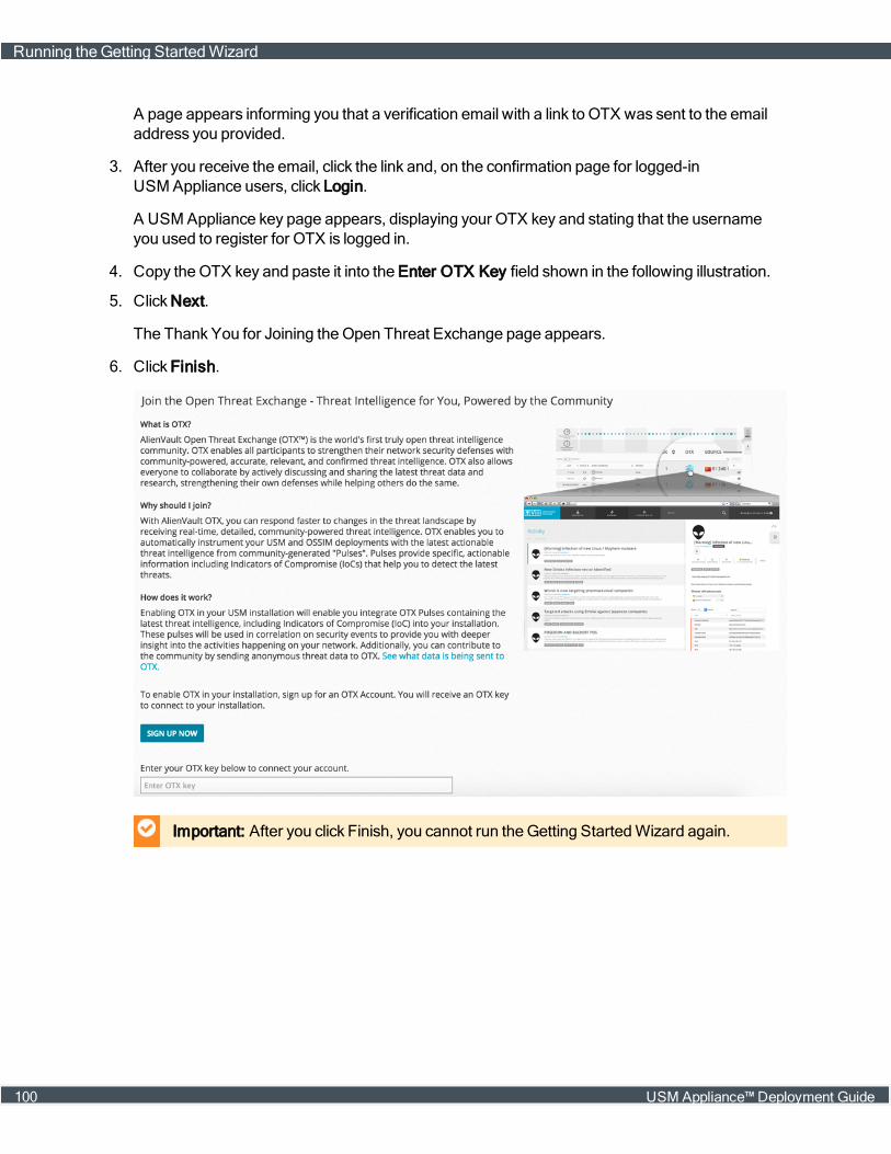
A page appears informing you that a verification email with a link to OTX was sent to the emailaddress you provided.
3. After you receive the email, click the link and, on the confirmation page for logged-inUSM Appliance users, click Login.
A USM Appliance key page appears, displaying your OTX key and stating that the usernameyou used to register for OTX is logged in.
4. Copy theOTX key and paste it into the Enter OTX Key field shown in the following illustration.
5. Click Next.
The Thank You for Joining theOpen Threat Exchange page appears.
6. Click Finish.
Important: After you click Finish, you cannot run theGetting StartedWizard again.
Running theGetting StartedWizard
100 USM Appliance™ Deployment Guide
IDS Configuration
Topics covered in this section include the following:
About Intrusion Detection Systems 102
AlienVault HIDS 103
AlienVault NIDS 136
USM Appliance™ Deployment Guide 101

About Intrusion Detection Systems
An Intrusion detection system (IDS) monitors networks and hosts in searching for malicious activitiesor policy violations, such as compromise of confidentiality, of system security, or of integrity. SomeIDS systemsmay be capable of stopping an intrusion attempt but this is neither required norexpected of an IDS system. IDS systems primarily focus on identifying possible intrusions, logginginformation about them, and reporting attempts, which security analysts can further analyze.
Classic network firewalls analyze network and transport layer headers, such as source anddestination IP address, protocol, and source and destination ports. However, attackers today do notonly aim at network and transport layers anymore, since network firewalls protect themwell;instead, they focus on exploiting vulnerabilities in operating systems, applications, and protocols.Network firewalls cannot detect such attacks. Therefore, you need additional security systems, suchas IDS, in order to detect them. Other examples of attacks that IDS can detect but firewall cannotinclude:
n Attacks that use tunneling, also known as "port forwarding", inside legitimate traffic or encryption
n Attackswithin internal networks
IDS systems generally fall into two categories:
n Network IDS (NIDS)—Placed at strategic points in a network tomonitors traffic between devicesand hosts within the network.
n Host-Based IDS (HIDS)— Runs on individual host systems andmonitors traffic from and to thehost system aswell as activities on the system itself.
USM Appliance provides both network and host-based intrusion detection capabilities.
About Network Intrusion Detection System (NIDS)
You typically place a Network Intrusion Detection System (NIDS) on the inside of a network firewall,where it canmonitor traffic from and to all devices. This way, the NIDS detectsmalicious activitiesthat fall through the network firewall. A NIDS usually works in promiscuousmode, bymonitoring acopy of the network traffic. It analyzes the traffic by comparing it against a database of knownattacks, also known as signatures, or by detecting anomalies in traffic patterns. When identified, aNIDS event is generated and reported to themanagement station.
You can use the following devices to forward network traffic to a NIDS:
l Network hubs
l Network switcheswith mirrored or spanned ports
Advantages of NIDS:
l It monitors the entire network's traffic if placed correctly in a network.
l It has no impact on network performance and throughput since it only analyzes the copy of thenetwork traffic.
About Intrusion Detection Systems
102 USM Appliance™ Deployment Guide
l It has no impact on network availability since it does not stand inline with network traffic.
Limitations of NIDS:
l It cannot analyze encrypted information.
l It requires continued signature updates.
l It requires specific network configuration to receive a copy of the traffic.
l It cannot block the attacks.
About Host Intrusion Detection System (HIDS)
A Host-base Intrusion Detection System (HIDS) monitors the behavior and state of a computersystem, aswell as network packets that the system sends and receives. A HIDS runs as an agent ona system, which sends detected events to amanagement station. The HIDS agent usuallymonitorswhich programs accesswhich resources and determines if an applicationmade an unauthorizedchange inmemory, a file, or a database. A HIDS can also look at the state of a system andmonitorsystem-specific logs in order to detect any significant changes on the system.
While a NIDS detects attacks sent over a network that the NIDS monitors, a HIDS detects thoseagainst the hosts on the network. NIDS cannot detect events in packet flows that use encryption, butHIDS can after the host decrypts the traffic. Ideally, a HIDS should work side-by-side with a NIDS.You can correlate events detected by both systems to determine if an attackwas successful. Forexample, a detected network attack followed by the creation of an administrator account on a servercouldmean that the attackwas successful.
Advantages of HIDS:
l It can detect if an attackwas successful or not.
l It monitors system activities.
l It can detect changes in files, memory, and applications.
l It can detect attacks that NIDS fails to detect, such as changes from a system console.
Limitations of HIDS:
l You need to deploy an agent to each host you want to monitor.
l It does not detect network scans or reconnaissance attacks.
l The host it resides on is susceptible to attack and disablement.
AlienVault HIDS
This section covers the following subtopics:
l About AlienVault HIDS
l Deploy AlienVault HIDS Agents
l File IntegrityMonitoring
AlienVault HIDS
USM Appliance™ Deployment Guide 103

l AgentlessMonitoring
l Working with AlienVault HIDS Rules
l Tutorial: Reading a Log File with an HIDS Agent onWindows
About AlienVault HIDS
The AlienVault HIDS included in the USM Appliance provides the following features:
n Logmonitoring and collection
n Rootkit detection
n File integritymonitoring
n Windows registry integritymonitoring
n Active response that can run applications on a server in response to certain triggers, such as spe-cific alerts or alert levels
AlienVault HIDS uses a server/agent architecture, where the HIDS agent resides on hosts you wantto monitor; and the HIDS server resides on the USM Appliance Sensor. The USM Appliance Sensorreceives events from the HIDS agents, normalizes them, and sends them to the USM ApplianceServer for analysis, correlation, and storage. AlienVault HIDS also has some limited support foragentless operation on Linux for log retrieval only.
You need to deploy the HIDS agents to client systems. The HIDS agent runs as a continuous in-memory service, interacting with the USM Appliance Sensor through UDP port 1514. TheUSM Appliance Sensor generates and distributes a pre-shared key to the HIDS agents, which thenuse the key to authenticate the communication between the HIDS agents and the USM ApplianceSensor.
AlienVault HIDS
104 USM Appliance™ Deployment Guide
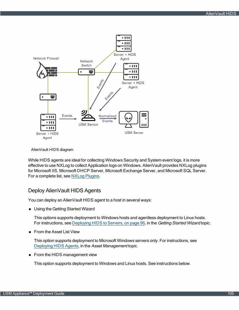
AlienVault HIDS diagram
While HIDS agents are ideal for collectingWindowsSecurity and System event logs, it ismoreeffective to use NXLog to collect Application logs onWindows. AlienVault providesNXLog pluginsfor Microsoft IIS, Microsoft DHCP Server, Microsoft Exchange Server, andMicrosoft SQL Server.For a complete list, see NXLog Plugins.
Deploy AlienVault HIDSAgents
You can deploy an AlienVault HIDS agent to a host in several ways:
n Using theGetting StartedWizard
This options supports deployment toWindows hosts and agentless deployment to Linux hosts.For instructions, see Deploying HIDS to Servers, on page 96, in the Getting StartedWizard topic.
n From the Asset List View
This option supports deployment to Microsoft Windows servers only. For instructions, seeDeploying HIDS Agents, in the Asset Management topic.
n From the HIDS management view
This option supports deployment toWindows and Linux hosts. See instructions below.
AlienVault HIDS
USM Appliance™ Deployment Guide 105
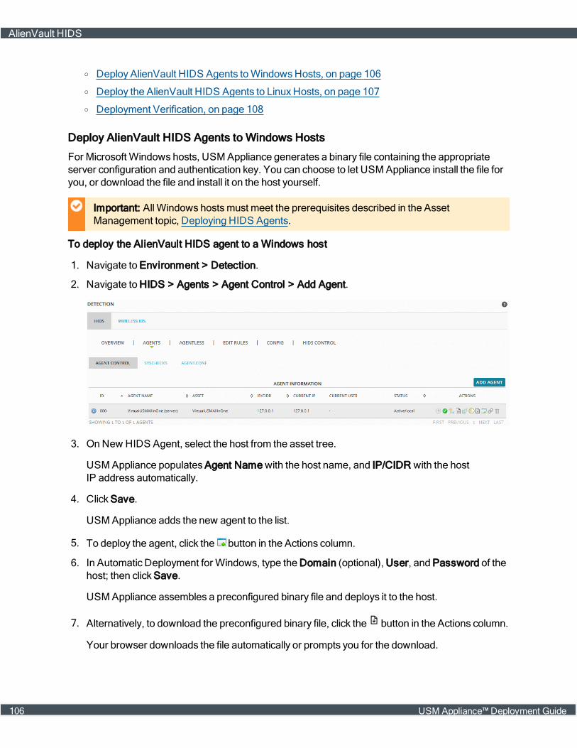
o Deploy AlienVault HIDS Agents toWindowsHosts, on page 106
o Deploy the AlienVault HIDS Agents to LinuxHosts, on page 107
o Deployment Verification, on page 108
Deploy AlienVault HIDS Agents to Windows Hosts
For Microsoft Windows hosts, USM Appliance generates a binary file containing the appropriateserver configuration and authentication key. You can choose to let USM Appliance install the file foryou, or download the file and install it on the host yourself.
Important: AllWindows hostsmust meet the prerequisites described in the AssetManagement topic, Deploying HIDS Agents.
To deploy the AlienVault HIDS agent to a Windows host
1. Navigate to Environment > Detection.
2. Navigate to HIDS > Agents > Agent Control > Add Agent.
3. On New HIDS Agent, select the host from the asset tree.
USM Appliance populates Agent Namewith the host name, and IP/CIDR with the hostIP address automatically.
4. Click Save.
USM Appliance adds the new agent to the list.
5. To deploy the agent, click the button in the Actions column.
6. In Automatic Deployment for Windows, type the Domain (optional), User, and Password of thehost; then click Save.
USM Appliance assembles a preconfigured binary file and deploys it to the host.
7. Alternatively, to download the preconfigured binary file, click the button in the Actions column.
Your browser downloads the file automatically or prompts you for the download.
AlienVault HIDS
106 USM Appliance™ Deployment Guide

8. Transfer the file, named ossec_installer_<agent_id>.exe, to theMicrosoft Windows host.
9. On theWindows host, double-click to run the executable.
The installer runs in a console briefly, then displays a progress bar until completion.
Deploy the AlienVault HIDS Agents to Linux Hosts
Important: For Linux hosts, depending on which distribution of Linux you use, AlienVaultrecommends that you download the corresponding ossec-hids-agent installer file from theOSSEC's Downloads page directly, and then follow their instructions to complete theinstallation.
After you have successfully installed the HIDS agent on the LInux host, perform the steps below toconnect it to the USM Appliance.
To add the HIDS agent to USM Appliance
1. Navigate to Environment > Detection.
2. Navigate to HIDS > Agents > Agent Control > Add Agent.
3. On New HIDS Agent, select the host from the asset tree.
USM Appliance populates Agent Namewith the host name, and IP/CIDR with the hostIP address automatically.
4. Click Save.
USM Appliance adds the new agent to the list.
5. To extract the key for the agent, click the button in the Actions column, and then copy the keythat displays.
6. Login to the Linux host, run /var/ossec/bin/manage_agents, and then enter I to import thekey you copied in the previous step.
Note: On some installations, Centos, for example, the commandmay be manage_clientinstead of manage_agents.
7. Edit /var/ossec/etc/ossec-agent.conf to change the server IP address to theUSM Appliance.
AlienVault HIDS
USM Appliance™ Deployment Guide 107

8. Start the HIDS agent if it is not already running:
service ossec startchkconfig ossec-hids on
9. On the USM Appliance, navigate to Environment > Detection, click HIDS Control, and thenRestart.
Deployment Verification
You can verify the deployment both on the HIDS agent and the USM Appliance.
On the HIDS agents, you can check the ossec.log file to make sure that amessage similar to thefollowing exists:
2015/09/18 09:07:38 ossec-agent: INFO: Started (pid: 3440).2015/09/18 09:07:38 ossec-agent(4102): INFO: Connected to the server(10.47.30.100:1514).
To check the agent log file on the Windows hosts
1. Go to Start > OSSEC > Manage Agent.
2. In OSSEC Agent Manager, click View and select View Logs.
This opens the ossec.log file on the agent.
To check the agent log file on the Linux hosts
1. Login to the Linux host.
2. In a console, enter the following:
more /var/ossec/logs/ossec.log
On the USM Appliance, make sure there exist AlienVault HIDS events.
To verify the HIDS deployment on the USM Appliance
1. Navigate to Environment > Detection.
TheOverview page for HIDS displays.
2. Ensure that the Status column for the deployed agents display Active, and the Trend chart is notempty.
AlienVault HIDS
108 USM Appliance™ Deployment Guide
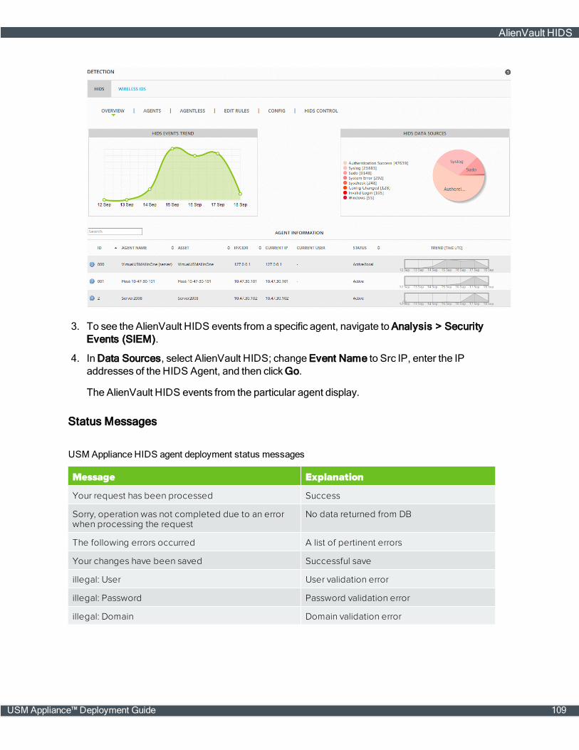
3. To see the AlienVault HIDS events from a specific agent, navigate to Analysis > SecurityEvents (SIEM).
4. In Data Sources, select AlienVault HIDS; change Event Name to Src IP, enter the IPaddresses of the HIDS Agent, and then clickGo.
The AlienVault HIDS events from the particular agent display.
Status Messages
Message Explanation
Your request has been processed Success
Sorry, operation was not completed due to an errorwhen processing the request
No data returned from DB
The following errors occurred A list of pertinent errors
Your changes have been saved Successful save
illegal: User User validation error
illegal: Password Password validation error
illegal: Domain Domain validation error
USM Appliance HIDS agent deployment status messages
AlienVault HIDS
USM Appliance™ Deployment Guide 109
File Integrity Monitoring
You can configure AlienVault HIDS to perform File IntegrityMonitoring (FIM), which identifieschanges in system files, folders, andMicrosoft Windows registries. The process that identifies thesechanges is syscheck. The syscheck process scans the host at user-defined intervals and storeschecksums of watched files. The system then generates an event when a checksum changes.
In addition to using syscheck, you can also configureWindows systems so that AlienVault HIDSagents forward object access audit events for USM Appliance to process. These events providemore information on operations affecting file and folder objects, such aswho performed specificactions or operations on an object. For more information, see ConfiguringWindowsSystems toView WindowsAudit Object Access Events.
Configuring File Integrity Monitoring
Every HIDS agent includes an ossec.conf file with some default settings for syscheck. OnMicrosoft Windows hosts, you can find this file in C:\Program Files (x86)\ossec-agent, and onLinux, in /var/ossec/etc.
When youmake changes through the USM Appliance web interface, USM Appliance records yourmodifications in the agent.conf file and stores it for distribution.When the agent authenticates, itwill download the shared configuration andmerge it with the local copy. The shared file will takeprecedence, overwriting any local configuration.
Default settings for the ossec.conf file stored on a host system are configured when the HIDSagent is first installed or deployed on a host system. In addition, an ossec.conf file containingsyscheck and other global options is defined and stored on theUSM Appliance Server. For moreinformation on viewing and configuring this file, see To configureUSM Appliance server-side (global)ossec.conf settings.
To change syscheck options for all agents
1. Navigate to Environment > Detection.
2. On HIDS, click Agents, and then click Syschecks.
3. Configure the options according to your needs.
4. Click Save after making changes in each section.
5. (Optional) Click Agent.conf to confirm the changes in XML format.
6. To apply your changes immediately, click HIDS Control, and then Restart .
To configureUSM Appliance server-side (global) ossec.conf settings
1. Navigate to Environment > Detection.
2. On HIDS, click Config, and then click Syschecks.
AlienVault HIDS
110 USM Appliance™ Deployment Guide
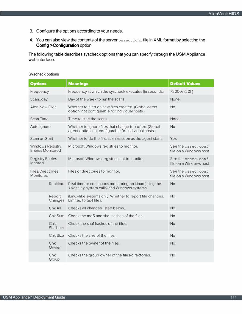
3. Configure the options according to your needs.
4. You can also view the contents of the server ossec.conf file in XML format by selecting theConfig >Configuration option.
The following table describes syscheck options that you can specify through the USM Applianceweb interface.
Options Meanings Default Values
Frequency Frequency at which the syscheck executes (in seconds). 72000s (20h)
Scan_day Day of the week to run the scans. None
Alert New Files Whether to alert on new files created. (Global agentoption; not configurable for individual hosts.)
No
Scan Time Time to start the scans. None
Auto Ignore Whether to ignore files that change too often. (Globalagent option; not configurable for individual hosts.)
No
Scan on Start Whether to do the first scan as soon as the agent starts. Yes
Windows RegistryEntries Monitored
Microsoft Windows registries to monitor. See the ossec.conffile on a Windows host
Registry EntriesIgnored
Microsoft Windows registries not to monitor. See the ossec.conffile on a Windows host
Files/DirectoriesMonitored
Files or directories to monitor. See the ossec.conffile on a Windows host
Realtime Real time or continuous monitoring on Linux (using theinotify system calls) and Windows systems.
No
ReportChanges
(Linux-like systems only) Whether to report file changes.Limited to text files.
No
Chk All Checks all changes listed below. No
Chk Sum Check the md5 and sha1 hashes of the files. No
ChkSha1sum
Check the sha1 hashes of the files. No
Chk Size Checks the size of the files. No
ChkOwner
Checks the owner of the files. No
ChkGroup
Checks the group owner of the files/directories. No
Syscheck options
AlienVault HIDS
USM Appliance™ Deployment Guide 111

Options Meanings Default Values
ChkPerm
Checks the permission of the files/directories. No
File/DirectoriesIgnored
Files or directories not to monitor. See the ossec.conffile on a Windows host
Syscheck options (Continued)
About Auto Ignore and Realtime
With Auto Ignore set to No, you receive alerts on every file change, regardless how many times it ischanged. If you also select the Realtime option, the alert stops after the third change, equivalent tosetting Auto Ignore to Yes.
About Alert New Files
You can configure AlienVault HIDS to alert on new files, but it does not report in real time, becauseAlienVault HIDS can only detect new files on a full scan.
To enable alerting on new files
1. Change Alert New Files to Yes.
2. Specify the directory in which to detect the new files.
3. Select Chk All.
About Report Changes
The report_changes setting does not warn users against enabling this setting globally or reportingchanges on the Linux root file system. Setting this option globally, or reporting on changes to the rootfile system, will likely create a large number of events, which could potentially fill up all available diskspace and impact USM Appliance operation.
Specifying Different Syscheck Options for Different Hosts
You can configure different syscheck options for different hosts, by entering them in the agent.conffile manually. Ensure that you
l Use a separate <agent_config> element for each host you need to configure.
l Use the name attribute to denote the name of the host. (This is the agent name used when addingthe agent to the detection section.)
l Specify the options you want to change inside the <syscheck> element.
l Repeat all every host you want to configure.
The following example shows different syscheck options for host AD2012 andWin2008:
<agent_config name="AD2012"><syscheck><frequency>21600</frequency>
AlienVault HIDS
112 USM Appliance™ Deployment Guide

<scan_on_start>yes</scan_on_start><directories check_all="yes">C:\temp</directories></syscheck></agent_config>
<agent_config name="Win2008"><syscheck><frequency>3600</frequency><scan_on_start>yes</scan_on_start><directories check_all="yes">C:\topsecret</directories></syscheck></agent_config>
Instead of making these changes on the hosts one-by-one, you can configure them in theUSM Appliance web interface.
To configure different syscheck options for different hosts
1. Navigate to Environment > Detection.
2. On HIDS, click Agents > Agent.conf.
By default, this page is blank.
3. Type or paste in the changes you want to make.
4. Click Save.
5. (Optional) Click Syscheck. Notice that a list appears towards the upper-right corner with thename of the first entry in agent.conf.
AlienVault HIDS
USM Appliance™ Deployment Guide 113

6. To apply your changes immediately, click HIDS Control, and then Restart.
Viewing the File Integrity Monitoring Events
Each time an AlienVault HIDS agent detects a change in amonitored file or directory,USM Appliance creates an event and stores it in the database.
To view FIM events
1. Navigate to Analysis > Security Events (SIEM).
2. In Data Sources, select "AlienVault HIDS".
3. In Event Name, type "Integrity".
4. ClickGo.
AlienVault HIDS
114 USM Appliance™ Deployment Guide

5. View event details to determine which file has changed.
Configuring Windows Systems to View Windows Audit Object Access Events
To configureWindows systems so that AlienVault USM Appliance can view Windows audit objectaccess events, you need to first edit local security policy settings. After applying policy changes toinclude audit object events inWindows security logs, the AlienVault HIDS agent will forward thoseevents to USM Appliance.
Note: You can only set up file and folder auditing on NTFS drives.
AlienVault HIDS
USM Appliance™ Deployment Guide 115

To define policy settings for object access audit events
1. On a selectedWindows system, open the Local Group Policy Editor.
2. Go to Computer Configuration > Windows Settings > Security Settings > Local Policies >Audit Policy.
3. Edit the Audit object access policy and enable auditing of Success and Failure attempts.
The following display shows an example:
To apply or modify auditing policy settings
1. OpenWindows Explorer and navigate to the file or folder you want to audit.
2. Right-click on the file or folder and select Properties.
3. Select the Security tab and click Advanced.
4. Select the Auditing tab and click Continue if prompted.
5. Perform one of the following operations:
AlienVault HIDS
116 USM Appliance™ Deployment Guide
o To set up auditing for a new user or group, click Add. In the Enter the object name to selectfield, type the name of the user or group that you want to audit, then clickOK.
o To remove auditing for an existing group or user, highlight the group or user name, clickRemove, and then clickOK. You can skip remaining steps.
o To view or change auditing for an existing group or user, click its name and then click Edit.
6. In the Apply onto box, click the location that you want to audit.
7. In the Access box, indicate what actions you want to audit by selecting the appropriate checkboxes.
8. If you want to prevent subordinate files and subfolders of the original object from inheriting auditsettings, select the Apply these auditing entries to objects and/or containers within this con-tainer only check box.
Note: Because theWindows security log is limited in size, select the files and folders to beaudited carefully, since new audit events will be stored there. Also, consider the amount ofdisk space that you want to devote to the security log. Themaximum size for the securitylog is set in Event Viewer.
After enabling object access auditing, you can view the security log in Event Viewer to see thatthe audit events are now collected. The AlienVault HIDS agent will forward those events toUSM Appliance.
USBDeviceMonitoring onWindows Systems
In AlienVault USM Appliance version 5.3, Host Intrusion Detection System (HIDS) rules and pluginshave been updated to capture USB device events onWindowsmachines.
Configuration Changes on the HIDS Agent
If you are deploying USM Appliance version 5.3 or later, you do not need to do anything. This featureis enabled by default.
If you are updating to USM Appliance version 5.3 or later from a previous version, and you want touse the USB device detection feature, you need to do one of the following:
l On the host you wish tomonitor, remove the existing HIDS agent and redeploy it. For instruc-tions, see Deploy AlienVault HIDS Agents toWindowsHosts, on page 106.
l Alternatively, you can change the configuration onWindowsmanually, as detailed below.
Change the Configuration on Windows Manually
Since full_commandmust be configured in eachWindows system's ossec.conf file, you need tochange the HIDS agent configuration on eachWindowsmachine that you want to monitor USBdevices.
AlienVault HIDS
USM Appliance™ Deployment Guide 117
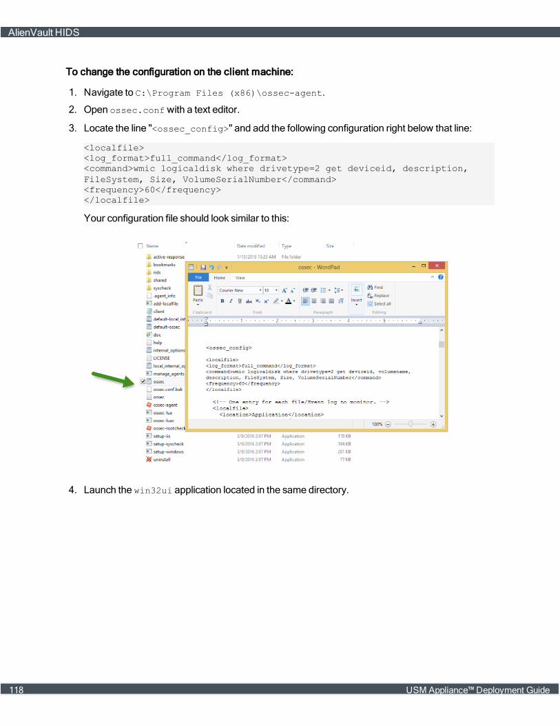
To change the configuration on the client machine:
1. Navigate to C:\Program Files (x86)\ossec-agent.
2. Open ossec.confwith a text editor.
3. Locate the line "<ossec_config>" and add the following configuration right below that line:
<localfile><log_format>full_command</log_format><command>wmic logicaldisk where drivetype=2 get deviceid, description,FileSystem, Size, VolumeSerialNumber</command><frequency>60</frequency></localfile>
Your configuration file should look similar to this:
4. Launch the win32ui application located in the same directory.
AlienVault HIDS
118 USM Appliance™ Deployment Guide

a. Select Manage.
b. Click Restart.
Verification
OnceUSB activity has been detected on that host, you should be able to see new AlienVault HIDSevents with the event name AlienVault HIDS: New USB Device Found. And the Event Detailspane includes information about Drive, FileSystem, Size, and Serial Number:
AlienVault HIDS
USM Appliance™ Deployment Guide 119

AgentlessMonitoring
AlienVault HIDS allows you to run integrity checking without agents installed on hosts, networkdevices, routers, firewalls, or switches. Agentlessmonitoring detects checksum changes in files orruns diffs to showswhat exactly has changed.
Prerequisites
Before enabling agentlessmonitoring, make sure you have done the following:
n Open the SSH daemon on your device listening on TCP port 22.
n Set up firewall rules to allow SSH traffic between USM Appliance and your device.
AlienVault HIDS runs checks periodically, communicating with monitored devices through TCP port22 using the SSH protocol.
AlienVault HIDS
120 USM Appliance™ Deployment Guide
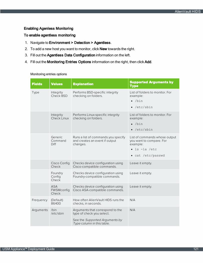
Enabling Agenless Monitoring
To enable agentless monitoring
1. Navigate to Environment > Detection > Agentless.
2. To add a new host you want to monitor, click New towards the right.
3. Fill out the Agentless Data Configuration information on the left.
4. Fill out theMonitoring Entries Options information on the right, then click Add.
Fields Values Explanation Supported Arguments byType
Type IntegrityCheck BSD
Performs BSD-specific integritychecking on folders.
List of folders to monitor. Forexample:l /bin
l /etc/sbin
IntegrityCheck Linux
Performs Linux-specific integritychecking on folders.
List of folders to monitor. Forexample:
l /bin
l /etc/sbin
GenericCommandDiff
Runs a list of commands you specifyand creates an event if outputchanges.
List of commands whose outputyou want to compare. Forexample:l ls -la /etc
l cat /etc/passwd
Cisco ConfigCheck
Checks device configuration usingCisco-compatible commands.
Leave it empty.
FoundryConfigCheck
Checks device configuration usingFoundry-compatible commands.
Leave it empty.
ASAFWSMconfigCheck
Checks device configuration usingCisco ASA-compatible commands.
Leave it empty.
Frequency (Default)86400
How often AlienVault HIDS runs thechecks, in seconds.
N/A
Arguments /bin/etc/sbin
Arguments that correspond to thetype of check you select.
See the Supported Arguments byType column in this table.
N/A
Monitoring entries options
AlienVault HIDS
USM Appliance™ Deployment Guide 121

Important: USM Appliance can only process one argument for every entry. If you need torunmultiple commands, put them in separate entries. The added entries appear inMonitoring Entries Added.
5. Click Update.
6. To apply your changes immediately, click HIDS Control, and then Restart.
This starts the agentless service in the AlienVault HIDS.
Verifying the Agentless Deployment on USM Appliance
You can verify that you have successfully deployed the agentlessmonitoring in the following ways:
n OnEnvironment > Detection > Agentless, the status of the host displays a green checkmarkand the Agentless Status: displaysRunning.
n OnEnvironment > Detection > HIDS Control, make sure that you see "Agentless is running" in
AlienVault HIDS
122 USM Appliance™ Deployment Guide

green.
n On Environment > Detection > HIDS Control > HIDS Log, make sure that you see the periodicchecks performed.
n OnAnalysis > Security Events (SIEM), make sure that you see events coming from themonitored host or device.
AlienVault HIDS
USM Appliance™ Deployment Guide 123
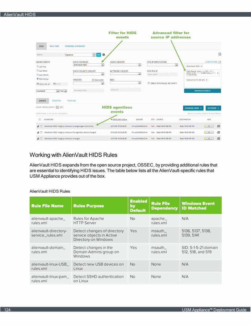
Working with AlienVault HIDSRules
AlienVault HIDS expands from the open source project, OSSEC, by providing additional rules thatare essential to identifying HIDS issues. The table below lists all the AlienVault-specific rules thatUSM Appliance provides out of the box.
Rule File Name Rules PurposeEnabledbyDefault
Rule FileDependency
Windows EventID Matched
alienvault-apache_rules.xml
Rules for ApacheHTTP Server
No apache_rules.xml
N/A
alienvault-directory-service_rules.xml
Detect changes of directoryservice objects in ActiveDirectory on Windows
Yes msauth_rules.xml
5136, 5137, 5138,5139, 5141
alienvault-domain_rules.xml
Detect changes in theDomain Admins group onWindows
Yes msauth_rules.xml
SID: S-1-5-21 domain512, 518, and 519
alienvault-linux-USB_rules.xml
Detect new USB devices onLinux
No None N/A
alienvault-linux-pam_rules.xml
Detect SSHD authenticationon Linux
No None N/A
AlienVault HIDS Rules
AlienVault HIDS
124 USM Appliance™ Deployment Guide
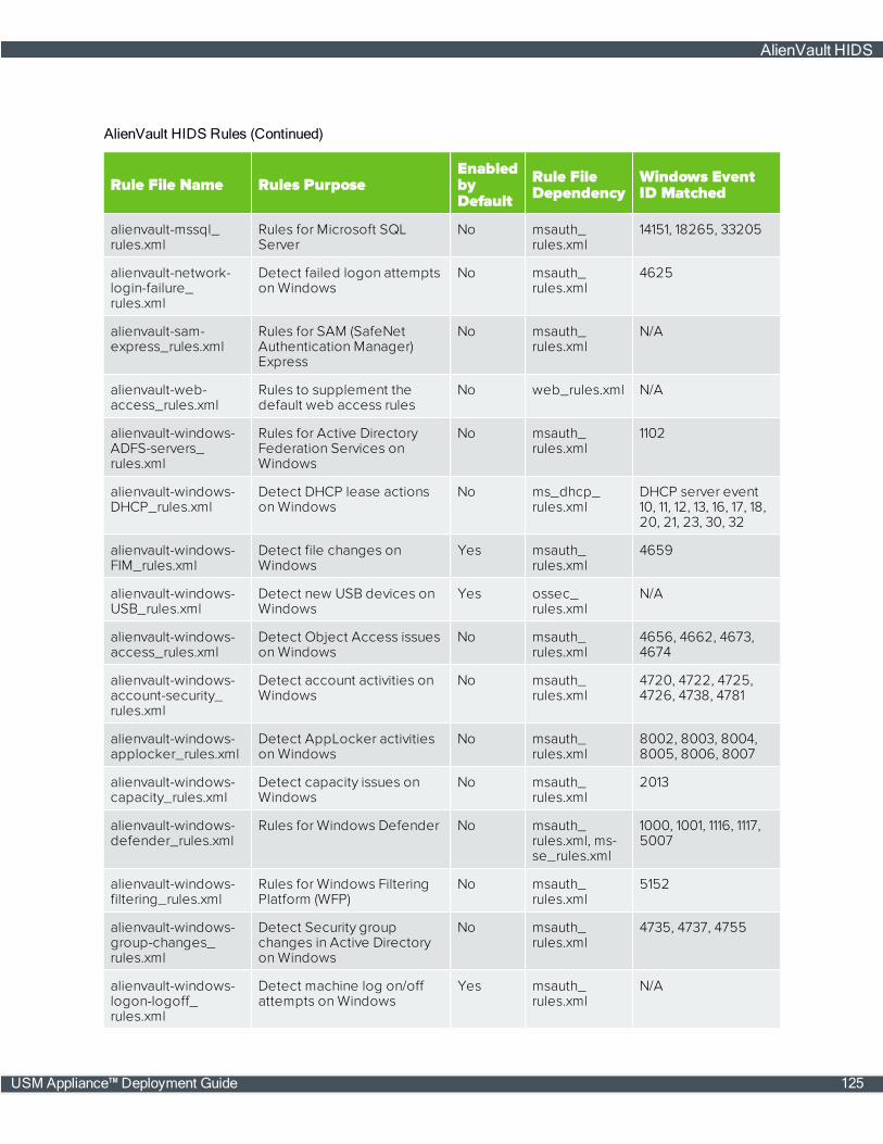
Rule File Name Rules PurposeEnabledbyDefault
Rule FileDependency
Windows EventID Matched
alienvault-mssql_rules.xml
Rules for Microsoft SQLServer
No msauth_rules.xml
14151, 18265, 33205
alienvault-network-login-failure_rules.xml
Detect failed logon attemptson Windows
No msauth_rules.xml
4625
alienvault-sam-express_rules.xml
Rules for SAM (SafeNetAuthentication Manager)Express
No msauth_rules.xml
N/A
alienvault-web-access_rules.xml
Rules to supplement thedefault web access rules
No web_rules.xml N/A
alienvault-windows-ADFS-servers_rules.xml
Rules for Active DirectoryFederation Services onWindows
No msauth_rules.xml
1102
alienvault-windows-DHCP_rules.xml
Detect DHCP lease actionson Windows
No ms_dhcp_rules.xml
DHCP server event10, 11, 12, 13, 16, 17, 18,20, 21, 23, 30, 32
alienvault-windows-FIM_rules.xml
Detect file changes onWindows
Yes msauth_rules.xml
4659
alienvault-windows-USB_rules.xml
Detect new USB devices onWindows
Yes ossec_rules.xml
N/A
alienvault-windows-access_rules.xml
Detect Object Access issueson Windows
No msauth_rules.xml
4656, 4662, 4673,4674
alienvault-windows-account-security_rules.xml
Detect account activities onWindows
No msauth_rules.xml
4720, 4722, 4725,4726, 4738, 4781
alienvault-windows-applocker_rules.xml
Detect AppLocker activitieson Windows
No msauth_rules.xml
8002, 8003, 8004,8005, 8006, 8007
alienvault-windows-capacity_rules.xml
Detect capacity issues onWindows
No msauth_rules.xml
2013
alienvault-windows-defender_rules.xml
Rules for Windows Defender No msauth_rules.xml, ms-se_rules.xml
1000, 1001, 1116, 1117,5007
alienvault-windows-filtering_rules.xml
Rules for Windows FilteringPlatform (WFP)
No msauth_rules.xml
5152
alienvault-windows-group-changes_rules.xml
Detect Security groupchanges in Active Directoryon Windows
No msauth_rules.xml
4735, 4737, 4755
alienvault-windows-logon-logoff_rules.xml
Detect machine log on/offattempts on Windows
Yes msauth_rules.xml
N/A
AlienVault HIDS Rules (Continued)
AlienVault HIDS
USM Appliance™ Deployment Guide 125

Rule File Name Rules PurposeEnabledbyDefault
Rule FileDependency
Windows EventID Matched
alienvault-windows-password-change-rules.xml
Detect password changeattempts on Windows
No msauth_rules.xml
4723, 4724
alienvault-windows-powershell_rules.xml
Rules for WindowsPowerShell commands
No msauth_rules.xml
800
alienvault-windows-process_rules.xml
Detect new processes onWindows
No msauth_rules.xml
4688, 4689
alienvault-windows-service-control-manager_rules.xml
Rules for Service ControlManager (Windows)
No msauth_rules.xml
7036, 7045
alienvault-windows-shutdown_rules.xml
Detect power off attemptson Windows
No msauth_rules.xml
1074
alienvault-windows-workstation-logon-logoff_rules.xml
Detect user logon/offattempts on Windows
Yes msauth_rules.xml
528, 540, 672, 673,4624, 4672, 4768,4769, 4771
local_rules.xml A file to hold user-definedHIDS rules. it contains asample rule initially.
Yes None bydefault
N/A
AlienVault HIDS Rules (Continued)
AlienVault delivers new HIDS rules or fixes to existing rules through the bi-weekly AlienVault LabsThreat Intelligence Updates, on page 244. For a complete list of rules enabled by default, go toEnvironment > Detection > HIDS > Config > Rules. USM Appliance displays the enabled rules onthe left and disabled rules on the right.
AlienVault HIDS
126 USM Appliance™ Deployment Guide

You can enablemore rules based on your business needs. See Enabling / Disabling AlienVaultHIDS Rules, on page 127.
Additionally, you can edit existing rules or create your own so that theywork better in yourenvironment. See Editing / Creating CustomRules for AlienVault HIDS, on page 129.
Enabling / Disabling AlienVault HIDS Rules
Before deciding whether to enable or disable an AlienVault HIDS rule, you will want to understandwhat the rule does first. USM Appliance allows you to view the entire rule file from the webUI.
Note: AlienVault HIDS rules are read-only. You cannot change them.
AlienVault HIDS
USM Appliance™ Deployment Guide 127
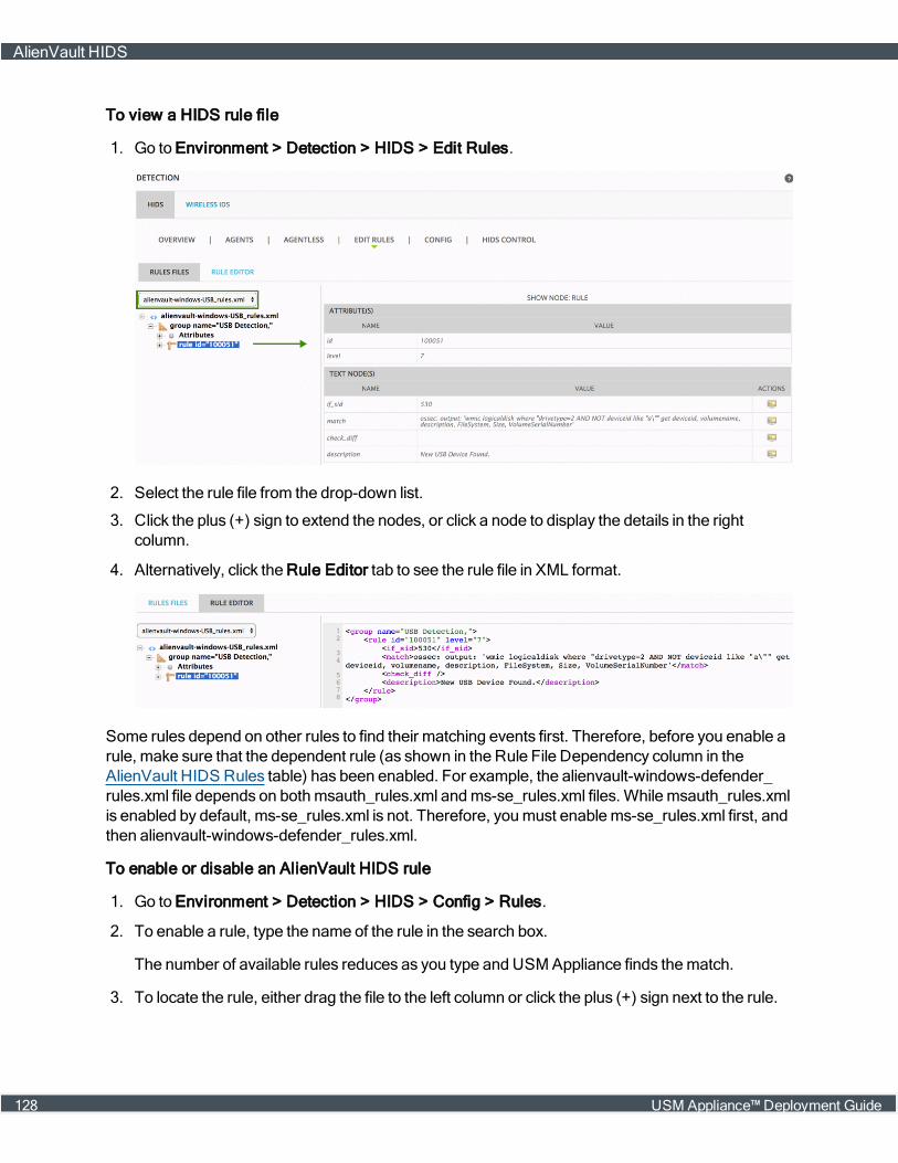
To view a HIDS rule file
1. Go to Environment > Detection > HIDS > Edit Rules.
2. Select the rule file from the drop-down list.
3. Click the plus (+) sign to extend the nodes, or click a node to display the details in the rightcolumn.
4. Alternatively, click the Rule Editor tab to see the rule file in XML format.
Some rules depend on other rules to find their matching events first. Therefore, before you enable arule, make sure that the dependent rule (as shown in the Rule File Dependency column in theAlienVault HIDS Rules table) has been enabled. For example, the alienvault-windows-defender_rules.xml file depends on bothmsauth_rules.xml andms-se_rules.xml files. While msauth_rules.xmlis enabled by default, ms-se_rules.xml is not. Therefore, youmust enablems-se_rules.xml first, andthen alienvault-windows-defender_rules.xml.
To enable or disable an AlienVault HIDS rule
1. Go to Environment > Detection > HIDS > Config > Rules.
2. To enable a rule, type the name of the rule in the search box.
The number of available rules reduces as you type and USM Appliance finds thematch.
3. To locate the rule, either drag the file to the left column or click the plus (+) sign next to the rule.
AlienVault HIDS
128 USM Appliance™ Deployment Guide

4. To disable a rule, locate the file in the left column. Either drag the file to the right column or clicktheminus (-) sign next to the rule.
5. Click Save.
6. Youmust restart the HIDS Service for the changes to take effect:
o On the same page, click the HIDS Control tab, and then click Restart on the resulting page.
Editing / Creating Custom Rules for AlienVault HIDS
You are not allowed to change any of the AlienVault HIDS rules, but you can create your own rulesto detect HIDS issues in your environment. AlienVault recommends that you put your rules in thelocal_rules.xml file, which is enabled by default and loaded at last so that it is not overwritten bythe other rule files. You can add or remove rules from local_rules.xml in the webUI.
To create or modify a custom HIDS rule
1. Go to Environment > Detection > HIDS > Edit Rules.
2. Select local_rules.xml from the drop-down list.
3. Click group name="local,syslog," to display the details in the right column.
A sample rule with id 150000 displays.
4. Click the clone rule icon ( ) to clone the sample rule.
Another rule with rule id 150000 displays.
5. Click Save.
Note: Save your new rule in order to make changes to it.
6. Click the edit rule icon ( ) next to the newly created rule.
The details of the rule display.
7. Change the id so that it is unique.
AlienVault HIDS
USM Appliance™ Deployment Guide 129
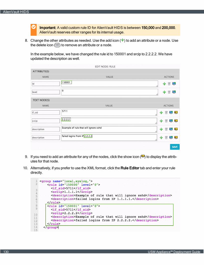
Important: A valid custom rule ID for AlienVault HIDS is between 150,000 and 200,000.AlienVault reserves other ranges for its internal usage.
8. Change the other attributes as needed. Use the add icon ( ) to add an attribute or a node. Usethe delete icon ( ) to remove an attribute or a node.
In the example below, we have changed the rule id to 150001 and srcip to 2.2.2.2. We haveupdated the description aswell.
9. If you need to add an attribute for any of the nodes, click the show icon ( ) to display the attrib-utes for that node.
10. Alternatively, if you prefer to use the XML format, click the Rule Editor tab and enter your ruledirectly.
AlienVault HIDS
130 USM Appliance™ Deployment Guide
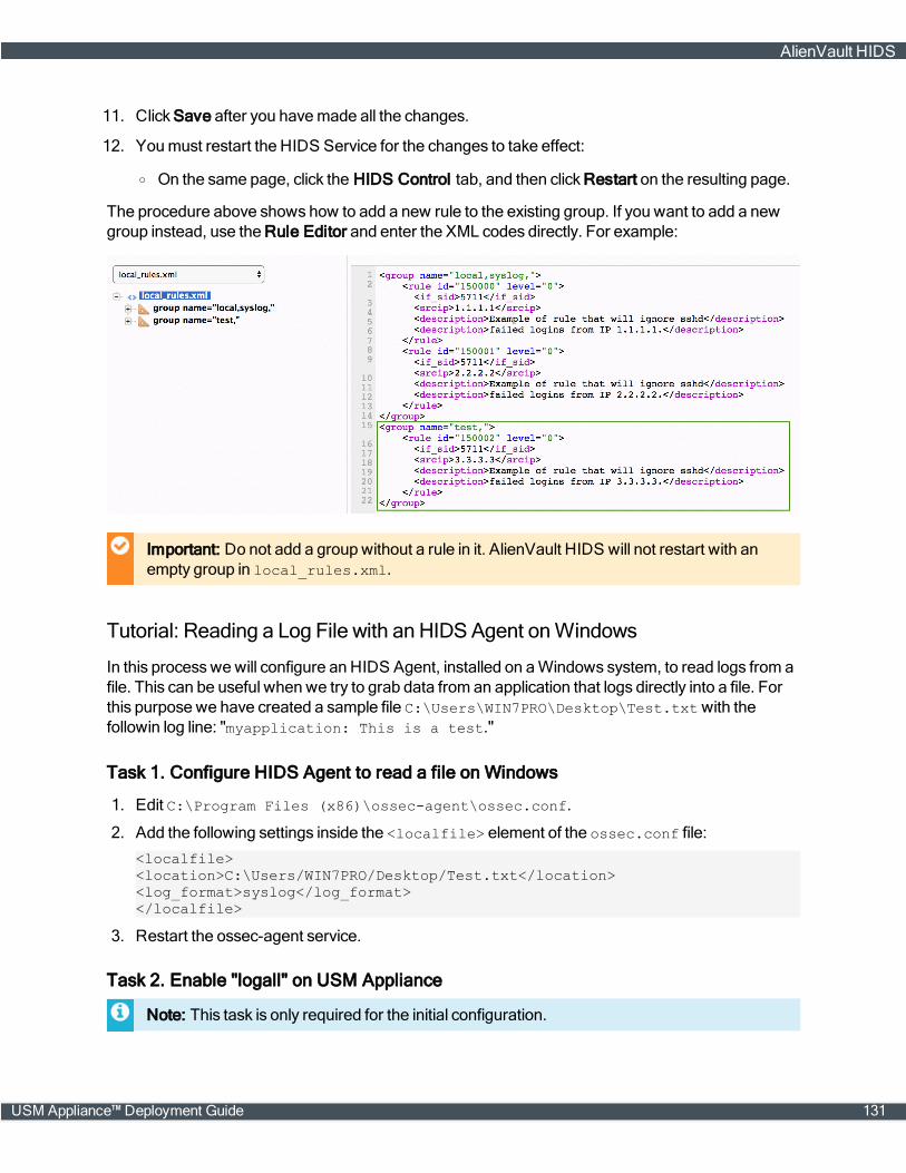
11. Click Save after you havemade all the changes.
12. Youmust restart the HIDS Service for the changes to take effect:
o On the same page, click the HIDS Control tab, and then click Restart on the resulting page.
The procedure above shows how to add a new rule to the existing group. If you want to add a newgroup instead, use the Rule Editor and enter the XML codes directly. For example:
Important: Do not add a group without a rule in it. AlienVault HIDS will not restart with anempty group in local_rules.xml.
Tutorial: Reading a Log File with an HIDSAgent onWindows
In this processwewill configure an HIDS Agent, installed on aWindows system, to read logs from afile. This can be useful when we try to grab data from an application that logs directly into a file. Forthis purpose we have created a sample file C:\Users\WIN7PRO\Desktop\Test.txtwith thefollowin log line: "myapplication: This is a test."
Task 1. Configure HIDS Agent to read a file on Windows
1. Edit C:\Program Files (x86)\ossec-agent\ossec.conf.
2. Add the following settings inside the <localfile> element of the ossec.conf file:
<localfile><location>C:\Users/WIN7PRO/Desktop/Test.txt</location><log_format>syslog</log_format></localfile>
3. Restart the ossec-agent service.
Task 2. Enable "logall" on USM Appliance
Note: This task is only required for the initial configuration.
AlienVault HIDS
USM Appliance™ Deployment Guide 131
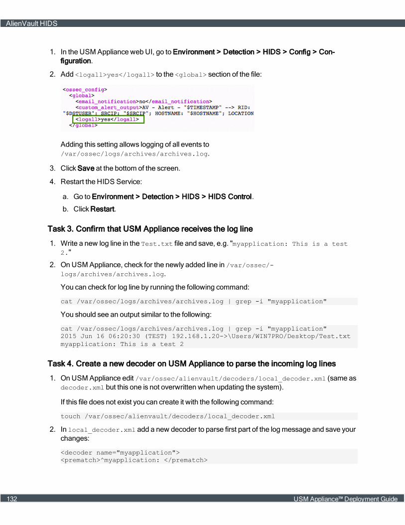
1. In the USM Appliance webUI, go to Environment > Detection > HIDS > Config > Con-figuration.
2. Add <logall>yes</logall> to the <global> section of the file:
Adding this setting allows logging of all events to/var/ossec/logs/archives/archives.log.
3. Click Save at the bottom of the screen.
4. Restart the HIDS Service:
a. Go to Environment > Detection > HIDS > HIDS Control.
b. Click Restart.
Task 3. Confirm that USM Appliance receives the log line
1. Write a new log line in the Test.txt file and save, e.g. "myapplication: This is a test2."
2. On USM Appliance, check for the newly added line in /var/ossec/-logs/archives/archives.log.
You can check for log line by running the following command:
cat /var/ossec/logs/archives/archives.log | grep -i "myapplication"
You should see an output similar to the following:
cat /var/ossec/logs/archives/archives.log | grep -i "myapplication"2015 Jun 16 06:20:30 (TEST) 192.168.1.20->\Users/WIN7PRO/Desktop/Test.txtmyapplication: This is a test 2
Task 4. Create a new decoder on USM Appliance to parse the incoming log lines
1. OnUSM Appliance edit /var/ossec/alienvault/decoders/local_decoder.xml (same asdecoder.xml but this one is not overwritten when updating the system).
If this file does not exist you can create it with the following command:
touch /var/ossec/alienvault/decoders/local_decoder.xml
2. In local_decoder.xml add a new decoder to parse first part of the logmessage and save yourchanges:
<decoder name="myapplication"><prematch>^myapplication: </prematch>
AlienVault HIDS
132 USM Appliance™ Deployment Guide
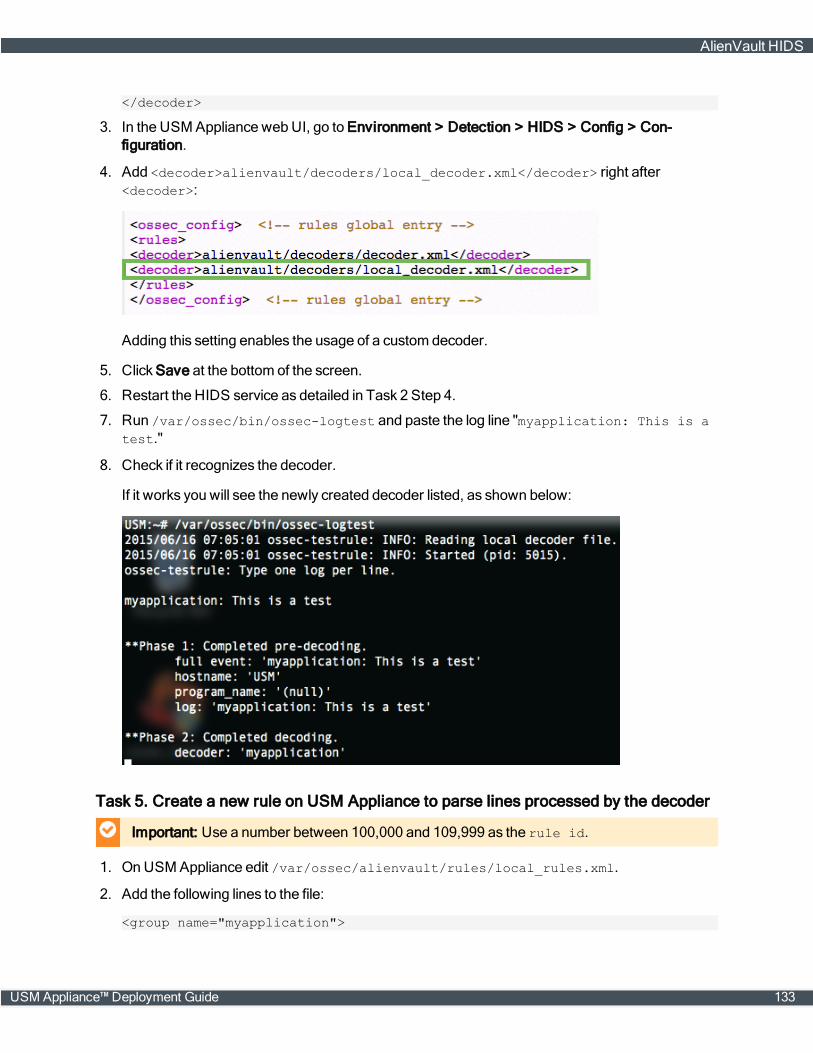
</decoder>
3. In the USM Appliance webUI, go to Environment > Detection > HIDS > Config > Con-figuration.
4. Add <decoder>alienvault/decoders/local_decoder.xml</decoder> right after<decoder>:
Adding this setting enables the usage of a custom decoder.
5. Click Save at the bottom of the screen.
6. Restart the HIDS service as detailed in Task 2 Step 4.
7. Run /var/ossec/bin/ossec-logtest and paste the log line "myapplication: This is atest."
8. Check if it recognizes the decoder.
If it works you will see the newly created decoder listed, as shown below:
Task 5. Create a new rule on USM Appliance to parse lines processed by the decoder
Important: Use a number between 100,000 and 109,999 as the rule id.
1. On USM Appliance edit /var/ossec/alienvault/rules/local_rules.xml.
2. Add the following lines to the file:
<group name="myapplication">
AlienVault HIDS
USM Appliance™ Deployment Guide 133

<rule id="106000" level="0"><decoded_as>myapplication</decoded_as><description>myapplication is enabled</description></rule>
<rule id="106001" level="1"><if_sid>106000</if_sid><match>Test</match><description>Test string found</description></rule></group>
3. Restart the HIDS service as detailed in Task 2 Step 4.
4. Run /var/ossec/bin/ossec-logtest and paste a log line (in this case "myapplication:This is another Test").
5. Check if it recognizes the rule:
You will see Phase 3 of the Log Test has completed andmatched our new rule:
Task 6. Create and configure local version of the ossec-single-line plugin
1. Create a .local version of the ossec-single-line plugin (if it does not already exist) and ensure ithas the correct owner, group and permissions:
touch /etc/ossim/agent/plugins/ossec-single-line.cfg.localchown root:alienvault /etc/ossim/agent/plugins/ossec-single-line.cfg.localchmod 644 /etc/ossim/agent/plugins/ossec-single-line.cfg.local
2. Insert or add the following translation to the ossec-single-line.cfg.local file:
[translation]106001=7999
AlienVault HIDS
134 USM Appliance™ Deployment Guide

3. Insert a new plugin_sid with value "106001" for the ossec-single-line plugin. This can be doneusing the following command:
echo 'INSERT IGNORE INTO plugin_sid(plugin_id, sid, category_id, class_id,reliability, priority, name) VALUES(7999, 106001, NULL, NULL, 1, 2,"ossec: my_application_test_rulematch");' | ossim-db
4. Run the command below to ensure the new configuration takes effect :
alienvault-reconfig
Task 7. Test your configuration
1. Generate new logs and check /var/ossec/logs/alerts/alert.logwhile the logs are beingwritten to the file:
tailf /var/ossec/logs/alerts/alerts.log | grep myapplication
You should see an output similar to the following, which confirms correct operation:
tailf /var/ossec/logs/alerts/alerts.log | grep myapplicationAV - Alert - "1434530803" --> RID: "106001"; RL: "1"; RG:"ourapplication"; RC: "Test string found"; USER: "None"; SRCIP: "None";HOSTNAME: "(TEST) 192.168.1.20->\Users/WIN7PRO/Desktop/Test.txt";LOCATION: "(TEST) 192.168.1.20->\Users/WIN7PRO/Desktop/Test.txt"; EVENT: "[INIT]myapplication: This is a test log[END]";AV - Alert - "1434530829" --> RID: "106001"; RL: "1"; RG:"ourapplication"; RC: "Test string found"; USER: "None"; SRCIP: "None";HOSTNAME: "(TEST) 192.168.1.20->\Users/WIN7PRO/Desktop/Test.txt";LOCATION: "(TEST) 192.168.1.20->\Users/WIN7PRO/Desktop/Test.txt"; EVENT: "[INIT]myapplication: This is another test log[END]";
2. (Alternatively) Generate new logs and look in theUSM Appliance webUI for results:
a. Go to Analysis > Security Events (SIEM).
b. Under Datasource, select "AlienVault HIDS".
c. ClickGrouped to view the events in groups.
You should see the newly created events with the event name: AlienVault HIDS: my_application_test_rulematch.
Task 8. Disable "logall"
Repeat all actions taken in Task 2. Enable "logall" on USM Appliance, on page 131, but this timedelete the line "<logall>yes</logall>" from ossec.conf. This is to prevent the archives.logfile from growing too large.
Task 9. (Optional) Enable File Integrity Monitoring (FIM)
For details on how to configure FIM, see File IntegrityMonitoring, on page 110.
AlienVault HIDS
USM Appliance™ Deployment Guide 135

AlienVault NIDS
l About AlienVault NIDS
l Configuring AlienVault NIDS
l Viewing AlienVault NIDS Events
l Customize AlienVault NIDS Rules
l Updating AlienVault NIDS Rules and Signatures
About AlienVault NIDS
AlienVault NIDS plays an important role in the USM Appliance. By detectingmalicious networkevents, it provides vital information for correlation directives and cross-correlation rules. Combiningthis information with the events collected from other devices, USM Appliance presents a completepicture of themalicious activity.
The AlienVault NIDS functionality, includingmonitoring network traffic and detectingmaliciousevents, takes place on the USM Appliance Sensor. You should configure at least two networkinterfaces on a USM Appliance Sensor or USM Appliance All-in-One:
n Management interface — Configure the interface with an IP address, which you can reach fromthe network. Use this interface for administrative purposes and communication with otherUSM Appliance components. See Set Up theManagement Interface, on page 68.
n Networkmonitoring interface — Do not configure an IP address on the interface. Instead, connectthe interface to a spanned or mirrored port on a network switch , so that USM Appliance canexamine the throughput. You can usemore than one networkmonitoring interface to observe sev-eral networks from a single USM Appliance Sensor. See Configuring AlienVault NIDS, on page137.
The USM Appliance Server consumes the NIDS signatures through plugins, which generates theAlienVault NIDS events. The correlation engine processes and correlates the normalized events,then stores them in the SIEM database.
AlienVault NIDS
136 USM Appliance™ Deployment Guide
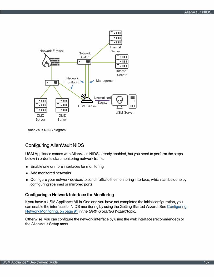
AlienVault NIDS diagram
Configuring AlienVault NIDS
USM Appliance comeswith AlienVault NIDS already enabled, but you need to perform the stepsbelow in order to start monitoring network traffic:
n Enable one or more interfaces for monitoring
n Addmonitored networks
n Configure your network devices to send traffic to themonitoring interface, which can be done byconfiguring spanned or mirrored ports
Configuring a Network Interface for Monitoring
If you have a USM Appliance All-in-One and you have not completed the initial configuration, youcan enable the interface for NIDS monitoring by using theGetting StartedWizard. See ConfiguringNetworkMonitoring, on page 91 in the Getting StartedWizard topic.
Otherwise, you can configure the network interface by using the web interface (recommended) orthe AlienVault Setupmenu.
AlienVault NIDS
USM Appliance™ Deployment Guide 137
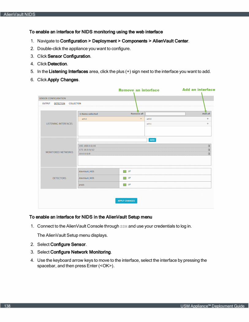
To enable an interface for NIDS monitoring using the web interface
1. Navigate to Configuration > Deployment > Components > AlienVault Center.
2. Double-click the appliance you want to configure.
3. Click Sensor Configuration.
4. Click Detection.
5. In the Listening Interfaces area, click the plus (+) sign next to the interface you want to add.
6. Click Apply Changes.
To enable an interface for NIDS in the AlienVault Setup menu
1. Connect to the AlienVault Console through SSH and use your credentials to log in.
The AlienVault Setupmenu displays.
2. Select Configure Sensor.
3. Select Configure Network Monitoring.
4. Use the keyboard arrow keys tomove to the interface, select the interface by pressing thespacebar, and then press Enter (<OK>).
AlienVault NIDS
138 USM Appliance™ Deployment Guide
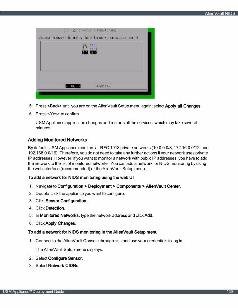
5. Press <Back> until you are on the AlienVault Setupmenu again; select Apply all Changes.
6. Press <Yes> to confirm.
USMAppliance applies the changes and restarts all the services, whichmay take severalminutes.
Adding Monitored Networks
By default, USM Appliancemonitors all RFC 1918 private networks (10.0.0.0/8, 172.16.0.0/12, and192.168.0.0/16). Therefore, you do not need to take any further actions if your network uses privateIP addresses. However, if you want to monitor a network with public IP addresses, you have to addthe network to the list of monitored networks. You can add a network for NIDS monitoring by usingthe web interface (recommended) or the AlienVault Setupmenu.
To add a network for NIDS monitoring using the web UI
1. Navigate to Configuration > Deployment > Components > AlienVault Center.
2. Double-click the appliance you want to configure.
3. Click Sensor Configuration.
4. Click Detection.
5. In Monitored Networks, type the network address and click Add.
6. Click Apply Changes.
To add a network for NIDS monitoring in the AlienVault Setup menu
1. Connect to the AlienVault Console through SSH and use your credentials to log in.
The AlienVault Setupmenu displays.
2. Select Configure Sensor.
3. Select Network CIDRs.
AlienVault NIDS
USM Appliance™ Deployment Guide 139
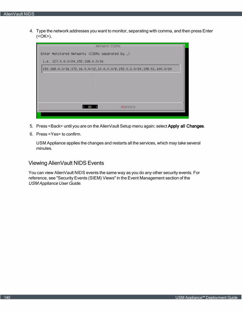
4. Type the network addresses you want to monitor, separating with comma, and then press Enter(<OK>).
5. Press <Back> until you are on the AlienVault Setupmenu again; select Apply all Changes.
6. Press <Yes> to confirm.
USMAppliance applies the changes and restarts all the services, whichmay take severalminutes.
Viewing AlienVault NIDSEvents
You can view AlienVault NIDS events the sameway as you do any other security events. Forreference, see "Security Events (SIEM) Views" in the Event Management section of theUSM Appliance User Guide.
AlienVault NIDS
140 USM Appliance™ Deployment Guide
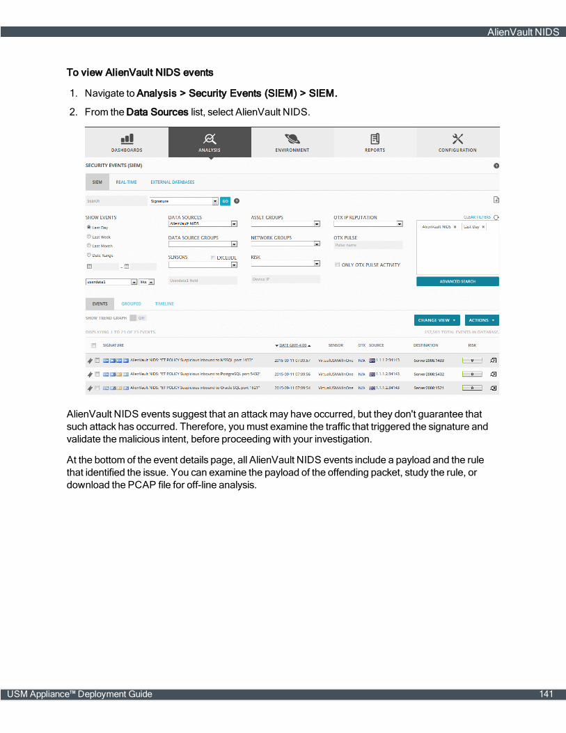
To view AlienVault NIDS events
1. Navigate to Analysis > Security Events (SIEM) > SIEM.
2. From the Data Sources list, select AlienVault NIDS.
AlienVault NIDS events suggest that an attackmay have occurred, but they don't guarantee thatsuch attack has occurred. Therefore, youmust examine the traffic that triggered the signature andvalidate themalicious intent, before proceeding with your investigation.
At the bottom of the event details page, all AlienVault NIDS events include a payload and the rulethat identified the issue. You can examine the payload of the offending packet, study the rule, ordownload the PCAP file for off-line analysis.
AlienVault NIDS
USM Appliance™ Deployment Guide 141
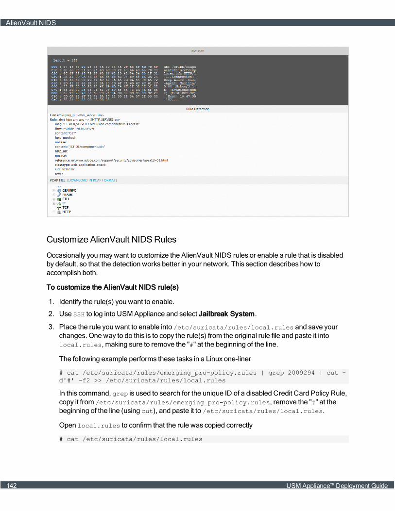
Customize AlienVault NIDSRules
Occasionally youmaywant to customize the AlienVault NIDS rules or enable a rule that is disabledby default, so that the detection works better in your network. This section describes how toaccomplish both.
To customize the AlienVault NIDS rule(s)
1. Identify the rule(s) you want to enable.
2. Use SSH to log into USM Appliance and select Jailbreak System.
3. Place the rule you want to enable into /etc/suricata/rules/local.rules and save yourchanges. One way to do this is to copy the rule(s) from the original rule file and paste it intolocal.rules, making sure to remove the "#" at the beginning of the line.
The following example performs these tasks in a Linux one-liner
# cat /etc/suricata/rules/emerging_pro-policy.rules | grep 2009294 | cut -d'#' -f2 >> /etc/suricata/rules/local.rules
In this command, grep is used to search for the unique ID of a disabled Credit Card Policy Rule,copy it from /etc/suricata/rules/emerging_pro-policy.rules, remove the "#" at thebeginning of the line (using cut), and paste it to /etc/suricata/rules/local.rules.
Open local.rules to confirm that the rule was copied correctly
# cat /etc/suricata/rules/local.rules
AlienVault NIDS
142 USM Appliance™ Deployment Guide
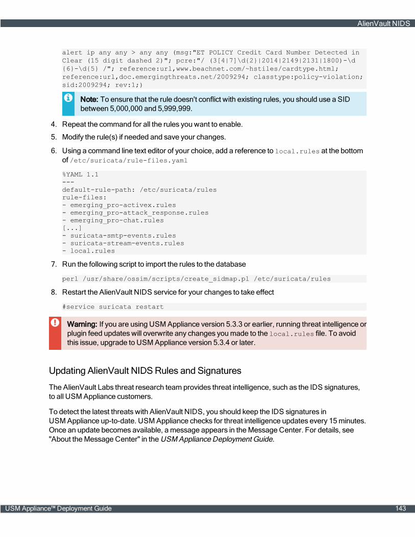
alert ip any any > any any (msg:"ET POLICY Credit Card Number Detected inClear (15 digit dashed 2)"; pcre:"/ (3[4|7]\d{2}|2014|2149|2131|1800)-\d{6}-\d{5} /"; reference:url,www.beachnet.com/~hstiles/cardtype.html;reference:url,doc.emergingthreats.net/2009294; classtype:policy-violation;sid:2009294; rev:1;)
Note: To ensure that the rule doesn't conflict with existing rules, you should use a SIDbetween 5,000,000 and 5,999,999.
4. Repeat the command for all the rules you want to enable.
5. Modify the rule(s) if needed and save your changes.
6. Using a command line text editor of your choice, add a reference to local.rules at the bottomof /etc/suricata/rule-files.yaml
%YAML 1.1---default-rule-path: /etc/suricata/rulesrule-files:- emerging_pro-activex.rules- emerging_pro-attack_response.rules- emerging_pro-chat.rules[...]- suricata-smtp-events.rules- suricata-stream-events.rules- local.rules
7. Run the following script to import the rules to the database
perl /usr/share/ossim/scripts/create_sidmap.pl /etc/suricata/rules
8. Restart the AlienVault NIDS service for your changes to take effect
#service suricata restart
Warning: If you are using USM Appliance version 5.3.3 or earlier, running threat intelligence orplugin feed updateswill overwrite any changes youmade to the local.rules file. To avoidthis issue, upgrade to USM Appliance version 5.3.4 or later.
Updating AlienVault NIDSRules and Signatures
The AlienVault Labs threat research team provides threat intelligence, such as the IDS signatures,to all USM Appliance customers.
To detect the latest threats with AlienVault NIDS, you should keep the IDS signatures inUSM Appliance up-to-date. USM Appliance checks for threat intelligence updates every 15minutes.Once an update becomes available, amessage appears in theMessage Center. For details, see"About theMessage Center" in the USM Appliance Deployment Guide.
AlienVault NIDS
USM Appliance™ Deployment Guide 143
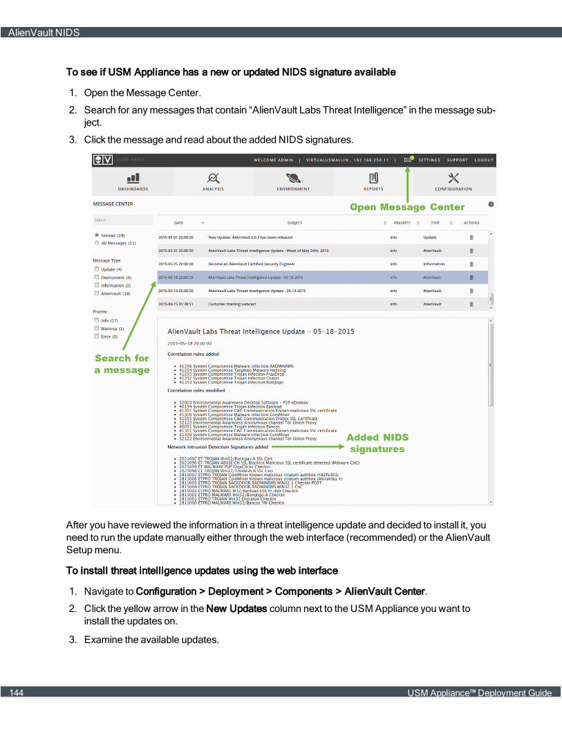
To see if USM Appliance has a new or updated NIDS signature available
1. Open theMessage Center.
2. Search for anymessages that contain “AlienVault Labs Threat Intelligence” in themessage sub-ject.
3. Click themessage and read about the added NIDS signatures.
After you have reviewed the information in a threat intelligence update and decided to install it, youneed to run the updatemanually either through the web interface (recommended) or the AlienVaultSetupmenu.
To install threat intelligence updates using the web interface
1. Navigate to Configuration > Deployment > Components > AlienVault Center.
2. Click the yellow arrow in the New Updates column next to the USM Appliance you want toinstall the updates on.
3. Examine the available updates.
AlienVault NIDS
144 USM Appliance™ Deployment Guide
NIDS updates contain “suricata” in the package name.
4. Click Update Feed Only.
Note: This updates signatures and rules for all packages listed in the update summary, notjust the IDS signatures.
The upgrade process can take several minutes. After completion, the page displays amessageindicating a successful update.
To install threat intelligence updates in the AlienVault Setup Menu
1. Launch the AlienVault console.
2. Select System Preferences; press Enter (<OK>).
3. Select Update AlienVault System; press Enter (<OK>).
4. Select Update Threat Intelligence; press Enter (<OK>).
5. Confirm your selection.
Note: The AlienVault console does not show the list of available updates, but you cancheck the update progress.
The upgrade process can take several minutes. After completion, the console displays amessageindicating a successful update.
AlienVault NIDS
USM Appliance™ Deployment Guide 145
VPNConfiguration
This section covers the following subtopics:
About Configuring a Virtual Private Network 147
Configuring a VPN Between USM Appliance Systems 147
Building a VPN TunnelWithout a Client-Server Connection 151
Verifying the VPN Connection 154
Disabling a VPN Configuration 154
USM Appliance™ Deployment Guide 146

About Configuring a Virtual Private Network
Establishing a Virtual Private Network (VPN) connection between AlienVault USM Appliancecomponents encrypts all network traffic that passes through a secure VPN tunnel.
The AlienVault VPN environment consists of a single VPN server that connects to at least one, butusuallymultiple, VPN clients.
Typically, you configure a USM Appliance Standard or Enterprise Server, or an USM Appliance All-in-One, to act as the VPN server. But, in theory, any AlienVault appliance can serve this function.
Important: An AlienVault appliance cannot serve both as a VPN server and a VPN client at thesame time.
Prerequisites
Youmust have already cabled and set up your USM Appliance Server, USM Appliance Sensor, andUSM Appliance Logger appliances, with one exception. If you intend for one of your sensors orloggers to act as the VPN client, you only complete setup up to, but not including, the tasks inConfigure the USM Appliance Sensor after Deployment, on page 63 or Configure theUSM Appliance Logger after Deployment, on page 64, as applicable.
Note: Completion of the appliance registration task enables viewing of all of the VPN-relatedconfiguration options in the AlienVault Setupmenu.
Before completing that configuration task, youmust have first created a VPN tunnel between theVPN server and VPN client. This gives you the VPN IP address required to configure the sensor orlogger in that role.
Configuring a VPN Between USM Appliance Systems
To set up a VPN between two USM Appliance components, for example, between aUSM Appliance All-in-One and a USM Appliance Sensor, or between a USM Appliance Server anda USM Appliance Logger, you need to configure through the AlienVault Setupmenu, on the SystemPreferences > Configure Network > Setup VPN screen:
About Configuring a Virtual Private Network
147 USM Appliance™ Deployment Guide
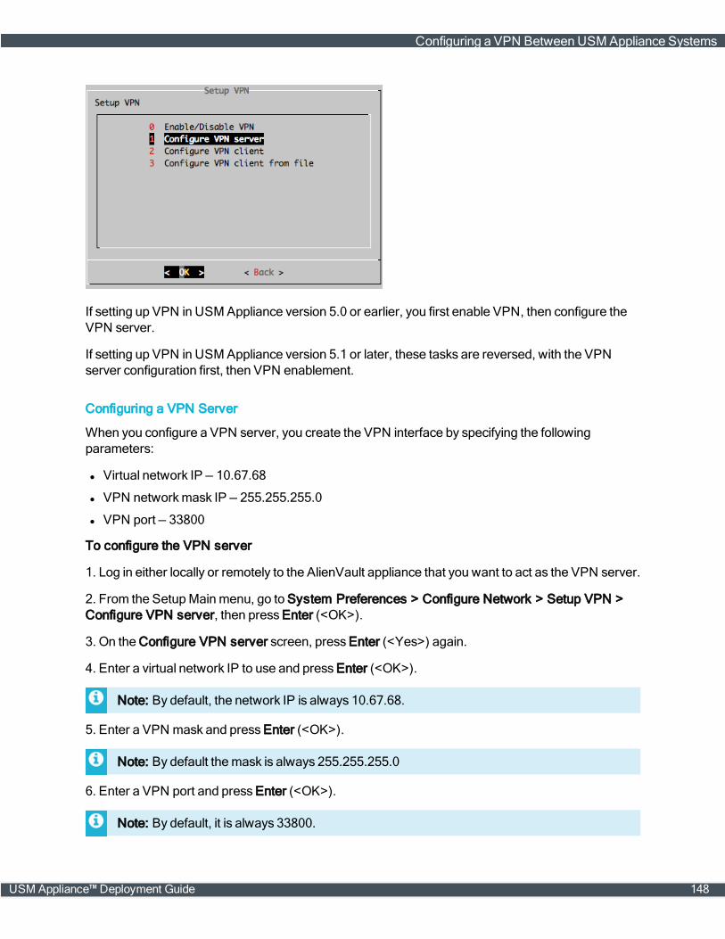
If setting up VPN in USM Appliance version 5.0 or earlier, you first enable VPN, then configure theVPN server.
If setting up VPN in USM Appliance version 5.1 or later, these tasks are reversed, with the VPNserver configuration first, then VPN enablement.
Configuring a VPN Server
When you configure a VPN server, you create the VPN interface by specifying the followingparameters:
l Virtual network IP — 10.67.68
l VPN networkmask IP — 255.255.255.0
l VPN port — 33800
To configure the VPN server
1. Log in either locally or remotely to the AlienVault appliance that you want to act as the VPN server.
2. From the SetupMainmenu, go to System Preferences > Configure Network > Setup VPN >Configure VPN server, then press Enter (<OK>).
3. On the Configure VPN server screen, press Enter (<Yes>) again.
4. Enter a virtual network IP to use and press Enter (<OK>).
Note: By default, the network IP is always 10.67.68.
5. Enter a VPN mask and press Enter (<OK>).
Note: By default themask is always 255.255.255.0
6. Enter a VPN port and press Enter (<OK>).
Note: By default, it is always 33800.
Configuring a VPN Between USM Appliance Systems
USM Appliance™ Deployment Guide 148

7. Use the <Back> option and press Enter until the AlienVault Setupmenu reappears.
8. Go to Apply all Changes and press Enter (<OK>):
9. Press Enter (<Yes>) to confirm.
The system applies the changes and restart the services, then console displays: ChangesApplied.
10. Press Enter (<OK>).
Enabling VPN
To enable the VPN
1. From the AlienVault SetupMainmenu, go to System Preferences > Configure Network >Setup VPN > Enable/Disable VPN, then press Enter (<OK>).
2. Use the arrow keys tomove the asterisk(*) to "yes", press the spacebar to select, and then pressEnter (<OK>).
Configuring a VPN Between USM Appliance Systems
149 USM Appliance™ Deployment Guide
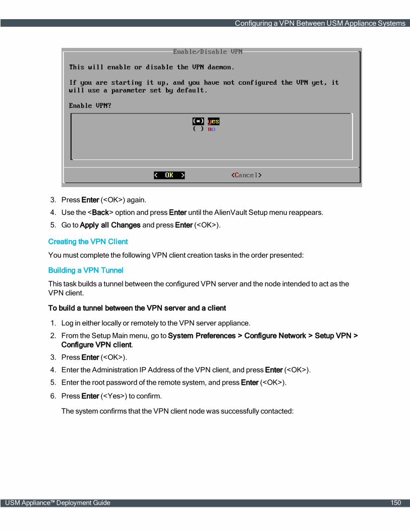
3. Press Enter (<OK>) again.
4. Use the <Back> option and press Enter until the AlienVault Setupmenu reappears.
5. Go to Apply all Changes and press Enter (<OK>).
Creating the VPN Client
Youmust complete the following VPN client creation tasks in the order presented:
Building a VPN Tunnel
This task builds a tunnel between the configured VPN server and the node intended to act as theVPN client.
To build a tunnel between the VPN server and a client
1. Log in either locally or remotely to the VPN server appliance.
2. From the SetupMainmenu, go to System Preferences > Configure Network > Setup VPN >Configure VPN client.
3. Press Enter (<OK>).
4. Enter the Administration IP Address of the VPN client, and press Enter (<OK>).
5. Enter the root password of the remote system, and press Enter (<OK>).
6. Press Enter (<Yes>) to confirm.
The system confirms that the VPN client node was successfully contacted:
Configuring a VPN Between USM Appliance Systems
USM Appliance™ Deployment Guide 150

Note: Make note of the VPN IP address, because you will need it for the clientconfiguration task.
7. To continue, press Enter.
If the tunnel creation process does not finish successfully, the followingmessage appears instead:
In this case, see Building a VPN TunnelWithout a Client-Server Connection, on page 151.
Completing the VPN Client Configuration
If the VPN client you are configuring is a USM Appliance Sensor or USM Appliance Logger, youneed to finish the configuration by performing some additional steps. Click the corresponding linkbelow for details.
Important: Make sure to use the VPN IP address you noted from the output in step 6 inbuilding a VPN tunnel.
l Configure the USM Appliance Sensor after Deployment, on page 63
l Configure the USM Appliance Logger after Deployment, on page 64
Building a VPN Tunnel Without a Client-Server Connection
If there is no connection between the VPN server and the client, which is often the case in anMSSP(Managed Security Service Provider) environment, an error occurs when you try to configure theclient:
Building the VPN node configuration...Restarting OpenVPN server...Retrieving the local vpn server ip...Trying to deploy the VPN configuration on the remote AlienVault appliance...An error occurred while establishing the vpn tunnel:
Building a VPN TunnelWithout a Client-Server Connection
151 USM Appliance™ Deployment Guide
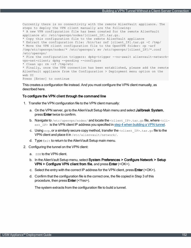
Currently there is no connectivity with the remote AlienVault appliance. Thesteps to deploy the VPN client manually are the following:* A new VPN configuration file has been created for the remote AlienVaultappliance at: /etc/openvpn/nodes/[client_IP].tar.gz.* Copy this configuration file to the remote AlienVault appliance* Extract the configuration file: /bin/tar zxf [client_IP].tar.gz -C /tmp/* Move the VPN client configuration file to the OpenVPN folder: cp -arf/tmp/etc/openvpn/nodes/* /etc/openvpn/; mv /etc/openvpn/[client_IP]/*.conf/etc/openvpn/* Fire the configuration triggers: dpkg-trigger --no-await alienvault-network-vpn-net-client; dpkg --pending --configure* Clean up: rm -rf /tmp/etc* Finally, once the VPN connection has been established, please add the remoteAlienVault appliance from the Configuration > Deployment menu option on theweb UIPress [Enter] to continue
This creates a configuration file instead. And youmust configure the VPN client manually, asdescribed here.
To configure the VPN client through the command line
1. Transfer the VPN configuration file to the VPN client manually:
a. On the VPN server, go to the AlienVault SetupMainmenu and select Jailbreak System,press Enter twice to confirm.
b. Navigate to /etc/openvpn/nodes/ and locate the <client_IP>.tar.gz file, where <cli-ent_IP> is the VPN client IP address you specified in step 4 when building a VPN tunnel.
c. Using scp, or a similarly secure copymethod, transfer the <client_IP>.tar.gz file to theVPN client and place it in /etc/alienvault/network/.
d. Type Exit to return to the AlienVault Setupmainmenu.
2. Configuring the tunnel on the VPN client:
a. SSH to the VPN client.
b. In the AlienVault Setupmenu, select System Preferences > Configure Network > SetupVPN > Configure VPN client from file, and press Enter (<OK>).
c. Select the entry with the correct IP address for the VPN client, press Enter (<OK>).
d. Confirm that the configuration file is the correct one, the file copied in Step 3 of thisprocedure, then press Enter (<Yes>).
The system extracts from the configuration file to build a tunnel.
Building a VPN TunnelWithout a Client-Server Connection
USM Appliance™ Deployment Guide 152

Additional StepWhen the VPN server and VPN client Reside in DifferentNetworks
Please be aware that if the VPN client and VPN server are in different private networks and theconnection from the VPN client to the VPN server is only allowed through their public IP addresses,you need to change the IP address in the configuration file manually.
Let's consider the following example, where the VPN server and VPN client have different privatethe public IP addresses:
VPN server VPN client
Private IP 192.168.0.1 172.16.20.56
Public IP 88.132.33.11 145.156.44.33
Sample IP addresses for the VPN server and VPN client
When configuring the VPN client, enter the public IP address for the client, in this case145.156.44.33. Extract the resulting /etc/openvpn/nodes/145.156.44.33.tar.gz file andlocate the VPN client configuration file, 145.156.44.33.conf. Observe that the private IP addressof the VPN server (192.168.0.1) is added instead of the public IP address, as indicated in line 4below:
clientdev tunproto tcpremote 192.168.0.1 33800resolv-retry infinitenobinduser nobodygroup nogroupverb 3ca /etc/openvpn/145.156.44.33/ca.crtcert /etc/openvpn/145.156.44.33/145.156.44.33.crtkey /etc/openvpn/145.156.44.33/145.156.44.33.keyscript-security 2 systemup "/etc/init.d/fprobe stop || true"comp-lzopersist-keypersist-tun
This causes the VPN tunnel not be established. Changing the IP address to 88.132.33.11 in thefile above resolves this issue.
Building a VPN TunnelWithout a Client-Server Connection
153 USM Appliance™ Deployment Guide

Verifying the VPN Connection
To verify the VPN connection
1. Open a browser window, using the VPN server IP, and log into USM Appliance with admin-istrator credentials.
2. Go to Configuration > Deployment > Components and verify that the components display aVPN IP address:
This verifies that your VPN connection is intact.
Disabling a VPN Configuration
When you disable a VPN tunnel, it does not remove the configuration files and system-generatedcertificates from the appliance. You can enable the same tunnel again, if needed.
If you decide instead to establish a new VPN tunnel on the same AlienVault appliance, repeat theprocedures. The system then overwrites the existing configurations.
You can disable a VPN configuration from either the VPN server or a VPN client.
To disable a VPN configuration
1. Connect to the AlienVault Console through SSH and use your credentials to log in.
The AlienVault Setupmenu displays.
2. Select System Preferences.
3. Select Configure Network.
4. Select Setup VPN.
5. Select Enable/Disable VPN.
6. Use the arrow keys tomove to "no", press the spacebar to select, and then press Enter (<OK>).
7. Press <Back> until you are on the AlienVault Setupmenu again; select Apply all Changes.
Verifying the VPN Connection
USM Appliance™ Deployment Guide 154
8. Press <Yes> to confirm.
USMAppliance applies the changes and restarts all the services, whichmay take severalminutes.
Disabling a VPN Configuration
155 USM Appliance™ Deployment Guide

High Availability Configuration
This section covers the following subtopics:
About High Availability 157
High Availability Prerequisites and Restrictions 158
Configuring High Availability in USM Appliance Standard Systems 160
Configuring High Availability in USM Appliance Enterprise Systems 172
Disabling High Availability 175
Upgrading a USM Appliance Deployment Configured for High Availability 176
USM Appliance™ Deployment Guide 156

About High Availability
This topic describes the value of high availability to your company and what high availability (HA)means in the AlienVault USM Appliance context.
WhyConfigure High Availability?
High availability (HA) replicates data to avoid any potential loss of events, assets, or configurationsshould one or more components cease operation for any reason.
AlienVault strongly recommends that you configure USM Appliance for high availability, particularly,for compliance requirements, so that no data are lost.
Note: AlienVault USM Appliance supports HA only in its USM Appliance Standard andUSM Appliance Enterprise products.
HowDoes the High Availability SolutionWork?
The AlienVault USM Appliance high availability solution consists of a set of redundantUSM Appliance nodes that mirror each other.
This HA system remains operational, with the primary (master) instance being active and thesecondary (slave) instance, passive. If the primary instance fails, the secondary instance becomesactive automatically, replacing the failed node.
Active (left) and passive (right) nodes for a USM Appliance system component
When you are ready to bring the failed node back on line, it again becomes the active node and thenode that took its place reverts to being the passive node. Usersmust make the switchmanually.
Each node has a unique IP address, but shares the same virtual IP addresswith its clone.
The HA deployment always starts with the USM Appliance Server and the USM Appliance Sensor.If the USM Appliance Logger is part of your USM Appliance deployment, you should configure it last.
About High Availability
157 USM Appliance™ Deployment Guide

Typical HA topology, including loggers
High Availability Prerequisites and Restrictions
Before you start, review the prerequisites and restrictions in setting up a high availability (HA)USM Appliance system.
General Prerequisites and Restrictions
Make sure that you review all of the following AlienVault USM Appliance HA requirements andrestrictions carefully before starting your deployment:
l Because this HA feature does not work across dispersed locations (due to their different IPaddressing), both the primary and secondary systemsmust be on the same subnet.
l To avoid any network failures that could affect USM Appliance high availability, nodesmust beconnected through a dedicated network cable, without any networking equipment.
l Rack and cable two nodes for each USM Appliance, as described in the solution you deploy.
l Use Isolated interfaces (for example, eth1) at each node.
High Availability Prerequisites and Restrictions
USM Appliance™ Deployment Guide 158
l Make sure that the primary and secondary nodes are running the same image of AlienVaultUSM Appliance. For example, if the primary node is updated to USM Applianceversion 5.3 froma previous version but the secondary node is a fresh install of USM Applianceversion 5.3, HA willnot work properly.
NTP Server Requirements
l Both the primary and secondary nodes require their own dedicated NTP Server. TheseNTP Servers should be configured identically.
l Both NTP Serversmust be up and running, and synchronized with each other.
Configuration Prerequisites — USM Appliance Standard and EnterpriseSolutions
These prerequisites and restrictions apply both to the USM Appliance Standard and Enterprisedeployments.
l The primary and secondary nodes of a USM Appliance component in an HA deployment cannotshare the same hostname.
l You cannot change the IP or hostname of any component in a high availability system once con-figured.
l Youmust register both nodes of each component.
l Both the primary and secondary instancesmust have the same time zone setting.
l Make sure that you configure each node to communicate with the NTP Server for its instance.
Configuration Prerequisites — USM Appliance Enterprise Solution Only
Youmust configure both nodes for the USM Appliance Enterprise Server and the USM ApplianceEnterprise Database with the same root password.
General Maintenance Prerequisites
l Make sure that you always keep the secondary HA instance at parity with the primaryUSM Appliance instance.
l When upgrading USM Appliance to a new version, HA must be disabled. Otherwise, you lose theHA configuration. You can re-enable HA when the upgrade has finished.
Important: Any network latency or network disconnection issues that can lead to replicationfailuremust be fixed promptly.
High Availability Prerequisites and Restrictions
159 USM Appliance™ Deployment Guide

Configuring High Availability in USM Appliance Standard Systems
Before You Start
1. Carefully review High Availability Prerequisites and Restrictions, on page 158.
2. Deploy two instances for each USM Appliance component (USM Appliance Standard Server,USM Appliance Standard Sensor, or, if used, USM Appliance Standard Logger), as describedin USMAppliance Deployments, on page 34.
Configuring High Availability for USM Appliance Standard Servers
TheUSM Appliance Standard Server is the first USM Appliance component that youmust configurefor HA.
See also Example: Configuring High Availability for USM Appliance Standard Servers, on page 162.
Youmust first deploy and configure the node you intend to act as the passive node, or slave. Youconfigure the active, or master, node, second. Both procedures appear below.
Configuring the Secondary Standard Server for HA
To configure HA in the secondary server
1. Log into the secondary (slave) Standard Server.
2. From the AlienVault SetupMainmenu, select Jailbreak System and press Enter (<OK>).
3. Press Enter (<Yes>) to continue.
4. When you see the command line prompt, access and edit the file /etc/ossim/ossim_setup.conf as indicated in the angle-bracketed variables below:
ha_heartbeat_start=yesha_local_node_ip=<slave_appliance_IP>ha_other_node_ip=<master_appliance_IP>ha_other_node_name=<master_appliance_name>ha_password=<password>**This password must be the same for both slave and master.**ha_role=slaveha_virtual_ip=<virtual_IP>
Important: The ha_role valuemust always equal "slave" for the secondary node.
5. Save the changes.
6. Enable HA in the slave by entering the following command:
screen alienvault-ha-assistant -e
Note: Use screen to keep the process running in the background even when the sessiondisconnects.
Configuring High Availability in USM Appliance Standard Systems
USM Appliance™ Deployment Guide 160
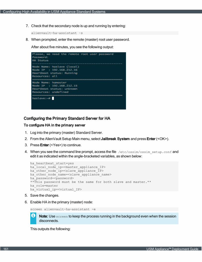
7. Check that the secondary node is up and running by entering:
alienvault-ha-assistant –s
8. When prompted, enter the remote (master) root user password.
After about fiveminutes, you see the following output:
Configuring the Primary Standard Server for HA
To configure HA in the primary server
1. Log into the primary (master) Standard Server.
2. From the AlienVault SetupMainmenu, select Jailbreak System and press Enter (<OK>).
3. Press Enter (<Yes>) to continue.
4. When you see the command line prompt, access the file /etc/ossim/ossim_setup.conf andedit it as indicated within the angle-bracketed variables, as shown below:
ha_heartbeat_start=yesha_local_node_ip=<master_appliance_IP>ha_other_node_ip=<slave_appliance_IP>ha_other_node_name=<slave_appliance_name>ha_password=<password>**This password must be the same for both slave and master.**ha_role=masterha_virtual_ip=<virtual_IP>
5. Save the changes.
6. Enable HA in the primary (master) node:
screen alienvault-ha-assistant -e
Note: Use screen to keep the process running in the background even when the sessiondisconnects.
This outputs the following:
Configuring High Availability in USM Appliance Standard Systems
161 USM Appliance™ Deployment Guide
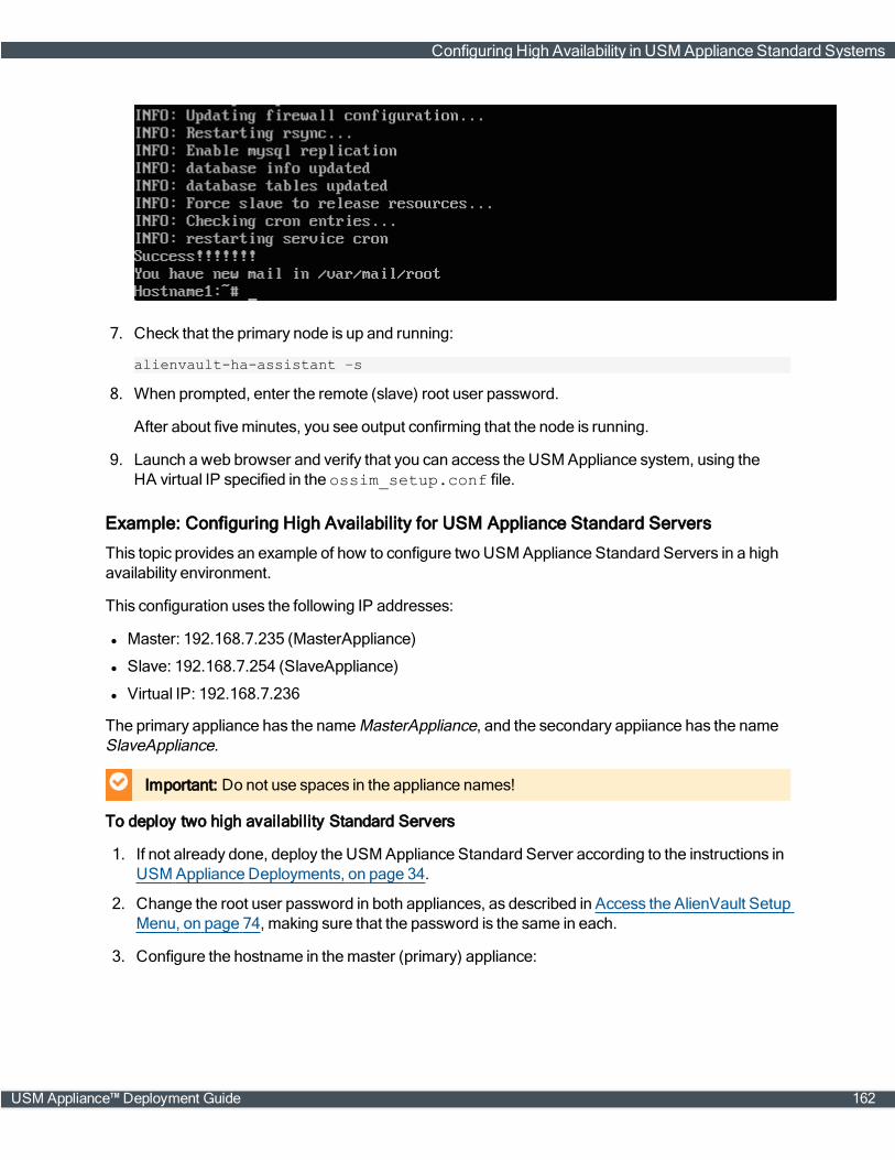
7. Check that the primary node is up and running:
alienvault-ha-assistant –s
8. When prompted, enter the remote (slave) root user password.
After about fiveminutes, you see output confirming that the node is running.
9. Launch a web browser and verify that you can access the USM Appliance system, using theHA virtual IP specified in the ossim_setup.conf file.
Example: Configuring High Availability for USM Appliance Standard Servers
This topic provides an example of how to configure two USM Appliance Standard Servers in a highavailability environment.
This configuration uses the following IP addresses:
l Master: 192.168.7.235 (MasterAppliance)
l Slave: 192.168.7.254 (SlaveAppliance)
l Virtual IP: 192.168.7.236
The primary appliance has the nameMasterAppliance, and the secondary appiiance has the nameSlaveAppliance.
Important: Do not use spaces in the appliance names!
To deploy two high availability Standard Servers
1. If not already done, deploy the USM Appliance Standard Server according to the instructions inUSMAppliance Deployments, on page 34.
2. Change the root user password in both appliances, as described in Access the AlienVault SetupMenu, on page 74, making sure that the password is the same in each.
3. Configure the hostname in themaster (primary) appliance:
Configuring High Availability in USM Appliance Standard Systems
USM Appliance™ Deployment Guide 162
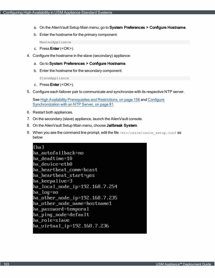
a. On the AlienVault SetupMainmenu, go to System Preferences > Configure Hostname.
b. Enter the hostname for the primary component:
MasterAppliance
c. Press Enter (<OK>).
4. Configure the hostname in the slave (secondary) appliance:
a. Go to System Preferences > Configure Hostname.
b. Enter the hostname for the secondary component:
SlaveAppliance
c. Press Enter (<OK>).
5. Configure each failover pair to communicate and synchronize with its respective NTP server.
See High Availability Prerequisites and Restrictions, on page 158 and ConfigureSynchronization with an NTP Server, on page 81.
6. Restart both appliances.
7. On the secondary (slave) appliance, launch the AlienVault console.
8. On the AlienVault SetupMainmenu, choose Jailbreak System.
9. When you see the command line prompt, edit the file /etc/ossim/ossim_setup.conf asbelow
Configuring High Availability in USM Appliance Standard Systems
163 USM Appliance™ Deployment Guide

10. Save the changes.
11. Enable HA in the secondary node by entering:
screen alienvault-ha-assistant -e
Note: Use screen to keep the process running in the background even when the sessiondisconnects.
12. Check that the secondary node is up and running:
alienvault-ha-assistant –s
13. When prompted, enter the root user password for the primary (master) server.
After about fiveminutes, you see output, showing HA status for the secondary (slave) heartbeatstatus should be Running.
14. On the primary (master) appliance, log into the AlienVault console.
15. On the AlienVault SetupMainmenu, choose Jailbreak System.
16. Edit the /etc/ossim/ossim_setup.conf file as below
17. Save the changes.
18. Enable HA in the primary node:
screen alienvault-ha-assistant -e
Note: Use screen to keep the process running in the background even when the sessiondisconnects.
19. Verify that the primary node is up and running:
alienvault-ha-assistant –s
Configuring High Availability in USM Appliance Standard Systems
USM Appliance™ Deployment Guide 164

20. When prompted, enter the root user password for the secondary server.
After about fiveminutes, you see output, showing HA status for the secondary (slave) heartbeatstatus asRunning.
21. Launch a web browser, check that you can access the USM Appliance Standard Serverthrough the ha_virtual_ip assigned in the ossim_setup.conf file.
It should look like the following:
Configuring High Availability for USM Appliance Standard Sensors
This process has three tasks you perform in the following order:
l Configuring the Secondary Standard Sensor for HA, on page 165
l Configuring the Primary Standard Sensor for HA, on page 166
l Configuring Communication Between the Standard Sensors and the Standard Servers, on page167
Configuring the Secondary Standard Sensor for HA
To configure a secondary sensor in HA
1. Log into the secondary Standard Sensor.
2. From the AlienVault SetupMainmenu, select Jailbreak System and press Enter (<OK>).
3. Press Enter (<Yes>) to continue.
The command line prompt appears.
Configuring High Availability in USM Appliance Standard Systems
165 USM Appliance™ Deployment Guide
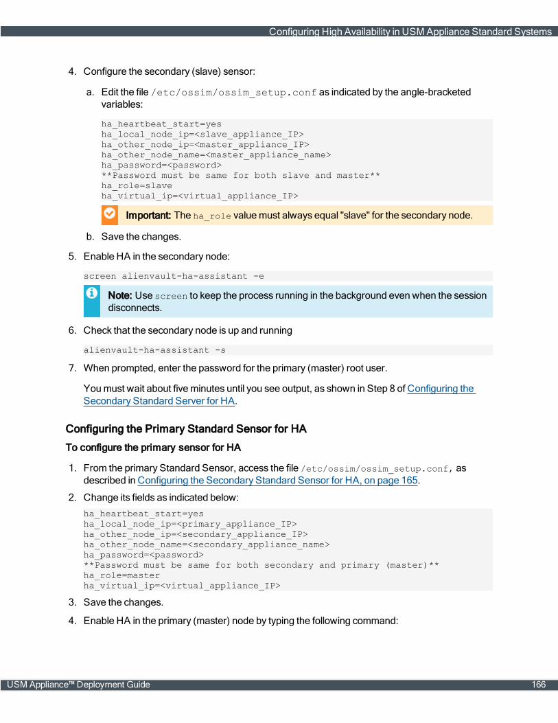
4. Configure the secondary (slave) sensor:
a. Edit the file /etc/ossim/ossim_setup.conf as indicated by the angle-bracketedvariables:
ha_heartbeat_start=yesha_local_node_ip=<slave_appliance_IP>ha_other_node_ip=<master_appliance_IP>ha_other_node_name=<master_appliance_name>ha_password=<password>**Password must be same for both slave and master**ha_role=slaveha_virtual_ip=<virtual_appliance_IP>
Important: The ha_role valuemust always equal "slave" for the secondary node.
b. Save the changes.
5. Enable HA in the secondary node:
screen alienvault-ha-assistant -e
Note: Use screen to keep the process running in the background even when the sessiondisconnects.
6. Check that the secondary node is up and running
alienvault-ha-assistant -s
7. When prompted, enter the password for the primary (master) root user.
Youmust wait about fiveminutes until you see output, as shown in Step 8 of Configuring theSecondary Standard Server for HA.
Configuring the Primary Standard Sensor for HA
To configure the primary sensor for HA
1. From the primary Standard Sensor, access the file /etc/ossim/ossim_setup.conf, asdescribed in Configuring the Secondary Standard Sensor for HA, on page 165.
2. Change its fields as indicated below:
ha_heartbeat_start=yesha_local_node_ip=<primary_appliance_IP>ha_other_node_ip=<secondary_appliance_IP>ha_other_node_name=<secondary_appliance_name>ha_password=<password>**Password must be same for both secondary and primary (master)**ha_role=masterha_virtual_ip=<virtual_appliance_IP>
3. Save the changes.
4. Enable HA in the primary (master) node by typing the following command:
Configuring High Availability in USM Appliance Standard Systems
USM Appliance™ Deployment Guide 166
screen alienvault-ha-assistant -e
Note: Use screen to keep the process running in the background even when the sessiondisconnects.
5. Swap the token with the secondary node, effectivelymaking the primary node active:
alienvault-ha-assistant –w
6. Check that the primary node is up and running:
alienvault-ha-assistant –s
7. When prompted, enter the remote (slave) root user password.
After about fiveminutes, you see output, as shown in Step 8 of Configuring the SecondaryStandard Server for HA
Configuring Communication Between the Standard Sensors and the Standard Servers
You configure communication between servers and sensors in the following order:
First: Primary sensor to primary server
Second: Secondary sensor to primary server
Third: Primary sensor and secondary server
Fourth: Secondary sensor and secondary server
Configuring Communication Between the Primary Sensor and the Primary Server
To configure communication between the primary sensor and the primary server
1. Log into the primary Standard Sensor.
Note: If you are still logged into the appliance from the previous task and in command linemode, return to the SetupMainmenu by entering alienvault-setup.
2. From the AlienVault SetupMainmenu, select Configure Sensor > Configure AlienVaultServer IP.
3. Enter the virtual IP address of the USM Appliance Standard Server pair and press Enter(<OK>).
4. Select Configure AlienVault Framework IP, then enter the same IP address; press Enter(<OK>).
5. Launch the AlienVault USM Appliance web interface and go to Configuration > Deployment >Components > Sensors.
6. Insert the primary USM Appliance Standard Sensor.
Configuring Communication Between the Secondary Sensor and the Primary Server
This task uses the AlienVault console exclusively.
Configuring High Availability in USM Appliance Standard Systems
167 USM Appliance™ Deployment Guide
To add the secondary sensor to the primary server
1. Log into the primary Standard Server and select Jailbreak System, press Enter (<OK>), andagain Enter (<Yes>).
2. At the command prompt, enter the following:
alienvault-api add_system –-system-ip=<secondary_Std_Sensor_ip> --password=<password> --ha
Configuring Communication Between the Primary Sensor and the Secondary Server
To add the primary sensor to the secondary server
1. Log into the secondary Standard Server, repeat step 1. (jailbreak the system) of the previous task.
2. At the command prompt, enter the following:
alienvault-api add_system –-system-ip=<primary_Std_Sensor_ip> --password=<password> --ha
Configuring Communication Between the Secondary Sensor and the Secondary StandardServer
To add the secondary sensor to the secondary server
1. On the secondary Standard Server, repeat step 1. (jailbreak the system) of the previous task.
2. At the command prompt, enter the following:
alienvault-api add_system –-system-ip=<secondary_Std_Sensor_ip> --password=<password> --ha
Duplicating Firewall Rules in USM Appliance Standard Sensors
Whenever you add one or more USM Appliance Standard Sensors to the USM Appliance StandardServer in a system, youmust add server-specific firewall rules to the sensors. This preserves theability to execute remote scans.
This topic describes how to add firewall rules and also how to disable themwhen you need to disableHA, for example, during an upgrade.
Adding Server-Specific Firewall Rules to Sensors
To add server-specific firewall rules to the sensors
l On each USM Appliance Standard Sensor, enter the following command, even if not all sensorsare part of the HA configuration:
alienvault-ha-assistant –f <master_server_ip> <slave_server_ip>
Configuring High Availability in USM Appliance Standard Systems
USM Appliance™ Deployment Guide 168

Removing Firewall Rules from Sensors
To remove firewall rules from sensors when HA has been disabled in the servers
l Run the following command in the USM Appliance Standard Sensor(s) to remove theconfiguration:
alienvault-ha-assistant -d
Restoring Firewall Rules in Sensors
When you disable an HA connection between two USM Appliance Standard Sensors at the samelevel, it disables all HA firewall rules, not only in that location, but also among sensors at the upperlevel. For this reason, youmust restore the firewall configuration after anyHA disablement.
To restore the firewall configuration on the sensors
l Run the following command in the USM Appliance Standard Sensor(s) to restore firewall rules:
alienvault-ha-assistant –f <master_server_ip> <slave_server_ip>
Configuring High Availability for USM Appliance Standard Loggers
Prerequisites
l Youmust have already deployed and configured the USM Appliance Standard Logger asdescribed in USMAppliance Deployments, on page 34minus the task of Configure theUSM Appliance Logger after Deployment, on page 64.
l Youmust have already configured the USM Appliance Standard Servers for HA.
l Youmay configure the USM Appliance Standard Loggers for HA either before or after theUSM Appliance Standard Sensors.
Configuring the Secondary Logger for HA
To configure a secondary logger for HA
1. Log into the secondary Standard Logger.
2. From the AlienVault SetupMainmenu, select Jailbreak System, press Enter (<OK>), and Enteragain.
3. After you see the prompt, configure HA in the secondary node, or slave in/etc/ossim/ossim_setup.conf as indicated by the angle-bracketed text:
ha_heartbeat_start=yesha_local_node_ip=<slave_appliance_IP>ha_other_node_ip=<master_appliance_IP>ha_other_node_name=<master_appliance_name>ha_password=<password>**The password for both slave and master must be the same.**
Configuring High Availability in USM Appliance Standard Systems
169 USM Appliance™ Deployment Guide
ha_role=slaveha_virtual_ip=<virtual_appliance_IP>
Important: The ha_role valuemust always equal "slave" for the secondary node.
4. Save the changes.
5. Enable HA in the secondary node by entering the following command:
screen alienvault-ha-assistant -e
Note: Use screen to keep the process running in the background even when the sessiondisconnects.
6. Check that the secondary node is up and running by entering:
alienvault-ha-assistant –s
7.When prompted, enter the remote (master) user password.
After about fiveminutes, you see output, as shown in Step 8 of Configuring the SecondaryStandard Server for HA.
Configuring the Primary Logger for HA
To configure the primary logger for HA
1. Follow steps 1. through 3. in Configuring the Secondary Logger for HA, on page 169.
2. Edit the file /etc/ossim/ossim_setup.conf as indicated:
ha_heartbeat_start=yesha_local_node_ip=<master_appliance_IP>ha_other_node_ip=<slave_appliance_IP>ha_other_node_name=<slave_appliance_name>ha_password=<password>
**This password must be the same for both slave and master.**
ha_role=masterha_virtual_ip=<virtual_appliance_IP>
3. Save the changes.
4. Enable HA in the primary node by entering the following:
screen alienvault-ha-assistant -e
Note: Use screen to keep the process running in the background even when the sessiondisconnects.
5. Check that the primary node is up and running:
alienvault-ha-assistant –s
6. When prompted, enter the remote (slave) root user password.
Configuring High Availability in USM Appliance Standard Systems
USM Appliance™ Deployment Guide 170
After about fiveminutes, you see output.
7. Launch a web browser and verify that you can access the USM Appliance system, using the vir-tual IP specified in the ossim_setup.conf file.
Configuring Communication Between the Loggers and Servers
Youmust add the primary Standard Server to the primary Standard Logger through the webinterface.
You configure communication between the remaining nodes solely through the AlienVault console.
Adding the Primary Server to the Primary Logger
See .
Adding the Secondary Server to the Primary Logger
Complete this task only after you have added the primary Standard Server to the primary (active)logger through the USM Appliance web interface.
To add the secondary server to the primary logger
1. Log into the primary Standard Logger.
2. From the AlienVault SetupMainmenu, select Jailbreak System, press Enter (<OK>), then pressEnter again (<Yes>).
3. From the command prompt, add the secondary Standard Server:
alienvault-api add_system -–system-ip=<secondary_Std_Server_IP> --password=<USM_root_password> --ha
Adding the Primary Server to the Secondary Logger
To add the primary server to the secondary logger
1. Log into the secondary Standard Logger.
2. Repeat steps 2. and 3. of Adding the Secondary Server to the Primary Logger, on page 171.
alienvault-api add_system -–system-ip=<primary_Std_Server_IP> --password=<USM_root_password> --ha
Note: Keep the session open and in command linemode for completion of the next task.
Adding the Secondary Server to the Secondary Logger
To add the secondary server to the secondary logger
l From the command line of the secondary Standard Logger, add the secondary Standard Server:
alienvault-api add_system -–system-ip=<secondary_Std_Server_IP> --password=<USM_root_password> --ha
Configuring High Availability in USM Appliance Standard Systems
171 USM Appliance™ Deployment Guide
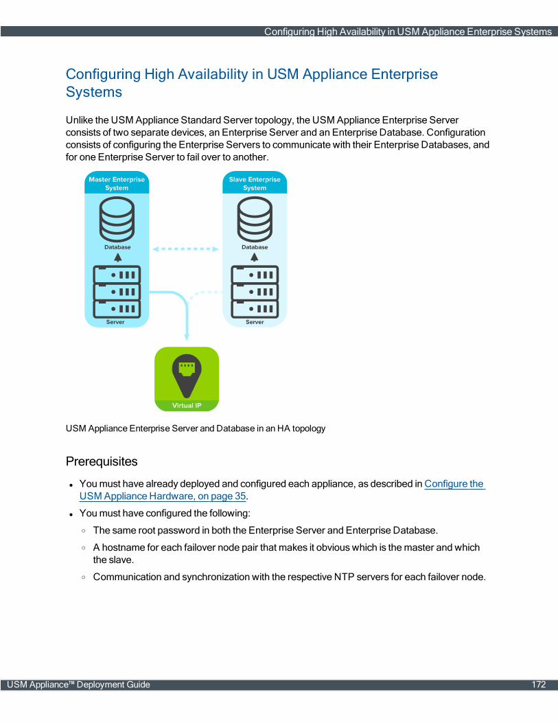
Configuring High Availability in USM Appliance EnterpriseSystems
Unlike the USM Appliance Standard Server topology, the USM Appliance Enterprise Serverconsists of two separate devices, an Enterprise Server and an Enterprise Database. Configurationconsists of configuring the Enterprise Servers to communicate with their Enterprise Databases, andfor one Enterprise Server to fail over to another.
USM Appliance Enterprise Server and Database in an HA topology
Prerequisites
l Youmust have already deployed and configured each appliance, as described in Configure theUSM Appliance Hardware, on page 35.
l Youmust have configured the following:
o The same root password in both the Enterprise Server and Enterprise Database.
o A hostname for each failover node pair that makes it obviouswhich is themaster and whichthe slave.
o Communication and synchronization with the respective NTP servers for each failover node.
Configuring High Availability in USM Appliance Enterprise Systems
USM Appliance™ Deployment Guide 172
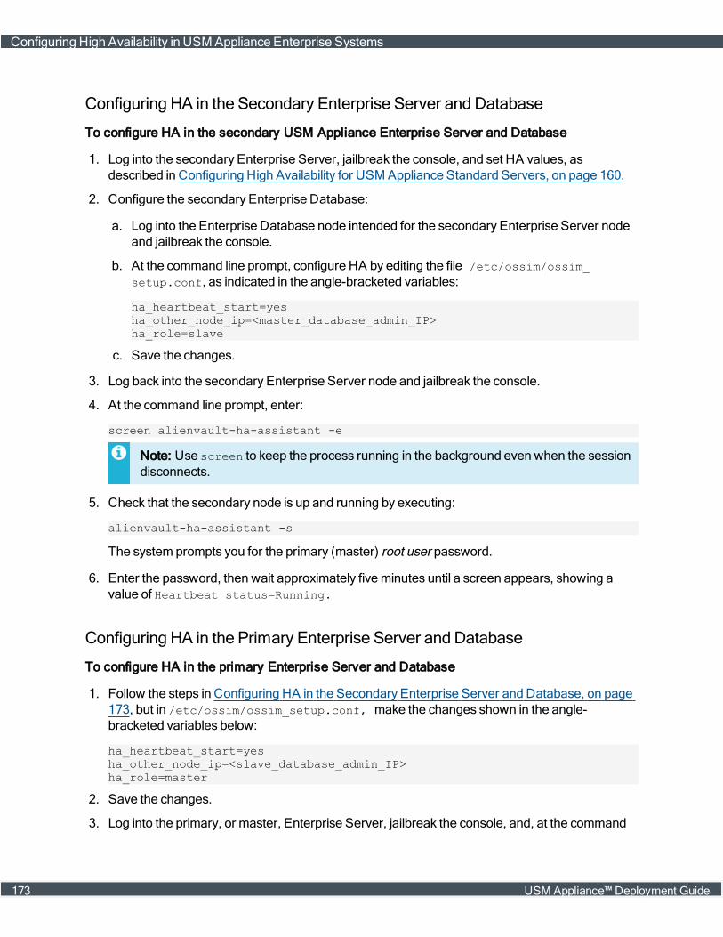
Configuring HA in the Secondary Enterprise Server and Database
To configure HA in the secondary USM Appliance Enterprise Server and Database
1. Log into the secondary Enterprise Server, jailbreak the console, and set HA values, asdescribed in Configuring High Availability for USM Appliance Standard Servers, on page 160.
2. Configure the secondary Enterprise Database:
a. Log into the Enterprise Database node intended for the secondary Enterprise Server nodeand jailbreak the console.
b. At the command line prompt, configure HA by editing the file /etc/ossim/ossim_setup.conf, as indicated in the angle-bracketed variables:
ha_heartbeat_start=yesha_other_node_ip=<master_database_admin_IP>ha_role=slave
c. Save the changes.
3. Log back into the secondary Enterprise Server node and jailbreak the console.
4. At the command line prompt, enter:
screen alienvault-ha-assistant -e
Note: Use screen to keep the process running in the background even when the sessiondisconnects.
5. Check that the secondary node is up and running by executing:
alienvault-ha-assistant -s
The system prompts you for the primary (master) root user password.
6. Enter the password, then wait approximately fiveminutes until a screen appears, showing avalue of Heartbeat status=Running.
Configuring HA in the Primary Enterprise Server and Database
To configure HA in the primary Enterprise Server and Database
1. Follow the steps in Configuring HA in the Secondary Enterprise Server and Database, on page173, but in /etc/ossim/ossim_setup.conf, make the changes shown in the angle-bracketed variables below:
ha_heartbeat_start=yesha_other_node_ip=<slave_database_admin_IP>ha_role=master
2. Save the changes.
3. Log into the primary, or master, Enterprise Server, jailbreak the console, and, at the command
Configuring High Availability in USM Appliance Enterprise Systems
173 USM Appliance™ Deployment Guide

line prompt, enter:
screen alienvault-ha-assistant -e
Note: Use screen to keep the process running in the background even when the sessiondisconnects.
Adding an Enterprise Database to an Enterprise Server
Youmust add
l The primary Enterprise Database to the secondary Enterprise Server node.
l The secondary Enterprise Database to the primary Enterprise Server node.
To add the Enterprise Database to an Enterprise Server
1. Log into the secondary Enterprise Server.
2. Select Jailbreak System, press Enter (<OK>), and Enter (<Yes>) again.
3. Add the primary Enterprise Database to the secondary Enterprise Server node, using thecommand:
alienvault-api add_system --system-ip=<master_database_admin_ip>--password=<root_password_to_master_database>
4. Log into the primary Enterprise Server node as previously described, and add the secondaryEnterprise Database:
alienvault-api add_system --system-ip=<slave_database_admin_ip>--password=<root_password_to_slave_database>
Verifying the Configuration
To check the configuration
1. Using the virtual IP address referenced in ossim-setup.conf, launch the USM Appliance webinterface in a browser.
2. Navigate to Configuration > Deployment > Components > AlienVault Center.
Both databases should be visible, including the one functioning as a secondary, or slave,database.
Configuring High Availability in USM Appliance Enterprise Systems
USM Appliance™ Deployment Guide 174
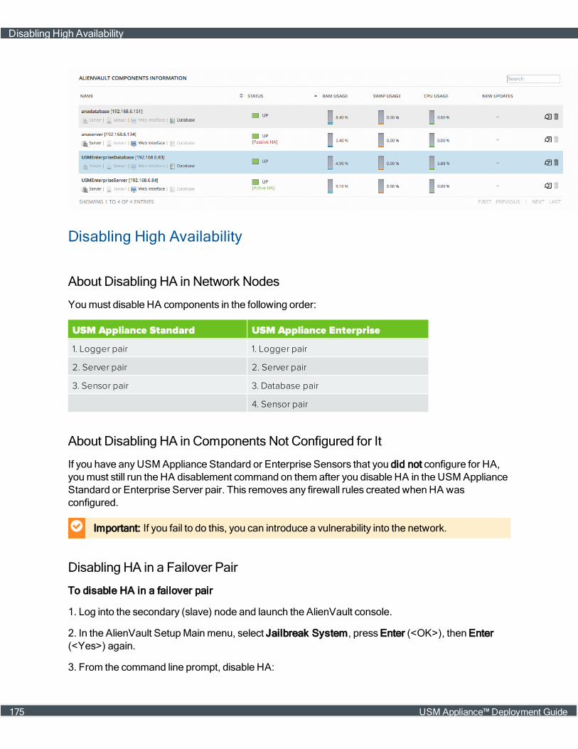
Disabling High Availability
About Disabling HA in Network Nodes
Youmust disable HA components in the following order:
USM Appliance Standard USM Appliance Enterprise
1. Logger pair 1. Logger pair
2. Server pair 2. Server pair
3. Sensor pair 3. Database pair
4. Sensor pair
About Disabling HA in Components Not Configured for It
If you have anyUSM Appliance Standard or Enterprise Sensors that you did not configure for HA,youmust still run the HA disablement command on them after you disable HA in the USM ApplianceStandard or Enterprise Server pair. This removes any firewall rules created when HA wasconfigured.
Important: If you fail to do this, you can introduce a vulnerability into the network.
Disabling HA in a Failover Pair
To disable HA in a failover pair
1. Log into the secondary (slave) node and launch the AlienVault console.
2. In the AlienVault SetupMainmenu, select Jailbreak System, press Enter (<OK>), then Enter(<Yes>) again.
3. From the command line prompt, disable HA:
Disabling High Availability
175 USM Appliance™ Deployment Guide
alienvault-ha-assistant -d
4. Exit the command linemode:
exit
5. In the primary (master) node, repeat steps 1. through 4.
6. Exit the command linemode:
exit
7. Repeat the foregoing steps for all of the component pairs in your HA deployment the previouslymentioned order.
Upgrading a USM Appliance Deployment Configured for HighAvailability
Prerequisites
To upgrade USM Appliance to a new version, youmust first temporarily disable HA. See DisablingHigh Availability , on page 175.
Order of Component Upgrade
Youmust upgrade USM Appliance Standard or Enterprise components in the following order,starting with the secondary andmoving to the primary node in each failover pair:
l Loggers
l Servers
l Sensors
Upgrading USM Appliance
To upgrade USM Appliance
1. Launch the AlienVault console on the secondary node of the component.
2. Update the node by selecting System Preferences > Update AlienVault System > UpdateSystem.
3. Press Enter (<Yes>) and wait until you see the followingmessage:
Your system has been updated successfully
4. Press Enter (<OK>).
5. Repeat steps 1. through 4. for the primary node.
Upgrading a USM Appliance Deployment Configured for High Availability
USM Appliance™ Deployment Guide 176
6. From the AlienVault SetupMainmenu, choose Jailbreak System and press Enter (<OK>).
7. Press Enter (<Yes>) to continue.
The prompt appears.
8. Re-enable HA first on the secondary node, then on the primary node:
screen alienvault-ha-assistant -e
Note: Use screen to keep the process running in the background even when the sessiondisconnects.
Upgrading a USM Appliance Deployment Configured for High Availability
177 USM Appliance™ Deployment Guide
PluginManagement
USM Appliance plugins provides logic to extract security-specific data from external applications anddevices to produce eventsmanaged by the USM Appliance system. USM Appliance comesequipped with plugins for many commonly encountered data sources that you can simply select andenable for specific assets to start collecting data and analyzing events from the applications ordevices associated with the plugins.
For a list of all the plugins that USMAppliance supports, see the USMAppliance Supported Pluginslist.
In a limited number of environments, the built-in pluginsmay not quite fit specific needs or provideenough intelligence to normalize data and extract required information from all logs or data sourcesreceived. In such cases, youmay be able to customize an existing plugin or request creation of anew plugin provided by AlienVault. You can also create your own custom plugins, choosing fromvarious options available to create plugins by scratch, and directly editing plugin configuration files,or use the plugin builder provided in the USM Appliance webUI, to create a plugin using aninteractive programwizard.
Topics covered in this section include the following:
About Plugins 179
About Plugin Updates 184
Requesting a New Plugin or Update to an Existing Plugin 186
Creating Sample Log Files and Data for Requested Plugins 187
Enabling Plugins 189
Configuring Plugins 196
Customizing and Developing New Plugins 214
USM Appliance™ Deployment Guide 178
About Plugins
USM Appliance plugins process data collected from different data sources, parse and normalize thedata, which is then saved as standard format events in the SIEM database. Users can then view andanalyze these events in the USM Appliance webUI.
Plugins define the following:
l How to collect information from an application or device.
l How to normalize the information collected from applications or devices before sending data, inthe form of standard format events, to the USM Appliance Server.
Topics included in this section include the following:
l Plugin Data Collection and Normalization
l Plugin Types
Plugin Data Collection and Normalization
A plugin is a software component that provides logic specific to extracting data collected fromexternal applications and devices. Plugins are enabled in USM Appliance Sensors which receivedata from remote hosts using the following sources or protocols:
l Syslog
l WindowsManagement Instrumentation (WMI)
l Security Device Event Exchange (SDEE)
l Database
l Other protocols
Any system that processes logs requires a parser to read them, and to extract and convert their datainto standard event fields. The following illustration shows the way in which a USM ApplianceSensor collects syslog events from different devices, where enabled plugins can then process andnormalize the event data contained in specific syslog files.
About Plugins
179 USM Appliance™ Deployment Guide

USM Appliance Sensor diagram
During data normalization, a plugin evaluates information from each line of a log file and translates itto an event that identifies the event's type and subtype within the USM Appliance taxonomy. (SeeUSM Appliance Event Taxonomy.) Normalization also converts portions of each log file line intocommon data fields such as user, date and time, and source or destination IP address.
Log normalization process
About Plugins
USM Appliance™ Deployment Guide 180

Normalizing information into standard event data fields lets USM Appliance display informationuniformly and also correlate events from various individual systems to generate alarms.
Plugin Types
USM Appliance supports two basic types of plugins:
l Detector Plugins — Type of plugins that receive and extract events primarily from log files. Ali-enVault provides a wide range of detector plugins for most vendor security applications anddevices youmay have deployed in your environment.
l Monitor Plugins — Type of plugins that collect information primarily by executing commands,such as nmap and tcptrack, that query or retrieve information and status from selected targetsthey aremonitoring.
Note: For a current list of all AlienVault provided plugins, see the data sheet.
Detector Plugins
This is a group of plugins that receive and extract events from logs.
Using syslog or some other type of remote collection protocol such as SDEE, detector pluginsprocess the following data:
l Text logs created by the rsyslog collection system. USM Appliance uses rsyslog as itsdefault syslog implementation; the log configuration files of all external devices reside in/etc/rsyslog.d.
l Logs from remote systems.
The Source field of each plugin file indicates the type of detector plugin.
About Plugins
181 USM Appliance™ Deployment Guide

PluginSource Description Examples
Database Monitors the content of external databases. Database plugins extractdata from an external database and turn them into USM Applianceevents. Supported databases are MySQL and Microsoft SQL Server.The database plugin configuration file provides information on howUSM Appliance should connect to and query the database. SeeConfiguring Database Plugins to see an example database pluginconfiguration file and to obtain more information on configuringdatabase plugins.
mcafee-epo
Log Monitors a log file, usually receiving data through syslog. Logplugins extract events from log files by matching each line in a log fileusing a regular expression. The plugin then normalizes theinformation in the text to create events containing event field datafrom the text. See Configuring Log Plugins to see an example logplugin configuration file and to obtain more information onconfiguring log plugins.
cisco-asa
Security DeviceEvent Exchange(SDEE)
Monitors Cisco devices, using SDEE protocol. Cisco Systems IPSSensor 5.0 uses the Security Device Event Exchange (SDEE) protocolto specify the format of messages used to communicate eventsgenerated by certain Cisco security devices. See Configuring SDEEPlugins to see an example SDEE plugin configuration file and toobtain more information on configuring SDEE plugins.
cisco-ips
WindowsManagementInstrumentation(WMI)
Remotely connects to Microsoft Windows events and data without anagent. Windows Management Instrumentation (WMI) plugins collectMicrosoft Windows events and data remotely. These plugins collectthe information, without an agent, using the Windows ManagementInstrumentation Command Line (WMIC). See ConfiguringWMI Pluginsto see an example WMI plugin configuration file and to obtain moreinformation on configuring WMI plugins.
wmi-application-logger
Detector plugin types
Most detector plugins work automatically, without additional configuration, after you enable them.(See Enabling Plugins.)
IDM Plugins
IDMPlugins are a special type of detector plugin that collect additional information about devicesand applications. This information is used to enhance themetadata of individual events whenUSM Appliance processes event data collected from other plugins. IDM plugins include thefollowing:
l AlienVault_HIDS-IDM
l arpalert-idm
l cisco-acs-idm
l linuxdhcp-idm
About Plugins
USM Appliance™ Deployment Guide 182
l nmap-hosts
l snare-idm
l prads
Note: The prads IDM plugin, which identifies and collects information on network servicesrunning on hosts, is automatically enabled at startup, by default. Thus, no additional setupor configuration is required before you can start taking advantage of IDM information.Although not required, you can enable additional IDM plugins to gather information fromdifferent sources. For more information, see Enabling Plugins.
Scheduled inventory tasks such as asset discovery scans,WMI scans, and availabilitymonitoringcan also collect IDM information. Information collected by the IDM plugins and other scheduledprocesses is stored in an internal database, which alsomaintains historical data retrieved for thesame hosts.
USM Appliance queries this data to enrich themetadata for events that are processed from otherdevice and application-specific plugins. In addition, if values have changed in the historical datamaintained for IDM data sources, the USM Appliance will generate an anomaly event that showsthe change between the new and previous values. For more information on viewing anomalyevents containing IDM information, see Reviewing Security Events.
IDM information collected by host, based on their IP address, includes the following:
l UUID, IP address, and domain of the host
l ID of the IDM source that generated the event (such as nmap, ocs, nagios)
l Hostname associated with the IP address
l MAC address
l Operating system
l CPU description and frequency
l RAM (inmegabytes) on the host
l Host graphics cards
l List of users that have logged on or off
l List of active services
l List of software and hardware installed
l State of device or asset (on or off, up or down)
Monitor Plugins
While detector plugins generate events using information from log files, databases, or queries ofother systems, monitor plugins execute commands in USM Appliance to check the status of thetargets theymonitor. Monitor plugins also help correlate log events in alarms bymatching eventsagainst the current status of USM Appliance.
About Plugins
183 USM Appliance™ Deployment Guide
Monitor plugins aremeant to be used from directives to request information from systems. Theyreturn the status when the target theymonitor makes a request. Examples include plugins forprograms such as nmap, ping, whois, and tcptrack.
Most monitor plugins work automatically, without additional configuration, after you enable them.(See Enabling Plugins.)
Note: Monitor pluginsmust be enabled before you can use them from directives. Forinformation about directives, see About Correlation Directives.
About Plugin Updates
AlienVault USM Appliance sends users a notification when there is an update to the plugin feed,accessible from the USM ApplianceMessage Center. Updates can consist of either an update to anexisting plugin or a new plugin.
These updates typically occur on a biweekly basis. Starting with release version 5.4, plugin updatescan also be scheduled and you can configure threat intelligence and plugin updates to runautomatically. See Updating USM ApplianceOnline.
Note: The USM Appliance Sensor and USM Appliance Server must be updatedindependently.
Verifying If There Is a NewPlugin Update
To verify whether you need to update the plugin feed
l Open the USM ApplianceMessage Center by clicking the envelope icon ( ).
If you see amessage similar to "Plugins Feed Update - 2016-10-01," it means that you have aplugin feed update. The Plugins Feed Update displays the release notes, as shown.
About Plugin Updates
USM Appliance™ Deployment Guide 184
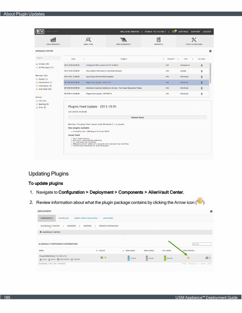
Updating Plugins
To update plugins
1. Navigate to Configuration > Deployment > Components > AlienVault Center.
2. Review information about what the plugin package contains by clicking the Arrow icon ( )
About Plugin Updates
185 USM Appliance™ Deployment Guide
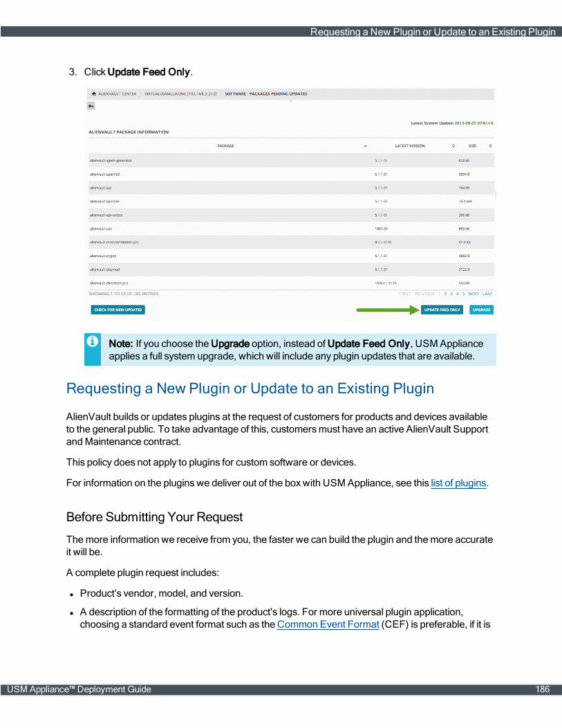
3. Click Update Feed Only.
Note: If you choose the Upgrade option, instead of Update Feed Only, USM Applianceapplies a full system upgrade, which will include any plugin updates that are available.
Requesting a New Plugin or Update to an Existing Plugin
AlienVault builds or updates plugins at the request of customers for products and devices availableto the general public. To take advantage of this, customersmust have an active AlienVault SupportandMaintenance contract.
This policy does not apply to plugins for custom software or devices.
For information on the plugins we deliver out of the boxwith USMAppliance, see this list of plugins.
Before Submitting Your Request
Themore information we receive from you, the faster we can build the plugin and themore accurateit will be.
A complete plugin request includes:
l Product’s vendor, model, and version.
l A description of the formatting of the product's logs. For more universal plugin application,choosing a standard event format such as the Common Event Format (CEF) is preferable, if it is
Requesting a New Plugin or Update to an Existing Plugin
USM Appliance™ Deployment Guide 186
available and suitable to your needs.
Youmay also want to consider using the product's default log settings in defining which fields tolog. However, if a product has a particular logging configuration that you want the plugin tosupport, you should include that in your request.
l A description of how you use the product, including which events and which data inside thoseevents provide themost relevance to your business.
l Specific log samples or database dumps of relevant device events. For best results, exclude anyextraneous noise from the log samples, while still retaining all the data needed to differentiate thevarious events you want to capture with a plugin.
Note: For tips and best practice guidelines on creating the sample logs and databasedumps to submit with a plugin request, see "Creating Sample Log Files and Data forRequested Plugins."
l If you need information other than the date, source, destination, username, and protocol extrac-ted from the logs, specify this in your request, and provide an example. This helps us test the plu-gin tomake sure it can successfully extract that data.
l Use case for the new plugin and the business value of the application or device to your organ-ization. This information helps us assign a priority to your request.
After you have collected the information, click here to submit your request.
Creating Sample Log Files and Data for Requested Plugins
As part of submitting a request for a new AlienVault USM Appliance plugin, you also need to includea log sample or database dump that includes all the relevant events and data patterns you want theplugin to be able to process and analyze for events. Before sending the sample file as part of yourrequest, youmay also want to examine the sample file, remove any extraneous entries of datapatterns you don't need to capture, while ensuring the sample file contains asmany of the datapatterns you do want the plugin to process.
Creating Sample Files for Asset Log-based Plugins
Besides a direct examination and cleanup of log files generated by an asset, AlienVault alsorecommends a process in which you forward the asset’s syslog files directly to the USM ApplianceSensor. Then, over the span of a few days, try to invoke asmany event types as possible, so thatrelevant data will be captured as syslog entries in the/var/log/alienvault/devices/<IPaddress> folder saved on the USM Appliance Sensor.
Note: Plugin syslog files for each asset are saved on the USM Appliance Sensor in individual/var/log/alienvault/devices/<IPaddress> folders, one folder per asset IP address.
Creating Sample Log Files and Data for Requested Plugins
187 USM Appliance™ Deployment Guide

Following this data collection period, you can pull this log file from the sensor and deliver it along withyour plugin request, so the AlienVault Plugin Teamwill have a good sampling of data patterns todevelop a new plugin.
Creating Sample Log Files for Windows-Based Applications
Creating a plugin sample log file for Windows applications that only log events to theWindowsEventViewer requires a different approach. In this case, one effective way to create a useful sample logfile, to submit with a new plugin request, is to deploy an AlienVault HIDS Agent on the relevantWindows host. You can then configure the agent’s ossec.conf file to capture the appropriateevents from theWindows host.
Note: For details on deploying a HIDS Agent, see Deploy AlienVault HIDS Agents. For detailson configuring the HIDS Agent for event logging, see Tutorial: Reading a Log File with anHIDS Agent onWindows.
To configure the logging of events by the HIDS agent, you can perform Tasks 1 and 2 of the tutorialon reading log files with a HIDS agent. Task 1 specifies the source location of data generated by theWindows application. Task 2 in the tutorial sets the scope of events logged to LOGALL (based on thescope of events defined in the ossec.conf configuration file).
After allowing some time for the HIDS agent to collect log entries, you can check the/var/ossec/archives/archives.log file on USM Appliance for the specific events from theWindows application. To create the sample log file to submit with your plugin request, you can usecommands such as cat and grep (Task 3) to trim down the archives.log file to contain only loglines for the specific events you want a new plugin to catch.
Note: As an alternatemethod to using the HIDS agent to collect log entries for Windows-based hosts and applications, you can also use the NXLog plugin, provided withUSM Appliance. Using thismethod, you can update the nxlog.conf file to define theWindows event data you want to collect for a specific device. You can then submit, with yournew plugin request, the log file data collected by the NXLog plugin (located in the/var/log/alienvault/devices/<IPaddress> folder on the USM Appliance Sensor. Formore information, seeMicrosoft WindowsEvent Logs through NXLog.
Creating Sample Data for Events Stored in a Database
Creating a plugin for events stored in a database generally requires two things. First youmust definethe query needed to extract information you want to view in events, mapping database information tothe standardized USMAppliance event fields. (Youmay also want to provide some sort of mappingof the database schemawith the definition of columns in tables that you want to include in capturedevent data.) Second, you will need to provide some sort of export or dump of a subset of the datastored in the database to test the plugin.
Creating Sample Log Files and Data for Requested Plugins
USM Appliance™ Deployment Guide 188

Note: Themethods of exporting data or creating data dumps and database queries will varybased on the specific database engine used, for example, Oracle or SQL Server. Consult yourvendor’s documentation for specific information on performing the tasksmentioned.
Enabling Plugins
AlienVault providesmore than one way to enable plugins in USM Appliance. First, you can enableplugins on specific discovered assets, or you can enable plugins globally on USMApplianceSensors. In addition, based on the specific plugin, you can enable plugins using different tools,including the USMAppliance webUI, the Getting StartedWizard, or the AlienVault console. Thefollowing topics providemore information about the two choices available for enabling a specificplugin:
l Enabling Plugins on Assets
l Enabling Plugins from the USM Appliance Sensor Configuration
Important: Be careful not to enable the same plugin twice, because this will generate duplicateevents.
For those plugins that allow it, enabling plugins on specific assets is generally recommended overenabling plugins on the USM Appliance Sensor. Plugins enabled at the asset level are automaticallyconfigured, whereas plugins enabled at the sensor level must often be configured first. For log-based plugins, thismeans setting up rsyslog collection and processing, and log rotation. (SeeConfigure the USM Appliance Sensor to Receive Logs Through Syslog.)
Convenience and performancemay also be factors in choosing whether to enable plugins onindividual assets, or to enable them on the USM Appliance Sensor. Enabling plugins on individualassets can help distribute the load of handling heavy traffic by running copies of the plugin onmultiple processors or cores, rather than on a single one. However, if you want to use the sameplugin with a large number of assets, and volume of traffic is not an issue, youmay find it easier toenable and configure the plugin on the sensor.
Enabling Plugins on Assets
After you run a scan of your network to discover assets, the discovered assets are saved in theUSM Appliance database. (For information on scanning to add assets, see Adding Assets byScanning for New Assets.) You can then select and enable plugins on individual discovered assets.You can enable up to 10 plugins per discovered asset.
Enabling Plugins From Asset Details in the Web UI
You can enable all plugins, except for database andmonitor plugins, from the USMAppliance webUI.
Enabling Plugins
189 USM Appliance™ Deployment Guide

Note: To enable database andmonitor plugins, see Enabling Plugins from the USM ApplianceSensor Configuration.
To enable a plugin from the Asset Details display
1. Navigate to Environment > Assets & Groups > Assets.
2. Select the asset for which you want to enable plugins.
3. Click themagnifying glass icon ( ).
4. Click the Plugins tab.
5. Click Edit Plugins.
6. Select a vendor, a model, and a version of the plugin you want to enable.
7. Click Add Plugin.
8. If you want to add another plugin, select another plugin in the sameway as before and click AddPlugin; otherwise, click Save.
Enabling Plugins
USM Appliance™ Deployment Guide 190
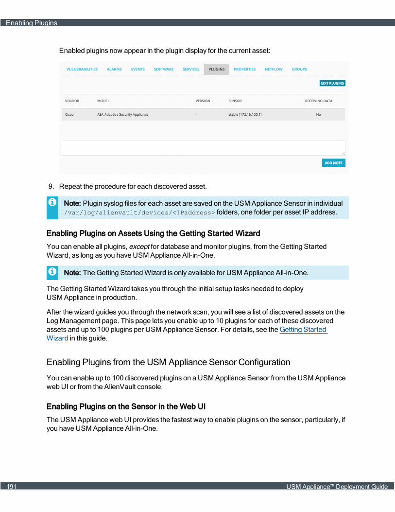
Enabled plugins now appear in the plugin display for the current asset:
9. Repeat the procedure for each discovered asset.
Note: Plugin syslog files for each asset are saved on the USM Appliance Sensor in individual/var/log/alienvault/devices/<IPaddress> folders, one folder per asset IP address.
Enabling Plugins on Assets Using the Getting Started Wizard
You can enable all plugins, except for database andmonitor plugins, from theGetting StartedWizard, as long as you have USM Appliance All-in-One.
Note: TheGetting StartedWizard is only available for USM Appliance All-in-One.
TheGetting StartedWizard takes you through the initial setup tasks needed to deployUSM Appliance in production.
After the wizard guides you through the network scan, you will see a list of discovered assets on theLogManagement page. This page lets you enable up to 10 plugins for each of these discoveredassets and up to 100 plugins per USM Appliance Sensor. For details, see theGetting StartedWizard in this guide.
Enabling Plugins from the USM Appliance Sensor Configuration
You can enable up to 100 discovered plugins on a USMAppliance Sensor from the USMAppliancewebUI or from the AlienVault console.
Enabling Plugins on the Sensor in the Web UI
TheUSMAppliance webUI provides the fastest way to enable plugins on the sensor, particularly, ifyou have USM Appliance All-in-One.
Enabling Plugins
191 USM Appliance™ Deployment Guide

To enable a plugin on the sensor configuration page in the USM Appliance web UI
1. In the USM Appliance webUI, navigate to Configuration > Deployment > Components> AlienVault Center.
2. Click one of the USM Appliance Sensors.
3. Click Sensor Configuration > Collection.
The left column of the Sensor Configuration page shows the enabled plugins. The right columnshows the plugins available for enablement.
4. Move a plugin from one side to the other in either of these ways:
l Drag a plugin from one column to the other.
l Use the links [+] or [-] next to a specific item.
5. Click Apply Changes.
6. Configure rsyslog and logrotate. For instructions, see Configure the USM Appliance Sensorto Receive Logs Through Syslog.
Enabling Plugins from the AlienVault Console
You can enable all plugins on the sensor from the AlienVault console. However, youmay find it'sfaster to enable plugins through the USMAppliance webUI, if you have USM Appliance All-in-One.
To enable plugins from the AlienVault console
1. Connect to the AlienVault Console through SSH and use your credentials to log in.
The AlienVault Setupmenu displays.
2. Select Configure Sensor.
Enabling Plugins
USM Appliance™ Deployment Guide 192
3. Select Configure Data Source Plugins.
4. Use the keyboard arrow keys tomove to the plugin, select the plugin by pressing the spacebar,and then press Enter (<OK>).
5. Press <Back> until you are on the AlienVault Setupmenu again; select Apply all Changes.
6. Press <Yes> to confirm.
USMAppliance applies the changes and restarts all the services, whichmay take severalminutes.
7. Configure rsyslog and logrotate. For instructions, see Configure the USM Appliance Sensorto Receive Logs Through Syslog.
Enabling Monitor Plugins
Monitor plugins check status and request information from the systems they are configured tomonitor. Monitor plugins generate text logs that are fed into the syslog, like normal logs. The logentries can be used to correlate log events in alarms bymatching those events against the currentstatus of systems.
To enable a monitor plugin
1. Connect to the AlienVault Console through SSH and use your credentials to log in.
The AlienVault Setupmenu displays.
2. Select Configure Sensor.
3. Select Configure Monitor Plugins.
4. Use the keyboard arrow keys tomove to the plugin, select the plugin by pressing the spacebar,and then press Enter (<OK>).
5. Press <Back> until you are on the AlienVault Setupmenu again; select Apply all Changes.
6. Press <Yes> to confirm.
USMAppliance applies the changes and restarts all the services, whichmay take severalminutes.
Note: If you want to confirm that the correct plugin has been enabled, jailbreak the system andopen /etc/ossim/agent/config.cfg. The new plugin will appear inside the [plugins]section.
Confirming that an Enabled Plugin IsWorking Properly
It's good practice to test whether or not a plugin is working correctly, after it's been enabled.
Enabling Plugins
193 USM Appliance™ Deployment Guide
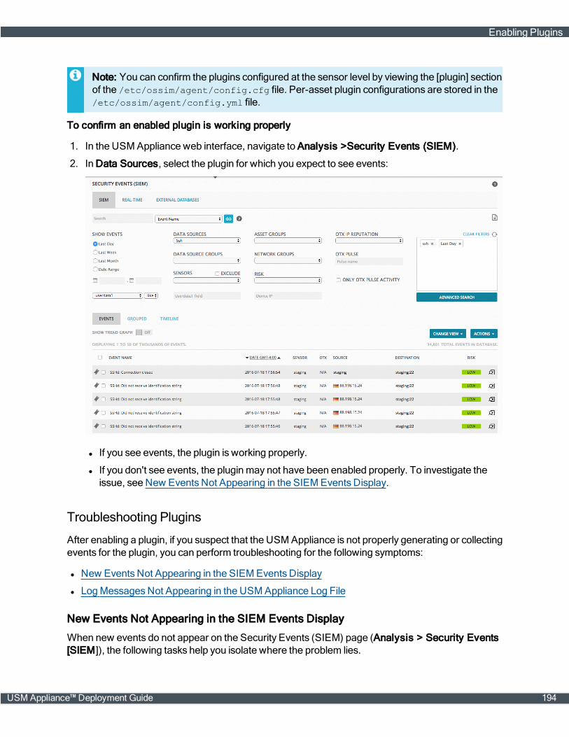
Note: You can confirm the plugins configured at the sensor level by viewing the [plugin] sectionof the /etc/ossim/agent/config.cfg file. Per-asset plugin configurations are stored in the/etc/ossim/agent/config.yml file.
To confirm an enabled plugin is working properly
1. In the USM Appliance web interface, navigate to Analysis >Security Events (SIEM).
2. In Data Sources, select the plugin for which you expect to see events:
l If you see events, the plugin is working properly.
l If you don't see events, the pluginmay not have been enabled properly. To investigate theissue, see New Events Not Appearing in the SIEMEvents Display.
Troubleshooting Plugins
After enabling a plugin, if you suspect that the USMAppliance is not properly generating or collectingevents for the plugin, you can perform troubleshooting for the following symptoms:
l New Events Not Appearing in the SIEMEvents Display
l LogMessagesNot Appearing in the USM Appliance Log File
New Events Not Appearing in the SIEM Events Display
When new events do not appear on the Security Events (SIEM) page (Analysis > Security Events[SIEM]), the following tasks help you isolate where the problem lies.
Enabling Plugins
USM Appliance™ Deployment Guide 194

To confirm receipt of syslog data from remote devices
1. Validate that you are receiving syslog packets from the source device by taking either of the fol-lowing steps:
l Open the AlienVault console on the USM Appliance Sensor appliance and log in, using SSH.
Or
l Log in as root, using an SSH shell.
2. (AlienVault console only) From the AlienVault Mainmenu, select the Jailbreak System optionto gain command line access.
3. Validate that you are receiving syslog packets from the source device:
tcpdump –i eth0 –v –w /dev/null src <device_IP_Address> and port 514
If no packets appear in output, then USM Appliance is not receiving data from the plugin.
If the output shows the captured packets, it indicates that the issue is not the connection. Youmust now verify whether the AlienVault Agent Service is operating correctly.
4. Exit this tool by pressing Ctrl+C .
5. Restart the Syslog Collector and the AlienVault Agent Service:
/etc/init.d/rsyslog restart/etc/init.d/ossim-agent restart
6. Search within the output for any plugin errors in the Agent Logs:
cat /var/log/alienvault/agent* | grep Plugin[<enabled_plugin_id>]
Errors would look similar to the following examples:
Plugin[1683] Total lines [116] TotalEvents:[58] EPS: [0.00] elapsed[10.00] secondsPlugin[4005] Total lines [4] TotalEvents:[0] EPS: [0.00] elapsed [10.01]seconds
7. To exit the command line, enter exit and press Enter.
Log Messages Not Appearing in the USM Appliance Log File
If you know that logmessages are reaching the intended USM Appliance component, but they don'tshow up in the USM Appliance log file, check the syslog configuration.
To check the syslog configuration
1. Connect to the AlienVault console via SSH and log in.
2. From the AlienVault Mainmenu, select Jailbreak System option to gain command line access.
3. Verify whether the USM Appliance Sensor was configured to accept syslog transmissions. SeeConfiguring Log Plugins.
Enabling Plugins
195 USM Appliance™ Deployment Guide

Messages from your device appear in the corresponding syslog file differently depending onwhether or not syslog was configured.
l If there is no syslog configuration, enter:
tail -f /var/log/syslog
l If there is a syslog configuration, enter:tail -f /path/to/<dataSource_location>.log
l If the plugin has been enabled on a per-asset basis:
tail -f /var/log/alienvault/devices/<asset_IP_address>/<asset_IP_address>.log
4. Verify whether messages from your device appear in the corresponding syslog file.
These files contain themessages from rsyslog. By reviewing these files, you can see whetherthemessages are arriving or not.
l If you determine that themessages are arriving, but you see no events, the error is in eitherthe plugin or the agent configuration.
l If themessages are not arriving, verify that the syslog port (514) is receivingmessages. Seestep 3 under New Events Not Appearing in the SIEMEvents Display.
Configuring Plugins
This section describes the basic configuration of different plugin types. Topics include the following:
l Configuring Log Plugins
l Configuring Database Plugins
l ConfiguringWMI Plugins
l Configuring SDEE Plugins
l ConfiguringMonitor Plugins
Configuring Log Plugins
Log plugins extract events from log files bymatching each line in a log file using a regular expression.The plugin then normalizes the information to create events containing the data fields from the text.
Sample Log Plugin File
# Alienvault plugin# Author: Alienvault Team at [email protected]# Plugin ssh id:4003 version: 0.0.2# Last modification: 2015-05-13 16:11## Plugin Selection Info:# OpenBSD:OpenSSH:-## END-HEADER
Configuring Plugins
USM Appliance™ Deployment Guide 196

# Accepted products:# openbsd - openssh 5.4# openbsd - openssh 5.5# openbsd - openssh 5.6# openbsd - openssh 5.7# openbsd - openssh 5.8# openbsd - openssh 5.8p2# openbsd - openssh 5.9# Description:###
[DEFAULT]plugin_id=4003dst_ip=\_CFG(plugin-defaults,sensor)dst_port=22
[config]type=detectorenable=truesource=loglocation=/var/log/auth.logcreate_file=trueprocess=sshdstart=nostop=nostartup=/etc/init.d/ssh startshutdown=/etc/init.d/ssh stop
[translation]none=1opened=25publickey=2version=22throughput=23closed=26password=1
[0000 - Failed password]event_type=eventregexp=(?P<date>\w{3}\s+\d{1,2}\s\d\d:\d\d:\d\d)\s+(?P<dst>\S+) sshd\[\d+\]:Failed password for\s(?P<info>invalid user\s)?(?P<user>\S+)\sfrom\s(?P<src>\S+)\sport\s(?P<sport>\d{1,5})date={normalize_date($date)}plugin_sid=1src_ip={resolv($src)}dst_ip={resolv($dst)}src_port={$sport}username={$user}userdata1={$info}userdata2={$dst}device={resolv($dst)}
[0001 - Invalid user]event_type=event
Configuring Plugins
197 USM Appliance™ Deployment Guide

regexp=(?P<date>\w{3}\s+\d{1,2}\s\d\d:\d\d:\d\d)\s(?P<dst>\S+)\ssshd\[\d+\]:Invalid user (?P<user>\S+) from\s+(?P<src>\S+)date={normalize_date($date)}plugin_sid=3src_ip={resolv($src)}dst_ip={resolv($dst)}username={$user}device={resolv($dst)}...<Additional rule matching Regex expressions added, as needed>
About Extracting Events From Logs with Regular Expressions
Log plugins extract events from logs bymatching each line in the log according to a regularexpression. The plugin then normalizes the data fields from the text. For example, when a logmessage arrives, as shown:
Feb 8 10:09:06 server1 sshd[24472]: Failed password for dgil from 192.168.6.69port 33992 ssh2
the pluginmatches it with a regular expression (regex) in the rule of an SSH plugin:
[0000 - Failed password]
As soon as a rulematches a log line, matching stops, nomatter how many remaining rulesmaymatch. The regular expression also extracts the relevant information from thematched log line.Theregex fields, shown in boldface in the following example, identify the text to bemapped to theSecurity Event fields:
regexp=(?P<date>\w{3}\s+\d{1,2}\s\d\d:\d\d:\d\d)\s+(?P<dst>\S+) sshd\[\d+\]:Failed password for\s(?P<info>invalid user\s)?(?P<user>\S+)\sfrom\s(?P<src>\S+)\sport\s(?P<sport>\d{1,5})
As a second step, the plugin normalizes that information for presentation within the USM ApplianceSecurity Event fields:
Date = Feb 8 10:09:06src_ip =192.168.6.69Username = dgil
The data source log format dictates the level of detail needed to generate events. The data sourcecould require either just a few rules or one particular rule for each event.
The field plugin_sid identifies each individual event. This field is assigned either to every rule or itcan be based on a field captured from a log line.
[0000 - Failed password]event_type=eventregexp=(?P<date>\w{3}\s+\d{1,2}\s\d\d:\d\d:\d\d)\s+(?P<dst>\S+) sshd\[\d+\]:Failed password for\s(?P<info>invalid user\s)?(?P<user>\S+)\sfrom\s(?P<src>\S+)\sport\s(?P<sport>\d{1,5})date={normalize_date($date)}plugin_sid=1
Configuring Plugins
USM Appliance™ Deployment Guide 198
src_ip={resolv($src)}dst_ip={resolv($dst)}src_port={$sport}username={$user}userdata1={$info}userdata2={$dst}device={resolv($dst)}
Configure the USM Appliance Sensor to Receive Logs Through Syslog
Important: This task is only required if you enable the Log plugin through Enabling Pluginsfrom the USM Appliance Sensor Configuration. AlienVault strongly recommends that youenable Log plugins through assets for its ease of use andmaintenance.
For text logs received via the rsyslog service running on USMAppliance, you need to define thesyslog routing rules in the rsyslog configuration file, located in /etc/rsyslog.d/. You also needto add a configuration file for logrotate, located in /etc/logrotate.d/, to rotate the logs.
To add rules for rsyslog and logrotate
1. Connect to the AlienVault Console through SSH and use your credentials to log in.
The AlienVault Setupmenu displays.
2. On the AlienVault Setupmainmenu, select Jailbreak System to gain command line access.
Select Yes when prompted. You will be in the root directory.
3. Create a new configuration file to filter incoming logs:
nano –w /etc/rsyslog.d/<dataSource_name>.conf
Where:
<dataSource_name> = the plugin name
4. Add the following line to the configuration file to identify the device fromwhich you shouldreceive logs:
if ($fromhost-ip == ‘<IP_Address>’) then <path>/<dataSource_name>.log& ~
Where:
<dataSource_name> = the plugin name
<IP_Address> = the IP address of the device
<path> = path to the file listed in the location field of the Log pluginconfiguration file
5. Save the file by pressing Crtl+W and exit the editor by pressing Crtl+X.
6. Restart the Syslog Collector:
Configuring Plugins
199 USM Appliance™ Deployment Guide
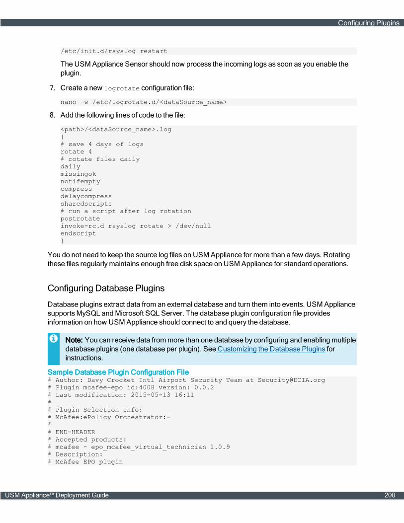
/etc/init.d/rsyslog restart
TheUSM Appliance Sensor should now process the incoming logs as soon as you enable theplugin.
7. Create a new logrotate configuration file:
nano –w /etc/logrotate.d/<dataSource_name>
8. Add the following lines of code to the file:
<path>/<dataSource_name>.log{# save 4 days of logsrotate 4# rotate files dailydailymissingoknotifemptycompressdelaycompresssharedscripts# run a script after log rotationpostrotateinvoke-rc.d rsyslog rotate > /dev/nullendscript}
You do not need to keep the source log files on USM Appliance for more than a few days. Rotatingthese files regularlymaintains enough free disk space on USM Appliance for standard operations.
Configuring Database Plugins
Database plugins extract data from an external database and turn them into events. USM AppliancesupportsMySQL andMicrosoft SQL Server. The database plugin configuration file providesinformation on how USM Appliance should connect to and query the database.
Note: You can receive data frommore than one database by configuring and enablingmultipledatabase plugins (one database per plugin). See Customizing the Database Plugins forinstructions.
Sample Database Plugin Configuration File# Author: Davy Crocket Intl Airport Security Team at [email protected]# Plugin mcafee-epo id:4008 version: 0.0.2# Last modification: 2015-05-13 16:11## Plugin Selection Info:# McAfee:ePolicy Orchestrator:-## END-HEADER# Accepted products:# mcafee - epo_mcafee_virtual_technician 1.0.9# Description:# McAfee EPO plugin
Configuring Plugins
USM Appliance™ Deployment Guide 200
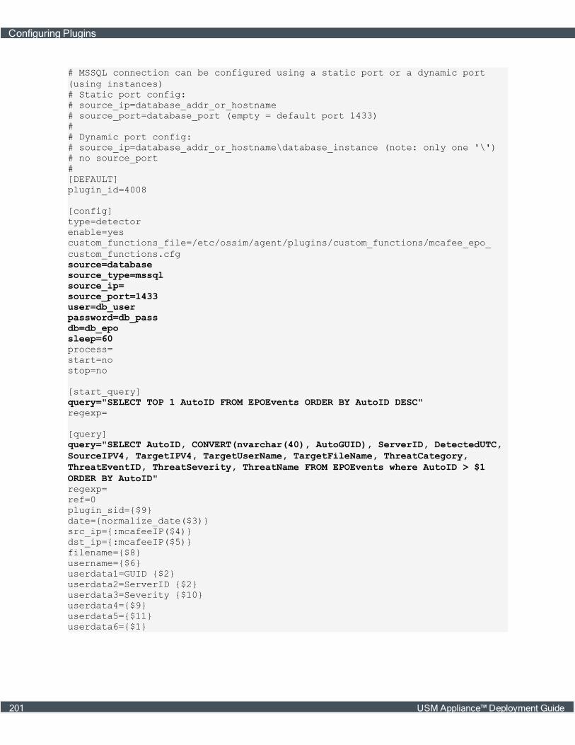
# MSSQL connection can be configured using a static port or a dynamic port(using instances)# Static port config:# source_ip=database_addr_or_hostname# source_port=database_port (empty = default port 1433)## Dynamic port config:# source_ip=database_addr_or_hostname\database_instance (note: only one '\')# no source_port#[DEFAULT]plugin_id=4008
[config]type=detectorenable=yescustom_functions_file=/etc/ossim/agent/plugins/custom_functions/mcafee_epo_custom_functions.cfgsource=databasesource_type=mssqlsource_ip=source_port=1433user=db_userpassword=db_passdb=db_eposleep=60process=start=nostop=no
[start_query]query="SELECT TOP 1 AutoID FROM EPOEvents ORDER BY AutoID DESC"regexp=
[query]query="SELECT AutoID, CONVERT(nvarchar(40), AutoGUID), ServerID, DetectedUTC,SourceIPV4, TargetIPV4, TargetUserName, TargetFileName, ThreatCategory,ThreatEventID, ThreatSeverity, ThreatName FROM EPOEvents where AutoID > $1ORDER BY AutoID"regexp=ref=0plugin_sid={$9}date={normalize_date($3)}src_ip={:mcafeeIP($4)}dst_ip={:mcafeeIP($5)}filename={$8}username={$6}userdata1=GUID {$2}userdata2=ServerID {$2}userdata3=Severity {$10}userdata4={$9}userdata5={$11}userdata6={$1}
Configuring Plugins
201 USM Appliance™ Deployment Guide

Understanding the Plugin Configuration File
See below for a description of various sections in the sample plugin configuration file above.
The Config Section
In the database plugin configuration file example, the section that starts with [config] tellsUSM Appliance how to connect to the database. This consists of the following parameters.
[config]type=detectorsource=databasesource_type=<database_type>source_ip=<database_IP>source_port=<database_port>user=<username>password=<user_password>db=<database_name>
The Start_Query Section
To find the point where the database plugin should begin capturing data, USMAppliance uses aquery called start_query. This query obtains the last row in a table identified by a sequence number.The following code example initiates a query for theMicrosoft SQL Server database.
[start_query]query="SELECT TOP 1 AutoID FROM EPOEvents ORDER BY AutoID DESC"
The Query Section
USM Appliance queries the database as soon as a database plugin is loaded and, thereafter, everyfew seconds.
The duration between queries depends on the value of sleep in each plugin's configuration file.Default values range from 2 to 60 seconds and are configurable. For information about customizingexisting or developing new plugins, see Customizing and Developing New Plugins and its relatedtopics.
This query starts with [query] and also references the [start_query] code line, shown in boldbelow.
[query]query="SELECT AutoID, CONVERT(nvarchar(40), AutoGUID), ServerID, DetectedUTC,SourceIPV4, TargetIPV4, TargetUserName, TargetFileName, ThreatCategory,ThreatEventID, ThreatSeverity, ThreatName FROM EPOEvents where AutoID > $1ORDER BY AutoID"regexp=
Important: Youmust leave the regexp field empty (shown below the query), becausedatabase plugins use it in operation.
Fields containing $ correspond to fields in the database query. For example:
Configuring Plugins
USM Appliance™ Deployment Guide 202
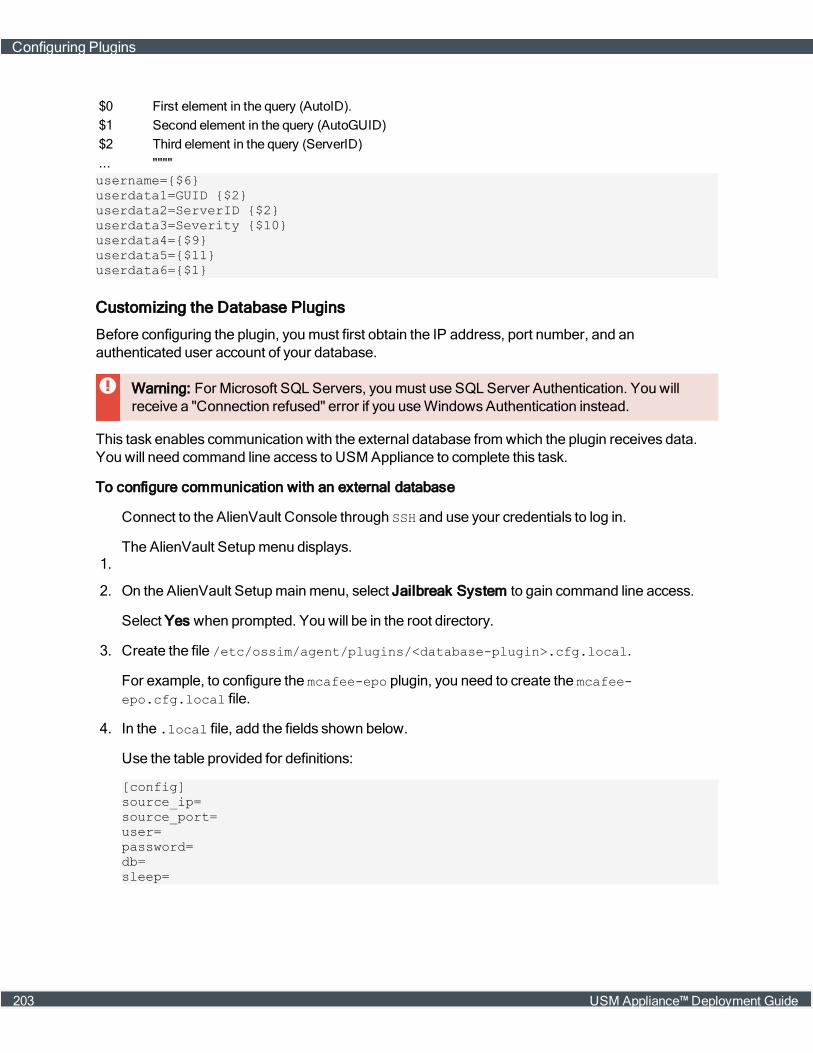
$0 First element in the query (AutoID).$1 Second element in the query (AutoGUID)$2 Third element in the query (ServerID)... """"username={$6}userdata1=GUID {$2}userdata2=ServerID {$2}userdata3=Severity {$10}userdata4={$9}userdata5={$11}userdata6={$1}
Customizing the Database Plugins
Before configuring the plugin, youmust first obtain the IP address, port number, and anauthenticated user account of your database.
Warning: For Microsoft SQL Servers, youmust use SQL Server Authentication. You willreceive a "Connection refused" error if you useWindowsAuthentication instead.
This task enables communication with the external database fromwhich the plugin receives data.You will need command line access to USM Appliance to complete this task.
To configure communication with an external database
1.
Connect to the AlienVault Console through SSH and use your credentials to log in.
The AlienVault Setupmenu displays.
2. On the AlienVault Setupmainmenu, select Jailbreak System to gain command line access.
Select Yes when prompted. You will be in the root directory.
3. Create the file /etc/ossim/agent/plugins/<database-plugin>.cfg.local.
For example, to configure the mcafee-epo plugin, you need to create the mcafee-epo.cfg.local file.
4. In the .local file, add the fields shown below.
Use the table provided for definitions:
[config]source_ip=source_port=user=password=db=sleep=
Configuring Plugins
203 USM Appliance™ Deployment Guide
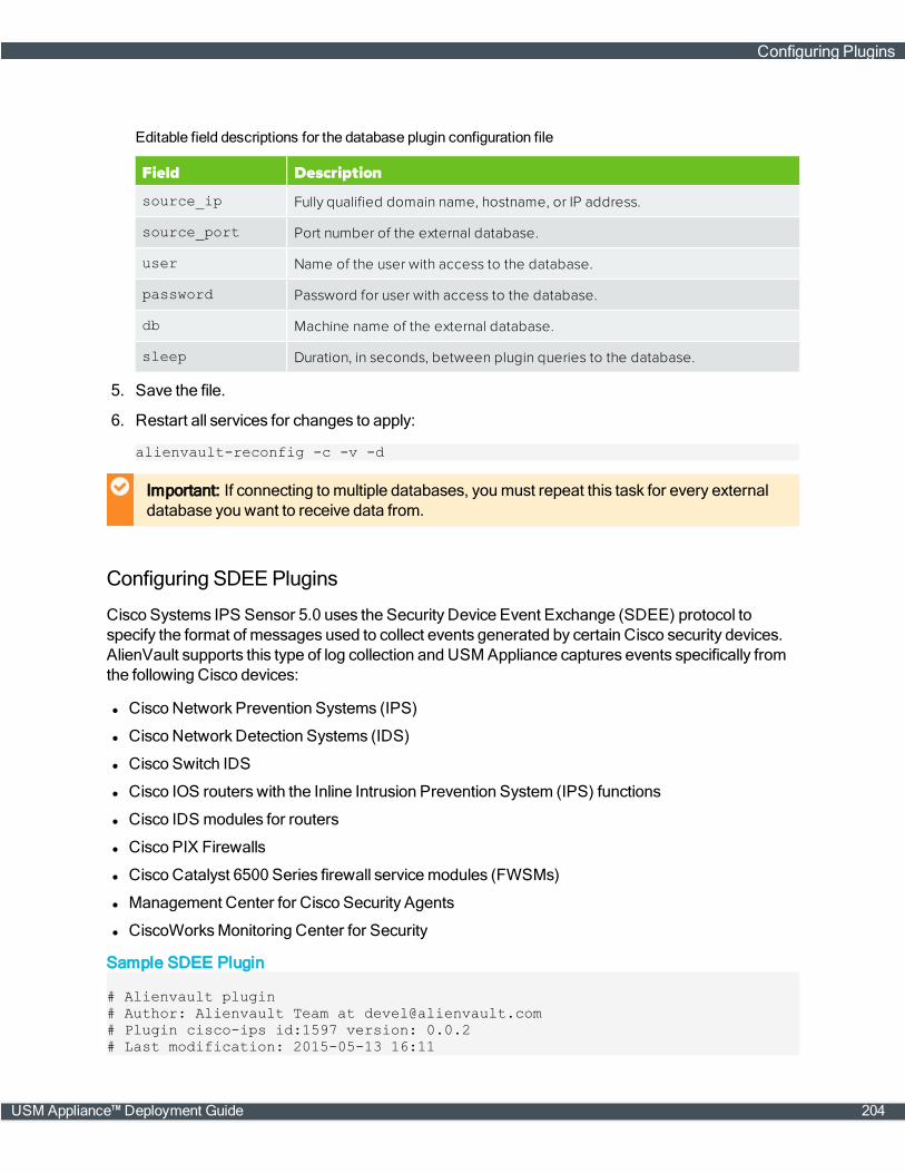
Field Description
source_ip Fully qualified domain name, hostname, or IP address.
source_port Port number of the external database.
user Name of the user with access to the database.
password Password for user with access to the database.
db Machine name of the external database.
sleep Duration, in seconds, between plugin queries to the database.
Editable field descriptions for the database plugin configuration file
5. Save the file.
6. Restart all services for changes to apply:
alienvault-reconfig -c -v -d
Important: If connecting tomultiple databases, youmust repeat this task for every externaldatabase you want to receive data from.
Configuring SDEEPlugins
Cisco Systems IPS Sensor 5.0 uses the Security Device Event Exchange (SDEE) protocol tospecify the format of messages used to collect events generated by certain Cisco security devices.AlienVault supports this type of log collection and USM Appliance captures events specifically fromthe following Cisco devices:
l Cisco Network Prevention Systems (IPS)
l Cisco Network Detection Systems (IDS)
l Cisco Switch IDS
l Cisco IOS routers with the Inline Intrusion Prevention System (IPS) functions
l Cisco IDS modules for routers
l Cisco PIX Firewalls
l Cisco Catalyst 6500 Series firewall servicemodules (FWSMs)
l Management Center for Cisco Security Agents
l CiscoWorksMonitoring Center for Security
Sample SDEE Plugin
# Alienvault plugin# Author: Alienvault Team at [email protected]# Plugin cisco-ips id:1597 version: 0.0.2# Last modification: 2015-05-13 16:11
Configuring Plugins
USM Appliance™ Deployment Guide 204
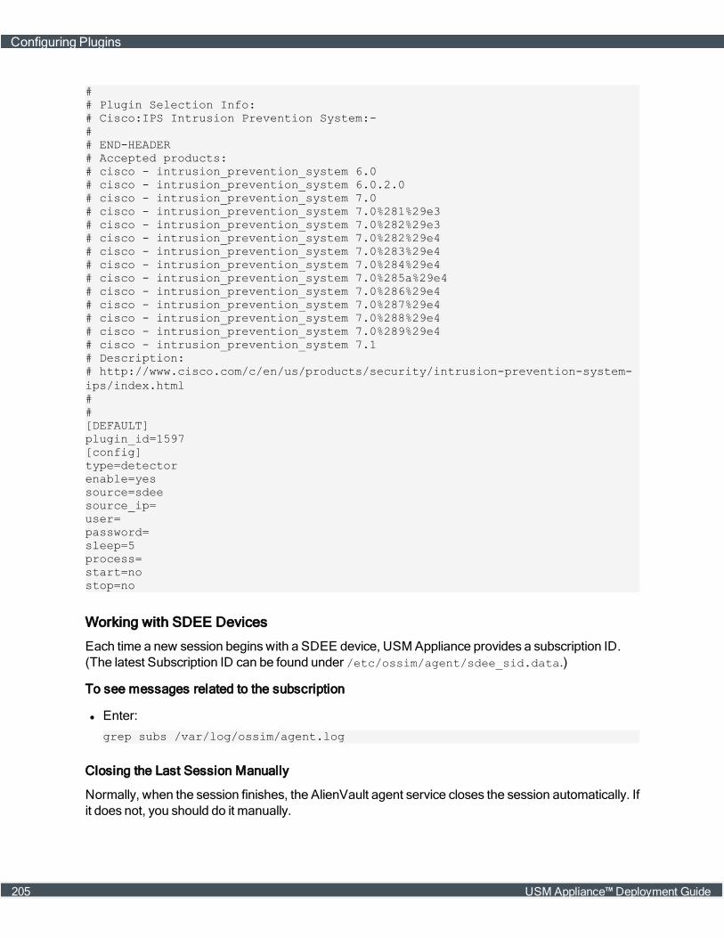
## Plugin Selection Info:# Cisco:IPS Intrusion Prevention System:-## END-HEADER# Accepted products:# cisco - intrusion_prevention_system 6.0# cisco - intrusion_prevention_system 6.0.2.0# cisco - intrusion_prevention_system 7.0# cisco - intrusion_prevention_system 7.0%281%29e3# cisco - intrusion_prevention_system 7.0%282%29e3# cisco - intrusion_prevention_system 7.0%282%29e4# cisco - intrusion_prevention_system 7.0%283%29e4# cisco - intrusion_prevention_system 7.0%284%29e4# cisco - intrusion_prevention_system 7.0%285a%29e4# cisco - intrusion_prevention_system 7.0%286%29e4# cisco - intrusion_prevention_system 7.0%287%29e4# cisco - intrusion_prevention_system 7.0%288%29e4# cisco - intrusion_prevention_system 7.0%289%29e4# cisco - intrusion_prevention_system 7.1# Description:# http://www.cisco.com/c/en/us/products/security/intrusion-prevention-system-ips/index.html##[DEFAULT]plugin_id=1597[config]type=detectorenable=yessource=sdeesource_ip=user=password=sleep=5process=start=nostop=no
Working with SDEE Devices
Each time a new session beginswith a SDEE device, USM Appliance provides a subscription ID.(The latest Subscription ID can be found under /etc/ossim/agent/sdee_sid.data.)
To see messages related to the subscription
l Enter:
grep subs /var/log/ossim/agent.log
Closing the Last Session Manually
Normally, when the session finishes, the AlienVault agent service closes the session automatically. Ifit does not, you should do it manually.
Configuring Plugins
205 USM Appliance™ Deployment Guide
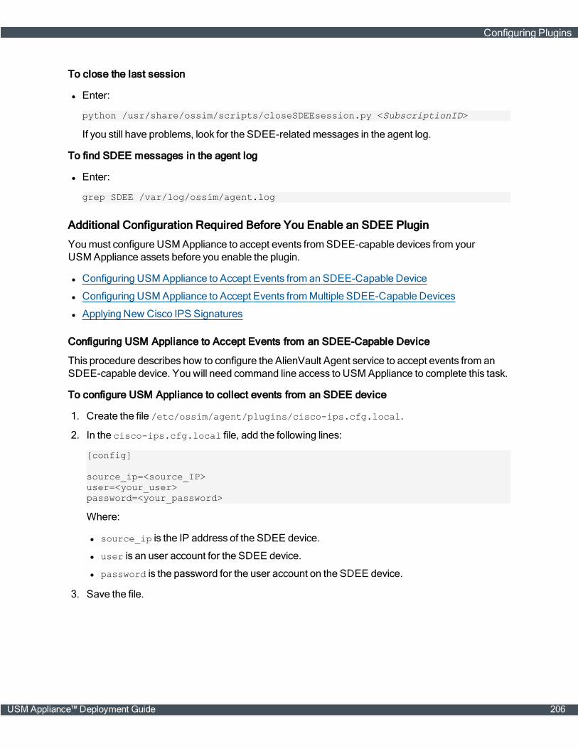
To close the last session
l Enter:
python /usr/share/ossim/scripts/closeSDEEsession.py <SubscriptionID>
If you still have problems, look for the SDEE-relatedmessages in the agent log.
To find SDEE messages in the agent log
l Enter:
grep SDEE /var/log/ossim/agent.log
Additional Configuration Required Before You Enable an SDEE Plugin
Youmust configure USM Appliance to accept events fromSDEE-capable devices from yourUSM Appliance assets before you enable the plugin.
l Configuring USM Appliance to Accept Events from an SDEE-Capable Device
l Configuring USM Appliance to Accept Events fromMultiple SDEE-Capable Devices
l Applying New Cisco IPS Signatures
Configuring USM Appliance to Accept Events from an SDEE-Capable Device
This procedure describes how to configure the AlienVault Agent service to accept events from anSDEE-capable device. You will need command line access to USM Appliance to complete this task.
To configure USM Appliance to collect events from an SDEE device
1. Create the file /etc/ossim/agent/plugins/cisco-ips.cfg.local.
2. In the cisco-ips.cfg.local file, add the following lines:
[config]
source_ip=<source_IP>user=<your_user>password=<your_password>
Where:
l source_ip is the IP address of the SDEE device.
l user is an user account for the SDEE device.
l password is the password for the user account on the SDEE device.
3. Save the file.
Configuring Plugins
USM Appliance™ Deployment Guide 206

Configuring USM Appliance to Accept Events from Multiple SDEE-Capable Devices
This procedure describes how to configure the AlienVault Agent service to accept events frommultiple SDEE-capable devices. You will need command line access to USM Appliance to completethis task.
To configure USM Appliance to collect events from multiple SDEE devices
1. Create the file /etc/ossim/agent/cisco_sdee.csv.
2. In the .csv file, specify the IP addresses for the different SDEE devices and their login cre-dentials. Youmust enter one device per line:
1.2.3.4,user1,pass11.2.3.5,user2,pass21.2.3.6,user3,pass3
Important: Youmust not have any empty line after the credentials.
3. Create the file /etc/ossim/agent/plugins/cisco-ips.cfg.local.
4. In the cisco-ips.cfg.local file add the following lines. The #means to comment out thosethree lines.
[config]
#source_ip=#user=#password=
credentials_file=/etc/ossim/agent/cisco_sdee.csv
5. Save the file.
Note: You can now enable the SDEE plugin. See Enabling Plugins, on page 189.
Applying New Cisco IPS Signatures
Occasionally youmay download or receive new signatures for your Cisco IPS devices. If you want touse those signatures in USM Appliance, you will need to update the USM Appliance databasemanually. You will need command line access to USM Appliance to complete this task.
To populate the USM Appliance database with new signatures
1. Go to /usr/share/ossim/scripts/ and execute the following script to generate the plugin sidinformation:
python createCiscoIPSSidmap.py <signature_file>.xml > sdee.sql
where <signature_file>.xml is the file you downloaded or received fromCisco.
This script generates the sql needed to update the USM Appliance database:
DELETE FROM plugin WHERE id = "1597";
Configuring Plugins
207 USM Appliance™ Deployment Guide
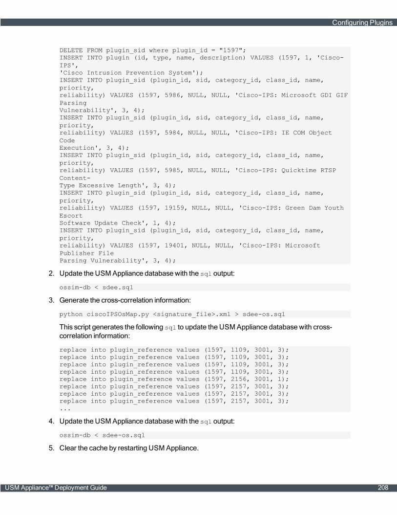
DELETE FROM plugin_sid where plugin_id = "1597";INSERT INTO plugin (id, type, name, description) VALUES (1597, 1, 'Cisco-IPS','Cisco Intrusion Prevention System');INSERT INTO plugin_sid (plugin_id, sid, category_id, class_id, name,priority,reliability) VALUES (1597, 5986, NULL, NULL, 'Cisco-IPS: Microsoft GDI GIFParsingVulnerability', 3, 4);INSERT INTO plugin_sid (plugin_id, sid, category_id, class_id, name,priority,reliability) VALUES (1597, 5984, NULL, NULL, 'Cisco-IPS: IE COM ObjectCodeExecution', 3, 4);INSERT INTO plugin_sid (plugin_id, sid, category_id, class_id, name,priority,reliability) VALUES (1597, 5985, NULL, NULL, 'Cisco-IPS: Quicktime RTSPContent-Type Excessive Length', 3, 4);INSERT INTO plugin_sid (plugin_id, sid, category_id, class_id, name,priority,reliability) VALUES (1597, 19159, NULL, NULL, 'Cisco-IPS: Green Dam YouthEscortSoftware Update Check', 1, 4);INSERT INTO plugin_sid (plugin_id, sid, category_id, class_id, name,priority,reliability) VALUES (1597, 19401, NULL, NULL, 'Cisco-IPS: MicrosoftPublisher FileParsing Vulnerability', 3, 4);
2. Update the USM Appliance database with the sql output:
ossim-db < sdee.sql
3. Generate the cross-correlation information:
python ciscoIPSOsMap.py <signature_file>.xml > sdee-os.sql
This script generates the following sql to update the USM Appliance database with cross-correlation information:
replace into plugin_reference values (1597, 1109, 3001, 3);replace into plugin_reference values (1597, 1109, 3001, 3);replace into plugin_reference values (1597, 1109, 3001, 3);replace into plugin_reference values (1597, 1109, 3001, 3);replace into plugin_reference values (1597, 2156, 3001, 1);replace into plugin_reference values (1597, 2157, 3001, 3);replace into plugin_reference values (1597, 2157, 3001, 3);replace into plugin_reference values (1597, 2157, 3001, 3);...
4. Update the USM Appliance database with the sql output:
ossim-db < sdee-os.sql
5. Clear the cache by restarting USM Appliance.
Configuring Plugins
USM Appliance™ Deployment Guide 208
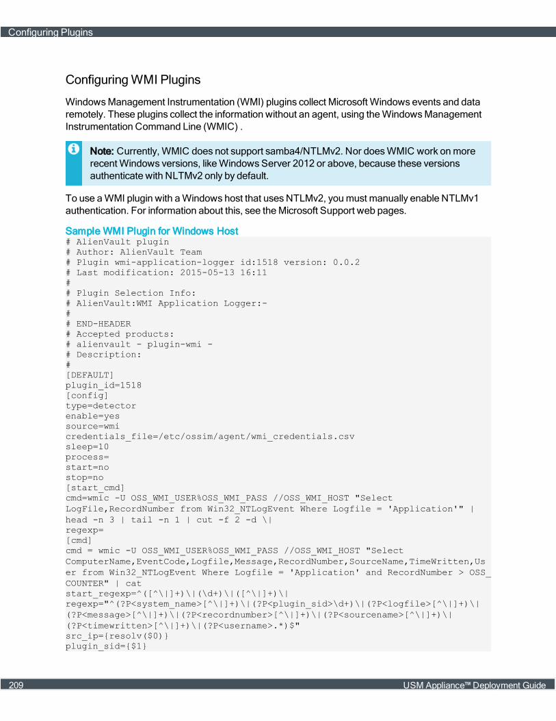
ConfiguringWMI Plugins
WindowsManagement Instrumentation (WMI) plugins collect Microsoft Windows events and dataremotely. These plugins collect the information without an agent, using theWindowsManagementInstrumentation Command Line (WMIC) .
Note: Currently, WMIC does not support samba4/NTLMv2. Nor doesWMIC work onmorerecentWindows versions, likeWindowsServer 2012 or above, because these versionsauthenticate with NLTMv2 only by default.
To use aWMI plugin with aWindows host that usesNTLMv2, youmust manually enable NTLMv1authentication. For information about this, see theMicrosoft Support web pages.
Sample WMI Plugin for Windows Host# AlienVault plugin# Author: AlienVault Team# Plugin wmi-application-logger id:1518 version: 0.0.2# Last modification: 2015-05-13 16:11## Plugin Selection Info:# AlienVault:WMI Application Logger:-## END-HEADER# Accepted products:# alienvault - plugin-wmi -# Description:#[DEFAULT]plugin_id=1518[config]type=detectorenable=yessource=wmicredentials_file=/etc/ossim/agent/wmi_credentials.csvsleep=10process=start=nostop=no[start_cmd]cmd=wmic -U OSS_WMI_USER%OSS_WMI_PASS //OSS_WMI_HOST "SelectLogFile,RecordNumber from Win32_NTLogEvent Where Logfile = 'Application'" |head -n 3 | tail -n 1 | cut -f 2 -d \|regexp=[cmd]cmd = wmic -U OSS_WMI_USER%OSS_WMI_PASS //OSS_WMI_HOST "SelectComputerName,EventCode,Logfile,Message,RecordNumber,SourceName,TimeWritten,User from Win32_NTLogEvent Where Logfile = 'Application' and RecordNumber > OSS_COUNTER" | catstart_regexp=^([^\|]+)\|(\d+)\|([^\|]+)\|regexp="^(?P<system_name>[^\|]+)\|(?P<plugin_sid>\d+)\|(?P<logfile>[^\|]+)\|(?P<message>[^\|]+)\|(?P<recordnumber>[^\|]+)\|(?P<sourcename>[^\|]+)\|(?P<timewritten>[^\|]+)\|(?P<username>.*)$"src_ip={resolv($0)}plugin_sid={$1}
Configuring Plugins
209 USM Appliance™ Deployment Guide
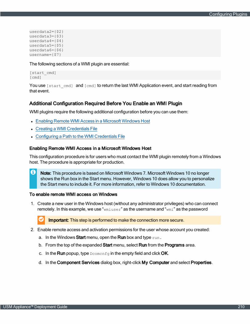
userdata2={$2}userdata3={$3}userdata4={$4}userdata5={$5}userdata6={$6}username={$7}
The following sections of aWMI plugin are essential:
[start_cmd][cmd]
You use [start_cmd] and [cmd] to return the last WMI Application event, and start reading fromthat event.
Additional Configuration Required Before You Enable an WMI Plugin
WMI plugins require the following additional configuration before you can use them:
l Enabling RemoteWMI Access in aMicrosoft WindowsHost
l Creating aWMI Credentials File
l Configuring a Path to theWMI Credentials File
Enabling Remote WMI Access in a Microsoft Windows Host
This configuration procedure is for users whomust contact theWMI plugin remotely from aWindowshost. The procedure is appropriate for production.
Note: This procedure is based onMicrosoft Windows 7. Microsoft Windows 10 no longershows the Run box in the Start menu. However, Windows 10 does allow you to personalizethe Start menu to include it. For more information, refer toWindows 10 documentation.
To enable remote WMI access on Windows
1. Create a new user in theWindows host (without any administrator privileges) who can connectremotely. In this example, we use “wmiuser” as the username and “wmi” as the password
Important: This step is performed tomake the connection more secure.
2. Enable remote access and activation permissions for the user whose account you created:
a. In theWindowsStart menu, open the Run box and type run.
b. From the top of the expanded Start menu, select Run from the Programs area.
c. In the Run popup, type Dcomcnfg in the empty field and clickOK.
d. In the Component Services dialog box, right-clickMy Computer and select Properties.
Configuring Plugins
USM Appliance™ Deployment Guide 210

e. Click the COM Security tab, then Edit Limits under Access Permissions.
f. Select ANONYMOUS LOGON, Remote Access, clickOK, then Apply.
Configuring Plugins
211 USM Appliance™ Deployment Guide
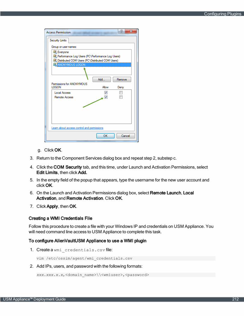
g. ClickOK.
3. Return to the Component Services dialog box and repeat step 2, substep c.
4. Click the COM Security tab, and this time, under Launch and Activation Permissions, selectEdit Limits, then click Add.
5. In the empty field of the popup that appears, type the username for the new user account andclickOK.
6. On the Launch and Activation Permissions dialog box, select Remote Launch, LocalActivation, and Remote Activation. ClickOK.
7. Click Apply, thenOK.
Creating a WMI Credentials File
Follow this procedure to create a file with your Windows IP and credentials on USM Appliance. Youwill need command line access to USM Appliance to complete this task.
To configure AlienVaultUSM Appliance to use a WMI plugin
1. Create a wmi_credentials.csv file:
vim /etc/ossim/agent/wmi_credentials.csv
2. Add IPs, users, and password with the following formats:
xxx.xxx.x.x,<domain_name>\\<wmiuser>,<password>
Configuring Plugins
USM Appliance™ Deployment Guide 212
Example
233.200.7.0, mydomain_name\\mr_big,uguessed1t
If you do not use a domain, enter the following instead:
xxx.xxx.x.x, <username>,<password>
3. Save the file.
Configuring a Path to the WMI Credentials File
In order for theWMI plugin to work correctly, youmust update the plugin with the path to the wmi_credentials.csv file you just created. You will need command line access to USM Appliance tocomplete this task.
To specify the path to the WMI credentials file
1. Depending on which plugin you've enabled, locate theWMI configuration file or files in yourUSM Appliance instance. Potential file locationsmight be any of the following:
/etc/ossim/agent/plugins/wmi-application-logger.cfg/etc/ossim/agent/plugins/wmi-monitor.cfg/etc/ossim/agent/plugins/wmi-security-logger-srv2008.cfg/etc/ossim/agent/plugins/wmi-security-logger.cfg/etc/ossim/agent/plugins/wmi-system-logger.cfg
2. Create the file <wmi-xxxx-plugin>.cfg.local based on your choice and enter the path toyour wmi_credentials.csv file in the credentials_file field.
Example
[config]credentials_file=/etc/ossim/agent/wmi_credentials.csv
3. Save the file.
ConfiguringMonitor Plugins
While detector plugins generate events using information from logs, databases, or queries to othersystems, monitor plugins execute commands in USM Appliance to check the status of the target theymonitor.
Monitor plugins aremeant to be used from directives to request information from systems. Theyreturn the system status when the target theymonitor makes a request. Target examples includenmap, ping, whois, and tcptrack.
Note: You need to enable aMonitor plugin before you can use it in a directive. For informationabout directives, see About Correlation Directives.
Monitor plugins also generate text logs consumed by syslog, like standard logs. They help correlatelog events into alarms bymatching events against the current status of USM Appliance.
Configuring Plugins
213 USM Appliance™ Deployment Guide
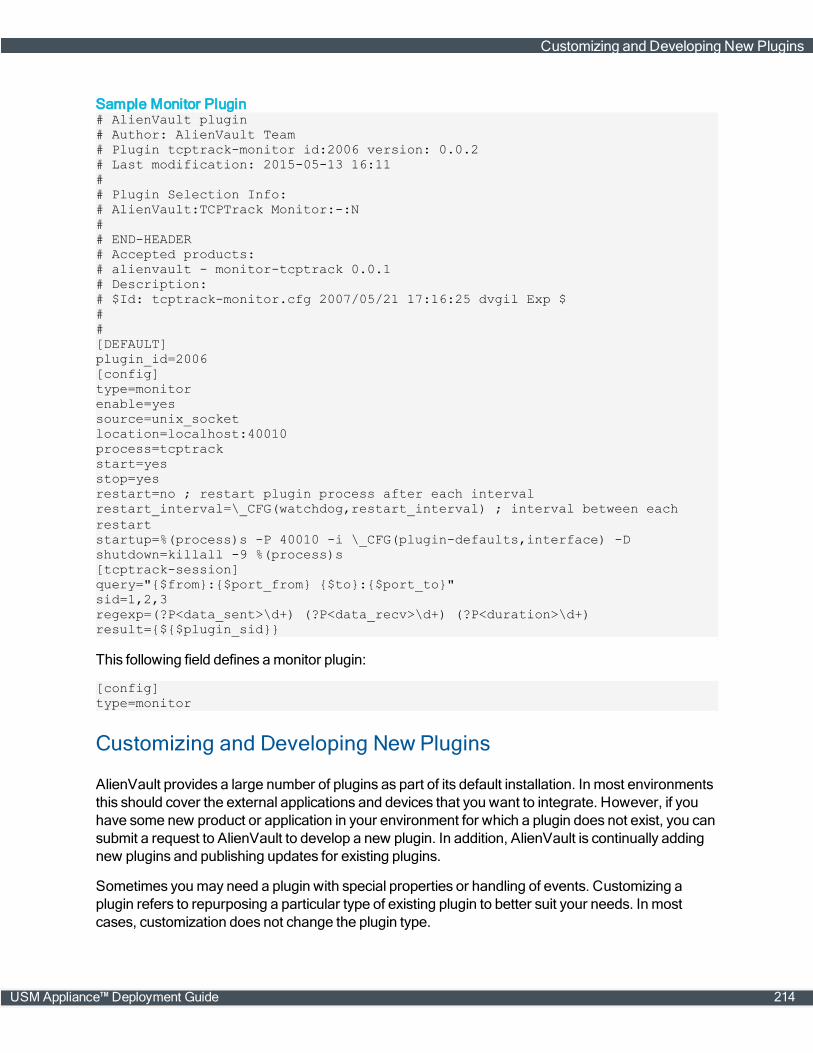
Sample Monitor Plugin# AlienVault plugin# Author: AlienVault Team# Plugin tcptrack-monitor id:2006 version: 0.0.2# Last modification: 2015-05-13 16:11## Plugin Selection Info:# AlienVault:TCPTrack Monitor:-:N## END-HEADER# Accepted products:# alienvault - monitor-tcptrack 0.0.1# Description:# $Id: tcptrack-monitor.cfg 2007/05/21 17:16:25 dvgil Exp $##[DEFAULT]plugin_id=2006[config]type=monitorenable=yessource=unix_socketlocation=localhost:40010process=tcptrackstart=yesstop=yesrestart=no ; restart plugin process after each intervalrestart_interval=\_CFG(watchdog,restart_interval) ; interval between eachrestartstartup=%(process)s -P 40010 -i \_CFG(plugin-defaults,interface) -Dshutdown=killall -9 %(process)s[tcptrack-session]query="{$from}:{$port_from} {$to}:{$port_to}"sid=1,2,3regexp=(?P<data_sent>\d+) (?P<data_recv>\d+) (?P<duration>\d+)result={${$plugin_sid}}
This following field defines amonitor plugin:
[config]type=monitor
Customizing and Developing New Plugins
AlienVault provides a large number of plugins as part of its default installation. In most environmentsthis should cover the external applications and devices that you want to integrate. However, if youhave some new product or application in your environment for which a plugin does not exist, you cansubmit a request to AlienVault to develop a new plugin. In addition, AlienVault is continually addingnew plugins and publishing updates for existing plugins.
Sometimes youmay need a plugin with special properties or handling of events. Customizing aplugin refers to repurposing a particular type of existing plugin to better suit your needs. In mostcases, customization does not change the plugin type.
Customizing and Developing New Plugins
USM Appliance™ Deployment Guide 214
Developing a plugin refers to creating a new plugin from scratch, typically to collect event from aparticular device type for which no plugin currently exists. To create a new plugin, you can edit andconfigure all the plugin's configuration and regex settings by hand, or you can use the plugin builderwizard built into the USMAppliance webUI to simplify the process.
This section providesmore information using each of thesemethods of customizing or creating newUSM Appliance plugins. Topics included in this section are the following:
Plugin Design Fundamentals
Customizing an Existing Plugin
Creating New Plugins Using the Plugin Builder
Developing New Plugins fromScratch
Plugin Design Fundamentals
TheUSM Appliance Sensor uses plugins to extract and normalize data received from different datasources.
Note: You can examine which data sources are supported by default by examining the contentof the /etc/ossim/agent/plugins directory, or by examining listed data sources in theAlienVault console or in the USM Appliance webUI.
During data normalization, a plugin evaluates each log file line and translates it to an event thatidentifies the event’s type and subtype within the USM Appliance Event Taxonomy.
Each USM Appliance plugin consist of two files:
l <plugin_name>.cfg — Resides on each USM Appliance Sensor under/etc/ossim/agent/plugins. This file specifies the plugin configuration parameters, and therules a log linemust match before USM Appliance collects and normalizes them.
These parameters include:
o Plugin type and location of received data that the plugin can read from.
o Regular expressions and rules needed to parse logs in saved data.
l <plugin_name>.sql — Resides on the USM Appliance Server under /usr/share/doc/ossim-mysql/contrib/plugins. This file describes every event, and the corresponding event fields,that the pluginmay store in the SIEM database for events extracted from a data source:
o Plugin ID
o Event type ID
o Name assigned to an event
o Database fields written for each event
Customizing and Developing New Plugins
215 USM Appliance™ Deployment Guide
o Priority and reliability values
l Note: See Plugin .SQL Files for more information and an illustration of the contents of theplugin .sql file associated with every plugin.
Plugin Configuration File Structure
The following figure shows an example of the .cfg data source plugin file. The file shown in thisexample enables the USMAppliance Sensor to parse SSH events.
Customizing and Developing New Plugins
USM Appliance™ Deployment Guide 216
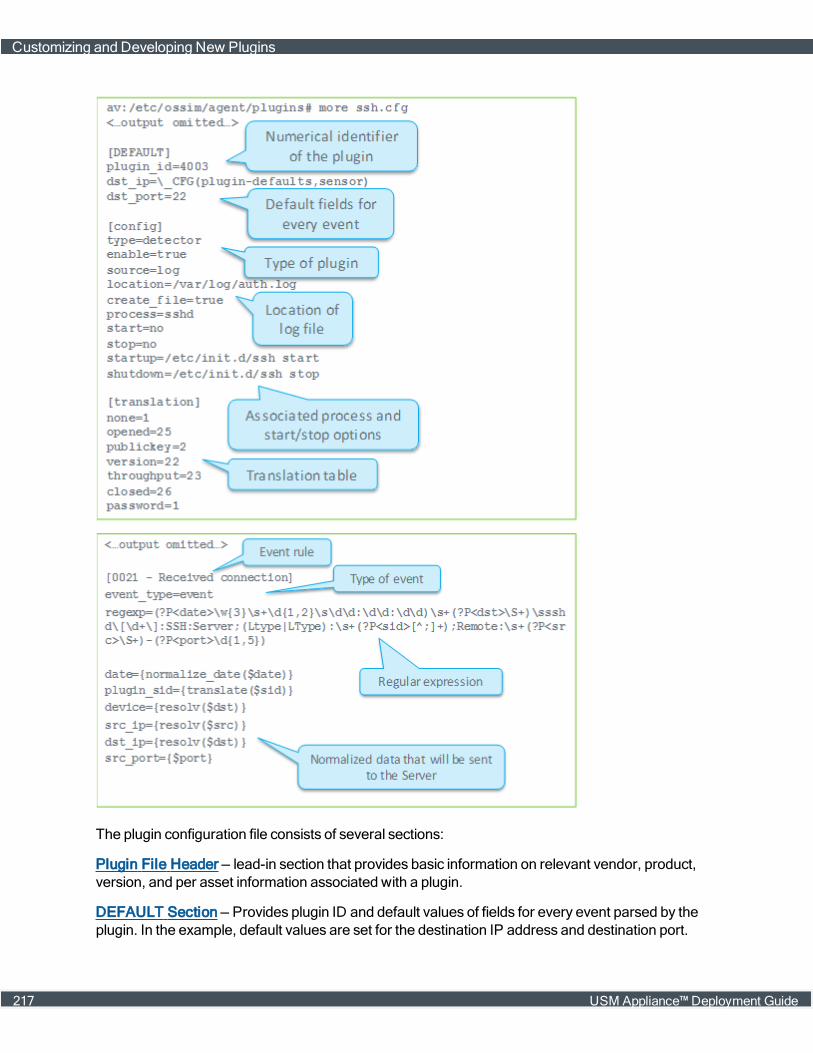
The plugin configuration file consists of several sections:
Plugin File Header — lead-in section that provides basic information on relevant vendor, product,version, and per asset information associated with a plugin.
DEFAULT Section — Provides plugin ID and default values of fields for every event parsed by theplugin. In the example, default values are set for the destination IP address and destination port.
Customizing and Developing New Plugins
217 USM Appliance™ Deployment Guide
Config Section — Defines the plugin type, whether a plugin is enabled, source of the plugin, locationof a log file the plugin is reading from, and associated processes and start and stop functions.
Translation Section — Provides translation and conversion of extracted log token and other text andnumeric data to values stored in the SIEM database.
Rules Section — Used to define one rule for each event that may come from a data source. Eachrule is composed of a regular expression that defines how to extract information from log events, andmapping between extracted information and the normalized event fields. In the example, only onerule is shown on the right side of the slide for the sake of readability.
Plugin File Header
All plugin configuration filesmust include a header, even if it is empty of content:
# AlienVault plugin# Author: AlienVault Team# Plugin {{ plugin_name }} id:{{ plugin_id }} version: -# Last modification: {{ LAST_MODIFICATION_DATE }}## Plugin Selection Info:# {{vendor}}:{{model}}:{{version}}:{{per_asset}}## END-HEADER## Accepted products:## Description
The Plugin Selection Info: section includes relevant vendor, product, version, and per assetinformation.
l Product and Vendor Information — Express the product name and vendor information for the plu-gin, using the following format: Fortinet:Fortigate. In this example, Fortigate is the productand Fortinet is the vendor of that product.
l Version Information — The version information allows you to select the right plugin whenmultipleplugins exist for any one version, or when there aremultiple plugins, based on log format or inten-ded output.
All plugins set version information to "-" out of the box, because not all applications use versions.Should this be the case for your plugin, you can just maintain the default setting of the versionfield. When customizing or creating new plugins, verify whether or not your plugin is versionedand, if so, add the version information.
l Per Asset Information — Some pluginsmust be activated for each asset in your network. If PerAssets is not set, USM Appliance defaults to "Yes" (Y) and activates the plugin on each asset.
If your plugin should not be activated per asset (monitor plugins, for example), Per Assetmustread "No" (N).
DEFAULT Section
The [DEFAULT] section of the plugin configuration file specifies the plugin_id, which is a unique
Customizing and Developing New Plugins
USM Appliance™ Deployment Guide 218

ID for the plugin data source. For example, plugin_id=4003 is a plugin for OpenSSH. The plugin IDis also used when referring to plugins in correlation rules, and when defining policies in USMAppliance.
Users can use the range of 9001 to 2147483647 as plugin IDs, except for the following valueswhichare reserved:
90003, 90005, 90007, 90008, 10002, 12001, 19004, 19005, 19006, 20505
Config Section
The [config] section of the plugin configuration file specifies the basic settings for this plugin. Forexample
l type — specifies the plugin type, detector or monitor.
l enable — specifies whether the plugin is enabled or not.
l source — identifies the plugin source, using the following keywords:
l log: Text log file (for example: SSH, Apache)
l mssql: Microsoft SQL Server database (for example: panda-se)
l mysql: MySQL database (for example: moodle)
l wmi: WindowsManagement Instrumentation (wmi-system-logger)
l location — specifies the name and location of the log file the plugin is reading from, for example,location=/var/log/file.log.The rsyslog rules define the location of log files used to storeincoming logs from different data sources.
Note: Location is present only in plugins that use a log as a source. Plugins that use othersources contain other plugin-specific information (for example, how to connect to aMySQLdatabase).
Translation Section
The [translation] section translate token values of a source log and assign them to a normalizedevent field. Translations are useful when you have similar logmessages that describe differentevents, such aswhen the difference betweenmessages is only in the value of a token and not thestructure of themessage itself. In this situation, you can use only one rule to parse differentmessages and use translations to translate (non-numeric)values frommessages to numeric valuesthat can be used as plugin_sid (event type ID) values.
Translations consist of two parts:
l Translation table — Defines themapping between values in logmessages and values in nor-malized event.
l translate() function — Translates values from tokens into values in normalized event fields by fol-lowing the translation table.
Customizing and Developing New Plugins
219 USM Appliance™ Deployment Guide

In the sample configuration file (shown in the ssh.cfg illustration), the “sid” token in the logmessagecan take the following non-numeric values: none, opened, publickey, version, throughput, closed,and password. Different values of the sid token indicate different logmessages. Values of the sidtoken are translated into numeric values as defined by the translation table, and then used as theplugin_sid value for individual events. Translations can also be defined to convert other text values tonumbers aswell.
Rules Section
The rest of the plugin configuration file belongs to the rules section. It contains rules that define theformat of each event and how data extracted by a regular expression for each event will benormalized into standard event fields. Each rule in a plugin is defined with a name and the eventtype, which is defined using the event_type=event line in the plugin configuration file.
The regexp field contains the regular expression that defines the format of the events, and extractsthe information to normalize it. The regular expressions are written using Python regular expressionsyntax.
[0000 - Failed password]event_type=eventregexp=(?P<date>\w{3}\s+\d{1,2}\s\d\d:\d\d:\d\d)\s+(?P<dst>\S+) sshd\[\d+\]:Failed password for\s(?P<info>invalid user\s)?(?P<user>\S+)\sfrom\s(?P<src>\S+)\sport\s(?P<sport>\d{1,5})date={normalize_date($date)}plugin_sid=1src_ip={resolv($src)}dst_ip={resolv($dst)}src_port={$sport}username={$user}userdata1={$info}userdata2={$dst}device={resolv($dst)}
Note: For more information about the syntax or construction of regular expressions, refer toresources on the subject available on the Internet. Youmay also want to check outAlienVault® Training courses that providemore information and hands-on labs covering plugindevelopment and, in particular, regular expressions used to define plugin rules.
Customizing and Developing New Plugins
USM Appliance™ Deployment Guide 220
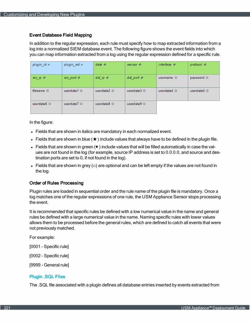
Event Database Field Mapping
In addition to the regular expression, each rulemust specify how tomap extracted information from alog into a normalized SIEM database event. The following figure shows the event fields into whichyou canmap information extracted from a log using the regular expression defined for a specific rule.
In the figure:
l Fields that are shown in italics aremandatory in each normalized event.
l Fields that are shown in blue (★) include values that always have to be defined in the plugin file.
l Fields that are shown in green (♦ ) include values that will be filled automatically in case the val-ues are not found in the log (for example, source IP address is set to 0.0.0.0, and source and des-tination ports are set to 0, if not found in the log).
l Fields that are shown in grey (ᴑ) are optional and can be left empty if the values are not found inthe log.
Order of Rules Processing
Plugin rules are loaded in sequential order and the rule name of the plugin file ismandatory. Once alogmatches one of the regular expressions of one rule, the USMAppliance Sensor stops processingthe event.
It is recommended that specific rules be defined with a low numerical value in the name and generalrules be defined with a large numerical value in the name. Naming specific rules with lower valuesallows them to be processed before the general rules, which are defined to catch all events that werenot previouslymatched.
For example:
[0001 - Specific rule]
[0002 - Specific rule]
[9999 - General rule]
Plugin .SQL Files
The .SQL file associated with a plugin defines all database entries inserted by events extracted from
Customizing and Developing New Plugins
221 USM Appliance™ Deployment Guide

the plugin source data or log file. The following illustration shows the ssh.sql file associated withthe ssh.cfg file described in previous sections.
After enabling a plugin, you need tomport the corresponding plugin .sql file to the SIEM databaseusing the following command:
cat <plugin_name>.sql | ossim-db
Using Functions to Format Event Field Data
The USM Appliance Server must receive normalized events in a predefined format. USM Applianceprovides a number of built-in functions you can used to convert the extracted data obtained from theregular expressions of specific plugin rules to the format expected in normalized USM Applianceevent fields.
For example, time and date in USMAppliance is in the format YYYY-MM-DD HH:MM:SS (for example,2013-12-31 22:57:00), but different data sourcesmay use different formats for time and date.You can use the normalize_date() function, which simplifies the process of normalizing events, byconverting different time formats into the format accepted by the server.
Another function that can be used is the resolv() function, which translates hostnames into IPv4addresses by performing DNS queries.
date={normalize_date($date)}plugin_sid={translate($type)}dst_ip={resolv($dst_ip)}src_ip={resolv($src_ip)}
The following table provides a summary of the built-in USM Appliance functions:
Function Description
$CONCAT($val1, $val2, chars) Concatenates the values and characters passed as parameters
geoip_getCity(ipaddr) Gets the corresponding city according to the builtin Geo-IP database.
Customizing and Developing New Plugins
USM Appliance™ Deployment Guide 222
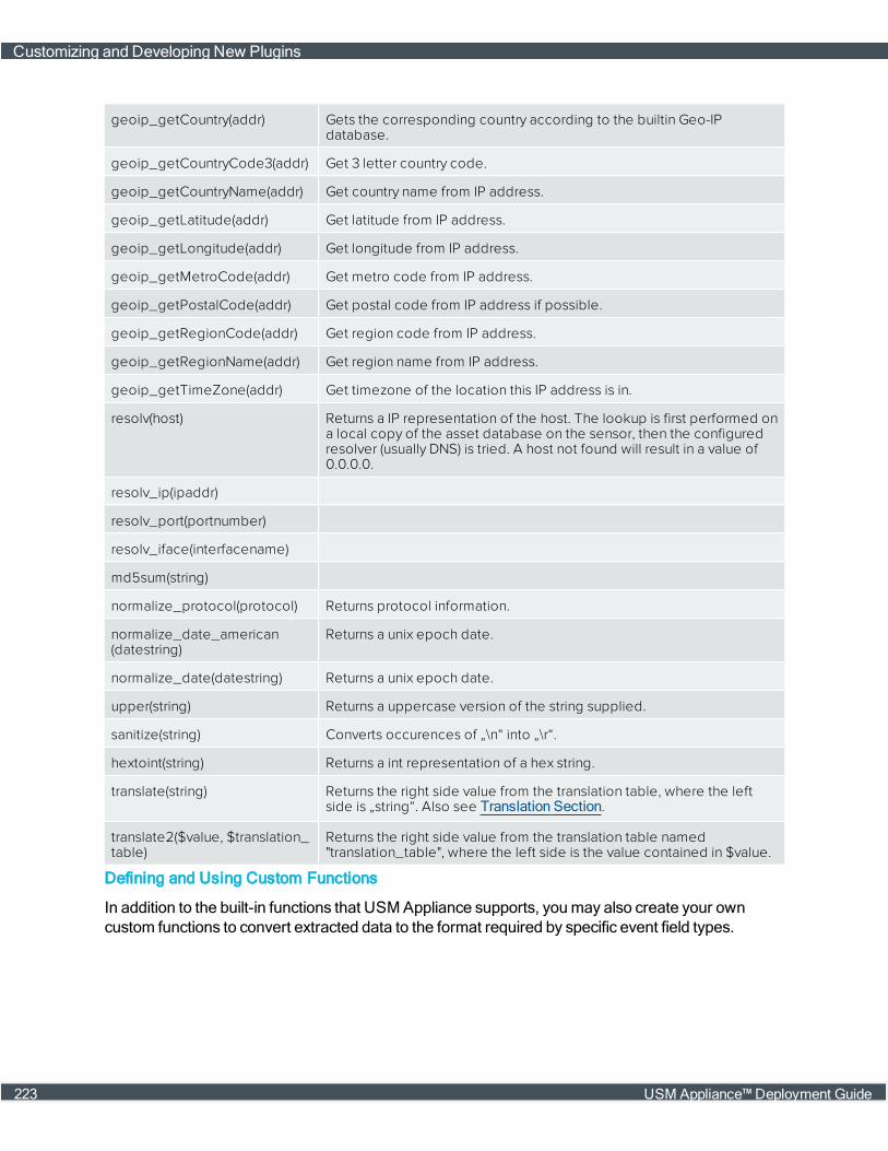
geoip_getCountry(addr) Gets the corresponding country according to the builtin Geo-IPdatabase.
geoip_getCountryCode3(addr) Get 3 letter country code.
geoip_getCountryName(addr) Get country name from IP address.
geoip_getLatitude(addr) Get latitude from IP address.
geoip_getLongitude(addr) Get longitude from IP address.
geoip_getMetroCode(addr) Get metro code from IP address.
geoip_getPostalCode(addr) Get postal code from IP address if possible.
geoip_getRegionCode(addr) Get region code from IP address.
geoip_getRegionName(addr) Get region name from IP address.
geoip_getTimeZone(addr) Get timezone of the location this IP address is in.
resolv(host) Returns a IP representation of the host. The lookup is first performed ona local copy of the asset database on the sensor, then the configuredresolver (usually DNS) is tried. A host not found will result in a value of0.0.0.0.
resolv_ip(ipaddr)
resolv_port(portnumber)
resolv_iface(interfacename)
md5sum(string)
normalize_protocol(protocol) Returns protocol information.
normalize_date_american(datestring)
Returns a unix epoch date.
normalize_date(datestring) Returns a unix epoch date.
upper(string) Returns a uppercase version of the string supplied.
sanitize(string) Converts occurences of „\n“ into „\r“.
hextoint(string) Returns a int representation of a hex string.
translate(string) Returns the right side value from the translation table, where the leftside is „string“. Also see Translation Section.
translate2($value, $translation_table)
Returns the right side value from the translation table named"translation_table", where the left side is the value contained in $value.
Defining and Using Custom Functions
In addition to the built-in functions that USM Appliance supports, youmay also create your owncustom functions to convert extracted data to the format required by specific event field types.
Customizing and Developing New Plugins
223 USM Appliance™ Deployment Guide
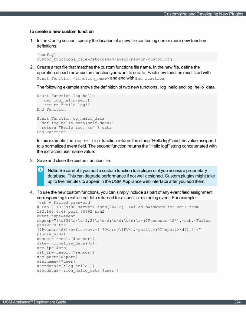
To create a new custom function
1. In the Config section, specify the location of a new file containing one or more new functiondefinitions.
[config]custom_functions_file=/etc/ossim/agent/plugin/custom.cfg
2. Create a text file that matches the custom functions file name. In the new file, define theoperation of each new custom function you want to create, Each new functionmust start withStart Function <function_name> and end with End function.
The following example shows the definition of two new functions , log_hello and log_hello_data.
Start Function log_hellodef log_hello(self):return "Hello log!"
End Function
Start Function og_hello_datadef log_hello_data(self,data):return "Hello log: %s" % data
End Function
In this example, the log_hello() function returns the string "Hello log!" and the value assignedto a normalized event field. The second function returns the "Hello log!" string concatenated withthe extracted user name value.
3. Save and close the custom function file.
Note: Be careful if you add a custom function to a plugin or if you access a proprietarydatabase. This can degrade performance if not well designed. Custom pluginsmight takeup to fiveminutes to appear in the USM Appliance web interface after you add them.
4. To use the new custom functions, you can simply include as part of any event field assignmentcorresponding to extracted data returned for a specific rule or log event. For example:[ssh - Failed password]# Feb 8 10:09:06 server1 sshd[24472]: Failed password for dgil from192.168.6.69 port 33992 ssh2event_type=eventregexp="(\w{3}\s+\d{1,2}\s\d\d:\d\d:\d\d)\s+(?P<sensor>\S*).*ssh.*Failedpassword for(?P<user>\S+)\s+from\s+.*?(?P<src>\IPV4).*port\s+(?P<sport>\d{1,5})"plugin_sid=1sensor={resolv($sensor)}date={normalize_date($1)}src_ip={$src}dst_ip={resolv($sensor)}src_port={$sport}username={$user}userdata1={:log_hello()}userdata2={:log_hello_data($user)}
Customizing and Developing New Plugins
USM Appliance™ Deployment Guide 224
Important: You are not allowed to apply a built-in function to a custom function, for example,translate(:log_hello()), as the last functions are executed in the rule are the customfunctions.
Customizing an Existing Plugin
Youmay typically want to customize an existing plugin, for example, if you need to updateconfiguration file settings, add or update rules, exclude events, make regex expression changes,and so on. Youmay also have submitted a request to AlienVault to modify a plugin or create a newone, but you need to change plugin behavior more quickly, while you wait for an update.
To submit a request for a new plugin or an update, see Requesting a New Plugin or Update to anExisting Plugin. AlienVault updates its plugins on a biweekly basis.
l Excluding Event Type IDs Processed by Sensors
l Changing Timezone for Plugins
l Customizing Plugin Date and Time Formats
l Adding a New Rule to a Plugin
Before You Start
With any existing plugin file you want to make changes to, youmust first create a new empty file withthe same name and append the .local extension to the file,
<filename>.cfg.local
You can then add your changes to the plugin in the .local file. You only need to include the delta, oritems you want to change from the original plugin file, along with the section name that it belongs to.Changes in your local file will then take precedence over any previous settings defined in the originalplugin file, and your local file will also not be overwritten by system updates.
Important: AlienVault recommends that you keep any plugin file that you customized ordeveloped until you can verify that AlienVault has included your requested plugin or revision inone of its biweekly updates.
You can change anything within a plugin file except the header, plugin ID, enable, type, andsource.
For example, youmight change the file location or an existing rule in a plugin file. If you want to add anew rule to a plugin, you canmodify the regex parameter and assignmatches to the affected eventfields. You can change event field mapping and also use custom functions.
Excluding Event Type IDs Processed by Sensors
After enabling a plugin, the USM Appliance Sensor processes the plugin's log data and sendsevents it collects to the USM Appliance Server, where they are stored in the SIEM database. Youcan then view the events in the USM Appliance webUI by selecting the Analysis > Security Events
Customizing and Developing New Plugins
225 USM Appliance™ Deployment Guide
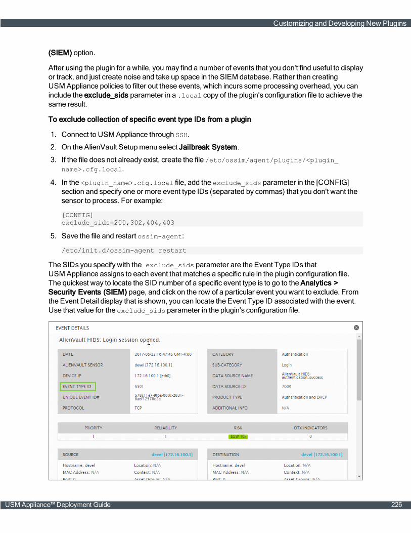
(SIEM) option.
After using the plugin for a while, youmay find a number of events that you don't find useful to displayor track, and just create noise and take up space in the SIEM database. Rather than creatingUSM Appliance policies to filter out these events, which incurs some processing overhead, you caninclude the exclude_sids parameter in a .local copy of the plugin's configuration file to achieve thesame result.
To exclude collection of specific event type IDs from a plugin
1. Connect to USM Appliance through SSH.
2. On the AlienVault Setupmenu select Jailbreak System.
3. If the file does not already exist, create the file /etc/ossim/agent/plugins/<plugin_name>.cfg.local.
4. In the <plugin_name>.cfg.local file, add the exclude_sids parameter in the [CONFIG]section and specify one or more event type IDs (separated by commas) that you don't want thesensor to process. For example:
[CONFIG]exclude_sids=200,302,404,403
5. Save the file and restart ossim-agent:
/etc/init.d/ossim-agent restart
The SIDs you specify with the exclude_sids parameter are the Event Type IDs thatUSM Appliance assigns to each event that matches a specific rule in the plugin configuration file.The quickest way to locate the SID number of a specific event type is to go to the Analytics >Security Events (SIEM) page, and click on the row of a particular event you want to exclude. Fromthe Event Detail display that is shown, you can locate the Event Type ID associated with the event.Use that value for the exclude_sids parameter in the plugin's configuration file.
Customizing and Developing New Plugins
USM Appliance™ Deployment Guide 226
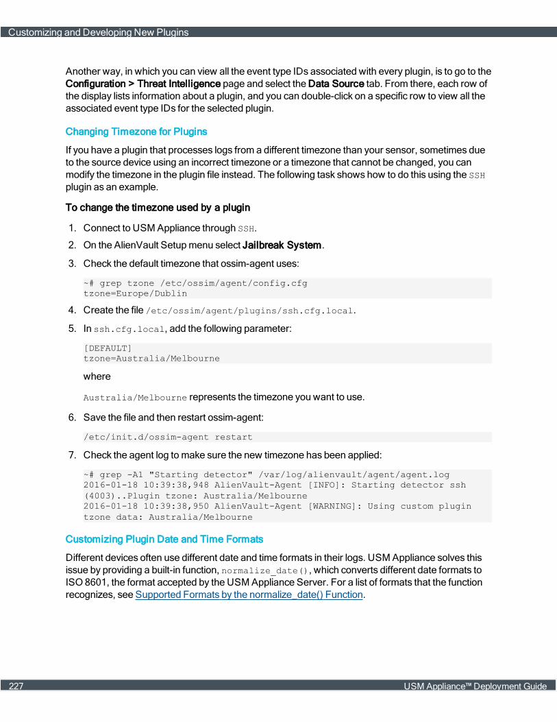
Another way, in which you can view all the event type IDs associated with every plugin, is to go to theConfiguration > Threat Intelligence page and select the Data Source tab. From there, each row ofthe display lists information about a plugin, and you can double-click on a specific row to view all theassociated event type IDs for the selected plugin.
Changing Timezone for Plugins
If you have a plugin that processes logs from a different timezone than your sensor, sometimes dueto the source device using an incorrect timezone or a timezone that cannot be changed, you canmodify the timezone in the plugin file instead. The following task shows how to do this using the SSHplugin as an example.
To change the timezone used by a plugin
1. Connect to USM Appliance through SSH.
2. On the AlienVault Setupmenu select Jailbreak System.
3. Check the default timezone that ossim-agent uses:
~# grep tzone /etc/ossim/agent/config.cfgtzone=Europe/Dublin
4. Create the file /etc/ossim/agent/plugins/ssh.cfg.local.
5. In ssh.cfg.local, add the following parameter:
[DEFAULT]tzone=Australia/Melbourne
where
Australia/Melbourne represents the timezone you want to use.
6. Save the file and then restart ossim-agent:
/etc/init.d/ossim-agent restart
7. Check the agent log tomake sure the new timezone has been applied:
~# grep -A1 "Starting detector" /var/log/alienvault/agent/agent.log2016-01-18 10:39:38,948 AlienVault-Agent [INFO]: Starting detector ssh(4003)..Plugin tzone: Australia/Melbourne2016-01-18 10:39:38,950 AlienVault-Agent [WARNING]: Using custom plugintzone data: Australia/Melbourne
Customizing Plugin Date and Time Formats
Different devices often use different date and time formats in their logs. USMAppliance solves thisissue by providing a built-in function, normalize_date(), which converts different date formats toISO8601, the format accepted by the USMAppliance Server. For a list of formats that the functionrecognizes, see Supported Formats by the normalize_date() Function.
Customizing and Developing New Plugins
227 USM Appliance™ Deployment Guide
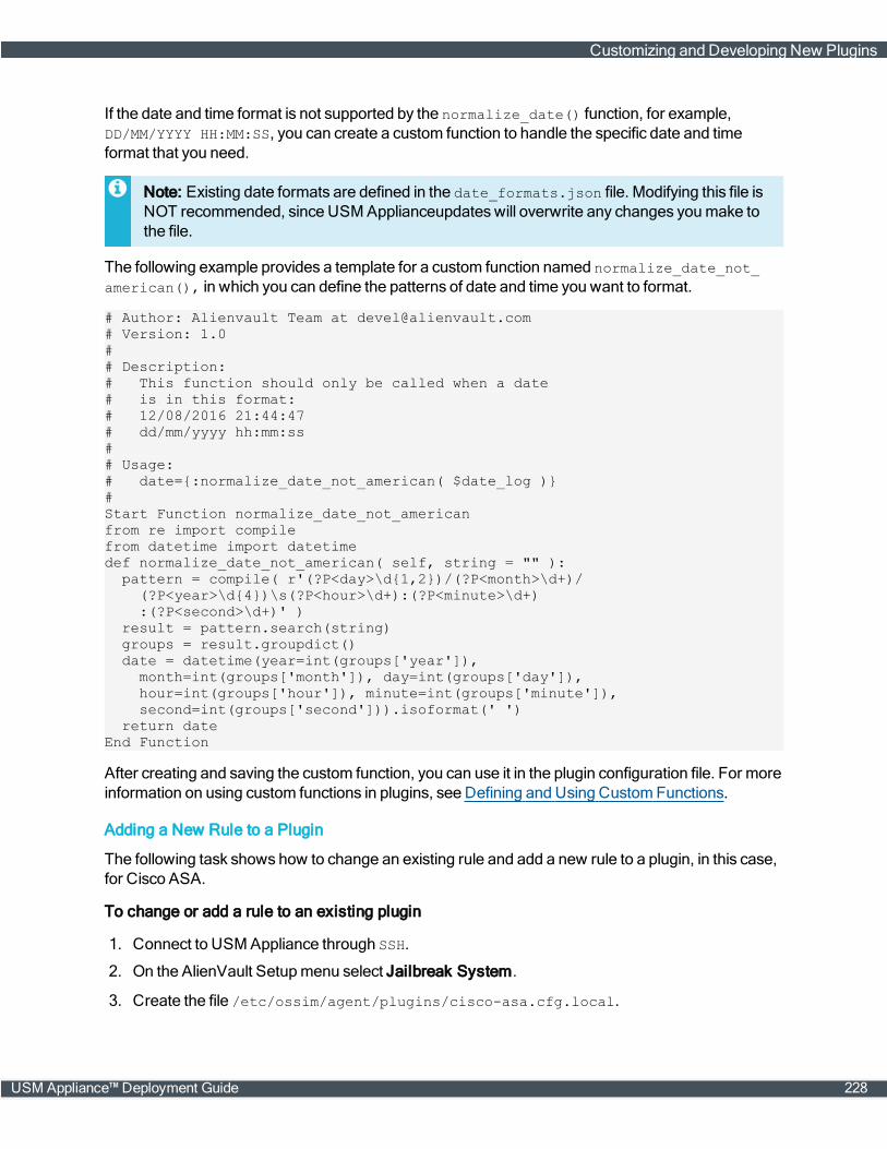
If the date and time format is not supported by the normalize_date() function, for example,DD/MM/YYYY HH:MM:SS, you can create a custom function to handle the specific date and timeformat that you need.
Note: Existing date formats are defined in the date_formats.json file. Modifying this file isNOT recommended, since USM Applianceupdateswill overwrite any changes youmake tothe file.
The following example provides a template for a custom function named normalize_date_not_american(), in which you can define the patterns of date and time you want to format.
# Author: Alienvault Team at [email protected]# Version: 1.0## Description:# This function should only be called when a date# is in this format:# 12/08/2016 21:44:47# dd/mm/yyyy hh:mm:ss## Usage:# date={:normalize_date_not_american( $date_log )}#Start Function normalize_date_not_americanfrom re import compilefrom datetime import datetimedef normalize_date_not_american( self, string = "" ):
pattern = compile( r'(?P<day>\d{1,2})/(?P<month>\d+)/(?P<year>\d{4})\s(?P<hour>\d+):(?P<minute>\d+):(?P<second>\d+)' )
result = pattern.search(string)groups = result.groupdict()date = datetime(year=int(groups['year']),
month=int(groups['month']), day=int(groups['day']),hour=int(groups['hour']), minute=int(groups['minute']),second=int(groups['second'])).isoformat(' ')
return dateEnd Function
After creating and saving the custom function, you can use it in the plugin configuration file. For moreinformation on using custom functions in plugins, see Defining and Using CustomFunctions.
Adding a New Rule to a Plugin
The following task shows how to change an existing rule and add a new rule to a plugin, in this case,for Cisco ASA.
To change or add a rule to an existing plugin
1. Connect to USM Appliance through SSH.
2. On the AlienVault Setupmenu select Jailbreak System.
3. Create the file /etc/ossim/agent/plugins/cisco-asa.cfg.local.
Customizing and Developing New Plugins
USM Appliance™ Deployment Guide 228
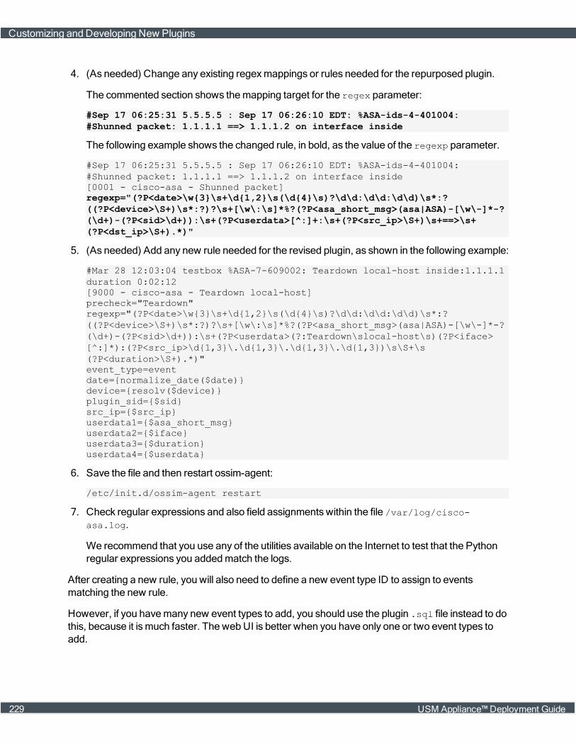
4. (As needed) Change any existing regexmappings or rules needed for the repurposed plugin.
The commented section shows themapping target for the regex parameter:
#Sep 17 06:25:31 5.5.5.5 : Sep 17 06:26:10 EDT: %ASA-ids-4-401004:#Shunned packet: 1.1.1.1 ==> 1.1.1.2 on interface inside
The following example shows the changed rule, in bold, as the value of the regexp parameter.
#Sep 17 06:25:31 5.5.5.5 : Sep 17 06:26:10 EDT: %ASA-ids-4-401004:#Shunned packet: 1.1.1.1 ==> 1.1.1.2 on interface inside[0001 - cisco-asa - Shunned packet]regexp="(?P<date>\w{3}\s+\d{1,2}\s(\d{4}\s)?\d\d:\d\d:\d\d)\s*:?((?P<device>\S+)\s*:?)?\s+[\w\:\s]*%?(?P<asa_short_msg>(asa|ASA)-[\w\-]*-?(\d+)-(?P<sid>\d+)):\s+(?P<userdata>[^:]+:\s+(?P<src_ip>\S+)\s+==>\s+(?P<dst_ip>\S+).*)"
5. (As needed) Add any new rule needed for the revised plugin, as shown in the following example:
#Mar 28 12:03:04 testbox %ASA-7-609002: Teardown local-host inside:1.1.1.1duration 0:02:12[9000 - cisco-asa - Teardown local-host]precheck="Teardown"regexp="(?P<date>\w{3}\s+\d{1,2}\s(\d{4}\s)?\d\d:\d\d:\d\d)\s*:?((?P<device>\S+)\s*:?)?\s+[\w\:\s]*%?(?P<asa_short_msg>(asa|ASA)-[\w\-]*-?(\d+)-(?P<sid>\d+)):\s+(?P<userdata>(?:Teardown\slocal-host\s)(?P<iface>[^:]*):(?P<src_ip>\d{1,3}\.\d{1,3}\.\d{1,3}\.\d{1,3})\s\S+\s(?P<duration>\S+).*)"event_type=eventdate={normalize_date($date)}device={resolv($device)}plugin_sid={$sid}src_ip={$src_ip}userdata1={$asa_short_msg}userdata2={$iface}userdata3={$duration}userdata4={$userdata}
6. Save the file and then restart ossim-agent:
/etc/init.d/ossim-agent restart
7. Check regular expressions and also field assignments within the file /var/log/cisco-asa.log.
We recommend that you use any of the utilities available on the Internet to test that the Pythonregular expressions you addedmatch the logs.
After creating a new rule, you will also need to define a new event type ID to assign to eventsmatching the new rule.
However, if you havemany new event types to add, you should use the plugin .sql file instead to dothis, because it ismuch faster. The webUI is better when you have only one or two event types toadd.
Customizing and Developing New Plugins
229 USM Appliance™ Deployment Guide
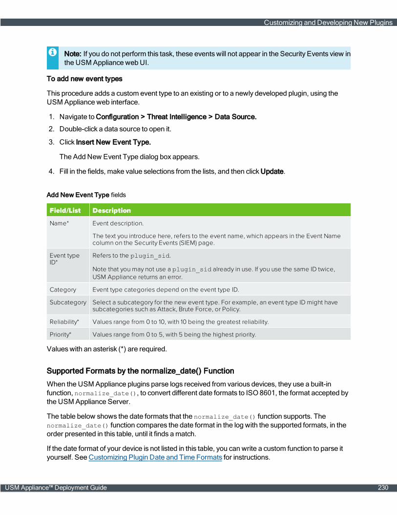
Note: If you do not perform this task, these events will not appear in the Security Events view inthe USM Appliance webUI.
To add new event types
This procedure adds a custom event type to an existing or to a newly developed plugin, using theUSM Appliance web interface.
1. Navigate to Configuration > Threat Intelligence > Data Source.
2. Double-click a data source to open it.
3. Click Insert New Event Type.
The Add New Event Type dialog box appears.
4. Fill in the fields, make value selections from the lists, and then click Update.
Field/List Description
Name* Event description.
The text you introduce here, refers to the event name, which appears in the Event Namecolumn on the Security Events (SIEM) page.
Event typeID*
Refers to the plugin_sid.
Note that you may not use a plugin_sid already in use. If you use the same ID twice,USM Appliance returns an error.
Category Event type categories depend on the event type ID.
Subcategory Select a subcategory for the new event type. For example, an event type ID might havesubcategories such as Attack, Brute Force, or Policy.
Reliability* Values range from 0 to 10, with 10 being the greatest reliability.
Priority* Values range from 0 to 5, with 5 being the highest priority.
Add New Event Type fields
Valueswith an asterisk (*) are required.
Supported Formats by the normalize_date() Function
When the USMAppliance plugins parse logs received from various devices, they use a built-infunction, normalize_date(), to convert different date formats to ISO8601, the format accepted bythe USMAppliance Server.
The table below shows the date formats that the normalize_date() function supports. Thenormalize_date() function compares the date format in the log with the supported formats, in theorder presented in this table, until it finds amatch.
If the date format of your device is not listed in this table, you can write a custom function to parse ityourself. See Customizing Plugin Date and Time Formats for instructions.
Customizing and Developing New Plugins
USM Appliance™ Deployment Guide 230
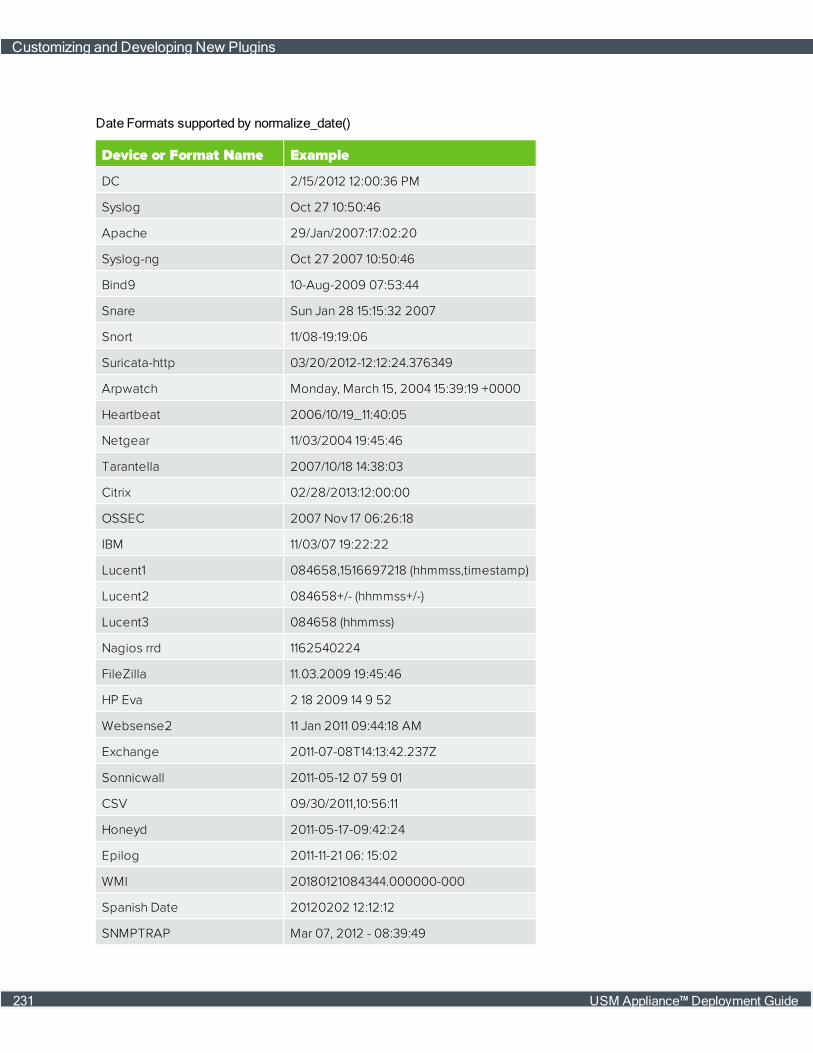
Device or Format Name Example
DC 2/15/2012 12:00:36 PM
Syslog Oct 27 10:50:46
Apache 29/Jan/2007:17:02:20
Syslog-ng Oct 27 2007 10:50:46
Bind9 10-Aug-2009 07:53:44
Snare Sun Jan 28 15:15:32 2007
Snort 11/08-19:19:06
Suricata-http 03/20/2012-12:12:24.376349
Arpwatch Monday, March 15, 2004 15:39:19 +0000
Heartbeat 2006/10/19_11:40:05
Netgear 11/03/2004 19:45:46
Tarantella 2007/10/18 14:38:03
Citrix 02/28/2013:12:00:00
OSSEC 2007 Nov 17 06:26:18
IBM 11/03/07 19:22:22
Lucent1 084658,1516697218 (hhmmss,timestamp)
Lucent2 084658+/- (hhmmss+/-)
Lucent3 084658 (hhmmss)
Nagios rrd 1162540224
FileZilla 11.03.2009 19:45:46
HP Eva 2 18 2009 14 9 52
Websense2 11 Jan 2011 09:44:18 AM
Exchange 2011-07-08T14:13:42.237Z
Sonnicwall 2011-05-12 07 59 01
CSV 09/30/2011,10:56:11
Honeyd 2011-05-17-09:42:24
Epilog 2011-11-21 06: 15:02
WMI 20180121084344.000000-000
Spanish Date 20120202 12:12:12
SNMPTRAP Mar 07, 2012 - 08:39:49
Date Formats supported by normalize_date()
Customizing and Developing New Plugins
231 USM Appliance™ Deployment Guide
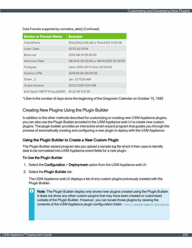
Device or Format Name Example
CheckPoint 1Feb2012;0:05:58 or 1Feb2012 0:05:58
Lilian* Date 11270 02:00:16
Bluecoat 2015-08-14 09:30:00
American Date 08/14/15 09:30:00 or 08/14/2015 09:30:00
Fortigate date=2015-03-17 time=22:03:55
Sophos UTM 2014:09:06-00:00:06
Snare_2 Jan. 22 11:20 AM
Aruba-airwave 01/22/2018 11:20 AM
Anti-Spam SMTP Proxy (ASSP) 01-22-18 11:21:35
Date Formats supported by normalize_date() (Continued)
*Lilian is the number of days since the beginning of the Gregorian Calendar onOctober 15, 1582
Creating NewPlugins Using the Plugin Builder
In addition to the other methods described for customizing or creating new USM Appliance plugins,you can also use the Plugin Builder provided in the USM Appliance webUI to create new customplugins. The plugin builder provides an interactive smart wizard program that guides you through theprocess of automatically creating and configuring a new plugin to deploy with the USM Appliance.
Using the Plugin Builder to Create a New Custom Plugin
The Plugin Builder wizard program lets you upload a sample log file which it then uses to identifydata to be normalized into USM Appliance event fields for a new plugin.
To Use the Plugin Builder
1. Select the Configuration > Deployment option from the USM Appliance webUI.
2. Select the Plugin Builder tab.
The USMAppliance webUI displays a list of any custom plugins previously created with thePlugin Builder.
Note: The Plugin Builder display only shows new plugins created using the Plugin Builder.It does not show any other custom plugins that may have been created or customizedoutside of the Plugin Builder. However, you can locate those plugins by viewing thecontents of the USMAppliance plugin configuration folder: /etc/ossim/agent/plugins.
Customizing and Developing New Plugins
USM Appliance™ Deployment Guide 232

You can also view and enable the custom plugins by establishing an SSH connection tothe AlienVault Console and selecting the Configure Sensor > Configure data sourceplugin option from the AlienVault Setupmenu.
3. Click the Add New Plugin button.
The USMAppliance webUI displays the first step of the Plugin Builder wizard. You areprompted to select a sample log file the Plugin Builder will use to identify data that can benormalized into USMAppliance event fields.
4. Click the Browse button to navigate to the location of the sample log file you want to use toidentify possible event field mapping.
After you choose a log file, the Plugin Builder determineswhether it can upload the file for eventfield mapping and displays a green checkmark if successful.
5. Click Next.
The Plugin Builder advances to step 2 in which you are prompted to enter information about thesource of the log file.
Customizing and Developing New Plugins
233 USM Appliance™ Deployment Guide

Note: Vendor andModel entriesmay not contain spaces or special characters. Only theplugin ID is included in the plugin configuration filename. Vendor, model, and versioninformation is included into the plugin file header.
6. For the Product Type field, select the product type from options displayed in the popup list. (Thecategories list match the USMAppliance SIEM taxonomy.When you have finished the PluginProperties entries, click Next.
The Plugin Builder now displays the initial mapping of log file entries to USMAppliance eventfields for specific named event rules.
Customizing and Developing New Plugins
USM Appliance™ Deployment Guide 234

The top portion of the display shows data contained in the sample log file you submitted and thebottom portion displays corresponding event field mapping that the Plugin Builder identified forone or more named event rules.
7. Click the Edit ( ) button.
The Plugin Builder displays a set of fields in which you can edit the name, category (andsubcategory) that will be used in USMAppliance when eventsmatching specific rules will begenerated by the plugin.
In the area below the event property fields, the Edit Tokens section lets you edit or update datatokens assigned or mapped to USMAppliance event fields.You can alsomap additionalunassigned data patterned after the log data and assign those data tokens to new event fields.
l In the Edit Tokens section, clicking on highlighted keywords shows themapping of token datato assigned event fields. The Plugin Builder shows the current tokenmapping in a dialog boxat the bottom of the display. You can adjust the slider at the bottom to change the tokenmapping and change other attributes of the event field mapping.
l Clicking on non-highlighted token data in the upper portion of the display lets you createadditional log data to event field mappings in the dialog box shown at the bottom of thedisplay.
Customizing and Developing New Plugins
235 USM Appliance™ Deployment Guide
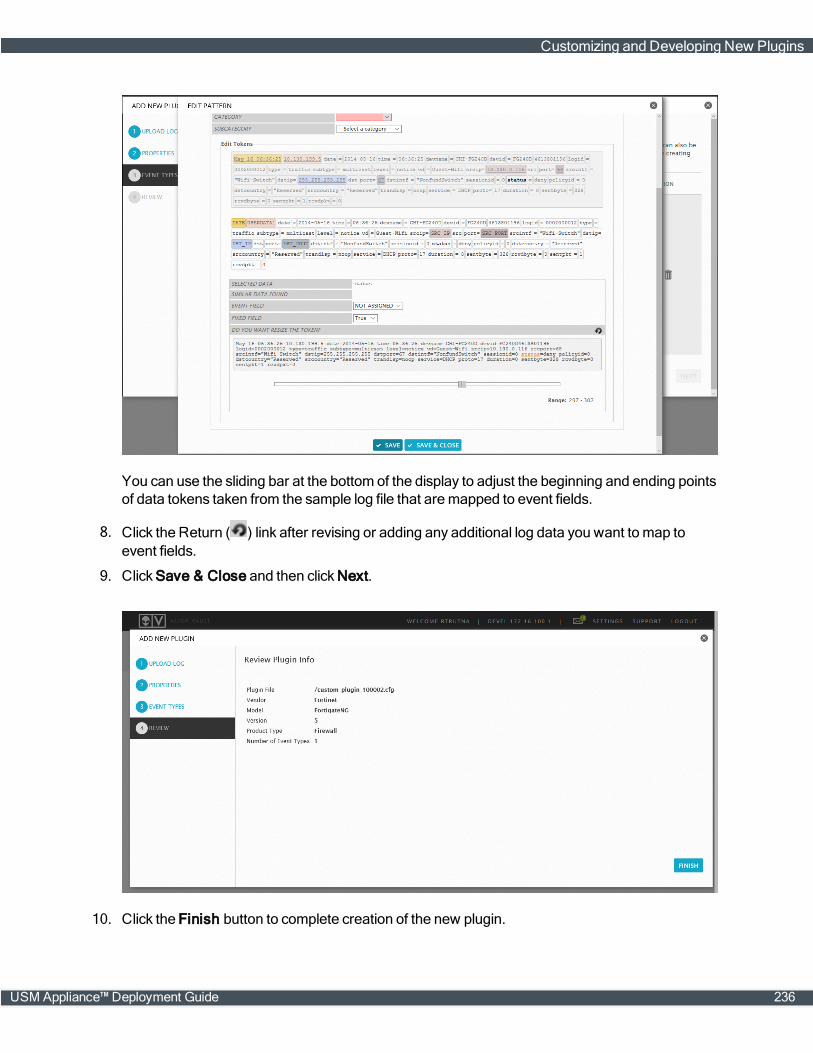
You can use the sliding bar at the bottom of the display to adjust the beginning and ending pointsof data tokens taken from the sample log file that aremapped to event fields.
8. Click the Return ( ) link after revising or adding any additional log data you want to map toevent fields.
9. Click Save & Close and then click Next.
10. Click the Finish button to complete creation of the new plugin.
Customizing and Developing New Plugins
USM Appliance™ Deployment Guide 236
When you click the Finish button, the Plugin builder creates both the configuration (.cfg) fileand the .sql file for the new plugin.
After creating the new plugin, the USMAppliance Plugin Builder wizard returns to themaincustom plugins display page where it shows the new plugin you just created.
Note: The current Plugin Builder does not allow re-editing of custom plugins from the USMAppliance webUI. You can, however, open the plugin configuration file directly with a texteditor andmake additional configuration changes. (Custom plugins are saved in the/etc/alienvault/plugins/custom folder.) You can also delete the existing plugin from thePlugin Builder's tabular list view, delete an existing plugin, and then start over to make a newplugin using the Plugin Builder wizard.
Deploying Custom Plugins
You can use custom plugins created with the Plugin Builder the sameway as all other plugins, byenabling the plugin for individual assets or on a USMAppliance sensor. After creating a new customplugin, the plugin configuration file is saved to the USM Appliance Server (for USM Appliance All-in-One) and also distributed to all configured remote or external sensors. The plugin .sql file isautomatically applied to the USM Appliance Server database. There is no need to copy and run theplugin .sql on external sensors, because they do not have a separate database.
Note: Export or manual copying of plugin .cfg configuration and .sql files is only necessary ifyou want to deploy a new custom plugin to other USM Appliance installations deployed in yourenvironment. Exporting a new custom plugin only exports the plugin .cfg configuration file.So, you will still need tomanually download the plugin .sql file and apply it to the databasesassociated with any other USM ApplianceServer installations you have deployed in yourenvironment.
Developing NewPlugins from Scratch
This section provides an overview of the process you can follow to create a new plugin, from scratch,directly editing and updating the plugin configuration (cfg) and .sql files needed to collect andnormalize events from specific data sources.
Process of Creating a New Plugin
The following procedure details high level steps in the process of creating a new USM Applianceplugin:
1. Create a <filename>.cfg file for the new plugin. Youmaywant to make a copy of an existing.cfg file that is similar to the type of plugin you want to create, to save time.
2. Specify a unique plugin ID (9001 and above) for the plugin and also specify the location of thelog file the plugin will read from. The range of values available for user-defined plugins is 9001 to2147483647, except for the following values, which are also reserved:
Customizing and Developing New Plugins
237 USM Appliance™ Deployment Guide

90003, 90005, 90007, 90008, 10002, 12001, 19004, 19005, 19006, 20505
3. Create event rules using regular expressions tomatch events coming in from a source log file.
4. Create the .sql file that specifies the data written to the SIEM database for all events/rules fieldmapping of extracted data. Youmaywant to make a copy of an existing .sql file that is similar tothe new plugin you want to create, and change the fields to describe events defined in the newplugin.
5. Activate the plugin.
6. Import your .sql file to the SIEM database using the following command:
cat <plugin_name>.sql | ossim-db
7. Test the plugin using the USM Appliance webUI to see if events are being detected
Plugin Design Best Practices
AlienVault offers the following recommendations for developing a new or custom plugin:
l Use a log sample as large as possible to identify events and data patterns. This helps to ensurethat a sufficient number of data variations have been accounted for.
l Extract data from the log by issuing the command, grep -v sequentially until nomore data arereturned.
l Identify all of the values in the log data that may be included in an event.
l Discard any repeated log data.
l Look for data patterns as a way to group them into categories. One organizing principle might, forexample, be having the same data field distribution.
l USM Appliance identifies individual events using a plugin_sid, consisting of a serial number.For this reason, youmay find that you need to add a translation table section to associatecaptured data log fields to plugin_sids. (See Creating a Plugin Configuration File forinformation.)
l Estimate the frequencywith which any event type would be generated from the log by countingthe number of times each log line repeats:
grep <log_line> <logFile> | wc -l
l If you havemultiple similar log lines, evaluate whether it makes sense to apply a single rule toeach, thereby creating two or more unique events, or whether you should create one rule thatdeals with a group of similar log lines and only creates a single event.
In the latter example, you run the risk of making a rule too complex to be effective, because of thenumber of matches needed.
l Only capture the fields that will be used for correlation later on.
l Youmay find that you need to create amore generic rule to capture any events that remain afterspecific rules have all been applied.
Customizing and Developing New Plugins
USM Appliance™ Deployment Guide 238
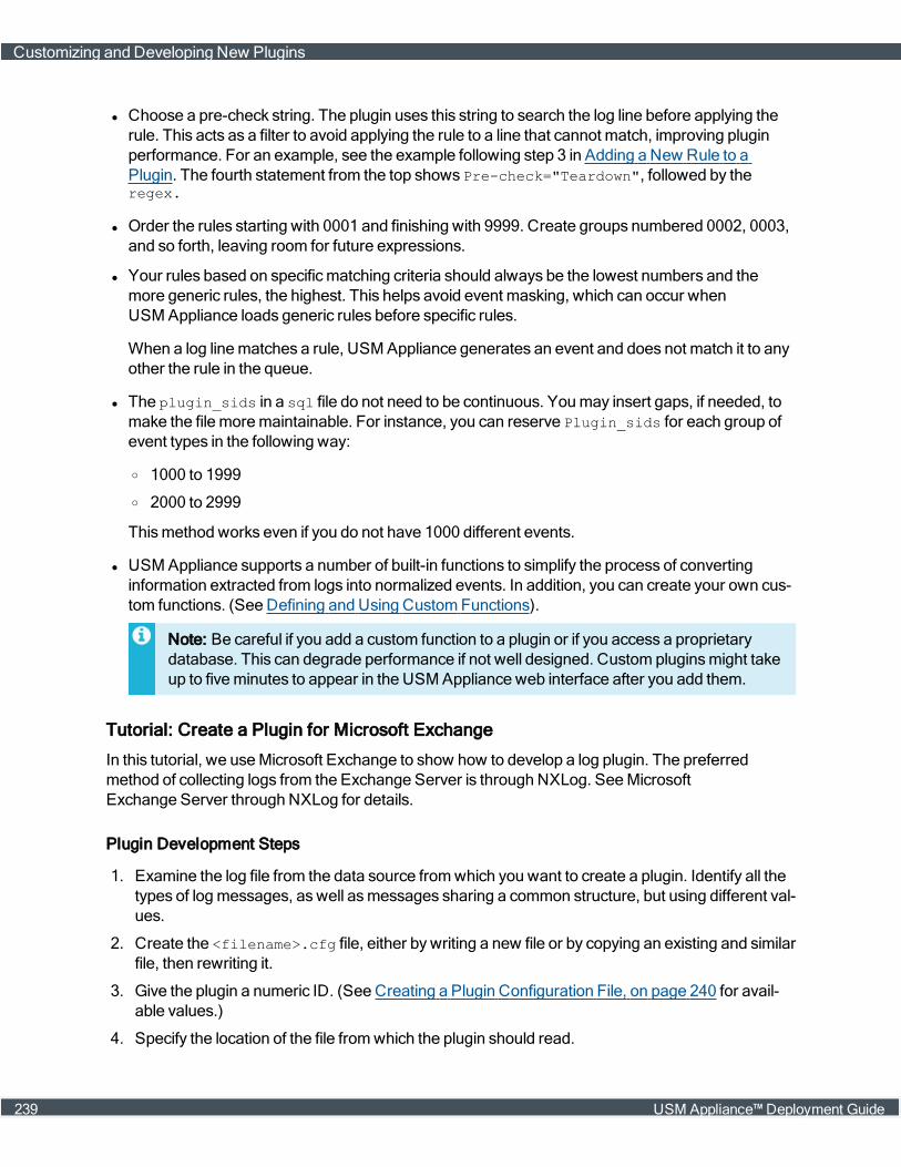
l Choose a pre-check string. The plugin uses this string to search the log line before applying therule. This acts as a filter to avoid applying the rule to a line that cannot match, improving pluginperformance. For an example, see the example following step 3 in Adding a New Rule to aPlugin. The fourth statement from the top shows Pre-check="Teardown", followed by theregex.
l Order the rules starting with 0001 and finishing with 9999. Create groups numbered 0002, 0003,and so forth, leaving room for future expressions.
l Your rules based on specificmatching criteria should always be the lowest numbers and themore generic rules, the highest. This helps avoid event masking, which can occur whenUSM Appliance loads generic rules before specific rules.
When a log linematches a rule, USM Appliance generates an event and does not match it to anyother the rule in the queue.
l The plugin_sids in a sql file do not need to be continuous. Youmay insert gaps, if needed, tomake the file moremaintainable. For instance, you can reserve Plugin_sids for each group ofevent types in the following way:
o 1000 to 1999
o 2000 to 2999
Thismethod works even if you do not have 1000 different events.
l USM Appliance supports a number of built-in functions to simplify the process of convertinginformation extracted from logs into normalized events. In addition, you can create your own cus-tom functions. (See Defining and Using CustomFunctions).
l Note: Be careful if you add a custom function to a plugin or if you access a proprietarydatabase. This can degrade performance if not well designed. Custom pluginsmight takeup to fiveminutes to appear in the USM Appliance web interface after you add them.
Tutorial: Create a Plugin for Microsoft Exchange
In this tutorial, we useMicrosoft Exchange to show how to develop a log plugin. The preferredmethod of collecting logs from the Exchange Server is through NXLog. SeeMicrosoftExchange Server through NXLog for details.
Plugin Development Steps
1. Examine the log file from the data source fromwhich you want to create a plugin. Identify all thetypes of logmessages, aswell asmessages sharing a common structure, but using different val-ues.
2. Create the <filename>.cfg file, either bywriting a new file or by copying an existing and similarfile, then rewriting it.
3. Give the plugin a numeric ID. (See Creating a Plugin Configuration File, on page 240 for avail-able values.)
4. Specify the location of the file fromwhich the plugin should read.
Customizing and Developing New Plugins
239 USM Appliance™ Deployment Guide
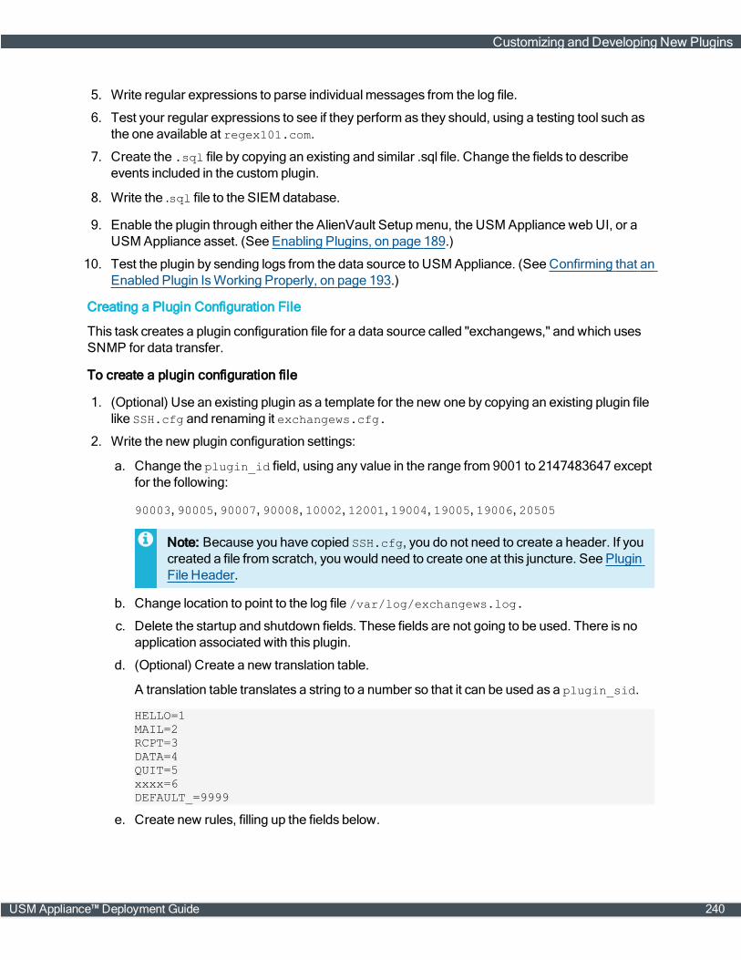
5. Write regular expressions to parse individualmessages from the log file.
6. Test your regular expressions to see if they perform as they should, using a testing tool such asthe one available at regex101.com.
7. Create the .sql file by copying an existing and similar .sql file. Change the fields to describeevents included in the custom plugin.
8. Write the .sql file to the SIEM database.
9. Enable the plugin through either the AlienVault Setupmenu, the USM Appliance webUI, or aUSM Appliance asset. (See Enabling Plugins, on page 189.)
10. Test the plugin by sending logs from the data source to USM Appliance. (See Confirming that anEnabled Plugin IsWorking Properly, on page 193.)
Creating a Plugin Configuration File
This task creates a plugin configuration file for a data source called "exchangews," and which usesSNMP for data transfer.
To create a plugin configuration file
1. (Optional) Use an existing plugin as a template for the new one by copying an existing plugin filelike SSH.cfg and renaming it exchangews.cfg.
2. Write the new plugin configuration settings:
a. Change the plugin_id field, using any value in the range from 9001 to 2147483647 exceptfor the following:
90003, 90005, 90007, 90008, 10002, 12001, 19004, 19005, 19006, 20505
Note: Because you have copied SSH.cfg, you do not need to create a header. If youcreated a file from scratch, you would need to create one at this juncture. See PluginFile Header.
b. Change location to point to the log file /var/log/exchangews.log.
c. Delete the startup and shutdown fields. These fields are not going to be used. There is noapplication associated with this plugin.
d. (Optional) Create a new translation table.
A translation table translates a string to a number so that it can be used as a plugin_sid.
HELLO=1MAIL=2RCPT=3DATA=4QUIT=5xxxx=6DEFAULT_=9999
e. Create new rules, filling up the fields below.
Customizing and Developing New Plugins
USM Appliance™ Deployment Guide 240

f. Create two regular expressions to parse the data, because there are two different formats inthe log file.[exchangews - Generic rule]#2011-10-09 05:00:15 1.1.1.1 36A42160 SMTPSVC1 MEE-PDC 192.168.1.2 0HELO - +36A42160 250 0 48 13 0 SMTP - - - -#2011-10-09 05:00:16 1.1.1.1 36A42160 SMTPSVC1 MEE-PDC 192.168.1.2 0MAIL - +FROM:+<[email protected]> 250 0 57 45 0 SMTP - - - -event_type=eventregexp="(?P<date>\d{4}-\d{2}-\d{2}\s\d{2}:\d{2}:\d{2})\s(?P<src_ip>\IPV4)\s(?P<userdata2>\S+)\s(?P<hostname>\S+)\s(?P<userdata3>\S+)\s(?P<dst_IP>\IPV4)\s\d\s(?P<type>\w+)"date={normalize_date($date)}plugin_sid={translate($type)}dst_ip={resolv($dst_ip)}src_ip={resolv($src_ip)}hostname={$hostname}userdata2={$userdata2}userdata3={$userdata3}[exchangews = Generic rule 2 NCSA Format]#1.1.1.10 - 1.1.1.9 [11/Oct/2011:13:16:40 -0600] "HELO -?+1.1.1.9 SMTP"250 46#1.1.1.10 - 1.1.1.9 [11/Oct/2011:13:16:41 -0600] "MAIL-?+FROM:+<[email protected]> SMTP" 250 46event_type=eventregexp="(?P<src_ip>\IPV4)\s-\s(?P<dst_ip>\S+)\s\[(?P<date>\d\d\/\w{3}\/\d{4}:\d\d:\d\d:\d\d)\s-\d{4}\]\s\"(?P<type>\w+)"date={normalize_date($date)}plugin_sid={translate($type)}dst_ip={resolv($dst_ip)}src_ip={resolv($src_ip)}
g. Check regular expressionswith logs inside the file /var/log/exchangews.log.
There are several utilities on the Internet to test regular expressionswritten in Python. It isrecommended to use one of these utilities to check that the created regular expressionsmatch the logs.
Note: The location parameter is limited to 100 files.
Creating a Plugin .sql File
The following example shows the plugin .sql file corresponding to the plugin configuration fileexample.
INSERT INTO plugin (id, type, name, description) VALUES (9001, 1,'exchangews', 'Exchange E-mail Web server');INSERT INTO plugin_sid (plugin_id, sid, category_id, class_id, name, priority,reliability) VALUES (9001, 1, NULL, NULL, 'exchangews: HELO' ,3, 2);INSERT INTO plugin_sid (plugin_id, sid, category_id, class_id, name, priority,reliability) VALUES (9001, 9999, NULL, NULL, 'exchangews: Generic exchangeevent' ,3, 2);
Updating the SIEM Database
USM Appliancemust store all the plugin IDs and event types in its database before it can store any
Customizing and Developing New Plugins
241 USM Appliance™ Deployment Guide
events. For this reason, if you develop a new plugin and you don't first update the database with thatdata, the USM Appliance Server drops those events, even though the plugin is working correctly.
To update the SIEM database
1. Write the changes to the SIEM database:
cat exchangews.sql | ossim-db
2. Apply changes in the SIEM:
ossim-server restart
Customizing and Developing New Plugins
USM Appliance™ Deployment Guide 242
Update Process
This section covers the following subtopics:
About the USM Appliance Updates 244
Updating USM ApplianceOnline 245
Updating USM ApplianceOffline 248
USM Appliance™ Deployment Guide 243
About the USM Appliance Updates
AlienVault strongly recommends that you keep the USM Appliance installation up-to-date and on thesame version if you have deployedmultiple USM Appliance instances.While USM Appliance arebackward-compatible, the difference between versions can cause you tomiss security events.Follow the order below while updating different USM Appliance components:
1. USM Appliance Logger (if any)
2. USM Appliance Server or USMAppliance All-in-One
3. USM Appliance Sensor
By following this order, you ensure that the USM Appliance Server/All-in-One correctly processesany data received from the USM Appliance Sensor, should the update contain any formattingchanges.
USM Appliance Product Releases
AlienVault delivers patches containing security updates and defect fixes to existing releases.
AlienVault communicates any new major releases before general availability.
To find out the details of each product release, check the New Update: AlienVault <version> hasbeen releasedmessages in theMessage Center.
AlienVault Labs Threat Intelligence Updates
AlienVault Labs delivers threat intelligence updates to the USM Appliance platform every week.These updates typically include:
l Correlation rules
l Cross-correlation rules
l Network IDS signatures
l Host IDS signatures
l Vulnerability threat database
l Reports
Note: Since the threat intelligence update refreshes the vulnerability threat database used byvulnerability scans, it will not finish if any scan job is running.
To find out the details of each threat intelligence update, checkMessage Center for the AlienVaultLabs Threat Intelligence Update Summarymessages.
About the USM Appliance Updates
244 USM Appliance™ Deployment Guide
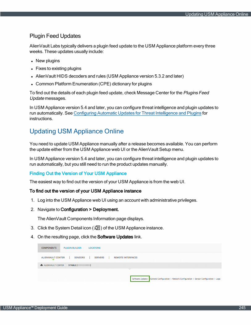
Plugin Feed Updates
AlienVault Labs typically delivers a plugin feed update to the USM Appliance platform every threeweeks. These updates usually include:
l New plugins
l Fixes to existing plugins
l AlienVault HIDS decoders and rules (USM Appliance version 5.3.2 and later)
l Common PlatformEnumeration (CPE) dictionary for plugins
To find out the details of each plugin feed update, checkMessage Center for the Plugins FeedUpdatemessages.
In USM Appliance version 5.4 and later, you can configure threat intelligence and plugin updates torun automatically. See Configuring Automatic Updates for Threat Intelligence and Plugins forinstructions.
Updating USM Appliance Online
You need to update USM Appliancemanually after a release becomes available. You can performthe update either from the USM Appliance webUI or the AlienVault Setupmenu.
In USM Appliance version 5.4 and later, you can configure threat intelligence and plugin updates torun automatically, but you still need to run the product updatesmanually.
Finding Out the Version of Your USM Appliance
The easiest way to find out the version of your USM Appliance is from the webUI.
To find out the version of your USM Appliance instance
1. Log into the USM Appliance webUI using an account with administrative privileges.
2. Navigate to Configuration > Deployment.
The AlienVault Components Information page displays.
3. Click the SystemDetail icon ( ) of the USM Appliance instance.
4. On the resulting page, click the Software Updates link.
Updating USM ApplianceOnline
USM Appliance™ Deployment Guide 245

The AlienVault Package Information page displays
The pages shows the current version of your system, threat intelligence, and plugins, as well asthe date and time of your latest system update.
Note: If your USMAppliance is already on the latest version, the list of AlienVaultpackageswill be empty. You will see "SystemUpdated" instead. If you are not on the latestversion, however, the webUI displays the list of packages you can update to.
Updating from the Web UI
You can update USM Appliance from the USM Appliance webUI or the AlienVault Setupmenu.AlienVault recommends the webUI for its ease of use.
To update USM Appliance from the web UI
1. Log into the USM Appliance webUI using an account with administrative privileges.
2. Navigate to Configuration > Deployment.
The AlienVault Components Information page displays.
3. Check the New Updates column for the USM Appliance component of interest. If an update isavailable, a downward-pointing arrow icon displays:
4. To retrieve information about the update, click the arrow.
5. Review the target update packages.
6. Update the software:
Updating USM ApplianceOnline
246 USM Appliance™ Deployment Guide
l To update threat intelligence or plugin feeds, click Update Feed Only.
l To upgrade to a new product release, click Update All.
The process can take several minutes. The system displays a successmessage when theupdate process completeswithout issues.
Updating from the AlienVault Setup Menu
You can also update USM Appliance from the AlienVault Setupmenu. Some updates, especiallythose that require a system restart, must be run from the AlienVault Setupmenu, because thesystem loses connection to the webUI during a restart. AlienVault will specify, in the release notes, ifyou need to run the update from the AlienVault Setupmenu.
To update USM Appliance from the AlienVault Setup menu
1. Log in to USM Appliance through SSH.
The AlienVault Setupmenu appears with System Preferences as the default selection.
2. To update the appliance, press Enter (<OK>).
3. Tab to Update AlienVault System and press Enter.
4. Update the software:
l To update to a new product release, tab to Update System and press Enter.
l To update threat intelligence or plugin feeds only, tab to Update Threat Intelligence andpress Enter.
5. Confirm your selection by pressing Enter.
The process can take several minutes. The system displays a successmessage when theupdate process completeswithout issues.
If you connect to the USM Appliance instance through a console (not using SSH), and a reboot isneeded after an update, the console displays a splash screen after the post message and throughthe boot process. If you wish to see boot messages, you can press the up arrow key to display them,or the down arrow key to return to the splash screen.
Configuring Automatic Updates for Threat Intelligence and Plugins
In USM Appliance version 5.4 and later, you can configure threat intelligence and plugin updates torun at a certain hour every day. USM Appliance will execute the update as it becomes available. Youwill see amessage in theMessage Center to confirm the success or failure of the update.
To configure automatic updates
1. Log into the USM Appliance webUI using an account with administrative privileges.
2. Navigate to Configuration > Administration > Main.
3. Click Automatic Updates.
4. Change Automatically run Plugin updates and Threat Intelligence updates to Yes.
Updating USM ApplianceOnline
USM Appliance™ Deployment Guide 247
5. In Schedule automatic updates to run, select the hour for USM Appliance to check (daily) andrun the update when available.
Note: The schedule is based on the time zone you have configured for the USM Applianceinstance.
Updating USM Appliance Offline
Updating your USM Appliance offline requires use of the following items:
l A USM Appliance ISO image
l A USB drive with a USB 2.0 interface to burn the ISO image
In order to perform an offline update on AlienVault USM Appliance, you first need to download theISO image of the version you desire. For instructions, see Downloading a USM Appliance ISOImage, on page 249.
Then you need to burn the ISO image to a USB drive. For instructions, see Burning theUSM Appliance ISO Image to a USB Drive, on page 249.
Using an ISO image burned to a USB drive is the preferred way to update USMAppliance offline.However, the USMAppliance VMware image does not contain a USB controller, therefore youcannot connect a USB drive to it. For instructions on how to add a USB controller in a virtualmachine, see VMware's knowledge base article about USB support.
If using a USB drive is not an option, you can upload the ISO image to a datastore and then access itthrough a CD or DVD drive. Click the following links for instructions fromVMware documentationrespectively
l Upload ISO Image InstallationMedia for a Guest Operating System
l Add a CD or DVD Drive to a Virtual Machine in the vSphereWebClient
Note: Select "Datastore ISOFile" as the device type and "Connect At Power On" toconnect the device when the virtual machine turns on.
Finally, you can follow the procedure below to update your USM Appliance.
To update the USM Appliance offline
1. Connect to the AlienVault Console through SSH and use your credentials to log in.
The AlienVault Setupmenu displays.
2. Select System Preferences.
3. Select Update AlienVault System.
4. Select Update (Offline).
5. Insert the USB drive into themachine now, or connect the CD/DVD drive with the
Updating USM ApplianceOffline
248 USM Appliance™ Deployment Guide
USM Appliance ISO image, and then press Enter (<OK>).
The update process scans for any connected file system, either USB or CD/DVD, andmounts itautomatically.
Downloading a USM Appliance ISO Image
In order to perform an offline update or software restoration on AlienVault USM Appliance, you firstneed to download the ISO image of the version you desire.
l For offline update downloads, visit https://offlineupdate.alienvault.com/files/.
l For software restoration downloads, visit https://offlineupdate.alienvault.com/images/.
To download the USM Appliance ISO image
1. Go to the corresponding download site based on your need.
2. Enter the license key for the product you try to download.
3. Click Submit.
4. Locate the USM Appliance version you want to download and click the link.
Note: The offline update download file starts with "AlienVault_USM_UPDATE-FOR-64bits." The software restoration download file starts with "USB_Restoration."
5. Verify your download by comparing itsMD5 checksum against the one listed in the md5.txt file,available on the same site.
Next ...
For instructions on offline update, see Updating USM ApplianceOffline.
For instructions on software restoration (factory reset), see Restoring Software on a USM ApplianceHardware.
Burning the USM Appliance ISO Image to a USBDrive
This procedure is a prerequisite to updating USM Appliance offline or restoring the software on ahardware appliance to its factory settings. For details, see Updating USM ApplianceOffline, on page248 or Restoring Software on a USM Appliance Hardware, on page 276.
Important: This process deletes all files stored on the USB device.
The procedure is different based on the operating system you use. Follow the steps accordingly.
Updating USM ApplianceOffline
USM Appliance™ Deployment Guide 249
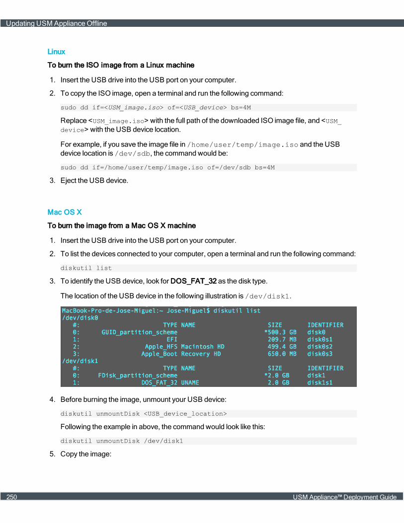
Linux
To burn the ISO image from a Linux machine
1. Insert the USB drive into the USB port on your computer.
2. To copy the ISO image, open a terminal and run the following command:
sudo dd if=<USM_image.iso> of=<USB_device> bs=4M
Replace <USM_image.iso> with the full path of the downloaded ISO image file, and <USM_device> with the USB device location.
For example, if you save the image file in /home/user/temp/image.iso and the USBdevice location is /dev/sdb, the commandwould be:
sudo dd if=/home/user/temp/image.iso of=/dev/sdb bs=4M
3. Eject the USB device.
Mac OS X
To burn the image from a Mac OS X machine
1. Insert the USB drive into the USB port on your computer.
2. To list the devices connected to your computer, open a terminal and run the following command:
diskutil list
3. To identify the USB device, look for DOS_FAT_32 as the disk type.
The location of the USB device in the following illustration is /dev/disk1.
4. Before burning the image, unmount your USB device:
diskutil unmountDisk <USB_device_location>
Following the example in above, the commandwould look like this:
diskutil unmountDisk /dev/disk1
5. Copy the image:
Updating USM ApplianceOffline
250 USM Appliance™ Deployment Guide
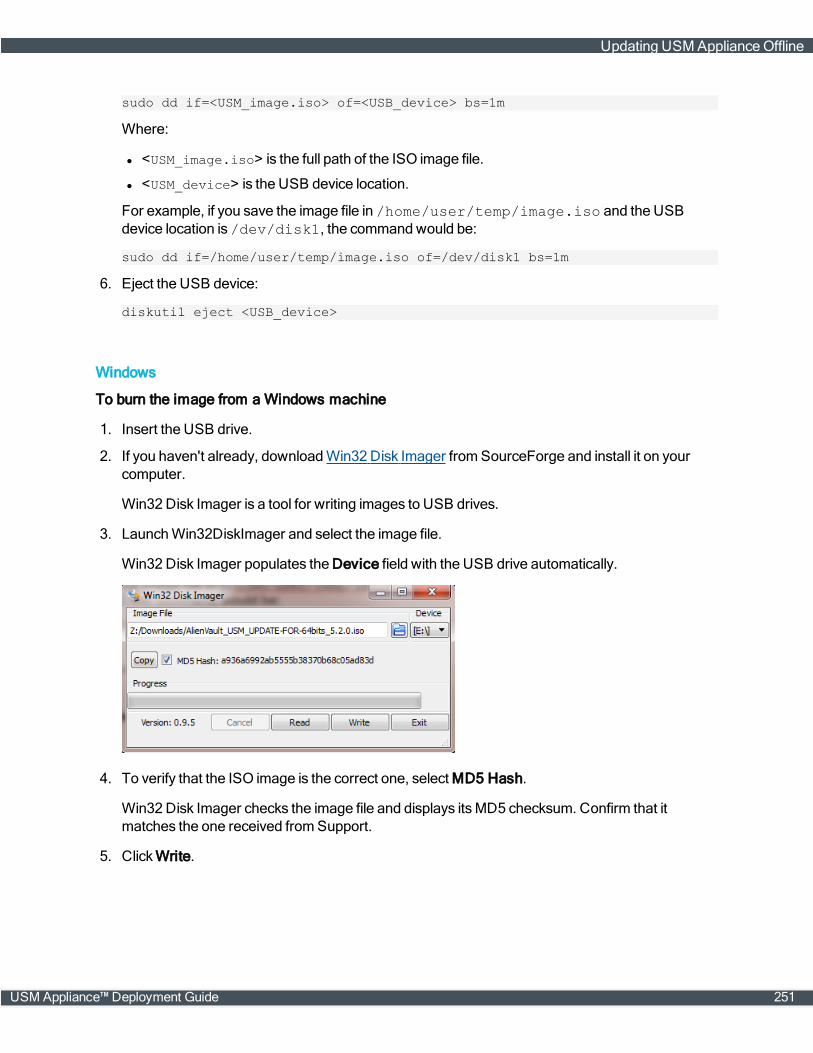
sudo dd if=<USM_image.iso> of=<USB_device> bs=1m
Where:
l <USM_image.iso> is the full path of the ISO image file.
l <USM_device> is the USB device location.
For example, if you save the image file in /home/user/temp/image.iso and the USBdevice location is /dev/disk1, the commandwould be:
sudo dd if=/home/user/temp/image.iso of=/dev/disk1 bs=1m
6. Eject the USB device:
diskutil eject <USB_device>
Windows
To burn the image from a Windows machine
1. Insert the USB drive.
2. If you haven't already, downloadWin32 Disk Imager fromSourceForge and install it on yourcomputer.
Win32 Disk Imager is a tool for writing images to USB drives.
3. LaunchWin32DiskImager and select the image file.
Win32 Disk Imager populates the Device field with the USB drive automatically.
4. To verify that the ISO image is the correct one, select MD5 Hash.
Win32 Disk Imager checks the image file and displays itsMD5 checksum. Confirm that itmatches the one received fromSupport.
5. ClickWrite.
Updating USM ApplianceOffline
USM Appliance™ Deployment Guide 251
Confirmwhile prompted.
6. Exit Win32 Disk Imager after the progress completes.
7. Eject the USB drive.
Updating USM ApplianceOffline
252 USM Appliance™ Deployment Guide
Backup and Restoration
AlienVault USM Appliance does not offer a tool to back up or restore the entire system collectively.However, you can back up or restore your data and system configurations separately. You can alsorestore the USM Appliance hardware appliance to its factory status if needed.
If you need to transfer backup files from one USM Appliance to another, for example, from adefective USM Appliance to its RMA (ReturnMerchandise Authorization) replacement, you can useeither an SFTP client onWindows, such as WinSCP; or the SCP protocol on Linux.
Topics covered in this section includes the following:
Backing Up and Restoring Alarms 254
Backing Up and Restoring Events 256
Backing Up and RestoringMongoDB 259
Backing Up and Restoring NetFlow Data 260
Backing Up and Restoring Raw Logs 263
Backing Up and Restoring SystemConfiguration 266
Migrating Your USM Appliance Deployment 271
Restoring Software on a USM Appliance Hardware 276
USM Appliance™ Deployment Guide 253
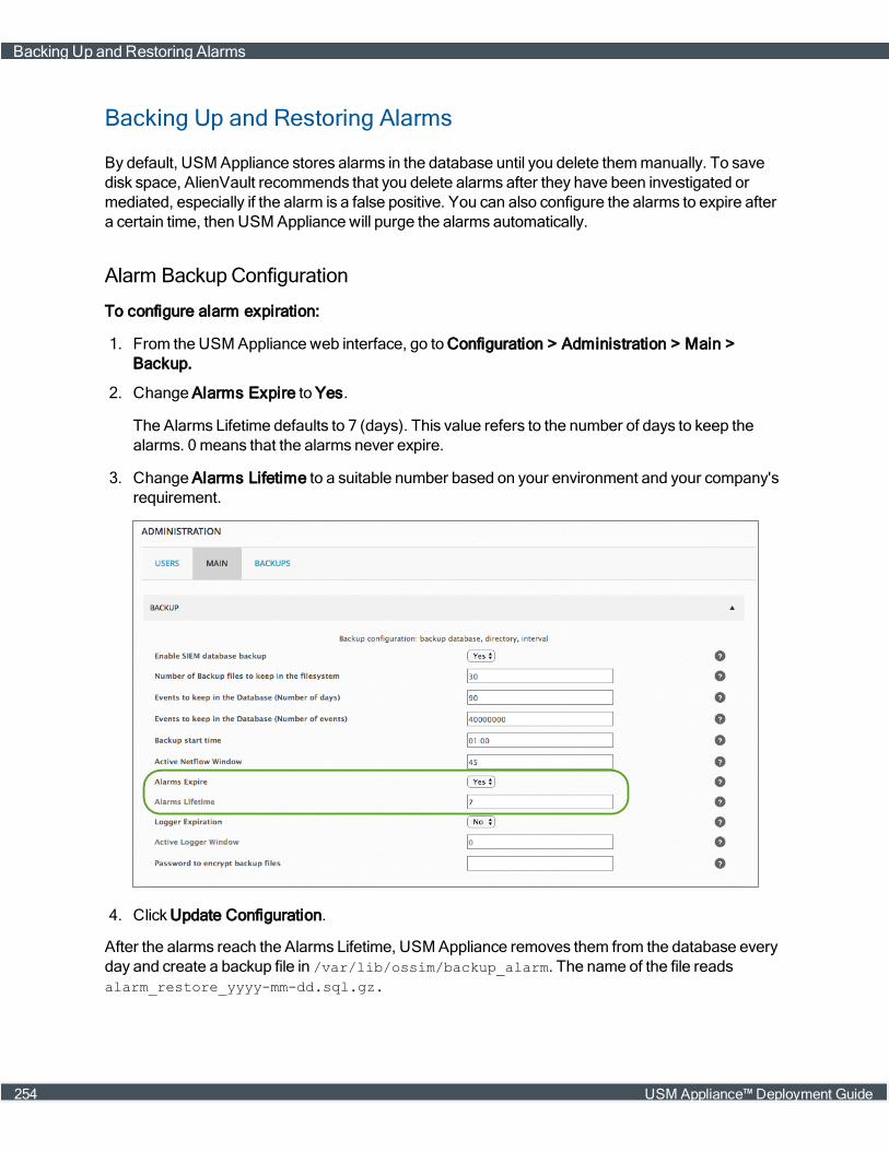
Backing Up and Restoring Alarms
By default, USM Appliance stores alarms in the database until you delete themmanually. To savedisk space, AlienVault recommends that you delete alarms after they have been investigated ormediated, especially if the alarm is a false positive. You can also configure the alarms to expire aftera certain time, then USM Appliance will purge the alarms automatically.
Alarm Backup Configuration
To configure alarm expiration:
1. From the USM Appliance web interface, go to Configuration > Administration > Main >Backup.
2. Change Alarms Expire to Yes.
The Alarms Lifetime defaults to 7 (days). This value refers to the number of days to keep thealarms. 0means that the alarms never expire.
3. Change Alarms Lifetime to a suitable number based on your environment and your company'srequirement.
4. Click Update Configuration.
After the alarms reach the Alarms Lifetime, USM Appliance removes them from the database everyday and create a backup file in /var/lib/ossim/backup_alarm. The name of the file readsalarm_restore_yyyy-mm-dd.sql.gz.
Backing Up and Restoring Alarms
254 USM Appliance™ Deployment Guide
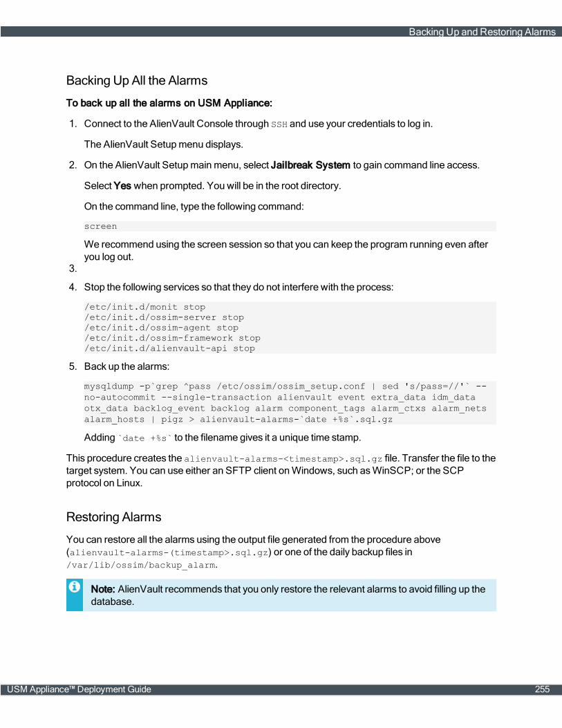
Backing Up All the Alarms
To back up all the alarms on USM Appliance:
1. Connect to the AlienVault Console through SSH and use your credentials to log in.
The AlienVault Setupmenu displays.
2. On the AlienVault Setupmainmenu, select Jailbreak System to gain command line access.
Select Yes when prompted. You will be in the root directory.
3.
On the command line, type the following command:
screen
We recommend using the screen session so that you can keep the program running even afteryou log out.
4. Stop the following services so that they do not interfere with the process:
/etc/init.d/monit stop/etc/init.d/ossim-server stop/etc/init.d/ossim-agent stop/etc/init.d/ossim-framework stop/etc/init.d/alienvault-api stop
5. Back up the alarms:
mysqldump -p`grep ^pass /etc/ossim/ossim_setup.conf | sed 's/pass=//'` --no-autocommit --single-transaction alienvault event extra_data idm_dataotx_data backlog_event backlog alarm component_tags alarm_ctxs alarm_netsalarm_hosts | pigz > alienvault-alarms-`date +%s`.sql.gz
Adding `date +%s` to the filename gives it a unique time stamp.
This procedure creates the alienvault-alarms-<timestamp>.sql.gz file. Transfer the file to thetarget system. You can use either an SFTP client onWindows, such as WinSCP; or the SCPprotocol on Linux.
Restoring Alarms
You can restore all the alarms using the output file generated from the procedure above(alienvault-alarms-(timestamp>.sql.gz) or one of the daily backup files in/var/lib/ossim/backup_alarm.
Note: AlienVault recommends that you only restore the relevant alarms to avoid filling up thedatabase.
Backing Up and Restoring Alarms
USM Appliance™ Deployment Guide 255
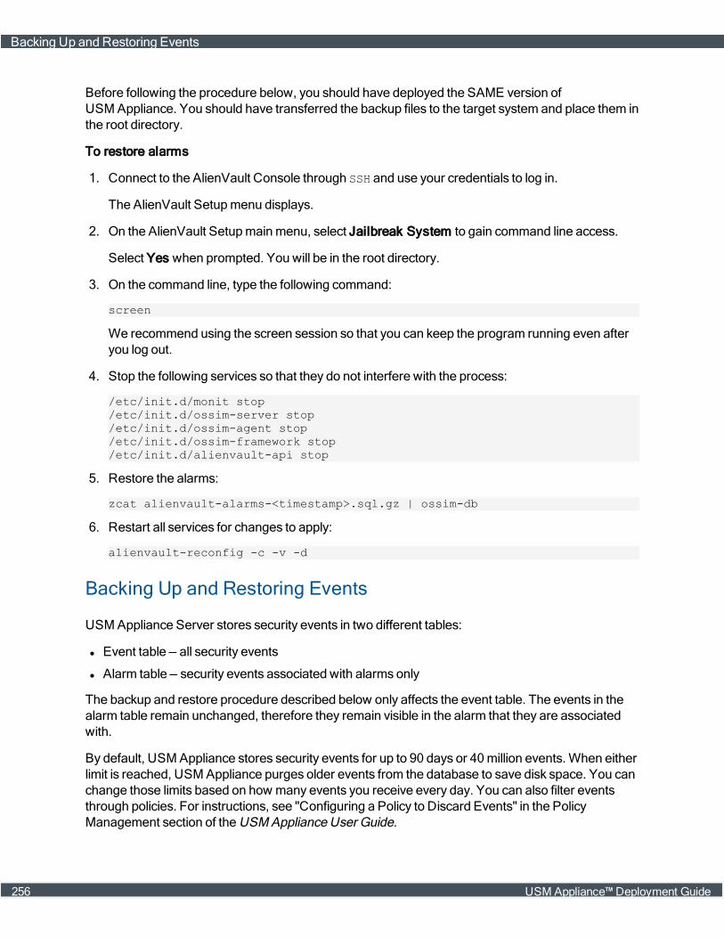
Before following the procedure below, you should have deployed the SAME version ofUSM Appliance. You should have transferred the backup files to the target system and place them inthe root directory.
To restore alarms
1. Connect to the AlienVault Console through SSH and use your credentials to log in.
The AlienVault Setupmenu displays.
2. On the AlienVault Setupmainmenu, select Jailbreak System to gain command line access.
Select Yes when prompted. You will be in the root directory.
3. On the command line, type the following command:
screen
We recommend using the screen session so that you can keep the program running even afteryou log out.
4. Stop the following services so that they do not interfere with the process:
/etc/init.d/monit stop/etc/init.d/ossim-server stop/etc/init.d/ossim-agent stop/etc/init.d/ossim-framework stop/etc/init.d/alienvault-api stop
5. Restore the alarms:
zcat alienvault-alarms-<timestamp>.sql.gz | ossim-db
6. Restart all services for changes to apply:
alienvault-reconfig -c -v -d
Backing Up and Restoring Events
USM Appliance Server stores security events in two different tables:
l Event table — all security events
l Alarm table — security events associated with alarms only
The backup and restore procedure described below only affects the event table. The events in thealarm table remain unchanged, therefore they remain visible in the alarm that they are associatedwith.
By default, USM Appliance stores security events for up to 90 days or 40million events. When eitherlimit is reached, USM Appliance purges older events from the database to save disk space. You canchange those limits based on how many events you receive every day. You can also filter eventsthrough policies. For instructions, see "Configuring a Policy to Discard Events" in the PolicyManagement section of the USM Appliance User Guide.
Backing Up and Restoring Events
256 USM Appliance™ Deployment Guide

Event Backup Configuration
Event backups are enabled by default. In USM Appliance version 5.4, AlienVault added a newparameter, backup_events_min_free_disk_space, to set theminimum free disk space requiredfor event backup to take place. The default is 10%. If the free disk space on the system is less thanthis setting, event backup will not start.
To change any of the default values for event backups:
1. From the USM Appliance web interface, go to Configuration > Administration > Main >Backup.
2. Change the Allowed free disk space for the SIEM backups, if desired.
Available values are 10% and 15%. Default is 10%.
3. Change the Number of Backup files to keep in the filesystem, if desired.
USM Appliance keeps one backup file per day for event backups. Default is 30.
4. Change the number of days to keep events in the database, if desired.
0means that there are no backup for events. Default is 90.
5. Alternatively, change the number of events you want to keep, if desired.
0means that there is no limit to store events in the database. Default is 40,000,000
Important: AlienVault discourages setting either limit to 0 because youmay soon run out ofdisk space.
6. Click Update Configuration.
Backing Up and Restoring Events
USM Appliance™ Deployment Guide 257
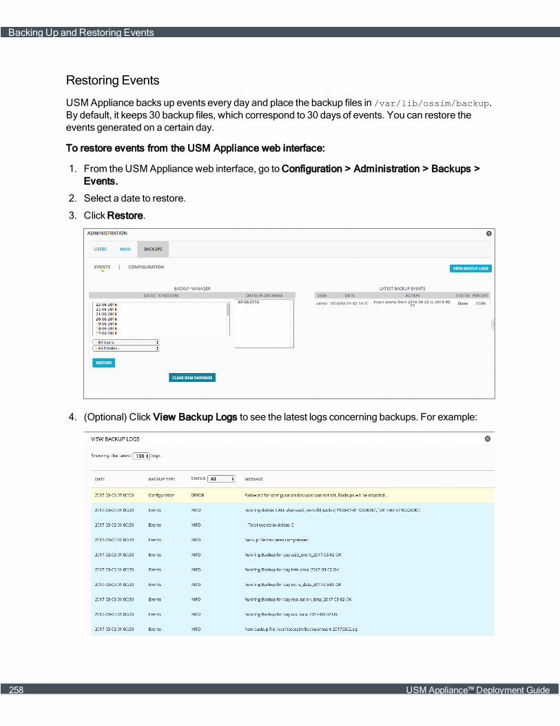
Restoring Events
USM Appliance backs up events every day and place the backup files in /var/lib/ossim/backup.By default, it keeps 30 backup files, which correspond to 30 days of events. You can restore theevents generated on a certain day.
To restore events from the USM Appliance web interface:
1. From the USM Appliance web interface, go to Configuration > Administration > Backups >Events.
2. Select a date to restore.
3. Click Restore.
4. (Optional) Click View Backup Logs to see the latest logs concerning backups. For example:
Backing Up and Restoring Events
258 USM Appliance™ Deployment Guide
Backing Up and Restoring MongoDB
MongoDB is a cross-platform and open-source document-oriented database, a kind of NoSQLdatabase. As a NoSQL database, MongoDB avoids the relational database’s table-based structureto adapt JSON-like documents that have dynamic schemas, which it calls BSON.
Thismakes data integration for certain types of applications faster and easier. MongoDB is built forscalability, high availability, and performance from a single server deployment to large and complexmulti-site infrastructures.
Backing UpMongoDB
To back up MongoDB
1. Connect to the AlienVault Console through SSH and use your credentials to log in.
The AlienVault Setupmenu displays.
2. On the AlienVault Setupmainmenu, select Jailbreak System to gain command line access.
Select Yes when prompted. You will be in the root directory.
3.
On the command line, type the following command:
screen
We recommend using the screen session so that you can keep the program running even afteryou log out.
4. Back up theMongoDB database and create the dump directory:
mongodump --host localhost
5. Compress the file:
tar cvfz alienvault-mongodb-`date +%s`.tgz dump
Adding `date +%s` to the filename gives it a unique time stamp.
6. Remove the dump directory:
rm -rf ./dump
This procedure creates the alienvault-mongodb-<timestamp>.tgz file. Transfer the file to thetarget system. You can use either an SFTP client onWindows, such as WinSCP; or the SCPprotocol on Linux.
Backing Up and RestoringMongoDB
USM Appliance™ Deployment Guide 259
RestoringMongoDB
Before following the procedure below, you should have deployed the SAME version ofUSM Appliance. You should have transferred the backup files to the target system and place them inthe root directory.
To restore MongoDB
1. Connect to the AlienVault Console through SSH and use your credentials to log in.
The AlienVault Setupmenu displays.
2. On the AlienVault Setupmainmenu, select Jailbreak System to gain command line access.
Select Yes when prompted. You will be in the root directory.
3. On the command line, type the following command:
screen
We recommend using the screen session so that you can keep the program running even afteryou log out.
4. Stop the following services so that they do not interfere with the process:
/etc/init.d/monit stop/etc/init.d/ossim-server stop/etc/init.d/ossim-agent stop/etc/init.d/ossim-framework stop/etc/init.d/alienvault-api stop
5. Extract the file:
tar xvzf alienvault-mongodb-<timestamp>.tgz
6. Restore the backup file
mongorestore --db inventory dump/inventory
7. Remove the dump directory:
rm -rf ./dump
8. Restart all services for changes to apply:
alienvault-reconfig -c -v -d
Backing Up and Restoring NetFlow Data
NetFlow is a protocol designed and published byCisco Systems that has become the acceptedindustry standard for recording and transmitting information about network flows. ThroughAlienVault USM Appliance you can back up and restore the information about flows in a network.
Backing Up and Restoring NetFlow Data
260 USM Appliance™ Deployment Guide
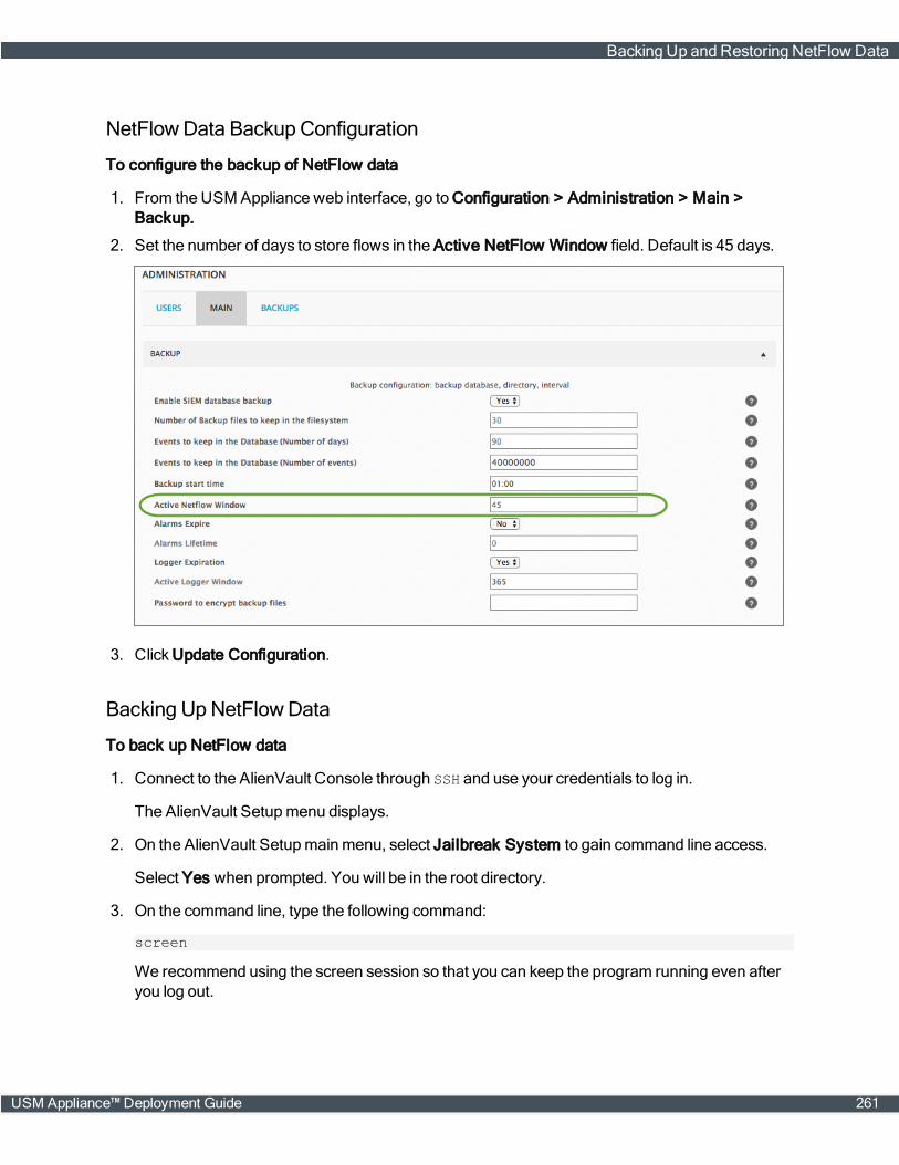
NetFlowData Backup Configuration
To configure the backup of NetFlow data
1. From the USM Appliance web interface, go to Configuration > Administration > Main >Backup.
2. Set the number of days to store flows in the Active NetFlow Window field. Default is 45 days.
3. Click Update Configuration.
Backing UpNetFlowData
To back up NetFlow data
1. Connect to the AlienVault Console through SSH and use your credentials to log in.
The AlienVault Setupmenu displays.
2. On the AlienVault Setupmainmenu, select Jailbreak System to gain command line access.
Select Yes when prompted. You will be in the root directory.
3. On the command line, type the following command:
screen
We recommend using the screen session so that you can keep the program running even afteryou log out.
Backing Up and Restoring NetFlow Data
USM Appliance™ Deployment Guide 261

4. Run the following command:
tar czf alienvault-netflow-`date +%s`.tgz /var/nfsen /var/cache/nfdump
Adding `date +%s` to the filename gives it a unique time stamp.
This procedure creates the alienvault-netflow-<timestamp>.tgz file. Transfer the file to thetarget system. You can use either an SFTP client onWindows, such as WinSCP; or the SCPprotocol on Linux.
Restoring NetFlowData
Before following the procedure below, you should have deployed the SAME version ofUSM Appliance. You should have transferred the backup files to the target system and place them inthe root directory.
To restore NetFlow data
1. Connect to the AlienVault Console through SSH and use your credentials to log in.
The AlienVault Setupmenu displays.
2. On the AlienVault Setupmainmenu, select Jailbreak System to gain command line access.
Select Yes when prompted. You will be in the root directory.
3. On the command line, type the following command:
screen
We recommend using the screen session so that you can keep the program running even afteryou log out.
4. Stop the following services so that they do not interfere with the process:
/etc/init.d/monit stop/etc/init.d/ossim-server stop/etc/init.d/ossim-agent stop/etc/init.d/ossim-framework stop/etc/init.d/alienvault-api stop
5. Extract the backup file into the '/' directory:
tar xvzf alienvault-netflow-<timestamp>.tgz -C /
6. Update file permissions:
tar tvzf alienvault-netflow-<timestamp>.tgz | tr -s ' ' > /root/file_listulimit -s 65536cd /for i in `cat /root/file_list | cut -f2 -d" " | sort -u`; do user=`echo $i| cut -f1 -d"/"`; group=`echo $i | cut -f2 -d"/"`; chown $user:$group`grep $i root/file_list | cut -f6 -d" " | xargs`; done
Backing Up and Restoring NetFlow Data
262 USM Appliance™ Deployment Guide
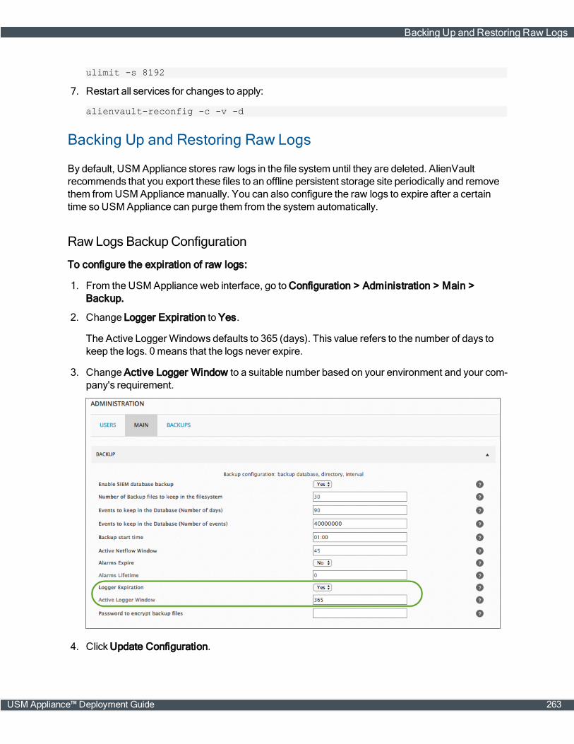
ulimit -s 8192
7. Restart all services for changes to apply:
alienvault-reconfig -c -v -d
Backing Up and Restoring Raw Logs
By default, USM Appliance stores raw logs in the file system until they are deleted. AlienVaultrecommends that you export these files to an offline persistent storage site periodically and removethem fromUSM Appliancemanually. You can also configure the raw logs to expire after a certaintime so USM Appliance can purge them from the system automatically.
Raw Logs Backup Configuration
To configure the expiration of raw logs:
1. From the USM Appliance web interface, go to Configuration > Administration > Main >Backup.
2. Change Logger Expiration to Yes.
The Active Logger Windows defaults to 365 (days). This value refers to the number of days tokeep the logs. 0means that the logs never expire.
3. Change Active Logger Window to a suitable number based on your environment and your com-pany's requirement.
4. Click Update Configuration.
Backing Up and Restoring Raw Logs
USM Appliance™ Deployment Guide 263
Backing UpRaw Logs
USM Appliance store raw logs in /var/ossim/logs and organizes them in this order: year, month,day, hour (UTC), and USM Appliance Sensor IP. For example, to find the raw logs reported bysensor 192.168.73.159 at 10 o'clock on August 5, 2016, navigate to/var/ossim/logs/2016/08/05/10/192.168.73.159.
To back up raw logs
1. Connect to the AlienVault Console through SSH and use your credentials to log in.
The AlienVault Setupmenu displays.
2. On the AlienVault Setupmainmenu, select Jailbreak System to gain command line access.
Select Yes when prompted. You will be in the root directory.
3.
On the command line, type the following command:
screen
We recommend using the screen session so that you can keep the program running even afteryou log out.
4. For efficiency, use the rsync protocol to transfer the raw logs to the destination:
Syntax:
rsync -av --progress /src_folder_path <username>@<dest_ip_address>:<dest_folder_path>
Example 1: Transferring raw logs of March 2017
rsync -av --progress /var/ossim/logs/2017/[email protected]:/var/ossim/logs/2017
Example 2: Transferring all raw logs of 2017
rsync -av --progress /var/ossim/logs/2017 [email protected]:/var/ossim/logs
Important: Leave out the trailing slash ('/') on the source so that the correspondingdirectory will be created at the destination.
The raw logs should be transferred to the destinedmachine, in this case, 10.10.10.10, and store inthe /var/ossim/logs directory.
Purging Raw Logs
After backing up the raw logs and transferring them to an external storage, you need to remove themfromUSM Appliancemanually.
Backing Up and Restoring Raw Logs
264 USM Appliance™ Deployment Guide
To remove raw logs
1. Connect to the AlienVault Console through SSH and use your credentials to log in.
The AlienVault Setupmenu displays.
2. Select Maintenance & Troubleshooting.
3. Select Maintain Disk and Logs.
4. Select Purge Logger Data.
5. Select Delete logger entries older than a date.
6. Enter a data in the YYYY/MM/DD format then press Enter <OK>.
USM Appliance will delete any raw logs older than the date specified.
Restoring Raw Logs
Before following the procedure below, you should have deployed the SAME version ofUSM Appliance. You should have transferred the backup files to the target system and place them inthe root directory.
You can also restore raw logs that were archived and purged from the sameUSM Applianceinstance in the past.
To restore raw logs
1. Connect to the AlienVault Console through SSH and use your credentials to log in.
The AlienVault Setupmenu displays.
2. On the AlienVault Setupmainmenu, select Jailbreak System to gain command line access.
Select Yes when prompted. You will be in the root directory.
3. On the command line, type the following command:
screen
We recommend using the screen session so that you can keep the program running even afteryou log out.
4. If not done already, use the rsync protocol to transfer the raw logs to /var/ossim/logsdirectory.
5. Change permission for raw logs:
chown -R www-data:alienvault /var/ossim/logs/searcheschown -R avserver:alienvault /var/ossim/logs/2017
Backing Up and Restoring Raw Logs
USM Appliance™ Deployment Guide 265
Backing Up and Restoring System Configuration
In USM Appliance, you can back up and restore system configurations including system profile,network configuration, inventory data, policies, plugins, correlation directives and other basicsettings. You can restore the configurations on a different USM Appliance system from a backup filethrough the AlienVault Console. You can alsomanage the configuration backups from theUSM Appliance webUI.
Note: It is not possible to upgrade fromAlienVault OSSIM to USM Appliance, but you canrestore AlienVault OSSIM configurations to USM Appliance or vice versa if they are the sameversion.
Backing Up Configurations
By default, USM Appliance backs up the system configurations at 7:00 am local time every day.These display as "Auto" under the Type column in the webUI. You can alsomanually run a backupat any time.
Each configuration backup file contains the following:
l Correlation directives
l HIDS configurations
l HIDS local rules (version 5.2.1 and later)
l Inventory data
l Plugins (both default and customized)
l Policies
l Syslog and logrotate configurations (version 5.2.1 and later)
l System configuration (networking, system profile, USM Appliance basic configuration settings)
Note: Security events and raw logs are NOT included in the configuration backup files.
USM Appliance stores its configuration backup files in the following location:
/var/alienvault/backup/configuration_<hostname>_<timestamp>.tar.gz
For example,
configuration_VirtualUSMAllInOne_1429616586.tar.gz
Because the integer string represents epoch time, the backup with the highest number denotes themost recent one.
USM Appliancemaintains 10 backups on each system, based on their time stamp.
Before starting the backup, USM Appliance verifies the following:
Backing Up and Restoring SystemConfiguration
266 USM Appliance™ Deployment Guide

l No re-configuration process is running.
l No other backup or restore processes are running.
l Sufficient disk space exists to restore the configuration backup.
Note: USM Appliance aborts the backup process if any of these checks fails.
Starting from version 5.2.5, USM Appliance will not generate any configuration backups, automaticor manual, until you set a password to encrypt the backup files. And you need to provide the samepassword to decrypt the file before a restoration.
To set up a password to encrypt the backup files
1. In the web interface, go to Configuration > Administration > Main > Backup.
2. In Password to encrypt backup files, type a password between 7 and 32 characters.
Important: Do not use the following characters in your password: " ;, |, &, <, >, \n,(, ), [, ], {, }, ?, *, ^, \".
3. Click Update Configuration.
To run a backup manually
1. In the webUI, go to Configuration > Administration > Backups > Configuration.
2. Click Run Backup Now.
A message appears showing when the last backup was run and asking if you want to continue.
3. Select Yes to start the backup.
These backups display as "Manual" under the Type column.
To see any error messages in the backup logs
1. Go to Configuration > Administration > Backups > Configuration.
2. Click View Backup Logs.
Backing Up a Child Server from the Federated Server
In a federated environment, where you have USM Appliance Sensors reporting to a USM ApplianceServer (child), which then reports to another USM Appliance Server (federated), keep the followinginmind:
l Each USM Appliance Server (whether a child or federated server) only triggers automaticbackups of itself and directly connected sensors. In other words, the federated server doesnot trigger automatic backups to its child servers.
l Each USM Appliance stores its own backup file.
You can select the child server on the federated server, but not the reverse. You can run amanualbackup of the child server from the federated server by following the standard backup procedure.
Backing Up and Restoring SystemConfiguration
USM Appliance™ Deployment Guide 267
To back up the child server from the federated server:
1. Go to Configuration > Administration > Backups > Configuration.
2. Choose which system you want to use by expanding Show Backups for.
3. Click Run Backup Now.
Restoring Configuration Backups
You can only restore a USM Appliance system from a backup file through the AlienVault Console.
Before running a restoration, USM Appliance verifies the following and aborts the restorationprocess if any of these checks fails:
l No re-configuration process is running.
l No other backup or restore processes are running.
l The backup profile matches the system profile. In other words, you cannot restore a backup filefrom the USM Appliance Server on the USM Appliance Sensor.
l Backup file version is the same as the target system. In other words, you can only restore aUSM Appliance version 5.4.3 backup on a system that is running USM Appliance version 5.4.3.
Note: You can restore an AlienVault OSSIM™ backup on a USM Appliance or vice versa,as long as they are the same version.
l Sufficient disk space exists to restore the configuration backup.
Before restoring a backup file, youmust transfer the file to the target system and place it in the/var/alienvault/backup/ directory. You can use either an SFTP client onWindows, suchas WinSCP; or the SCP protocol on Linux.
To restore a backup file
1. Connect to the AlienVault Console through SSH and use your credentials to log in.
The AlienVault Setupmenu displays.
2. Select Maintenance & Troubleshooting.
3. Select Backups.
4. Select Restore configuration backup.
5. Select the backup file you want to restore, click <OK> or press Enter.
6. Select <Yes> to continue.
7. Enter the password used to encrypt the backup files.
The restoration process starts.
After the process finishes, the system restarts automatically.
Backing Up and Restoring SystemConfiguration
268 USM Appliance™ Deployment Guide
Note: Your SSH connection will drop if the IP address of USM Appliance changes as aresult of the restoration.
8. Log in to display the AlienVault Setupmenu again.
9. Select System Preferences.
10. Select Reset AlienVault API Key.
To find out more, see Resetting the AlienVault API Key, on page 270.
Managing Configuration Backups
You canmanage the configuration backups on Configuration > Administration > Backups >Configuration.
The configuration backups display in a table format.
Column / Field Name Description
System System chosen for backup
Date Date and time when the backup was run.
Backup Backup category. Currently the only category is Configuration.
Type Backup Type. Supported values are Auto and Manual.
Version Version of the USM Appliance system.
Size Size of the backup file.
Download Saves the backup file to your local machine.
Columns / fields for configuration backups
By default, USM Appliance sorts the backups by their time stamps, with the latest one at the top.
To look for a backup
l Use the search box at the upper left corner.
Search fields are System (name or IP address), Date, or Type.
To download backups and store them locally
1. Locate the backup you'd like to download.
2. In the last column, click the download icon ( ).
Sample backup file format:
configuration_VirtualUSMAllInOne_1429616586.tar.gz
Because the integer string represents epoch time, the backup with the highest number denotesthemost recent one.
Backing Up and Restoring SystemConfiguration
USM Appliance™ Deployment Guide 269
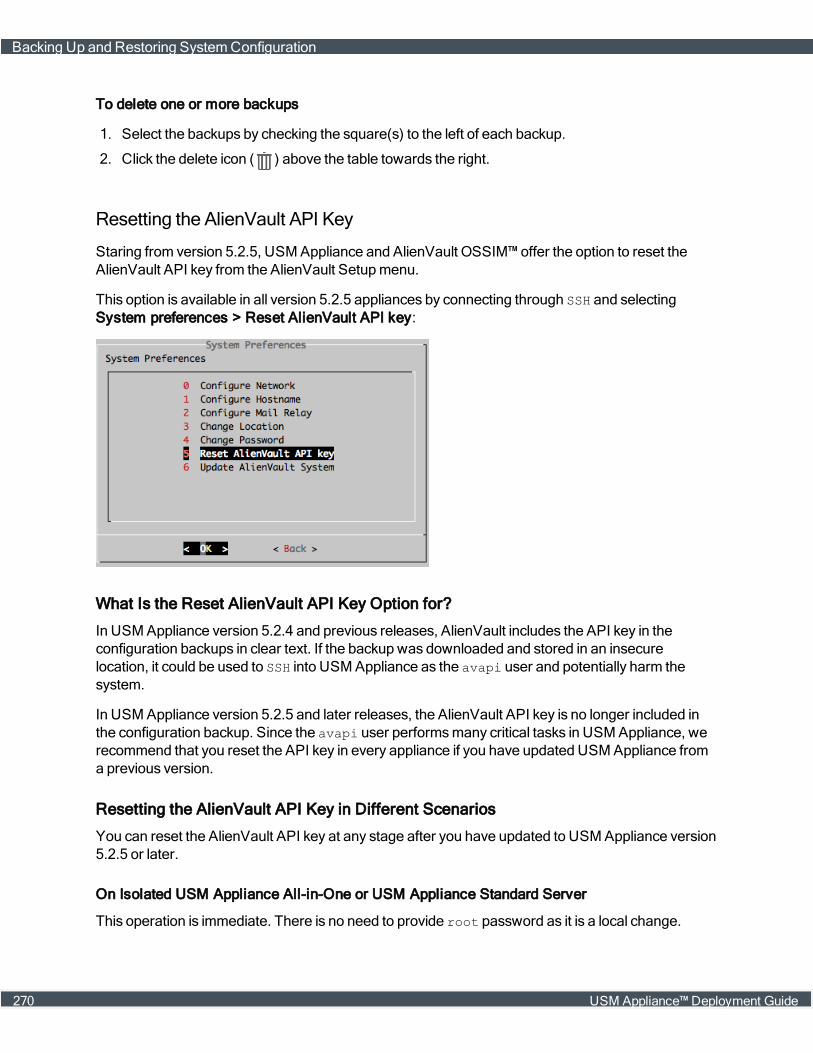
To delete one or more backups
1. Select the backups by checking the square(s) to the left of each backup.
2. Click the delete icon ( ) above the table towards the right.
Resetting the AlienVault API Key
Staring from version 5.2.5, USM Appliance and AlienVault OSSIM™ offer the option to reset theAlienVault API key from the AlienVault Setupmenu.
This option is available in all version 5.2.5 appliances by connecting through SSH and selectingSystem preferences > Reset AlienVault API key:
What Is the Reset AlienVault API Key Option for?
In USM Appliance version 5.2.4 and previous releases, AlienVault includes the API key in theconfiguration backups in clear text. If the backup was downloaded and stored in an insecurelocation, it could be used to SSH into USM Appliance as the avapi user and potentially harm thesystem.
In USM Appliance version 5.2.5 and later releases, the AlienVault API key is no longer included inthe configuration backup. Since the avapi user performsmany critical tasks in USM Appliance, werecommend that you reset the API key in every appliance if you have updated USM Appliance froma previous version.
Resetting the AlienVault API Key in Different Scenarios
You can reset the AlienVault API key at any stage after you have updated to USM Appliance version5.2.5 or later.
On Isolated USM Appliance All-in-One or USM Appliance Standard Server
This operation is immediate. There is no need to provide root password as it is a local change.
Backing Up and Restoring SystemConfiguration
270 USM Appliance™ Deployment Guide

Just select the option from the AlienVault Setupmenu and select Yes when prompted to regeneratethe new AlienVault API Key.
In a Distributed Deployment with More Than One USM Appliance Server or USM ApplianceSensor
This operation should be executed in all USM Appliance instances in order to fully reset theAlienVault API Key.
This should be executed from bottom-up considering the deployment hierarchy, in other words,USM Appliance Sensors first, followed byUSM Appliance Servers or USM Appliance All-in-Ones,followed by Federated Servers or USM Appliance Loggers.
The reasoning behind this is because choosing "Reset AlienVault API Key" will rewrite theauthorized_keys file completely. Thus, after resetting API key on a USM Appliance Sensor, it willno longer have the corresponding USM Appliance Server's key, therefore the USM ApplianceServer will not be able to communicate with the USM Appliance Sensor through the AlienVault API.But if you reset the AlienVault API key on the USM Appliance Server next, the USM ApplianceServer sends it's new key to the USM Appliance Sensor thus restoring the API connectivity.
Note: In distributed deployments, where you havemore than one USM Appliance deployed,ensure that you know the password of the root user to the directly connected appliances asthey are required to reset the AlienVault API keys.
Migrating Your USM Appliance Deployment
For testing or disaster recovery purposes, youmay be tasked to duplicate your USM Appliancedeployment from one VMware host to another. On the other hand, youmaywant to migrateUSM Appliance from one deployment option to a different one, such as fromVMware to Hyper-V.This topic covers both scenarios, except that youmust acquire a new license if you want to switch toa different platform. Please contact AlienVault Support for your request.
Migrating your USM Appliance deployment consists of two tasks:
Migrating Your USM Appliance Deployment
USM Appliance™ Deployment Guide 271
Backing up Your Current USM Appliance Deployment
USM Appliance does not provide a tool to back up the system as a whole. You need to back up yourdata and system configurations separately, and then transfer them to the other USM Appliancedeployment for restoration.
To back up your USM Appliance deployment
1. Generate a configuration backup from the webUI. For instructions, see Backing UpConfigurations.
Note: You need to perform the following steps from the command line, through theAlienVault Console.
2. Connect to the AlienVault Console through SSH and use your credentials to log in.
The AlienVault Setupmenu displays.
3. On the AlienVault Setupmainmenu, select Jailbreak System to gain command line access.
Select Yes when prompted. You will be in the root directory.
4. On the command line, type the following command:
screen
We recommend using the screen session so that you can keep the program running even afteryou log out.
5. Stop the following services so that they do not interfere with the process:
/etc/init.d/monit stop/etc/init.d/ossim-server stop/etc/init.d/ossim-agent stop/etc/init.d/ossim-framework stop/etc/init.d/alienvault-api stop
6. Back up the alarms:
mysqldump -p`grep ^pass /etc/ossim/ossim_setup.conf | sed 's/pass=//'` --no-autocommit --single-transaction alienvault event extra_data idm_dataotx_data backlog_event backlog alarm component_tags alarm_ctxs alarm_netsalarm_hosts | pigz > alienvault-alarms-`date +%s`.sql.gz
Adding `date +%s` to the filename gives it a unique time stamp.
7. Back up the events:
Note: The example below illustrates how to transfer files fromUSM Appliance to amachine on your network. If you have the new USM Appliance instance already deployed,you can transfer the files to the new system directly.
This step involves two parts:
Migrating Your USM Appliance Deployment
272 USM Appliance™ Deployment Guide
a. Back up the events in the database:
mysqldump -p`grep ^pass /etc/ossim/ossim_setup.conf | sed 's/pass=//'`--no-autocommit --single-transaction --databases alienvault_siem | pigz> alienvault-events-`date +%s`.sql.gz
Adding `date +%s` to the filename gives it a unique time stamp.
b. Using the rsync protocol, transfer the old events to the destination:
Syntax:
rsync -av --progress /src_folder_path <username>@<dest_ip_address>:<dest_folder_path>
Example:
rsync -av --progress /var/lib/ossim/[email protected]:/var/lib/ossim
Important: Leave out the trailing slash ('/') on the source so that the correspondingdirectory will be created at the destination.
8. Back upMongoDB:
a. Back up theMongoDB database and create the dump directory:
mongodump --host localhost
b. Compress the file:
tar cvfz alienvault-mongodb-`date +%s`.tgz dump
Adding `date +%s` to the filename gives it a unique time stamp.
c. Remove the dump directory:
rm -rf ./dump
9. Back up NetFlow Data, if using:
tar czf alienvault-netflow-`date +%s`.tgz /var/nfsen /var/cache/nfdump
Adding `date +%s` to the filename gives it a unique time stamp.
10. Back up the Raw Logs:
Note: The example below illustrates how to transfer files fromUSM Appliance to amachine on your network. If you have the new USM Appliance instance already deployed,you can transfer the files to the new system directly.
For efficiency, use the rsync protocol to transfer the raw logs to the destination:
Syntax:
Migrating Your USM Appliance Deployment
USM Appliance™ Deployment Guide 273
rsync -av --progress /src_folder_path <username>@<dest_ip_address>:<dest_folder_path>
Example 1: Transferring raw logs of March 2017
rsync -av --progress /var/ossim/logs/2017/[email protected]:/var/ossim/logs/2017
Example 2: Transferring all raw logs of 2017
rsync -av --progress /var/ossim/logs/2017 [email protected]:/var/ossim/logs
Important: Leave out the trailing slash ('/') on the source so that the correspondingdirectory will be created at the destination.
11. At this step, you have produced the following files:
/root/alienvault-alarms-<timestamp>.sql.gz/root/alienvault-events-<timestamp>.sql.gz/root/alienvault-mongodb-<timestamp>.tgz/root/alienvault-netflow-<timestamp>.tgz
You should also have a file similar to below generated by the configuration backup:
/var/alienvault/backup/configuration_<hostname>_<timestamp>.tar.gz
12. Transfer all backup files to your new USM Appliance deployment or an interim system. You canuse either an SFTP client onWindows, such as WinSCP; or the SCP protocol on Linux.
Restoring USM Appliance in the New Deployment
Before following the procedure below, you should have deployed the SAME version ofUSM Appliance. You should have transferred the backup files to the target system and place them inthe root directory.
Important: If you are restoring USM Appliance to a different platform such as fromVMware toHyper-V, youmust acquire a new license. Please contact AlienVault Support for your request.
To restore your USM Appliance deployment
1. Connect to the AlienVault Console through SSH and use your credentials to log in.
The AlienVault Setupmenu displays.
2. On the AlienVault Setupmainmenu, select Jailbreak System to gain command line access.
Select Yes when prompted. You will be in the root directory.
3. On the command line, type the following command:
screen
We recommend using the screen session so that you can keep the program running even afteryou log out.
Migrating Your USM Appliance Deployment
274 USM Appliance™ Deployment Guide
4. Stop the following services so that they do not interfere with the process:
/etc/init.d/monit stop/etc/init.d/ossim-server stop/etc/init.d/ossim-agent stop/etc/init.d/ossim-framework stop/etc/init.d/alienvault-api stop
5. Restore the alarms:
zcat alienvault-alarms-<timestamp>.sql.gz | ossim-db
6. Restore the events:
a. Restore events into the database:
zcat alienvault-events-<timestamp>.sql.gz | ossim-db
b. If not done already, use the rsync protocol to transfer the event backup files to/var/lib/ossim directory.
c. Change permission on event backup files:
chown root:alienvault /var/lib/ossim/backupchown root:root /var/lib/ossim/backup/*
7. RestoreMongoDB:
a. Extract the file:
tar xvzf alienvault-mongodb-<timestamp>.tgz
b. Restore the backup file
mongorestore --db inventory dump/inventory
c. Remove the dump directory:
rm -rf ./dump
8. Restore NetFlow data, if using:
a. Extract the backup file into the '/' directory:
tar xvzf alienvault-netflow-<timestamp>.tgz -C /
b. Update file permissions:
tar tvzf alienvault-netflow-<timestamp>.tgz | tr -s ' ' > /root/file_listulimit -s 65536cd /for i in `cat /root/file_list | cut -f2 -d" " | sort -u`; do user=`echo$i | cut -f1 -d"/"`; group=`echo $i | cut -f2 -d"/"`; chown$user:$group `grep $i root/file_list | cut -f6 -d" " | xargs`; doneulimit -s 8192
Migrating Your USM Appliance Deployment
USM Appliance™ Deployment Guide 275

9. Restore Raw Logs:
a. If not done already, use the rsync protocol to transfer the raw logs to /var/ossim/logsdirectory.
b. Change permission for raw logs:
chown -R www-data:alienvault /var/ossim/logs/searcheschown -R avserver:alienvault /var/ossim/logs/2017
10. Restore system configurations:
a. Copy or move the configuration backup file to the /var/alienvault/backup directory.
b. Type exit and then press Enter to return to the AlienVault Setupmenu.
c. Select Maintenance & Troubleshooting.
d. Select Backups.
e. Select Restore configuration backup.
f. Select the backup file you want to restore, click <OK> or press Enter.
g. Select <Yes> to continue.
h. Enter the password used to encrypt the backup files.
The restoration process starts.
After the process finishes, the system restarts automatically.
Note: Your SSH connection will drop if the IP address of USM Appliance changes as aresult of the restoration.
i. Log in to display the AlienVault Setupmenu again.
j. Select System Preferences.
k. Select Reset AlienVault API Key.
To find out more, see Resetting the AlienVault API Key, on page 270.
11. Return to the AlienVault Setupmainmenu, select Reboot Appliance, click <OK> or pressEnter.
Restoring Software on a USM Appliance Hardware
Sometimes youmaywant to restore the software on a USM Appliance hardware appliance to itsfactory status. To do this,
Restoring Software on a USM Appliance Hardware
276 USM Appliance™ Deployment Guide
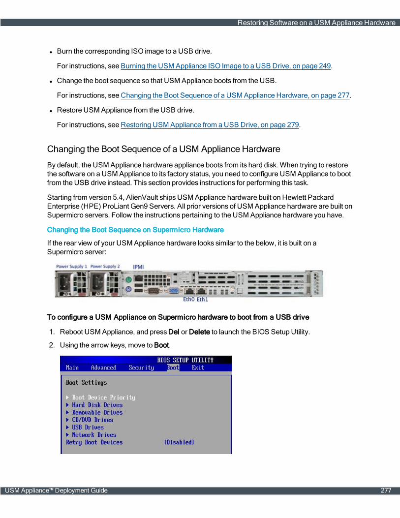
l Burn the corresponding ISO image to a USB drive.
For instructions, see Burning the USM Appliance ISO Image to a USB Drive, on page 249.
l Change the boot sequence so that USM Appliance boots from the USB.
For instructions, see Changing the Boot Sequence of a USM Appliance Hardware, on page 277.
l Restore USM Appliance from the USB drive.
For instructions, see Restoring USM Appliance from aUSB Drive, on page 279.
Changing the Boot Sequence of a USM Appliance Hardware
By default, the USM Appliance hardware appliance boots from its hard disk. When trying to restorethe software on a USM Appliance to its factory status, you need to configure USM Appliance to bootfrom the USB drive instead. This section provides instructions for performing this task.
Starting from version 5.4, AlienVault ships USM Appliance hardware built on Hewlett PackardEnterprise (HPE) ProLiant Gen9 Servers. All prior versions of USM Appliance hardware are built onSupermicro servers. Follow the instructions pertaining to the USM Appliance hardware you have.
Changing the Boot Sequence on Supermicro Hardware
If the rear view of your USM Appliance hardware looks similar to the below, it is built on aSupermicro server:
To configure a USM Appliance on Supermicro hardware to boot from a USB drive
1. Reboot USM Appliance, and pressDel or Delete to launch the BIOS Setup Utility.
2. Using the arrow keys, move to Boot.
Restoring Software on a USM Appliance Hardware
USM Appliance™ Deployment Guide 277

3. On Boot Settings, move the cursor to Boot Device Priority and press Enter.
4. On Boot Device Priority, move the cursor to 1st Boot Device and select your USB device byusing the + and – keys.
5. To exit, press Esc.
6. On Exit Options, move the cursor to Save Changes and Exit and press Enter.
7. Press Enter again to confirm.
8. Reboot USM Appliance.
Changing the Boot Sequence on HPE Hardware
If the rear view of your USM Appliance hardware looks similar to the below, it is built on an HPEProLiant DL120Gen9 Server:
To configure a USM Appliance on HPE hardware to boot from a USB drive
1. Power on or restart USM Appliance.
2. Press the F9 key, when prompted, to enter System Utilities.
3. Select System Configuration and then BIOS/Platform Configuration (RBSU).
4. Select Boot Options and then Legacy BIOS Boot Order, press Enter.
5. Use the "+" or "-" key tomove the USB entry to the top of the boot list.
6. Press F10 to save your changes.
7. Restart the server.
Note: The USM Appliance Remote Sensor hardware is built on HPE ProLiant DL20Gen9Servers, but you can follow the same procedure above to change the boot sequence.
Restoring Software on a USM Appliance Hardware
278 USM Appliance™ Deployment Guide

Restoring USM Appliance from aUSBDrive
Prerequisite
l Burn the corresponding ISO image to a USB drive.
l Change the boot sequence so that USM Appliance boots from the USB.
Warning: The process deletes all the data stored in your USM Appliance.
To restore USM Appliance from the USB drive
1. If not done already, insert the USB drive to your USM Appliance hardware appliance.
2. Reboot USM Appliance.
3. Select Restore AlienVault <your-Appliance-Type>.
Customers restoring to USM Appliance versions 5.2.3 and later see the following screen:
Customers restoring to USM Appliance versions up to 5.2.2 see screen below instead:
4. To continue, enter y.
Restoring Software on a USM Appliance Hardware
USM Appliance™ Deployment Guide 279

5. Wait for the restoration process to complete.
6. After the restoration process finishes, disconnect your USB drive before the system reboots.
Restoring Software on a USM Appliance Hardware
280 USM Appliance™ Deployment Guide
Note: If you forget to remove it, USM Appliance will boot from the USB drive again.
USM Appliance reboots and displays the initial login screen of the version you restore to.
7. Login as the root user using the system-generated password displayed on the screen.
8. Change the root user password as prompted.
9. Reboot the system again to finish the data restoration.
After the second reboot, the appliance is ready for you to use.
For other instructions regarding initial configurations, see USMAppliance Initial Setup.
Restoring Software on a USM Appliance Hardware
USM Appliance™ Deployment Guide 281
SystemMaintenance
This section covers the following subtopics:
Purging Old System Logs or Clearing SystemUpdate Caches 283
Updating the AlienVault License Key in USM Appliance 283
Replacing Disk Drives or Power Supplies on USM Appliance Hardware 284
USM Appliance™ Deployment Guide 282
Purging Old System Logs or Clearing System Update Caches
You should delete USM Appliance system logs and/or old event logs on a regular basis, otherwisethe appliancemay run out of space. Starting from version 5.2.1, USM Appliance adds a pre-check toits update-script so that the update fails if the appliance does not have enough disk space.
To purge old system logs and/or clear system update caches
1. Connect to the AlienVault Console through SSH and use your credentials to log in.
The AlienVault Setupmenu displays.
2. Select Maintenance & Troubleshooting.
3. Select Maintain Disk and Logs.
4. Select Clear System Update Caches.
5. Alternatively, select Purge Old System Logs.
6. Press Enter after the process completes.
Updating the AlienVault License Key in USM Appliance
Occasionally, youmay need to replace the AlienVault license key in your USMAppliance instance.For example, youmay need to replace a trial license with a perpetual license, or you havemigratedUSMAppliance fromVMware to Hyper-V andmust use a different license key.
To replace the AlienApp license key in USM Appliance
1. Connect to the AlienVault Console through SSH and use your credentials to log in.
The AlienVault Setupmenu displays.
2. Select Maintenance & Troubleshooting.
3. Select Update license information.
4. Select Online Registration if you have Internet access. You will be prompted to enter the newlicense key:
Purging Old System Logs or Clearing SystemUpdate Caches
283 USM Appliance™ Deployment Guide
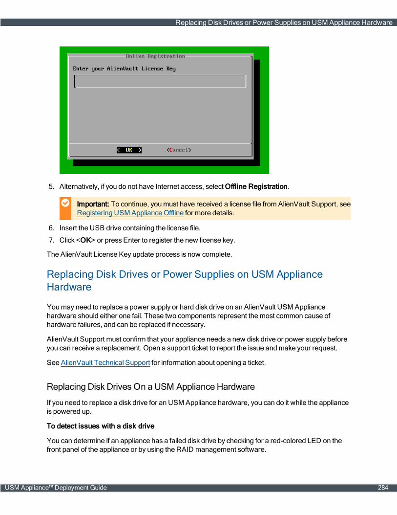
5. Alternatively, if you do not have Internet access, select Offline Registration.
Important: To continue, youmust have received a license file fromAlienVault Support, seeRegistering USM ApplianceOffline for more details.
6. Insert the USB drive containing the license file.
7. Click <OK> or press Enter to register the new license key.
The AlienVault License Key update process is now complete.
Replacing Disk Drives or Power Supplies on USM ApplianceHardware
Youmay need to replace a power supply or hard disk drive on an AlienVault USM Appliancehardware should either one fail. These two components represent themost common cause ofhardware failures, and can be replaced if necessary.
AlienVault Support must confirm that your appliance needs a new disk drive or power supply beforeyou can receive a replacement. Open a support ticket to report the issue andmake your request.
See AlienVault Technical Support for information about opening a ticket.
Replacing Disk Drives On aUSM Appliance Hardware
If you need to replace a disk drive for an USM Appliance hardware, you can do it while the applianceis powered up.
To detect issues with a disk drive
You can determine if an appliance has a failed disk drive by checking for a red-colored LED on thefront panel of the appliance or by using the RAID management software.
Replacing Disk Drives or Power Supplies on USM Appliance Hardware
USM Appliance™ Deployment Guide 284
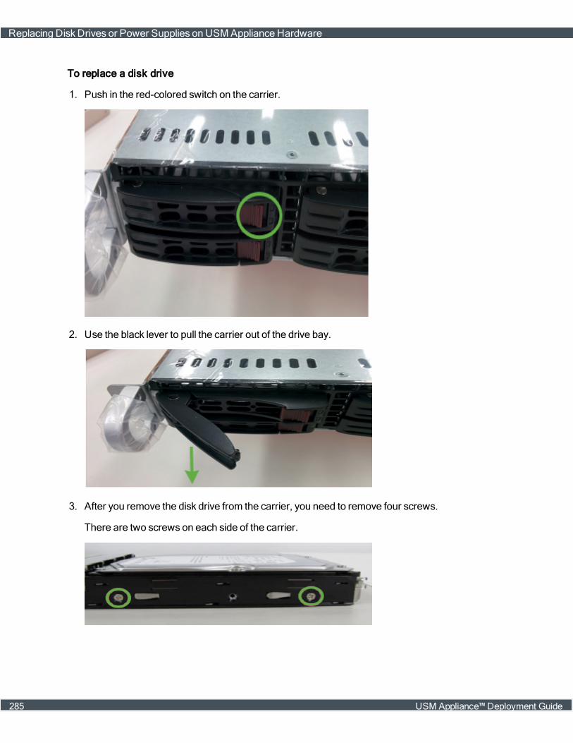
To replace a disk drive
1. Push in the red-colored switch on the carrier.
2. Use the black lever to pull the carrier out of the drive bay.
3. After you remove the disk drive from the carrier, you need to remove four screws.
There are two screws on each side of the carrier.
Replacing Disk Drives or Power Supplies on USM Appliance Hardware
285 USM Appliance™ Deployment Guide

4. Confirm the replacement is the same size or larger than the failed drive.
5. Remove the defective disk drive from the tray.
6. Insert the new drive with the SATA connections facing the rear of the tray.
7. Make sure the screw holes are aligned before hand-tightening the screws.
8. Slide the drive into the bay and press the black lever to lock it.
Replacing Disk Drives or Power Supplies on USM Appliance Hardware
USM Appliance™ Deployment Guide 286
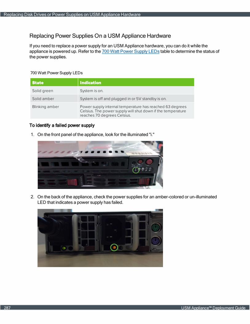
Replacing Power Supplies On aUSM Appliance Hardware
If you need to replace a power supply for an USM Appliance hardware, you can do it while theappliance is powered up. Refer to the 700Watt Power Supply LEDs table to determine the status ofthe power supplies.
State Indication
Solid green System is on.
Solid amber System is off and plugged in or 5V standby is on.
Blinking amber Power supply internal temperature has reached 63 degreesCelsius. The power supply will shut down if the temperaturereaches 70 degrees Celsius.
700Watt Power Supply LEDs
To identify a failed power supply
1. On the front panel of the appliance, look for the illuminated "i."
2. On the back of the appliance, check the power supplies for an amber-colored or un-illuminatedLED that indicates a power supply has failed.
Replacing Disk Drives or Power Supplies on USM Appliance Hardware
287 USM Appliance™ Deployment Guide
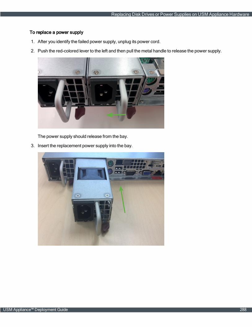
To replace a power supply
1. After you identify the failed power supply, unplug its power cord.
2. Push the red-colored lever to the left and then pull themetal handle to release the power supply.
The power supply should release from the bay.
3. Insert the replacement power supply into the bay.
Replacing Disk Drives or Power Supplies on USM Appliance Hardware
USM Appliance™ Deployment Guide 288
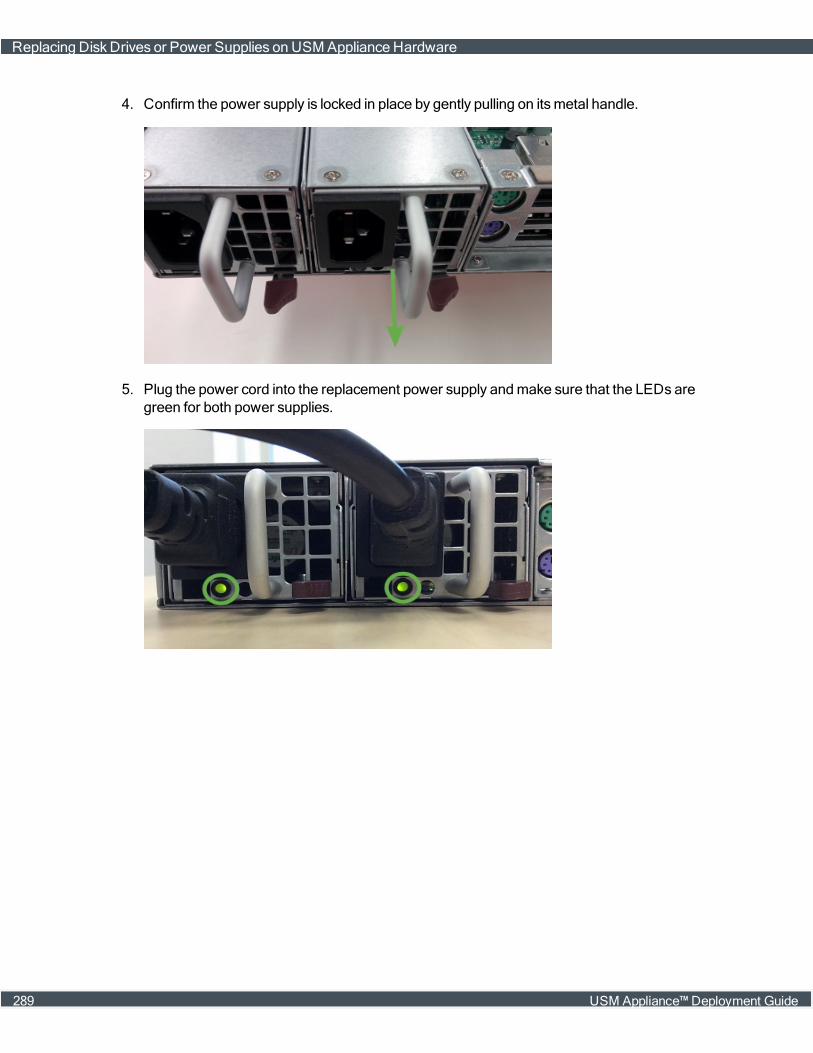
4. Confirm the power supply is locked in place by gently pulling on itsmetal handle.
5. Plug the power cord into the replacement power supply andmake sure that the LEDs aregreen for both power supplies.
Replacing Disk Drives or Power Supplies on USM Appliance Hardware
289 USM Appliance™ Deployment Guide
Remote Support
Topics covered in this section include the following:
About Remote Support 291
Remote Support Prerequisites 291
Using Remote Support 291
USM Appliance™ Deployment Guide 290
About Remote Support
Remote Support opens a secure, encrypted connection to the AlienVault Support Server throughthe USM Appliance web interface or the AlienVault console. This allows the AlienVault Support staffto access, diagnose, and resolve any problems occurring with a USM Appliance component.Remote Support allows the AlienVault Support staff to work on solving the issues independently,after you have connected your USM Appliance components to the Support Server.
All data exchanged with AlienVault Support is encrypted for security. The information exchanged isonly available to AlienVault Support or the Engineering teams.
Typically, you open a ticket with AlienVault Support first and only establish a remote supportconnection upon their request. You can establishmultiple sessions using the same ticket number fordifferent USM Appliance components. But a support engineer may ask you to open a new ticket if itis an unrelated issue. During the remote support session you can communicate with the AlienVaultSupport team by phone or email at any time.
Remote Support Prerequisites
To use Remote Support, you will need the following:
l The ticket number you received fromAlienVault Support.
l An Internet connection for themachine establishing the remote connection.
l A connection to TCP Ports 22 and 443 at tractorbeam.alienvault.com that allows forcommunication between the Support Server and the USM Appliance component beingdiagnosed.
Important: Because SSH does not support a proxy configuration, you cannot use a proxyserver for remote support.
Using Remote Support
UseRemote Support to allow AlienVault Support to access and diagnose the USM Appliancecomponents you identified in the support ticket. You can establish the connection either from theUSM Appliance webUI or the AlienVault console.
To run remote support from the USM Appliance web UI
1. In the USM Appliance web interface, go to Support > Support Tools > Remote Support.
2. From the Add Connection list, select the component you want AlienVault Support to diagnose.
3. In the Ticket Number field, type the 8-digit ticket number.
Important: Be careful not to include any spaces before or after the ticket number.
4. Click Connect.
About Remote Support
291 USM Appliance™ Deployment Guide

USM Appliance displays a statusmessage indicating that it is in the process of establishing atunnel.
Note: If the Support Server cannot validate the ticket number, USM Appliance displays anerror message. If this occurs, contact AlienVault Support again.
After the Support Server establishes a connection, the Open Connections table displays theactive connections to the components being diagnosed, and their respective ports.
The Support Server also sends you an automated email that it hasmade a connection.
When AlienVault Support completeswork on the issue, they communicate their results andupdate the ticket. You can request a log of all their activity at this point, or you can request it laterby phone or email.
5. After your ticket has been resolved, click Disconnect next to the active connection you want toend.
You should receive another automated email informing you that the connection has ended.
Using Remote Support
USM Appliance™ Deployment Guide 292
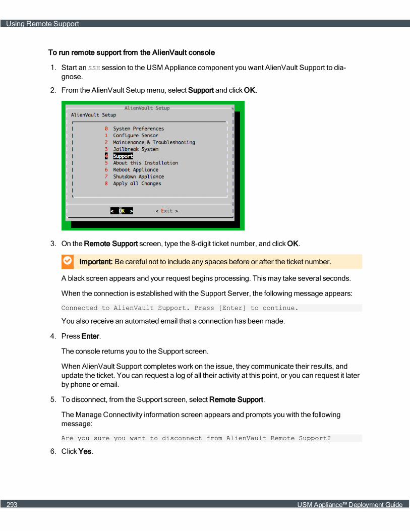
To run remote support from the AlienVault console
1. Start an SSH session to the USM Appliance component you want AlienVault Support to dia-gnose.
2. From the AlienVault Setupmenu, select Support and clickOK.
3. On the Remote Support screen, type the 8-digit ticket number, and clickOK.
Important: Be careful not to include any spaces before or after the ticket number.
A black screen appears and your request begins processing. Thismay take several seconds.
When the connection is established with the Support Server, the followingmessage appears:
Connected to AlienVault Support. Press [Enter] to continue.
You also receive an automated email that a connection has beenmade.
4. Press Enter.
The console returns you to the Support screen.
When AlienVault Support completeswork on the issue, they communicate their results, andupdate the ticket. You can request a log of all their activity at this point, or you can request it laterby phone or email.
5. To disconnect, from the Support screen, select Remote Support.
TheManage Connectivity information screen appears and prompts you with the followingmessage:
Are you sure you want to disconnect from AlienVault Remote Support?
6. Click Yes.
Using Remote Support
293 USM Appliance™ Deployment Guide
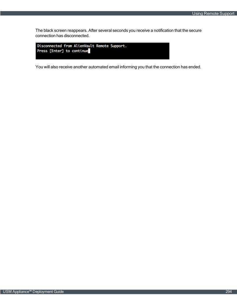
The black screen reappears. After several seconds you receive a notification that the secureconnection has disconnected.
You will also receive another automated email informing you that the connection has ended.
Using Remote Support
USM Appliance™ Deployment Guide 294