using the cryptographic service engine...
TRANSCRIPT
1 IntroductionThis application note describes the features offered by theCryptographic Services Engine (CSE) module which, for thefirst time has been implemented on the MPC564xB/C device.The module implements the security functions described in theSecure Hardware Extension (SHE) functional specification1.By reading this application note, the user will get an overviewof the reasons for implementing the CSE module and how itcan be used in typical automotive application use cases to helpprotect application code and inter module communication.This application note will show the basic features and willprovide the user a first guidance for the most typical functionsto be used with CSE in the form of a GreenHills exampleproject. However, it is not within the scope of this applicationnote to discuss the details of the SHE specification. Thisapplication note will focus on the hardware features providedby the CSE module and it is implied that the user is acquaintedwith the content of the SHE specification.
Why is cryptography needed?
Today, the modern electronic industry has the same problemwhich Julius Caesar faced 2000 years ago; about transmittinginformation in a secure and trusted manner between parties.Cryptography helps reaching this goal to exchange secure
1. SHE - Secure Hardware Extension functional specificationVersion1.1 (rev4)
Freescale Semiconductor Document Number: AN4234
Application Note Rev. 0, 06/2011
Using the Cryptographic ServiceEngine (CSE)An introduction to the CSE module
by: Geoff Emerson, Jurgen Frank, Stefan LuellmannApplications Engineering, Microcontroller Solutions Group
© 2011 Freescale Semiconductor, Inc.
Contents
1 Introduction.......................................................................1
2 CSE...................................................................................5
3 Example use cases-mini lifecycle...................................18
4 Conclusion......................................................................19
5 Glossary..........................................................................19
6 References.......................................................................20
A .........................................................................................20
B .........................................................................................22
C .........................................................................................25
D .........................................................................................26
information and to prove the authenticity. In the automotive area, cryptography helps to implement use-cases or systems likethe following:
• Immobilizers• Component protection• Secure flash updates• Protecting data sets (e.g. mileage)• Feature management via Digital-Right-Management (DRM)• Secure communication• IP protection• Car to X communication
Many more use-cases exist already and will come in the future. It should be noted that CSE is not intended to be used toencrypt the code flash contents.
1.1 AES algorithmSHE defines that the Advanced Encryption Standard (AES) algorithm is used for cryptographic operations. The AESalgorithm is described in AES algorithm.
1.2 Cipher modes overviewBlock ciphers like the AES algorithm, work with a defined granularity, often 64 bits or 128 bits. The simplest way to encodedata is to split the message in the cipher specific granularity. In this case, the cipher output will depend only on the key andthe input value. The drawback of this cipher mode, which is called Electronic Code Book (ECB), is that the same inputvalues will be decoded into the same output values. This allows attackers the opportunity to use statistical analysis (forexample, in a normal text some letter combinations occur much more often than others).
To overcome this issue other cipher modes were developed like the Cipher-block chaining (CBC), Cipher feedback (CFB),Output feedback (OFB) and Counter (CTR) mode.
The CSE module supports only the ECB and the CBC mode which are described in the following section:
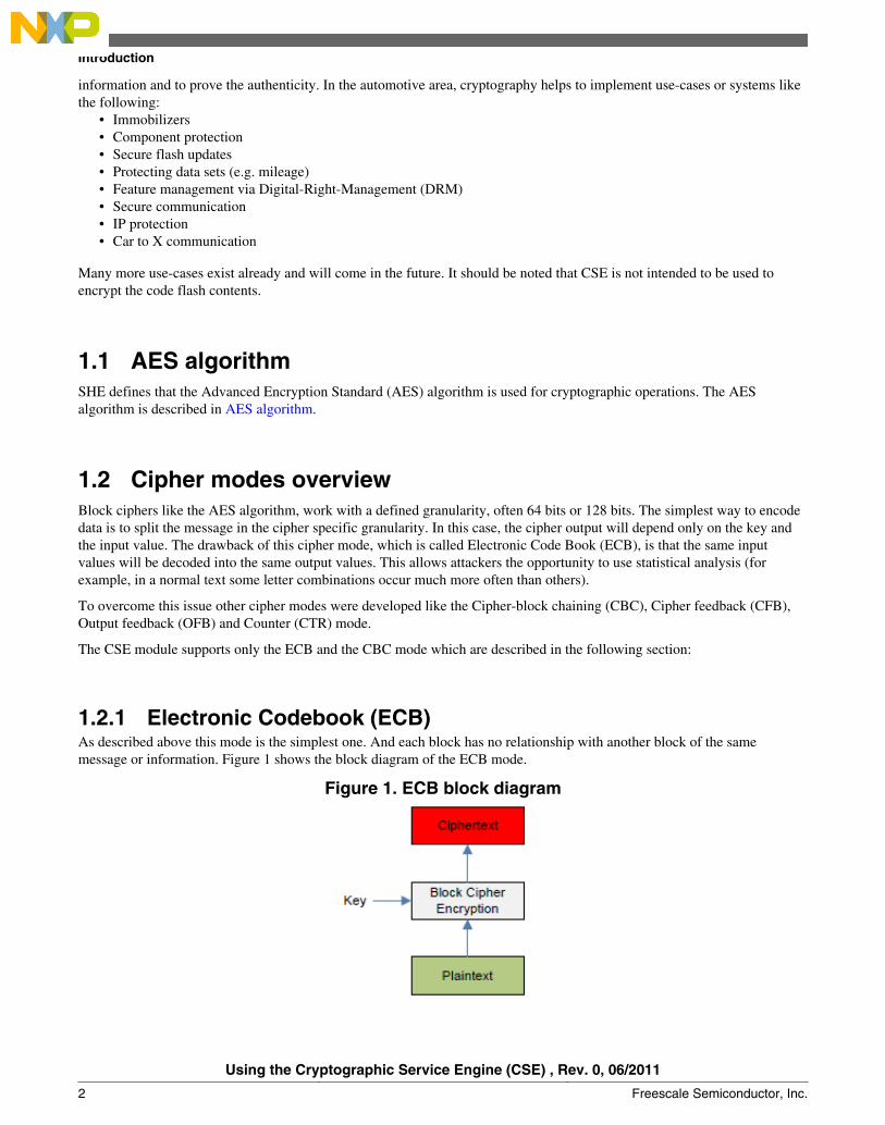
1.2.1 Electronic Codebook (ECB)As described above this mode is the simplest one. And each block has no relationship with another block of the samemessage or information. Figure 1 shows the block diagram of the ECB mode.
Figure 1. ECB block diagram
Introduction
Using the Cryptographic Service Engine (CSE) , Rev. 0, 06/2011
2 Freescale Semiconductor, Inc.
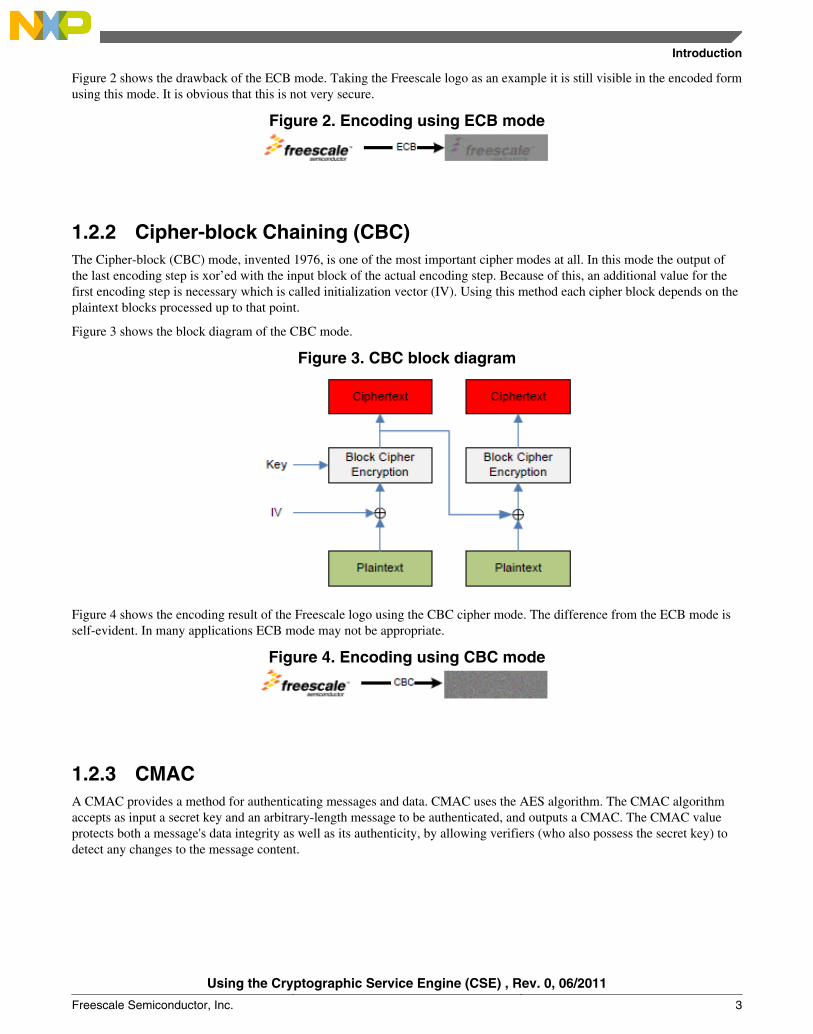
Figure 2 shows the drawback of the ECB mode. Taking the Freescale logo as an example it is still visible in the encoded formusing this mode. It is obvious that this is not very secure.
Figure 2. Encoding using ECB mode
1.2.2 Cipher-block Chaining (CBC)The Cipher-block (CBC) mode, invented 1976, is one of the most important cipher modes at all. In this mode the output ofthe last encoding step is xor’ed with the input block of the actual encoding step. Because of this, an additional value for thefirst encoding step is necessary which is called initialization vector (IV). Using this method each cipher block depends on theplaintext blocks processed up to that point.
Figure 3 shows the block diagram of the CBC mode.
Figure 3. CBC block diagram
Figure 4 shows the encoding result of the Freescale logo using the CBC cipher mode. The difference from the ECB mode isself-evident. In many applications ECB mode may not be appropriate.
Figure 4. Encoding using CBC mode
1.2.3 CMACA CMAC provides a method for authenticating messages and data. CMAC uses the AES algorithm. The CMAC algorithmaccepts as input a secret key and an arbitrary-length message to be authenticated, and outputs a CMAC. The CMAC valueprotects both a message's data integrity as well as its authenticity, by allowing verifiers (who also possess the secret key) todetect any changes to the message content.
Introduction
Using the Cryptographic Service Engine (CSE) , Rev. 0, 06/2011
Freescale Semiconductor, Inc. 3
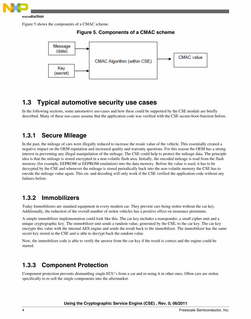
Figure 5 shows the components of a CMAC scheme.
Figure 5. Components of a CMAC scheme
1.3 Typical automotive security use casesIn the following sections, some automotive use-cases and how these could be supported by the CSE module are brieflydescribed. Many of these use-cases assume that the application code was verified with the CSE secure-boot-function before.
1.3.1 Secure MileageIn the past, the mileage of cars were illegally reduced to increase the resale value of the vehicle. This essentially created anegative impact on the OEM reputation and increased quality and warranty questions. For this reason the OEM has a stronginterest in preventing any illegal manipulation of the mileage. The CSE could help to protect the mileage data. The principleidea is that the mileage is stored encrypted in a non-volatile flash area. Initially, the encoded mileage is read from the flashmemory (for example, EEPROM or EEPROM emulation) into the data memory. Before the value is used, it has to bedecrypted by the CSE and whenever the mileage is stored periodically back into the non-volatile memory the CSE has toencode the mileage value again. This en- and decoding will only work if the CSE verified the application code without anyfailures before.
1.3.2 ImmobilizersToday Immobilizers are standard equipment in every modern car. They prevent cars being stolen without the car key.Additionally, the reduction of the overall number of stolen vehicles has a positive effect on insurance premiums.
A simple immobilizer implementation could look like this. The car key includes a transponder, a small cipher unit and aunique cryptographic key. The immobilizer unit sends a random value, generated by the CSE, to the car key. The car keyencrypts this value with the internal AES engine and sends the result back to the immobilizer. The immobilizer has the samesecret key stored in the CSE and is able to decrypt back the random value.
Now, the immobilizer code is able to verify the answer from the car key if the result is correct and the engine could bestarted.
1.3.3 Component ProtectionComponent protection prevents dismantling single ECU’s from a car and re-using it in other ones. Often cars are stolenspecifically to re-sell the single components into the aftermarket.
Introduction
Using the Cryptographic Service Engine (CSE) , Rev. 0, 06/2011
4 Freescale Semiconductor, Inc.
The OEM can now address several issues with a secure component protection scheme. First they can reduce the number ofstolen cars, secondly they can prevent any negative impact on reputation and quality and thirdly they can protect their ownaftermarket business.
A component protection system based on the CSE may look like this. The most valuable ECU’s will include a controllerwhich has a CSE module. A master node which may be assigned by design or dynamically with a specific algorithm will pollall ECU’s of the component protection system and request a specific answer (e.g. the unique ID in encoded from). In thiscase only ECU’s with the right secret key will be able to send back a valid response. Additionally, the master node can cross-check the unique ID with a database of all assembled modules in this specific car.
This component check can be done periodically while the car is used. If the system detects an unauthorized ECU in the carnetwork it is able to react on it.
1.3.4 Flash programming/firmware updatesThe CSE supports secure flash programming by the means of Cipher based message authentication code (CMAC)calculation. The application code will verify each block of the new flash image by re-calculating the CMAC value andcompare it with the offline pre-calculated value which is part of the flash image. This check will only be verified when thesame secret key was used for the CMAC calculation. This use case is presented and discussed in AN4235 – Using CSE toprotect your application via a circle of trust.
2 CSEThe Cryptographic Services Engine (CSE) is a peripheral module that implements the security functions described in theSecure Hardware Extension (SHE) Functional Specification Version 1.1.
Figure 6 shows a block diagram of the crypto module below.
CSE
Using the Cryptographic Service Engine (CSE) , Rev. 0, 06/2011
Freescale Semiconductor, Inc. 5
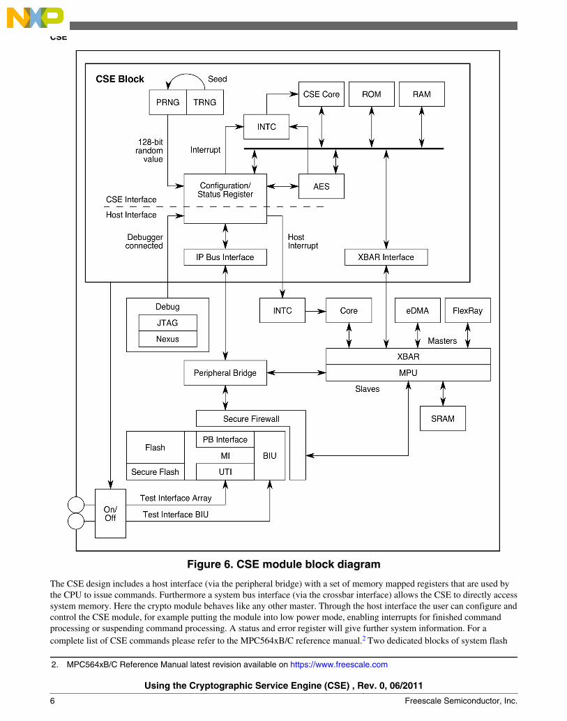
Figure 6. CSE module block diagram
The CSE design includes a host interface (via the peripheral bridge) with a set of memory mapped registers that are used bythe CPU to issue commands. Furthermore a system bus interface (via the crossbar interface) allows the CSE to directly accesssystem memory. Here the crypto module behaves like any other master. Through the host interface the user can configure andcontrol the CSE module, for example putting the module into low power mode, enabling interrupts for finished commandprocessing or suspending command processing. A status and error register will give further system information. For acomplete list of CSE commands please refer to the MPC564xB/C reference manual.2 Two dedicated blocks of system flash
2. MPC564xB/C Reference Manual latest revision available on https://www.freescale.com
CSE
Using the Cryptographic Service Engine (CSE) , Rev. 0, 06/2011
6 Freescale Semiconductor, Inc.
memory are used by the CSE for secure key and firmware storage. These blocks are not accessible by other masters from thesystem and therefore are called secure flash. The command processing is done by a 32-bit CSE core with attached ROM andRAM running at system frequency of the SoC. After system boot, the core comes out of reset and executes reset code fromthe module ROM. This code will load the firmware from the secure flash into the module RAM and start executing fromthere. This reduces the flash accesses by the crypto core.
The AES block is a slave to the crypto internal bus. It processes the encryption (plaintext→ ciphertext) and decryption(ciphertext→ plaintext) and offers AES CMAC authentication.
The random number generator includes a pseudo number generator (PRNG) and a true number generator (TRNG) for seedgeneration. The SHE specification defines that the seed value needs to be recalculated before random numbers can berequested, i.e. in worst-case scenarios it is written on every power cycle/reset. In addition to the capabilities demanded by theSHE specification CSE also supports using the TRNG independently of seed generation.
CSE controls external access to the secure flash via a test interface. When a part comes from the factory the test interface isstill open and is only closed after the user programs one or more user keys. The test interface will be re-opened only if thepart is reset to its factory state using the DEBUG CHALLENGE/AUTHORIZATION sequence. See Appendix C: Resettingthe secure flash to it’s factory State.
2.1 CSE featuresThe CSE implements a comprehensive set of cryptographic functions including secure key storage, AES encryption, secureboot, AES CMAC authentication and random number generation. As an introduction to the user these features are explainedin the following sections. This introduction is intended to give a basic understanding of the features and with the demo codesupplied with this application note facilitates the first steps with the CSE module itself. To get a more detailed overview ofthe register set please refer to the MPC564xB/C Reference Manual available at https://www.freescale.com.
CSE
Using the Cryptographic Service Engine (CSE) , Rev. 0, 06/2011
Freescale Semiconductor, Inc. 7
2.2 Details of contents of secure flash
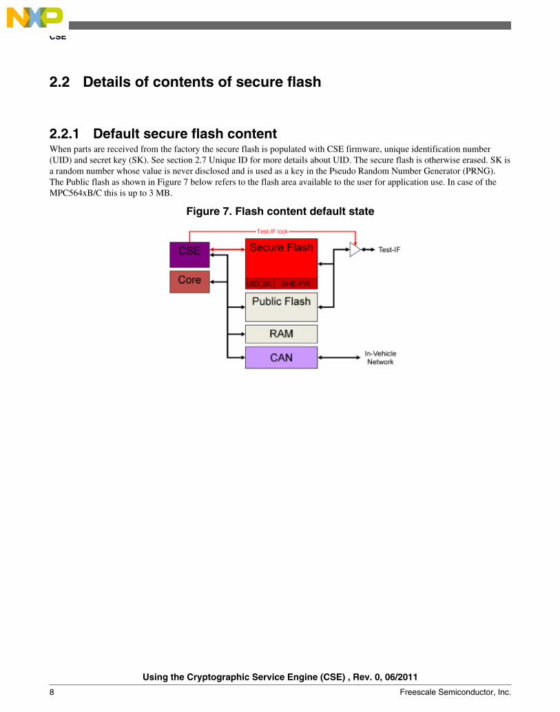
2.2.1 Default secure flash contentWhen parts are received from the factory the secure flash is populated with CSE firmware, unique identification number(UID) and secret key (SK). See section 2.7 Unique ID for more details about UID. The secure flash is otherwise erased. SK isa random number whose value is never disclosed and is used as a key in the Pseudo Random Number Generator (PRNG).The Public flash as shown in Figure 7 below refers to the flash area available to the user for application use. In case of theMPC564xB/C this is up to 3 MB.
Figure 7. Flash content default state
CSE
Using the Cryptographic Service Engine (CSE) , Rev. 0, 06/2011
8 Freescale Semiconductor, Inc.
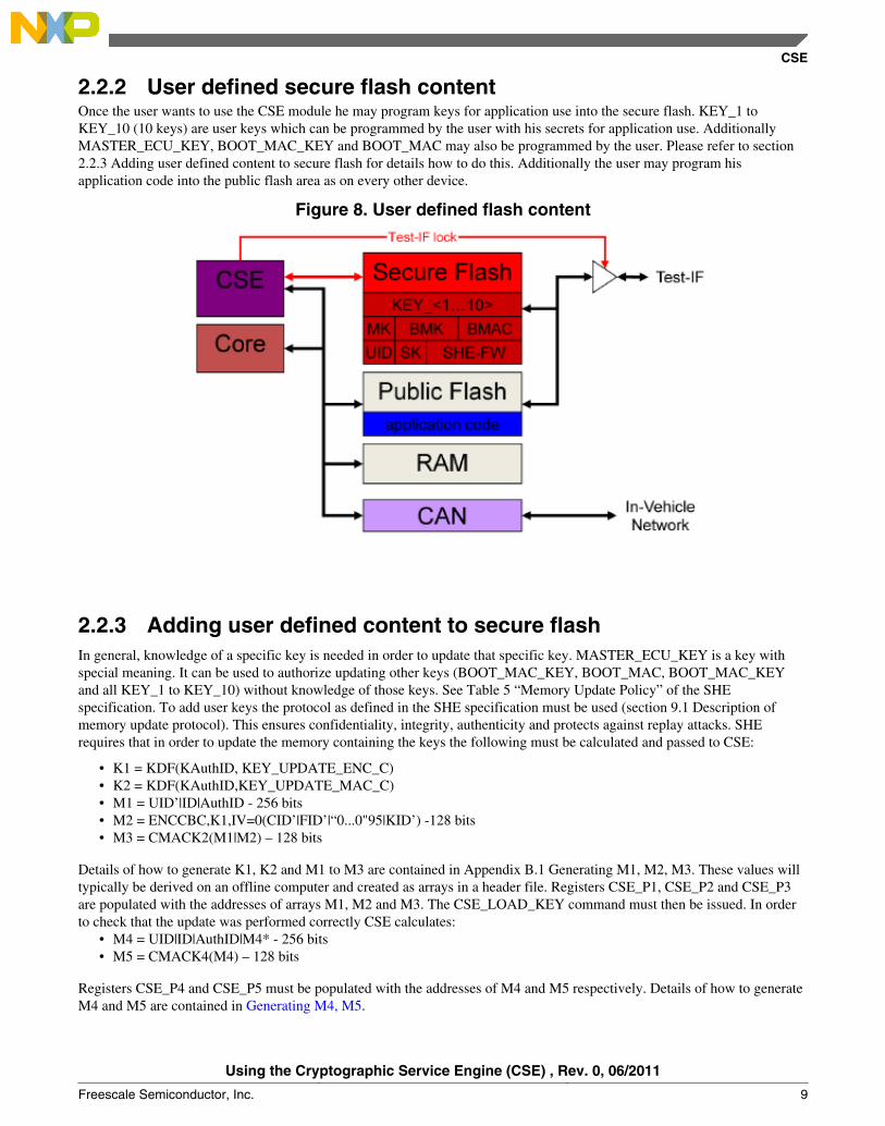
2.2.2 User defined secure flash contentOnce the user wants to use the CSE module he may program keys for application use into the secure flash. KEY_1 toKEY_10 (10 keys) are user keys which can be programmed by the user with his secrets for application use. AdditionallyMASTER_ECU_KEY, BOOT_MAC_KEY and BOOT_MAC may also be programmed by the user. Please refer to section2.2.3 Adding user defined content to secure flash for details how to do this. Additionally the user may program hisapplication code into the public flash area as on every other device.
Figure 8. User defined flash content
2.2.3 Adding user defined content to secure flashIn general, knowledge of a specific key is needed in order to update that specific key. MASTER_ECU_KEY is a key withspecial meaning. It can be used to authorize updating other keys (BOOT_MAC_KEY, BOOT_MAC, BOOT_MAC_KEYand all KEY_1 to KEY_10) without knowledge of those keys. See Table 5 “Memory Update Policy” of the SHEspecification. To add user keys the protocol as defined in the SHE specification must be used (section 9.1 Description ofmemory update protocol). This ensures confidentiality, integrity, authenticity and protects against replay attacks. SHErequires that in order to update the memory containing the keys the following must be calculated and passed to CSE:
• K1 = KDF(KAuthID, KEY_UPDATE_ENC_C)• K2 = KDF(KAuthID,KEY_UPDATE_MAC_C)• M1 = UID’|ID|AuthID - 256 bits• M2 = ENCCBC,K1,IV=0(CID’|FID’|“0...0"95|KID’) -128 bits• M3 = CMACK2(M1|M2) – 128 bits
Details of how to generate K1, K2 and M1 to M3 are contained in Appendix B.1 Generating M1, M2, M3. These values willtypically be derived on an offline computer and created as arrays in a header file. Registers CSE_P1, CSE_P2 and CSE_P3are populated with the addresses of arrays M1, M2 and M3. The CSE_LOAD_KEY command must then be issued. In orderto check that the update was performed correctly CSE calculates:
• M4 = UID|ID|AuthID|M4* - 256 bits• M5 = CMACK4(M4) – 128 bits
Registers CSE_P4 and CSE_P5 must be populated with the addresses of M4 and M5 respectively. Details of how to generateM4 and M5 are contained in Generating M4, M5.
CSE
Using the Cryptographic Service Engine (CSE) , Rev. 0, 06/2011
Freescale Semiconductor, Inc. 9
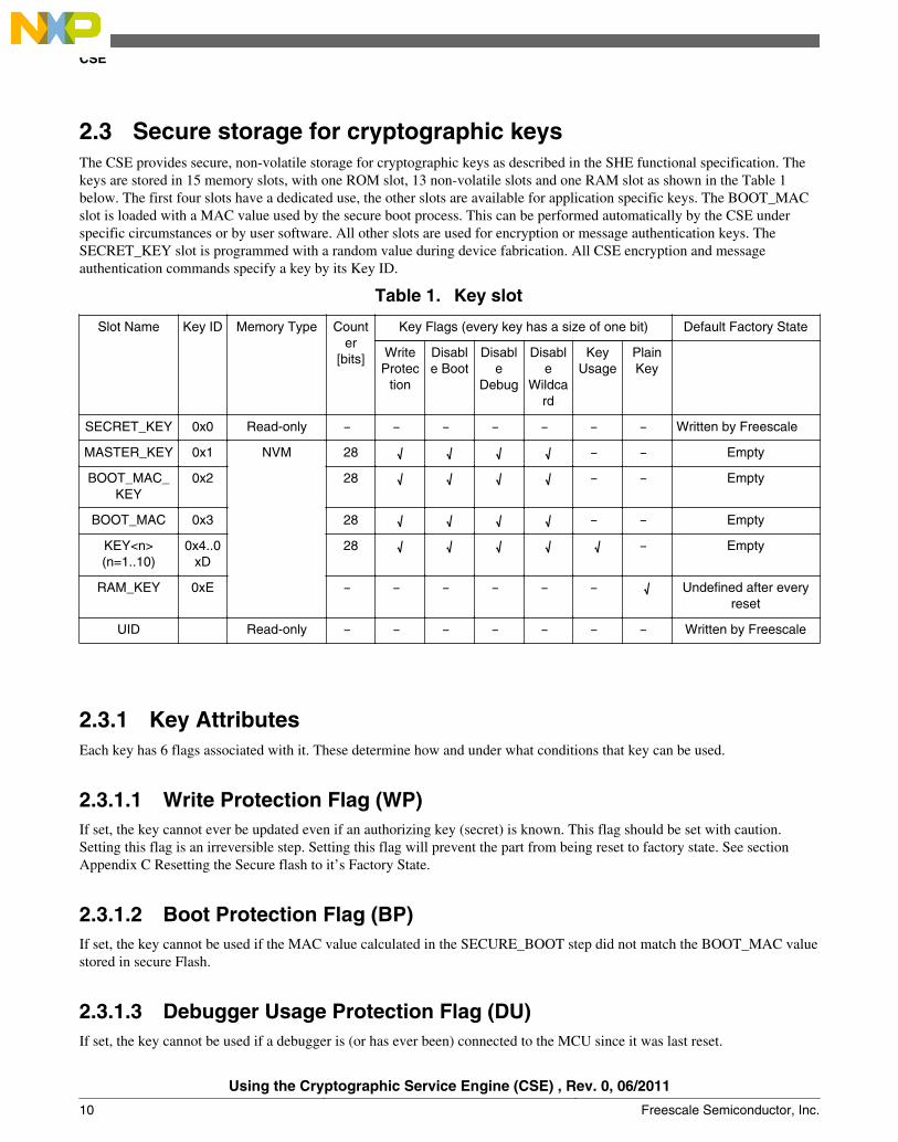
2.3 Secure storage for cryptographic keysThe CSE provides secure, non-volatile storage for cryptographic keys as described in the SHE functional specification. Thekeys are stored in 15 memory slots, with one ROM slot, 13 non-volatile slots and one RAM slot as shown in the Table 1below. The first four slots have a dedicated use, the other slots are available for application specific keys. The BOOT_MACslot is loaded with a MAC value used by the secure boot process. This can be performed automatically by the CSE underspecific circumstances or by user software. All other slots are used for encryption or message authentication keys. TheSECRET_KEY slot is programmed with a random value during device fabrication. All CSE encryption and messageauthentication commands specify a key by its Key ID.
Table 1. Key slot
Slot Name Key ID Memory Type Counter
[bits]
Key Flags (every key has a size of one bit) Default Factory State
WriteProtec
tion
Disable Boot
Disable
Debug
Disable
Wildcard
KeyUsage
PlainKey
SECRET_KEY 0x0 Read-only ̶ ̶ ̶ ̶ ̶ ̶ ̶ Written by Freescale
MASTER_KEY 0x1 NVM 28 √ √ √ √ ̶ ̶ Empty
BOOT_MAC_KEY
0x2 28 √ √ √ √ ̶ ̶ Empty
BOOT_MAC 0x3 28 √ √ √ √ ̶ ̶ Empty
KEY<n>(n=1..10)
0x4..0xD
28 √ √ √ √ √ ̶ Empty
RAM_KEY 0xE ̶ ̶ ̶ ̶ ̶ ̶ √ Undefined after everyreset
UID Read-only ̶ ̶ ̶ ̶ ̶ ̶ ̶ Written by Freescale
2.3.1 Key AttributesEach key has 6 flags associated with it. These determine how and under what conditions that key can be used.
2.3.1.1 Write Protection Flag (WP)If set, the key cannot ever be updated even if an authorizing key (secret) is known. This flag should be set with caution.Setting this flag is an irreversible step. Setting this flag will prevent the part from being reset to factory state. See sectionAppendix C Resetting the Secure flash to it’s Factory State.
2.3.1.2 Boot Protection Flag (BP)If set, the key cannot be used if the MAC value calculated in the SECURE_BOOT step did not match the BOOT_MAC valuestored in secure Flash.
2.3.1.3 Debugger Usage Protection Flag (DU)If set, the key cannot be used if a debugger is (or has ever been) connected to the MCU since it was last reset.
CSE
Using the Cryptographic Service Engine (CSE) , Rev. 0, 06/2011
10 Freescale Semiconductor, Inc.
2.3.1.4 Wildcard Protection Flag (WC)If set, the key cannot be updated using by supplying a special wildcard (UID=0).
2.3.1.5 Key Usage Flag (KU)This flag determines if a key can be used for encryption/decryption or for MAC generation/verification (CMAC). If the flagis set, the key is used for MAC generation/verification. If the flag is clear, the key is used for encryption.
2.3.2 Key CounterEach user key has a counter which must be increased on every update. The counter is 28 bits long. The new counter value isused in the derivation of M2 when a key is being updated. See Generate M2.
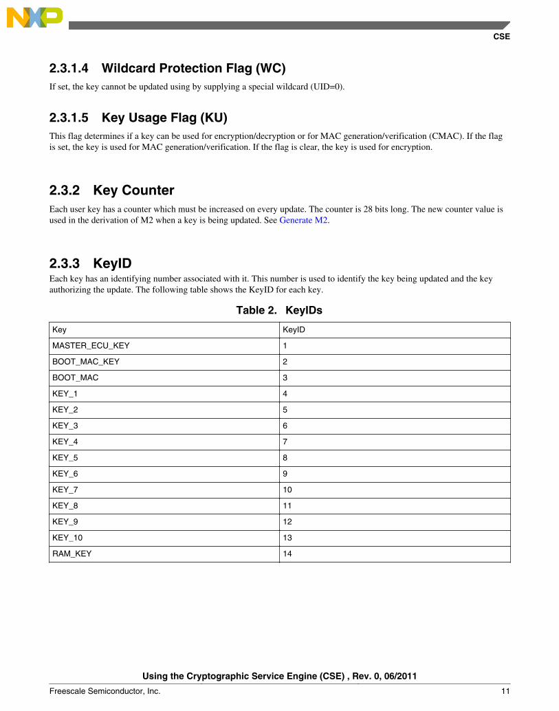
2.3.3 KeyIDEach key has an identifying number associated with it. This number is used to identify the key being updated and the keyauthorizing the update. The following table shows the KeyID for each key.
Table 2. KeyIDs
Key KeyID
MASTER_ECU_KEY 1
BOOT_MAC_KEY 2
BOOT_MAC 3
KEY_1 4
KEY_2 5
KEY_3 6
KEY_4 7
KEY_5 8
KEY_6 9
KEY_7 10
KEY_8 11
KEY_9 12
KEY_10 13
RAM_KEY 14
CSE
Using the Cryptographic Service Engine (CSE) , Rev. 0, 06/2011
Freescale Semiconductor, Inc. 11
2.4 AES-128 encryption and decryptionThe CSE supports AES-128 encryption and decryption in ECB (Electronic Codebook) and CBC (Cipher Block Chaining)modes of operation as described in chapter 1. The key is selected from one of the memory slots which must be enabled forthe encryption (KU =0; see section 2.3.1 Key Attributes). A plain text key can be loaded into the RAM_KEY slot using theLOAD_PLAIN_KEY command for keys that are not stored in a non-volatile memory slot. However, as this method implies apotential security risk, this might only be useful for development or debug purposes only.
2.5 AES-128 CMAC authenticationThe CSE uses the AES-128 CMAC algorithm for message authentication. The key for the CMAC operation is selected fromone of the memory slots which must be enabled for the authentication (KU =1; see section 2.3.1 Key Attributes). A plain textkey can be loaded into the RAM_KEY slot using the LOAD_PLAIN_KEY command for keys that are not stored in a non-volatile memory slot. The VERIFY_MAC command supports comparison of a calculated MAC with an input MAC value.
2.6 Random number generationThe CSE has both a Pseudo Random Number Generator (PRNG) and a True Random Number Generator (TRNG). ThePRNG has a 128-bit state variable and uses AES in output feedback mode to generate pseudo random values. A key derivedfrom the SECRET_KEY is used for the PRNG. The RND command updates the state of the PRNG and returns the 128-bitrandom value. The EXTEND_SEED command can be used to add entropy to the PRNG state. The PRNG state is initializedafter each reset with the INIT_RNG command which uses the TRNG to generate a 128-bit seed value for the PRNG. TheCSE_SR[RIN] flag is set when the PRNG is initialized. The INIT_RNG and TRNG_RND commands use the TRNG togenerate truly random values. The TRNG hardware runs off of a slower clock derived from the system clock. TheCSE_CR[DIV] field needs to be configured for these commands such that the TRNG clock is between 500 kHz and 2 MHz.Random values generated by the TRNG are checked with a statistical test to verify proper operation of the TRNG. If the testfails, a TRNG error (EC=0x12) is returned. Due to the statistical nature of this test, there is a very small probability (<10-9)that a properly operating TRNG will return an error. If an TRNG error is returned, the command can be issued again.
2.7 Unique IDUnique Identifier Number (UID) is unique for every part and is programmed into the secure flash when it is tested in waferform. UID is 120 bits long. UID can be used during inter ECU communications to confirm that external controllers have notbeen substituted. If Wildcard is disabled for a specific key, then that key cannot be updated without specific knowledge of theUID of the part being updated. See Section 2.3.1 Key Attributes. UID is also used in the process for resetting part to theirfactory state. See Appendix C: Resetting the Secure Flash to it’s Factory State.
UID can be obtained by issuing the CSE_GET_UID command.
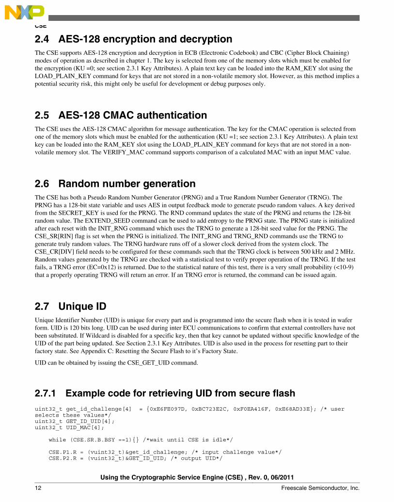
2.7.1 Example code for retrieving UID from secure flashuint32_t get_id_challenge[4] = {0xE6FE097D, 0xBC723E2C, 0xF0EA416F, 0xE68AD33E}; /* user selects these values*/uint32_t GET_ID_UID[4];uint32_t UID_MAC[4];
while (CSE.SR.B.BSY ==1){} /*wait until CSE is idle*/
CSE.P1.R = (vuint32_t)&get_id_challenge; /* input challenge value*/ CSE.P2.R = (vuint32_t)&GET_ID_UID; /* output UID*/
CSE
Using the Cryptographic Service Engine (CSE) , Rev. 0, 06/2011
12 Freescale Semiconductor, Inc.
CSE.P3.R = 0; CSE.P4.R = (vuint32_t)&UID_MAC; /* output challenge response */ CSE.CMD.R= CSE_GET_ID;
The CSE will return 0 if the MASTER_ECU_KEY is empty. UID_MAC is populated with a 128-bit MAC calculated overthe concatenation of a 128-bit input challenge value, UID and CSE_SR[24:31]. GET_ID_UID is 128 bits with the 8 leastsignificant bits set to 0.
2.8 Updating user keysAfter a part's user keys are programmed into the secure flash and the part is no longer in it's factory state, it may be necessaryto update one or more keys. SHE describes a mechanism for doing this and this has been implemented in the CSE module viathe CSE_LOAD_KEY command. If a key has Write Protection set, it will no longer be possible to update that key.
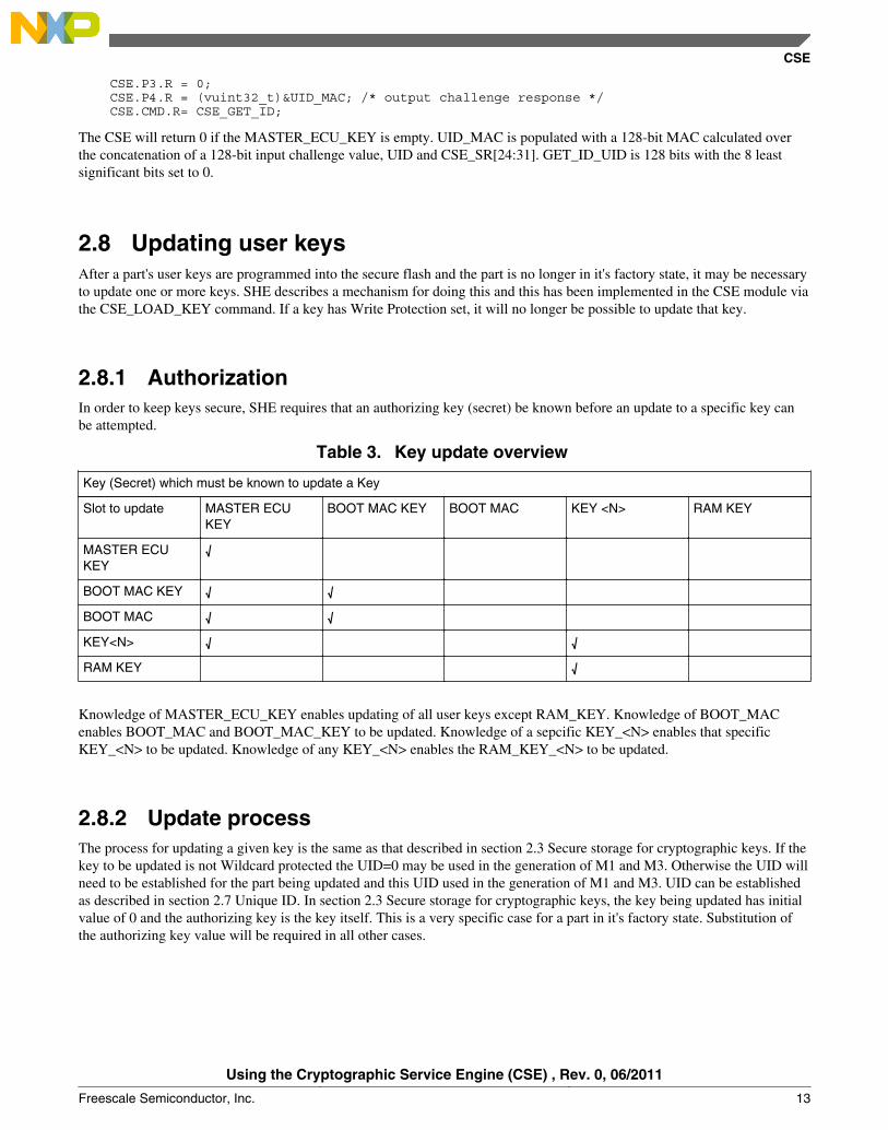
2.8.1 AuthorizationIn order to keep keys secure, SHE requires that an authorizing key (secret) be known before an update to a specific key canbe attempted.
Table 3. Key update overview
Key (Secret) which must be known to update a Key
Slot to update MASTER ECUKEY
BOOT MAC KEY BOOT MAC KEY <N> RAM KEY
MASTER ECUKEY
√
BOOT MAC KEY √ √
BOOT MAC √ √
KEY<N> √ √
RAM KEY √
Knowledge of MASTER_ECU_KEY enables updating of all user keys except RAM_KEY. Knowledge of BOOT_MACenables BOOT_MAC and BOOT_MAC_KEY to be updated. Knowledge of a sepcific KEY_<N> enables that specificKEY_<N> to be updated. Knowledge of any KEY_<N> enables the RAM_KEY_<N> to be updated.
2.8.2 Update processThe process for updating a given key is the same as that described in section 2.3 Secure storage for cryptographic keys. If thekey to be updated is not Wildcard protected the UID=0 may be used in the generation of M1 and M3. Otherwise the UID willneed to be established for the part being updated and this UID used in the generation of M1 and M3. UID can be establishedas described in section 2.7 Unique ID. In section 2.3 Secure storage for cryptographic keys, the key being updated has initialvalue of 0 and the authorizing key is the key itself. This is a very specific case for a part in it's factory state. Substitution ofthe authorizing key value will be required in all other cases.
CSE
Using the Cryptographic Service Engine (CSE) , Rev. 0, 06/2011
Freescale Semiconductor, Inc. 13
2.8.3 Erasing all keysA procedure for erasing the user content of the secure flash is described in Appendix C Resetting the secure flash to itsfactory state.
2.9 Secure Boot
2.9.1 Authenticating Boot CodeCSE has a mechanism which allows users to authenticate boot code in flash. The MCU can be configured so that on everyboot a section of code is authenticated and the generated MAC will be compared with a value previously stored in Secureflash. This is supported only for flash boot modes. It is not supported for other boot modes (serial download, wakeup toRAM) as this may present a potential security issue.
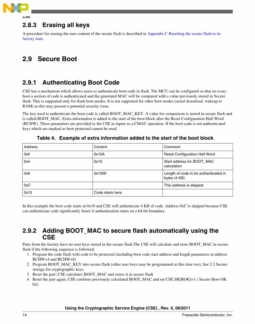
The key used to authenticate the boot code is called BOOT_MAC_KEY. A value for comparison is stored in secure flash andis called BOOT_MAC. Extra information is added to the start of the boot block after the Reset Configuration Half Word(RCHW). These parameters are provided to the CSE as inputs to a CMAC operation. If the boot code is not authenticatedkeys which are marked as boot protected cannot be used.
Table 4. Example of extra information added to the start of the boot block
Address Content Comment
0x0 0x15A Reset Configuration Half Word
0x4 0x10 Start address for BOOT_MACcalculation
0x8 0x1000 Length of code to be authenticated inbytes (4 KB)
0xC This address is skipped
0x10 Code starts here
In this example the boot code starts at 0x10 and CSE will authenticate 4 KB of code. Address 0xC is skipped because CSEcan authenticate code significantly faster if authentication starts on a 64-bit boundary.
2.9.2 Adding BOOT_MAC to secure flash automatically using theCSE
Parts from the factory have no user keys stored in the secure flash.The CSE will calculate and store BOOT_MAC in secureflash if the following sequence is followed:
1. Program the code flash with code to be protected (including boot code start address and length parameters at addressRCHW+4 and RCHW+8)
2. Program BOOT_MAC_KEY into secure flash (other user keys may be programmed at this time too), See 2.3 Securestorage for cryptographic keys.
3. Reset the part; CSE calculates BOOT_MAC and stores it in secure flash4. Reset the part again; CSE confirms previously calculated BOOT_MAC and set CSE.SR[BOK]=1 ( Secure Boot OK
bit)
CSE
Using the Cryptographic Service Engine (CSE) , Rev. 0, 06/2011
14 Freescale Semiconductor, Inc.
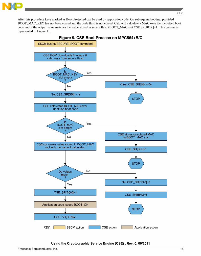
After this procedure keys marked as Boot Protected can be used by application code. On subsequent booting, providedBOOT_MAC_KEY has not been erased and the code flash is not erased, CSE will calculate a MAC over the identified bootcode and if the output value matches the value stored in secure flash (BOOT_MAC) set CSE.SR[BOK]=1. This process isrepresented in Figure 11.
Figure 9. CSE Boot Process on MPC564xB/C
CSE
Using the Cryptographic Service Engine (CSE) , Rev. 0, 06/2011
Freescale Semiconductor, Inc. 15
2.10 Code flash update procedureDuring software development and at other times during an ECU’s life cycle it may be necessary to change the code flashwhich is authenticated by the BOOT_MAC. This means that the BOOT_MAC calculated by the CSE will not match theBOOT_MAC stored in the secure flash. In this scenario cryptographic services which used keys marked as Boot Protectedwill be unavailable. The BOOT_MAC stored in secure flash must be updated to avoid this situation. There are 2 scenarioswhich lead to different methods for updating the stored BOOT_MAC.
2.10.1 Scenario 1: No key is write protected and all user keys can beerased and re-programmed
In this case the DEBUG_CHAL and DEBUG_AUTH commands can be used to set the secure flash back to its factory state.See Appendix C Resetting the Secure flash to it’s Factory State. The DEBUG_CHAL and DEBUG_AUTH commands willonly work on a part which has no keys marked as Write Protected. All user keys must be known in this scenario, as they willall be erased by this process and one must know them in order to restore them to their previous values. After successfullyrunning the DEBUG_CHAL and DEBUG_AUTH commands, the user keys section of the secure flash will be erased. Newkeys can be programmed into the secure flash as described in 2.3 Secure storage for cryptographic keys. The procedurewhich causes the CSE to generate BOOT_MAC should be followed. See Adding BOOT_MAC to secure flash automaticallyusing the CSE .
NOTE
The values at RCHW+4 (contains start address for BOOT_MAC) and RCHW+8 (contains BOOT_MAC code length inbytes) must be populated correctly.
2.10.2 Scenario 2: One or more keys is write protected and all userkeys cannot be erased. (or not all user keys are known)
In this case the DEBUG_CHAL and DEBUG_AUTH commands cannot be used to set the secure flash back to its factorystate. In order to update the BOOT_MAC a new value for it must be derived and the key updated as described in section 2.8Updating User Keys.
There are 2 methods which can be used to derive the new BOOT_MAC. These are described in the following sections.
2.10.2.1 Mehod 1 : Use the LOAD_RAM_KEY command and use the CSEto generate the new BOOT_MAC
In this method the RAM key is loaded by issuing the CSE_LOAD_PLAIN_KEY command. The CSE_GENERATE_MACcommand can be used to derive the new BOOT_MAC. If the code flash has already been programmed the following codecan be used to derive the new BOOT_MAC value.
#define BOOT_BLOCK_START_ADDR 0; volatile unsigned long long length ; vuint32_t * code_start_ptr; vuint32_t * code_length_ptr; vuint32_t * boot_block_ptr; boot_block_ptr = (uint32_t * )BOOT_BLOCK_START_ADDR ; code_start_ptr = boot_block_ptr + 1; /* get the code start address from the code flash*/ code_length_ptr = boot_block_ptr + 2; /* get the code length in bytes from the code flash*/
CSE
Using the Cryptographic Service Engine (CSE) , Rev. 0, 06/2011
16 Freescale Semiconductor, Inc.

length = (*code_length_ptr) * 8; /* CSE_GENERATE_MAC takes bits as its input */
CSE.P1.R = (uint32_t) &BOOT_MAC_KEY; CSE.CMD.R= CSE_LOAD_PLAIN_KEY; /* Load the BOOT_MAC_KEY as plain text to the RAM_KEY*/ if (CSE.ECR.R != CSE_NO_ERR) {failcount++;}
while (CSE.SR.B.BSY ==1){} /*wait until CSE is idle*/
CSE.P1.R = CSE_RAM_KEY; /* RAM key */ CSE.P2.R = (unsigned long long)&length; /* msg length */ CSE.P3.R = (vuint32_t)*code_start_ptr; CSE.P4.R = (vuint32_t)&NEW_BOOT_MAC; CSE.CMD.R= CSE_GENERATE_MAC; /* generate the new BOOT_MAC value*/
The new BOOT_MAC value can be used to update the BOOT_MAC values stored in secure flash.
2.10.2.2 Method 2 : Generate the new BOOT_MAC offlineIn this method an external program must be used. The hex data for binary image should be input to a program which cancalculate a new BOOT_MAC value using the BOOT_MAC_KEY. The new BOOT_MAC value can be used to update theBOOT_MAC values stored in secure flash.
2.11 CSE Run ModesOn MPC564xB/C two run modes are supported. These control wether the main core of the MPC564xB/C (called e200z4core) is gated by the CSE in flash boot modes.
2.11.1 Parallel Run ModeIn parallel run mode the e200z4 core is released in parallel to the CSE. The SECURE_BOOT command is executed by theCSE in parallel to the e200z4 booting.
In this run mode the system frequency can be changed to 120 Mhz without interrupting the CSE. Because of this, this mode istypically much faster at authenticating code than sequential mode, for e.g., 128 KB of code can be authenticated in 4.8 ms.
2.11.2 Sequential Run ModeIn sequential Run mode the e200z4 core is released after CSE has executed the SECURE_BOOT command . The e200z4core is clock gated by system logic until the SECURE_BOOT command has been completed by the CSE. A timeoutmechanism (set in hardware to 16M x 16Mhz IRC clocks =~ 1 second) prevents a CSE execution error from preventingsystem boot. In this Run mode the system frequency cannot be changed from the default 16 MHz IRC . Because of this, thismode is much slower at authenticating code than sequential mode for e.g., 128 KB of code can be authenticated in 25 ms.
2.11.3 Changing between Parallel and Sequential modesParts leaving the factory will have the CSE Run mode set to parallel by default. The shadow flash at the locations notedbelow are erased.
CSE
Using the Cryptographic Service Engine (CSE) , Rev. 0, 06/2011
Freescale Semiconductor, Inc. 17
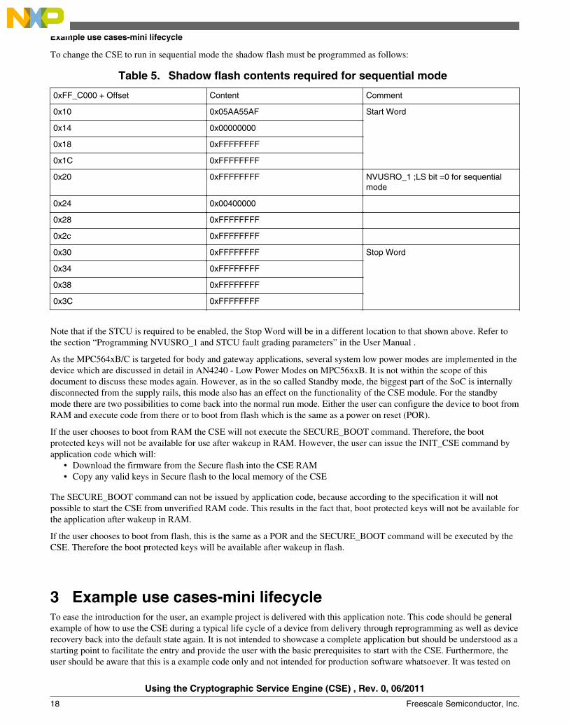
To change the CSE to run in sequential mode the shadow flash must be programmed as follows:
Table 5. Shadow flash contents required for sequential mode
0xFF_C000 + Offset Content Comment
0x10 0x05AA55AF Start Word
0x14 0x00000000
0x18 0xFFFFFFFF
0x1C 0xFFFFFFFF
0x20 0xFFFFFFFF NVUSRO_1 ;LS bit =0 for sequentialmode
0x24 0x00400000
0x28 0xFFFFFFFF
0x2c 0xFFFFFFFF
0x30 0xFFFFFFFF Stop Word
0x34 0xFFFFFFFF
0x38 0xFFFFFFFF
0x3C 0xFFFFFFFF
Note that if the STCU is required to be enabled, the Stop Word will be in a different location to that shown above. Refer tothe section “Programming NVUSRO_1 and STCU fault grading parameters” in the User Manual .
As the MPC564xB/C is targeted for body and gateway applications, several system low power modes are implemented in thedevice which are discussed in detail in AN4240 - Low Power Modes on MPC56xxB. It is not within the scope of thisdocument to discuss these modes again. However, as in the so called Standby mode, the biggest part of the SoC is internallydisconnected from the supply rails, this mode also has an effect on the functionality of the CSE module. For the standbymode there are two possibilities to come back into the normal run mode. Either the user can configure the device to boot fromRAM and execute code from there or to boot from flash which is the same as a power on reset (POR).
If the user chooses to boot from RAM the CSE will not execute the SECURE_BOOT command. Therefore, the bootprotected keys will not be available for use after wakeup in RAM. However, the user can issue the INIT_CSE command byapplication code which will:
• Download the firmware from the Secure flash into the CSE RAM• Copy any valid keys in Secure flash to the local memory of the CSE
The SECURE_BOOT command can not be issued by application code, because according to the specification it will notpossible to start the CSE from unverified RAM code. This results in the fact that, boot protected keys will not be available forthe application after wakeup in RAM.
If the user chooses to boot from flash, this is the same as a POR and the SECURE_BOOT command will be executed by theCSE. Therefore the boot protected keys will be available after wakeup in flash.
3 Example use cases-mini lifecycleTo ease the introduction for the user, an example project is delivered with this application note. This code should be generalexample of how to use the CSE during a typical life cycle of a device from delivery through reprogramming as well as devicerecovery back into the default state again. It is not intended to showcase a complete application but should be understood as astarting point to facilitate the entry and provide the user with the basic prerequisites to start with the CSE. Furthermore, theuser should be aware that this is a example code only and not intended for production software whatsoever. It was tested on
Example use cases-mini lifecycle
Using the Cryptographic Service Engine (CSE) , Rev. 0, 06/2011
18 Freescale Semiconductor, Inc.
the MPC56xx Freescale evaluation motherboard with a MPC5646xB/C 208LQFP daughter card. The example projectcontains several use cases. The project is using the GHS compiler 5.1.7 and Lauterbach debugger. The software concept ofthe single examples is described on a case by case basis in Appendix D.
4 ConclusionBy showing the reasons for cryptography in general, and example automotive security use-cases the need for cryptographybecomes obvious. To protect the cryptographic keys from software attacks, the control over those keys moved from thesoftware domain to the hardware domain. The MPC564xB/C device is now the first device in the Freescale portfolio offeringthe security features specified in the Secure Hardware Extension (SHE) functional specification completely in hardwareoffering a higher security standard to OEM’s in the future when using this device.
The discussions and explanations in this document provide an overview of the features the CSE module implements and howthese features can be used. With the example code simulating a mini-lifecycle from first silicon, over re-programming up tosetting everything back into the default state will give the reader the means to start working with this module. This iscomplemented with an explanatory video which can be found in the references.
For a more detailed discussion about how the CSE module can be used to protect application code please refer to applicationnote AN4235 - Using CSE to protect your application via a circle of trust.
5 GlossaryAES – Advanced Encryption Standard
CSE – Cryptograhpic Service Engine
CBC – Cipher Block Chaining
CFB – Cipher Feedback
CMAC – Cipher based message authentication code
CTR – Counter (cipher mode)
ECB – Electronic Codebook
GHS – Green Hills
OEM – Original Equipment Manufacturer
OFB – Output Feedback
POR – Power on Reset
PRNG – Pseudo Random Number Generator
RCHW – Reset Configuration Half Word
RNG – Random Number Generator
SHE – Secure Hardware Extension
SK – Secret Key
Conclusion
Using the Cryptographic Service Engine (CSE) , Rev. 0, 06/2011
Freescale Semiconductor, Inc. 19
6 ReferencesSHE - Secure Hardware Extension functional specification Version1.1 (rev 439) available on www.automotive-his.de
MPC564xB Reference Manual available on https://www.freescale.com
AN4240 - Low Power Modes on MPC56xxB available on https://www.freescale.com
AN4235 - Using CSE to protect your application via a circle of trust available on https://www.freescale.com
CSE encrypt/decrypt demo video - available from http://www.youtube.com/user/freescale
[FIPS197] NIST/FIPS: Announcing the Advanced Encryption Standard (AES); November 26, 2001; http://csrc.nist.gov/publications/fips/fips197/fips-197.pdf
Appendix A
A.1 AES algorithmThe Advanced Encryption Standard (AES) algorithm was selected and specified by the US National Institute of Standard andTechnology (NIST) [FIPS197] after a public championship. The designers of the algorithm are Joan Daemen and VincentRijmen. For this reason often the algorithm is called Rijndael-Algorithm.
References
Using the Cryptographic Service Engine (CSE) , Rev. 0, 06/2011
20 Freescale Semiconductor, Inc.
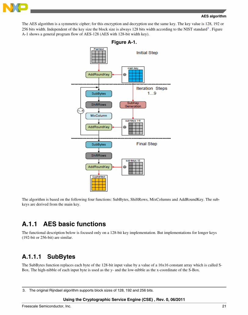
The AES algorithm is a symmetric cipher; for this encryption and decryption use the same key. The key value is 128, 192 or256 bits width. Independent of the key size the block size is always 128 bits width according to the NIST standard3 . FigureA-1 shows a general program flow of AES-128 (AES with 128-bit width key).
Figure A-1.
The algorithm is based on the following four functions: SubBytes, ShiftRows, MixColumns and AddRoundKey. The sub-keys are derived from the main key.
A.1.1 AES basic functionsThe functional description below is focused only on a 128-bit key implementation. But implementations for longer keys(192-bit or 256-bit) are similar.
A.1.1.1 SubBytesThe SubBytes function replaces each byte of the 128-bit input value by a value of a 16x16 constant array which is called S-Box. The high-nibble of each input byte is used as the y- and the low-nibble as the x-coordinate of the S-Box.
3. The original Rijndael algorithm supports block sizes of 128, 192 and 256 bits.
AES algorithm
Using the Cryptographic Service Engine (CSE) , Rev. 0, 06/2011
Freescale Semiconductor, Inc. 21

A.1.1.2 ShiftRowsThe ShiftRows function interprets the input value as an 4x4 array and rotates the second row by one, the third row by two andthe fourth row by 3 bytes to the left.
A.1.1.3 MixColumnsThe input values are interpreted again as a 4x4 array. Every column will be modulo multiplied with a predefined matrix.
A.1.1.4 AddRoundKeyThe 128-bit input value is xor’ed with the iteration specific sub-key value.
A.1.1.5 SubKey GenerationThe SubKeys are generated by allocating a 44x4 byte array as shown in Figure A-2.
Figure A-2. 44x4 key array
The first 4x4 block is filled up with the main key. The remaining cells are determined by the following two rules:
Rule #1: Columns where the index could be divided by 4 are calculated by the following:1. Rotate the column before (Wi-1) by one byte up.2. Replace the four byte values by the S-Box like in the SubBytes functions3. XOR the column with the column of a pre-defined matrix called Rcon.
Rule #2: All other columns are generated by xor-ing wi-1 with wi-4.
Appendix B
B.1 Memory Update Protocol
B.1.1 Generating M1, M2, M3In order to generate M1, M2 and M3 the following steps must be performed.
Using the Cryptographic Service Engine (CSE) , Rev. 0, 06/2011
22 Freescale Semiconductor, Inc.
B.1.2 Generate K1K1 = KDF(KAuthID, KEY_UPDATE_ENC_C)
• KDF is key derivation function which derives a secret key (K1) from a secret value.• KAuthID – Authorizing key value. In the case where a part from the factory has no keys programmed ( the Secure Flash
is erased) the value stored in flash does not have a valid checksum and CSE does not copy it to RAM at initialization,hence this value, in the CSE’s RAM, is zero. In this case we are using AuthID = ID (i.e. the authorizing key will be thekey itself)
• KEY_UPDATE_ENC_C – Constant value defined by SHE as:
0x01015348_45008000_00000000_000000B0
B.1.3 Generate K2K2 = KDF(KAuthID,KEY_UPDATE_MAC_C)
• KEY_UPDATE_MAC_C – Constant value defined by SHE as :
0x01025348_45008000_00000000_000000B0
B.1.4 Generate M1M1 = UID’|ID|AuthID
• AuthID can be either ID (number of key being updated) or MASTER_ECU_KEY number (0x1)• UID’ can be 0 (Wildcard value) because WC flag = 0 on parts from the factory• UID is 120 bit and ID and AuthID are 4 bits each
B.1.5 Generate M2M2 = ENCCBC,K1,IV=0(CID’|FID’|“0...0"95|KID’)
• Run a CBC encryption using K1 (as defined previously) with Initial Value (IV) =0• The message for encryption is a concatenation of:• CID - the new counter value (28 bits). 0x0000001 in this case• FID - New Protection flags - WP | BP | DP | KU | WC (5 bits)• 95 zeros to fill first 128 bit block with zeros• KID - The new key value (128 bits)
B.1.6 Generate M3M3 = CMACK2(M1|M2)
• A CMAC is performed over M1 and M2 using key K2
Memory Update Protocol
Using the Cryptographic Service Engine (CSE) , Rev. 0, 06/2011
Freescale Semiconductor, Inc. 23
B.1.7 Generating M4, M5When the CSE_LOAD_KEY command is issued CSE derives M4 and M5. These values can be independently generatedoffline and compared against those generated by the CSE.
B.1.8 Generating K3K3 = KDF(KEYID,KEY_UPDATE_ENC_C)
• KEY_UPDATE_ENC_C – Constant value defined by SHE as:
0x01025348_45008000_00000000_000000B0
B.1.9 Generate M4M4 = UID|ID|AuthID|M4*
• M4 is a concatenation of:• UID – Unique ID (120 bits)• ID – number of key updated (4 bits)• AuthID – number of key authorizing the update (4 bits)• M4* - the encrypted counter value; prior to encryption the counter value (28 bits) is padded with a 1 and 99 0’s.
The key for the ECB encryption is K3 (derived as above)
B.1.10 Generate M5M5 = CMACK4(M4)
• K4 = KDF (KEYID,KEY_UPDATE_MAC_C)
If M4 and M5 match to what was calculated offline and CSE returns NO_ERROR in the CSE_ECR (Error CodeRegister) then the LOAD_KEY command was successful.
NOTEIf a key has it’s Write Protect (WP) attribute set, the key cannot ever beupdated or erased. See Section 2.3.1 Key Attributes. Write Protection shouldonly be used when the user is absolutely certain that the key never needs to bechanged or erased. Setting Write Protection on any single key will mean thatthe part cannot be reset to its factory state using the DEBUG CHALLENGE/AUTHORIZATION sequence. See section Appendix C Resetting the Secureflash to it’s Factory State.
Memory Update Protocol
Using the Cryptographic Service Engine (CSE) , Rev. 0, 06/2011
24 Freescale Semiconductor, Inc.
B.2 Example code for updating a key (secret)uint32_t M1 [4] = {0xFFFFFFFF, 0xFFFFFFFF, 0xFFFFFFFF, 0xFFFFFF11};uint32_t M2 [8] = {0xff8b75f7, 0x3e6ad5a1, 0x729423c6, .. , 0xf0cc28ec};uint32_t M3 [4] = {0x57f51382, 0x4cfd1ba7, 0xd7593939, 0x4c8d0036};uint32_t M4_output [8] ;uint32_t M5_output [4] ;while (CSE.SR.B.BSY ==1){} /*wait until CSE is idle*/CSE.P1.R = (vuint32_t)&M1 ; /* address where CSE will look for M1*/CSE.P2.R = (vuint32_t)&M2 ; /* address where CSE will look for M2*/CSE.P3.R = (vuint32_t)&M3; /* address where CSE will look for M3*/CSE.P4.R = (vuint32_t)&M4_output; /* address where CSE will write M4*/CSE.P5.R = (vuint32_t)&M5_output; /* address where CSE will write M5*/CSE.CMD.R= CSE_LOAD_KEY;
Appendix C
C.1 Appendix C Resetting the secure flash to its factory stateSHE describes a mechanism for resetting the secure flash to the state it was in when it left the factory. The mechanism is onlyapplicable if no user key has been write protected. The process is described in section 11 of the SHE spec “failure analysis ofSHE/Resetting of SHE”. CSE has implemented this mechanism by way of 2 commands. These are CSE_DEBUG_CHAL andCSE_DEBUG_AUTH. Successfully issuing these commands will result in the part having no user keys (BOOT_MAC,BOOT_MAC_KEY, KEY1..KEY10 are all erased).
The TRNG must be initialized prior to the CSE_DEBUG_CHAL command being issued. The TRNG is initialized byexecuting the CSE_INIT_RNG command. The TRNG is used in deriving a challenge value. The CSE_CR[DIV] field needsto be configured for these commands such that the TRNG clock is between 500 kHz and 2 MHz.
/* set up DIVIDER for TRNG*/
CSE.CR.B.DIV = 29; /* for 120 Mhz Fsys - gives 2 Mhz TRNG clock*/
/* initialize RNG */
CSE.CMD.R= CSE_INIT_RNG;
The RIN bit must be checked to confirm that the TRNG was correctly initialized
if (CSE.SR.R & 0x00000020 != 0x00000020 ) {failcount++;} /* check RIN bit is set*/
The CSE will provide a challenge value when the CSE_DEBUG_CHAL command is issued.
/* generate challenge value */
CSE.P1.R = (vuint32_t)&challenge ; /* challenge is declared as 4 x uint32_t */
CSE.CMD.R= CSE_DEBUG_CHAL;
The UID for the part in question is added to challenge output and an authorization value is derived using KDEBUG
KDEBUG is defined as :• KDEBUG = KDF(MASTER_ECU_KEY ,DEBUG_KEY_C)
• DEBUG_KEY_C = 0x01035348_45008000_00000000_000000B0
• The authorization value is calculated as follows:
Example code for updating a key (secret)
Using the Cryptographic Service Engine (CSE) , Rev. 0, 06/2011
Freescale Semiconductor, Inc. 25
• AUTHORIZATION= CMACKDEBUG(CHALLENGE|UID)
• For development purposes this may be calculated using the CSE• /* load RAM_key with KDEBUG*/
CSE.P1.R = (uint32_t) &KDEBUG;CSE.CMD.R= CSE_LOAD_PLAIN_KEY;while (CSE.SR.B.BSY ==1){} /*wait until CSE is idle*/challenge_UID [0] = challenge[0];challenge_UID [1] = challenge[1];challenge_UID [2] = challenge[2];challenge_UID [3] = challenge[3];challenge_UID [4] = UID[0];challenge_UID [5] = UID[1];challenge_UID [6] = UID[2];challenge_UID [7] = UID[3];/* generate CMAC based on challenge|UID using KDEBUG */CSE.P1.R = CSE_RAM_KEY; /* RAM key */CSE.P2.R = (unsigned long long)&length; /* msg length : 248 in this case (UID is 120 bits )*/CSE.P3.R = (vuint32_t)&challenge_UID;CSE.P4.R = (vuint32_t)&authorization;CSE.CMD.R= CSE_GENERATE_MAC;
AUTHORIZATION is passed to CSE and CSE_DEBUG_AUTH is issued.
/* issue authorization command */CSE.P1.R = (vuint32_t)&authorization ;CSE.CMD.R = CSE_DEBUG_AUTH;
If the CSE_DEBUG_AUTH command is successfully executed, CSE will respond with CSE_NO_ERROR in CSE_ECR(error code register).
Appendix D
D.1 Example codeAll examples are running on a Freescale Evaluation board. Basic mode initialization of the part is done and the PLL is setupto run at 120 MHz. Examples A.1 to A.3 are running from RAM as they update the system or secure flash. The exampleprograms mentioned in A.4 are running from flash. The examples were tested using the GreenHills Compiler 5.1.7 and aLauterbach Debugger. In the folder called Lauterbach scripts, you can find toplevel *.cmm scripts with the same name as thetestcase. Use these scripts to run the examples. The main scripts usually call subscripts. These subscripts can also be runstandalone.
For the testcases a set of pre-calculated keys and values are used which are shown in the following table. These values can befound in some of the header files provided with the examples. To use user-defined keys the user needs to use offline scripts tocalculate the necessary values.
Using the Cryptographic Service Engine (CSE) , Rev. 0, 06/2011
26 Freescale Semiconductor, Inc.
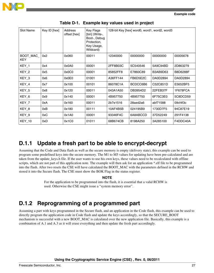
Table D-1. Example key values used in project
Slot Name Key ID [hex] Addressoffset [hex]
Key Flags[bin] (Write-,Boot-, DebugProtection,Key Usage,Wildcard)
128-bit Key [hex] word0, word1, word2, word3
BOOT_MAC_KEY
0x2 0x060 00011 12340000 00000000 00000000 00005678
KEY_1 0x4 0x0A0 00001 2FF8B03C 5C540546 5A9C94BD 2D863279
KEY_2 0x5 0x0C0 00001 85852FF8 E7860C89 B3AB9D63 B8D6288F
KEY_3 0x6 0x0E0 01001 A36FF144 FB6D5E2C DA0D2894 DA0D2894
KEY_4 0x7 0x100 00101 86078C1A BCDCC6B6 C52C851D E5652BF5
KEY_5 0x8 0x120 00011 043A1A50 DB3954D2 22FEB37F 1F678FCA
KEY_6 0x9 0x140 00001 4B957750 4B957750 6F75C3E0 5C8DCD59
KEY_7 0xA 0x160 00011 2b7e1516 28aed2a6 abf71588 09cf4f3c
KEY_8 0xB 0x180 00111 10AF4B5B 024195B9 1730D7F5 94C87E19
KEY_9 0xC 0x1A0 00001 93346F4C 6A8ABCCD 37D52249 291F4138
KEY_10 0xD 0x1C0 01011 68B674CB 8198A250 3A285100 F4DDC40A
D.1.1 Update a fresh part to be able to encrypt-decryptAssuming that the Code and Data flash as well as the secure memory is empty (delivery state), this example can be used toprogram some predefined keys into the secure memory. The M1 to M5 values for updating have been pre-calculated and aretaken from the update_keys.h file. If the user wants to use his own keys, these values need to be recalculated with offlinescripts, which are not part of this application note. The example will then ask for an application *.elf file to be programmedinto the flash. After two resets the CSE will have calculated the BOOT_MAC with the parameters defined in the RCHW andstored it into the Secure flash. The CSE must show the BOK Flag in the status register.
NOTEFor the application to be programmed into the flash, it is essential that a valid RCHW isused. Otherwise the CSE might issue a “system memory error”.
D.1.2 Reprogramming of a programmed partAssuming a part with keys programmed in the Secure flash, and an application in the Code flash, this example can be used todirectly program the application code in Code flash and update the keys accordingly, so that the SECURE_BOOTmechanism is successful with a new BOOT_MAC is calculated over the new application file. Basically, this example is acombination of A.1 and A.3 as it will erase everything and then update the fresh part accordingly.
Example code
Using the Cryptographic Service Engine (CSE) , Rev. 0, 06/2011
Freescale Semiconductor, Inc. 27
D.1.3 Recovery to default state againAssuming a part with keys programmed in the Secure flash and an application in the Code flash, this example can be used toget the part back into the delivery state. This means this example will erase all keys in the Secure flash with the debugchallenge and authorization protocol. It will also erase the Code and Data flash. The user is then able to start programmingagain.
D.1.4 Pin toggle test programsThere are two separate demo applications provided with the code. Both programs toggle an LED on the board and runstandalone from flash. The *.elf files are provided to have flash code with a valid RCHW configuration available for testingthe SECURE_BOOT mechanism with two different files. For first tests, it is recommended to use these files when promptedto program an *.elf file by the demo applications.
Z4_flash_Pin_Blink_VLE_standalone toggles LED1 on the EVB
Z4_flash_Pin_Blink2_VLE_standalone toggles LED3 on the EVB
Using the Cryptographic Service Engine (CSE) , Rev. 0, 06/2011
28 Freescale Semiconductor, Inc.
How to Reach Us:
Home Page:www.freescale.com
Web Support:http://www.freescale.com/support
USA/Europe or Locations Not Listed:Freescale SemiconductorTechnical Information Center, EL5162100 East Elliot RoadTempe, Arizona 85284+1-800-521-6274 or +1-480-768-2130www.freescale.com/support
Europe, Middle East, and Africa:Freescale Halbleiter Deutschland GmbHTechnical Information CenterSchatzbogen 781829 Muenchen, Germany+44 1296 380 456 (English)+46 8 52200080 (English)+49 89 92103 559 (German)+33 1 69 35 48 48 (French)www.freescale.com/support
Japan:Freescale Semiconductor Japan Ltd.HeadquartersARCO Tower 15F1-8-1, Shimo-Meguro, Meguro-ku,Tokyo 153-0064Japan0120 191014 or +81 3 5437 [email protected]
Asia/Pacific:Freescale Semiconductor China Ltd.Exchange Building 23FNo. 118 Jianguo RoadChaoyang DistrictBeijing 100022China+86 10 5879 [email protected]
For Literature Requests Only:Freescale Semiconductor Literature Distribution Center1-800-441-2447 or +1-303-675-2140Fax: [email protected]
Document Number: AN4234Rev. 0, 06/2011
Information in this document is provided solely to enable system and softwareimplementers to use Freescale Semiconductors products. There are no express or impliedcopyright licenses granted hereunder to design or fabricate any integrated circuits orintegrated circuits based on the information in this document.
Freescale Semiconductor reserves the right to make changes without further notice to anyproducts herein. Freescale Semiconductor makes no warranty, representation, orguarantee regarding the suitability of its products for any particular purpose, nor doesFreescale Semiconductor assume any liability arising out of the application or use of anyproduct or circuit, and specifically disclaims any liability, including without limitationconsequential or incidental damages. "Typical" parameters that may be provided inFreescale Semiconductor data sheets and/or specifications can and do vary in differentapplications and actual performance may vary over time. All operating parameters,including "Typicals", must be validated for each customer application by customer'stechnical experts. Freescale Semiconductor does not convey any license under its patentrights nor the rights of others. Freescale Semiconductor products are not designed,intended, or authorized for use as components in systems intended for surgical implantinto the body, or other applications intended to support or sustain life, or for any otherapplication in which failure of the Freescale Semiconductor product could create asituation where personal injury or death may occur. Should Buyer purchase or useFreescale Semiconductor products for any such unintended or unauthorized application,Buyer shall indemnify Freescale Semiconductor and its officers, employees, subsidiaries,affiliates, and distributors harmless against all claims, costs, damages, and expenses, andreasonable attorney fees arising out of, directly or indirectly, any claim of personal injuryor death associated with such unintended or unauthorized use, even if such claims allegesthat Freescale Semiconductor was negligent regarding the design or manufacture ofthe part.
RoHS-compliant and/or Pb-free versions of Freescale products have the functionality andelectrical characteristics as their non-RoHS-complaint and/or non-Pb-free counterparts.For further information, see http://www.freescale.com or contact your Freescalesales representative.
For information on Freescale's Environmental Products program, go tohttp://www.freescale.com/epp.
Freescale™ and the Freescale logo are trademarks of Freescale Semiconductor, Inc.All other product or service names are the property of their respective owners.
© 2011 Freescale Semiconductor, Inc.