using spice frequency domain data in ctle ami …...1. use the spice frequency domain data files to...
TRANSCRIPT

Using SPICE Frequency Domain Data in CTLE AMI Models 2012
Copyright © 2012 John Baprawski Page 1
Using SPICE Frequency Domain Data in CTLE AMI Models
Author: John Baprawski
Date: March 22, 2012
Introduction
High speed digital (HSD) integrated circuits (ICs) are used in Serializer/Deserializer (SerDes)
systems. In such systems, a lossy channel exists between the transmitter circuit and the
receiver circuit and at high data rates the received data stream is severely distorted and
requires reconstruction (equalization) before use. For system design, signal integrity (SI)
engineers often convert such circuits into Input/Output Buffer Information specification (IBIS)
models to achieve fast simulations for evaluation and performance prediction.
One common modeling objective is to use SPICE simulation data from analog transistor level
circuits to model a continuous time linear equalizer (CTLE) based on the IBIS Algorithmic Model
Interface (AMI). Such a CTLE model often has many defined states for use in the circuit. There
may be 10s, 100s or 1000s of states, each controlled by a digital word in the CTLE circuit.
This article will introduce the reader to an approach for modeling such an N-state CTLE as an
IBIS AMI model using SPICE frequency domain data. This article documents an example for a
4-state CTLE AMI model with its state controlled by integer value. The methodology discussed
is usable any number of CTLE states.
For a discussion on the basics of a CTLE, see the companion article from this author: “SerDes
System CTLE Basics”; http://www.johnbaprawski.com/2012/04/01/serdes-system-ctle-basics.
This article is an example on using the Agilent products SystemVue and ADS to generate C++
code and create a portable AMI model for an N-state CTLE.
The tools and files associated with this article are:
Advanced Design System (ADS) 2011.10
SystemVue 2011.10
Visual Studio 2008 SP1 (free Express Edition or Professional Edition)
NState_CTLE.zip archive file with this content:
Where

Using SPICE Frequency Domain Data in CTLE AMI Models 2012
Copyright © 2012 John Baprawski Page 2
AC_data is a directory containing the SPICE generated file for the N state CLTE frequency
domain responses.
AC_S_Param_data is a directory containing the S-Parameter files defining the N channels used
with the CTLEs.
AMI_System_wrk is an ADS 2011.10 workspace that demonstrates the use of the
Rx_NState_CTLE AMI model in the ADS Channel Simulator.
AMI_Tx_Rx_System is a Microsoft Visual Studio 2008 Solution generated by SystemVue that
contains the portable Rx_NState_CTLE AMI model.
Impulse_data is a directory containing the equivalent impulse responses for the CTLEs.
NState_CTLE is a Microsoft Visual Studio 2008 Solution containing the custom C++
NState_CTLE model based on the Impulse data and is used to generate the AMI model in
SystemVue.
AMI_Tx_Rx_System.wsv is a SystemVue workspace used to convert the custom NState_CTLE
SystemVue model into a portable Rx_NState_CTLE AMI model.
FD_to_TD.wsv is a SystemVue workspace used to convert the CTLE frequency domain data
into equivalent impulse responses.
This article and zip archive is available from the author’s web site at:
http://www.johnbaprawski.com/2012/04/08/using-spice-frequency-domain-data-in-ctle-ami-
models
For discussion purposes in this article, it is presumed that the content of this zip file are place in
the PC directory C:\AMI.
General SerDes System
Figure 1 shows a general SerDes system:
Figure 1. A general SerDes system
The typical SerDes system contains input data, serializer, transmitter (TX), channel, receiver (RX), deserializer and output data. The serial data bit stream is input to the transmitter. The transmitter consists of an equalizer (EQ) and a linear analog backend that includes packaging effects. The channel between the transmit backend and receiver front end consists of transmission lines (TL) that may include wiring and printed circuit board traces. The receiver

Using SPICE Frequency Domain Data in CTLE AMI Models 2012
Copyright © 2012 John Baprawski Page 3
front end includes packaging effects. The receiver contains signal processing with an EQ and clock and data recovery (CDR). Though the channel in real systems has multiple input and output pins, typically with differential input and output pin pairs, the discussion in this article is as a channel with a single ended input and output.
The Problem
The typical SerDes system channel is a linear system that contains high frequency attenuation of the transmitted signal. One specific SerDes system many need to work with many different system channels. Figure 2 shows a set of 4 SerDes channel characteristics in the frequency domain that is typical for channels. For discussion in this article, the data used with these channels has a 100 psec bit time (10 Gbps bit rate). The figure y-axis is in dB units.
Figure 2: Channel Attenuation vs Frequency
This set of curves is representative of any set of frequency domain channel characteristics. Most practical systems have characteristics that include a lot of irregularity due to system mismatches and signal suck-outs. This simplified set of curves is for discussion purposes in this article. The Nyquist frequency for the 10 Gbps data stream is 5 GHz. The channel attenuation at 5 GHz varies from -2.5 dB to -8 dB. This high frequency attenuation needs to be restored to a flat response within the Nyquist frequency band (0 – 5 GHz) to achieve low data bit error rates in the SerDes system. Though equalization is typically implemented in both the transmitter and in the receiver, for the purpose of discussion in this article, it will be assumed that all of the channel equalization will occur in the receiver using a Discrete Time Linear Equalizer (DLE) CTLE. For each channel characteristic, a DLE CTLE can be designed that restores the system
response to that for a defined reference channel. See the companion article “SerDes System
CTLE Basics” for such DLE CTLE design.
Using SPICE Frequency Domain Data in CTLE AMI Models 2012
Copyright © 2012 John Baprawski Page 4
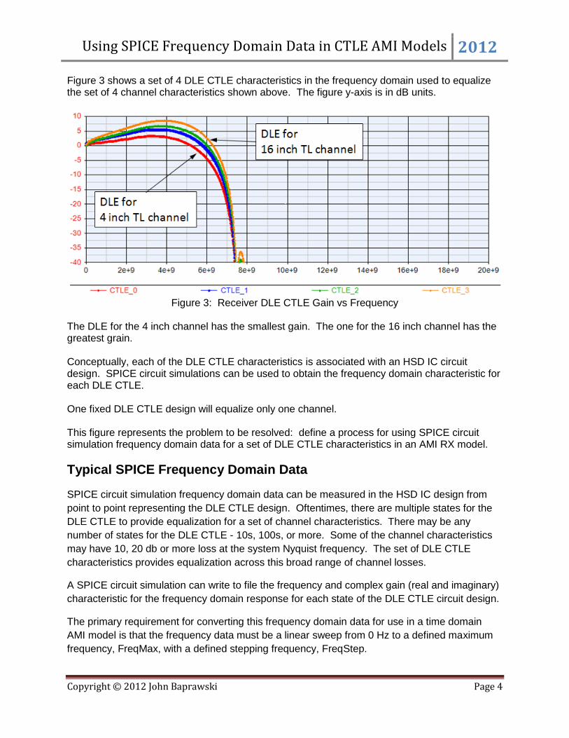
Figure 3 shows a set of 4 DLE CTLE characteristics in the frequency domain used to equalize the set of 4 channel characteristics shown above. The figure y-axis is in dB units.
Figure 3: Receiver DLE CTLE Gain vs Frequency
The DLE for the 4 inch channel has the smallest gain. The one for the 16 inch channel has the greatest grain. Conceptually, each of the DLE CTLE characteristics is associated with an HSD IC circuit design. SPICE circuit simulations can be used to obtain the frequency domain characteristic for each DLE CTLE. One fixed DLE CTLE design will equalize only one channel. This figure represents the problem to be resolved: define a process for using SPICE circuit simulation frequency domain data for a set of DLE CTLE characteristics in an AMI RX model.
Typical SPICE Frequency Domain Data
SPICE circuit simulation frequency domain data can be measured in the HSD IC design from
point to point representing the DLE CTLE design. Oftentimes, there are multiple states for the
DLE CTLE to provide equalization for a set of channel characteristics. There may be any
number of states for the DLE CTLE - 10s, 100s, or more. Some of the channel characteristics
may have 10, 20 db or more loss at the system Nyquist frequency. The set of DLE CTLE
characteristics provides equalization across this broad range of channel losses.
A SPICE circuit simulation can write to file the frequency and complex gain (real and imaginary)
characteristic for the frequency domain response for each state of the DLE CTLE circuit design.
The primary requirement for converting this frequency domain data for use in a time domain
AMI model is that the frequency data must be a linear sweep from 0 Hz to a defined maximum
frequency, FreqMax, with a defined stepping frequency, FreqStep.

Using SPICE Frequency Domain Data in CTLE AMI Models 2012
Copyright © 2012 John Baprawski Page 5
Given the data bit rate, BitRate, and a defined number of samples per bit, SamplesPerBit,
define the FreqMax and FreqStep as follows:
Define a nominal FreqStep, nomFreqStep, that provides a good resolution for the CTLE
frequency domain response. Typically, set nomFreqStep = 10e6 Hz.
Define the SamplesPerBit of interest. Typically, set SamplesPerBit = 16;
Define the SampleRate = BitRate*SamplesPerBit.
Define the nominal number of frequency points nomNumFreqs = SampleRate/2/nomFreqStep.
Set the actual NumFreqs to be a power of two (for use in an inverse FFT).
NumFreqs = 2^( floor( log( nomNumFreqs)/log( 2) ) + 1)
Set the actual FreqStep = SampleRate/2/(NumFreqs)
Set the actual FreqMax = FreqStep * ( NumFreqs-1)
With these values for FreqStep and FreqMax, use SPICE simulation to write the frequency
domain data for the DLE CTLE into a file.
The SPICE simulation results in a set of data files for N states for the DLE CTLE design.
Conceptually, the name for these file is CTLE_data_<n>.txt for <n> = 0 to N-1.
The objective is to take this set of N data files and use them in an AMI RX model.
Methodology for using the SPICE Frequency Domain Data in a CTLE
Model
The methodology used in this article involves using the SystemVue product from Agilent
Technologies, Inc., EEsof division. Specifically, the AMI C++ Code Generator in SystemVue
enables fast, efficient and accurate creation of AMI models (*.dll for Windows and *.so for Linux)
that are portable to any SerDes Channel Simulator and are compliant to the IBIS AMI standard.
The SPICE generated data files will be used to create an RX AMI model.
The RX AMI model generation steps are:
1. Use the SPICE frequency domain data files to create one file containing a concatenated set
of equivalent time domain impulse responses.
2. Use the time domain impulse response data in a custom C++ SystemVue model.
3. Use SystemVue to create a portable Rx_NState_CTLE AMI model that is IBIS standards
compliant.
4. Use the RX AMI model in the ADS (or any other) Channel Simulator.
Each of these steps are discussed here.

Using SPICE Frequency Domain Data in CTLE AMI Models 2012
Copyright © 2012 John Baprawski Page 6
Use the SPICE data files to create the equivalent time domain impulse responses.
For this process, unzip the archive file, NState_CTLE.zip. For discussion in this article, it will be
placed on the C drive in a directory named AMI. The resultant directory structure was shown at
the top of this article.
The AC_data directory is where the SPICE generated file are placed. These define the
frequency domain characteristic of the N DLE CTLE designs. For this example, these data files
have the filenames CTLE_Data_<n>.txt for <n> = 0 to 3.
The Impulse_data directory is where the equivalent impulse data files will go that define the N
DLE CTLE designs in the time domain.
The NState_CTLE directory is where the Microsoft Visual Studio Solution is that contains the
custom C++ code for the custom NState_CTLE SystemVue model that will model the N states
of the CTLE.
Use the SystemVue FD_to_TD.wsv workspace.
Figure 4 shows the workspace tree.
Figure 4: FD_to_TD_ workspace tree.
With the SPICE generated files in the AC_data directory in place, set up the equations in ‘Step 1
FD_to_TD_Eqns’. These are the equations with associated notes on their meaning.

Using SPICE Frequency Domain Data in CTLE AMI Models 2012
Copyright © 2012 John Baprawski Page 7
Though BitRate and SamplesPerBit are specified above, the NState_CTLE model generated
will be general for use with other BitRates and SamplesPerBit.
Run ‘Step 2- Sweep FD_to_TD’ by right mouse clicking on ‘Sweep2’ and selecting ‘Run’. This
will generate the data in Sweep2_Data’. This sweep sequentially reads each SPICE AC data
file and generates its equivalent impulse response.
Run the equations in ‘Step 3 – Generate_Impulse_File’ by double clicking on this step and
selecting ‘Go’ in its equation window. This step take the impulse response data generated by
Sweep2 and write the combined data into the file C:\AMI\NState_CTLE\Impulse_data\
Impulse_data.txt and Impulse_gain_file.txt. Impulse_data file contains the impulse response for
all N states of the CTLE. Impulse_gain_file contains the gain of the N CTLE states at 0 Hz and
will be used for proper normalization in the RX AMI model.
Run the equations in ‘Step 4 – Generate_ImpulseTextFile’ by double clicking on this step and
selecting ‘Go’ in its equation window. This step formats the Impulse_data.txt file into file
Impulse_data_modified.txt which will be used in the C++ source code for the NState_CTLE.
The set of N frequency domain characteristic, based on the impulse response for the CTLEs,
can be seen in the graph Sweep_Spectrums.
The individual frequency domain response and impulse response for each CTLE can be
observed in the graphs in the FD_to_TD_Folder in the workspace tree.
Figure 5 show an expanded view of the FD_to_TD_Folder:

Using SPICE Frequency Domain Data in CTLE AMI Models 2012
Copyright © 2012 John Baprawski Page 8
Figure 5: FD_to_TD_Folder
Set the FileIndex in the ‘Step 1 FD_to_TD_Eqns’ equations sheet and then right mouse click on
‘DF1’ and select ‘Run’. This results in reading the associated CTLE data file (with NumFreqs
frequencies), performing and inverse FFT to obtain the associated impulse response, and using
a SpectrumAnalyzer to observe the frequency domain spectrum associated with the impulse
response.
Figure 6 shows the impulse spectrum is compared with the CTLE frequency domain data in
graph DF1_Spectrum_dB with FileIndex = 0.
Figure 6: Comparison of derived Impulse spectrum and the Spectrum from CTLE file data.
As can be seen, the derived spectrum (red) compares favorably with the file spectrum (blue).
This concludes the use of the FD_to_TD.wsv SystemVue workspace.
Use the impulse data in a custom C++ model.

Using SPICE Frequency Domain Data in CTLE AMI Models 2012
Copyright © 2012 John Baprawski Page 9
Open the NState_CTLE Microsoft Visual Studio 2008 Solution. The file NState_CTLE.cpp
needs to be modified.
Open file NState_CTLE.cpp.
Modify this line:
#define MAX_NUM_RESPONSES 4
With the value of the actual number of CTLE responses used. In this application it is 4.
Now, compile and link the project for this Visual Studio solution.
The associated shared library (.dll) for a Release build will be located at:
C:\AMI\NState_CTLE\NState_CTLE\ReleaseSystemVue\NState_CTLE.dll
This concludes creating the custom C++ SystemVue model NState_CTLE with use of the
SPICE N-state CTLE data. This model parameter SelectedResponse will be used to select one
of N states of the CTLE.
Use SystemVue to create a portable Rx_NSstae_CTLE AMI model that is IBIS standards
compliant.
Use the SystemVue AMI_Tx_Rx_System.wsv workspace.
To use this workspace, the custom model library associated with this example needs to be
loaded into SystemVue. Based on the file structure defined, this library is at:
C:\AMI\\NState_CTLE\NState_CTLE\ReleaseSystemVue\NState_CTLE.dll.
Load this library by selecting if from Tools > Library Manager… > Add From File…
Figure 7 shows the workspace tree.

Using SPICE Frequency Domain Data in CTLE AMI Models 2012
Copyright © 2012 John Baprawski Page 10
Figure 7. AMI_Tx_Rx_System Workspace Tree
In the Transceivers folder, the AMI_Tx_Through design is just a simple gain block.
Also in that folder, the Rx_NState_CTLE is the design that will become the AMI model and uses
an instance of the NState_CTLE custom C++ model created in the prior step.
Figure 8 shows the Rx_NState_CTLE detail including its top level parameters:
Figure 8. Rx_NState_CTLE details.
The Tx and Rx designs are used in the top level designs, AMI_System_Schematic.
Figure 9 shows the AMI_System_Schematic.

Using SPICE Frequency Domain Data in CTLE AMI Models 2012
Copyright © 2012 John Baprawski Page 11
Figure 9. AMI System Schematic.
As can be seen, this SerDes system is setup similar to the general SerDes system shown in
Figure 1. The Tx block is the AMI_Tx_Through design. The Rx block is the Rx_NState_CTLE
design. The channel is setup for use with the transmission line with the 16 in length.
This top level design was set up for use with 10 Gbps data at 16 samples per bit. The FlexDCA
block is used to display eye diagrams at the input and output of the Rx block.
Figure 10 shows the RxIn and RxOut signal eye diagrams.
Figure 10. RxIn (left) and RxOut (right) eye diagrams.
Both of the eye diagrams have y-axis at 0.25 volts/division. As can be seen, the RxIn eye has
loss and smearing of the bits causing the eye to be half closed. The RxOut eye has the eye
level restored and the eye is wide open. The Rx_NState_CTLE design can have its CTLE state
changed by setting its SelectedResponse parameter.
In the AMI_System folder, there is the AMI_System_CodeGen. This code generator is set up to
convert the AMI_Tx_Through and Rx_NState_CTLE designs into C++ code that is compliant
with the IBIS 5.0 AMI standard.

Using SPICE Frequency Domain Data in CTLE AMI Models 2012
Copyright © 2012 John Baprawski Page 12
Figure 11 shows the AMI Code Generator.
Figure 11: AMI Code Generator for the AMI_Tx_Through and Rx_NState_CTLE designs
When ‘Generate Now’ is selected, SystemVue will convert the AMI_Tx_Through and
Rx_NState_CTLE designs into C++ code, setup a Visual Studio 2008 Solution, and compile and
link to code to form the dlls named AMI_Tx_Through and Rx_NState_CTLE. By default, the VS
Solution is named AMI_Tx_Rx_System, the same name as the SystemVue workspace.
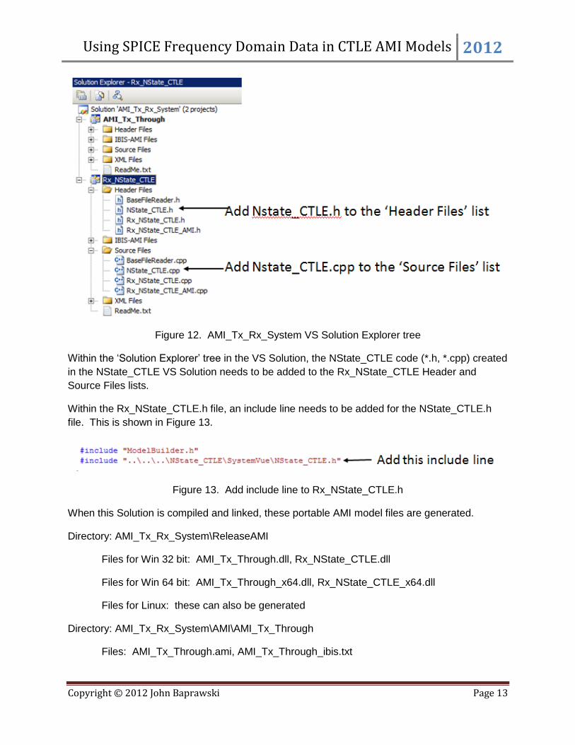
Figure 12 shows the Solution Explorer tree for the AMI_Tx_Rx_System VS Solution.
Using SPICE Frequency Domain Data in CTLE AMI Models 2012
Copyright © 2012 John Baprawski Page 13
Figure 12. AMI_Tx_Rx_System VS Solution Explorer tree
Within the ‘Solution Explorer’ tree in the VS Solution, the NState_CTLE code (*.h, *.cpp) created
in the NState_CTLE VS Solution needs to be added to the Rx_NState_CTLE Header and
Source Files lists.
Within the Rx_NState_CTLE.h file, an include line needs to be added for the NState_CTLE.h
file. This is shown in Figure 13.
Figure 13. Add include line to Rx_NState_CTLE.h
When this Solution is compiled and linked, these portable AMI model files are generated.
Directory: AMI_Tx_Rx_System\ReleaseAMI
Files for Win 32 bit: AMI_Tx_Through.dll, Rx_NState_CTLE.dll
Files for Win 64 bit: AMI_Tx_Through_x64.dll, Rx_NState_CTLE_x64.dll
Files for Linux: these can also be generated
Directory: AMI_Tx_Rx_System\AMI\AMI_Tx_Through
Files: AMI_Tx_Through.ami, AMI_Tx_Through_ibis.txt

Using SPICE Frequency Domain Data in CTLE AMI Models 2012
Copyright © 2012 John Baprawski Page 14
Directory: AMI_Tx_Rx_System\AMI\Rx_NState_CTLE
Files: Rx_NState_CTLE.ami, Rx_NState_CTLE_ibis.txt
This concludes using the custom C++ NState_CTLE SystemVue model to generate portable
AMI model files for the Rx_NState_CTLE AMI model.
Use the RX AMI model in a Channel Simulator.
Use the ADS workspace AMI_System_wrk.
To use this workspace, the generated AMI files listed in the previous step were copied to the
AMI_System_wrk\data directory. Also, in the data directory, an IBS file, AMI_System.ibs, was
setup to use the AMI_Tx_Through and Rx_NState_CTLE models.
Figure 14 shows the Folder View for the AMI_System_wrk workspace.
Figure 14. AMI_System_wrk workspace Folder View
The SParam_W_Element_test schematic was used to generate the 2 port S-parameter files for
the channels with the frequency response shown in Figure 2 above. Those 2-port S-parameter
files were used in the SystemVue AMI_Tx_Rx_System.wsv workspace.
The SParam_W_Element_4Port_test schematic was used to generate 4-port S-parameter files
for these channels for use in the SerDes system used with the ADS Channel Simulator in the
AMI_System schematic.
Figure 15 show the AMI_System schematic.

Using SPICE Frequency Domain Data in CTLE AMI Models 2012
Copyright © 2012 John Baprawski Page 15
Figure 15. AMI_System schematic.
The AMI system is setup for use of the AMI_Tx_Through AMI model as the transmitter with a 10
Gbps data stream and 1 volt p-p differential data level, use of the 16 in transmission line
channel, and use of the Rx_NState_CTLE AMI model as the receiver.
When the Channel Simulation is run, the output of the Rx_AMI model is recorded by the
Eye_Probe.
Figure 16 show the AMI system output Eye diagram.
Figure 16. AMI_System output Eye diagram

Using SPICE Frequency Domain Data in CTLE AMI Models 2012
Copyright © 2012 John Baprawski Page 16
As can be seen, the eye is restored and wide open as was observed in SystemVue in Figure 10
using the Rx_NState_CTLE model in the AMI_System_Schematic.
This concludes using the SystemVue generated AMI model Rx_NState_CTLE in a SerDes
system simulation in the ADS Channel Simulator.
Limitations and Solutions
The methodology discussed in this article was very focused but general in nature. Though it
uses very specific channels, CTLE characteristics and data rate, the methodology is general
purpose for using other SPICE generated frequency domain CTLE data in AMI models.
There are limitations in the methodology presented. Fortunately, there are solutions for many of
the limitations.
The SPICE data used was for a linear frequency sweep to a maximum frequency defined by the
data rate and samples per bit.
In actual practice, it is very reasonable to use a logarithmic frequency sweep up to a
much lower maximum frequency. This has been done in other applications.
Only 4 CTLE states were used.
In actual practice, it is very reasonable for there to be many more states. In fact, 1024
states have been used in another application.
The CTLEs were defined to provide all of the equalization for the channels.
In actual practice, the equalization is often split up between transmitter pre-emphasis,
receiver CTLE and receiver DFE. There may be multiple stages in each area as well.
Regardless, however the CTLE characteristics are defined, they can be used in this
methodology.
The CTLE responses easily provided equivalent impulse responses.
In some cases, the CTLE frequency domain data might not be well behaved in the
frequency domain. There may be sharp signal level changes in certain frequency
ranges. The frequency domain data might not be causal or meet constraints on physical
realizability. For these cases, a more sophisticated conversion process from the
frequency domain data to the equivalent impulse response is required. This may include
preconditioning the frequency data to meet the constraints of causality and physical
realizability. This has been done for such cases.
The CTLE response used provided ideal equalization for the channels used.
In actual practice, the analog circuits utilized in HSD ICs provide only a close
approximation to the ideal equalization characteristic needed. Determining a practical

Using SPICE Frequency Domain Data in CTLE AMI Models 2012
Copyright © 2012 John Baprawski Page 17
equalization characteristic usable in a HSD IC can be more of an art. Various design
techniques are available for creating such approximate equalization characteristics.
The impulse data generated was used at the same data rate used to generate the data.
Typically, the impulse data needs to be used at other data rates and samples per bit. In
most cases, the NState_CTLE model provides proper analytical processing to
automatically change the CTLE tap coefficients needed for the other data rates and
samples per bit while retaining the specified frequency domain characteristic. However,
sometimes a more sophisticated impulse analytical processing is needed. This has
been done for such cases.
The example provides only includes dlls for use on Windows.
Linux is a very popular platform for SI designers. The process easily supports Linux as
well and has been done for such cases.
The CTLE supported a fixed set of N states.
Often, it is desirable for the CTLE to automatically adapt among the N states for the
channel characteristics used. This may be in as a feedforward adaptive equalizer or as
a feedback adaptive equalizer. Adaptive CTLEs have been created using this process
as needed.
The CTLE characteristics were defined using frequency domain data.
Sometimes, it is more desirable to define the N states of a CTLE using time domain step
responses. SPICE generated time domain step response data has been used with this
methodology as needed.
The methodology defined used Microsoft Visual Studio 2008 SP1.
Sometimes, one would like to use the Microsoft Visual Studio 2010 product. The
methodology can be adapted for use with VS 2010.
The SerDes receiver design provided all of the channel equalization with the N-state CTLE.
Sometimes, it is desirable to for the SerDes receiver to include not only a CLTE, but also
a CDR, DFE, and other nonlinearities. The SerDes receiver can be as complex as
needed. Custom receiver AMI models with CTLE, DFE, CDR and other nonlinearities
have been created and available as needed.
As with any focused presentation, there is often more work involved from discussion to practical
application. Practical application is still achievable, though with some modification of the
methodology presented.
Summary
Using SPICE Frequency Domain Data in CTLE AMI Models 2012
Copyright © 2012 John Baprawski Page 18
This article presented a methodology for using data from SPICE frequency domain circuit
simulations representing N states for a CTLE circuit design in an AMI model for use in any
Channel Simulator compliant with the IBIS 5.0 AMI Standard.
The frequency domain data for the CTLE circuits generated by SPICE simulations were
converted into equivalent impulse response data.
The impulse response data was embedded into a generic NState_CTLE C++ model usable in
SystemVue.
The NState_CTLE C++ model was used in an Rx AMI design in SystemVue for modeling a
SerDes system. SystemVue was used to generate the Rx AMI model code and files. The Rx
AMI model was named Rx_NState_CTLE. Though the model was design at one specific data
rate and samples per bit characteristic, the modeling methodology enables it to be usable for
other data rates and sample per bit values.
The Rx AMI model was used in the ADS Channel Simulator and is portable for use in any other
channel simulator that is compliant with the IBIS 5.0 AMI standard.
Limitations of the approach used in this article were discussed and solutions were discussed to
overcome those limitations.
Acknowledgment
Thanks to Agilent Technologies, Inc., EEsof Division for providing the SerDes signal integrity
market with their fine line of EDA tools, SystemVue and Advanced Design System. These tools
provide a very effective and efficient process for generating portable AMI models per the IBIS
standard.
Biography
John Baprawski is Systems Engineer with over 35 years designing RF and communications
systems and EDA system design products for the RF, Communications, and High Speed Digital
markets. John was formerly with Agilent EEsof for 22 year as the R&D manager who led the
R&D team for development of system level design tools. Currently, John is a consulting
engineer for modeling high speed digital (HSD) integrated circuits (ICs) based on the industry
Input/Output Buffer Information Specification (IBIS) Algorithmic Model Interface (AMI) standard
(IBIS Version 5.0, August 29, 2008).
John Baprawski can be contacted through his Web site: http://www.johnbaprawski.com; his
Linked-In Web page www.linkedin.com/pub/john-baprawski/13/725/302; or by email at