user’s manual - tecdriver · user’s manual wf2 sensorless vector drive featuring n models with...
TRANSCRIPT

User’s ManualWF2 Sensorless Vector Drivefeaturing N models with NSF®
and BISSC certification
0.75–55.0 kW
NOW W
ITH V
ARIABLE
TORQUE RATIN
GS!

TRADEMARK NOTICE
TB Wood’s and are registered trademarks of TB Wood’s Incorporated.
DeviceNet is a registered trademark of the Open DeviceNet Vendor Association (ODVA).
Metasys is a registered trademark of Johnson Controls, Inc.
Modbus is a registered trademark of Schneider Electric.
NSF is a registered trademark of the National Sanitation Foundation.
UL is a trademark of Underwriters Laboratories, Incorporated.
®

Table of Contents
07.11.03 TB Wood’s and Berges – All Rights Reserved
08_GB WF2 — 0.75–55.0 1
1 General Information . . . . . . . . . . . . . . . . . . . . . . . . . . . . . . . . . . . . . . . . . . . . . . . . . . . . . . . . . . . . . . . . . . . . 5
1.1 Safety and Operating Instructions for Drive Converters. . . . . . . . . . . . . . . . . . . . . . . . . . . . . . . . . . . . 5
2 Introduction . . . . . . . . . . . . . . . . . . . . . . . . . . . . . . . . . . . . . . . . . . . . . . . . . . . . . . . . . . . . . . . . . . . . . . . . . . . 8
2.1 Product Overview. . . . . . . . . . . . . . . . . . . . . . . . . . . . . . . . . . . . . . . . . . . . . . . . . . . . . . . . . . . . . . . . . 8
2.2 Manual Overview . . . . . . . . . . . . . . . . . . . . . . . . . . . . . . . . . . . . . . . . . . . . . . . . . . . . . . . . . . . . . . . . . 8
2.3 Publication History . . . . . . . . . . . . . . . . . . . . . . . . . . . . . . . . . . . . . . . . . . . . . . . . . . . . . . . . . . . . . . . . 9
3 Technical Characteristics . . . . . . . . . . . . . . . . . . . . . . . . . . . . . . . . . . . . . . . . . . . . . . . . . . . . . . . . . . . . . . 10
3.1 Interpreting Model Numbers. . . . . . . . . . . . . . . . . . . . . . . . . . . . . . . . . . . . . . . . . . . . . . . . . . . . . . . . 10
3.2 Power and Current Ratings . . . . . . . . . . . . . . . . . . . . . . . . . . . . . . . . . . . . . . . . . . . . . . . . . . . . . . . . 10
3.3 Environmental . . . . . . . . . . . . . . . . . . . . . . . . . . . . . . . . . . . . . . . . . . . . . . . . . . . . . . . . . . . . . . . . . . 12
3.4 Electrical. . . . . . . . . . . . . . . . . . . . . . . . . . . . . . . . . . . . . . . . . . . . . . . . . . . . . . . . . . . . . . . . . . . . . . . 12
3.5 Control Features . . . . . . . . . . . . . . . . . . . . . . . . . . . . . . . . . . . . . . . . . . . . . . . . . . . . . . . . . . . . . . . . 13
3.6 Dimensions . . . . . . . . . . . . . . . . . . . . . . . . . . . . . . . . . . . . . . . . . . . . . . . . . . . . . . . . . . . . . . . . . . . . 14
3.7 Weights of Models . . . . . . . . . . . . . . . . . . . . . . . . . . . . . . . . . . . . . . . . . . . . . . . . . . . . . . . . . . . . . . . 17
4 Installation . . . . . . . . . . . . . . . . . . . . . . . . . . . . . . . . . . . . . . . . . . . . . . . . . . . . . . . . . . . . . . . . . . . . . . . . . . . 18
4.1 Preliminary Inspection . . . . . . . . . . . . . . . . . . . . . . . . . . . . . . . . . . . . . . . . . . . . . . . . . . . . . . . . . . . . 18
4.2 Installation Precautions . . . . . . . . . . . . . . . . . . . . . . . . . . . . . . . . . . . . . . . . . . . . . . . . . . . . . . . . . . . 18
4.3 Considerations for Mounting IP31 and IP55 Models in Host Enclosures. . . . . . . . . . . . . . . . . . . . . . 18
4.3.1 IP31 and IP55 Models Entirely Enclosed in the Host Enclosure . . . . . . . . . . . . . . . . . . . . 19
4.3.2 IP31 and IP55 Models with Fins External to the Host Enclosure . . . . . . . . . . . . . . . . . . . . 19
4.4 Maintenance/Environmental Integrity. . . . . . . . . . . . . . . . . . . . . . . . . . . . . . . . . . . . . . . . . . . . . . . . . 21
4.4.1 Removal of the Conduit Plate on NEMA 1/IP31 Models. . . . . . . . . . . . . . . . . . . . . . . . . . . 21
4.4.2 Minimum Torque Values to Secure Cover . . . . . . . . . . . . . . . . . . . . . . . . . . . . . . . . . . . . . 22
4.5 EMC (Electromagnetic Compatibility) . . . . . . . . . . . . . . . . . . . . . . . . . . . . . . . . . . . . . . . . . . . . . . . . 22
4.5.1 Limit Classes . . . . . . . . . . . . . . . . . . . . . . . . . . . . . . . . . . . . . . . . . . . . . . . . . . . . . . . . . . . 22
4.5.2 Interference Suppression Measures. . . . . . . . . . . . . . . . . . . . . . . . . . . . . . . . . . . . . . . . . . 23
4.5.3 EMC Ordinance (EMC Directive, 89/336 EEC) . . . . . . . . . . . . . . . . . . . . . . . . . . . . . . . . . 25
5 Connections . . . . . . . . . . . . . . . . . . . . . . . . . . . . . . . . . . . . . . . . . . . . . . . . . . . . . . . . . . . . . . . . . . . . . . . . . 26
5.1 Introduction . . . . . . . . . . . . . . . . . . . . . . . . . . . . . . . . . . . . . . . . . . . . . . . . . . . . . . . . . . . . . . . . . . . . 26
5.2 General Wiring Information . . . . . . . . . . . . . . . . . . . . . . . . . . . . . . . . . . . . . . . . . . . . . . . . . . . . . . . . 26
5.2.1 Wiring Practices . . . . . . . . . . . . . . . . . . . . . . . . . . . . . . . . . . . . . . . . . . . . . . . . . . . . . . . . . 26
5.2.2 Considerations for Power Wiring and Motor Lead Length . . . . . . . . . . . . . . . . . . . . . . . . . 26
5.2.3 Line Power Connection. . . . . . . . . . . . . . . . . . . . . . . . . . . . . . . . . . . . . . . . . . . . . . . . . . . . 27
5.2.4 Use of Fault Current Safety Switches. . . . . . . . . . . . . . . . . . . . . . . . . . . . . . . . . . . . . . . . . 27
5.2.5 Considerations for Control Wiring. . . . . . . . . . . . . . . . . . . . . . . . . . . . . . . . . . . . . . . . . . . . 28
5.3 Input Line Requirements . . . . . . . . . . . . . . . . . . . . . . . . . . . . . . . . . . . . . . . . . . . . . . . . . . . . . . . . . . 30
5.3.1 Line Voltage . . . . . . . . . . . . . . . . . . . . . . . . . . . . . . . . . . . . . . . . . . . . . . . . . . . . . . . . . . . . 30
5.3.2 Line Capacity . . . . . . . . . . . . . . . . . . . . . . . . . . . . . . . . . . . . . . . . . . . . . . . . . . . . . . . . . . . 30
5.3.3 Use of Isolation Transformers and Line Reactors . . . . . . . . . . . . . . . . . . . . . . . . . . . . . . . 31
5.3.4 Phase Imbalance . . . . . . . . . . . . . . . . . . . . . . . . . . . . . . . . . . . . . . . . . . . . . . . . . . . . . . . . 31
5.3.5 Power System Configuration . . . . . . . . . . . . . . . . . . . . . . . . . . . . . . . . . . . . . . . . . . . . . . . 31
5.4 Terminals Found on the WF2 Power Board. . . . . . . . . . . . . . . . . . . . . . . . . . . . . . . . . . . . . . . . . . . . 31
5.4.1 Description of the Terminals . . . . . . . . . . . . . . . . . . . . . . . . . . . . . . . . . . . . . . . . . . . . . . . . 31
5.4.2 Typical Power Connections . . . . . . . . . . . . . . . . . . . . . . . . . . . . . . . . . . . . . . . . . . . . . . . . 32

Table of Contents
TB Wood’s and Berges – All Rights Reserved 07.11.03
WF2 — 0.75–55.0 08_GB2
5.5 Dynamic Braking . . . . . . . . . . . . . . . . . . . . . . . . . . . . . . . . . . . . . . . . . . . . . . . . . . . . . . . . . . . . . . . . 34
5.5.1 Dynamic Braking Units . . . . . . . . . . . . . . . . . . . . . . . . . . . . . . . . . . . . . . . . . . . . . . . . . . . . 35
5.5.2 User-Supplied External Resistor. . . . . . . . . . . . . . . . . . . . . . . . . . . . . . . . . . . . . . . . . . . . . 35
5.6 Terminals Found on the WF2 Control Board . . . . . . . . . . . . . . . . . . . . . . . . . . . . . . . . . . . . . . . . . . . 36
5.6.1 Description of the Control Terminals. . . . . . . . . . . . . . . . . . . . . . . . . . . . . . . . . . . . . . . . . . 36
5.6.2 Configuring the Type and Range of Analog Inputs . . . . . . . . . . . . . . . . . . . . . . . . . . . . . . . 38
5.6.3 Control Wiring Connections (Active-High Logic) . . . . . . . . . . . . . . . . . . . . . . . . . . . . . . . . . 40
5.6.4 Control Wiring Connections (Active-Low Logic) . . . . . . . . . . . . . . . . . . . . . . . . . . . . . . . . . 48
5.7 Modbus Connection . . . . . . . . . . . . . . . . . . . . . . . . . . . . . . . . . . . . . . . . . . . . . . . . . . . . . . . . . . . . . . 52
6 Set-up and Getting Started. . . . . . . . . . . . . . . . . . . . . . . . . . . . . . . . . . . . . . . . . . . . . . . . . . . . . . . . . . . . . . 53
6.1 Introduction. . . . . . . . . . . . . . . . . . . . . . . . . . . . . . . . . . . . . . . . . . . . . . . . . . . . . . . . . . . . . . . . . . . . . 53
6.2 Description of the Standard Keypad. . . . . . . . . . . . . . . . . . . . . . . . . . . . . . . . . . . . . . . . . . . . . . . . . . 53
6.2.1 Overview . . . . . . . . . . . . . . . . . . . . . . . . . . . . . . . . . . . . . . . . . . . . . . . . . . . . . . . . . . . . . . . 53
6.2.2 Description of the Keys on the Standard Keypad . . . . . . . . . . . . . . . . . . . . . . . . . . . . . . . . 54
6.2.3 Modes and Displays of the Standard Keypad. . . . . . . . . . . . . . . . . . . . . . . . . . . . . . . . . . . 55
6.2.4 Description of the LEDs on the Standard Keypad . . . . . . . . . . . . . . . . . . . . . . . . . . . . . . . 58
6.2.5 Upgrading Firmware by Reflashing. . . . . . . . . . . . . . . . . . . . . . . . . . . . . . . . . . . . . . . . . . . 59
6.3 Quick Start . . . . . . . . . . . . . . . . . . . . . . . . . . . . . . . . . . . . . . . . . . . . . . . . . . . . . . . . . . . . . . . . . . . . . 59
6.4 Description of the Enhanced Keypad . . . . . . . . . . . . . . . . . . . . . . . . . . . . . . . . . . . . . . . . . . . . . . . . . 60
6.4.1 Introduction . . . . . . . . . . . . . . . . . . . . . . . . . . . . . . . . . . . . . . . . . . . . . . . . . . . . . . . . . . . . . 60
6.4.2 Keys on the Enhanced Keypad. . . . . . . . . . . . . . . . . . . . . . . . . . . . . . . . . . . . . . . . . . . . . . 60
6.4.3 Modes and Displays of the Enhanced Keypad . . . . . . . . . . . . . . . . . . . . . . . . . . . . . . . . . . 62
6.4.4 LEDs on the Enhanced Keypad . . . . . . . . . . . . . . . . . . . . . . . . . . . . . . . . . . . . . . . . . . . . . 68
6.5 Security . . . . . . . . . . . . . . . . . . . . . . . . . . . . . . . . . . . . . . . . . . . . . . . . . . . . . . . . . . . . . . . . . . . . . . . 68
6.5.1 Access Levels . . . . . . . . . . . . . . . . . . . . . . . . . . . . . . . . . . . . . . . . . . . . . . . . . . . . . . . . . . . 68
6.5.2 Gaining Access when Security Enabled . . . . . . . . . . . . . . . . . . . . . . . . . . . . . . . . . . . . . . . 68
6.5.3 Disabling Security . . . . . . . . . . . . . . . . . . . . . . . . . . . . . . . . . . . . . . . . . . . . . . . . . . . . . . . . 69
6.6 Control Paths . . . . . . . . . . . . . . . . . . . . . . . . . . . . . . . . . . . . . . . . . . . . . . . . . . . . . . . . . . . . . . . . . . . 69
6.6.1 Overview of Control Paths . . . . . . . . . . . . . . . . . . . . . . . . . . . . . . . . . . . . . . . . . . . . . . . . . 69
6.6.2 Selection of Control Paths . . . . . . . . . . . . . . . . . . . . . . . . . . . . . . . . . . . . . . . . . . . . . . . . . 70
6.7 Serial Link Communication. . . . . . . . . . . . . . . . . . . . . . . . . . . . . . . . . . . . . . . . . . . . . . . . . . . . . . . . . 72
6.7.1 Configuration of the Serial Link. . . . . . . . . . . . . . . . . . . . . . . . . . . . . . . . . . . . . . . . . . . . . . 73
6.7.2 Parameter Addresses . . . . . . . . . . . . . . . . . . . . . . . . . . . . . . . . . . . . . . . . . . . . . . . . . . . . . 73
6.7.3 Drive Control via the Serial Link . . . . . . . . . . . . . . . . . . . . . . . . . . . . . . . . . . . . . . . . . . . . . 73
6.7.4 Override of Serial Link Control . . . . . . . . . . . . . . . . . . . . . . . . . . . . . . . . . . . . . . . . . . . . . . 73
7 Parameters. . . . . . . . . . . . . . . . . . . . . . . . . . . . . . . . . . . . . . . . . . . . . . . . . . . . . . . . . . . . . . . . . . . . . . . . . . . 74
7.1 Introduction. . . . . . . . . . . . . . . . . . . . . . . . . . . . . . . . . . . . . . . . . . . . . . . . . . . . . . . . . . . . . . . . . . . . . 74
7.2 Parameter Groups . . . . . . . . . . . . . . . . . . . . . . . . . . . . . . . . . . . . . . . . . . . . . . . . . . . . . . . . . . . . . . . 74
7.3 Security Group . . . . . . . . . . . . . . . . . . . . . . . . . . . . . . . . . . . . . . . . . . . . . . . . . . . . . . . . . . . . . . . . . . 75
7.4 Drive ID Group . . . . . . . . . . . . . . . . . . . . . . . . . . . . . . . . . . . . . . . . . . . . . . . . . . . . . . . . . . . . . . . . . . 76
7.5 Drive Status Group. . . . . . . . . . . . . . . . . . . . . . . . . . . . . . . . . . . . . . . . . . . . . . . . . . . . . . . . . . . . . . . 78
7.6 Input Status Group . . . . . . . . . . . . . . . . . . . . . . . . . . . . . . . . . . . . . . . . . . . . . . . . . . . . . . . . . . . . . . . 81
7.7 Control Modes Group . . . . . . . . . . . . . . . . . . . . . . . . . . . . . . . . . . . . . . . . . . . . . . . . . . . . . . . . . . . . . 83
7.8 Speed Reference Group . . . . . . . . . . . . . . . . . . . . . . . . . . . . . . . . . . . . . . . . . . . . . . . . . . . . . . . . . . 88

Table of Contents
07.11.03 TB Wood’s and Berges – All Rights Reserved
08_GB WF2 — 0.75–55.0 3
7.9 Ramps Group. . . . . . . . . . . . . . . . . . . . . . . . . . . . . . . . . . . . . . . . . . . . . . . . . . . . . . . . . . . . . . . . . . . 92
7.10 Preset Speeds Group. . . . . . . . . . . . . . . . . . . . . . . . . . . . . . . . . . . . . . . . . . . . . . . . . . . . . . . . . . . . . 96
7.11 Skip Freq Group. . . . . . . . . . . . . . . . . . . . . . . . . . . . . . . . . . . . . . . . . . . . . . . . . . . . . . . . . . . . . . . . . 97
7.12 Torque Limits Group . . . . . . . . . . . . . . . . . . . . . . . . . . . . . . . . . . . . . . . . . . . . . . . . . . . . . . . . . . . . . 98
7.13 Drive Output Group . . . . . . . . . . . . . . . . . . . . . . . . . . . . . . . . . . . . . . . . . . . . . . . . . . . . . . . . . . . . . 100
7.14 Motor Setup Group. . . . . . . . . . . . . . . . . . . . . . . . . . . . . . . . . . . . . . . . . . . . . . . . . . . . . . . . . . . . . . 103
7.15 Braking Options Group. . . . . . . . . . . . . . . . . . . . . . . . . . . . . . . . . . . . . . . . . . . . . . . . . . . . . . . . . . . 106
7.16 Digital Inputs Group . . . . . . . . . . . . . . . . . . . . . . . . . . . . . . . . . . . . . . . . . . . . . . . . . . . . . . . . . . . . . 110
7.17 Analog Inputs Group . . . . . . . . . . . . . . . . . . . . . . . . . . . . . . . . . . . . . . . . . . . . . . . . . . . . . . . . . . . . 113
7.18 Digital Outputs Group. . . . . . . . . . . . . . . . . . . . . . . . . . . . . . . . . . . . . . . . . . . . . . . . . . . . . . . . . . . . 117
7.19 Analog Outputs Group . . . . . . . . . . . . . . . . . . . . . . . . . . . . . . . . . . . . . . . . . . . . . . . . . . . . . . . . . . . 120
7.20 Fault Management Group . . . . . . . . . . . . . . . . . . . . . . . . . . . . . . . . . . . . . . . . . . . . . . . . . . . . . . . . 122
7.21 Display Options Group . . . . . . . . . . . . . . . . . . . . . . . . . . . . . . . . . . . . . . . . . . . . . . . . . . . . . . . . . . . 127
7.22 Special Group . . . . . . . . . . . . . . . . . . . . . . . . . . . . . . . . . . . . . . . . . . . . . . . . . . . . . . . . . . . . . . . . . 130
7.23 Communication Group . . . . . . . . . . . . . . . . . . . . . . . . . . . . . . . . . . . . . . . . . . . . . . . . . . . . . . . . . . . 131
7.24 PID Configure Group . . . . . . . . . . . . . . . . . . . . . . . . . . . . . . . . . . . . . . . . . . . . . . . . . . . . . . . . . . . . 135
7.25 Ungrouped Parameters . . . . . . . . . . . . . . . . . . . . . . . . . . . . . . . . . . . . . . . . . . . . . . . . . . . . . . . . . . 139
8 Troubleshooting . . . . . . . . . . . . . . . . . . . . . . . . . . . . . . . . . . . . . . . . . . . . . . . . . . . . . . . . . . . . . . . . . . . . . 141
8.1 WF2 Fault Codes . . . . . . . . . . . . . . . . . . . . . . . . . . . . . . . . . . . . . . . . . . . . . . . . . . . . . . . . . . . . . . . 141
9 WF2 Options . . . . . . . . . . . . . . . . . . . . . . . . . . . . . . . . . . . . . . . . . . . . . . . . . . . . . . . . . . . . . . . . . . . . . . . . 145
9.1 Remote Keypad Kits . . . . . . . . . . . . . . . . . . . . . . . . . . . . . . . . . . . . . . . . . . . . . . . . . . . . . . . . . . . . 145
9.2 IP31–IP21 Conversion Kits . . . . . . . . . . . . . . . . . . . . . . . . . . . . . . . . . . . . . . . . . . . . . . . . . . . . . . . 145
9.3 SIOC02 Serial Port Converter . . . . . . . . . . . . . . . . . . . . . . . . . . . . . . . . . . . . . . . . . . . . . . . . . . . . . 145
9.4 Reflash Tool . . . . . . . . . . . . . . . . . . . . . . . . . . . . . . . . . . . . . . . . . . . . . . . . . . . . . . . . . . . . . . . . . . . 145
9.5 Dynamic Braking Units. . . . . . . . . . . . . . . . . . . . . . . . . . . . . . . . . . . . . . . . . . . . . . . . . . . . . . . . . . . 145
9.6 DeviceNet Option Board . . . . . . . . . . . . . . . . . . . . . . . . . . . . . . . . . . . . . . . . . . . . . . . . . . . . . . . . . 145
9.7 Analog Input/Output Option Board . . . . . . . . . . . . . . . . . . . . . . . . . . . . . . . . . . . . . . . . . . . . . . . . . . 145
10 Sequencer Application . . . . . . . . . . . . . . . . . . . . . . . . . . . . . . . . . . . . . . . . . . . . . . . . . . . . . . . . . . . . . . . . 146
10.1 Introduction . . . . . . . . . . . . . . . . . . . . . . . . . . . . . . . . . . . . . . . . . . . . . . . . . . . . . . . . . . . . . . . . . . . 146
10.2 Parameters Modified by the Application. . . . . . . . . . . . . . . . . . . . . . . . . . . . . . . . . . . . . . . . . . . . . . 146
10.2.1 Parameters No Longer Available . . . . . . . . . . . . . . . . . . . . . . . . . . . . . . . . . . . . . . . . . . . 146
10.2.2 Parameters With Changed Functionality . . . . . . . . . . . . . . . . . . . . . . . . . . . . . . . . . . . . . 147
10.3 Parameters Added by the Application . . . . . . . . . . . . . . . . . . . . . . . . . . . . . . . . . . . . . . . . . . . . . . . 147
10.3.1 Parameters Added to the Drive Status Group . . . . . . . . . . . . . . . . . . . . . . . . . . . . . . . . . 147
10.3.2 Parameters Added to the Ramps Group . . . . . . . . . . . . . . . . . . . . . . . . . . . . . . . . . . . . . 148
10.3.3 Seq Configure Group . . . . . . . . . . . . . . . . . . . . . . . . . . . . . . . . . . . . . . . . . . . . . . . . . . . . 148
11 Summary of WF2 Parameters . . . . . . . . . . . . . . . . . . . . . . . . . . . . . . . . . . . . . . . . . . . . . . . . . . . . . . . . . . 156
11.1 Parameter Groups . . . . . . . . . . . . . . . . . . . . . . . . . . . . . . . . . . . . . . . . . . . . . . . . . . . . . . . . . . . . . . 156
11.2 Parameters Available in Level 1 Programming (Standard Keypad Only) . . . . . . . . . . . . . . . . . . . . 156
12 Hexadecimal to Binary Conversion. . . . . . . . . . . . . . . . . . . . . . . . . . . . . . . . . . . . . . . . . . . . . . . . . . . . . . 179
13 Fundamentals of PID Control . . . . . . . . . . . . . . . . . . . . . . . . . . . . . . . . . . . . . . . . . . . . . . . . . . . . . . . . . . 180
13.1 Introduction . . . . . . . . . . . . . . . . . . . . . . . . . . . . . . . . . . . . . . . . . . . . . . . . . . . . . . . . . . . . . . . . . . . 180
13.2 Configuration of PID Control Parameters. . . . . . . . . . . . . . . . . . . . . . . . . . . . . . . . . . . . . . . . . . . . . 180

Table of Contents
TB Wood’s and Berges – All Rights Reserved 07.11.03
WF2 — 0.75–55.0 08_GB4
13.2.1 Parameter PID Configure . . . . . . . . . . . . . . . . . . . . . . . . . . . . . . . . . . . . . . . . . . . . . . . . . 180
13.2.2 Parameter PID Direct Type. . . . . . . . . . . . . . . . . . . . . . . . . . . . . . . . . . . . . . . . . . . . . . . . 182
13.2.3 Parameter Feedback Config . . . . . . . . . . . . . . . . . . . . . . . . . . . . . . . . . . . . . . . . . . . . . . . 182
13.2.4 Parameter Feedback Gain . . . . . . . . . . . . . . . . . . . . . . . . . . . . . . . . . . . . . . . . . . . . . . . . 182
13.2.5 Parameter PID Prop Gain . . . . . . . . . . . . . . . . . . . . . . . . . . . . . . . . . . . . . . . . . . . . . . . . . 182
13.2.6 Parameter PID Int Gain. . . . . . . . . . . . . . . . . . . . . . . . . . . . . . . . . . . . . . . . . . . . . . . . . . . 183
13.2.7 Parameter PID Deriv Gain . . . . . . . . . . . . . . . . . . . . . . . . . . . . . . . . . . . . . . . . . . . . . . . . 183
13.3 Tuning the PID Control Loop . . . . . . . . . . . . . . . . . . . . . . . . . . . . . . . . . . . . . . . . . . . . . . . . . . . . . . 183

07.11.03 TB Wood’s and Berges – All Rights Reserved
08_GB WF2 — 0.75–55.0 5
General Information
1 General Information
1.1 Safety and Operating Instructions for Drive Converters
1. General
In operation, drive converters, depending on their degree of protection, may have live,unisolated, and possibly also moving or rotating parts, as well as hot surfaces.
In case of inadmissible removal of the required covers, of improper use, wrong installationor maloperation, there is the danger of serious personal injury and damage to property.
For further information, see documentation.
All operations serving transport, installation and commissioning as well as maintenance areto be carried out by skilled technical personnel (Observe IEC 364 or CENELEC HD 384or DIN VDE 0100 and IEC 664 or DIN/VDE 0110 and national accident prevention rules!).
For the purposes of these basic safety instructions, “skilled technical personnel” means per-sons who are familiar with the installation, mounting, commissioning and operation of theproduct and have the qualifications needed for the performance of their functions.
We draw attention to the fact that no liability can be assumed for damage and malfunctionsresulting from failure to observe the operating manual.
We draw attention to the fact that no liability can be assumed for damage and malfunctionsresulting from failure to observe the operating manual.
2. Intended Use
The application of the drive converter described in this operating manual exclusively servesthe purpose of continuously variable speed control of three-phase motors.
Drive converters are components designed for inclusion in electrical installations or machin-ery.
The drive converters are designed for installation in a switchgear cabinet and for permanentconnection.
The operator of the system is solely liable for damage resulting from improper use of thedrive converter.
Only items expressly approved by BERGES (e.g. line filter, choke, external braking chop-pers and braking resistors etc.) may be used as accessories.
The installer of the system is liable for any damage resulting from the use of accessoriesthat have not been approved expressly by BERGES. Please consult us in case of doubt.
In case of installation in machinery, commissioning of the drive converters (i.e. the startingof normal operation) is prohibited until the machinery has been proved to conform to theprovisions of the directive 89/392/EEC (Machinery Safety Directive – MSD). Account is tobe taken of EN 60204.
Commissioning (i.e. the starting of normal operation) is admissible only where conformitywith the EMC directive (89/336/EEC) has been established.
The drive converters meet the requirements of the low-voltage directive 73/23/EEC. Theyare subject to the harmonized standards of the series prEN 50178/DIN VDE 0160 in con-junction with EN 60439-1/DIN VDE 0660, part 500, and EN 60146/DIN VDE 0558.
The technical data as well as information concerning the supply conditions shall be takenfrom the name plate and from the documentation and shall be strictly observed.

General Information
TB Wood’s and Berges – All Rights Reserved 07.11.03
WF2 — 0.75–55.0 08_GB6
3. Transport, Storage
The instructions for transport, storage and proper use shall be complied with.
Damage established after delivery must be notified to the transport company immediately.Where necessary, the supplier must also be notified before the damaged drive converter isput into operation.
The climatic conditions shall be in conformity with prEN 50178.
4. Installation
The installation and cooling of the appliances shall be in accordance with the specificationsin the pertinent documentation.
The drive converters shall be protected against excessive strains. In particular, no compo-nents must be bent or isolating distances altered in the course of transportation or handling.No contact shall be made with electronic components and contacts.
Drive converters contain electrostatic sensitive components which are liable to damagethrough improper use. Electric components must not be mechanically damaged or de-stroyed (potential health risks).
5. Electrical connection
When working on live drive converters, the applicable national accident prevention rules(e.g. VBG 4) must be complied with.
The electrical installation shall be carried out in accordance with the relevant requirements(e.g. cross-sectional areas of conductors, fusing, GND connection). For further information,see documentation.
Instructions for the installation in accordance with EMC requirements, like screening, earth-ing, location of filters and wiring, are contained in the drive converter documentation. Theymust always be complied with, also for drive converters bearing a CE marking. Observanceof the limit values required by EMC law is the responsibility of the manufacturer of the in-stallation or machine.
6. Operation
The components of the power section and certain elements of the control section are con-nected to the line voltage when the drive converter is connected to the line voltage. Touch-ing these components involves mortal danger!
Always isolate the drive converter from the line supply before performing any work on theelectrical or mechanical part of the system.
Disconnect the drive converter from the line voltage before removing the terminal cover orthe housing (e.g. by removing or deactivating on-site fuses or by deactivating a masterswitch isolating all poles etc.).
After disconnection of the drive converters from the voltage supply, live appliance parts andpower terminals must not be touched immediately because of possibly energized capaci-tors. In this respect, the corresponding signs and markings on the drive converter must berespected. After switching off the line voltage, wait for at least 5 minutes before beginningwork on or in the drive converter. Disconnect all power before servicing the drive. Thenmeasure the DC bus capacitor charge between the B+ and B– terminals (or DB1 and B–terminals, depending on model; see page 31 for more information) to verify that the DC volt-age is less than 45 V DC. The DC Bus LED is not a definitive indication of the absenceof DC voltage. In the event of malfunctions, the Discharge time of 5 minutes may be ex-ceeded substantially.

07.11.03 TB Wood’s and Berges – All Rights Reserved
08_GB WF2 — 0.75–55.0 7
General Information
The drive converter contains protective facilities that deactivate it in the event of malfunc-tions, whereby the motor is de-energized and comes to a standstill (so-called “coasting” ofthe motor is possible depending on the rotating mass of the type of drive involved). Stand-still of the motor can, however, also be produced by mechanical blockage. Voltage fluctua-tions, and particularly line power failures, may also lead to deactivation. In certain circum-stances, the drive may start up automatically once the cause of the fault has been reme-died. As a result of this, certain systems may be damaged or destroyed and there may bea risk for operators working on the system. Installations which include drive converters shallbe equipped with additional control and protective devices in accordance with the relevantapplicable safety requirements, e.g. Act respecting technical equipment, accident preven-tion rules etc. Changes to the drive converters by means of the operating software are Ad-missible.
The motor may be stopped during operation by disabling it or by deactivating the setpoint,whereby the drive converter and motor may remain live. If inadvertent start-up of the mo-tor must be excluded to protect operating personnel, electronic interlocking by dis-abling the motor or by deactivating the setpoint is inadequate. This is why the driveconverter must be isolated from the line voltage.
During operation, all covers and doors shall be kept closed.
Measuring instruments must be connected and disconnected only in de-energized condi-tion.
Unauthorized conversions or modifications on or in the drive converter and its componentsand accessories will render all warranty claims void.
When installing an option board, observe the installation specification valid for this board.
Please contact BERGES if conversions or modifications are necessary, particularly if elec-trical components are involved.
7. Maintenance and Servicing
The manufacturer’s documentation shall be followed.
KEEP SAFETY INSTRUCTIONS IN A SAFE PLACE!

Introduction
TB Wood’s and Berges – All Rights Reserved 07.11.03
WF2 — 0.75–55.0 08_GB8
2 Introduction
2.1 Product Overview
The WF2 drive is powerful and versatile. Its standard NEMA 1/IP31 enclosure removes theneed for mounting in a separate enclosure. It is also available in a NEMA 12/IP55 versionfor dusty environments and an IP66 version that complies with NSF® and BISSC certifica-tion (these are designated “N models”).
An “X” in the following table indicates the models that are currently available (see section3.1 on page 10 for information about the model number for a particular model); all modelsexcept 18.5 to 55.0 kW models are available in NSF/BISSC-certified configurations.
With over 200 parameters, the WF2 drive is capable of handling a wide variety of applica-tions. All parameters are available via the keypad on the drive; however, security may beenabled to prevent unauthorized access to the parameters.
2.2 Manual Overview
This manual contains specifications, receiving and installation instructions, configuration,description of operation, and troubleshooting procedures for WF2 drives.
KW rating
Input Voltage
115 V ACSingle-Phase
230 V ACSingle-Phase
230 V ACThree-Phase
460 V ACThree-Phase
575 V ACThree-Phase
0.75 X X X X X
1.5 X X X X
2.2 X X X X
3.7 X X X
5.5 X X X
7.5 X X X
11.0 X X X
15.0 X X X
18.5 X X X
22.0 X X X
30.0 X X
37.0 X X
45.0 X X
55.0 X X
07.11.03 TB Wood’s and Berges – All Rights Reserved
08_GB WF2 — 0.75–55.0 9
Introduction
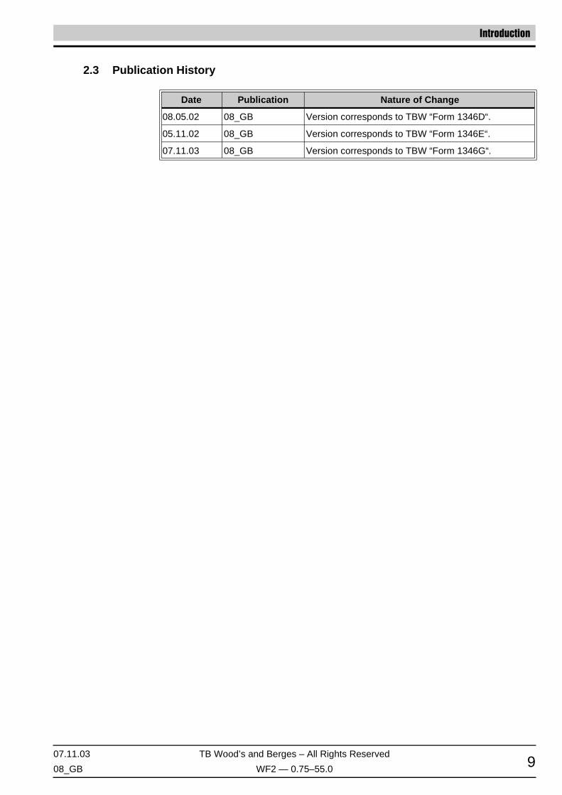
2.3 Publication History
Date Publication Nature of Change
08.05.02 08_GB Version corresponds to TBW “Form 1346D“.
05.11.02 08_GB Version corresponds to TBW “Form 1346E“.
07.11.03 08_GB Version corresponds to TBW “Form 1346G“.

Technical Characteristics
TB Wood’s and Berges – All Rights Reserved 07.11.03
WF2 — 0.75–55.0 08_GB10
3 Technical Characteristics
3.1 Interpreting Model Numbers
The model number of the WF2 drive appears on the shipping carton label and on the tech-nical data label affixed to the model. The information provided by the model number isshown below:
3.2 Power and Current Ratings
ModelNumberWF2K-
Motor Power
InputVoltage
Maximum Input Current (A)
OutputVoltage
Output Current (A)
ConstantTorque
VariableTorque
ConstantTorque
VariableTorque
ConstantTorque
VariableTorque
kW HP kW HP200 V
AC230 V
AC200 V
AC230 V
AC200 V
AC230 V
AC200 V
AC230 V
AC
1S00-7x 0.75 1.0 0.75 1.01-phase
115 V AC, ±10%– 15.0 [1]
[1] Input current is from the rated 115 V AC source.
– 15.0 [1]
0–230 V AC
– 4.2 – 4.2
2S00-7x 0.75 1.0 0.75 1.01-phase
200–230 V AC±15%
8.9 8.0 8.9 8.0 4.8 4.2 4.8 4.2
2S01-5x 1.5 2.0 1.5 2.0 16.2 14.6 16.2 14.6 7.8 6.8 7.8 6.8
2S02-2x 2.2 3.0 2.2 3.0 23.0 20.7 23.0 20.7 11.0 9.6 11.0 9.6
2000-7x 0.75 1.0 1.1 1.5
3-phase200–230 V AC
±15%
5.6 4.8 6.7 6.7 4.8 4.2 5.7 5.7
2001-5x 1.5 2.0 1.5 2.0 9.0 7.8 9.0 7.8 7.8 6.8 7.8 6.8
2002-2x 2.2 3.0 4.0 5.0 12.7 11.0 15.4 15.4 11.0 9.6 13.1 13.1
2003-7x 4.0 5.0 5.5 7.5 20.2 17.5 25.3 25.3 17.5 15.2 22.0 22.0
2005-5x 5.5 7.5 7.5 10.0 29.2 25.3 32.2 32.2 25.3 22.0 28.0 28.0
2007-5x 7.5 10.0 7.5 10.0 37.2 32.2 37.2 32.2 32.2 28.0 32.2 28.0
2011-0x 11.0 15.0 15.0 20.0 52.1 46.4 63.3 63.3 48.3 42.0 54.0 54.0
2015-0x 15.0 20.0 18.5 25.0 62.1 54.0 68.0 68.0 62.1 54.0 68.0 68.0
2018-5x 18.5 25.0 22.0 30.0 78.2 68.0 80.0 80.0 78.2 68.0 80.0 80.0
2022-0x 22.0 30.0 30.0 40.0 92.0 80.0 104.0 104.0 92.0 80.0 104.0 104.0
Table 1115 and 230 V AC Models

07.11.03 TB Wood’s and Berges – All Rights Reserved
08_GB WF2 — 0.75–55.0 11
Technical Characteristics
ModelNumberWF2K-
Motor Power
InputVoltage
Maximum Input Current (A)
OutputVoltage
Output Current (A)
ConstantTorque
VariableTorque
ConstantTorque
VariableTorque
ConstantTorque
VariableTorque
kW HP kW HP380 V
AC460 V
AC380 V
AC460 V
AC380 V
AC460 V
AC380 V
AC460 V
AC
4000-7x 0.75 1.0 1.1 1.5
3-phase380–460 V AC
±15%
3.0 2.4 3.2 3.2
0–460 V AC
2.4 2.1 2.8 2.8
4001-5x 1.5 2.0 1.5 2.0 5.2 3.9 5.2 3.9 3.8 3.4 3.8 3.4
4002-2x 2.2 3.0 3.0 5.0 7.2 5.6 7.7 7.7 5.7 4.8 6.6 6.6
4003-7x 4.0 5.0 5.0 7.5 12.0 8.8 12.8 12.8 8.9 7.6 11.0 11.0
4005-5x 5.5 7.5 6.7 10.0 15.0 12.8 16.3 16.3 12.0 11.0 14.0 14.0
4007-5x 7.5 10.0 7.5 10.0 19.7 16.3 19.7 16.3 15.6 14.0 15.6 14.0
4011-0x 11.0 15.0 13.0 20.0 30.9 25.8 33.3 33.3 23.0 21.0 27.0 27.0
4015-0x 15.0 20.0 15.0 20.0 40.0 33.3 40.0 33.3 31.0 27.0 31.0 27.0
4018-5x 18.5 25.0 20.5 30.0 46.3 40.0 47.8 47.8 37.0 34.0 40.0 40.0
4022-0x 22.0 30.0 25.5 40.0 57.5 47.8 62.4 62.4 43.0 40.0 52.0 52.0
4030-0x 30.0 40.0 33.9 50.0 62.8 53.3 65.0 65.0 61.0 52.0 65.0 65.0
4037-0x 37.0 50.0 40.3 60.0 71.0 65.0 77.0 77.0 71.0 65.0 77.0 77.0
4045-0x 45.0 60.0 50.3 75.0 86.0 77.0 96.0 96.0 86.0 77.0 96.0 96.0
4055-0x 55.0 75.0 55.0 82.0 105.0 96.0 105.0 105.0 105.0 96.0 105.0 105.0
Table 2460 V AC Models
ModelNumberWF2K-
Motor Power
InputVoltage
Maximum Input Current (A)
OutputVoltage
Output Current (A)
ConstantTorque
VariableTorque
ConstantTorque
VariableTorque
ConstantTorque
VariableTorque
kW HP kW HP 575 V AC 575 V AC 575 V AC 575 V AC
5000-7x 0.75 1.0 1.1 1.5
3-phase575 V AC
±15%
2.0 3.1
0–575 V AC
1.7 2.3
5001-5x 1.5 2.0 1.5 2.0 3.6 3.6 2.7 2.7
5002-2x 2.2 3.0 4.0 5.0 5.0 6.8 3.9 5.3
5003-7x 4.0 5.0 4.0 5.0 7.6 7.6 6.1 6.1
5005-5x 5.5 7.5 7.5 10.0 10.4 14.1 9.0 11.0
5007-5x 7.5 10.0 7.5 10.0 14.1 14.1 11.0 11.0
5011-0x 11.0 15.0 15.0 20.0 20.8 27.8 17.0 22.0
5015-0x 15.0 20.0 18.5 25.0 27.8 33.4 22.0 27.0
5018-5x 18.5 25.0 22.0 30.0 33.4 39.1 27.0 32.0
5022-0x 22.0 30.0 22.0 30.0 39.1 39.1 32.0 32.0
5030-0x 30.0 40.0 37.0 50.0 52.0 65.2 41.0 52.0
5037-0x 37.0 50.0 45.0 60.0 52.0 62.0 52.0 62.0
5045-0x 45.0 60.0 55.0 75.0 62.0 77.0 62.0 77.0
5055-0x 55.0 75.0 75.0 100.0 77.0 99.0 77.0 99.0
Table 3575 V AC Models

Technical Characteristics
TB Wood’s and Berges – All Rights Reserved 07.11.03
WF2 — 0.75–55.0 08_GB12
3.3 Environmental
3.4 Electrical
Operating temperature 0 °C to +40 °C (32 °F to 104 °F) [1]
[1] On NEMA 1 models with conduit plate removed, the operating temperature is 0 °C to +55 °C (32 °F to 131 °F)for 230 and 460 V AC models and 0 °C to +50 °C (32 °F to 122 °F) for 575 V AC models. See section 4.4.1on page 21 for further information.
Storage temperature –20 °C to +65 °C (-4 °F to 149 °F)
Maximum heatsink temperature 100 °C (212 °F)
Humidity 0% to 95% non-condensing
Altitude 1000 m (3300 ft) without derating
Maximum vibration 5.9 m/s2 (19.2 ft/s2) [0.6 G]
Acoustic noise 80 dba sound power at 1 m (3 ft)
Cooling
0.75 and 1.5 kW models and all N models:Natural convection.2.2 to 55 kW NEMA 1 and NEMA 12 models:Forced air.
Voltage input
WF2K1Sx models: 115 V AC, 1 Phase, ±10%WF2K2Sx models: 230 V AC, 1 Phase, ±15%WF2K2x models: 200 to 230 V AC, 3 Phase, ±15%WF2K4x models: 380 to 460 V AC, 3 Phase, ±15%WF2K5x models: 575 V AC, 3 Phase, ±15%
Line frequency 50/60 Hz, ±2 Hz
DC bus voltage for:• Overvoltage trip• Dynamic Brake activation• Nominal undervoltage (UV)
trip
115/230 V AC Models460 V AC Models575 V AC Models407 V DC 814 V DC 1017 V DC391 V DC 782 V DC 973 V DC202 V DC 404 V DC 505 V DC
Control systemVoltage Vector pulse width modulation (PWM)Carrier frequency = 1 to 16 kHz in 0.1 kHz steps
Output voltage0 to 100% of line voltage, 3 Phase.230 V AC for WF2K1Sx models
Overload capacity 150% of rated rms for 60 seconds
Starting torque Up to 200% of nominal torque (motor dependent)
Starting currentUp to 250% of drive rating for 20 s if the output frequency is less than 30 Hz
Frequency range 0.1–320 Hz
Frequency stability 0.01 Hz (digital), 0.1% (analog) over 24 h ±10 °C change
Frequency settingBy keypad, by external signal (0 to 5 V DC, 0 to 10 V DC,0 to 20 mA, 4 to 20 mA, or ±10 V DC),or by a pulse train of up to 100 kHz
Agency listing UL and CUL Listed, CE marked

07.11.03 TB Wood’s and Berges – All Rights Reserved
08_GB WF2 — 0.75–55.0 13
Technical Characteristics
3.5 Control Features
A1 reference input0 to 5 V DC, 0 to 10 V DC, ±10 V DC0/4 to 20 mA (50 Ω or 250 Ω load)
A2 referenceinput pulse train
0 to 5 V DC, 0 to 10 V DC, 0/4 to 20 mA (250 Ω load) orup to 100 kHz pulse train
Reference voltage 10 V DC (10 mA maximum)
Digital inputsOff = 0 to 3 V DC, On = 10 to 40 V DC(for Active High mode of operation)
Digital supply output 24 V DC (100 mA DC maximum)
Preset frequencies 3 inputs for seven preset frequencies (selectable)
Control output2 SPDT relay outputs – 130 V AC, 1 A / 250 V AC, 0.5 A.3 open collector outputs (rated up to 90 mA DC per device).1 programmable pulse train with output proportional to frequency
Analog output1 voltage, 0 to 10 V DC (2 mA DC maximum).1 current, 0/4 to 20 mA.Software adjustable (programmable function)
Pulse train outputPulse train is proportional to output frequency and programmable to either 6 x, 48 x, 96 x, or 3072 x the operating frequency of the drive.
DC injection brakingOff or on with adjustable voltage (0 to 30%), adjustable time (0 to 10 ms) or continuous, activation by terminal strip or by frequency (0 to 60 Hz)
Torque limitOff or on, adjustable from 5 to 150% 150% of nominal torque.May be enabled on start cycle or on start/reference change
Current limit Adjustable from 1 to 200% of drive rating
Speed ramps Primary, alternate, and jog – 0.1 to 3200 s
Voltage boost Adjustable 0 to 30% or auto-boost
Voltage characteristic Linear or Quadratic
Timed overloadOff or on, adjustable inverse time trip, 15 to 110% of rated output for 10:1 or 2:1 speed range motors
Non-defeatableprotective features
Overcurrent, overvoltage, overtemperature, ground fault, short cir-cuit, Dynamic Brake overload
Defeatableprotective features
Phase loss, timed overload, external fault, broken wire, loss of ref-erence

Technical Characteristics
TB Wood’s and Berges – All Rights Reserved 07.11.03
WF2 — 0.75–55.0 08_GB14
3.6 Dimensions
Dimensions in mm.
Figure 1Dimensions of 0.75 to 7.5 kW IP31 and IP55 Models
KW A B C D E
0.75–1.5 313.7 155.7 168.1 280.2 81.3
2.2–3.7 313.7 155.7 196.9 280.2 81.3
5.5–7.5 313.7 233.7 213.4 280.2 81.3

07.11.03 TB Wood’s and Berges – All Rights Reserved
08_GB WF2 — 0.75–55.0 15
Technical Characteristics
Dimensions in mm.
Figure 2Dimensions of 11 to 55.0 kW IP31 and IP55 Models
KW A B C D E F G
11.0–15.0 [1] 81.3 200.2 489.0 285.8 512.8 297.9 7.1
11.0–15.0 [2] 81.3 200.2 419.1 233.7 443.0 261.7 7.1
18.5–30.0 [2] 81.3 200.2 489.0 285.8 512.8 297.9 7.1
18,5–22,0 [1]
37,0–55,0 [2] 81.3 200.2 711.2 317.8 796.8 [3] 355.5 10.7
[1] Three-phase 230 V AC models.[2] 460 V AC and 575 V AC models.[3] Overall package height.

Technical Characteristics
TB Wood’s and Berges – All Rights Reserved 07.11.03
WF2 — 0.75–55.0 08_GB16
Dimensions in mm.
Figure 3Dimensions of IP66, NSF/BISSC-certified Models
KW A B C D E F
0.75–3.7 200.2 280.2 248.9 327.9 241.8 6.9
5.5–7.5 260.3 381.0 310.8 404.4 263.4 9.6
11.0–15.0 330.2 431.8 380.2 455.2 265.9 9.6

07.11.03 TB Wood’s and Berges – All Rights Reserved
08_GB WF2 — 0.75–55.0 17
Technical Characteristics
3.7 Weights of Models
Power Rating (kW)Weight (kg)
115 and 230 V AC 460 and 575 V AC
0.75 0.75 4.3
1.5 1.5 5.0
2.2 2.2 4.5
3.7 3.7 4.8
5.5 5.5 6.6
7.5 7.5 6.8
11.0 22.0 12.7
15.0 30.0 27.2
18.5 37.0 48.6
22.0 45.0 48.6
55.0 48.6
Table 4IP31 and IP55 Models
Power Rating (kW) Weight (kg)
0.75 7.7
1.5 7.7
2.2 7.7
3.7 7.7
5.5 15.9
7.5 15.9
11.0 21.8
15.0 21.8
Table 5IP66, NSF/BISSC-certified Models

Installation
TB Wood’s and Berges – All Rights Reserved 07.11.03
WF2 — 0.75–55.0 08_GB18
4 Installation
4.1 Preliminary Inspection
Before storing or installing the WF2 drive, thoroughly inspect the device for possible ship-ping damage. Upon receipt:
1. Remove the drive from its package and inspect exterior for shipping damage. If damageis apparent, notify the shipping agent and your sales representative.
2. Remove the cover and inspect the drive for any apparent damage or foreign objects. En-sure that all mounting hardware and terminal connection hardware is properly seated,securely fastened, and undamaged.
3. Read the technical data label affixed to the drive and ensure that the correct horsepowerand input voltage for the application has been purchased.
4. If you will store the drive after receipt, place it in its original packaging and store in aclean, dry place free from direct sunlight or corrosive fumes, where the ambient temper-ature is not less than –20 °C (-4 °F) or greater than +65 °C (+149 °F).
4.2 Installation Precautions
Improper installation of the WF2 drive will greatly reduce its life. Be sure to observe the fol-lowing precautions when selecting a mounting location. Failure to observe these precau-tions may void the warranty!
• Do not install the drive in a place subjected to high temperature, high humidity, exces-sive vibration, corrosive gases or liquids, or airborne dust or metallic particles. See sec-tion 3.3 on page 12 for temperature, humidity, and maximum vibration limits.
• Do not mount the drive near heat-radiating elements or in direct sunlight.
• Mount the drive vertically and do not restrict the air flow to the heat sink fins.
• The drive generates heat. Allow sufficient space around the unit for heat dissipation.
4.3 Considerations for Mounting IP31 and IP55 Models in Host Enclosures
This section only applies to IP31 and IP55 models; it does not apply to IP66, NSF/BISSC-certified models.
The WF2 Sensorless Vector Drive is available from stock in a variety of enclosures thatmeet the requirements of almost any application. Yet, special applications (such as use inwashdown environments or in integrated systems) may make it desirable to mount WF2drives in a host enclosure.
When WF2 drives are mounted in a host enclosure, the watts dissipated by the drives mustbe dissipated by the host enclosure. If this is not accomplished, the control circuitry of theWF2 drives will be damaged.
Two techniques are available for mounting WF2 drives in a host enclosure:
• The drives may be entirely enclosed in the host enclosure; or
CAUTION !
EQUIPMENT DAMAGE HAZARD
Do not operate or install any drive that appears damaged.
Failure to observe this instruction can result in injury or equipment damage.
HINT!

07.11.03 TB Wood’s and Berges – All Rights Reserved
08_GB WF2 — 0.75–55.0 19
Installation
• The drives may be mounted with their cooling fins outside of the host enclosure.
The following sections discuss these two mounting techniques in greater detail.
4.3.1 IP31 and IP55 Models Entirely Enclosed in the Host Enclosure
When a WF2 drive is entirely enclosed in a host enclosure, the host enclosure must beproperly sized to dissipate the heat generated by the drive and any other power-dissipatingdevices also mounted in the host enclosure. Table 6 on page 19 provides the watts dissi-pated by the various models of WF2 drives at various switching frequencies. Use this infor-mation to adequately size the host enclosure.
4.3.2 IP31 and IP55 Models with Fins External to the Host Enclosure
By mounting a WF2 drive so that its heatsink fins are outside of the host enclosure, you mayselect a smaller host enclosure than that required when the drive is mounted entirely insidethe host enclosure. For most applications with this type of mounting, typically you will notneed such additional cooling devices as fans, heat exchangers, or air conditioners.
The amount by which the load on the host enclosure is reduced is the amount of watts dis-sipated by the heatsinks of the drives. Table 7 on page 21 shows the watts dissipated byeach WF2 model after deducting the amount of watts dissipated by the heatsinks of themodel. Use the values shown in the table to adequately size the host enclosure.
For further information on mounting a drive with the fins outside of the host enclosure, seeForm 1364 – “WF2 Fins-out Mounting Instructions”.
WF2 ModelWF2K-
Switching FrequencyMax. SwitchingFrequency for
Rated Current (kHz)
WattsDissipated
at 4 kHz
WattsDissipated
at 7 kHz
WattsDissipatedat 10 kHz
2S00-7x 37 44 51 10
2S01-5x 59 71 81 10
2S02-2x 77 92 106 10
2000-7x 37 44 51 10
2001-5x 59 71 81 10
2002-2x 77 92 106 10
2003-7x 112 135 156 10
2005-5x 162 212 220 10
2007-5x 195 251 [1] – 6
2011-0x 267 312 354 [1] 9
2015-0x 276 361 – 7
2018-5x 597 655 676 [1] 8
2022-0x 642 685 [1] – 5
Table 6Required Dissipation for Models Entirely Inside an Enclosure

Installation
TB Wood’s and Berges – All Rights Reserved 07.11.03
WF2 — 0.75–55.0 08_GB20
4000-7x 33 43 53 10
4001-5x 52 69 84 10
4002-2x 68 90 110 10
4003-7x 99 131 161 10
4005-5x 112 144 174 10
4007-5x 139 180 217 10
4011-0x 170 210 255 [1] 9
4015-0x 200 245 [1] – 5
4018-5x 280 383 – 7
4022-0x 335 371 [1] – 5
4030-0x 398 [1] – – 2.5
4037-0x 600 670 [1] – 5
4045-0x 710 – – 4
4055-0x 720 [1] – – 2
5000-7x 40 52 64 10
5001-5x 62 83 101 10
5002-2x 82 108 132 10
5003-7x 85 115 155 10
5005-5x 91 131 172 10
5007-5x 112 160 – 8
5011-0x 164 235 282 [1] 9
5015-0x 218 277 [1] – 6
5018-5x 286 364 [1] – 6
5022-0x 343 388 [1] – 5
5030-0x 417 – – 4
5037-0x 700 – – 4
5045-0x 720 (1) – – 3
5055-0x 745 (1) – – 2
[1] Dissipation at rated current and maximum switching frequency.
WF2 ModelWF2K-
Switching FrequencyMax. SwitchingFrequency for
Rated Current (kHz)
WattsDissipated
at 4 kHz
WattsDissipated
at 7 kHz
WattsDissipatedat 10 kHz
Table 6Required Dissipation for Models Entirely Inside an Enclosure

07.11.03 TB Wood’s and Berges – All Rights Reserved
08_GB WF2 — 0.75–55.0 21
Installation
4.4 Maintenance/Environmental Integrity
4.4.1 Removal of the Conduit Plate on NEMA 1/IP31 Models
NEMA 1/IP31 models may be used in an expanded ambient temperature range if the con-duit plate on the bottom of the unit is removed. Once the conduit plate is removed, 230 and460 V AC models of 22 kW or less may be used where ambient temperatures range from0 to 55 °C (32 to 131 °F), while 460 V AC models of 30 kW or greater and all 575 V ACmodels may be used where ambient temperatures range from 0 to 50 °C (32 to 122 °F).(Note that these ratings are limited to full nominal line installations on some models.)
On smaller frame sizes (0.75 to 7.5 kW models; see figure 1 on page 14), to access thescrews holding the conduit plate in place, you must first remove the terminal access cover.Once the cover is removed, unscrew the screws securing the conduit plate and remove theconduit plate. With the conduit plate removed, additional air circulates through the unit as-sembly, which permits operation in the expanded temperature range.
On the larger frame sizes (11 to 55 kW models; see figure 2 on page 15), the screws se-curing the conduit plate are directly accessible from outside the unit. Simply unscrew thescrews securing the conduit plate and then remove the conduit plate to permit operation inthe expanded temperature range.
Also note that an IP21 conversion kit is available for NEMA 1/IP31 models. For more infor-mation, see section 9.2 on page 145.
WF2 ModelWF2K-
WattsDissipated
WF2 ModelWF2K-
WattsDissipated
WF2 ModelWF2K-
WattsDissipated
2S00-7x 19 4000-7x 20 5000-7x 20
2S01-5x 20 4001-5x 21 5001-5x 21
2S02-2x 27 4002-2x 27 5002-2x 27
2000-7x 19 4003-7x 30 5003-7x 30
2001-5x 20 4005-5x 36 5005-5x 33
2002-2x 27 4007-5x 40 5007-5x 39
2003-7x 29 4011-0x 46 5011-0x 43
2005-5x 36 4015-0x 50 5015-0x 44
2007-5x 34 4018-5x 75 5018-5x 73
2011-0x 68 4022-0x 76 5022-0x 78
2015-0x 73 4030-0x 80 5030-0x 82
2018-5x 135 4037-0x 134 5037-0x 135
2022-0x 137 4045-0x 145 5045-0x 143
4055-0x 150 5055-0x 152
Table 7Required Dissipation When Fins Are External to the Enclosure

Installation
TB Wood’s and Berges – All Rights Reserved 07.11.03
WF2 — 0.75–55.0 08_GB22
4.4.2 Minimum Torque Values to Secure Cover
If you remove the cover of an IP55 or IP66 WF2 drive (models D or N), it is imperative thatthe cover be closed and re-secured with sufficient tightness to maintain environmental in-tegrity. The table below specifies the torque values for the bolts that secure the covers onthe various WF2 models.
4.5 EMC (Electromagnetic Compatibility)
4.5.1 Limit Classes
With regard to interference suppression of machines or installations in conformity with EN50081 Parts 1 and 2, or EN 55011, a distinction must be made between the limit classes“A” (industrial networks) and “B” (domestic networks).
In the case of “limit class A”, a line filter must be wired before every frequency inverter. Inthe case of “limit class B”, a filter must also be wired before it.
The inverters and accessories must be wired as shown in the following schematic. If appliedconsistently, the following suggested circuit will successfully render harmless the residualnoise voltage on the GND conductor potential for “external measurement systems”.
WF2 Enclosure TypeTorque Value
Metric English
IP55
0.75–7.5 kW, 115 and 230 V AC input 2.03 Nm 18 in-lbs
11.0–22.0 kW, 230 V AC input 1.35 Nm 12 in-lbs
0.75–15.0 kW, 460 and 575 V AC input 2.03 Nm 18 in-lbs
18.5–55.0 kW, 460 and 575 V AC input 1.35 Nm 12 in-lbs
IP66 All versions 2.93 Nm 26 in-lbs

07.11.03 TB Wood’s and Berges – All Rights Reserved
08_GB WF2 — 0.75–55.0 23
Installation
NOTES:
*) Choke only if required (e.g. owing to motor cable length >30 m). Please consultBERGES.
**) For cables shorter than 20 cm, an unscreened cable can be used between filter and in-verter.
4.5.2 Interference Suppression Measures
Electrical/electronic devices are capable of influencing or disturbing each other throughconnecting cables or other metallic connections. “Electromagnetic compatibility” consists ofthe factors “interference resistance” and “interference emission”. Correct installation ofthe inverter in conjunction with any possible local interference suppression meas-ures has a crucial effect on minimizing or suppressing mutual interference.
The scope of noise suppression measures depends on the limit value class, the local situ-ation and the application.
The following notes refer to a line power supply that is not “contaminated” by high frequencyinterference. Other measures may be necessary to reduce or suppress interference if theline voltage is “contaminated”. No generally valid recommendations can be given in suchcases. Please consult BERGES if all recommended interference suppression measuresshould not produce the desired result.
Basically, it is not the cross section of the conductor that is important for radio-frequencyinterference suppression but the surface area. Since the high-frequency interference doesnot flow through the entire cross section but mainly on the outer surface of the conductor(skin effect), braided copper tapes of corresponding cross section should be used.

Installation
TB Wood’s and Berges – All Rights Reserved 07.11.03
WF2 — 0.75–55.0 08_GB24
The inverter and all other components used for interference suppression (especially alsothe shield of the motor cable) should be contacted over as large an area as possible whenconnected to metal (control panels, switchgear cabinets and similar) (skin effect). Removethe paint at the respective areas to ensure good contacting over a large area!
A central earthing point should be used for interference suppression (e.g. equipotentialbonding strip or centrally at an interference suppression filter). The earthing lines are routedto the respective terminals radially from this point. Conductor loops of the earthing linesare impermissible and can lead to unnecessary interference.
The shield cross section must not be reduced when the shield is connected to continuinglines. This would give rise to RF resistance at a cross section reduction, and the resultingRF energy would consequently not be discharged but radiated. Shields – particularlyshields of control lines – must not be contacted through pin contacts of plug connectors. Inthese cases, the metallic hand guard of the plug connector should be used for large-areaconnection of the shield.
Use a shielded motor cable (earthed over a large area at both sides). The shield should berouted uninterrupted from the GND terminal of the inverter to the GND terminal of the mo-tor. If a shielded motor line cannot be used, the unshielded motor line should be laid in ametal duct. The metal duct must be uninterrupted and adequately earthed. The followingpoints are prescribed if radio interference suppression is to be realized in accordance withEN 55011, EN 55014 and EN 50081-1:
• Preceding the unit by a line filter (option) or a line filter and a output choke (line filter [1]
and output choke not included in the scope of delivery).• Laying the motor cable in a shielded configuration.• Laying the control cable in a shielded configuration.• Observe general RFI suppression measures (refer to the chapter 4.5 (EMC (Electro-
magnetic Compatibility)).
Lay motor, line power and signal cables as far away from each other as possible and sep-arately.
If a line filter (option) is used, the smallest possible spatial distance from the frequencyinverter must be selected so that both units can be connected by short connection leads.
If an output choke is used (option), it must be fitted in the direct vicinity of the inverter andconnected to the inverter through screened cables earthed at both ends.
Screened signal cables should not be routed in parallel with power cables. An earthed met-al cable duct is recommendable for these signal cables. If signal cables have to cross apower cable, they should cross at an angle of 90°.
Control wires longer than 3 feet (1 meter) must be run in shielded cable, and the shield mustbe terminated at common (CM) on the drive. Note that connection to CM, the circuit com-mon, rather than earth ground, is allowed because WF2 drives have isolated control inputs.If the signal run exceeds 30 feet (9 meters), a 0–20 mA or 4–20 mA signal should be used,as it will have better noise immunity than a low level voltage.
Other loads connected to the line can cause voltage spikes which can impair the functionof the inverter and can even damage it. Chokes or line filters (option) can be additionallyused on the line side to protect the inverter against voltage spikes (resulting from the switch-ing of large loads on the line). These chokes and filters are available as accessories.
If the drive is operated from switchgear devices or is in close proximity to switchgear devic-es (as in a common cabinet), the following procedures are recommended as a precautionto prevent these devices from interfering with the drive's operation:
• Wire the coils of contactors, switchgear devices and relay combinations with “RC ele-ments” or with free-wheel diodes.
• Use shielded cables for external control and measuring cables.• Lay disturbing cables (e.g. power and contactor control circuits) separately and at a dis-
tance from the control cables.

07.11.03 TB Wood’s and Berges – All Rights Reserved
08_GB WF2 — 0.75–55.0 25
Installation
4.5.3 EMC Ordinance (EMC Directive, 89/336 EEC)
The frequency inverters were tested in the form of a practical test set-up in a switchgearcabinet (in accordance with our interference suppression measures in these operating in-structions: “EMC (Electromagnetic Compatibility)”. The limit values of the standards belowwere fulfilled under these conditions:
EMA (Electromagnetic Emission)
EN 50081-1 Basic specification “Emitted interference” (Limit value class A)orEN 50081-2 Basic specification “Emitted interference” (Limit value class B, optional)EN 55011 Emitted interference
EMB (Electromagnetic Interference)
EN 50082-2 Basic specification “Interference immunity”EN 50140 Electromagnetic fieldsEN 60801 Static discharge (ESD)IEC 801-4 Burst on line lead/data line
NOTE: At least the following conditions must be fulfilled for compliance with the limit valuesof the aforementioned standards:
• Preceding the unit by a line filter (option) or a line filter and a output choke (line filter [1]
and output choke not included in the scope of delivery).• Laying the motor cable in a shielded configuration.• Laying the control cable in a shielded configuration.• Observe general RFI suppression measures (refer to the chapter 4.5 (EMC (Electro-
magnetic Compatibility)).
As the aforementioned interference immunity tests are based on standardised line condi-tions, a loss of the inverter function can occur in extreme cases (minimum operational qual-ity). This malfunction generally can be remedied with an inverter RESET.

Connections
TB Wood’s and Berges – All Rights Reserved 07.11.03
WF2 — 0.75–55.0 08_GB26
5 Connections
5.1 Introduction
This chapter provides information on connecting power and control wiring to the WF2 drive.
5.2 General Wiring Information
5.2.1 Wiring Practices
When making power and control connections, observe these precautions:
• Never connect input AC power to the motor output terminals T1/U, T2/V, or T3/W – ordamage to the drive will result.
• Power wiring to the motor must have the maximum possible separation from all otherpower wiring. Do not run in the same conduit; this separation reduces the possibility ofcoupling electrical noise between circuits.
• Cross conduits at right angles whenever power and control wiring cross.• Good wiring practice also requires separation of control circuit wiring from all power wir-
ing. Since power delivered from the drive contains high frequencies which may causeinterference with other equipment, do not run control wires in the same conduit or race-way with power or motor wiring.
5.2.2 Considerations for Power Wiring and Motor Lead Length
Power wiring refers to the line and load connections made to terminals L1/R, L2/S, L3/T,and T1/U, T2/V, T3/W respectively. Select power wiring as follows:
• Use only UL, CUL and VDE recognized wire.
DANGER !
HAZARDOUS VOLTAGE• Read and understand this manual in its entirety before installing or operating the WF2
Sensorless Vector Drive. Installation, adjustment, repair, and maintenance of thesedrives must be performed by qualified personnel.
• Disconnect all power before servicing the drive. WAIT 5 MINUTES until the DC bus ca-pacitors discharge. Then measure the DC bus capacitor charge between the B+ andB– terminals (or DB1 and B– terminals, depending on model; see page 31 for more in-formation) to verify that the DC voltage is less than 45 V DC. The DC Bus LED is nota definitive indication of the absence of DC voltage.
• DO NOT short across DC bus capacitors or touch unshielded components or terminalstrip screw connections with voltage present.
• Install all covers and close door before applying power or starting and stopping thedrive.
• The user is responsible for conforming to all applicable code requirements for ground-ing all equipment.
• Many parts in this drive, including printed circuit boards, operate at line voltage. DONOT TOUCH. Use only electrically-insulated tools.
Before servicing the electrical system:• Disconnect all power.• Place a “DO NOT TURN ON” label on the drive disconnect.• Lock the disconnect in the open position.Failure to observe these precautions will cause shock or burn, resulting in severe personal injury or death.

07.11.03 TB Wood’s and Berges – All Rights Reserved
08_GB WF2 — 0.75–55.0 27
Connections
• Wire voltage rating must be a minimum of 300 V for 230 V AC systems and 600 V (Class1 wire) for 460 V AC and 575 V AC systems.
• Use circuit breakers on the incoming power lines.
• Grounding must be in accordance with VDE, NEC and CEC. If multiple WF2 drives areinstalled near each other, each must be connected to ground. Take care to not form aground loop.
• Wire must be made of copper and rated 60/75 °C (unless otherwise specified in the tablebelow). Refer to tables 8, 9, and 10 on pages 28 and 29 for recommended wire gaugesand temperature ratings.
When selecting the distance from the WF2 drive to the motor, the following considerationsshould be kept in mind:
• The distance from the WF2 drive to the motor should not exceed 300 meters.
• If the leads for motor connections exceed 30 meters, the motor windings may be sub-jected to voltage stresses two to three times nominal values unless an output filter is uti-lized. Consult with the motor manufacturer to ensure compatibility.
• Output filters should be used to limit voltage problems experienced by the motor whenthe distance from the WF2 drive to the motor exceeds 300 meters and/or when the mo-tor connections exceed 30 meters. Consult with BERGES for recommendations in thiscase.
5.2.3 Line Power Connection
The frequency inverters are designed for installation in a switchgear cabinet and forpermanent connection.
To guarantee lasting operating safety and reliability, the inverter must be connected expert-ly in accordance with the valid electrical standards. Attention must be paid to good insula-tion from earth potential on the power terminals.
An AC system with a nominal voltage of 230 V (50/60 Hz) must be connected to line termi-nals L1/R, N and PE or a three-phase system with a nominal voltage of 400 V (50/60 Hz)to terminals L1/R, L2/S, L3/T and PE (pay attention to rating plate). The neutral point mustbe earthed (TN-C system).
Ensure a voltage balanced to earth or phase to phase when feeding in the line powerthrough an isolating transformer (star point must be earthed).
The inverter will be destroyed if the line feeder is confused with the motor cable.
The DC link capacitors must be reformed if the inverter you wish to connect has been outof operation for more than a year. To do this, connect the inverter to voltage for approx. 30minutes. The inverter should not be loaded by connected motors during forming.
5.2.4 Use of Fault Current Safety Switches
Owing to leakage currents from anti-interference capacitors in the inverter and the motorlines, as well as due to d.c. components in the supply current, the protective function of afault current safety switch can no longer be guaranteed (this also applies to FI safety switch-es that are AC/DC sensitive). All devices connected to such safety switches (and the peoplewho come into contact with them) are no longer protected in such a situation. Consequent-ly, please note the following:
FI safety switches are only to be installed between the supplying network and the inverter.
Frequency inverters must not be connected through a fault currentsafety switch as the sole protective measure!

Connections
TB Wood’s and Berges – All Rights Reserved 07.11.03
WF2 — 0.75–55.0 08_GB28
The following exception permits the connection of a frequency inverter via a fault currentsafety switch as a single protective measure:
• Installing the latest model of an FI safety switch (≥300 mA) with MOBILE connected fre-quency inverters up to 4 kVA (input voltage 1 × 230 V), which controls alternating andpulsating DC leakage current (AC/DC sensitive). This type of FI safety switch has thissymbol .
When using a fault current protective device (FI safety switch), you should check its com-patibility with the frequency inverter. Compatibility information for each device type:
• 1-phase devices:Permissible are pulsed current sensitive FI safety switches (type A) or AC/DC sensitivesafety switches (type B).
• 3-phase devices:Only AC/DC sensitive safety switches (type B) are allowed.
Otherwise, another safety measure has to be deployed such as the use of double or rein-forced isolation to disconnect from the environment, network disconnection or similar (EN50178). The release current of the FI safety switch must be amply dimensioned, becausecapacitive compensating currents (cable screens, filters) can easily lead to accidental re-lease.
Possible reasons why a fault current safety switch is triggered accidentally:
• Capacitive leakage currents of the line shielding occur during operation (especially inthe case of long, shielded motor feed lines).
• Simultaneous connection of several inverters to the network.• Use of additional line filters.
5.2.5 Considerations for Control Wiring
Control wiring refers to the wires connected to the control terminal strip. Select control wir-ing as follows:
• Shielded wire is recommended to prevent electrical noise interference from causing im-proper operation or nuisance tripping.
• Use only UL, CUL and VDE recognized wire.
• Wire voltage rating must be at least 300 V for 230 V AC systems.
Model NumberWF2K-
208 V AC 230 V AC
Line (mm2) Motor (mm2) Line (mm2) Motor (mm2)
2S00-7x 2.5 2.5 2.5 2.5
2S01-5x 4.0 4.0 4.0 4.0
2S02-2x 6.0 6.0 6.0 6.0
2000-7x 2.5 2.5 2.5 2.5
2001-5x 2.5 2.5 2.5 2.5
2002-2x 4.0 4.0 2.5 2.5
2003-7x 6.0 6.0 6.0 6.0
2005-5x 10.0 10.0 10.0 10.0
2007-5x 10.0 [1] 10.0 [1] 10.0 10.0
Table 8Recommended Wire Gauges (230 V AC Models)

07.11.03 TB Wood’s and Berges – All Rights Reserved
08_GB WF2 — 0.75–55.0 29
Connections
2011-0x 16.0 [1] 16.0 [1] 16.0 [1] 16.0 [1]
2015-0x 16.0 [1] 16.0 [1] 16.0 [1] 16.0 [1]
2018-5x [2] [2] [2] [2]
2022-0x [2] [2] [2] [2]
[1] Use wire rated 90 °C in an environment where the ambient temperature is greater than 40 °C (122 °F).[2] Contact BERGES for further information.
Model NumberWF2K-
460 V AC
Line (mm2) Motor (mm2)
4000-7x 2.5 2.5
4001-5x 2.5 2.5
4002-2x 2.5 2.5
4003-7x 2.5 2.5
4005-5x 4.0 4.0
4007-5x 4.0 4.0
4011-0x 6.0 6.0
4015-0x 6.0 [1] 6.0 [1]
4018-5x 10.0 [1] 10.0 [1]
4022-0x 16.0 [1] 16.0 [1]
4030-0x 16.0 [1] 16.0 [1]
4037-0x [2] [2]
4045-0x [2] [2]
4055-0x [2] [2]
Table 9Recommended Wire Gauges (460 V AC Models)
[1] Use wire rated 90 °C in an environment where the ambient temperature is greater than 40 °C (122 °F).[2] Contact BERGES for further information.
Model NumberWF2K-
575 V AC
Line (mm2) Motor (mm2)
5000-7x 2.5 2.5
5001-5x 2.5 2.5
5002-2x 2.5 2.5
5003-7x 2.5 2.5
5005-5x 2.5 2.5
5007-5x 4.0 4.0
5011-0x 6.0 6.0
5015-0x 10.0 10.0
Table 10Recommended Wire Gauges (575 V AC Models)
Model NumberWF2K-
208 V AC 230 V AC
Line (mm2) Motor (mm2) Line (mm2) Motor (mm2)
Table 8Recommended Wire Gauges (230 V AC Models)

Connections
TB Wood’s and Berges – All Rights Reserved 07.11.03
WF2 — 0.75–55.0 08_GB30
5.3 Input Line Requirements
5.3.1 Line Voltage
See the Power and Current Ratings table on page 10 for the allowable fluctuation of AC linevoltage for your particular WF2 model. A supply voltage above or below the limits given inthe table will cause the drive to trip with either an overvoltage or undervoltage fault.
When supplying line voltages other than the factory default values (either 230 V AC, 460 VAC, or 575 V AC depending on the model), set the Supply Voltage parameter (see page106) to the appropriate value.
Exercise caution when applying the WF2 drive on low-line conditions.
For example, a WF2 2000 series inverter will operate properly on a 208 V AC line – but themaximum output voltage will be limited to 208 V AC. Now if a motor rated for 230 V AC linevoltage is controlled by this drive, higher motor currents and increased heating will result.
Therefore, ensure that the voltage rating of the motor matches the applied line voltage. Ifother than 60 Hz output is desired, proper V/Hz can be programmed into the WF2 drive bysetting the Nom Mtr Voltage and Nom Mtr Freq parameters (see page 104 for more infor-mation).
5.3.2 Line Capacity
If the source of AC power to the WF2 drive is greater than 10 times the kVA rating shownin table 11, an isolation transformer or line reactor is recommended. Consult BERGES forassistance in sizing the reactor.
NOTE:
E-trAC WF2 Sensorless Vector Drives are suitable for use on a circuit capable of deliveringnot more than 2500 rms symmetrical amperes at 10% above the maximum rated voltage.
5018-5x 10.0 10.0
5022-0x 10.0 10.0
5030-0x 16.0 [1] 16.0 [1]
5037-0x [2] [2]
5045-0x [2] [2]
5055-0x [2] [2]
[1] Use wire rated 90 °C in an environment where the ambient temperature is greater than 40 °C (122 °F).[2] Contact BERGES for further information.
Drive (kW) 0.75 1.5 2.2 3.7 5.5 7.5 11.0
Transformer (kVA) 2 4 5 9 13 18 23
Drive (kW) 15.0 18.5 22.0 30.0 37.0 45.0 55.0
Transformer (kVA) 28 36 42 56 70 90 112
Table 11Transformer Sizing for the WF2 Sensorless Vector Drive
Model NumberWF2K-
575 V AC
Line (mm2) Motor (mm2)
Table 10Recommended Wire Gauges (575 V AC Models)

07.11.03 TB Wood’s and Berges – All Rights Reserved
08_GB WF2 — 0.75–55.0 31
Connections
5.3.3 Use of Isolation Transformers and Line Reactors
In nearly all cases, the WF2 drive may be connected directly to a power source. However,in the following cases, a properly–sized isolation transformer or line reactor should be uti-lized to minimize the risk of drive malfunction or damage:
• When the line capacity exceeds the requirements of the drive (see Section 5.3.2).• When power factor correction capacitors are used on the drive’s power source.• When the power source experiences transient power interruptions or voltage spikes.• When the power source supplying the drive also supplies large devices (such as DC
drives) that contain controlled rectifiers.
5.3.4 Phase Imbalance
Phase voltage imbalance of the input AC source can cause unbalanced currents and ex-cessive heat in the drive’s input rectifier diodes and DC bus capacitors. Phase imbalancecan also damage motors running directly across the line.
5.3.5 Power System Configuration
Before connecting line power to a WF2 drive, determine the configuration of the power sys-tem. If the configuration cannot be determined with exactitude, at least have a solid under-standing of how the power system is configured. Numerous configurations of distributiontransformers are in use today throughout the world. The principal difference between thesevarious configurations is the means used to introduce a connection to earth ground.
The primary consideration should be to measure the voltages from line to line (all combina-tions in a three-phase system) and the voltage from each line connection to earth ground.Ensure that each voltage measurement does not exceed the input voltage rating (includingtolerance) for your particular model.
If you discover different results than expected, contact BERGES for assistance. Failure toobserve these precautions may void the warranty.
5.4 Terminals Found on the WF2 Power Board
5.4.1 Description of the Terminals
Figure 4 shows the power terminals for the WF2 drive. Table 12 describes the terminals.
CAUTION !
EQUIPMENT DAMAGE HAZARD
Never use power-factor correction capacitors on motor terminals T1/U, T2/V, or T3/W of the E-trAC WF2 Sensorless Vector Drive. Doing so will damage the semiconductors.
Failure to observe this instruction can result in injury or equipment damage.
Terminal Description
GND Earth ground (PE).
L1/RL2/SL3/T
These terminals are the line connections for three-phase models. (Single-phase models will only have the L1/R terminal, with the other two terminals be-ing replaced by a terminal labeled N.)
Table 12Description of WF2 Power Terminals

Connections
TB Wood’s and Berges – All Rights Reserved 07.11.03
WF2 — 0.75–55.0 08_GB32
5.4.2 Typical Power Connections
B–B+orB–
DB1
The B–/B+ terminals or B–/DB1 terminals (depending on the model [1]) provide a connection to the DC Bus. They may be used for common DC Bus connec-tions or for powering the drive from a DC source. (If the drive is powered from a DC source, disable phase failure detection by setting parameter Input Phase Flt to disabled; see page 122 for more information.)Alternately, by connecting a dynamic brake unit to these terminals, braking ca-pacity may be enhanced. See page 34 for more information.
DBB+orDBDB1
The DB/B+ terminals or DB/DB1 terminals (depending on the model [1]) are the connection points for the internal dynamic brake resistor.If an external resistor is used for dynamic braking, the internal resistor must be disconnected; see page 34 for more information.
T1/UT2/VT3/W
These terminals are for motor connections.
[1] The sixth terminal from the left is labeled “B+” on 230 V AC models of 15 kW or less (WF2K2S00-7x –WF2K2S02-2x and WF2K2000-7x – WF2K2015-0x) as well as 460 V AC and 575 V AC models of 30 kW orless (WF2K4000-7x – WF2K4030-0x and WF2K5000-7x – WF2K5030-0x).On the remaining, larger-horsepower models, this terminal is labeled “DB1.”The function of the terminal does not change.
Figure 4WF2 Power Terminals
Figure 5Connections for Power Wiring
Terminal Description
Table 12Description of WF2 Power Terminals
GN
D
L1/R
L2/S
L3/T
B–
B+
orD
B1
DB
T1/
U
T2/
V
T3/
W
GN
DInternal DB Resistor

07.11.03 TB Wood’s and Berges – All Rights Reserved
08_GB WF2 — 0.75–55.0 33
Connections
Figure 5 shows the terminal connections for line power and motor output. See section 5.3starting on page 30 for input line requirements.
Note that when testing for a ground fault, do not short any motor lead (T1/U, T2/V, or T3/W) back to an input phase (L1/R, L2/S, or L3/T).
As shown in figure 5, it is necessary to provide fuses and a disconnect switch for the inputAC line in accordance with all applicable electrical codes. The WF2 drive is able to with-stand a 150% overload for 60 s. For maximum protection of the drive, use the fuses listedin tables 13, 14, and 15 found below and on the next page. The recommended supplier isBussman.
Model NumberWF2K-
Fuse Size208 V AC
JJS/JJN [1]
[1] For sizes up to and including 30 A, KTK fuses may be substituted.
Fuse Size230 V AC
JJS/JJN [1]
2S00-7x 15 10
2S01-5x 20 20
2S02-2x 30 30
2000-7x 10 6
2001-5x 15 10
2002-2x 20 15
2003-7x 30 25
2005-5x 40 35
2007-5x 50 40
2011-0x 70 60
2015-0x 70 60
2018-5x [2]
[2] Contact BERGES for further information.
[2]
2022-0x [2] [2]
Table 13Recommended Fuses (230 V AC Models)
Model NumberWF2K-
Fuse Size380 V AC
JJS
Fuse Size460 V AC
JJS
4000-7x 6 6
4001-5x 6 6
4002-2x 10 10
4003-7x 15 15
4005-5x 20 20
4007-5x 20 20
4011-0x 40 35
4015-0x 50 40
Table 14Recommended Fuses (460 V AC Models)

Connections
TB Wood’s and Berges – All Rights Reserved 07.11.03
WF2 — 0.75–55.0 08_GB34
5.5 Dynamic Braking
The WF2 Sensorless Vector Drive is supplied with an integrated dynamic braking (DB) re-sistor, and is designed to have adequate dynamic braking for most applications. In caseswhere short stopping times or high inertia loads require additional braking capacity, two ap-proaches may be taken:
• Purchase and install an external DB unit; or• Purchase and install an external resistor.
These methods are described in more detail in the following sections.
4018-5x 60 50
4022-0x 70 60
4030-0x 80 70
4037-0x [1] [1]
4045-0x [1] [1]
4055-0x [1] [1]
[1] Contact BERGES for further information.
Model NumberWF2K-
Fuse Size575 V AC
JJS
5000-7x 6
5001-5x 6
5002-2x 10
5003-7x 10
5005-5x 15
5007-5x 20
5011-0x 30
5015-0x 35
5018-5x 50
5022-0x 50
5030-0x 70
5037-0x [1]
5045-0x [1]
5055-0x [1]
Table 15Recommended Fuses (575 V AC Models)
[1] Contact BERGES for further information.
Model NumberWF2K-
Fuse Size380 V AC
JJS
Fuse Size460 V AC
JJS
Table 14Recommended Fuses (460 V AC Models)

07.11.03 TB Wood’s and Berges – All Rights Reserved
08_GB WF2 — 0.75–55.0 35
Connections
5.5.1 Dynamic Braking Units
One method for adding braking capacity is to purchase a dynamic braking unit, either modelWDB211 (for 230 V AC WF2 drives), model WDB411 (for 460 V AC WF2 drives), or modelWDB510 (for 575 V AC WF2 drives).
These units allow the addition of braking capacity by utilizing off-the-shelf options. Brakingcapacity is added in 7.5 kW increments, and multiple units may be connected to a singledrive.
To add a DB unit to a WF2 drive, connect it to the B– and B+ or B– and DB1 terminals (theterminals are labeled differently depending on the horsepower rating of the drive; see page31 for more information) and set parameter DB Config to Ext DB WDB (see page 106 formore information on this parameter). See Form 1021 for further instructions on installingand using a DB unit.
5.5.2 User-Supplied External Resistor
Rather than using a dynamic braking unit to increase braking capacity, an external resistor(supplied by the user) may be used.
The drive may be configured to protect the external resistor by entering the resistor’s value,thermal resistance, and thermal capacitance into parameters DB Res Value, DB Cth Val-ue, and DB Rth Value (see page 107 for the default values and additional information onthese parameters). (The thermal specifications for the external resistor can be obtainedfrom the resistor’s manufacturer.) Table 16 provides the minimum DB resistance for eachmodel.
To use an external resistor, first disconnect the internal DB resistor and properly terminatethe wires leading to it. Then, connect the external resistor to the B+ and DB or DB1 and DBterminals (the terminals are labeled differently depending on the horsepower rating of thedrive; see page 31 for more information). Finally, set parameter DB Config to Ext DB Resand configure the DB Res Value, DB Cth Value, and DB Rth Value parameters for theexternal resistor used.
ModelWF2K-
Min. DB Resistor
(Ω)
PeakPower (kW)
ModelWF2K-
Min. DB Resistor
(Ω)
PeakPower (kW)
ModelWF2K-
Min. DB Resistor
(Ω)
PeakPower (kW)
1S00-7x 56 3 4000-7x 120 5 5000-7x 160 6
2S00-7x 56 3 4001-5x 120 5 5001-5x 160 6
2S01-5x 56 3 4002-2x 82 8 5002-2x 110 9
2S02-2x 43 4 4003-7x 82 8 5003-7x 110 9
2000-7x 56 3 4005-5x 47 13 5005-5x 62 16
2001-5x 56 3 4007-5x 47 13 5007-5x 62 16
2002-2x 43 4 4011-0x 47 13 5011-0x 62 16
2003-7x 27 6 4015-0x 33 20 5015-0x 62 16
2005-5x 30 6 4018-5x 24 26 5018-5x 33 30
2007-5x 30 6 4022-0x 24 26 5022-0x 33 30
2011-0x 13 12 4030-0x 24 26 5030-0x 33 30
2015-0x 13 12 4037-0x 8,2 75 5037-0x 12 80
2018-5x 4,3 36 4045-0x 8,2 75 5045-0x 12 80
2022-0x 4,3 36 4055-0x 8,2 75 5055-0x 12 80
Table 16Minimum Dynamic Brake (DB) Resistor Values

Connections
TB Wood’s and Berges – All Rights Reserved 07.11.03
WF2 — 0.75–55.0 08_GB36
5.6 Terminals Found on the WF2 Control Board
5.6.1 Description of the Control Terminals
Figure 6 shows the control terminals found on the I/O board of the WF2 drive. (The actualcontrol board cannot be accessed by the user.)
Note that due to labeling constraints, the labels for some terminals start on the left (eitheron the side or top of the terminal block), are interrupted by the terminal screw, and then fin-ish on the right (either on the side or top of the terminal block). For example, terminal A11is labeled with A on the left side of the block and 11 to the right of the terminal screw on topof the block. Similarly, terminal NC2 is labeled with N to the left of the terminal screw on topof the block and then C2 on the right side of the block.
As is shown in the figure, the terminals are divided into four terminal blocks, each of whichpulls apart for ease of field wiring:
• TB1 – analog input, analog output, and digital output terminals.
• TB2 – output relay 1 (R1).
• TB3 – output relay 2 (R2).
• TB4 – digital input terminals.
See page 13 for specification information concerning these features. Table 17 describesthe control terminals.
Figure 6WF2 Control Terminals
TB1 TB4
TB2 TB3
A0CMA1
CMAA+A
DDQ
CMCMCM
DQDQ
R
N
N
A0CMA1CM11121021
PQ3
CMCMCM
21
C1
C1
O1
CMEN1098765
124
432
2424
C2
C2
O2
CMENDDDDDD
D+
DDD
++
R
N
N
DIP switches
EnhancedKeypad
Port
On side ofterminal block
On side ofterminal block
ModbusCommunication
Port

07.11.03 TB Wood’s and Berges – All Rights Reserved
08_GB WF2 — 0.75–55.0 37
Connections
Terminal Description
TB1 Terminal Block
A0
Analog output 1. This terminal may output 0 to 10 V DC (5 mA DC maxi-mum). The type of signal output from this terminal is set with parameter AQ1 Configure (see page 120 for more information), with the default set-ting being Motor Spd (motor speed).
A1
Analog output 2. This terminal outputs 0 to 20 mA DC by default, but may be re-configured to 4 to 20 mA DC by using parameter AQ2 Output Type (see page 121). The type of signal output from this terminal is set with pa-rameter AQ2 Configure (see page 120 for more information), with the de-fault setting being Out Torque.
A11A12
These two terminals comprise Analog Input 1, with A11 being the positive input and A12 being the negative input. The default setting for this input is Normal; this may be changed by re-configuring parameter A1 Configure (see page 113).The input signal may be 0 to 10 V DC, 0 to 5 V DC, ±10 V DC, 0 to 20 mA DC, or 4 to 20 mA DC. These input signals provide speed references; DIP switch bank SW1 on the I/O board selects the type of input signal (see table 18 on page 39 for information on setting the DIP switch).If a 0 to 20 mA DC input signal is configured, the burden may be set to either 50 Ω or 250 Ω via the DIP switch. The 50 Ω setting is intended for current loop applications where multiple drives are chained together in series on one analog current reference.A potentiometer with a minimum value of 1 kΩ may be used for this input.
+10This terminal is the reference supply for a potentiometer used in conjunc-tion with A1 or A2. The supply voltage is +10 V DC, with a maximum current capacity of 10 mA.
A21
This terminal is Analog Input 2. It is single-ended, and so the other lead from the circuit must be connected to a CM terminal. The input range is con-figured with parameter A2 Configure (see page 114), and may be an ana-log input or a pulse train up to 100 kHz. The default setting for this input is Normal.This terminal may also be used as a Pulse Train Input function. This signal may be an external pulse tach signal, or it may be the DPQ signal from an-other WF2 drive or WFC inverter. (A pull-up 4.7 kΩ, 0.5 W resistor may need to be connected between the A2 and +10 terminals for a signal from a WFC inverter; consult with BERGES for further information.)The input signal may be 0 to 10 V DC, 0 to 5 V DC, or 0/4 to 20 mA DC.The burden for this terminal can only be 250 Ω. (See table 18 on page 39 for more information.)A potentiometer with a minimum value of 1 kΩ may be used for this input.
DPQ(formerly
6FS)
Open collector pulse train output. The output from this terminal is the drive’s output frequency multiplied by 6 (default), 48, 96, or 3072 as set by param-eter DPQ Scaling (see page 118). Output is 50% duty cycle, and may be used with voltages up to 24 V DC. A 5 kΩ pull-up resistor may be necessary in some installations; contact BERGES for details.
DQ1 to DQ3
Digital outputs 1 through 3. These are open collectors with external pull-up resistors. Each output is capable of sinking up to 90 mA DC. They require power to operate, either 24 V DC from the drive or 10 V DC to 35 V DC from an external power supply. They are configured by parameters DQ1 Config-ure (default setting is Drive Rdy), DQ2 Configure (default setting is At Speed), and DQ3 Configure (default setting is Run Rev); see page 117 for more information.
Table 17Description of WF2 Control Terminals

Connections
TB Wood’s and Berges – All Rights Reserved 07.11.03
WF2 — 0.75–55.0 08_GB38
5.6.2 Configuring the Type and Range of Analog Inputs
Either a 0 to 10 V DC, 0 to 5 V DC, ±10 V DC, or a 0/4 to 20 mA DC input signal may besent to Analog Input 1 and Analog Input 2. The selection of whether the input signal is volt-age or current, as well as the voltage range and burden, is made via the DIP switch banklabeled SW1 located near terminal DQ3 (see figure 6 on page 36).
When connecting process current inputs, pay particular attention to the input impedance forthe drive (see table 18 and table 19 on page 39). If one process control device must be con-nected to multiple WF2 drives, Analog Input 1 should be used, with input terminals A11 andA12 connected in series between the drives (that is, terminal A12 on drive 1 connects toterminal A11 on drive 2). Selection of 50 ohm input impedance may be best depending onthe characteristics of the device connected to the WF2 drive.
TB2 Terminal Block
RC1
Common terminal for the first auxiliary relay. The function of the relay is set by parameter R1 Configure (see page 118). The default setting is for the relay to activate when a fault is detected (Drv Flted).The contact ratings are 115 V AC at 1 A or 230 V AC at 0.5 A.
NC1Normally-closed contact for the first auxiliary relay. It will open when the re-lay is activated.
NO1Normally-open contact for the first auxiliary relay. It will close when the relay is activated.
TB3 Terminal Block
RC2
Common terminal for the second auxiliary relay. The function of the relay is set by parameter R2 Configure (see page 118). The default setting is for the relay to activate when the drive is running.The contact ratings are 115 V AC at 1 A or 230 V AC at 0.5 A.
NC2Normally-closed contact for the second auxiliary relay. It will open when the relay is activated.
NO2Normally-open contact for the second auxiliary relay. It will close when the relay is activated.
TB4 Terminal Block
EN
Enable terminal. A jumper is placed between this terminal and the +24 ter-minal at the factory. You may replace this with a contact if desired. The cir-cuit from EN to +24 must be closed for the drive to operate.Note that unlike all other terminals, this terminal cannot be configured for “pull-down logic.” That is, a high input to this terminal is always regarded as true – and must be present if the drive is to operate.
D3 to D10
Digital inputs. The function of a digital input is configured by the parameter with the same name as the digital input in the Digital Inputs Group; see pag-es 111 and 113 for more information. Figure 7 on page 39 provides an illus-tration of a typical digital input configuration.
D2
Digital input. In 3-wire control, this must be a Stop input. In 2-wire control, it may be configured to another function with parameter D2 Configure; see page 110 for more information. Figure 7 on page 39 provides an illustration of a typical digital input configuration.
D1Digital input. This must be a Start or Run input. Figure 7 on page 39 pro-vides an illustration of a typical digital input configuration.
Terminal Description
Table 17Description of WF2 Control Terminals

07.11.03 TB Wood’s and Berges – All Rights Reserved
08_GB WF2 — 0.75–55.0 39
Connections
The settings of the switches in the SW1 DIP switch bank depend on the PC number listedon the input/output board. For input/output boards labeled PC587, PC687, or PC762 theSW1 DIP switch bank has eight DIP switches (SW1-1 to SW1-8). Use the settings shownin table 18 on page 39 to configure this version of the SW1 DIP switch bank.
For input/output boards labeled PC653 or PC655, the SW1 DIP switch bank has six DIPswitches (SW1-1 to SW1-6). Use the settings shown in table 19 on page 40 to configurethis version of the SW1 DIP switch bank.
If you are unsure about the type of board, consult BERGES before setting the DIP switches.
Figure 7Typical Digital Input Configuration
Type of Input Signaland Range
SW1-1 SW1-2 SW1-3 SW1-4 SW1-5 SW1-6 SW1-7 SW1-8
Analog Input 1
0 to 10 V DC (10 kΩ) On On Off Off On On
0 to 5 V DC (10 kΩ) Off On Off Off On Off
±10 V DC (10 kΩ) On On Off Off On On
0/4 to 20 mA DC (50 Ω) Off Off On Off Off Off
0/4 to 20 mA DC (250 Ω) Off On Off On On Off
Analog Input 2
0 to 10 V DC (10 kΩ) Off Off
0 to 5 V DC (10 kΩ) On Off
0/4 to 20 mA DC (250 Ω) On On
Table 18DIP Switch Settings (PC587, PC687, and PC762)
Digital (Dx)Input
Common (CM)Input
6.6K
15K
10K
+25 V DC
Active inPull-down
Logic Mode

Connections
TB Wood’s and Berges – All Rights Reserved 07.11.03
WF2 — 0.75–55.0 08_GB40
5.6.3 Control Wiring Connections (Active-High Logic)
This section provides information on making typical control wiring connections when thedigital inputs use Active-High logic (“pull-up logic”). This is the default type of logic used bythe WF2 drive.
If desired, Active-Low logic may be utilized by setting parameter Active Logic to ActiveLow; see page 110 for more information. Section 5.6.4 starting on page 48 provides con-nection drawings that utilize active-low logic.
Single-Direction Control
The WF2 drive supports either 2- or 3-wire control. Figure 8 shows the connections to thedigital input terminals for both types of control.
The default mode is 2-wire control. In this mode, digital input D1 is configured as the Runinput and is not programmable, although additional Run inputs may be configured by usingother digital inputs. An input on D1 will start the drive provided the Enable circuit is closed.(The Enable circuit is the connection between terminals EN and +24V, which may be eitherthe factory-installed jumper or a normally-closed disconnect switch supplied by the custom-er.)
Also note that line-start lockout is enabled by default. With this feature, the drive will notstart if a Run command is active when power is applied. To disable line-start lockout, con-figure parameter Start Mode to Auto Start; see page 84 for more information.
Type of Input Signaland Range
SW1-1 SW1-2 SW1-3 SW1-4 SW1-5 SW1-6
Analog Input 1
0 to 10 V DC [1] Off Off Off Off
0 to 5 V DC [1] On Off Off Off
±10 V DC [1] Off Off Off Off
0/4 to 20 mA DC (50 Ω) Off On On Off
0/4 to 20 mA DC (250 Ω) On Off Off On
Analog Input 2
0 to 10 V DC [1] Off Off
0 to 5 V DC [1] On Off
0/4 to 20 mA DC (250 Ω) On On
Table 19DIP Switch Settings (PC653 and PC655)
[1] The analog input impedance for voltage signals for PC653 input/output boards is 10 kΩ.The analog input impedance for voltage signals for PC655 input/output boards is 100 kΩ.

07.11.03 TB Wood’s and Berges – All Rights Reserved
08_GB WF2 — 0.75–55.0 41
Connections
Setting parameter 2-Wire/3-Wire (see page 83) to 3-wire selects 3-wire control. In this typeof control, the drive is started based on the rising edge of a pulse on the Start digital input– which must be digital input D1. You cannot use another digital input for the Start input. Inaddition, the Enable circuit must be closed for the drive to be started.
The drive is stopped on the falling edge of a pulse on the Stop digital input – which must bedigital input D2. You cannot use another digital input for the Stop input when 3-wire controlis utilized.
Forward and Reverse Control
An additional digital input may be added to the basic, single-direction 2-wire and 3-wire con-trol discussed in the previous section to allow control in two directions. The WF2 drive sup-ports two types of directional control: Forward/Reverse DI or Run Forward/Run Reverse.The choice between the two is determined by the setting of parameter Reverse Mode,which configures how digital inputs command Forward and Reverse; see page 85 for moreinformation on the Reverse Mode parameter.
In Forward/Reverse DI mode, one digital input initiates Run and a second digital input se-lects whether the direction is Forward or Reverse. The starting and stopping of the drive isaccomplished in the same manner and using the same digital inputs as in the previous sec-tion.
In Run Forward/Run Reverse mode, a digital input is assigned to be the Run Reverse input.The required D1 digital input for starting then becomes the Run Forward input by default.Figure 9 shows an example of this type of two-direction control with D5 assigned as the RunReverse input.
Figure 82- and 3-Wire Control (Active-High Logic)
TB4CMEN
D10D9D8D7D6D5
D1+24
D4D3D2
+24+24
Fact
ory-
inst
alle
d J u
mpe
r
Run
TB4CMEN
D10D9D8D7D6D5
D1+24
D4D3D2
+24+24
Start
Stop
2-Wire Control 3-Wire Control
Fact
ory-
inst
alle
d Ju
mpe
r
or NCdisconnect switch
or NCdisconnect switch

Connections
TB Wood’s and Berges – All Rights Reserved 07.11.03
WF2 — 0.75–55.0 08_GB42
NOTE: Inputs D3 to D10 are programmable; see page 111 for configuration information.
An input on D1 will cause the drive to begin running in the Forward direction (provided theEnable circuit is closed). Similarly, an input on D5 (in this example) will cause the drive tobegin running in the Reverse direction. Note that if both inputs are active, the Run Forwardinput has priority regardless of which one was activated first.
Jogging Operation
The WF2 drive supports Jog operations for both 2- and 3-wire control. Two jogging modesare available: Run/Jog DI or Pushbutton Jog, with parameter Jog Mode selecting which isused. (See page 84 for information on this parameter.)
Jogging operations are controlled by a digital input (D2 to D10 for 2-wire control or D3 toD10 for 3-wire control, with D3 being the default choice). The selected digital input alsoneeds to be configured for the type of jogging (see the Digital Inputs Group starting on page110 for more information).
In the Run/Jog DI mode, a maintained-contact digital input is required. Figure 10 shows anexample of the connections for this mode with digital input D4 assigned to jogging.
In this example for 2-wire control, if the drive is running, activating D4 will cause the driveto ramp from the normal reference to the Jog reference using the appropriate accelerationor deceleration Jog ramp. When D4 is deactivated, the drive will ramp back to the normalreference using the appropriate acceleration or deceleration Jog ramp.
If the drive is stopped rather than running, activating D4 and then activating the Run digitalinput (D1) will cause the drive to start and ramp to the Jog reference using the Jog accel-eration ramp. When D1 is deactivated (and D4 is still activated), the drive will ramp to stopusing the Jog deceleration ramp.
Figure 9Example of Run Forward/Run Reverse Control (Active-High Logic)
TB4CMEN
D10D9D8D7D6D5
D1+24
D4D3D2
+24+24
Fact
ory-
inst
alle
d Ju
mpe
r
RunForward
Stop
RunReverse
TB4CMEN
D10D9D8D7D6D5
D1+24
D4D3D2
+24+24
RunForward
RunReverse
2-Wire Control 3-Wire Control
or NCdisconnect switch
or NCdisconnect switch
Fact
ory-
inst
alle
d J u
mpe
r

07.11.03 TB Wood’s and Berges – All Rights Reserved
08_GB WF2 — 0.75–55.0 43
Connections
NOTE: Inputs D3 to D10 are programmable; see page 111 for configuration information.
In this example for 3-wire control, when D4 is active, jogging operations may occur. The jogspeed and ramp are enabled as set by the appropriate parameters. While D4 is active,pressing the Start pushbutton causes a ramp to the jogging reference speed and releasingthe Start pushbutton causes the speed to go to zero using the jog ramp.
Note that if the jog input is opened (returned to Run) while Start is pressed, the drive willramp back to the normal reference speed without first stopping.
In the second type of jogging (Pushbutton Jog), a pushbutton is incorporated into the con-trol scheme to initiate jogging. Figure 11 on page 44 shows an example of this type of jog-ging.
Figure 10Example of Connections for the Run/Jog Mode (Active-High Logic)
TB4CMEN
D10D9D8D7D6D5
D1+24
D4D3D2
+24+24
TB4CMEN
D10D9D8D7D6D5
D1+24
D4D3D2
+24+24
Start
Stop
Run/Jog
2-Wire Control 3-Wire Control
Fact
ory-
inst
alle
d Ju
mpe
r
Fact
ory-
inst
alle
d J u
mpe
r
Run
Run/Jog
or NCdisconnect switch
or NCdisconnect switch

Connections
TB Wood’s and Berges – All Rights Reserved 07.11.03
WF2 — 0.75–55.0 08_GB44
NOTE: Inputs D3 to D10 are programmable; see page 111 for configuration information.
In this example, in both 2- and 3-wire control, if the drive is already running, pressing thejog pushbutton will have no effect. When the drive is stopped and the input to D4 is activat-ed by pressing the pushbutton, the drive will ramp to the jogging reference speed (set byparameter Jog Ref Config; see page 90) in the time set by parameter Jog Accel Time.When the input is deactivated, the drive speed goes to zero in the time set by parameterJog Decel Time.
Note that these examples showed 2- and 3-wire control systems running in one direction.Jogging may also be incorporated into control systems that run in two directions. For theseapplications, two digital inputs are required – one for Forward Jog and one for Reverse Jogwith the particular type of jogging selected by parameter configuration (Run/Jog DI or Push-button Jog) controlling the jog operations. Figure 12 on page 45 shows examples of For-ward and Reverse jogging operations.
Figure 11Example of Connections for the Pushbutton Jog Mode,
Forward Operation Only (Active-High Logic)
TB4CMEN
D10D9D8D7D6D5
D1+24
D4D3D2
+24+24
Start
Stop
Jog
TB4CMEN
D10D9D8D7D6D5
D1+24
D4D3D2
+24+24
Run
Jog
2-Wire Control 3-Wire Control
Fact
ory-
inst
alle
d Ju
mpe
r
or NCdisconnect switch
or NCdisconnect switch
Fact
ory-
inst
alle
d J u
mpe
r

07.11.03 TB Wood’s and Berges – All Rights Reserved
08_GB WF2 — 0.75–55.0 45
Connections
NOTE: Inputs D3 to D10 are programmable; see page 111 for configuration information.
Preset Speeds
The WF2 drive supports up to seven preset speeds, which are in addition to the referencespeed of the drive. The preset speeds may be selected by using digital inputs or serial com-munication to set bits 5, 6, and 7 of Cntl Word 1 (see page 133 for information on this pa-rameter). Figure 13 shows an example of connections for seven preset speeds using threedigital inputs.
If digital inputs are used, the number of preset speeds available is determined by thenumber of digital inputs assigned this functionality:
• If three digital inputs are used, all seven preset speeds are available.
• If two digital inputs are used, only Preset Speed 1, Preset Speed 2, and Preset Speed3 are available.
• If only one digital input is used, only Preset Speed 1 is available.
(See parameters D2 Configure through D10 Configure on pages 110 through 113 formore information on assigning digital inputs to selection of preset speeds.)
The preset speeds are configured by parameters Preset Speed 1 to Preset Speed 7 foundin the Preset Speeds parameter group (see page 96 for more information on the PresetSpeeds Group). Note that the speeds are in addition to the reference speed of the drive,and that when selected, they only change the active reference speed not the actual speedof the drive.
A particular speed is selected by the combination of inputs on the terminals assigned to thepreset speeds. Tables 20, 21, and 22 on page 46 show what speeds are selected by aninput combination depending on the number of digital inputs used.
Figure 12Example of Connections for Forward and Reverse Jogging (Active-High Logic)
TB4CMEN
D10D9D8D7D6D5
D1+24
D4D3D2
+24+24
RunForward
Stop
JogForward
TB4CMEN
D10D9D8D7D6D5
D1+24
D4D3D2
+24+24
RunForward
RunReverse
2-Wire Control 3-Wire Control
RunReverse
JogReverse
JogForward
JogReverse
Fact
ory-
inst
alle
d Ju
mpe
r
Fact
ory-
inst
alle
d J u
mpe
ror NC
disconnect switchor NC
disconnect switch

Connections
TB Wood’s and Berges – All Rights Reserved 07.11.03
WF2 — 0.75–55.0 08_GB46
NOTE: Inputs D3 to D10 are programmable; see page 111 for configuration information.
For commanding preset speeds via serial communication, the speeds are selected muchas when three digital inputs are configured. A combination of on and off states (1s and 0s)of bits 5, 6, and 7 of Cntl Word 1 determine the active preset speed. Table 23 on page 47shows how the settings of the bits combine to select an active preset speed.
Note that if fewer than seven preset speeds are desired, you do not need to set all threepreset speed bits. By leaving one (or two) of the bits in its default state of 0, and only varyingthe value of the other two (or one) bits, fewer preset speeds could be commanded.
For example, table 23 on page 47 shows that if bit 7 remained at 0 while serial communi-cations changed the values of the other two bits, only preset speeds 1 through 3 (plus thereference speed) would be available.
Figure 13Example of Connections for Seven Preset Speeds (Active-High Logic)
Digital Input Configured as “PS In #1” Speed Selected
0 Reference Speed
1 Preset Speed 1
Table 20Selection of Preset Speeds – One Digital Input
Digital Input Configured as“PS In #2”
Digital Input Configured as“PS In #1”
Speed Selected
0 0 Reference Speed
0 1 Preset Speed 1
1 0 Preset Speed 2
1 1 Preset Speed 3
Table 21Selection of Preset Speeds – Two Digital Inputs
TB4CMEN
D10D9D8D7D6D5
D1+24
D4D3D2
+24+24
RunForward
PresetSpeedInputs
PS In #3
PS In #2
PS In #1
Fact
ory-
inst
alle
d J u
mpe
r
or NCdisconnect switch

07.11.03 TB Wood’s and Berges – All Rights Reserved
08_GB WF2 — 0.75–55.0 47
Connections
DC Injection Braking by DI
The WF2 drive supports DC injection braking to assist in stopping high-inertia loads. A dig-ital input (D2 to D10 for 2-wire control or D3 to D10 for 3-wire control; see page 110) maybe selected as the input to activate DC injection braking, and the parameter that controlsthe functionality of the selected input is set for DC injection braking.
When controlled by a digital input, DC injection braking is not a timed function. As long asthe selected digital input is active, direct current will be injected into the motor.
Speed Potentiometer
A speed potentiometer may be connected to Analog Input 2 (the A21 terminal), as shownin figure 14. (Analog Input 1, the A11 and A12 terminals, may also be configured to accepta speed potentiometer input.)
Digital InputConfigured as
“PS In #3”
Digital InputConfigured as
“PS In #2”
Digital InputConfigured as
“PS In #1”Speed Selected
0 0 0 Reference Speed
0 0 1 Preset Speed 1
0 1 0 Preset Speed 2
0 1 1 Preset Speed 3
1 0 0 Preset Speed 4
1 0 1 Preset Speed 5
1 1 0 Preset Speed 6
1 1 1 Preset Speed 7
Table 22Selection of Preset Speeds – Three Digital Inputs
State of Bit 7 ofCntl Word #1
State of Bit 6 ofCntl Word #1
State of Bit 5 ofCntl Word #1
Speed Selected
0 0 0 Reference Speed
0 0 1 Preset Speed 1
0 1 0 Preset Speed 2
0 1 1 Preset Speed 3
1 0 0 Preset Speed 4
1 0 1 Preset Speed 5
1 1 0 Preset Speed 6
1 1 1 Preset Speed 7
Table 23Selection of Preset Speeds Using Serial Communication

Connections
TB Wood’s and Berges – All Rights Reserved 07.11.03
WF2 — 0.75–55.0 08_GB48
5.6.4 Control Wiring Connections (Active-Low Logic)
The previous section described typical wiring connections when Active-High logic is usedfor the digital inputs. In this section provides, starting on the next page, the typical controlwiring connections when the digital inputs use Active-Low logic (“pull-down logic”). (Active-Low logic is selected by setting parameter Active Logic to Active Low; see page 110 formore information.) Note that this section only provides the connection diagrams; for a dis-cussion of the function diagrammed, see the previous section.
Figure 14Connections for a Typical Speed Potentiometer
TB1A0
CMA1
CMA11A12+10A21
DPQDQ3
CMCMCM
DQ2DQ1

07.11.03 TB Wood’s and Berges – All Rights Reserved
08_GB WF2 — 0.75–55.0 49
Connections
NOTE: Inputs D3 to D10 are programmable; see page 111 for configuration information.
Figure 15Connections for 2- and 3-wire Control (Active-Low Logic)
Figure 16Example of Run Forward/Run Reverse Control (Active-Low Logic)
TB4CMEN
D10D9D8D7D6D5
D1+24
D4D3D2
+24+24
Fact
ory-
inst
alle
d J u
mpe
r
Run
TB4CMEN
D10D9D8D7D6D5
D1+24
D4D3D2
+24+24
Start
Stop
2-Wire Control 3-Wire Control
Fact
ory-
inst
alle
d Ju
mpe
r
or NCdisconnect switch
or NCdisconnect switch
TB4CMEN
D10D9D8D7D6D5
D1+24
D4D3D2
+24+24
Fact
ory-
inst
alle
d Ju
mpe
r
RunForward
Stop
RunReverse
TB4CMEN
D10D9D8D7D6D5
D1+24
D4D3D2
+24+24
RunForward
RunReverse
2-Wire Control 3-Wire Control
or NCdisconnect switch
or NCdisconnect switch
Fact
ory-
inst
alle
d J u
mpe
r

Connections
TB Wood’s and Berges – All Rights Reserved 07.11.03
WF2 — 0.75–55.0 08_GB50
NOTE: Inputs D3 to D10 are programmable; see page 111 for configuration information.
NOTE: Inputs D3 to D10 are programmable; see page 111 for configuration information.
Figure 17Example of Connections for Run/Jog DI Mode (Active-Low Logic)
Figure 18Example of Connections for the Pushbutton Jog Mode,
Forward Operation Only (Active-Low Logic)
TB4CMEN
D10D9D8D7D6D5
D1+24
D4D3D2
+24+24
TB4CMEN
D10D9D8D7D6D5
D1+24
D4D3D2
+24+24
Start
Stop
Run/Jog
2-Wire Control 3-Wire Control
Fact
ory-
inst
alle
d Ju
mpe
r
Fact
ory-
inst
alle
d J u
mpe
r
Run
Run/Jog
or NCdisconnect switch
or NCdisconnect switch
TB4CMEN
D10D9D8D7D6D5
D1+24
D4D3D2
+24+24
Start
Stop
Jog
TB4CMEN
D10D9D8D7D6D5
D1+24
D4D3D2
+24+24
Run
Jog
2-Wire Control 3-Wire Control
Fact
ory-
inst
alle
d Ju
mpe
r
or NCdisconnect switch
or NCdisconnect switch
Fact
ory-
inst
alle
d J u
mpe
r

07.11.03 TB Wood’s and Berges – All Rights Reserved
08_GB WF2 — 0.75–55.0 51
Connections
NOTE: Inputs D3 to D10 are programmable; see page 111 for configuration information.
NOTE: Inputs D3 to D10 are programmable; see page 111 for configuration information.
Figure 19Example of Connections for the Forward and Reverse Jogging (Active-Low Logic)
Figure 20Example of Connections for Seven Preset Speeds (Active-Low Logic)
TB4CMEN
D10D9D8D7D6D5
D1+24
D4D3D2
+24+24
RunForward
Stop
JogForward
TB4CMEN
D10D9D8D7D6D5
D1+24
D4D3D2
+24+24
RunForward
RunReverse
2-Wire Control 3-Wire Control
RunReverse
JogReverse
JogForward
JogReverse
Fact
ory-
inst
alle
d Ju
mpe
r
Fact
ory-
inst
alle
d J u
mpe
ror NC
disconnect switchor NC
disconnect switch
JogForward
TB4CMEN
D10D9D8D7D6D5
D1+24
D4D3D2
+24+24
RunForward
PresetSpeedInputs
PS In #3
PS In #2
PS In #1
Fact
ory-
inst
alle
d J u
mpe
r
or NCdisconnect switch

Connections
TB Wood’s and Berges – All Rights Reserved 07.11.03
WF2 — 0.75–55.0 08_GB52
5.7 Modbus Connection
The WF2 drive supports Modbus communication. The Modbus communication port is locat-ed at the bottom of the I/O board (see Figure 6 on page 36). The pin-out for this connectionis shown in Figure 21.
The Communication parameter group contains the parameters that configure the type ofModbus communication (the description of the parameters starts on page 131).
Figure 21Pin-out Diagram for the Modbus Connection

07.11.03 TB Wood’s and Berges – All Rights Reserved
08_GB WF2 — 0.75–55.0 53
Set-up and Getting Started
6 Set-up and Getting Started
6.1 Introduction
The WF2 drive provides a comprehensive set of parameters to allow you to use the drivein nearly any industrial application. While the drive can meet the requirements of many ap-plications right out of the box, customization of parameter values to better suit your partic-ular application is easily accomplished with the standard keypad, with the enhanced key-pad, or via serial communication.
This section describes the two keypads and remote communication as well as setting upsecurity for the WF2 drive and programming control paths.
6.2 Description of the Standard Keypad
6.2.1 Overview
The standard keypad is shipped with non-NSF-certified WF2 models. It is located on theface of the WF2 drive, and provides local control and programming of the drive. Figure 22shows the keypad.
This keypad provides access to a comprehensive set of parameters that allow the WF2drive to meet the needs of almost any application. To make customization as simple as pos-sible, two levels of programming are available.
The first level, called Level 1 Programming, provides access to the most often needed pa-rameters. The second level, called Level 2 Programming, provides access to all WF2 pa-rameters – including those found in Level 1 Programming. See section 7 starting on page74 for more information on these two programming levels.
In addition, if desired, security may be enabled to limit a user’s access to drive parameters.Security is discussed in greater detail in section 6.5 starting on page 68.
Figure 22The Standard Keypad for WF2 Drives
RUN WARNING FAULT PROG POWER
FWDREV
STOPPROG
SHIFT ENTER
2 Line by 16 Character Display

Set-up and Getting Started
TB Wood’s and Berges – All Rights Reserved 07.11.03
WF2 — 0.75–55.0 08_GB54
6.2.2 Description of the Keys on the Standard Keypad
The following table describes the keys found on the keypad:
Key Function
This key causes the drive to begin operating in the Forward direction unless key-pad control is disabled by parameter Terminal/Keypad (see page 85 for more information).
This key causes the drive to begin operating in the Reverse direction unless key-pad control is disabled by parameter Terminal/Keypad (see page 85) or param-eter Reverse Mode is not set to Run FwdRev (which enables the REV key; see page 85 for more information).
The SHIFT key is used in a variety of ways:• When used in conjunction with the PROG key, SHIFT initiates Level 2 pro-
gramming. The display will then show the last parameter group accessed or the Security group if this is the first time Level 2 programming has been initi-ated since the last power-up.
• When programming, SHIFT returns one level and discards any changes that were made to parameter values. For example, when a list of parameters in a group is displayed, SHIFT displays the list of parameter groups.
• When the Operate display is shown, SHIFT is used in conjunction with the ENTER key to show the Active Faults and Fault History displays.
• SHIFT may be used in conjunction with the up or down arrow key to increase the scroll rate for parameter values.
This key, the up arrow key, is used in a variety of ways:• It increases the speed of the drive when the keypad is the source for the
speed reference.• It scrolls forward through a list of parameter groups or parameters within a
group. (When the last group or parameter is highlighted, it scrolls to the be-ginning of the list.) The rate of scrolling may be increased by holding the key down for 5 s or pressing the SHIFT key along with the up arrow key.
• When a parameter’s value is shown, it increases the value. The scroll rate may be increased as described in the preceding bullet.
• When a list of faults is displayed, it moves from one fault to the next. After the last fault is displayed, it returns to the beginning.
This key, the down arrow key, is used in a variety of ways:• It decreases the speed of the drive when the keypad is the source for the
speed reference.• It scrolls backward through a list of parameter groups or parameters within a
group. (When the first group or parameter is highlighted, it scrolls to the end of the list.) The rate of scrolling may be increased by holding the key down for 5 s or pressing the SHIFT key along with the down arrow key.
• When a parameter’s value is shown, it decreases the value. The scroll rate may be increased as described in the preceding bullet.
• When a list of faults is displayed, it moves from one fault to the previous fault. After the first fault is displayed, it returns to the end.
Table 24Functions of the Keys on the Standard Keypad

07.11.03 TB Wood’s and Berges – All Rights Reserved
08_GB WF2 — 0.75–55.0 55
Set-up and Getting Started
6.2.3 Modes and Displays of the Standard Keypad
The standard keypad provides a 2 line by 16 character display. The display varies by themode in which the drive is placed, which may be:
• Operate Mode
• Programming Mode
• Active Faults and Fault History Mode
The displays for these modes will be described in the following sections.
Note that the default language used for displays is English. This may be changed by settingparameter Language to a different value. See page 128 for information on this parameter.
The ENTER key is used in a variety of ways:• As described above for the SHIFT key, it is used in conjunction with SHIFT to
access Active Fault and Fault History displays. (You may want to reset the fault from the Active Fault display by pressing the STOP key.)
• When a parameter group is highlighted, ENTER accesses the first parameter in that group (if this is the first time that the parameter group was accessed) or the last parameter accessed.
• When a parameter is highlighted in the list of parameters in a group, ENTER displays the current setting for the parameter.
• When a parameter’s value is shown and a new value is set, ENTER stores the new value in memory and returns to the list of parameters.
• Parameter Enter Key may be configured to allow this key to act as a toggle switch between Local or Remote modes, or between Terminal Strip and Key-pad control modes; see page 88 for more information on this parameter.
The PROG key is used in a variety of ways:• When pressed by itself, it initiates Level 1 programming. The display will then
show the first parameter in the Level 1 group (Output Freq; see table 28 on page 75) if this is the first time that Level 1 programming has been initiated, or the last parameter accessed will be shown.
• When PROG is used in conjunction with the SHIFT key, Level 2 programming is initiated. See the description of the SHIFT key on the previous page.
• When the list of parameter groups, or the list of parameters within a group, is displayed, PROG causes the Operate display to be shown.
• When a parameter’s value is displayed, PROG discards any changes made to the value and causes the Operate display to be shown.
• When PROG is used in conjunction with the STOP key, the drive enters Re-flash Mode; see page 59 for more information on this mode.
The Stop key halts the operation of the WF2 drive unless it is disabled by param-eter Stop Key. This parameter also determines the type of stop (coast or ramp) that occurs when the Stop key is pressed; see page 88 for more information.Note that parameter Man Fault Reset (see page 122) may be configured to al-low the Stop key to be used to manually reset the drive after a fault. To use the Stop key in this way, an active fault/warning display must be shown in the keypad window; the Stop key will not reset the drive if the Operate or Programming dis-play is shown.
Key Function
Table 24Functions of the Keys on the Standard Keypad

Set-up and Getting Started
TB Wood’s and Berges – All Rights Reserved 07.11.03
WF2 — 0.75–55.0 08_GB56
Operate Mode
The Operate mode is entered automatically approximately one second after the power-updisplay is shown, which provides information about the software version of the drive.
The Operate mode is the principal mode for the standard keypad. The display for this modeprovides operational information about the WF2 drive. Figure 23 on the previous pageshows a typical Operate display and notes what the various codes shown in the displaymean. Note that if more than one status is active, the higher-priority status will be shown.
Also note that you may select a different display for the Operate mode. Parameter DisplayMode allows you to select a display that shows a custom unit instead of output frequency.Alternately, this parameter allows you to choose to display retention time. See page 127 formore information on this parameter.
Programming Mode
As described in table 24 on page 54, Programming mode is entered by pressing either thePROG key (to access Level 1 parameters) or SHIFT+PROG (to access Level 2 parame-ters). (See page 75 for the parameters in each programming level.) Programming is slightlydifferent for each level, as explained in the following paragraphs. Note that if no keys arepressed for 10 minutes while Programming mode is active, the drive will automatically re-vert to the Operate mode.
To program a parameter’s value in Level 1 programming, perform the following steps:
Figure 23Sample Operate Display and What Information May Be Shown

07.11.03 TB Wood’s and Berges – All Rights Reserved
08_GB WF2 — 0.75–55.0 57
Set-up and Getting Started
1. Press PROG to initiate Level 1 programming.
The Operate display will change to the list of parameters in Level 1 programming. Anarrowhead indicates which one is selected.
2. If the desired parameter is indicated by the arrowhead, press ENTER to select the pa-rameter and display its current value. If the indicated parameter is not the one you wantto program, use the up or down arrow keys to move the arrowhead to the desired pa-rameter, and then press ENTER to select the parameter and display its current value.
After the ENTER key is pressed, the value for the parameter will be displayed. The WF2drive uses two types of parameters. One type is assigned a numerical value, while thesecond type is assigned a function.
For example, parameter Minimum Freq may range from 0 to 320 Hz, and you may con-figure any value within that range for the minimum frequency of the drive. This is the firsttype of parameter, where the parameter is assigned a numerical value. On the otherhand, parameter Stop Mode only allows you to choose one of two functions: Ramp toStop or Coast to Stop. This is an example of the second type of parameter.
The displays for these two types of parameters are slightly different, as shown in figure24 on the next page.
3. If the parameter is unlocked, use the up or down arrow keys to change the parameter’svalue to the desired value.
4. Press ENTER to save the new value. (If you do not wish to save the new value, pressSHIFT.)
The new value is stored, or discarded, and then the list of parameters is shown.
5. You may now select another parameter or return to the Operate mode by pressing thePROG key.
NOTE: The display of the memory address is optional, and by default is not shown. Param-eter Show Param # sets whether the address is displayed; see page 129.
To program a parameter’s value in Level 2 programming, perform the following steps:
1. Press SHIFT+PROG to initiate Level 2 programming.
The Operate display will change to the list of parameters groups. An arrowhead indi-cates which one is selected.
2. If the desired parameter group is indicated by the arrowhead, press ENTER to select thegroups and display the parameters in that group. If the indicated group is not the oneyou want to program, use the up or down arrow keys to move the arrowhead to the de-sired group, and then press ENTER to select the group and display its parameters.
Figure 24Standard Keypad Display for the Two Types of Parameters
Can ParameterBe Changed?
PV
Unlocked – Yes.Locked – No.
Sample display forparameters assigned a value
Sample display forparameters assigned a function
MINIMUM FREQV0301 160.05 Hz
STOP MODEP0403 CST to Stp
Name of Parameter
DataValue
Units
10-Character Descriptionof Assigned Function
MemoryAddress
MemoryAddress

Set-up and Getting Started
TB Wood’s and Berges – All Rights Reserved 07.11.03
WF2 — 0.75–55.0 08_GB58
3. If the desired parameter is indicated by the arrowhead, press ENTER to select the pa-rameter and display its current value. If the indicated parameter is not the one you wantto program, use the up or down arrow keys to move the arrowhead to the desired pa-rameter, and then press ENTER to select the parameter and display its current value.
After the ENTER key is pressed, the value for the parameter will be displayed. The WF2drive uses two types of parameters. One type is assigned a numerical value, while thesecond type is assigned a function. See figure 24 for how the two types of parametersare displayed.
4. If the parameter is unlocked, use the up or down arrow keys to change the parameter’svalue to the desired value.
5. Press ENTER to save the new value. (If you do not wish to save the new value, pressSHIFT to return to the list of parameters or PROG to return to the Operate mode.)
6. The list of parameters will now be shown. You may select another parameter, or youmay return to the list of parameter groups by pressing SHIFT. If you are finished pro-gramming and wish to return to the Operate mode, press PROG.
Active Fault/Warning and Fault History Mode
When a fault or warning occurs, the Operate mode automatically changes to the ActiveFault mode. The drive stores up to three active faults or warnings, and provides a separatedisplay for each. Figure 25 provides a sample display for an active fault.
Once the active fault display is shown, you must correct the condition causing the fault andthen reset the drive to return to the Operate mode. However, if all three active fault displaysonly show warnings, you may return to the Operate mode by pressing SHIFT+ENTER.
In addition to the active faults, the drive maintains a history of faults. The three most-recentfaults are kept in the fault history log. The log is accessed by pressing SHIFT+ENTER. Asshown figure 25, the display is the same as for active faults, except that an H is shown inthe upper left corner. (See table 29 on page 141 for a description of fault codes.)
After viewing the fault history log, return to the Operate mode by pressing SHIFT+ENTER.
6.2.4 Description of the LEDs on the Standard Keypad
The display window on the digital keypad has five LEDs. The LEDs provide informationabout the drive’s operating condition as shown in the table below:
Figure 25Display for Active Faults and Warnings
A1 FAULT #12GROUND FAULT
Name of fault or warning
Indicates which display is shown(1 denotes the first, most-recent fault or warning)
H3 FAULT #12GROUND FAULT
Name of fault or warning
Indicates which display is shown(3 denotes the oldest fault)
Display for Active Faults and Warnings Display for Fault History

07.11.03 TB Wood’s and Berges – All Rights Reserved
08_GB WF2 — 0.75–55.0 59
Set-up and Getting Started
6.2.5 Upgrading Firmware by Reflashing
The firmware of the WF2 Sensorless Vector Drive can be upgraded by a process called “re-flashing.” This allows the latest features to be implemented in existing hardware. For moreinformation on this capability, refer to Form 1232, “Reflash Procedures for the E-trAC WF2Series Sensorless Vector Drive”.
6.3 Quick Start
This section is for those users who would like to get up and running quickly without exten-sive research through this manual. For a quick start, follow these steps:
1. Read sections 5.1 through 5.4 as well as 6.1 and 6.2 before proceeding.
In many cases, your drive will perform perfectly without making any changes to the fac-tory settings.
The factory setting is for the drive to run a typical NEMA B induction motor to a maximumspeed of 60.00 Hz with acceleration and deceleration times of 3 s. The jog frequency isset for 5.0 Hz. The REV key on the keypad is disabled.
2. Perform all procedures for installation as specified in section 4. Double-check that theproper voltage is available for the drive before applying power.
3. Apply AC power to the input terminals.
For approximately 1 s, the display will indicate the model number of the unit along withthe MCP software revision number. If an enhanced keypad is connected to the unit, thesoftware revision number for the keypad will also be shown. After showing this informa-tion, the display will change to that for the Operate mode, and only the Power LED willbe lit.
4. Press the FWD key on the keypad.
5. Press the up arrow key to increase the desired running frequency.
When the motor starts to turn, check the direction of rotation. If the motor is turning inthe wrong direction, stop the drive. Remove AC power and wait five minutes. Then re-verse any two motor leads at M1, M2, or M3, and restore AC power.
Use the up and down arrow keys, along with the STOP and FWD keys, to control the oper-ation of the drive.
LED Name Duration Operating Condition
RUN Continuous The WF2 drive is operating.
WARNING ContinuousAbnormal operation is detected, but the abnormality is not se-vere enough to cause a fault.
FAULT ContinuousAbnormal operation is detected, but the abnormality is greater than a warning. The drive will halt operation when a fault is de-tected.
PROG
Continuous The drive is ready to be programmed.
FlashingThe drive is ready to be reflashed (see chapter 6.2.5 (Upgrading Firmware by Reflashing), page 59).
POWER Continuous The drive is powered-up.

Set-up and Getting Started
TB Wood’s and Berges – All Rights Reserved 07.11.03
WF2 — 0.75–55.0 08_GB60
6.4 Description of the Enhanced Keypad
6.4.1 Introduction
The WF2 enhanced keypad is standard with NSF-certified models and optional on othermodels rated 11 kW and above. The enhanced keypad is also available for use in hand-held and remote door-mount installations; see section 9 for further information. It offers asignificantly different look and feel for programming. It also allows you to monitor importantWF2 parameters. Figure 26 shows the enhanced keypad.
The enhanced keypad provides a 4 line by 16 character display (twice as large as that foundon the standard keypad), three LEDs for status information, a 0–9 numeric keypad (withdecimal), and several function keys that are used for navigation and control. The followingsections describe the keys found on the enhanced keypad and explain how to navigate tovarious displays.
6.4.2 Keys on the Enhanced Keypad
Table 25 on page 61 describes the functions of the keys found on the enhanced keypadwhen the keypad is the active control source.
Figure 26The Enhanced Keypad for WF2 Drives

07.11.03 TB Wood’s and Berges – All Rights Reserved
08_GB WF2 — 0.75–55.0 61
Set-up and Getting Started
Key Description
This key performs two functions:• When pressed by itself, it acts as the F1 function key, the function
of which is defined by parameter F1 Key Config (see page 129).• When SHIFT is pressed at the same time as this key, the keypad
enters Monitor Mode (see page 62 for more information on this mode).
This key performs two functions:• When pressed by itself, it acts as the F2 function key, the function
of which is defined by parameter F2 Key Config (see page 129).• When SHIFT is pressed at the same time as this key, the keypad
enters Operate Mode (see page 62 for more information on this mode).
This key performs two functions:• When pressed by itself, it acts as the F3 function key, the function
of which is defined by parameter F3 Key Config (see page 129).• When SHIFT is pressed at the same time as this key, the keypad
enters Parameter Mode (see page 63 for more information on this mode).
This key performs two functions:• When pressed by itself, it acts as the F4 function key, the function
of which is defined by parameter F4 Key Config (see page 129).• When SHIFT is pressed at the same time as this key, the keypad
enters Direct Parameter Access Mode (see page 65 for more infor-mation on this mode).
When the keypad is in the Direct Parameter Access Mode, the numeric keypad allows you to set the value of a parameter by keying in the val-ue rather than by scrolling to the desired value.
The function of this key, the up arrow key, is dependent on the mode of the keypad:• In modes other than programming, the up arrow key moves the ar-
rowhead from one menu selection to the next selection.• When programming the value of a parameter, it increases the value
of the parameter. If the key is held down, the rate of scrolling will in-crease. The rate of scrolling will increase still further if the SHIFT key is pressed along with the up arrow key.
The function of this key, the down arrow key, is dependent on the mode of the keypad:• In modes other than programming, the down arrow key moves the
arrowhead from one menu selection to the previous selection.• When programming the value of a parameter, it decreases the val-
ue of the parameter. If the key is held down, the rate of scrolling will increase. The rate of scrolling will increase still further if the SHIFT key is pressed along with the down arrow key.
The ESC key is used to discard any changes made and move up one level.
The ENT key is used to save the new value of a parameter. After sav-ing the new value, the display moves up one level.
This key causes the Menu Display to be shown, from which other key-pad modes may be selected. See page 66 for more information.
Table 25Functions of the Keys on the Enhanced Keypad

Set-up and Getting Started
TB Wood’s and Berges – All Rights Reserved 07.11.03
WF2 — 0.75–55.0 08_GB62
6.4.3 Modes and Displays of the Enhanced Keypad
The enhanced keypad provides a variety of modes to assist you in monitoring and control-ling a WF2 drive. The principal modes of the enhanced keypad are as follows:
• The Operate Mode
• The Monitor Mode
• The Parameter Mode
• The Direct Parameter Access Mode
• The Menu Display Mode
This section describes each of the modes and the displays that are shown for each.
Note, that while each display is specially tailored to the mode in which its shown, the fourthline of the display is common to all modes except the Operate Mode. The fourth line showsstatus information (drive status, output frequency, and active control source). Figure 27 onpage 63 shows the fourth line of the display along with the codes that may appear on thisline and what each means.
The Operate Mode
The Operate Mode is the primary mode of the enhanced keypad. The keypad automaticallyenters this mode after power-up and a short delay. In this mode, operational informationabout the WF2 drive is displayed. From this mode, you may branch to other modes eithervia the Menu Display Mode or by pressing one of the navigation keys on the keypad. Toreturn to this mode from other modes, press SHIFT+OPR/F2.
Figure 28 on page 64 shows a sample display of the Operate Mode along with the variouscodes that may be displayed and what each means.
The Monitor Mode
In Monitor Mode, you may observe the value of selected parameters while the WF2 driveis running. This mode is activated by pressing SHIFT+MON/F1, or by navigating to thismode from the Menu Display Mode.
The parameters that may be monitored are as follows:
• Output Freq• Output Current• Drive Temp• Out Torque (%)• Active Spd Ref• Output Voltage
The REV key, if enabled by parameter Reverse Mode (see page 85), commands the motor to begin running in the Reverse direction.
The FWD key commands the motor to begin running in the Forward di-rection.
The STOP key, if enabled by parameter Stop Key (see page 88), com-mands the motor to stop using the type of stop configured by parame-ter Stop Mode (see page 84) and using the active deceleration ramp.If a fault occurs, the STOP key resets the fault.
Key Description
Table 25Functions of the Keys on the Enhanced Keypad

07.11.03 TB Wood’s and Berges – All Rights Reserved
08_GB WF2 — 0.75–55.0 63
Set-up and Getting Started
• Drive Load• Motor Temp• Output Power• Motor RPM• Out Torque (Nm)
When this mode is first entered, the current value of parameter Output Freq will be shown.To view the other parameter values, use the down arrow key to scroll through the parame-ters. (Of course, you may use the up arrow key to return to a parameter shown earlier.)
The Parameter Mode
In the Parameter Mode, you may configure the value of a parameter by scrolling. This man-ner of configuration is similar to that with the standard keypad. You may access this modeby pressing SHIFT+PAR/F3 or by selecting “Parameter Mode” from the Menu DisplayMode.
Figure 27Common Status Line for Displays in All Modes Except the Operate Mode

Set-up and Getting Started
TB Wood’s and Berges – All Rights Reserved 07.11.03
WF2 — 0.75–55.0 08_GB64
To configure the value of a parameter in this mode, follow these steps:
1. When the Parameter Mode is first entered after power-up, the parameter groups will belisted in the order shown in table 27 on page 75 starting with the first group, Security. Onsubsequent entries to this mode, the parameter groups will appear in the same order butwill start with the last parameter group accessed.
2. Use the down arrow key to move the cursor down the list until the desired parametergroup is reached.
3. Press ENT.
4. The parameters in the selected parameter group will now be displayed starting with thefirst parameter in the group. Use the down arrow key to scroll to the desired parameter.
5. Press ENT.
6. The value of the parameter will now be shown on the second line of the display. Notethat this value may be an actual number (such as 120 Hz) or a function (such as 2-wire).If the value is an actual number, the fourth line will show the range for the parameter. Ifthe value is a function, a range is not provided. Typical displays for parameter valuesare shown below:
Figure 28Enhanced Keypad Display and Information Shown for the Operate Mode

07.11.03 TB Wood’s and Berges – All Rights Reserved
08_GB WF2 — 0.75–55.0 65
Set-up and Getting Started
7. Change the displayed value to the desired value. For parameters that configure a func-tion, use the up or down arrow key to move the cursor to the desired function and thenpress ENT. Note that the second line does not show the function just configured; insteadit shows a number corresponding to its position in the function list (with 0 being the firstfunction listed). For example, in figure 29, the number 1 for the current value indicatesthat 2-wire is selected, not 3-wire.
For parameters that are assigned a value, you may also scroll to the desired value byusing the up and/or down arrow keys and then pressing ENT to store the new value. Al-ternately, you could use the numeric keypad to type the parameter’s value.
With either type of values, if you change your mind and do not wish to save the selectedvalue (and you have not yet pressed ENT), press ESC to abort and return to the displayshowing the parameters in the parameter group.
8. After configuring the value of the parameter, the list of parameters will return to the dis-play. You may now select another parameter from the same group to configure, or pressESC to return to the list of parameter groups. To return to the Operate Mode, pressSHIFT+OPR/F2 (or navigate to it via the Menu Display mode).
The Direct Parameter Access Mode
In the Direct Parameter Access Mode, you may navigate directly to a parameter by enteringthe parameter’s address. (Parameter addresses are shown in section 7 and 11.) You ac-cess this mode by pressing SHIFT+DIR/F4 or by selecting “Direct Params” from the MenuDisplay Mode. Once this mode is active, you may enter a new value for the parameter bykeying in the value on the numeric keypad (rather than scrolling to the desired value). Notethat if no keys are pressed for 10 minutes while this mode is active, the drive will automat-ically revert to the Operate mode.
To configure the value of a parameter in this mode, follow these steps:
1. When the Direct Parameter Access Mode is entered, the display will ask you for the ad-dress of the desired parameter number as shown below:
2. Obtain the parameter address from chapter 11 and type the address. As you type theaddress, it will appear on the third line of the display.
3. Press ENT.
Figure 29Enhanced Keypad Display of the Two Types of Parameters
List ofAvailable Functions
Sample display forparameters assigned a value
Sample display forparameters assigned a function
Name of Parameter
CurrentValue
ParameterAddress
Maximum Freq0303 120Hz
0 320Enter # or
2-wire/3-wire0401 1
2-wire3-wire
ParameterRange
CurrentValue
ParameterAddress

Set-up and Getting Started
TB Wood’s and Berges – All Rights Reserved 07.11.03
WF2 — 0.75–55.0 08_GB66
4. The parameter will be displayed and will show its current value. Note that this value maybe an actual number (such as 120 Hz) or a function (such as 2-wire). If the value is anactual number, the fourth line will show the range for the parameter. If the value is a func-tion, a range is not provided. Typical displays for these two types of parameter valuesare shown below:
5. Change the displayed value to the desired value. For parameters that configure a func-tion, use the up or down arrow key to move the cursor to the desired function and thenpress ENT. Note that the second line does not show the function just configured; insteadit shows a number corresponding to its position in the function list (with 0 being the firstfunction listed).
For parameters that are assigned a value, use the numeric keypad to key in the param-eter’s value. (Alternately, you may scroll to the desired value by using the up or downarrow keys.)
6. Press ENT to save the new value. (If you do not wish to save the selected value, pressESC to abort and return to the display showing the parameters in the parameter group.)
7. After configuring the value of the parameter, the list of parameters will return to the dis-play. You may now select another parameter to configure, or press ESC to return to thelist of parameter groups. To return to the Operate Mode, press SHIFT+OPR/F2 (or nav-igate to it via the Menu Display mode).
The Menu Display Mode
The Menu Display Mode may be thought of as the hub on which all the other modes aremounted. Once you navigate to this mode by pressing the MENU key on the keypad, youmay highlight the desired mode (by pressing the up or down arrow key) and then pressingthe ENT key. The selected mode will then become active, and the display for the mode willbe shown on the keypad.
The Active Faults Mode
When a fault occurs, the Active Faults mode automatically activates. The display for ActiveFaults shows the phrase “Active Fault” followed a sequential number. The second lineshows the description of the fault, while line three shows the fault code number. (See table29 on page 141 for a list of fault descriptions and codes, as well as suggestions for recov-ering from the fault condition.) A typical display would appear as follows:
To recover from a fault, correct the condition causing the fault and then press STOP.
List ofAvailable Functions
Sample display forparameters assigned a value
Sample display forparameters assigned a function
Name of Parameter
CurrentValue
ParameterAddress
Maximum Freq0303 120Hz
0 320Enter # or
2-wire/3-wire0401 1
2-wire3-wire
ParameterRange
CurrentValue
ParameterAddress
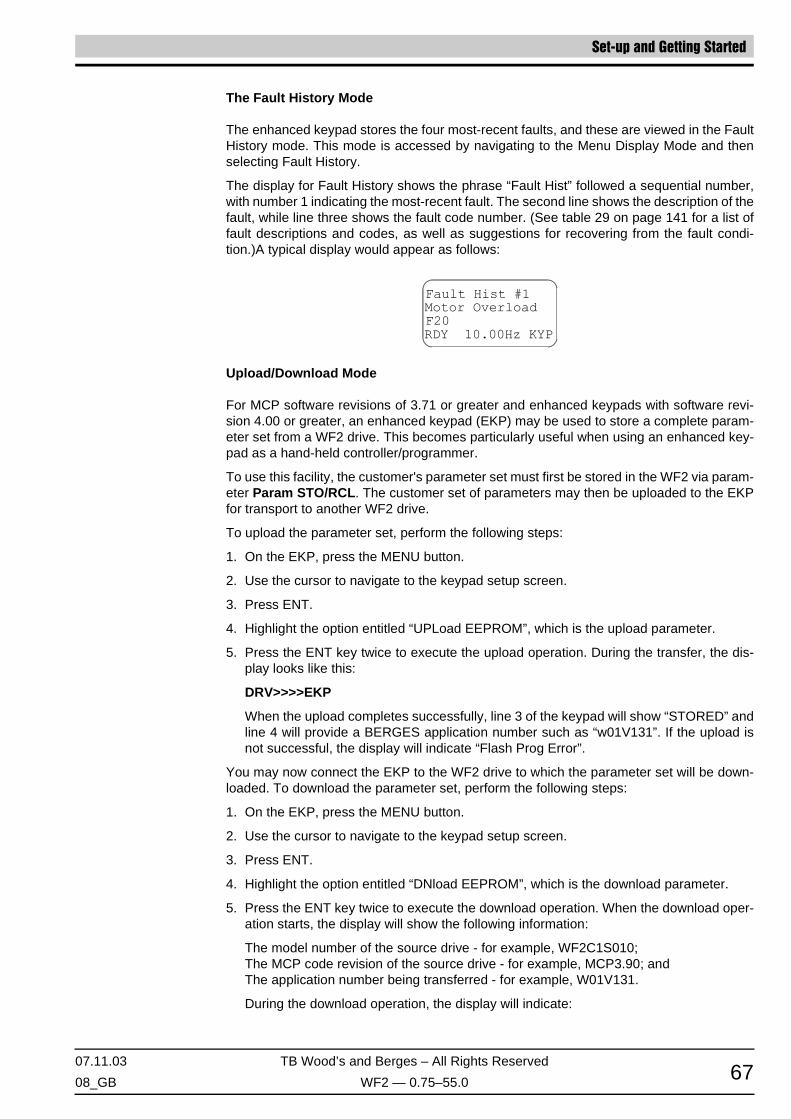
07.11.03 TB Wood’s and Berges – All Rights Reserved
08_GB WF2 — 0.75–55.0 67
Set-up and Getting Started
The Fault History Mode
The enhanced keypad stores the four most-recent faults, and these are viewed in the FaultHistory mode. This mode is accessed by navigating to the Menu Display Mode and thenselecting Fault History.
The display for Fault History shows the phrase “Fault Hist” followed a sequential number,with number 1 indicating the most-recent fault. The second line shows the description of thefault, while line three shows the fault code number. (See table 29 on page 141 for a list offault descriptions and codes, as well as suggestions for recovering from the fault condi-tion.)A typical display would appear as follows:
Upload/Download Mode
For MCP software revisions of 3.71 or greater and enhanced keypads with software revi-sion 4.00 or greater, an enhanced keypad (EKP) may be used to store a complete param-eter set from a WF2 drive. This becomes particularly useful when using an enhanced key-pad as a hand-held controller/programmer.
To use this facility, the customer's parameter set must first be stored in the WF2 via param-eter Param STO/RCL. The customer set of parameters may then be uploaded to the EKPfor transport to another WF2 drive.
To upload the parameter set, perform the following steps:
1. On the EKP, press the MENU button.
2. Use the cursor to navigate to the keypad setup screen.
3. Press ENT.
4. Highlight the option entitled “UPLoad EEPROM”, which is the upload parameter.
5. Press the ENT key twice to execute the upload operation. During the transfer, the dis-play looks like this:
DRV>>>>EKP
When the upload completes successfully, line 3 of the keypad will show “STORED” andline 4 will provide a BERGES application number such as “w01V131”. If the upload isnot successful, the display will indicate “Flash Prog Error”.
You may now connect the EKP to the WF2 drive to which the parameter set will be down-loaded. To download the parameter set, perform the following steps:
1. On the EKP, press the MENU button.
2. Use the cursor to navigate to the keypad setup screen.
3. Press ENT.
4. Highlight the option entitled “DNload EEPROM”, which is the download parameter.
5. Press the ENT key twice to execute the download operation. When the download oper-ation starts, the display will show the following information:
The model number of the source drive - for example, WF2C1S010;The MCP code revision of the source drive - for example, MCP3.90; andThe application number being transferred - for example, W01V131.
During the download operation, the display will indicate:

Set-up and Getting Started
TB Wood’s and Berges – All Rights Reserved 07.11.03
WF2 — 0.75–55.0 08_GB68
EKP>>>>DRV
6. Once the download operation is complete, activate the downloaded parameter set in thedestination drive by loading it from the stored customer set. To accomplish this, navigateto parameter Param STO/RCL and select “Load Param”. The downloaded parameterwill then become the active parameter set.
NOTE:
Some model specific adjustments may be required if the model number of the source anddestination drives are not identical.
6.4.4 LEDs on the Enhanced Keypad
The enhanced keypad features three LEDs to provide status information. The following ta-ble describes these three LEDS.
6.5 Security
6.5.1 Access Levels
The WF2 drive allows you to configure access levels to prevent unauthorized access. Twolevels of access are available:
• Configure Access – a user may read all WF2 parameters, and configure the non-read-only parameters, provided the drive is stopped. This is the default setting for access.
• Configure Run Access – a user may read all WF2 parameters, and configure the non-read-only parameters, whether the drive is running or stopped (although some parame-ters may only be configured if the drive is stopped).
An access level is assigned by setting the value of parameter Access Level found in theSecurity Group; see page 76 for more information on this parameter. The password (actu-ally, a four-digit “pass-number”) for the security level is set by parameter Set Password;see page 76.
6.5.2 Gaining Access when Security Enabled
Standard Keypad
When security is enabled and the PROG key or SHIFT+PROG keys are pressed to enterprogramming mode, all parameters (except the Enter Password parameter) will be locked.
To unlock the parameters that are available at the configured security level, pressSHIFT+PROG to initiate Level 2 programming and then navigate to the Enter Passwordparameter, which is in the Security Group.
Once this parameter is displayed, press the up or down key to set the displayed value tothe value of the password, and then press the Enter key.
LED Name Duration Operating Condition
POWER Continuous The drive is powered-up.
WARNING ContinuousAbnormal operation is detected, but the abnormality is not se-vere enough to cause a fault.
FAULT ContinuousAbnormal operation is detected, but the abnormality is greater than a warning. The drive will halt operation when a fault is de-tected.

07.11.03 TB Wood’s and Berges – All Rights Reserved
08_GB WF2 — 0.75–55.0 69
Set-up and Getting Started
After the Enter key is pressed, the drive compares the value of Enter Password with thatin the Set Password parameter. If they match, the user is granted access at the level setby the Access Level parameter. (If they do not match, access is granted, but with Read-Only status.)
Note that if the WF2 drive is power-cycled while the parameters are unlocked or if the Pro-gramming mode reverts to the Operate mode due to inactivity, the parameters will becomelocked again. You must re-enter the password to configure the settings of the accessibleparameters.
Enhanced Keypad
When a user attempts to navigate to the Parameter mode or Direct Parameter Accessmode, a prompt will appear asking for the password. Type the password and press ENTER.If the password is accepted, the desired mode is entered.
Note that if the WF2 drive is power-cycled while the parameters are unlocked or if the Pa-rameter mode or Direct Parameter Access mode reverts to the Operate mode due to inac-tivity, the parameters will become locked again. You must re-enter the password to config-ure the settings of the accessible parameters.
6.5.3 Disabling Security
Standard Keypad
To disable security, perform the following steps:
1. Unlock all available parameters.
This is accomplished by pressing SHIFT+PROG to initiate Level 2 programming andthen navigating to the Enter Password parameter. Once the parameter is displayed,use the up or down arrow keys to set the displayed value to the value of the password,and then press the Enter key. If the correct password is entered, all parameters at theconfigured security level will be available.
2. Navigate to the Set Password parameter, which is also in the Security Group. Set thedisplayed value of this parameter to zero, and then press the Enter key.
3. Navigate to the Enter Password parameter, which is also in the Security Group. Set thedisplayed value of this parameter to zero, and then press the Enter key.
4. Security is now disabled. All parameters, not just those of the configured security level,will be available for programming.
Enhanced Keypad
To disable security with the enhanced keypad, navigate to the Set Password parameter inthe Security group and set the value of this parameter to 0.
6.6 Control Paths
6.6.1 Overview of Control Paths
Control paths are the means for sending the frequency (speed) reference and start/stopcommands to the WF2 drive. The control path may be the same for both the frequency ref-erence and start/stop commands, or different paths may be used for each.
The WF2 drive provides three control paths: the keypad (either standard or enhanced), theterminal strip, and the serial link. The table below further elaborates these control paths.

Set-up and Getting Started
TB Wood’s and Berges – All Rights Reserved 07.11.03
WF2 — 0.75–55.0 08_GB70
You may determine which control paths are currently active by reading two parameters.These read-only parameters are Freq Ref Ctrl and Start Stop Ctrl; see page 80 for moreinformation on these parameters.
6.6.2 Selection of Control Paths
The WF2 drive provides two methods for selecting the control path for the frequency refer-ence and start/stop commands.
Method 1: Selection via Parameters Terminal/Keypad and Cntl Word 1
The first method is to set the Terminal/Keypad parameter to a value that corresponds tothe desired control path or override this parameter by setting bits 0 and/or 1 of parameterCntl Word 1 to 1 to allow the serial link to be used to select the control path.
As shown on page 85 where the Terminal/Keypad parameter is described, the first fourfunctions for this parameter allow you to select the control path directly (in the first two func-tions, the control path is the same for frequency reference and start/stop commands; thenext two functions permit different control paths for each):
Kypd-C & R: The keypad is both the source for control functions and for the referencefrequency. The Operate display on the keypad shows KYP to denote thisselection.
TS-C & R: Inputs to the terminal strip are the source for both control functions and thereference frequency. The Operate display on the keypad shows TRM todenote this selection.
KP-C/TS-R: The keypad is the source for control functions, while inputs to the terminalstrip are the source for the reference frequency. The Operate display onthe keypad shows KST to denote this selection.
TS-C/KP-R: Inputs to the terminal strip perform control functions, while the keypad isthe source for the reference frequency. The Operate display on the keypadshows TSK to denote this selection.
These four settings are particularly useful when the application does not require a controlpath that can be altered “on the fly”. They assign the control path for the reference frequen-cy and start/stop commands to either the keypad or the terminal strip, and this assignmentcannot be altered except by re-configuring the Terminal/Keypad parameter.
The remaining functions that may be configured for the Terminal/Keypad parameter permitgreater flexibility by allowing you to select the control path “on the fly”. These functions es-sentially configure a “switch” to select whether the keypad or the terminal strip is the controlpath. Note that this is an “either/or” selection - you cannot configure “mixed modes” as withthe two settings described earlier (TS-C/KP-R and KP-C/TS-R). The last three functionsthat may be assigned to the Terminal/Keypad parameter are:
Control Path Frequency Reference Start/Stop Commands
KeypadWhen in the Operate mode, the up and down keys are used to set the frequency.
When in the Operate mode, the FWD, REV, and STOP keys control the drive.
Terminal StripA combination of analog and digital inputs sets the frequency.
A combination of analog and digital control the drive.
Serial LinkCommands arriving via remote com-munications set the frequency.
Commands arriving via remote com-munications control the drive.
Table 26WF2 Control Paths

07.11.03 TB Wood’s and Berges – All Rights Reserved
08_GB WF2 — 0.75–55.0 71
Set-up and Getting Started
T/K by DI: A digital input is configured to switch between the keypad as the source forboth the reference frequency and start/stop commands and inputs to theterminal strip as the source for both the reference frequency and start/stopcommands. When the digital input is open or false, the control path is thekeypad; when the digital input is closed or true, the terminal strip is the con-trol path.
T/K by Fkey: A function key on the enhanced keypad is configured to switch the controlpath between the keypad and the terminal strip (see parameters F1 KeyConfig through F4 Key Config on page 129 for more information).
T/K by SerLnk: Serial communication is used to set bit 11 of parameter Cntl Word 1 to 0or 1. When bit 11 is set to 0, the control path is the keypad; when bit 11 isset to 1, the terminal strip is the control path.
The setting of parameter Terminal/Keypad may be overridden, which allows the serial linkto be used to select the control path. This is accomplished by writing to bits 0 and 1 of pa-rameter Cntl Word 1.
As described on page 133 where parameter Cntl Word 1 is described, Bit 0 determineshow the control path for start/stop commands is selected. When the bit is set to 0, the con-trol path for start/stop commands is selected using the means set by parameter Terminal/Keypad. When the bit is set to 1, the control path for start/stop commands is the serial link.
Similarly, Bit 1 determines how the control path for the reference frequency is selected.When the bit is set to 0, the control path for the reference frequency is selected using themeans set by parameter Terminal/Keypad. When the bit is set to 1, the control path for thereference frequency is the serial link.
If only one of the two bits is set to 1, the Operate display will show SLP to denote that theserial link is only partially the control path. If both bits are set to 1, the Operate display willshow SLC to denote that the serial link is entirely the control path.
Note that you may temporarily halt serial link control by configuring a digital input to performthe SLO (serial link override) function. When the configured digital input becomes true, thestatus of bits 0 and 1 are ignored, control via the serial link is halted, and the selection ofthe control path reverts to parameter Terminal/Keypad.
Method 2: Selection via Parameters Local/Remote, Local Config, and Remote Config
The second, alternate method is to set the Local/Remote parameter to a value other thanNone, with the other values for this parameter being the means to switch between Localand Remote modes. Once the means for switching modes is selected, the current modeand the settings of parameters Local Config and Remote Config determine the controlpath.
Note that if you use this method for specifying control paths, the SLO function is unavaila-ble.
As described on page 86 where the Local/Remote parameter is described, three meansare available to switch between Local and Remote modes:
L/R by DI: A digital input is configured to switch between Local and Remote modes.When the digital input is open or false, the drive is in Local mode; when thedigital input is closed or true, the drive is in Remote mode.
L/R by Fkey: A function key on the enhanced keypad is configured to switch between Lo-cal and Remote modes (see parameters F1 Key Config through F4 KeyConfig on page 129 for more information).
L/R by SerLnk: Serial communication is used to switch between Local and Remote modes.When Bit 10 of parameter Cntl Word 1 is set to 0, the drive is in Localmode; when Bit 10 is set to 1, the drive is in Remote mode.

Set-up and Getting Started
TB Wood’s and Berges – All Rights Reserved 07.11.03
WF2 — 0.75–55.0 08_GB72
The Operate display will show either LOC (Local) or REM (Remote) to denote what modeis currently active.
Once the drive is placed in Local or Remote mode, the settings of parameters Local Configand Remote Config (respectively) determine how the control path is selected.
As described on page 86, the following functions may be assigned to the Local Config pa-rameter to specify the control path:
Kypd-C&R: The keypad is the control path for both the reference frequency and start/stop commands.
Ser-C&R: The serial link is the control path for both the reference frequency and start/stop commands.
Nm-R/Ser-C: The control path for the reference frequency is as defined by parameterTerminal/Keypad, while the serial link is the control path for start/stopcommands.
Nm non-Ser: When Local mode is active, the control path for both reference frequencyand start/stop commands is set by the Terminal/Keypad parameter (al-though control via the serial link may be asserted if desired); when Remotemode is active, the serial link is used to select the control path and cannotbe overridden using the SLO bit of Cntl Word 1. (Note that this setting forc-es the Remote Config parameter to Serial Lnk.)
Similarly, as described on page 87, the following functions may be assigned to the RemoteConfig parameter to specify the control path:
TS-C&R: The terminal strip is the control path for both the reference frequency andstart/stop commands.
Kpd-R/TS-C: The terminal strip is the control path for start/stop commands, while thekeypad is the control path for the reference frequency.
TS-R/Kpd-C: The keypad is the control path for start/stop commands, while the terminalstrip is the control path for the reference frequency.
Nm-R/Ser-C: The control path for the reference frequency is as specified by the Termi-nal/Keypad parameter, while the serial link is the control path for start/stopcommands.
TS-C/Ser-R: The serial link is the control path for the reference frequency, while the ter-minal strip is the control path for start/stop commands.
Serial Lnk: When Local mode is active, the control path is set by the Terminal/Keypadparameter (although control via the serial link may be asserted if desired);when Remote mode is active, the serial link sets the control path and can-not be overridden using the SLO bit of Cntl Word 1. (This setting forces theLocal Config parameter to Nm non-Ser.)
6.7 Serial Link Communication
The WF2 drive provides a serial link to support remote communication. The serial link sup-ports ASCII or RTU communication utilizing Modbus protocol. Modbus functions 3, 6, and16 are supported by the WF2 drive.
In addition, DeviceNet®, Metasys N2, and Siemens P1 protocols are supported by the WF2drive. See page 145 for further information on the DeviceNet option. Consult BERGES formore information on the Siemens P1 and Metasys N2 options.
The communication interface is RS485, and allows up to 247 slaves to be connected to onemaster (with repeaters when the number of drops exceeds 31). The pin-out diagram for theModbus communication port is shown in Figure 21 on page 52.

07.11.03 TB Wood’s and Berges – All Rights Reserved
08_GB WF2 — 0.75–55.0 73
Set-up and Getting Started
6.7.1 Configuration of the Serial Link
The Communication parameter group contains the parameters that govern the baud rate,watchdog timer, and protocol selection for the serial interface. See page 131 for informationon the parameters in this parameter group.
All addresses from 1 to 247 are allowed for WF2 drives. Address 0 is a broadcast addressunderstood by all drives; however, no reply is returned for messages sent to this address.
6.7.2 Parameter Addresses
Each parameter is assigned a unique memory address to permit easy reading and config-uration. Section 7 and 11 list all WF2 parameters and the memory address assigned toeach.
Note that for the standard keypad, by default parameter addresses are not shown. Theymay be displayed by setting Show Param # to Enabled (see page 129). For the enhancedkeypad, addresses are always shown.
6.7.3 Drive Control via the Serial Link
As explained in Section 6.6 starting on page 69, the serial link may be configured to be thecontrol path for the reference frequency, for start/stop commands, or for both. This is ac-complished by setting Bit 0 and/or Bit 1 of parameter Cntl Word 1 to 1. See section 6.6 formore information.
When either of these bits are set to 1, the SLO (serial link override) function also becomesavailable, which is used to temporarily halt serial link control of the drive (see the next sec-tion for more information on the SLO function).
Once Bit 1 is set to 1, the reference frequency is determined by Bit 4 of parameter CntlWord 1. When this bit is set to 0, the value of parameter Ext Freq Ref 1 determines thereference frequency; when the bit is set to 1, the value of parameter Ext Freq Ref 2 deter-mines the reference frequency.
6.7.4 Override of Serial Link Control
You may temporarily halt serial link control by assigning a digital input to perform the SLO(serial link override) function. See page 110 for information on configuring digital inputs.
When the digital input assigned to the SLO function becomes true, the status of Bit 0 andBit 1 of parameter Cntl Word 1 are ignored, serial link control is halted, and the control pathreverts to that specified by parameter Terminal/Keypad.
Note that if serial link is explicitly assigned in either the Local Config or Remote Configparameter, the SLO function is not available. Should serial link control be lost, the drive willeither fault (if the Comm Timeout parameter is set; see page 132) or will continue runningat the last speed reference received.

Parameters
TB Wood’s and Berges – All Rights Reserved 07.11.03
WF2 — 0.75–55.0 08_GB74
7 Parameters
7.1 Introduction
The WF2 drive incorporates a large number of parameters that allow you to configure thedrive to meet the special requirements of your particular application. The parameters areorganized into groups of related functionality, and within the groups the parameters areidentified by a short, descriptive name.
As described in the previous chapter, the parameters may be broadly grouped into twotypes: those assigned a value (such as the minimum frequency) and those assigned a func-tion (such as the type of stop to be performed, either ramp or coast). The manner in whichthese two types are displayed is slightly different, as shown in figure 24 on page 57 (for thestandard keypad) and figure 29 on page 65 (for the enhanced keypad).
This chapter describes the available parameters, the groups in which they are located, andthe values or functions that may be assigned to them. Chapter 11 (starting on page 156)provides a summary of all parameters including their ranges and default values. This chap-ter also notes the memory address of each parameter, which is useful for serial communi-cation.
7.2 Parameter Groups
The WF2 drive provides 23 parameter groups, all of which are accessible with either thestandard or enhanced keypad (provided security conditions are met). (Note, however, thatthe last group – Seq Configure – only becomes available when parameter Application inthe Special parameter group is set to “Sequencer” to make the Sequencer application avail-able; see section 10 for more information on this application.)
In addition, for the standard keypad, a 24th group is also available. This group contains themost often needed parameters from the other 23 groups. This 24th group is available asLevel 1 Programming, with the remaining 23 groups are available as Level 2 Programming.See page 55 for more information on these two levels of programming.
The names of the parameter groups are shown in table 27 on page 75. Note that the orderin which the groups are shown in the table is from the first group displayed to the last, whichcorresponds to what is displayed as you scroll through the parameter groups with eitherkeypad. For the standard keypad, table 28 on page 75 lists the parameters found in the Lev-el 1 Programming group. Since these parameters are duplicates of those found in the other23 parameter groups, see the noted page number for the description of the parameter.

07.11.03 TB Wood’s and Berges – All Rights Reserved
08_GB WF2 — 0.75–55.0 75
Security Group Parameters
7.3 Security Group
This parameter group allows you to configure security for the drive. See page 68 for moreinformation on security.
If the Set Password parameter is set to a non-zero value, security is enabled and a usermust enter a password to gain entry. The Enter Password parameter is set by the user tothe value of the password, which is then compared to the value in the Set Password pa-rameter. If they match, access is granted.
◊ Range: 0–9999 Default: 0
DisplayOrder
DisplayedGroup Name
SeePage
DisplayOrder
DisplayedGroup Name
SeePage
1 Security 75 13 Braking Options 106
2 Drive ID 76 14 Digital Inputs 110
3 Drive Status 78 15 Analog Inputs 113
4 Input Status 81 16 Digital Outputs 117
5 Control Modes 83 17 Analog Outputs 120
6 Speed Reference 88 18 Fault Management 122
7 Ramps 92 19 Display Options 127
8 Preset Speeds 96 20 Special 130
9 Skip Freq 97 21 Communication 131
10 Torque Limits 98 22 PID Configure 135
11 Drive Output 100 23 Seq Configure 148
12 Motor Setup 103
Table 27The Parameter Groups for the WF2 Drive
DisplayOrder
ParameterName
SeePage
DisplayOrder
ParameterName
SeePage
1 Output Freq 78 11 Minimum Freq 88
2 Output Voltage 78 12 Maximum Freq 89
3 Output Current 78 13 Accel Time 1 92
4 Drive Load 78 14 Decel Time 1 92
5 Drive Temp 79 15 Preset Speed 1 96
6 DC Bus Voltage 79 16 Preset Speed 2 96
7 2-Wire/3-Wire 83 17 Preset Speed 3 96
8 Jog Mode 84 18 A1 Configure 113
9 Reverse Mode 85 19 R1 Configure 118
10 Terminal/Keypad 85 20 R2 Configure 118
Table 28Parameters Available in Level 1 Programming (Standard Keypad Only)
Enter Password Address: 0298

Parameters Drive ID Group
TB Wood’s and Berges – All Rights Reserved 07.11.03
WF2 — 0.75–55.0 08_GB76
If this parameter is set to a non-zero value, security is enabled. A user must enter the valueof this parameter in the Enter Password parameter to program the parameters that aremade available by the Access Level parameter.
◊ Range: 0–9999 Default: 0
The WF2 drive provides two levels of access. This parameter sets which access level isenabled, which in turn determines which parameter groups may be accessed and adjusted.
The functions that may be assigned to this parameter, and what each signifies, are shownbelow:
◊ Range: see table Default: Configure
7.4 Drive ID Group
This parameter group shows information about the WF2 drive including its serial numberand the versions of software installed.
This parameter displays the type of drive. The following values may be displayed for thisparameter:
◊ Range: – Default: –
This parameter contains the portion of the WF2 model number related to voltage and horse-power. The number has the format vvhhf, where vv is the code for the input voltage (19 =115 V AC singlephase; 29 = 230 V AC, single-phase; 20 = 230 V AC, three-phase; 40 = 460V AC, three-phase; 50 = 575 V AC, three-phase), hh is the horsepower, and f is the frac-tional part of the horsepower.
For example, 29010 indicates a 230 V AC, single-phase, 1.0 HP model.
◊ Range: 0–65535 Default: –
Set Password Address: 0299
Access Level Address: 0297
Display Function
ConfigureYou may read all parameters, and configure the non-read-only param-eters, if the drive is stopped.
Config Run
You may read all parameters, and configure the non-read-only param-eters, whether the drive is stopped or running, although some param-eters (such as those for digital inputs) may only be configured when the drive is stopped.
Drive Type (Read-Only) Address: 0999
Displayed Name Type of Drive
WF2C A constant-horsepower rated WF2 drive.
WF2K A constant-kilowatt rated WF2 drive.
WF2C(N) A constant-horsepower rated, NSF-certified WF2 drive.
WF2K(N) A constant-kilowatt rated, NSF-certified WF2 drive.
Catalog Number (Read-Only) Address: 0001
07.11.03 TB Wood’s and Berges – All Rights Reserved
08_GB WF2 — 0.75–55.0 77
Drive ID Group Parameters
This parameter contains a four-digit number that corresponds to the year and week in whichthe WF2 drive was manufactured.
◊ Range: 0–9952 Default: –
This parameter contains a four-digit number that is the remainder of the serial number (pa-rameter Serial No 1 is the first part of the number; see above).
◊ Range: 0–32767 Default: –
This parameter shows the version of the Motor Control Processing (MCP) program loadedin the WF2 drive.
◊ Range: 0.00–327.67 Default: –
This parameter shows the version of the user interface software loaded in the drive.
◊ Range: 0.00–327.67 Default: –
This parameter shows the version of the application software loaded in the WF2 drive.
◊ Range: 0.00–327.67 Default: –
When the temperature of the heatsink (as found in parameter Drive Temp; see page 79)exceeds the value set in parameter Drive Temp Lvl (see page 119), a warning will be giv-en. If the temperature exceeds the value set in this parameter (Drive Temp Trip), an over-temperature fault will occur and the drive will stop.
◊ Range: 0–125 °C Default: –
This parameter shows the nominal current of the WF2 drive.
◊ Range: 0–250 A Default: –
This parameter shows the type of communication option board attached to the WF2 drive.The following values may be displayed for this parameter:
Serial No 1 (Read-Only) Address: 0005
Serial No 2 (Read-Only) Address: 0006
MCP Sw Version (Read-Only) Address: 0007
TSP Sw Version (Read-Only) Address: 0009
Appl Sw Version (Read-Only) Address: 0010
Drive Temp Trip (Read-Only) Address: 0015
Drv Nom Current (Read-Only) Address: 0013
Comm Option (Read-Only) Address: 0003

Parameters Drive Status Group
TB Wood’s and Berges – All Rights Reserved 07.11.03
WF2 — 0.75–55.0 08_GB78
◊ Range: see table Default: –
This parameter shows whether an option board is attached to the WF2 drive by identifyingthe type of option board installed. The following values may be displayed for this parameter:
◊ Range: – Default: –
7.5 Drive Status Group
This parameter group contains parameters that are concerned with the basic operating val-ues of the WF2 drive and attached motor.
This parameter contains the frequency output to the motor. It is not modified by slip com-pensation (parameter Slip Comp; see page 102).
◊ Range: 0.00–320.00 Hz Default: –
This parameter shows the voltage being output to the motor.
◊ Range: 0 V to Line Voltage Default: –
This parameter contains the current output to the motor.
◊ Range: 0 to 250% of Drive Rating in Amps Default: –
This parameter shows the percentage of maximal load relative to the drive’s capacity.
◊ Range: –250%...+250% Default: –
Displayed Name Type of Communication Board
None A communication board is not attached to the WF2 drive.
DeviceNet A DeviceNet Option Board is attached to the WF2 drive.
Siemens P1 A Siemens P1 communication board is attached to the drive.
Metasys N2 A Metasys N2 communication board is attached to the drive.
Option Board (Read-Only) Address: 0004
Displayed Name Type of Option Board
None An option board is not attached to the WF2 drive.
WF2AIO-01 The WF2AIO-01 option board is attached to the drive.
Output Freq (Read-Only) Address: 0020
Output Voltage (Read-Only) Address: 0022
Output Current (Read-Only) Address: 0023
Drive Load (Read-Only) Address: 0024

07.11.03 TB Wood’s and Berges – All Rights Reserved
08_GB WF2 — 0.75–55.0 79
Drive Status Group Parameters
This parameter shows the actual temperature of the drive’s heatsink. Note that an overtem-perature fault will be generated when the heatsink temperature reaches the value of param-eter Drive Temp Trip (see page 77). If desired, you may configure a digital output to chan-ge state when the temperature exceeds the value of parameter Drive Temp Lvl – which,in effect, allows you to configure a warning of an impending overtemperature fault.
◊ Range: –20...125 °C Default: –
This parameter shows the DC bus voltage.
◊ Range: 0–1000 V DC Default: –
This parameter shows the estimated temperature of the motor as a percentage of the the-oretical thermal capacity of the motor. The estimated temperature and the thermal capacityare derived from a thermal model that utilizes the parameter values found in the Motor Set-up Group (see page 103) and on the estimated load on the motor.
◊ Range: 0–250 °C Default: –
This parameter shows the estimated torque being supplied to the motor as a percentage ofthe nominal motor torque. The estimation is based on the parameter values found in theMotor Setup Group (see page 103) and on the estimated load on the motor.
◊ Range: –250%...+250% Default: –
This parameter shows the estimated torque being supplied to the motor in Newton meters(Nm), with precision equal to 0.1 Nm. The estimation is based on the parameter valuesfound in the Motor Setup Group (see page 103) and on the estimated load on the motor.
◊ Range: varies Default: –
This parameter shows the power being delivered to the motor, which is derived from theparameter values of the Motor Setup group and the estimated load on the motor.
◊ Range: 0–250% Default: –
This parameter shows the speed reference that is currently in use. The source for the set-ting of the speed reference may be from the keypad, the terminal strip, or the serial link de-pending on the configuration of parameters Terminal/Keypad (see page 85) and Local/Remote (see page 86).
◊ Range: 0.00–320.00 Hz Default: –
Drive Temp (Read-Only) Address: 0025
DC Bus Voltage (Read-Only) Address: 0026
Motor Temp (Read-Only) Address: 0027
Out Torque (%) (Read-Only) Address: 0028
Out Torque (Nm) (Read-Only) Address: 0039
Output Power (Read-Only) Address: 0029
Active Spd Ref (Read-Only) Address: 0031

Parameters Drive Status Group
TB Wood’s and Berges – All Rights Reserved 07.11.03
WF2 — 0.75–55.0 08_GB80
This parameter contains the estimated current speed of the motor in revolutions per minute.The estimation is based on the parameter values found in the Motor Setup Group (see page103) and on the estimated load on the motor.
◊ Range: 0–5000 RPM Default: –
This parameter shows the active source for Start/Stop control. It is highly dynamic, andchanges as online conditions change. If you read this parameter via the serial link, 0 indi-cates the terminal strip; 1 indicates the keypad; and 2 indicates the serial link.
◊ Range: – Default: –
This parameter shows the active source for the setting of the reference frequency. It is high-ly dynamic, and changes as online conditions change. If you read this parameter via theserial link, 0 indicates the terminal strip; 1 indicates the keypad; and 2 indicates the seriallink.
◊ Range: – Default: –
These parameters work together to display the number of days that the WF2 drive has beenunder power. When this parameter is read from a keypad, the display will show the numberof days properly formatted. However, when the parameter is read via serial communication,you must also read parameter Drv Life Format to properly format the value. To format thevalue, divide the value shown for parameter Drive Lifetime by:
• 1 if parameter Drv Life Format is 50;• 10 if parameter Drv Life Format is 51; or• 100 if parameter Drv Life Format is 52.
The value of the Drive Lifetime parameter cannot be reset.
◊ Range: 0–65535 Drive Lifetime Default: –
◊ Range: 50, 51 or 52 Drv Life Format Default: –
These parameters work together to display the number of hours that the WF2 drive hasbeen operating. When this parameter is read from a keypad, the display will show thenumber of hours properly formatted. However, when the parameter is read via serial com-munication, you must also read parameter Runtime Format to properly format the value.To format the value, divide the value shown for parameter Elapsed Runtime by:
• 1 if parameter Runtime Format is 50;• 10 if parameter Runtime Format is 51; or• 100 if parameter Runtime Format is 52.
Motor RPM (Read-Only) Address: 0033
Start Stop Ctrl (Read-Only) Address: 0053
Freq Ref Ctrl (Read-Only) Address: 0054
Drive Lifetime (Read-Only) Address: 0890
Drv Life Format (Read-Only) Address: 0891
Elapsed Runtime (Read-Only) Address: 0892
Runtime Format (Read-Only) Address: 0893

07.11.03 TB Wood’s and Berges – All Rights Reserved
08_GB WF2 — 0.75–55.0 81
Input Status Group Parameters
The Elapsed Runtime parameter’s value may be reset by setting parameter ProgramNumber to 10.
◊ Range: 0–65535 Elapsed Runtime Default: –
◊ Range: 50, 51 or 52 Runtime Format Default: –
These parameters work together to display the amount of power that the WF2 drive hasconsumed over its lifetime. When this parameter is read from a keypad, the display willshow the amount of power consumed properly formatted. However, when the parameter isread via serial communication, you must also read parameter MWh Life Format to properlyformat the value. To format the value, divide the value shown for parameter MWh Lifetimeby:
• 10 if parameter MWh Life Format is 51;• 100 if parameter MWh Life Format is 52; or• 1000 if parameter MWh Life Format is 53.
The value of the MWh Lifetime parameter cannot be reset.
◊ Range: 0–65535 MWh Lifetime Default: –
◊ Range: 51, 52, or 53 MWh Life Format Default: –
These parameters work together to display the amount of power that the WF2 drive hasconsumed since parameter Elapsed MWh was reset. When this parameter is read from akeypad, the display will show the amount of power consumed properly formatted. However,when the parameter is read via serial communication, you must also read parameter MWhFormat to properly format the value. To format the value, divide the value shown for pa-rameter Elapsed MWh by:
• 10 if parameter MWh Format is 51;• 100 if parameter MWh Format is 52; or• 1000 if parameter MWh Format is 53.
The Elapsed MWh parameter’s value may be reset by setting parameter ProgramNumber to 20.
◊ Range: 0–65535 Elapsed MWh Default: –
◊ Range: 51, 52, or 53 MWh Format Default: –
7.6 Input Status Group
This parameter group provides status information about the various inputs to the drive.
MWh Lifetime (Read-Only) Address: 0894
MWh Life Format (Read-Only) Address: 0895
Elapsed MWh (Read-Only) Address: 0896
MWh Format (Read-Only) Address: 0897
D1 Status (Read-Only) Address: 0150
D2 Status (Read-Only) Address: 0151
D3 Status (Read-Only) Address: 0152
D4 Status (Read-Only) Address: 0153
D5 Status (Read-Only) Address: 0154

Parameters Input Status Group
TB Wood’s and Berges – All Rights Reserved 07.11.03
WF2 — 0.75–55.0 08_GB82
These eleven parameters show the status of the ten digital inputs and also the status of theenable circuit (the circuit connected to the EN terminal).
◊ Range: Off or On Default: –
This parameter contains a value representing the measured input signal at the A11 (analoginput 1) terminal as a percentage of the maximum input signal. For example, if A11 wasconfigured to range from 0 to 10 V DC and the measured voltage was 2 V, then this param-eter would show 20% (2/10).
◊ Range: –100%...+100% Default: –
This parameter contains a value representing the measured input signal at the A21 (analoginput 2) terminal as a percentage of the maximum input signal. For example, if A21 wasconfigured to range from 0 to 20 mA DC and the measured current was 15 mA, then thisparameter would show a value of 75% (15/20).
◊ Range: 0–100% Default: –
These five parameters show the status of the three digital outputs and also the status of thetwo output relays.
◊ Range: Off or On Default: –
This parameter contains a value representing the measured voltage at the A0 (analog out-put 1) terminal as a percentage of the maximum output voltage. For example, if this param-eter showed 50%, then the voltage being output at A0 would be 5 V DC (50% of 10 V DC,the maximum value).
◊ Range: 0–100% Default: –
D6 Status (Read-Only) Address: 0155
D7 Status (Read-Only) Address: 0156
D8 Status (Read-Only) Address: 0157
D9 Status (Read-Only) Address: 0158
D10 Status (Read-Only) Address: 0159
EN Status (Read-Only) Address: 0160
A1 Level (Read-Only) Address: 0164
A2 Level (Read-Only) Address: 0165
DQ1 Status (Read-Only) Address: 0167
DQ2 Status (Read-Only) Address: 0168
DQ3 Status (Read-Only) Address: 0169
R1 Status (Read-Only) Address: 0170
R2 Status (Read-Only) Address: 0171
AQ1 Level (Read-Only) Address: 0174

07.11.03 TB Wood’s and Berges – All Rights Reserved
08_GB WF2 — 0.75–55.0 83
Control Modes Group Parameters
This parameter contains a value representing the measured current at the A1 (analog out-put 2) terminal as a percentage of the maximum output current. For example, if this param-eter showed 25%, then the process output current at A1 would be 5 mA DC (if the currentrange was 0 to 20 mA DC) or 8 mA DC (if the current range was 4 to 20 mA DC). (The cur-rent range is selected with parameter AQ2 Output Type; see page 121.)
◊ Range: 0–100% Default: –
These parameters contain a value representing the measured input signal at the A, B, or Cterminal of the Analog Input/Output Option Board as a percentage of the maximum inputsignal. For example, if terminal AINC was configured to range from 0 to 20 mA DC and themeasured current was 5 mA, then this parameter would show a value of 25% (5/20).
◊ Range: 0–100% Default: –
These parameters contain a value representing the measured voltage at the A, B, or C ter-minal of the Analog Input/Output Option Board as a percentage of the maximum output volt-age. For example, if this parameter showed 70%, then the voltage being output at terminalAQB would be 7 V DC (70% of 10 V DC, the maximum value).
◊ Range: 0–100% Default: –
These parameters show the status of the two output relays found on the Analog Input/Out-put Option Board.
◊ Range: Off or On Default: –
7.7 Control Modes Group
This parameter group contains parameters that configure how the drive is controlled.
This parameter allows you to select whether 2-wire or 3-wire control will be used. See page40 for more information on 2-wire and 3-wire control including sample connection diagrams.Note that if 3-wire control is selected, digital input D2 is forced to act as a Stop input; it can-not be configured to perform another function. (See page 110 for more information on con-figuring the functionality of D2.) The following functions may be assigned to this parameter:
AQ2 Level (Read-Only) Address: 0175
AINA Level (Read-Only) Address: 0264
AINB Level (Read-Only) Address: 0269
AINC Level (Read-Only) Address: 0274
AQA Level (Read-Only) Address: 0278
AQB Level (Read-Only) Address: 0282
RA Status (Read-Only) Address: 0285
RB Status (Read-Only) Address: 0286
2-Wire/3-Wire Address: 0401

Parameters Control Modes Group
TB Wood’s and Berges – All Rights Reserved 07.11.03
WF2 — 0.75–55.0 08_GB84
◊ Range: see table Default: 2-Wire
This parameter allows you to select whether the drive will automatically start when line pow-er is applied (if a Run command is active from the terminal strip). The following functionsmay be assigned to this parameter:
◊ Range: see table Default: Line Str L
This parameter allows you to configure whether a ramp-to-stop or a coast-to-stop occurswhen a Stop command is issued. In a ramp-to-stop, the drive remains operational and mayassist in the stopping. In coast-to-stop, the drive turns off when the Stop command occurs,and the load stops at a rate determined by friction and inertia.
Instead of these two types of stopping, you may specify that direct current be applied justbefore the shaft stops turning (zero speed). The length of time that direct current is appliedis set by parameter DC Inj Time-Stp (see page 109). (Note that if DC Inj Time-Stp is setto zero, braking continues until the EN (enable) input is toggled.) The following functionsmay be assigned to this parameter:
◊ Range: see table Default: Rmp to Stp
This parameter allows you to configure whether jog operations will be allowed and the typeof jog control utilized. The following functions may be assigned to this parameter:
◊ Range: see table Default: No Jogging
Display Function
2-Wire 2-wire control is utilized.
3-Wire 3-wire control is utilized.
Start Mode Address: 0402
Display Function
Line Str LLine Start Lock-Out. The drive will not automatically start when line power is applied and a Run command is active. Instead, a new Run command must be given.
Auto StartThe drive will automatically start when line power is applied and a Run command is active.
Stop Mode Address: 0403
Display Function
Rmp to Stp A ramp-to-stop is performed.
Cst to Stp A coast-to-stop is performed.
DCI to Stp A DC pulse is applied near zero speed.
Jog Mode Address: 0404
Display Function
No Jogging Jogging is not configured.
Run/Jog DI A maintained-contact is used to initiate jogging; see page 42.
Jog PshbuttonA pushbutton is used to initiate jogging. See page 42 for more informa-tion.

07.11.03 TB Wood’s and Berges – All Rights Reserved
08_GB WF2 — 0.75–55.0 85
Control Modes Group Parameters
This parameter allows you to configure whether the drive may operate in Reverse and, ifso, how the direction is controlled. The following functions may be assigned to this param-eter:
◊ Range: see table Default: Non-revers
This parameter allows you to configure whether reference speed (Reference) and controlfunctions (Control) come from the keypad, inputs on the terminal strip, or a combination ofthe two. Settings are also provided for switching between the two control paths. See page69 for information on configuring control paths by using this parameter. The following func-tions may be assigned to this parameter:
Reverse Mode Address: 0405
Display Function
Non-reversThe drive cannot operate in Reverse; the REV key on the keypad is disabled.
For/Rev DIThe drive may operate in Reverse, but only via digital inputs. One dig-ital input initiates Run, and a second digital input selects the direction. See page 41 for more information.
Run FwdRev
The drive may operate in Reverse whether commanded from the key-pad or via digital inputs. One digital input initiates Run Forward, and a second digital input initiates Run Reverse. See page 41 for more infor-mation.
Terminal/Keypad Address: 0406
Display Function
Kypd-C & R
Keypad Control & Reference:The keypad is the source for both the reference speed (by the up and down keys) and control inputs (by the FWD, REV [if enabled], and STOP keys).
TS-C & RTerminal Strip Control & Reference:Inputs from the terminal strip set the reference speed and control op-eration.
TS-C/KP-RTerminal Strip Control & Keypad Reference:The reference speed is set from the keypad and operation is controlled by digital inputs of the terminal strip.
KP-C/TS-RKeypad Control & Terminal Strip Reference:The reference speed is set by inputs from the terminal strip, while the keys on the keypad control drive operation.
T/K by DITerminal Strip / Keypad Switching by DI:A digital input selects whether the keypad or the terminal strip is the source for control and the reference speed.
T/K by Fkey
Terminal Strip / Keypad Switching by Enhance Keypad FKey:Transfer of control and reference from the terminal strip to the keypad is accomplished by pressing the enhanced keypad function key (MON/F1, OPR/F2, PAR/F3, or DIR/F4) configured for this function; see page 129.

Parameters Control Modes Group
TB Wood’s and Berges – All Rights Reserved 07.11.03
WF2 — 0.75–55.0 08_GB86
◊ Range: see table Default: Kypd-C & R
This parameter determines whether Local and Remote modes will be active and how swit-ching between the two modes is accomplished. See page 70 for information on how Localand Remote modes may be used to determine control paths.
◊ Range: see table Default: None
This parameter sets the source for reference speed and control functions when Local modeis active (see the Local/Remote parameter on the previous page for more information).The following functions may be assigned to this parameter:
T/K SerLnk
Terminal Strip / Keypad Switching by Serial Link:Serial communication is used to set Bit 11 of parameter Cntl Word 1 (see page 133) to 0 or 1, with 0 selecting the keypad as the control path and 1 selecting the terminal strip as the control path.
Local/Remote Address: 0407
Display Function
NoneLocal and Remote modes are not used (parameters Terminal/Keypad and Cntl Word 1 determine the control path).
L/R by DI A digital input selects between Local and Remote modes.
L/R by FkeyTransfer of control between Local and Remote modes is accomplished by pressing the enhanced keypad function key (MON/F1, OPR/F2, PAR/F3, or DIR/F4) configured for this function; see page 129.
L/R SerLnkSerial communication is used to set Bit 10 of parameter Cntl Word 1 (see page 133) to 0 or 1, with 0 selecting Local mode and 1 selecting Remote mode.
Local Config Address: 0408
Display Function
Keypd-C&R
Keypad Control and Reference:The keypad is the source for both the reference speed (by the up and down keys) and control functions (by the FWD, REV [if enabled], and STOP keys).
Ser-C & R
Serial Link Control and Reference:Commands sent via serial communication initiate control functions and set the reference speed. Since the serial link is explicitly configured as the control path, the SLO (serial link override) function is not available.
Ser-C/Nm-RSerial Link Control and Keypad Reference:The up and down arrow keys on the keypad set the reference speed, while the control functions are commanded from the serial link.
Display Function

07.11.03 TB Wood’s and Berges – All Rights Reserved
08_GB WF2 — 0.75–55.0 87
Control Modes Group Parameters
◊ Range: see table Default: Keypd-C&R
This parameter sets the source for reference speed and control functions when Remotemode is active (see the Local/Remote parameter on page 86 for more information).The fol-lowing functions may be assigned to this parameter:
◊ Range: see table Default: TS-C & R
This parameter sets whether the “catch on the fly” feature is enabled. When it is enabled,a Run command will cause the drive to match its output to the speed of a freewheeling loadand then begin running. When the feature is disabled, a Run command causes the drive tostart from zero speed. The following functions may be assigned to this parameter:
Nm-non ser
Keypad or Serial Link Control and Reference:The keypad is the source for control functions and the reference speed.However, by setting bits 0 or 1 of Cntl Word 1 to 1, the control path may be switched to the serial link. The SLO function is also available for overriding serial link control.Note that if this setting is selected, the Remote Config parameter is automatically set to Serial Lnk.
Remote Config Address: 0409
Display Function
TS-C & RTerminal Strip Control & Reference:Inputs from the terminal strip set the reference speed and control op-eration.
Kpd-R/TS-CKeypad Reference and Terminal Strip Control:The reference speed is set from the keypad and operation is controlled by digital inputs.
TS-R/Kpd-CTerminal Strip Reference and Keypad Control:The reference speed is controlled by digital inputs and operation is set from the keypad.
NM-R/Ser-CNon-Serial Link Reference and Serial Link Control:The reference speed is set by either the keypad or terminal strip and operation is controlled by commands sent via serial communication.
TS-C/Ser-RSerial Link Reference and Terminal Strip Control:The reference speed is set via communication across the serial link and operation is controlled by inputs to the terminal strip.
Serial Lnk
Serial Link Control and Reference:Commands sent via serial communication initiate control functions and set the reference speed.Note that if this value is selected, the Local Config parameter is set to Nm - non ser.
Catch on Fly Address: 0620
Display Function

Parameters Speed Reference Group
TB Wood’s and Berges – All Rights Reserved 07.11.03
WF2 — 0.75–55.0 08_GB88
◊ Range: see table Default: Disabled
This parameter sets the type of stop that occurs when the drive is running under terminalstrip control and the STOP key on the keypad is pressed. The following functions may beassigned to this parameter:
◊ Range: see table Default: Cst to Stp
This parameter allows you to use the ENTER key on the keypad as a toggle switch betweendifferent control or operating states. The following functions may be assigned to this param-eter:
◊ Range: see table Default: Disabled
7.8 Speed Reference Group
This group contains parameters that allow you to configure the reference speed for thedrive as well as for jogging operations.
This parameter sets the minimum frequency that may be output to the motor. Note that theresolution is 1 Hz. Also note that if the value of this parameter is changed, the value of pa-rameters A1 Span and A2 Span will be affected as well. See pages 114 and 115 for moreinformation on these parameters.
◊ Range: 0 Hz to Maximum Freq Default: 0 Hz
Display Function
Disabled The drive will not perform a “catch on the fly”.
Enabled The drive will perform a “catch on the fly”.
Stop Key Address: 0950
Display Function
Disabled The STOP key is disabled.
Rmp to Stp A ramp-to-stop is performed.
Cst to Stp A coast-to-stop is performed.
Enter Key Address: 0978
Display Function
Disabled The ENTER key does not work as a toggle switch.
L/R Switch Switches between Local and Remote modes.
T/K Switch Switches the control path between the terminal strip and the keypad.
PID Enable Enables PID control.
SL Override Overrides serial link control.
Minimum Freq Address: 0301

07.11.03 TB Wood’s and Berges – All Rights Reserved
08_GB WF2 — 0.75–55.0 89
Speed Reference Group Parameters
This parameter sets the maximum frequency that may be output to the motor. Note that theresolution is 1 Hz. Also note that if the value of this parameter is changed, the value of pa-rameters A1 Span and A2 Span will be affected as well. See pages 114 and 115 for moreinformation on these parameters.
◊ Range: Minimum Freq to 320 Hz Default: 60 Hz
This parameter configures the reference speed for the drive. The reference speed resultsfrom inputs on the analog input terminals (A11/A12 and A21) and how parameters Ref1Config, Ref2 Config, and Ref3 Config are set; see page 90 for more information aboutthese three parameters.
◊ Range: see table Default: Spd - Rf 2
Maximum Freq Address: 0303
Main Speed Ref Address: 0800
Display Function
Spd - Rf 1 Reference 1.
Spd - Rf 2 Reference 2.
Spd - Rf 3 Reference 3.
Spd -R1+R2 The summation of references 1 and 2.
Spd -R1+R3 The summation of references 1 and 3.
S -R1+R2+R3 The summation of all references.
Spd -R2+R3 The summation of references 2 and 3.
S-R1+k*R2Reference 2 is scaled by factor k and then summed with reference 1. The value of k is set by parameter Set k-Factor (see page 92).
Spd-R1-R2 The difference between references 1 and 2.
Spd-R2-R1 The difference between references 2 and 1.
Spd-R1-R3 The difference between references 1 and 3.
Spd-R3-R1 The difference between references 3 and 1.
Spd-R2-R3 The difference between references 2 and 3.
Spd-R3-R2 The difference between references 3 and 2.
S-R1+R2-R3 The summation of references 1 and 2 less reference 3.
S-R1+R3-R2 The summation of references 1 and 3 less reference 2.
Spd-FixedThe speed reference is constant and is set by parameter Set Fixed Speed (see page 91).
8Bit DI PS
The speed reference is set by the binary word consisting of D3 through D10, with D3 being the least significant bit and D10 the most significant bit. All digital inputs must be properly configured for proper function. If a digital input is not configured, that input is considered inactive (0).The output frequency is computed by using the following formula to convert the 8-bit binary word (“8bbw” in the formula) into a decimal val-ue:
Spd-R1+R3 The summation of references 1 and 3.
Output Frequency 8bbwMax. Frequency Min. Frequency–
255------------------------------------------------------------------------------------------×=

Parameters Speed Reference Group
TB Wood’s and Berges – All Rights Reserved 07.11.03
WF2 — 0.75–55.0 08_GB90
This parameter configures the reference speed for jogging operations. As with the settingof the main reference speed for the drive, an analog input may be used to control joggingspeed.
◊ Range: see table Default: Spd-Fixed
These parameters establish which analog input sets the reference indicated in the param-eter name. The values that may be assigned to this parameter are as follows:
Jog Ref Config Address: 0803
Display Function
Spd - Rf 1 Reference 1.
Spd - Rf 2 Reference 2.
Spd - Rf 3 Reference 3.
Spd -R1+R2 The summation of references 1 and 2.
Spd -R1+R3 The summation of references 1 and 3.
S -R1+R2+R3 The summation of all references.
Spd -R2+R3 The summation of references 2 and 3.
S-R1+k*R2Reference 2 is scaled by factor k and then summed with reference 1. The value of k is set by parameter Set k-Factor (see page 92).
Spd-R1-R2 The difference between references 1 and 2.
Spd-R2-R1 The difference between references 2 and 1.
Spd-R1-R3 The difference between references 1 and 3.
Spd-R3-R1 The difference between references 3 and 1.
Spd-R2-R3 The difference between references 2 and 3.
Spd-R3-R2 The difference between references 3 and 2.
S-R1+R2-R3 The summation of references 1 and 2 less reference 3.
S-R1+R3-R2 The summation of references 1 and 3 less reference 2.
Spd-FixedThe speed reference is constant and is set by parameter Set Fixed Speed (see page 91).
8Bit DI PS
The speed reference is set by the binary word consisting of D3 through D10, with D3 being the least significant bit and D10 the most significant bit. All digital inputs must be properly configured for proper function. If a digital input is not configured, that input is considered inactive (0).The output frequency is computed by using the following formula to convert the 8-bit binary word (“8bbw” in the formula) into a decimal val-ue:
Ref1 Config Address: 0810
Ref2 Config Address: 0811
Ref3 Config Address: 0812
Output Frequency 8bbwMax. Frequency Min. Frequency–
255------------------------------------------------------------------------------------------×=

07.11.03 TB Wood’s and Berges – All Rights Reserved
08_GB WF2 — 0.75–55.0 91
Speed Reference Group Parameters
◊ Range: see table Ref1 Config Default: AI #1Ref2 Config Default: AI #2Ref3 Config Default: AI #2
The WF2 drive supports a variety of configurations for EMOP operation. The configurationsare based on whether the digital inputs on the terminal strip may be used to change theEMOP reference speed or whether the Up and Down Arrow keys on the digital keypad mayalso be used to change the EMOP reference speed. To use a digital input, configure twodigital inputs using the parameters in the Digital Inputs Group (see page 110).
In addition to configuring what controls the EMOP reference speed, you may configurewhether the reference speed is reset when a Stop or a power cycle occurs, or only when apower cycle occurs, or does not reset. If the reference speed is reset, the reference speedupon a re-start is the minimum frequency. The following functions may be assigned to thisparameter:
◊ Range: see table Default: None
When parameter Main Speed Ref or Jog Ref Config is set to Spd-Fixed, this parameterspecifies the speed.
◊ Range: 0.0–320.0 Hz Default: 5.0 Hz
Display Function
AI #1 Analog input 1 of the WF2 drive.
AI #2 Analog input 2 of the WF2 drive.
AI #A Analog input A of the Analog Input/Output Option Board.
AI #B Analog input B of the Analog Input/Output Option Board.
AI #C Analog input C of the Analog Input/Output Option Board.
EMOP Config Address: 0420
Display Function
None EMOP is not utilized.
TS no MemDigital inputs are used to change EMOP reference speed, and the EMOP reference speed is lost upon Stop or a power-cycle.
TS w/ MemDigital inputs are used to change EMOP reference speed, and the ref-erence speed is retained upon Stop but not when power is cycled.
TS w/ MemPDigital inputs are used to change EMOP reference speed, and the ref-erence speed is retained through a Stop or when power is cycled.
T/K no MemSame as TS no Mem except the keypad also may be used to change the EMOP reference speed.
T/K w/ MemSame as TS w/ Mem except the keypad also may be used to change the EMOP reference speed.
T/K MemPSame as TS w/ MemP except the keypad also may be used to change the EMOP reference speed.
Set Fixed Speed Address: 0804

Parameters Ramps Group
TB Wood’s and Berges – All Rights Reserved 07.11.03
WF2 — 0.75–55.0 08_GB92
When Main Speed Ref is set to S-R1+k*R2, this parameter sets the value of k, which is thescale factor by which reference 2 is multiplied before being added to reference 1.
◊ Range: 0.0–100.0% Default: 10.0%
7.9 Ramps Group
This parameter group provides access to the parameters concerned with establishing thevarious acceleration and deceleration ramps of the drive. (The drive supports three rampsplus a jogging ramp.) Parameters are also available to set the shape of the ramps.
This parameter sets the length of time to accelerate from 0 Hz to the maximum frequency(parameter Maximum Freq) for the primary ramp.
◊ Range: 0.1–3200.0 s Default: 3.0 s
This parameter sets the length of time to decelerate from the maximum frequency (param-eter Maximum Freq) to 0 Hz for the primary ramp.
◊ Range: 0.1–3200.0 s Default: 3.0 s
This parameter sets the length of time to accelerate from 0 Hz to the maximum frequency(parameter Maximum Freq) for Alternate Ramp 1.
◊ Range: 0.1–3200.0 s Default: 1.0 s
This parameter sets the length of time to decelerate from the maximum frequency (param-eter Maximum Freq) to 0 Hz for Alternate Ramp 1.
◊ Range: 0.1–3200.0 s Default: 1.0 s
This parameter sets the length of time to accelerate from 0 Hz to the maximum frequency(parameter Maximum Freq) for Alternate Ramp 2.
◊ Range: 0.1–3200.0 s Default: 10.0 s
This parameter sets the length of time to decelerate from the maximum frequency (param-eter Maximum Freq) to 0 Hz for Alternate Ramp 2.
◊ Range: 0.1–3200.0 s Default: 10.0 s
Set k-Factor Address: 0801
Accel Time 1 Address: 0310
Decel Time 1 Address: 0311
Accel Time 2 Address: 0312
Decel Time 2 Address: 0313
Accel Time 3 Address: 0314
Decel Time 3 Address: 0315

07.11.03 TB Wood’s and Berges – All Rights Reserved
08_GB WF2 — 0.75–55.0 93
Ramps Group Parameters
This parameter sets the length of time for acceleration (0 Hz to the EMOP reference speed)and deceleration (EMOP reference speed to 0 Hz) when EMOP is active.
◊ Range: 0.1–200.0 s Default: 30.0 s
This parameter selects when Alternate Ramp 1 (AR1) is invoked. Parameters Accel Time2 and Decel Time 2 (see page 92 for information on these parameters) configure the slopeof the ramp, while AR1 Ramp Type determines the shape of the ramp (see page 94). Thefollowing functions may be assigned to this parameter:
◊ Range: see table Default: AR1 on DI
This parameter selects when Alternate Ramp 2 (AR2) is invoked. Parameters Accel Time3 and Decel Time 3 (see page 92 for information on these parameters) configure the slopeof the ramp, while AR2 Ramp Type determines the shape of the ramp (see below). Thefollowing functions may be assigned to this parameter:
EMOP Ramp Time Address: 0316
AR1 Configure Address: 0450
Display Function
None AR1 is not available.
AR1 on DIA digital input is used to select AR1. While the input is true, AR1 is in use.
AR1 by Frq
When the drive reaches a preset frequency, AR1 is invoked and re-mains in effect until the frequency drops below the threshold. The fre-quency is set by parameter AR1 Switch Freq; see page 95 for more information.
AR1-Strt
When a Start command occurs, AR1 is invoked and remains in effect until the reference speed is reached. Once an At Speed condition is at-tained, the main ramp is used for reference changes. When a Stop command occurs, AR1 is invoked and remains in effect until zero speed is reached.
AR1-Fwd/RvWhen the drive begins operation in Reverse, AR1 is invoked and re-mains in effect until the direction changes.
AR2 Configure Address: 0451
Display Function
None AR2 is not available.
AR2 on DIA digital input is used to select AR2. While the input is true, AR2 is in use.
AR2 by Frq
When the drive reaches a preset frequency, AR2 is invoked and re-mains in effect until the frequency drops below the threshold. The fre-quency is set by parameter AR2 Switch Freq; see page 95 for more information.
AR2-Strt
When a Start command occurs, AR2 is invoked and remains in effect until the reference speed is reached. Once an At Speed condition is at-tained, the main ramp is used for reference changes. When a Stop command occurs, AR2 is invoked and remains in effect until zero speed is reached.

Parameters Ramps Group
TB Wood’s and Berges – All Rights Reserved 07.11.03
WF2 — 0.75–55.0 08_GB94
◊ Range: see table Default: AR2 on DI
This parameter determines the shape of the primary ramp determined by parameters AccelTime 1 and Decel Time 1. The following functions may be assigned to this parameter:
◊ Range: see table Default: Linear
If parameter Main Ramp Type is set to S-Curve, this parameter sets the amount of curva-ture at either end of the ramp. A value of 0 s produces a linear curve, while a value of 10 sproduces a maximally rounded S-shaped curve.
◊ Range: 0.0–10.0 s Default: 0.0 s
This parameter determines the shape of Alternate Ramp 1 (AR1). The following functionsmay be assigned to this parameter:
◊ Range: see table Default: Linear
If parameter AR1 Ramp Type is set to S-Curve, this parameter determines the amount ofcurvature at either end of the ramp. A value of 0 s produces a linear curve, while a value of10 s produces a maximally rounded S-shaped curve.
◊ Range: 0.0–10.0 s Default: 0.0 s
AR2-Fwd/RvWhen the drive begins operation in Reverse, AR2 is invoked and re-mains in effect until the direction changes.
Main Ramp Type Address: 0452
Display Function
Linear The shape of the ramp is a straight line.
S-CurveThe shape of the ramp is curved at the beginning and end, with the middle portion linear. The degree of curvature is set by parameter Main S-Rounding (see the next page).
Main S-Rounding Address: 0453
AR1 Ramp Type Address: 0454
Display Function
Linear The shape of the ramp is a straight line.
S-CurveThe shape of the ramp is curved at the beginning and end, with the middle portion linear. The degree of curvature is set by parameter AR1 S-Rounding (see below).
AR1 S-Rounding Address: 0455
Display Function

07.11.03 TB Wood’s and Berges – All Rights Reserved
08_GB WF2 — 0.75–55.0 95
Ramps Group Parameters
This parameter sets the frequency reference during acceleration and deceleration when theAR1 ramp is active. Note that it is accurate to the hundredths place (0.01), and that if set to0.00 the reference frequency defaults to the value of parameter Maximum Freq.
◊ Range: 0.00–320.00 Hz Default: 0.00 Hz
This parameter determines the shape of Alternate Ramp 2 (AR2). The following functionsmay be assigned to this parameter:
◊ Range: see table Default: Linear
If parameter AR2 Ramp Type is set to S-Curve, this parameter determines the amount ofcurvature at either end of the ramp. A value of 0 s produces a linear curve, while a value of10 s produces a maximally rounded S-shaped curve.
◊ Range: 0.0–10.0 s Default: 0.0 s
This parameter sets the frequency reference during acceleration and deceleration when theAR2 ramp is active. Note that it is accurate to the hundredths place (0.01), and that if set to0.00 the reference frequency defaults to the value of parameter Maximum Freq.
◊ Range: 0.00–320.00 Hz Default: 0.00 Hz
This parameter sets the acceleration time during jogging operations.
◊ Range: 0.0–3200.0 Hz Default: 1.0 Hz
This parameter sets the deceleration time during jogging operations.
◊ Range: 0.0–3200.0 Hz Default: 1.0 Hz
This parameter sets the frequency reference range during which the acceleration or decel-eration time is active. For example, if this parameter is set to 30 Hz and the accelerationtime is set to 10 s, then the acceleration ramp will have the slope of a 30 Hz increase in 10 s.
AR1 Switch Freq Address: 0462
AR2 Ramp Type Address: 0456
Display Function
Linear The shape of the ramp is a straight line.
S-CurveThe shape of the ramp is curved at the beginning and end, with the middle portion linear. The degree of curvature is set by parameter AR2 S-Rounding (see below).
AR2 S-Rounding Address: 0457
AR2 Switch Freq Address: 0464
Jog Accel Time Address: 0458
Jog Decel Time Address: 0459
Ramp Ref Frq Address: 0460

Parameters Preset Speeds Group
TB Wood’s and Berges – All Rights Reserved 07.11.03
WF2 — 0.75–55.0 08_GB96
Note that it is accurate to the hundredths place (0.01), and that if set to 0.00, the referencefrequency range is the difference between parameter Maximum Freq and parameter Min-imum Freq. For example, if the minimum frequency was 20 Hz and the maximum was 60Hz, then the acceleration and deceleration times correspond to the lengths of time to accel-erate or decelerate by 40 Hz (60 minus 20 Hz).
For most applications, it is recommended that this parameter be left at its default value of0.00 Hz.
◊ Range: 0.00–320.00 Hz Default: 0.00 Hz
7.10 Preset Speeds Group
This parameter group provides access to the parameters used to configure the preset ref-erence speeds for the drive. A preset speed is selected via a combination of digital inputsor by setting the bits of the control word appropriately (see page 45 for more information).
This parameter sets the first (of seven) preset speed. The speed is selected by a combina-tion of digital inputs or settings of bits 5, 6, and 7 in parameter Cntl Word 1; see page 45for a discussion of preset speeds and how each is selected.
◊ Range: 0.00 Hz to Maximum Freq Default: 5.00 Hz
This parameter sets the second (of seven) preset speed. The speed is selected by a com-bination of digital inputs or settings of bits 5, 6, and 7 in parameter Cntl Word 1; see page45 for a discussion of preset speeds and how each is selected.
◊ Range: 0.00 Hz to Maximum Freq Default: 10.00 Hz
This parameter sets the third (of seven) preset speed. The speed is selected by a combi-nation of digital inputs or settings of bits 5, 6, and 7 in parameter Cntl Word 1; see page 45for a discussion of preset speeds and how each is selected.
◊ Range: 0.00 Hz to Maximum Freq Default: 20.00 Hz
This parameter sets the fourth (of seven) preset speed. The speed is selected by a combi-nation of digital inputs or settings of bits 5, 6, and 7 in parameter Cntl Word 1; see page 45for a discussion of preset speeds and how each is selected.
◊ Range: 0.00 Hz to Maximum Freq Default: 30.00 Hz
This parameter sets the fifth (of seven) preset speed. The speed is selected by a combina-tion of digital inputs or settings of bits 5, 6, and 7 in parameter Cntl Word 1; see page 45for a discussion of preset speeds and how each is selected.
◊ Range: 0.00 Hz to Maximum Freq Default: 40.00 Hz
Preset Speed 1 Address: 0350
Preset Speed 2 Address: 0352
Preset Speed 3 Address: 0354
Preset Speed 4 Address: 0356
Preset Speed 5 Address: 0358

07.11.03 TB Wood’s and Berges – All Rights Reserved
08_GB WF2 — 0.75–55.0 97
Skip Freq Group Parameters
This parameter sets the sixth (of seven) preset speed. The speed is selected by a combi-nation of digital inputs or settings of bits 5, 6, and 7 in parameter Cntl Word 1; see page 45for a discussion of preset speeds and how each is selected.
◊ Range: 0.00 Hz to Maximum Freq Default: 50.00 Hz
This parameter sets the seventh (last) preset speed. The speed is selected by a combina-tion of digital inputs or settings of bits 5, 6, and 7 in parameter Cntl Word 1; see page 45for a discussion of preset speeds and how each is selected.
◊ Range: 0.00 Hz to Maximum Freq Default: 60.00 Hz
7.11 Skip Freq Group
This group contains parameters that allow you to configure up to five frequency bands thatare “skipped” during drive operation. The WF2 drive will not establish a steady-state at anyfrequency within a skip band; instead, it will ramp through the band.
This parameter sets the lower frequency of the first frequency band to be skipped.
◊ Range: 0.0 Hz to Maximum Freq Default: 0.0 Hz
This parameter sets the upper frequency of the first frequency band to be skipped.
◊ Range: Skip 1 Low Lim to Maximum Freq Default: 0.0 Hz
This parameter sets the lower frequency of the second frequency band to be skipped.
◊ Range: 0.0 Hz to Maximum Freq Default: 0.0 Hz
This parameter establishes the upper frequency of the second frequency band to beskipped.
◊ Range: Skip 2 Low Lim to Maximum Freq Default: 0.0 Hz
This parameter establishes the lower frequency of the third frequency band to be skipped.
◊ Range: 0.0 Hz to Maximum Freq Default: 0.0 Hz
Preset Speed 6 Address: 0360
Preset Speed 7 Address: 0362
Skip 1 Low Lim Address: 0480
Skip 1 Hi Lim Address: 0481
Skip 2 Low Lim Address: 0482
Skip 2 Hi Lim Address: 0483
Skip 3 Low Lim Address: 0484

Parameters Torque Limits Group
TB Wood’s and Berges – All Rights Reserved 07.11.03
WF2 — 0.75–55.0 08_GB98
This parameter establishes the upper frequency of the third frequency band to be skipped.
◊ Range: Skip 3 Low Lim to Maximum Freq Default: 0.0 Hz
This parameter establishes the lower frequency value of the fourth frequency band to beskipped.
◊ Range: 0.0 Hz to Maximum Freq Default: 0.0 Hz
This parameter establishes the upper frequency value of the fourth frequency band to beskipped.
◊ Range: Skip 4 Low Lim to Maximum Freq Default: 0.0 Hz
This parameter establishes the lower frequency value of the fifth frequency band to beskipped.
◊ Range: 0.0 Hz to Maximum Freq Default: 0.0 Hz
This parameter establishes the upper frequency value of the fifth frequency band to beskipped.
◊ Range: Skip 5 Low Lim to Maximum Freq Default: 0.0 Hz
7.12 Torque Limits Group
This group contains parameters that allow you to configure the torque limits for the drive.Limits may be set for both forward and reverse operation as well as for pulling a load (“mo-toring”) or being pulled by a load (“regenerative”).
For some applications, it is of benefit to limit the current output of the drive.This parameterallows you to limit the current output by configuring the maximum motor current from thedrive expressed as a percentage of nominal current rating.
◊ Range: 1–200% Default: 150%
The WF2 drive provides a Torque Limit feature. When this feature is enabled, the drive'sfrequency is automatically reduced when operating in motoring mode to keep the measuredtorque within limits. When operating in regenerative mode, the output frequency may be au-tomatically increased for the same reason.
Skip 3 Hi Lim Address: 0485
Skip 4 Low Lim Address: 0486
Skip 4 Hi Lim Address: 0487
Skip 5 Low Lim Address: 0488
Skip 5 Hi Lim Address: 0489
Current Limit Address: 0331
Trq Limit Type Address: 0601

07.11.03 TB Wood’s and Berges – All Rights Reserved
08_GB WF2 — 0.75–55.0 99
Torque Limits Group Parameters
Note that in addition to the torque limit parameters that activate the Torque Limit mode, twoadditional torque limits are available. These are Torque Level 1 and Torque Level 2 (seepage 119), and you may configure a digital output to become true when either of these limitsis exceeded (see page 117 for information on the parameters that configure the digital out-puts).
This parameter (Trq Limit Type) establishes how the feature will be enabled. The followingfunctions may be assigned to this parameter:
◊ Range: see table Default: Disabled
This parameter sets the torque limiting point when the drive is in motoring mode in the For-ward direction. The limit is expressed as a percentage of the torque load.
◊ Range: 1–200% Default: 150%
This parameter sets the torque limiting point when the drive is in regenerative mode in theForward direction. The limit is expressed as a percentage of the torque load.
◊ Range: 1–200% Default: 80%
This parameter sets the torque limiting point when the drive is in motoring mode in the Re-verse direction. The limit is expressed as a percentage of the torque load.
◊ Range: 1–200% Default: 150%
Display Function
Disabled Torque limiting will not be used.
Fixed Lvls
When the measured torque exceeds the limit set by either Trq Lim Mtr Fwd, Trq Lim Reg Fwd, Trq Lim Mtr Rev, or Trq Lim Reg Rev (de-pending on what the motor and drive are doing), torque limiting is ena-bled. See page 99 for a description of these parameters.
By DITorque limiting is enabled when a digital input is true. See page 98 for information on configuring a digital input to limit torque.
Follow AI
The analog input identified in parameter Trq Lim AI (see page 100) is monitored and as it changes, so does the value of each of the four torque limits named for Fixed Lvls. The values of the limits are found by multiplying the percentage of full-scale being input on the analog in-put by the configured torque limits. For example, if Trq Lim Mtr Fwd is set to 150% and A2 is at half-scale, then the actual torque limit when motoring forward is 75%.
On FreqWhen the drive’s output frequency is greater than the value set by Trq Lim Freq (see page 100), torque limiting is enabled.
Trq Lim Mtr Fwd Address: 0332
Trq Lim Reg Fwd Address: 0333
Trq Lim Mtr Rev Address: 0334

Parameters Drive Output Group
TB Wood’s and Berges – All Rights Reserved 07.11.03
WF2 — 0.75–55.0 08_GB100
This parameter sets the torque limiting point when the drive is in regenerative mode in theReverse direction. The limit is expressed as a percentage of the torque load.
◊ Range: 1–200% Default: 80%
When parameter Trq Limit Type is set to On Freq, the Torque Limit feature will activatewhen a certain frequency threshold is exceeded. This parameter, Trq Lim Freq, sets thethreshold frequency.
◊ Range: 0.0–320.0 Hz Default: 0.0 Hz
When parameter Trq Limit Type is set to Follow AI, an analog input is used to set thetorque limits. This parameter, Trq Lim AI, sets which analog input will be used. The follow-ing values may be assigned to this parameter.
◊ Range: see table Default: AI #1
This parameter sets the limit for the amount of time that the drive may continue to run inregenerative current limit after a Stop command is issued. If the configured time durationexpires and the drive is not yet at zero speed, Fault 59 (Regen Timeout) occurs and thedrive coasts to a stop.
◊ Range: 0–60 s Default: 1 s
7.13 Drive Output Group
This group contains parameters that allow you to configure the SVC and V/Hz algorithmsused in the drive. Figure 30 on page 101 shows how the parameters of this group determinea V/Hz curve.
Trq Lim Reg Rev Address: 0335
Trq Lim Freq Address: 0602
Trq Lim AI Address: 0603
Display Function
AI #1 Analog input 1 of the WF2 drive.
AI #2 Analog input 2 of the WF2 drive.
AI #A Analog input A of the Analog Input/Output Option Board.
AI #B Analog input B of the Analog Input/Output Option Board.
AI #C Analog input C of the Analog Input/Output Option Board.
Regen Timeout Address: 0605

07.11.03 TB Wood’s and Berges – All Rights Reserved
08_GB WF2 — 0.75–55.0 101
Drive Output Group Parameters
This parameter selects the control algorithms used by the WF2 drive. The following func-tions may be assigned to this parameter (note that all SVC control modes require optimumsetup of motor parameters; see section 7.14 [Motor Setup Group] on page 103 for moreinformation):
◊ Range: see table Default: CT - V/Hz 2pc
Figure 30How a V/Hz Curve Is Determined
Torque Type Address: 0500
Display Function
CT - SVCSensorless vector control (SVC), constant torque characteristic. This setting forces Set V-Boost and Slip Comp parameters to Automatic, and they cannot be set to another function.
VT - SVCVariable torque with SVC-type quadratic voltage characteristic. This setting forces Set V-Boost and Slip Comp parameters to Automatic, and they cannot be set to another function.
CT - SVC 2pc
Constant torque with SVC-type two-piece voltage characteristic. This setting forces Set V-Boost and Slip Comp parameters to Automatic. However, parameter V-Boost Config may be set to provide additional starting torque, with parameters Boost Taper Frq and Boost Taper Vlt defining the point on the theoretical curve where boost ceases.
CT - V/Hz
Constant torque with V/Hz control and linear voltage characteristic. Pa-rameter Set V-Boost is set to None, but may be changed to Automatic (with boost ceasing at the field weakening point). Parameter Slip Comp is set to None, but may be changed to Automatic.
VT - V/Hz
Variable torque with V/Hz control and quadratic voltage characteristic. Parameter Set V-Boost is set to Automatic, but may be changed to None (with boost ceasing at the field weakening point). Parameter Slip Comp is set to None, but may be changed to Automatic.
CT - V/Hz 2pc
Constant torque with V/Hz linear two-piece voltage characteristic. Pa-rameter Set V-Boost is set to Automatic, but it may be changed to None (with parameters Boost Taper Frq and Boost Taper Vlt defin-ing the point on the theoretical curve where boost ceases). Parameter Slip Comp is set to None, but may be changed to Automatic.
Nom Mtr Voltage
Boost Taper Vlt
V-Boost Config
Boost Taper Frq Nom Mtr Freq
Voltage
Frequency

Parameters Drive Output Group
TB Wood’s and Berges – All Rights Reserved 07.11.03
WF2 — 0.75–55.0 08_GB102
This parameter configures the switching (or carrier) frequency for the drive. Lower frequen-cies produce better torque, but produce more audible noise from the motor. Higher switch-ing frequencies produce less audible noise, but cause more heating in the drive and motor.The factory default setting for a particular model is the frequency rated to produce continu-ous full-load current within rated temperatures.
◊ Range: 1.0–16.0 kHz Default: varies
This parameter allows you to enable or disable the auto-carrier feature. When enabled, thesetting of the Carrier Freq parameter is ignored. Instead, the drive uses the optimumswitching frequency, which is the highest frequency for the load that does not cause over-heating.
◊ Range: see table Default: Disabled
This parameter sets the amount of slip compensation, which may provide more constantmotor speed under changing load conditions. The following functions may be assigned tothis parameter:
◊ Range: see table Default: None
This parameter sets the amount of boost (expressed as a percentage of nominal motor volt-age) to be applied at zero frequency. The amount configured then tapers linearly as fre-quency increases, reaching zero at the point specified by parameters Boost Taper Frq andBoost Taper Vlt.
The default values are model dependent:
Carrier Freq Address: 0501
Auto-Carrier Address: 0502
Display Function
Disabled Function auto-carrier is disabled.
Enabled Function auto-carrier is enabled.
Slip Comp Address: 0551
Display Function
None Slip compensation is not utilized.
AutomaticThe drive calculates how much slip compensation is needed depend-ing on the load and motor speed.
V-Boost Config Address: 0553
Model Number Default Model Number Default Model Number Default
WF2K2S00-7x 2.0% WF2K4000-7x 2.0% WF2K5000-7x 2.0%
WF2K2S01-5x 1.5% WF2K4001-5x 1.5% WF2K5001-5x 1.5%
WF2K2S02-2x 1.5% WF2K4002-2x 1.5% WF2K5002-2x 1.5%
WF2K2000-7x 2.0% WF2K4003-7x 1.5% WF2K5003-7x 1.5%
WF2K2001-5x 1.5% WF2K4005-5x 1.0% WF2K5005-5x 1.0%

07.11.03 TB Wood’s and Berges – All Rights Reserved
08_GB WF2 — 0.75–55.0 103
Motor Setup Group Parameters
◊ Range: 0.00–30.00% Default: varies
This parameter determines whether a voltage boost is applied. Voltage boost is the amountof voltage added at zero frequency (expressed as a percentage of nominal motor voltage),which is the start of the V/Hz curve. The boost tapers linearly to zero at the point set in pa-rameters Boost Taper Frq and Boost Taper Vlt (see below):
◊ Range: see table Default: None
This parameter works with the Set V-Boost parameter. When voltage boost is applied atthe start of the V/Hz curve, the amount of boost tapers linearly and reaches zero at the pointestablished by the frequency set in this parameter and the voltage set in parameter BoostTaper Vlt (see below).
◊ Range: 0.00 Hz to Maximum Freq Default: 60.00 Hz
This parameter works with the Set V-Boost parameter. When voltage boost is applied atthe start of the V/Hz curve, the amount of boost tapers linearly and reaches zero at the pointestablished by the voltage set in this parameter and the frequency set in parameter BoostTaper Frq (see above).
◊ Range: 0.00–100.00% Default: varies
7.14 Motor Setup Group
This group contains parameters that allow you to configure aspects of the motor attachedto the WF2 drive such as nominal motor current and voltage.
WF2K2002-2x 1.5% WF2K4007-5x 1.0% WF2K5007-5x 1.0%
WF2K2003-7x 1.5% WF2K4011-0x 1.0% WF2K5011-0x 1.0%
WF2K2005-5x 1.0% WF2K4015-0x 1.0% WF2K5015-0x 1.0%
WF2K2007-5x 1.0% WF2K4018-5x 0.5% WF2K5018-5x 0.5%
WF2K2011-0x 1.0% WF2K4022-0x 0.5% WF2K5022-0x 0.5%
WF2K2015-0x 1.0% WF2K4030-0x 0.5% WF2K5030-0x 0.5%
WF2K2018-5x 1.0% WF2K4037-0x 0.5% WF2K5037-0x 0.5%
WF2K2022-0x 1.0% WF2K4045-0x 0.5% WF2K5045-0x 0.5%
WF2K4055-0x 0.5% WF2K5055-0x 0.5%
Set V-Boost Address: 0554
Display Function
None No voltage boost.
Automatic The WF2 drive calculates the amount of boost required.
Boost Taper Frq Address: 0555
Boost Taper Vlt Address: 0557
Model Number Default Model Number Default Model Number Default

Parameters Motor Setup Group
TB Wood’s and Berges – All Rights Reserved 07.11.03
WF2 — 0.75–55.0 08_GB104
This parameter configures the nominal motor current, and is obtained from the nameplateon the attached motor.
NOTE: The proper setting of these values greatly influence the proper operation of the drivewhen in the SVC operating mode as well as the accuracy of overload protection.
◊ Range: varies Default: varies
This parameter configures the voltage delivered to the motor terminals by the drive at thefield weakening point.
NOTE: The proper setting of these values greatly influence the proper operation of the drivewhen in the SVC operating mode as well as the accuracy of overload protection.
◊ Range: 100–690 V Default: varies
This parameter sets the nominal motor frequency, as obtained from the motor’s nameplate,and also defines the frequency at the field weakening point.
NOTE: The proper setting of these values greatly influence the proper operation of the drivewhen in the SVC operating mode as well as the accuracy of overload protection.
◊ Range: 25.00–320.00 Hz Default: 60.00 Hz
This parameter sets the nominal motor speed in revolutions per minute, and is obtainedfrom the nameplate of the motor attached to the drive. It is important that this be enteredaccurately as it is used in sensorless vector control (SVC) calculations and in slip compen-sation.
For 50 Hz mains, the default is 1450 rpm. For 60 Hz mains, the default is 1760 rpm.
NOTE: The proper setting of these values greatly influence the proper operation of the drivewhen in the SVC operating mode as well as the accuracy of overload protection.
◊ Range: 0–10000 RPM Default: varies
This parameter injects a supplemental de-rating factor into the overload calibration of thedrive / motor combination. The value for this parameter should be left at its default valueexcept when you wish to compensate for sensitive powertrain components (such as plasticchain) or where sensitive media may be stretched in an overload condition.
◊ Range: 0.0–100.0% Default: 100.0%
This parameter sets the amount of time that the measured motor current may exceed by150% the threshold set by parameter Mtr Ovld Scale before an overload trip occurs.
Nom Mtr Current Address: 0520
Nom Mtr Voltage Address: 0521
Nom Mtr Freq Address: 0522
Nom Mtr RPM Address: 0524
Mtr Ovld Scale Address: 0611
Mtr Ovld Time Address: 0612

07.11.03 TB Wood’s and Berges – All Rights Reserved
08_GB WF2 — 0.75–55.0 105
Motor Setup Group Parameters
NOTE: If the value of this parameter is set to 0.0 s, this function is disabled. If this parameteris set to a value of 0.1 s, a shear-pin function will be configured. When the calculated over-load value exceeds that set in the Mtr Ovld Scale parameter, a fault will immediately occurand the drive will stop.
◊ Range: 0.0–300.0 s Default: 60.0 s
This parameter represents the motor line-to-line stator resistance, and should only be mod-ified by advanced users. The default value for this parameter is calculated by the WF2 driveby using the DC pulse that occurs before a start.
To modify this parameter, you must first disable the DC Puls-Start start by setting param-eter DC Pulse-Start to None (see below). Then, you may set the value of parameter MotorRS to the desired value. If the DC pulse at start is not disabled, any value set for parameterMotor RS will be overwritten when the WF2 measures a new value at the next start.
◊ Range: – Default: Measured by Drive
This parameter selects whether a DC pulse will be applied before starting. This pulse isused to determine motor parameters before beginning operation. The amount of current tobe pulsed is set by parameter DC Inj Cur Lvl (see page 108), and the duration of the pulseis set by parameter DC Pulse-Time (see below).
◊ Range: see table Default: DC at Strt
If parameter DC Puls-Start is enabled (see above), this parameter configures the durationof the pulse at start-up. (Note that motor RS is not calculated if the value of this parameteris less than 1 s.)
◊ Range: 0.00–25.00 s Default: 1.00 s
This parameter provides a compensating factor to enable the drive to more accurately per-form sensorless vector control (SVC) at low speeds.
NOTE: The proper setting of these values greatly influence the proper operation of the drivewhen in the SVC operating mode as well as the accuracy of overload protection.
◊ Range: 0–1280 Default: 256
This parameter configures what type of motor is attached to the WF2 drive. This is used formodeling thermal performance, which determines when the drive will trip due to motor over-loading. The following data codes may be assigned to this parameter:
Motor RS Address: 0525
DC Puls-Start Address: 0540
Display Function
None No DC pulse before Start.
DC at Strt DC pulse before Start.
DC Pulse-Time Address: 0541
SVC Lo Spd Comp Address: 0542
Motor Type Address: 0610

Parameters Braking Options Group
TB Wood’s and Berges – All Rights Reserved 07.11.03
WF2 — 0.75–55.0 08_GB106
◊ Range: see table Default: No Thermal Prot
This parameter configures the supply voltage. Only the following values may be assignedto this parameter (the value in parentheses is the data code for serial communication):
◊ Range: see table Default: varies
7.15 Braking Options Group
This parameter group contains parameters that are used to configure the various brakingoptions for the drive.
The drive provides an internal dynamic brake (DB) to assist in stopping. If desired, a TBWood’s WDB-type external brake may be connected to the B–/B+ terminals (or B–/DB1 ter-minals, depending on model) on the power board (see page 31 for more information). Thefollowing functions may be assigned to this parameter:
◊ Range: see table Default: Int DB Res
Display Function
No Thermal Prot The motor overload trip is disabled.
Std Induction The attached motor is a standard induction (self-cooled) motor.
Blower Cooled The attached motor uses a constant-speed fan for forced cooling.
Supply Voltage Address: 0549
230 V AC Models 460 V AC Models 575 V AC Models
180 (4) 380 (11) 480 (16)
200 [1] (5)
[1] This setting is only available with units having MCP software revisions greater than 1.59.
400 (12) 500 (17)
208 (6) 415 (13) 525 (18)
220 (7) 440 (14) 575 (19)
230 (8) 460 (15) 600 (20)
240 (9) 480 (16)
250 (10)
DB Config Address: 0630
Display Function
Disabled Neither an internal dynamic brake or external device is used.
Int DB Res The internal dynamic brake is enabled.
Ext DB WDBA TB Wood’s WDB-type external braking kit is attached to the WF2 drive for additional braking capacity; see page 145 for more informa-tion.
Ext DB Res
An external resistor is used for additional braking capacity. The char-acteristics of the external resistor are specified in the following three parameters. See page 34 for a discussion of dynamic braking for the WF2 drive and how to add an external resistor to the drive.

07.11.03 TB Wood’s and Berges – All Rights Reserved
08_GB WF2 — 0.75–55.0 107
Braking Options Group Parameters
These parameters establish the value of the external resistor used to augment braking ca-pacity, its thermal resistance, and its thermal capacitance, respectively.
Note that the value for DB Res Value is the actual resistance of the resistor, displayed tothe nearest 0.1 Ω resolution.
Also note that the default Cth values are for software versions 1.63 and greater; earlier soft-ware versions (1.59–1.62) have Cth values that are twice as large. (This manual is intendedfor MCP revision 2.86 and greater).
The default values for these parameters varies by model as shown in the table below:
DB Res Value Address: 0632
DB Rth Value Address: 0633
DB Cth Value Address: 0634
Model (WF2K-) DB Res Value DB Rth Value DB Cth Value
2S00-7B/D 250 19 65000
2S01-5B/D 125 60 8000
2S02-2B/D 125 22 5000
2S00-7N thru 2S02-2N 125 30 12500
2000-7B/D 250 19 65000
2001-5B/D 125 60 8000
2002-2B/D and 2003-7B/D 125 22 5000
2005-5B/D and 2007-5B/D 60 45 3000
2011-0B/D and 2015-0B/D 120 87 2200
2018-5B/D and 2022-0B/D 30 125 1900
2000-7N thru 2003-7N 125 30 12500
2005-5N and 2007-5N 60 12 13500
2011-0N 60 12 13500
4000-7B/D 1000 19 65000
4001-5B/D 500 60 8000
4002-2B/D and 4003-7B/D 500 22 5000
4005-5B/D and 4007-5B/D 120 45 3000
4011-0B/D and 4015-0B/D 120 150 3000
4018-5B/D thru 4030-0B/D 60 220 900
4037-0B/D thru 4055-0B/D 60 250 900
4000-7N thru 4003-7N 500 30 12500
4005-5N and 4007-5N 120 12 13500
4011-0N and 4015-0N 120 12 13500
5000-7B/D thru 5003-7B/D 500 28 12500
5005-5B/D and 5007-5B/D 120 45 3000
5011-0B/D and 5015-0B/D 120 150 3000
5018-5B/D thru 5030-0B/D 60 220 900

Parameters Braking Options Group
TB Wood’s and Berges – All Rights Reserved 07.11.03
WF2 — 0.75–55.0 08_GB108
◊ DB Res Value Range: 0–3276.6 Ω Default: variesDB Rth Value Range: 0–16383 Default: variesDB Cth Value Range: 0–65535 Default: varies
DC injection braking may be used to stop the motor more quickly than is possible by eithera ramp-to-stop or a coast-to-stop. The WF2 drive allows DC braking to be initiated eitherwhen a digital input assigned to DC braking becomes true, or when bit 12 of parameter CntlWord 1 is set to 1, or when a specified frequency is reached, or when any of these occur.
When using a digital input for DC braking, one of the DI parameters (see page 110) mustbe used to configure the selected digital input for DC braking. The amount of braking forceis set by parameter DC Inj Cur Lvl. The length of time that the braking force is applied isdetermined by the time that the selected digital input is active.
The second type of DC injection braking supported by the WF2 drive is where DC brakingoccurs at a specified frequency.
With this type of braking, as the drive slows down after a Stop command, DC braking beginswhen the frequency reaches the value specified in DC Inj Freq. (If the frequency at the timeof a Stop command is less than that of DC Inj Freq, DC braking begins immediately.) Thebraking continues for the time period specified by parameter DC Inj Time-Frq. Once thetime period elapses, the drive may be re-started.
NOTE: If DC DC Inj Time-Frq is set to zero, braking is applied until the enable input, DIEN, is de-activated. To re-start, the enable input must be restored to its active condition andthen the Run command re-issued.)
The following functions may be assigned to this parameter:
◊ Range: see table Default: None
This parameter configures the amount of DC current to be injected into the motor windings,which acts as a braking force. The amount of current is expressed as a percentage of nom-inal motor current. The braking force may be applied when starting or stopping.
5037-0B/D thru 5055-0B/D 60 250 900
5000-7N thru 5003-7N 500 30 12500
5005-5N and 5007-5N 120 12 13500
5011-0N and 5015-0N 120 12 13500
DC Inj Config Address: 0411
Display Function
None DC injection braking is not utilized.
DCI on FrqAt the frequency specified by parameter DC Inj Freq, DC braking is in-itiated.
DCI by DIDC braking occurs when the digital input configured for DC braking is true or pulsed.
DCI-DI/FrqEither the specified frequency or a digital input initiates DC braking, with digital input taking precedence.
DC Inj Cur Lvl Address: 0412
Model (WF2K-) DB Res Value DB Rth Value DB Cth Value

07.11.03 TB Wood’s and Berges – All Rights Reserved
08_GB WF2 — 0.75–55.0 109
Braking Options Group Parameters
For starting, see parameter DC Puls-Start on page 105. For stopping, see parameter DCInj Config on page 108.
◊ Range: 0.0–150.0% Default: 50.0%
If parameter Stop Mode is set to DCI to Stp (see page 84), direct current will be applied tothe motor. This parameter, DC Inj Time-Stp, determines how long the direct current will beapplied, which varies with the speed of the motor. The relationship between the speed ofthe motor and the length of time that direct current is applied is linear until the output fre-quency is 10% or less of the maximum frequency. At that point, the length of time that directcurrent is applied to the motor is always 20% of the setting of DC Inj Time-Stp.
For example, if DC Inj Time-Stp is set to 20 s and the drive is running at maximum frequen-cy, direct current will be applied for the entire 20 s when a Stop command occurs. If thedrive was only running at half the maximum frequency, direct current would be applied foronly one-half of the time specified by DC Inj Time-Stp (in this example, 10 s). Finally, if thedrive was running at one-tenth of the maximum frequency, direct current would be appliedfor only 2 seconds (10% of 20 s).
NOTE: If this parameter is set to zero, direct current will be applied until the enable input,DI EN, is de-activated. To re-start, the enable input must be restored to its active conditionand then the Run command re-issued.)
This parameter is independent of the DC Inj Config parameter and the other parametersassociated with that parameter. In other words, the time period configured by this parame-ter, DC Inj Time-Stp, does not determine how long DC injection braking will be active.When DC injection braking is controlled by a digital input or by setting bit 12 of Cntl Word1, the braking continues as long as the digital input or bit is true; when it is controlled byfrequency, it continues for the length of time set by parameter DC Inj Time-Frq.
◊ Range: 0.00–60.00 s Default: 0.20 s
If parameter DC Inj Config is set to DCI on Frq or DCI-DI/Frq, a frequency threshold is usedfor DC braking. This parameter sets the value of the frequency threshold. See parameterDC Inj Config on page 108 for more information.
◊ Range: 0.00–25.00 Hz Default: 0.00 Hz
If parameter DC Inj Config is set to DCI on Frq or DCI-DI/Frq, a frequency threshold is usedfor DC braking. Once the threshold is crossed, DC braking is initiated and continues for theamount of time specified by this parameter, DC Inj Time-Frq.
NOTE: If this parameter is set to zero, braking is applied until the enable input, DI EN, isde-activated. To re-start, the enable input must be restored to its active condition and thenthe Run command re-issued.)
See parameter DC Inj Config on page 108 for more information.
◊ Range: 0.00–60.00 s Default: 0.20 s
DC Inj Time-Stp Address: 0413
DC Inj Freq Address: 0414
DC Inj Time-Frq Address: 0416

Parameters Digital Inputs Group
TB Wood’s and Berges – All Rights Reserved 07.11.03
WF2 — 0.75–55.0 08_GB110
7.16 Digital Inputs Group
This group contains parameters that allow you to configure the functions of the digital inputs(control terminal group TB4; see figure 6 on page 36).
This parameter determines whether high input is regarded as true or low input is regardedas true. A “high input” is input voltage between 10 and 24 V DC; a “low input” is voltagebetween 0 and 3 V DC. Input voltage cannot exceed 40 V DC.
Note that the EN (Enable) terminal on the TB4 terminal group is not effected by the settingof this parameter. A high input to the EN terminal is always regarded as true. Thus, if theinput to the terminal goes low, the drive will not operate – even if pull-down logic is config-ured. The following functions may be assigned to this parameter:
◊ Range: see table Default: Active Hgh
This parameter configures what function is performed by digital input D2.
If 3-wire control is selected in parameter 2-Wire/3-Wire (see page 83) or if the Sequencerapplication is turned on (that is, parameter Application is set to Sequencer), the D2 termi-nal is forced to act as a Stop input; it should not be configured to perform any other function.
However, if 2-wire control is selected, any of the following functions may be assigned to thisparameter provided the Sequencer application is not turned on:
Active Logic Address: 0700
Display Function
Active Low Low input is true (“pull-down logic”).
Active Hgh High input is true (“pull-up logic”).
D2 Configure Address: 0704
Display Function
Not Assign No input on terminal D2.
Forward Command the Forward direction.
Stop Command a Stop.
Jog Start jogging operation.
Reverse Command the Reverse direction.
Jog Revers Start jogging operation in Reverse.
PS In #1 Set reference to Preset Speed 1.
PS In #2 Set reference to Preset Speed 2.
PS In #3 Set reference to Preset Speed 3.
Alt Rmp #1 Activate Alternate Ramp 1.
Alt Rmp #2 Activate Alternate Ramp 2.
EMOP +Spd EMOP increase speed.
EMOP -Spd EMOP decrease speed.
T/K Switch Switch from terminal strip to keypad control.
L/R Switch Switch from Local to Remote mode.

07.11.03 TB Wood’s and Berges – All Rights Reserved
08_GB WF2 — 0.75–55.0 111
Digital Inputs Group Parameters
◊ Range: see table Default: Stop
When the Sequencer application is not turned on (that is, parameter Application is not setto Sequencer), this parameter configures what function is performed by the D3 terminal.(When the Sequencer application is turned on, D3 is set to Seq Enable and cannot bechanged.) The following functions may be assigned to this parameter when the Sequencerapplication is not turned on:
DC Inject Begin DC injection braking.
Torque Lim Activate Torque Limit mode.
SL Override Takes control away from the serial link.
PID Enable Enables PID control.
Flt Reset Resets a fault.
Ext FaultMonitor for an external fault. Note that you must also configure param-eter External Fault to generate a warning or fault; see page 122.
D3 Configure Address: 0705
Display Function
Not Assign No input on terminal D3.
Forward Command the Forward direction.
Stop Command a Stop.
Jog Start jogging operation.
Reverse Command the Reverse direction.
Jog Revers Start jogging operation in Reverse.
PS In #1 Set reference to Preset Speed 1.
PS In #2 Set reference to Preset Speed 2.
PS In #3 Set reference to Preset Speed 3.
Alt Rmp #1 Activate Alternate Ramp 1.
Alt Rmp #2 Activate Alternate Ramp 2.
EMOP +Spd EMOP increase speed.
EMOP -Spd EMOP decrease speed.
T/K Switch Switch from terminal strip to keypad control.
L/R Switch Switch from Local to Remote mode.
DC Inject Begin DC injection braking.
Torque Lim Activate Torque Limit mode.
SL Override Takes control away from the serial link.
PID Enable Enables PID control.
Flt Reset Resets a fault.
Ext FaultMonitor for an external fault. Note that you must also configure param-eter External Fault to generate a warning or fault; see page 122.
Display Function

Parameters Digital Inputs Group
TB Wood’s and Berges – All Rights Reserved 07.11.03
WF2 — 0.75–55.0 08_GB112
◊ Range: see table Default: Jog
This parameter configures what function is performed by the D4 terminal. The functions thatmay be assigned to this parameter are the same as those that may be assigned to param-eter D3 Configure provided that the Sequencer application is not turned on.
If the Sequencer application is turned on, D4 is set to Seq Run and cannot be changed.
◊ Range: see D3 Configure Default: Reverse
This parameter configures what function is performed by the D5 terminal. The functions thatmay be assigned to this parameter are the same as those that may be assigned to param-eter D3 Configure provided that the Sequencer application is not turned on.
If the Sequencer application is turned on, D5 is set to Seq Reset and cannot be changed.
◊ Range: see D3 Configure Default: Jog Revers
This parameter configures what function is performed by the D6 terminal. The functions thatmay be assigned to this parameter are the same as those that may be assigned to param-eter D3 Configure. When the Sequencer application is loaded, the function Step Chg is al-so available.
◊ Range: see D3 Configure Default: PS In #1
This parameter configures what function is performed by the D7 terminal. The functions thatmay be assigned to this parameter are the same as those that may be assigned to param-eter D3 Configure. When the Sequencer application is loaded, the function Step Chg is al-so available.
◊ Range: see D3 Configure Default: PS In #2
This parameter configures what function is performed by the D8 terminal. The functions thatmay be assigned to this parameter are the same as those that may be assigned to param-eter D3 Configure. When the Sequencer application is loaded, the function Step Chg is al-so available.
◊ Range: see D3 Configure Default: PS In #3
8Bit DI PS
Activates the 8-bit Digital Input Reference Mode. D3 functions as the least significant bit of the eight bits in the word, with inputs D4 through D10 (the most significant bit) being assigned to the remaining bits. If a digital input is not configured, that input is considered inactive (0). See parameter Main Speed Ref on page 89 for information on how the bi-nary word is translated into a decimal value for the output frequency.
D4 Configure Address: 0706
D5 Configure Address: 0707
D6 Configure Address: 0708
D7 Configure Address: 0709
D8 Configure Address: 0710
Display Function

07.11.03 TB Wood’s and Berges – All Rights Reserved
08_GB WF2 — 0.75–55.0 113
Analog Inputs Group Parameters
This parameter configures what function is performed by the D9 terminal. The functions thatmay be assigned to this parameter are the same as those that may be assigned to param-eter D3 Configure. When the Sequencer application is loaded, the function Step Chg is al-so available.
◊ Range: see D3 Configure Default: Alt Rmp #1
This parameter configures what function is performed by the D10 terminal. The functionsthat may be assigned to this parameter are the same as those that may be assigned to pa-rameter D3 Configure. When the Sequencer application is loaded, the function Step Chgis also available.
◊ Range: see D3 Configure Default: Alt Rmp #2
This parameter sets the amount of time in which the WF2 drive will recognize a change inthe signal to a digital input. For example, for the default value of 5 ms, when a digital inputtransitions from low to high, a 5 ms delay will occur before the digital input is recognized bythe drive as having transitioned.
◊ Range: 1–255 ms Default: 5 ms
7.17 Analog Inputs Group
This group contains parameters that allow you to configure the functions of the analog in-puts (found in control terminal group TB1; see figure 6 on page 36).
This parameter configures what type of signal is being sent to terminals A11 and A12 (an-alog input 1). The following functions may be assigned to this parameter:
◊ Range: see table Default: Normal
D9 Configure Address: 0711
D10 Configure Address: 0712
Filter Time Address: 0701
A1 Configure Address: 0741
Display Function
NormalSignal is not altered. Note that a 4–20 mA DC signal may be input with this selection, but parameters A1 Span and A1 Offset may need to be adjusted to provide the desired drive performance.
Broken Wire Det Monitor for broken wire from potentiometer.
Bipolar Both positive and negative values sent.
4-20 mARange is 4 to 20 mA DC. A fixed offset of 20% and span of 100% are included with this selection. Parameters A1 Offset and A1 Span may be used to refine input calibration.
0-10 BipolarBi-directional speed command from uni-directional reference.5 V DC = zero speed.

Parameters Analog Inputs Group
TB Wood’s and Berges – All Rights Reserved 07.11.03
WF2 — 0.75–55.0 08_GB114
This parameter configures whether the signal being sent to terminals A11 and A12 (analoginput 1) is inverted – that is, whether the minimum input corresponds to the maximum fre-quency. The following functions may be assigned to this parameter:
◊ Range: see table Default: Normal
Provided parameter A1 Configure is not set to 4-20 mA, this parameter is used to alter therange of the input being sent to terminals A11 and A12 (analog input 1). For example, witha 0 to 10 V DC input, setting this parameter to a value of 50% alters the range to 0 to 5 V DC.
If parameter A1 Configure is set to 4-20 mA, the setting of this parameter is ignored.
NOTES: The minimum difference between offset and span will be limited to 10%. If offsetis set to a value greater than span, zero speed output will result.
◊ Range: 0.0–200.0% Default: 100.0%
Provided parameter A1 Configure is not set to 4-20 mA, this parameter is used to alter thestarting value of the input being sent to terminals A11 and A12 (analog input 1). For exam-ple, with a 0 to 10 V DC input, setting this parameter to a value of 10% alters the range to1 to 10 V DC.
If parameter A1 Configure is set to 4-20 mA, the setting of this parameter is ignored.
NOTE: The minimum difference between offset and span will be limited to 10%. If offset isset to a value greater than span, zero speed output will result.
◊ Range: 0.0–100.0% Default: 0.0%
This parameter sets the filter time for the analog input signal to terminals A11 and A12.Longer filter times better reduce noise disturbances, but may slow the signal response time.
◊ Range: 1–1000 ms Default: 5 ms
This parameter configures what type of signal is being sent to terminal A21 (analog input2). The following functions may be assigned to this parameter:
A1 Invert Address: 0742
Display Function
Normal Not inverted; minimum input is minimum frequency.
Inverted Inverted; minimum input is maximum frequency.
A1 Span Address: 0743
A1 Offset Address: 0744
A1 Filter Time Address: 0745
A2 Configure Address: 0751
Display Function
NormalSignal is not altered. Note that a 4-20 mA DC signal may be input with this selection, but parameters A2 Span and A2 Offset may need to be adjusted to provide the desired drive performance.

07.11.03 TB Wood’s and Berges – All Rights Reserved
08_GB WF2 — 0.75–55.0 115
Analog Inputs Group Parameters
◊ Range: see table Default: Normal
This parameter configures whether the signal being sent to terminal A21 is inverted – thatis, whether the minimum input corresponds to the maximum frequency. The following func-tions may be assigned to this parameter:
◊ Range: see table Default: Normal
Provided parameter A2 Configure is not set to 4-20 mA, this parameter is used to alter therange of the input being sent to terminal A21. For example, with a 0 to 10 V DC input, settingthis parameter to a value of 50% alters the range to 0 to 5 V DC.
If parameter A2 Configure is set to 4-20 mA, the setting of this parameter is ignored.
NOTES: The minimum difference between offset and span will be limited to 10%. If offsetis set to a value greater than span, zero speed output will result.
◊ Range: 0.0–200.0% Default: 100.0%
Provided parameter A2 Configure is not set to 4-20 mA, this parameter is used to alter thestarting value of the input being sent to terminal A21. For example, with a 0 to 20 mA DCinput, setting this parameter to a value of 20% alters the range to 4 to 20 mA DC.
If parameter A2 Configure is set to 4-20 mA, the setting of this parameter is ignored.
NOTE: The minimum difference between offset and span will be limited to 10%. If offset isset to a value greater than span, zero speed output will result.
◊ Range: 0.0–100.0% Default: 0.0%
This parameter sets the filter time for the analog input signal to terminal A21. Longer filtertimes better reduce noise disturbances, but may slow the signal response time.
◊ Range: 1–1000 ms Default: 5 ms
4-20 mARange is 4 to 20 mA DC. A fixed offset of 20% and span of 100% are included with this selection. Parameters A2 Offset and A2 Span may be used to refine input calibration.
Pls in 1kHz Up to 1 kHz pulse trains are accepted.
Pls in 5kHz Up to 5 kHz pulse trains are accepted.
Pls in 20kHz Up to 20 kHz pulse trains are accepted.
Pls in 100kHz Up to 100 kHz pulse trains are accepted.
A2 Invert Address: 0752
Display Function
Normal Not inverted; minimum input is minimum frequency.
Inverted Inverted; minimum input is maximum frequency.
A2 Span Address: 0753
A2 Offset Address: 0754
A2 Filter Time Address: 0755
Display Function

Parameters Analog Inputs Group
TB Wood’s and Berges – All Rights Reserved 07.11.03
WF2 — 0.75–55.0 08_GB116
These parameters configure whether the signal being sent to the A, B, or C analog inputterminal of the Analog Input/Output Option Board is inverted – that is, whether the minimuminput corresponds to the maximum frequency. The following functions may be assigned tothis parameter:
◊ Range: see table Default: Normal
These parameters are used to alter the starting value of the input being sent to the A, B, orC analog input terminal of the Analog Input/Output Option Board. For example, with a 0 to10 V DC input, setting this parameter to a value of 10% alters the range to 1 to 10 V DC.
NOTE: The minimum difference between offset and span will be limited to 10%. If offset isset to a value greater than span, zero speed output will result.
◊ Range: 0.0–100.0% Default: 0.0%
These parameters are used to alter the range of the input being sent to the A, B, or C analoginput terminal of the Analog Input/Output Option Board. For example, with a 0 to 10 V DCinput, setting this parameter to a value of 50% alters the range to 0 to 5 V DC.
NOTE: The minimum difference between offset and span will be limited to 10%. If offset isset to a value greater than span, zero speed output will result.
◊ Range: 0.0–200.0% Default: 100.0%
These parameters set the filter time for the analog input signal being sent to the A, B, or Canalog input terminal of the Analog Input/Output Option Board. Longer filter times better re-duce noise disturbances, but may slow the signal response time.
◊ Range: 1–1000 ms Default: 5 ms
AINA Invert Address: 0260
AINB Invert Address: 0265
AINC Invert Address: 0270
Display Function
Normal Not inverted; minimum input is minimum freq.
Inverted Inverted; minimum input is maximum freq.
AINA Offset Address: 0261
AINB Offset Address: 0266
AINC Offset Address: 0271
AINA Span Address: 0262
AINB Span Address: 0267
AINC Span Address: 0272
AINA Filter Time Address: 0263
AINB Filter Time Address: 0268
AINC Filter Time Address: 0273

07.11.03 TB Wood’s and Berges – All Rights Reserved
08_GB WF2 — 0.75–55.0 117
Digital Outputs Group Parameters
7.18 Digital Outputs Group
This group contains parameters that allow you to configure the functions of the digital out-puts and output relays (found in control terminal groups TB1, TB2, and TB3; see figure 6on page 36). In addition, this group contains parameters which configure the various thresh-olds of the drive.
This parameter configures what action or state causes digital output 1 (terminal DQ1) to be-come active (true); note that only Active High (pull-up) logic is available. The following func-tions may be assigned:
◊ Range: see table Default: Drive Rdy
DQ1 Configure Address: 0770
Display Function
Not Assign Digital output 1 is not used.
Drive Run Drive enters Run mode.
Run Fwd Drive is running in Forward.
Run Rev Drive is running in Reverse.
Drive Rdy Drive is powered-up, but not running.
At Speed Drive has reached reference speed.
Drv Flted A fault occurs.
Drv NotFlt A fault has not occurred.
Kpd in CtlThe keypad is the control path for reference speed and control func-tions.
Drv in Rem Drive is in Remote mode.
Jogging Jogging operation begins.
Curr Lvl 1 Value of parameter Current Level 1 is exceeded.
Curr Lvl 2 Value of parameter Current Level 2 is exceeded.
Trq Lvl 1 Value of parameter Torque Level 1 is exceeded.
Trq Lvl 2 Value of parameter Torque Level 2 is exceeded.
Frq Lvl 1 Value of parameter Freq Level 1 is exceeded.
Frq Lvl 2 Value of parameter Freq Level 2 is exceeded.
Frq Lvl 3 Value of parameter Freq Level 3 is exceeded.
Temp Lvl Value of parameter Drive Temp Lvl is exceeded.
In Cur Lim Current Limit mode is active.
In Trq Lim Torque Limit mode is active.
Loss Ref Loss of 4 to 20 mA DC follower.
In Ser L Ctrl Serial link is the control path.
In Ser L Ovrd Control by serial link is overridden.
Zero Speed The drive is in Run mode, but the speed reference is 0 Hz.
Frq Low Th The output frequency falls below parameter Low Freq Thres.
PID High The output from the PID loop exceeds parameter PID High Alarm.
PID Low The output from the PID loop falls below parameter PID Low Alarm.
By Ser Lnk Parameter Cntl Word 2 controls the output.
Auto-Reset An automatic reset of a fault is pending.

Parameters Digital Outputs Group
TB Wood’s and Berges – All Rights Reserved 07.11.03
WF2 — 0.75–55.0 08_GB118
This parameter configures what action or state causes digital output 2 (terminal DQ2) to be-come active (true). The functions that may be assigned to this parameter are the same asthose that may be assigned to parameter DQ1 Configure; see page 117 for the availablefunctions.
◊ Range: see DQ1 Configure Default: At Speed
This parameter configures what action or state causes digital output 3 (terminal DQ3) to be-come active (true). The functions that may be assigned to this parameter are the same asthose that may be assigned to parameter DQ1 Configure; see page 117 for the availablefunctions.
◊ Range: see DQ1 Configure Default: Run Rev
This parameter configures what action or state causes output relay 1 (terminals RC1, NC1,NO1) to become active. The functions that may be assigned to this parameter are the sameas those that may be assigned to parameter DQ1 Configure; see page 117 for the availa-ble functions.
◊ Range: see DQ1 Configure Default: Drv Flted
This parameter configures what action or state causes output relay 2 (terminals RC2, NC2,NO2) to become active. The functions that may be assigned to this parameter are the sameas those that may be assigned to parameter DQ1 Configure; see page 117 for the availa-ble functions.
◊ Range: see DQ1 Configure Default: Drive Run
This parameter selects the multiplier that is used to determine the output frequency at theDPQ terminal (see figure 6 on page 36). The DPQ output is the product of the drive’s fre-quency and the value of this parameter.
◊ Range: 6, 48, 96, or 3072 times the frequency Default: 6
This parameter sets the first threshold, expressed as a percentage of the nominal drive cur-rent.
◊ Range: 0–200% Default: 0%
DQ2 Configure Address: 0771
DQ3 Configure Address: 0772
R1 Configure Address: 0780
R2 Configure Address: 0781
DPQ Scaling Address: 0789
Current Level 1 Address: 0830

07.11.03 TB Wood’s and Berges – All Rights Reserved
08_GB WF2 — 0.75–55.0 119
Digital Outputs Group Parameters
This parameter sets the second threshold, expressed as a percentage of the nominal drivecurrent.
◊ Range: 0–200% Default: 0%
This parameter sets the first torque threshold, expressed as a percentage of the nominaltorque.
◊ Range: 0–200% Default: 0%
This parameter sets the second torque threshold, expressed as a percentage of the nomi-nal torque.
◊ Range: 0–200% Default: 0%
This parameter sets the first frequency threshold.
◊ Range: 0.0 Hz to Maximum Freq Default: 0.0 Hz
This parameter sets the second frequency threshold.
◊ Range: 0.0 Hz to Maximum Freq Default: 0.0 Hz
This parameter sets the third frequency threshold.
◊ Range: 0.0 Hz to Maximum Freq Default: 0.0 Hz
This parameter sets the temperature threshold at which a digital output may be configuredto change state – which, in effect, allows you to configure a warning of an impending over-temperature fault. It is expressed as a percentage of the overtemperature trip point (param-eter Drive Temp Trip; see page 77), which is the temperature at which an overtemperaturefault will be generated.
0% corresponds to –20 °C (–4 °F) and 100% corresponds to parameter Drive Temp Trip.
◊ Range: 0–100% Default: 100%
This parameter sets the low frequency threshold.
◊ Range: 0.0 Hz to Maximum Freq Default: 0.0 Hz
Current Level 2 Address: 0831
Torque Level 1 Address: 0832
Torque Level 2 Address: 0833
Freq Level 1 Address: 0834
Freq Level 2 Address: 0835
Freq Level 3 Address: 0836
Drive Temp Lvl Address: 0837
Low Freq Thres Address: 0841

Parameters Analog Outputs Group
TB Wood’s and Berges – All Rights Reserved 07.11.03
WF2 — 0.75–55.0 08_GB120
These parameters configure what action or state causes output relay A or B of the AnalogInput/Output Option Board to become active. The functions that may be assigned to theseparameters are the same as those that may be assigned to parameter DQ1 Configure; seepage 117 for the available functions.
◊ Range: see DQ1 Configure Default: –
7.19 Analog Outputs Group
This group contains parameters that allow you to configure the functions of the analog out-puts (found in control terminal group TB1; see figure 6 on page 36).
This parameter configures what variable governs the output of analog output 1 (terminalA0). The following functions may be assigned to this parameter:
◊ Range: see table Default: Motor Spd
This parameter is used to calibrate the output being sent from analog output 1 (terminal A0).For example, configuring this parameter to 100% equals a 10 V full scale.
◊ Range: 0–105% Default: 100%
This parameter configures what variable governs the output of analog output 2 (terminalA1). The functions that may be assigned to this parameter are the same as those for AQ1Configure:
◊ Range: see AQ1 Configure Default: Out Torque
RA Configure Address: 0283
RB Configure Address: 0284
AQ1 Configure Address: 0790
Display Function Range Limit
Not Assigned Analog output 1 is not used. –
Motor Spd Speed of the attached motor. Parameter Maximum Freq.
Motor Curr Current being supplied to the motor. 250% of drive rating.
Out Torque Estimated torque. 250% of motor nominal rating.
Out Volt Voltage being supplied to the motor. Rated motor voltage.
Out Power Calculated power output of the drive. 250% of drive rating.
Out Freq Output frequency of the drive. Parameter Maximum Freq.
Ref Freq Commanded frequency. 100% of the input configuration.
Motor Temp Calculation of the motor’s temperature. 250% of motor model.
PID Fback The percentage of PID feedback 100% of maximum feedback.
AQ1 Calibrate Address: 0791
AQ2 Configure Address: 0792

07.11.03 TB Wood’s and Berges – All Rights Reserved
08_GB WF2 — 0.75–55.0 121
Analog Outputs Group Parameters
This parameter is used to calibrate the output being sent from analog output 2 (terminal A1).For example, configuring this parameter to 100% equals a 10 V full scale.
◊ Range: 0–105% Default: 100%
This parameter determines the current range output from terminal A1. The following func-tions may be assigned to this parameter:
◊ Range: see table Default: 0 - 20 mA
When parameter AQ2 Output Type (see above) is set to 4 - 20 mA, this parameter adjuststhe low-end offset. For example, if the value of this parameter was set to 50%, the rangefor A1 would start at 10 mA rather than 4 mA.
◊ Range: 0–100% Default: 20%
These parameters configure what variable governs the output of analog output A or B of theAnalog Input/Output Option Board. The functions that may be assigned to this parameterare the same as those for AQ1 Configure.
◊ Range: see AQ1 Configure Default: –
These parameters are used to calibrate the output being sent from analog output A or B ofthe Analog Input/Output Option Board. For example, configuring this parameter to 100%equals a 10 V full scale.
◊ Range: 0–105% Default: 100%
These parameters adjust the low-end offset for analog output A or B of the Analog Input/Output Option Board. For example, if the value of this parameter was set to 50%, the rangefor A would start at 10 mA rather than 4 mA.
◊ Range: 0–100% Default: 20%
AQ2 Calibrate Address: 0793
AQ2 Output Type Address: 0794
Display Function
0 - 20 mA The current range output from A1 is 0 to 20 mA.
4 - 20 mA The current range output from A1 is 4 to 20 mA.
AQ2 Offset Address: 0795
AQA Configure Address: 0275
AQB Configure Address: 0279
AQA Calibrate Address: 0276
AQB Calibrate Address: 0280
AQA Offset Address: 0277
AQB Offset Address: 0281

Parameters Fault Management Group
TB Wood’s and Berges – All Rights Reserved 07.11.03
WF2 — 0.75–55.0 08_GB122
7.20 Fault Management Group
This group contains parameters that configure what faults are available, the optional dy-namic brake, and how one recovers from fault conditions.
When a fault occurs and auto-resetting is not enabled, this parameter configures how thefault may be reset manually. Note that if you configure the STOP key to reset faults, an ac-tive fault display must be shown on the keypad for the STOP key to reset a fault.The follow-ing functions may be assigned to this parameter:
◊ Range: see table Default: By DI/Kypd
This parameter configures whether the drive will monitor for an input phase failure.
If the drive is fed direct current through the B+ / B– terminals (or DB1/B– terminals, depend-ing on model; see page 31 for more information), the message “Mains Missing” will be dis-played. This is not a fault; rather it is a message that will cease being displayed if the valueof this parameter is set to Disabled.
The following functions may be assigned:
◊ Range: see table Default: Fault
When a digital input is configured for an external fault (see pages 111 and 113), this param-eter configures whether the fault is treated as a warning or a fault. The following functionsmay be assigned:
Man Fault Reset Address: 0864
Display Function
None Faults cannot be reset manually.
By DIA digital input is configured to act as a fault reset. See page 110 for in-formation on configuring a digital input for this purpose.
By Keypad The STOP key on the digital keypad on the drive is used to reset faults.
By Ser Lnk A command via the serial link resets faults.
By DI/Kypd Either a digital input or the STOP key is used to reset faults.
By DI/Ser LnkEither a digital input or a command via the serial link is used to reset faults.
By Kpd/Ser LnkEither the Stop key or a command via the serial link is used to reset faults.
By DI/Ser/KypdEither a digital input, a command via the serial link, or the Stop key on the digital keypad is used to reset faults.
Input Phase Flt Address: 0851
Display Function
DisabledThe drive will not detect input phase failure. You must assign this func-tion if a 3-phase 230 V AC WF2 model is used on a 1-phase 230 V AC line.
FaultWhen an input phase failure is detected, a fault occurs (the drive will stop).
External Fault Address: 0853
HINT!

07.11.03 TB Wood’s and Berges – All Rights Reserved
08_GB WF2 — 0.75–55.0 123
Fault Management Group Parameters
◊ Range: see table Default: Disabled
This parameter configures whether the drive will monitor for excessive temperature, andwhether excessive temperature is treated as a warning or fault. The following functions maybe assigned:
◊ Range: see table Default: Fault
This parameter configures what action is taken, if any, when the drive loses the AI2 signalto determine the reference speed. The following functions may be assigned:
◊ Range: see table Default: No Action
If parameter Reference Fault (see above) is set to Preset Lvl, then the drive will ramp tothe frequency set by this parameter when the AI2 signal is lost.
◊ Range: 0 Hz to Maximum Freq Default: 0 Hz
This parameter configures what action is taken, if any, when the drive senses the loss ofone of its cooling fans (either external or internal). The following functions may be assigned:
Display Function
Disabled The drive will not detect external faults.
WarningWhen an external fault is detected, a warning is issued (the drive con-tinues to operate).
Fault When an external fault is detected, a fault occurs (the drive will stop).
Motor Thrm Prot Address: 0854
Display Function
Disabled The drive will not detect excessive temperature.
WarningWhen an overtemperature condition is detected, a warning is issued (and the drive continues to operate).
FaultWhen an overtemperature condition is detected, a fault occurs (and the drive stops).
Reference Fault Address: 0859
Display Function
No Action The drive does not take any action.
Retain Spd The last known reference speed will remain in effect.
Preset LvlThe drive will ramp to the frequency set by parameter Loss Ref Freq (see below).
Fault A fault is generated and the drive stops.
Loss Ref Freq Address: 0860
Fan Loss Fault Address: 0862

Parameters Fault Management Group
TB Wood’s and Berges – All Rights Reserved 07.11.03
WF2 — 0.75–55.0 08_GB124
◊ Range: see table Default: Warning
When an overvoltage (OV) fault is detected, this parameter configures whether the fault isautomatically reset or whether a manual reset will be required.
If you select automatic resetting, after a fault is detected, the drive will stop and wait for theduration configured by Auto Reset Time (see page 125).
After pausing for the specified duration, the drive will attempt to perform a ramp-type or acatch-on-the-fly start (depending on the setting of the Auto Reset Strt parameter; see page125). If the attempt is unsuccessful, the process of waiting and attempting a re-start will re-peat up to the number of attempts set by parameter Fault Lockout # (see page 125). Oncethe number of attempts is exceeded, a manual reset and re-start must be performed.
The following functions may be assigned to this parameter:
◊ Range: see table Default: Disabled
When an overcurrent (OC) fault is detected, this parameter configures whether the fault isautomatically reset or whether a manual reset will be required. See the discussion of auto-matic resetting and re-starting found under parameter OV Auto-Reset (page 124) for moreinformation.
The following functions may be assigned to this parameter:
◊ Range: see table Default: Disabled
When an overtemperature (OT) fault is detected (that is, the temperature exceeds the valueset in parameter Drive Temp Trip – see page 77), this parameter configures whether thefault is automatically reset or whether a manual reset will be required. See the discussionof automatic resetting and re-starting found under parameter OV Auto-Reset (page 124)for more information.
The following data codes may be assigned to this parameter:
Display Function
Disabled The drive does not take any action.
Warning A warning is generated, but the drive continues to operate.
Fault A fault is generated and the drive stops.
OV Auto-Reset Address: 0865
Display Function
DisabledThe drive will not automatically reset and re-start; it must be reset man-ually.
Enabled The drive will automatically reset and attempt to re-start.
OC Auto-Reset Address: 0867
Display Function
DisabledThe drive will not automatically reset and re-start; it must be reset man-ually.
Enabled The drive will automatically reset and attempt to re-start.
OT Auto-Reset Address: 0868

07.11.03 TB Wood’s and Berges – All Rights Reserved
08_GB WF2 — 0.75–55.0 125
Fault Management Group Parameters
◊ Range: see table Default: Disabled
This parameter sets the number of faults that may occur before automatic resetting is dis-abled. Once the number set by this parameter is exceeded, a manual reset of the fault willbe required. (A manual reset is accomplished by displaying an active fault display and thenpressing the STOP key on the keypad, or by using a digital input.)
◊ Range: 0–10 Default: 0
When automatic resetting of certain types of faults is enabled by one of the auto-reset pa-rameters (for example, OV Auto-Reset, OC Auto-Reset, or OT Auto-Reset), this param-eter defines the autoreset lockout interval. During the auto-reset lockout interval, the drivewill reset certain faults up to the limit set with parameter Fault Lockout # and execute astart in accordance with the settings of parameter Auto Reset Strt (see below). Once theauto-reset lockout interval is exceeded, the fault count will be reset to zero and auto-reset-ting will continue as though it were the first occurrence.
◊ Range: 0–3600 s Default: 0 s
When automatic resetting of certain types of faults is enabled by one of the auto-reset pa-rameters (OV Auto-Reset, OC Auto-Reset, OT Auto-Reset), this parameter specifies thetype of start to be performed after the time delay set by parameter Auto Reset Time elaps-es. Note that automatic restarting of the drive can only be accomplished if a 2-wire (main-tained Run) control scheme is used.
The following functions may be assigned to this parameter:
◊ Range: see table Default: Ramping
This parameter configures what action, if any, is taken when the drive is configured for seriallink control of either direction or speed and it does not sense a valid serial communicationtelegram within the period of time specified by parameter Comm Timeout (see page 132)when operating in a Modbus environment. When operating in a DeviceNet environment, thetime duration is supplied by the DeviceNet network.
The following data codes may be assigned to this parameter:
Display Function
DisabledThe drive will not automatically reset and re-start; it must be reset man-ually.
Enabled The drive will automatically reset and attempt to re-start.
Fault Lockout # Address: 0871
Auto Reset Time Address: 0872
Auto Reset Strt Address: 0874
Display Function
RampingThe drive uses the active acceleration ramp to accelerate from zero speed to the commanded speed.
Flying start The drive matches the commanded speed and then enters Run mode.
Net Timeout Flt Address: 0876

Parameters Fault Management Group
TB Wood’s and Berges – All Rights Reserved 07.11.03
WF2 — 0.75–55.0 08_GB126
◊ Range: see table Default: Disabled
This parameter configures what action, if any, is taken when the drive senses that the DCvoltage is outside of normal limits on power-up.
The following functions may be assigned to this parameter:
◊ Range: see table Default: Fault
This parameter imposes a delay in the drive’s process of auto-resetting a fault. (This is oftenneeded to accommodate the limitations of a driven machine.) Once the time duration of theimposed delay elapses, a re-start will be attempted using the type of start specified by theAuto Reset Strt parameter (see page 125).
◊ Range: 0.1–3600.0 s Default: 1.0 s
This parameter allows you to make the fault for the dynamic brake circuit (F15) capable ofbeing auto-reset. The following functions may be assigned to this parameter:
◊ Range: see table Default: Disabled
This parameter allows you to make the fault for the loss of the reference signal (F36) capa-ble of being auto-reset. The following functions may be assigned to this parameter:
Display Function
Disabled The drive does not take any action.
Warning A warning is generated, but the drive continues to operate.
Fault A fault is generated and the drive stops.
DC Volt Flt Cfg Address: 0877
Display Function
DisabledThe drive does not take any action. (The drive will display NOT READY.)
WarningA warning is generated. When the condition clears, the drive will resume operation.
Fault A fault is generated and the drive stops.
Auto Res Delay Address: 0878
DB Flt AR Address: 0866
Display Function
Disabled The fault cannot be auto-reset.
Enabled The fault can be auto-reset.
Loss Ref AR Address: 0869

07.11.03 TB Wood’s and Berges – All Rights Reserved
08_GB WF2 — 0.75–55.0 127
Display Options Group Parameters
◊ Range: see table Default: Disabled
This parameter allows you to make the external fault or warning (F7) capable of being auto-reset. The following functions may be assigned to this parameter:
◊ Range: see table Default: Disabled
This parameter allows you to make the motor overload fault (F20) capable of being auto-reset. The following functions may be assigned to this parameter:
◊ Range: see table Default: Disabled
7.21 Display Options Group
This parameter group contains parameters that configure the functionality of the keypaddisplay as well as the language used for the display.
This parameter configures what information is shown on the display of the digital keypad inOperate mode. The following functions may be assigned to this parameter:
Display Function
Disabled The fault cannot be auto-reset.
Enabled The fault can be auto-reset.
Ext Flt AR Address: 0870
Display Function
Disabled The fault cannot be auto-reset.
Enabled The fault can be auto-reset.
Mtr Ovld AR Address: 0879
Display Function
Disabled The fault cannot be auto-reset.
Enabled The fault can be auto-reset.
Display Mode Address: 0955
Display Function
Std DisplyThe output frequency is shown in the display. (See figure 23 on page 56 for an example of this display.)
User Units
A custom unit may be created using the User Units Mult, User Units Div, User Label 1, User Label 2, and User Label 3 parameters and displayed on the keypad. See below for information on these parame-ters.

Parameters Display Options Group
TB Wood’s and Berges – All Rights Reserved 07.11.03
WF2 — 0.75–55.0 08_GB128
◊ Range: see table Default: Std Disply
This parameter may be used in creating a custom unit that is displayed on the keypad. Thevalue stored in this parameter multiplies the displayed frequency value.
For example, to show speed in revolutions per minute for an 1800 rpm motor, the DisplayMode parameter would be set to User Units and the User Units Mult parameter would beset to 30. (The default value for the User Units Div parameter is 1, and so it does not needto be altered for this example.)
◊ Range: 1–32767 Default: 1
This parameter may be used in creating a custom unit that is displayed on the keypad. Thedisplayed frequency is divided by the value stored in this parameter.
◊ Range: 1–32767 Default: 1
The custom unit created with the above parameters may have a three-character label ap-plied to it. These three parameters specify the first through the third characters, respective-ly. A character is selected by using the Up or Down arrow keys to scroll to the desired char-acter and then pressing ENTER. The characters supported by the WF2 drive are upper andlower case A through Z, 0 through 9, blank (space), and # % + – . / : < = > _ , @ ^ &
When using serial communication, the data codes for these characters are as follows: A–Z (0–26), a–z (27–52), 0–9 (53–62), # (63), % (64), + (65), – (66), . (67), / (68), : (69), < (70),= (71), > (72), _ (73), , (75), @ (76), ^ (77), & (78).
◊ Range: – Default: 0 (space)
This parameter sets the language used for displays. The following languages may be as-signed to this parameter:
Reten Time
The display shows retention time, which is a reciprocal function of the normal speed/frequency proportional output. The displayed value for the retention time (RDV) is derived by dividing the value of User Units Mult (UUM) by the value of User Units Div (UUD), and then multiplying the result by the quotient of the Maximum Frequency (FMAX) divided by 10 times the operating frequency (FOUT). As an equation, this is represented as follows:
User Units Mult Address: 0956
User Units Div Address: 0957
User Label 1 Address: 0958
User Label 2 Address: 0959
User Label 3 Address: 0960
Language Address: 0980
Display Function
RDVUUMUUD------------- Maximum Frequency
10 FOUT×( )--------------------------------------------------------×=

07.11.03 TB Wood’s and Berges – All Rights Reserved
08_GB WF2 — 0.75–55.0 129
Display Options Group Parameters
◊ Range: see table Default: English
This parameter allows you to display the memory address of a parameter in the standardkeypad display window (see figure 24 on page 57). The following functions may be as-signed to this parameter:
◊ Range: see table Default: Disabled
These parameters allow you to configure the function performed by the function keys foundon the enhanced keypad (MON/F1, OPR/F2, PAR/F3, DIR/F4). The following functionsmay be assigned to these parameters:
◊ Range: see table Default: Disabled
This parameter configures the type of keypad that is connected to the WF2 drive (eitherstandard, enhanced, or both) and the response of the drive if communication with the key-pad is lost. The following functions may be assigned to this parameter:
Display Function
English Displays are in English.
Espanol Displays are in Spanish.
Italiano Displays are in Italian.
Deutsch Displays are in German.
Show Param # Address: 0961
Display Function
Disabled Memory addresses are not shown in the keypad display.
Enabled Memory addresses are shown in the keypad display.
F1 Key Config Address: 0961
F2 Key Config Address: 0962
F3 Key Config Address: 0963
F4 Key Config Address: 0964
Display Function
DisabledThe function key does not perform any special functions (although it will, when used with the SHIFT key, navigate to the named mode).
Loc/RemThe function key acts as a toggle switch between Local and Remote modes.
Term/KpdThe function key acts as a toggle switch to switch the control path bet-ween the terminal strip and the keypad.
PID Enable The function key enables PID control.
SL Override The function key overrides serial link control.
Keypad Control Address: 0875

Parameters Special Group
TB Wood’s and Berges – All Rights Reserved 07.11.03
WF2 — 0.75–55.0 08_GB130
◊ Range: see table Default: varies
7.22 Special Group
This parameter group contains parameters that perform special functions, such as the stor-ing of parameter values.
This parameter is of assistance in debugging abnormal drive behavior. The following datacodes may be assigned to this parameter:
◊ Range: see table Default: Select....
This parameter allows you to select special operating modes of the WF2 drive. The follow-ing data codes may be assigned to this parameter.
Display Function
SKP
This is only available for B and D models, and denotes that a standard keypad is attached to the drive. If communication with the keypad is lost, fault code 40 will be generated. This is the default value for models other than N models.
BothThis is only available for B and D models, and denotes that both a standard and an enhanced keypad are connected to the drive. Fault code 40 is generated if communication with either keypad is lost.
Both No Flt [1] Same as Both, except that if communication is lost with either keypad, a fault will not be generated and the drive will continue to operate.
EKP
This is only available for N models, and denotes that an enhanced key-pad is connected to the drive. Fault code 40 is generated if communi-cation with the enhanced keypad does not occur in the amount of time specified in parameter EKP Timeout (see page 133). This is the de-fault value for N models.
No Flt [1] Same as EKP, except that a fault will not be generated if communica-tion with the keypad does not occur in the specified amount of time.
[1] NOTE: When the keypad is the primary control mechanism, if this function is selected and communication isinterrupted (that is, temporarily lost and then restored), then the drive may not recognize the pressing of theStop key even if the keypad is communicating with the drive.
Param STO/RCL Address: 0982
Display Function
Select.... No action is performed.
Factry RstAll parameters are reset to the factory defaults (see chapter 11 on page 156 for default values).
Store Parm The customer’s parameter values are stored in non-volatile memory.
Load Param All parameters are set to the values stored in non-volatile memory.
Application Address: 0981

07.11.03 TB Wood’s and Berges – All Rights Reserved
08_GB WF2 — 0.75–55.0 131
Communication Group Parameters
◊ Range: – Default: –
This parameter allows you to perform special operations on the WF2 drive. The followingdata codes may be assigned to this parameter:
◊ Range: – Default: –
7.23 Communication Group
This group provides parameters for utilizing Modbus or DeviceNet® protocol for serial linkcommunications. It also provides access to status parameters so you may check on adrive's performance as well as the external frequency references for the drive. Finally, fortroubleshooting, the actual control words being written over the serial link may be viewedby reading the control word found in this parameter group.
Note that the status and control words are represented by four hexadecimal values, whichare then translated to binary values (see chapter 12 on page 179). The binary values arethen compared to the bit positions to derive status information. (The significance of each bitis indicated in the table below).
For example, you might write hexadecimal value 0013 for Cntl Word 1. Translated to a bi-nary value, this is 0000 0000 0001 0011. Only the ones are important, and these are foundin bit positions 4, 1, and 0. As shown by the key for Cntl Word 1, the serial link is the controlpath for control functions and the reference speed (bits 0 and 1) and the value of parameterExt Freq Ref 2 is the reference speed (bit 4).
The parameters in this group are shown in the order in which they are displayed on the key-pad. See page 52 for the pin-out diagram for the Modbus communication port.
This parameter determines whether RTU or ASCII Modbus protocol will be used for seriallink communications, or whether the DeviceNet® protocol will be used. If set to DeviceNet,Siemens P1, or Metasys N2, internal set-up of the respective option board automatically oc-curs.
◊ Range: RTU, ASCII, DeviceNet, Siemens P1, Metasys N2 Default: RTU
This parameter sets the baud rate for serial communication. The following baud rates maybe assigned:
Display Function
Normal Standard WF2 drive operation.
Sequencer
Makes the Sequencer application available by enabling the Seq Con-figure parameter group and re-configuring other parameters to support the Sequencer application. See section 10 on page 146 for more infor-mation.
Program Number Address: 0983
Displayed Code Special Operation
10 Resets the Elapsed Runtime parameter to zero.
20 Resets the Elapsed MWh parameter to zero.
Comm Protocol Address: 0900
Comm Baudrate Address: 0901

Parameters Communication Group
TB Wood’s and Berges – All Rights Reserved 07.11.03
WF2 — 0.75–55.0 08_GB132
◊ Range: see table Default: –
This parameter sets the parity and the number of data and stop bits recognized by the serialcommunication port. If parameter Comm Protocol is set to DeviceNet, the value of this pa-rameter cannot be changed from its default value. The following may be assigned:
◊ Range: see table Default: N81
This parameter sets the drop number of the serial communication port. If parameter CommProtocol is set to RTU or ASCII, the range is from 1 to 247 (with a default of 1); if it is setto DeviceNet, the range is 0 to 63 (with a default of 63).
Note that when DeviceNet protocol is used, you may change the drop number set in thisparameter, but the change will not take effect until power is cycled.
◊ Range: 1–247 or 0–63 Default: 1 or 63
The serial communication interface may be monitored by a watchdog function. The WF2drive’s watchdog function is enabled by setting the value of parameter Net Timeout Flt toeither Warning or Fault (see page 125).
Display Function
Disabled Serial communication is not being utilized.
1200 1200 bps. [1]
2400 2400 bps. [1]
4800 4800 bps. [1]
9600 9600 bps (default for Modbus communication). [1]
19.2K 19.2K bps. [1]
38.4K 38.4K bps. [2]
125K 125k bps [2] (default for DeviceNet communication). [3]
250K 250K bps. [2]
500K 500K bps. [2]
[1] Only available for Modbus communication (parameter Comm Protocol set to RTU or ASCII).[2] Only available for DeviceNet communication (a DeviceNet option board is installed and parameter Comm
Protocol is set to DeviceNet).[3] The default setting for DeviceNet may be changed to either 250K or 500K, but the change will not take effect
until power is cycled.
Comm Parity Address: 0902
Display Function
N81 No parity, 8 data bits, 1 stop bit.
N82 No parity, 8 data bits, 2 stop bits.
E81 Even parity, 8 data bits, 1 stop bit.
O81 Odd parity, 8 data bits, 1 stop bit.
Comm Drop # Address: 0903
Comm Timeout Address: 0904

07.11.03 TB Wood’s and Berges – All Rights Reserved
08_GB WF2 — 0.75–55.0 133
Communication Group Parameters
When the watchdog function is set to Fault and the drive is configured for serial link controlof either direction or speed, the drive must sense a valid telegram within the duration set byNet Timeout Flt. If a valid telegram is not sensed within the configured time period, thedrive will generate Fault 42 (Ser Lnk Timeout) and coast to a stop.
If the watchdog function is set to Warning instead of Fault, the drive must still sense a validtelegram within the duration set by Net Timeout Flt. However, if a valid telegram is not re-ceived in the configured time period, then the drive will generate Fault Code 58 (Ser LnkTimeOut Warning) and keep running.
◊ Range: 1–60 s Default: 5 s
This parameter sets baud rate for communication with the enhanced keypad, and may beset to either 9600 or 19200 bps.
◊ Range: 9600 or 19.2K Default: 19.2K
This parameter configures a watchdog timer for communication with an enhanced keypad.If the enhanced keypad does not respond in the configured amount of time and parameterKeypad Control is set to EKP Loss or SKP or EKP (see page 129), fault code 40 will begenerated.
◊ Range: 2.0–60.0 s Default: 2.0 s
The bits of the word represented by this parameter perform the following actions (note thatif parameter Application is set to Sequencer to invoke the Sequencer application, Bits 10and 11 are inactivated):
◊ Range: 0–65535 Default: 0
EKP Baudrate Address: 0906
EKP Timeout Address: 0907
Cntl Word 1 Address: 0201
+0 +1
15 14 13 12 11 10 9 8 7 6 5 4 3 2 1 0
Bit When Set to 1 Signifies Bit When Set to 1 Signifies
8 Command Alternate Ramp #1 0 Send commands via serial link
9 Command Alternate Ramp #2 1 Set reference frequency by serial link
10 Switch to Remote mode 2 Command Forward direction
11 Set terminal strip as control path 3 Command Reverse direction
12 Initiate DC injection braking 4Use FEXT2 value as reference fre-quency
13 Perform a freewheel stop 5 Command Preset Speed (bit 1)
14 not used 6 Command Preset Speed (bit 2)
15 Reset inverter 7 Command Preset Speed (bit 3)

Parameters Communication Group
TB Wood’s and Berges – All Rights Reserved 07.11.03
WF2 — 0.75–55.0 08_GB134
The bits of the word represented by this parameter perform the following actions (note thatif parameter Application is set to “Sequencer” to invoke the Sequencer application, Bit 0enables this application for use; otherwise, Bit 0 enables PID control. Also, Bits 13 and 14will be inactivated since network communication is not permitted when the Sequencer ap-plication is invoked):
◊ Range: 0–65535 Default: 0
This parameter sets the frequency for the first external frequency reference (FEXT1).
◊ Range: 0.00 Hz to Maximum Freq Default: 0.00 Hz
This parameter sets the frequency for the second external frequency reference (FEXT2).
◊ Range: 0.00 Hz to Maximum Freq Default: 0.00 Hz
The bits of the word represented by this parameter provide the following information (notethat if parameter Application is set to “Sequencer” to invoke the Sequencer application, Bit10 will be set to zero and cannot be changed because Remote mode is disabled):
Cntl Word 2 Address: 0202
+0 +1
15 14 13 12 11 10 9 8 7 6 5 4 3 2 1 0
Bit When Set to 1 Signifies Bit When Set to 1 Signifies
8 Activate digital output DQ1 0 Enable PID control or Sequencer app.
9 Activate digital output DQ2 1 Pause Sequencer application
10 Activate digital output DQ3 2 Reset Sequencer application
11 Activate relay RA 3 not used
12 Activate relay RB 4 not used
13 NetNetwork Timeout Fault 5 not used
14 NetNetwork Timeout Warning 6 Activate relay R1
15 NetNetwork Forced Fault 7 Activate relay R2
Ext Freq Ref 1 Address: 0203
Ext Freq Ref 2 Address: 0205
Status Word 1 (Read-Only) Address: 0050

07.11.03 TB Wood’s and Berges – All Rights Reserved
08_GB WF2 — 0.75–55.0 135
PID Configure Group Parameters
◊ Range: 0–65535 Default: –
The bits of the word represented by this parameter provide the following information:
◊ Range: 0–65535 Default: –
7.24 PID Configure Group
This group contains parameters that configure the PID control function of the WF2 drive.When configuring PID control loops, you should bear in mind that the acceleration and de-celeration ramps will affect closed loop operation. For optimum performance, the rampsshould be set to the smallest values possible without causing nuisance tripping. Chapter 13provides further information on configuring and tuning PID control loops.
+0 +1
15 14 13 12 11 10 9 8 7 6 5 4 3 2 1 0
Bit When Set to 1 Signifies Bit When Set to 1 Signifies
8 Alternate ramp 1 is active 0 SLC active, SLO is available
9 Alternate ramp 2 is active 1 SLF active, SLO is available
10 Drive is in Remote 2 Drive is running in Forward
11 Keypad controls direction 3 Drive is running in Reverse
12 DC injection braking is active 4 FEXT2 is active serial link reference
13 Drive is jogging 5 Drive is accelerating
14 Run commanded, zero speed 6 Drive is decelerating
15 Drive is faulted (locked-out) 7 Drive is at speed
Status Word 3 (Read-Only) Address: 0052
+0 +1
15 14 13 12 11 10 9 8 7 6 5 4 3 2 1 0
Bit When Set to 1 Signifies Bit When Set to 1 Signifies
8 Sequencer application enabled 0 Drive is ready to run (EN is active)
9 Sequencer application running 1 State of EN input
10 Sequencer application paused 2 Forced Local control is active
11 not used 3 A warning is active
12 not used 4 Drive is operating in Current Limit
13 Drive is in the undervoltage state 5 Drive is operating in Torque Limit
14 Overtemperature warning 6 Loss of 4-20 mA follower detected
15 Drive is faulted (not locked-out) 7 Broken wire detection activated

Parameters PID Configure Group
TB Wood’s and Berges – All Rights Reserved 07.11.03
WF2 — 0.75–55.0 08_GB136
This parameter determines what means are used to enable PID control as well as the typeof PID control that is enabled. The following values may be assigned to this parameter:
If you select a digital input or function key as the means to enable PID control, rememberto configure the parameter that sets the function of the digital input or function key to enablePID control to complete the implementation. For further information on using serial commu-nication to enable PID control, see parameter Cntl Word 2 on page 134.
◊ Range: see table Default: No PID
This parameter sets whether the PID control loop is direct-acting or reverse-acting (inverse-acting). Direct-acting systems are characterized by the process variable (sensed by thetransducer) diminishing as the setpoint is approached. Conversely, reverse-acting systemsare characterized by the process variable increasing as the setpoint is approached.The fol-lowing values may be assigned to this parameter:
◊ Range: see table Default: Direct
This parameter configures the source of the feedback signal, which may be either Ref 1,Ref 2, or Ref 3. These references are in turn configurable to be set by analog input 1 or 2of the WF2 drive or analog input A, B, or C of the Analog Input/Output Option Board; seepage 90 for more information. The following sources may be assigned to this parameter:
◊ Range: see table Default: Ref 1
PID Configure Address: 0650
Display PID Control is Enabled by Type of PID Control
No PID PID control is always inactive. –
Feed-Fwd When Run condition exists. Feed-forward.
F-fwd DI Digital input. Feed-forward.
F-fwd Fkey Function key on enhanced keypad. Feed-forward.
F-fwd Ser Serial communication. Feed-forward.
Full-Range When Run condition exists. Full-range.
Full DI Digital input. Full-range.
Full Fkey Function key on enhanced keypad. Full-range.
Full Ser Serial communication. Full-range.
PID Direct Type Address: 0651
Display Function
Direct Direct-acting PID control loop.
Reverse Reverse-acting PID control loop.
Feedback Config Address: 0652
Display Function
Ref 1 Reference 1.
Ref 2 Reference 2.
Ref 3 Reference 3.

07.11.03 TB Wood’s and Berges – All Rights Reserved
08_GB WF2 — 0.75–55.0 137
PID Configure Group Parameters
This parameter configures the short-term response of the drive to incremental change inthe feedback signal. The range of this parameter is 0 to 1000 corresponding to 0.0% to100.0% of the maximum frequency.
◊ Range: 0–2000 Default: 0
This parameter sets the long-term response of the drive to a change in the feedback signal.(This is sometimes called “averaging time”.)
By setting this parameter appropriately, the drive may be calibrated to ignore short-termperturbations seen in the transducer signal (that may be considered either noise or insig-nificant) – while still responding to longer-term effects reflected in the signal.
The range of this parameter is 0 to 1000, with 0 being inactive and 1000 being the quickestresponse time.
◊ Range: 0–10000 Default: 0
This parameter sets the gain of the derivative term in the drive’s response to changes in thefeedback input. The range of this parameter is 0 to 1000, with 0 being inactive and 1000being maximum derivative gain.
UNSTABLE OPERATION.
Changing the value of this parameter to a number greater than 0 may result in unstable op-eration. Since most applications only require integral feedback conditioning (not derivativefeedback conditioning, which is accomplished with this parameter), adjustment of this pa-rameter should only be performed by experienced personnel and with great care.
Failure to observe this warning may result in injury or equipment damage.
◊ Range: 0–1000 Default: 0
This parameter provides a scaling factor for the feedback signal. The range is 0 to 2000corresponding to 0.0% to 200.0% of the maximum frequency.
◊ Range: 0–2000 Default: 0
This parameter sets the high limit of PID output. The range is 0.00 to 100.00% of the max-imum frequency.
◊ Range: 0.00–100.00% Default: 100.00%
This parameter sets the low limit of PID output. The range is 0.00 to 100.00% of the maxi-mum frequency.
◊ Range: 0.00–100.00% Default: 0.00%
PID Prop Gain Address: 0653
PID Int Gain Address: 0654
PID Deriv Gain Address: 0655
Feedback Gain Address: 0656
PID High Limit Address: 0657
PID Low Limit Address: 0658
ATTENTION!

Parameters PID Configure Group
TB Wood’s and Berges – All Rights Reserved 07.11.03
WF2 — 0.75–55.0 08_GB138
When the PID output exceeds the value of this parameter (which is a percentage of the ref-erence frequency), a digital output or relay may be configured to provide notification.
◊ Range: 0.00–100.00% Default: 100.00%
When the PID output falls below the value of this parameter (which is a percentage of thereference frequency), a digital output or relay may be configured to provide notification.
◊ Range: 0.00–100.00% Default: 0.00%
This parameter shows the setpoint for the PID control loop. The setpoint is expressed as apercentage of the maximum frequency. The value shown in this parameter can be used todetermine whether the control path of the drive is configured correctly as well as whetherthe analog input is configured correctly with respect to span and offset.
◊ Range: 0–100% Default: –
This parameter establishes the setpoint for the feedback signal as a percentage of the max-imum frequency. This parameter may be used to provide analog input scaling of the feed-back signal. It can also be sent to either the AQ1 or AQ2 analog output terminal if the analogoutput is configured to show the PID feedback signal (see page 120 for more information).
◊ Range: 0–100% Default: 0%
This parameter shows the value of the error between PID feedback and PID reference. Theerror is expressed as a percentage of the maximum frequency.
◊ Range: 0–100% Default: –
This parameter shows the sum of P-Part, + I-Part, and + D-Part components. The sum islimited by parameters PID High Limit and PID Low Limit.
◊ Range: 0–100% Default: –
This parameter shows the amount of the proportional contribution to the total output, ex-pressed as a percentage of the maximum frequency.
◊ Range: 0–100% Default: –
PID High Alarm Address: 0659
PID Low Alarm Address: 0660
PID Reference (Read-Only) Address: 0670
PID Feedback Address: 0671
PID Error (Read-Only) Address: 0672
PID Output (Read-Only) Address: 0673
PID P-Part (Read-Only) Address: 0674

07.11.03 TB Wood’s and Berges – All Rights Reserved
08_GB WF2 — 0.75–55.0 139
Ungrouped Parameters Parameters
This parameter shows the amount of the integral contribution to the total output, expressedas a percentage of the maximum frequency.
◊ Range: 0–100% Default: –
This parameter shows the amount of the derivative contribution to the total output, ex-pressed as a percentage of the maximum frequency.
◊ Range: 0–100% Default: –
7.25 Ungrouped Parameters
The following parameters are not found in a parameter group, and cannot be read with thesimple keypad nor with the enhanced keypad when it is in the Parameter mode. Instead,these parameters may be read with the enhanced keypad when it is in the Direct ParameterAccess mode by entering the parameter address – or via serial communication.
This parameter stores a code signifying the drive family. For the WF2 inverter, it is set to 6to signify a WF2-series inverter.
◊ Range: 0–10 Default: –
These parameters comprise a fault history log. Each parameter stores a code signifying thefault that occurred; see Section 8 for the list of fault codes. The code for the most recentfault is stored in parameter Fault History 1; the code for the oldest fault is stored in param-eter Fault History 9.
When a new fault occurs, the value of parameter Fault History 1 is moved to Fault History2; the former value of Fault History 2 is moved to Fault History 3; and so on up to FaultHistory 9. The code that was stored in parameter Fault History 9 is discarded.
◊ Range: 0–100 Default: –
PID I-Part (Read-Only) Address: 0675
PID D-Part (Read-Only) Address: 0676
Drive Family (Read-Only) Address: 0998
Fault History 1 (Read-Only) Address: 0100
Fault History 2 (Read-Only) Address: 0101
Fault History 3 (Read-Only) Address: 0102
Fault History 4 (Read-Only) Address: 0103
Fault History 5 (Read-Only) Address: 0104
Fault History 6 (Read-Only) Address: 0105
Fault History 7 (Read-Only) Address: 0106
Fault History 8 (Read-Only) Address: 0107
Fault History 9 (Read-Only) Address: 0108

Parameters Ungrouped Parameters
TB Wood’s and Berges – All Rights Reserved 07.11.03
WF2 — 0.75–55.0 08_GB140
These parameters store the codes of up to six faults that are currently active. (See Section8 for the list of fault codes.) If more than six faults are active, the remaining faults are notrecorded. These parameters will be cleared when the drive is reset.
◊ Range: 0–100 Default: –
Active Fault 1 (Read-Only) Address: 0110
Active Fault 2 (Read-Only) Address: 0111
Active Fault 3 (Read-Only) Address: 0112
Active Fault 4 (Read-Only) Address: 0113
Active Fault 5 (Read-Only) Address: 0114
Active Fault 6 (Read-Only) Address: 0115

07.11.03 TB Wood’s and Berges – All Rights Reserved
08_GB WF2 — 0.75–55.0 141
Troubleshooting
8 Troubleshooting
8.1 WF2 Fault Codes
Table 29 shows the fault codes that may be displayed, along with suggestions for recover-ing from the fault condition.
FaultCode
Fault Name Possible Cause(s) How to Recover
01 Watch Dog Trip Contact BERGES for further information. Contact BERGES for further information.
02 Power Bridge Id • Ribbon cable not correctly seated be-tween the power and control boards.
• Electrical noise.
• Ensure that the ribbon cable is correctly seated.
• Determine the source of the noise and eliminate it.
03 Current Calibr Current sensors have an offset problem. Contact BERGES for further information.
04 TSP 24V Supply Overloaded +24 V DC supply. Check the loading on the +24 V DC supply and remove any excess load.
05 DC Volt Calibr DC voltage is outside of normal limits on power-up. This may be caused by:• High or low line voltage.• Supply Voltage parameter incorrectly
set.
• Check line voltage.• Check the Supply Voltage parameter
(see page 106).
06 IOC Trip Output short-circuit. May also be caused by a ground fault (see Fault Code 11 be-low).
• Check motor wiring.• Extend acceleration ramp.• Reduce boost.• Check for ground faults.
07 Ext Flt/Warning(Fault)
The configured input sensed an external fault.
Investigate why the external fault occurred and correct.
09 Inter-Proc Comm Loss of communication with the control terminal strip.
Reset the drive by pressing the Stop key for more than 1 second. If problem per-sists, consult BERGES.
11 Ground Fault The drive detected that the sum of the mo-tor phases’ current is not zero. This may be caused by insulation failure in the mo-tor or the cables.
• Check motor wiring.• Check for and remove any capacitive
load.• Check the motor and cabling for shorts
to ground.
12 Input Phase Loss Current measurement detected an input phase with no current.
Check input power cables.
13 Overvoltage The voltage of the internal DC-link has ex-ceeded 135% of the nominal voltage. This may be caused by incorrect deceleration time or high overvoltage spikes on line.
• Adjust deceleration time.• Add dynamic braking module.
14 Under Voltage The DC bus voltage fell below 65% of the nominal voltage. This may be due to line supply failure or internal failure of the drive.
Reset fault and attempt to restart. Check the line for proper supply. If fault persists, an internal fault has occurred; contact BERGES.
15 DB Crct Failure The dynamic brake (DB) is overloaded. • Check for an open DB resistor.• Check for a shorted DB transistor.• Consult BERGES.
Table 29

Troubleshooting
TB Wood’s and Berges – All Rights Reserved 07.11.03
WF2 — 0.75–55.0 08_GB142
16 Motor Over Temp(Fault)
The drive’s motor temperature model de-tected motor overheating severe enough to cause a fault.
Decrease motor loading. If the motor is not overheated, check the temperature model parameters.
17 Output Fault The output sensor detected an error. • Check motor wiring.• Check for and remove any capacitive
load.• Check the motor and cabling for shorts
to ground.
18 Overcurrent The drive has measured excessive cur-rent in the motor output. This may be caused by:• Sudden, heavy load increase.• Short circuit in the motor cables.• Unsuitable motor.
• Check the load, motor size, and cables.• Review the settings for acceleration
and deceleration times.
19 Drive Over Temp Temperature of the drive’s heatsink is too high.
• Check the air flow.• Check that the heatsink is not clogged.• Check the ambient temperature.• Check that the switching frequency is
not too high compared to ambient tem-perature and load.
20 Motor OverLoad Excessive load on the motor (for example, a jammed load).
Check the motor and load.
21 Drive Under Temp • Temperature of the drive’s heatsink is below –10 °C (14 °F).
• Ribbon cable not correctly seated be-tween the power and control boards.
• Increase the ambient temperature.• Ensure that the ribbon cable is correctly
seated.
22 Motor Stall(Fault)
The motor’s stall protection sensed a stall severe enough to cause a fault.
Check the motor.
23 Motor Underload(Fault)
The load on the motor is so insufficient (for example, a broken conveyor belt) that a fault occurs.
Check the motor and load.
24 TSP 10V Ref 10 V reference for the analog input is over-loaded.
• Ensure that the total load on the +10 terminal does not exceed 20 mA DC.
• Check for correct connection of devices to the +10 terminal.
• Check for short circuits associated with devices connected to the +10 terminal.
• Consult BERGES.
25 EE Ref Checksum Parameter restoring error due to interfer-ence fault or component failure.
Reset the fault and attempt a restart. If fault persists, contact BERGES.
26 EE Par Checksum Parameter restoring error due to interfer-ence fault or component failure.
Reset the fault and attempt a restart. If fault persists, contact BERGES.
27 EEPROM Check-sum
Parameter restoring error due to interfer-ence fault or component failure.
Reset the fault and attempt a restart. If fault persists, contact your local distributor or BERGES.
28 Outpt Phase Loss Current measurement detected a motor phase with no current.
Check motor cables.
29 Precharge Fault Consult BERGES. Consult BERGES.
FaultCode
Fault Name Possible Cause(s) How to Recover
Table 29

07.11.03 TB Wood’s and Berges – All Rights Reserved
08_GB WF2 — 0.75–55.0 143
Troubleshooting
30 TRIN Flt (ASIC) Consult BERGES. Consult BERGES.
31 Satur Flt (ASIC) Consult BERGES. Consult BERGES.
32 Empty Trp (ASIC) Consult BERGES. Consult BERGES.
33 Appl Change Consult BERGES. Consult BERGES.
34 High Unbal Curr Consult BERGES. Consult BERGES.
35 MCP Software Consult BERGES. Consult BERGES.
36 Loss Freq Ref(Fault)
The drive detected the loss of the refer-ence signal.
Restore the reference signal.
37 Loss Freq Ref(Warning)
The drive detected the loss of the refer-ence signal.
Restore the reference signal.
38 Broken Wire Trip(Fault)
The drive detected a broken wire to Ana-log Input 1.
Check the control wiring for a broken wire and replace.
39 Broken Wire Trip(Warning)
The drive detected a broken wire to Ana-log Input 1.
Check the control wiring for a broken wire and replace.
40 Loss of Keypad Communication with the keypad is lost while keypad control is active.
Investigate and correct communication problem.
41 Ext Flt/Warning(Warning)
The configured input sensed an external fault.
Investigate why the external fault occurred and correct.
42 Ser Lnk TimeOut(Fault)
The programmed value of parameter Comm Timeout (see page 132) was ex-ceeded.
Reset and restore serial link communica-tions.
43 DI Logic Not Set DI active logic is not set. Set DI active logic via Active Logic param-eter (see page 110).
44 DI Logic Changed Consult BERGES. Consult BERGES.
45 DB Res Over Temp(Fault)
The internal dynamic brake (DB) resistor is too hot due to a peak overload.
• Reduce the amount of time that the DB is applied.
• Reduce how often the dynamic brake is used.
• Check that parameters DB Res Value, DB Rth Value, and DB Cth Value (see page 107) are correctly set.
• Reduce the load.• Consult BERGES.
46 DB Res Over Temp(Warning)
The internal DB resistor is too hot due to a peak overload.
• Reduce the amount of time that the DB is applied.
• Reduce how often the dynamic brake is used.
• Check that parameters DB Res Value, DB Rth Value, and DB Cth Value (see page 107) are correctly set.
• Reduce the load.• Consult BERGES.
47 DB Res Over Load(Fault)
Due to continuous overload, the load is more than the DB can safely handle.
• Reduce the load.• Consult BERGES.
48 DB Res Over Load(Warning)
Due to continuous overload, the load is more than the DB can safely handle.
• Reduce the load.• Consult BERGES.
FaultCode
Fault Name Possible Cause(s) How to Recover
Table 29

Troubleshooting
TB Wood’s and Berges – All Rights Reserved 07.11.03
WF2 — 0.75–55.0 08_GB144
50 Fan Fault The cooling fan on the drive’s enclosure is drawing too much current, which may indi-cate that the fan is jammed or has failed.
• Remove obstruction.• Replace fan.
51 Fan Warning The cooling fan on the drive’s enclosure is drawing excessive current, but not enough to generate a fault. This may indicate that the fan is jammed.
• Remove obstruction.
52 Motor Over Temp(Warning)
The drive’s motor temperature model de-tected motor overheating, but not severe enough to generate a fault.
Decrease motor loading. If the motor is not overheated, check the temperature model parameters.
53 Motor Stall(Warning)
The motor’s stall protection sensed a stall, but not severe enough to cause a fault.
Check the motor.
54 Motor Underload(Warning)
The load on the motor is insufficient, but not so low that a fault occurs.
Check the motor and load.
55 Comm Timeout(Fault)
No communication has occurred in the specified amount of time, and a fault oc-curs.
Reset and restore communication. See the communication option manual for further information.
56 Comm Timeout(Warning)
No communication has occurred in the specified amount of time, and a fault oc-curs.
Reset and restore communication. See the communication option manual for further information.
57 Network Ext Fault The external communication network de-livered a command to the drive that is forc-ing a system-wide error.
Reset and restore DeviceNet communica-tion.
58 Ser Lnk TimeOut(Warning)
The programmed value of parameter Comm Timeout (see page 132) was ex-ceeded.
Reset and restore serial link communica-tions.
59 Regen Timeout After a Stop command, the drive has been operating in regenerative current limit for a time period in excess of the setting of pa-rameter Regen Timeout.
Re-adjust regenerative torque limit para-meters or add dynamic braking capacity to the drive.
60 DC Volt Calibr(Warning)
DC voltage is outside of normal limits on power-up. This may be caused by:• High or low line voltage.• The Supply Voltage parameter is in-
correctly set.
• Check line voltage.• Check the setting of the Supply Volt-
age parameter (see page 106).
FaultCode
Fault Name Possible Cause(s) How to Recover
Table 29

07.11.03 TB Wood’s and Berges – All Rights Reserved
08_GB WF2 — 0.75–55.0 145
WF2 Options
9 WF2 Options
9.1 Remote Keypad Kits
The enhanced keypad is available for remote mounting or hand-held use in your applica-tion. It is available in either a white (part number EKPW-01) or gray configuration (partnumber EKPG-01). It affords all the flexibility described in section 6 of this manual.
9.2 IP31–IP21 Conversion Kits
The IP31 model may optionally be fitted with a kit for terminating shielded cable. Four kitsare available, depending on the size of the model (the part numbers for the kits areW2CP01, W2CP02, W2CP03, and W2CP04).
These kits contain four clamps that slide into slots on the included cable plate. The clampsare used to terminate shielded cable. The cable plate easily replaces the conduit plate onthe bottom of the IP31 model.
9.3 SIOC02 Serial Port Converter
This product allows the standard RS-232 serial port of a computer to be interfaced with thedrive’s industrially-rated RS-485 communication port.
9.4 Reflash Tool
The Reflash Tool allows you to upgrade the firmware of the WF2 Sensorless Vector Drive.This allows the latest features to be implemented in existing hardware. For more informa-tion on this capability, refer to Form 1322 “Reflash Procedures for the E-trAC WF2 SeriesSensorless Vector Drive”.
9.5 Dynamic Braking Units
To augment the braking capacity of the WF2 drive, TB Wood’s makes three dynamic brak-ing units that may be added to the drive:
• Model WDB211 dynamic braking unit (for 230 V AC models),• Model WDB411 dynamic braking unit (for 460 V AC models), and• Model WDB510 dynamic braking unit (for 575 V AC models).
See page 34 for more information on adding a dynamic braking unit to a WF2 drive.
9.6 DeviceNet Option Board
The DeviceNet® Option Board (part number WF2DN01) provides an RS485 interface to aDeviceNet network. It supports baud rates up to 500K. Contact BERGES for further infor-mation.
9.7 Analog Input/Output Option Board
The Analog Input/Output Option Board (part number WF2AIO-01) provides up to three ad-ditional analog input channels, two additional analog output channels, and two additionalrelays for the WF2 inverter. Contact BERGES for further information.

Sequencer Application
TB Wood’s and Berges – All Rights Reserved 07.11.03
WF2 — 0.75–55.0 08_GB146
10 Sequencer Application
10.1 Introduction
The WF2 drive provides a powerful feature for performing sequences of operations, the Se-quencer application. The Sequencer application provides ten fully configurable steps thatcomprise the program for the sequencer.
This application is made available (“loaded”) by setting parameter Application to the valueSequencer (see page 130 for more information). This allows the Seq Configure parametergroup to be capable of being displayed and also re-configures other parameters to supportthe Sequencer application. New parameters become available, while other parameters areno longer needed and cease to be displayed. In addition, the functionality of some param-eters is modified to support the application. Note that the values of all parameters are resetto the factory defaults when the Sequencer application is loaded.
Once the application is loaded by changing the value of parameter Application, setting thevalue of the Seq Enable parameter to “Always” turns the application on permanently. Alter-nately, you may elect to turn the sequencer application on and off as needed by using adigital input, function key (if an enhanced keypad is connected to the WF2 drive), or remotecommunication via the serial link.
Once the application is turned on, it may be run via input from the keypad or the terminalstrip. Once running, it may be paused at a particular step by using a digital input, functionkey (if an enhanced keypad is connected to the WF2 drive), or remote communication viathe serial link. These means may also be used to reset the application.
The digital input and function key forms of control may also be used to force the sequencerto move from one step to the next if automated stepping is not desired. If automated step-ping is desired, each step may be configured to start when the input signal on either analoginput 1 or analog input 2 crosses a high or low threshold, a certain amount of time haselapsed, or a combination of these criteria (including a combination between time durationand digital input or function key).
The following sections describe the modifications that occur when parameter Applicationis set to Sequencer.
10.2 Parameters Modified by the Application
10.2.1 Parameters No Longer Available
When the Sequencer application is loaded, the following WF2 functions and parameters areno longer supported:
• Local/Remote modes: parameters Local/Remote, Local Config, and Remote Config.Further, all data values for switching between Local and Remote modes (for example,“L/R Switch” for parameter D2 Configure) are unavailable.
• EMOP operation: parameters EMOP Config and EMOP Ramp Time. Further, all datavalues for EMOP operation (for example, “EMOP +Spd” for parameter D3 Configure)are unavailable.
• The third, fourth, and fifth skip-frequency bands: parameters Skip 3 Low Lim, Skip 3 HiLim, Skip 4 Low Lim, Skip 4 Hi Lim, Skip 5 Low Lim, and Skip 5 Hi Lim.
• Configurability of alternate acceleration and deceleration ramps (the AR1 and AR2ramps are forced to be linear with no S-rounding): parameters AR1 Ramp Type, AR1S-Rounding, AR2 Ramp Type, and AR2 S-Rounding.

07.11.03 TB Wood’s and Berges – All Rights Reserved
08_GB WF2 — 0.75–55.0 147
Sequencer Application
• Configurability of the D2, D3, D4, and D5 digital inputs (D2 is set as Stop, D3 is set asSeq Enable, D4 is set as Seq Run, and D5 is set as Seq Reset): parameters D2 Con-figure, D3 Configure, D4 Configure, and D5 Configure.
• PID functionality is disabled so all parameters in the PID Configure group are not avail-able.
• The parameters that support configuration of the Analog Input/Output Option Board(WF2AIO-01) are not available.
• DeviceNet communication is not permitted.
10.2.2 Parameters With Changed Functionality
Due to the added requirements of the application, the following modifications are madewhen the Sequencer application is loaded:
• Parameters Accel Time 3 and Decel Time 3 are combined into one parameter calledAcc/Dec Time 3. The default value of this new parameter is 10 s (if a non-default valuewas set for either of the old parameters, that value is discarded).
• Parameters Jog Accel Time and Jog Decel Time are combined into one parametercalled Jog Acc/Dec Time. The default value of this new parameter is 1 s (if a non-de-fault value was set for either of the old parameters, that value is discarded).
• The ability to switch between terminal strip and keypad control modes via Bit 11 of pa-rameter Cntl Word 1 is disabled.
• Bit 0 of parameter Cntl Word 2 ceases to enable PID control and instead is used to turnthe Sequencer application on or off. In addition, Bits 13 and 14 are ignored because De-viceNet communication is not permitted.
• The assignable values for parameters D6 Configure through D10 Configure as well asEnter Key are modified to include Stp Change, Seq Reset, Seq Pause, and Seq Enable.
• The parameters for configuring the function keys of the enhanced keypad are modifiedto allow control of the Sequencer application.
10.3 Parameters Added by the Application
When the Sequencer application is loaded, several new parameters (in various groups) be-come available as well as a new parameter group called Seq Configure. The following sec-tions describe the new parameters and parameter group.
10.3.1 Parameters Added to the Drive Status Group
Two new parameters are made available at the end (after the Freq Ref Ctrl parameter) ofthe Drive Status group.
This parameter shows the source for start/stop commands when the Sequencer applicationis running.
◊ Range: varies Default: –
Seq Start Ctrl (Read-Only) Address: 3007

Sequencer Application Seq Configure Group
TB Wood’s and Berges – All Rights Reserved 07.11.03
WF2 — 0.75–55.0 08_GB148
This parameter shows the current step that is active.
◊ Range: 1–10 Default: –
This parameter shows the length of time (in minutes) that the current step has been running.
◊ Range: 0–65535 min Default: –
This parameter shows the length of time (in seconds) that the current step has been run-ning.
◊ Range: 0–60 s Default: –
10.3.2 Parameters Added to the Ramps Group
Two new parameters are inserted in the Ramps group (between parameters Accel Time3/Decel Time 3 and Main Ramp Type).
This parameter sets the length of time to accelerate from 0 Hz to the maximum frequencyas well as to decelerate from the maximum frequency to 0 Hz for Alternate Ramp 3 (AR3).
◊ Range: 0.1–3200.0 s Default: 1.0 s
This parameter sets the length of time to accelerate from 0 Hz to the maximum frequencyas well as to decelerate from the maximum frequency to 0 Hz for Alternate Ramp 4 (AR4).
◊ Range: 0.1–3200.0 s Default: 1.0 s
10.3.3 Seq Configure Group
A new parameter group becomes available to allow you to configure the steps of the Se-quencer application. This is the Seq Configure group, and is placed at the end of the list ofparameter groups (after the Communications group).
This parameter determines the means by which the Sequencer application is turned on.The following may be assigned to this parameter:
Current Step (Read-Only) Address: 3003
Step Time (Min) (Read-Only) Address: 3005
Step Time (Sec) (Read-Only) Address: 3006
Acc/Dec Time 4 Address: 0318
Acc/Dec Time 5 Address: 0320
Seq Enable Address: 3000
Display Function
Disabled Disabled.
Always Permanently turned on.

07.11.03 TB Wood’s and Berges – All Rights Reserved
08_GB WF2 — 0.75–55.0 149
Seq Configure Group Sequencer Application
◊ Range: see table Default: Disabled
Once the Sequencer application is turned on, this parameter determines the means bywhich the application is run. The following may be assigned to this parameter:
NOTE: Parameter Cntl Word 2 (see page 134), which may be used to enable and controlthe Sequencer application via the serial link, takes precedence over the setting of this pa-rameter.
◊ Range: see table Default: Keypad
This parameter determines the means by which the Sequencer application may be stoppedat a particular step. The following may be assigned to this parameter:
◊ Range: see table Default: Disabled
This parameter determines the means by which the Sequencer application is reset. The fol-lowing may be assigned to this parameter:
By DITurned on or off by digital input D3, which is hard-coded for this func-tion; a different digital input cannot be used instead of D3.
By F-key
Turned on or off by a function key on the enhanced keypad. The pa-rameter that configures the operation of the actual function key to be used for turning the Sequencer application on or off must be set appro-priately; see page 129 for more information.
By Ser Lnk Turned on by setting Bit 0 of Cntl Word 2 to 1 via the serial link.
Seq Run Source Address: 3001
Display Function
Keypad Input from the keypad.
Term Strip Input from the terminal strip.
Seq Pause Address: 3004
Display Function
Disabled Disabled (the Sequencer application cannot be paused).
By DIDigital input D4, which is hard-coded for this function; a different digital input cannot be used instead of D4.
By F-key
A function key on the enhanced keypad. The parameter that configures the operation of the actual function key to be used to pause the Se-quencer application must be set appropriately; see page 129 for more information.
By Ser Lnk Setting Bit 1 of Cntl Word 2 to 1 via the serial link.
Seq Reset Address: 3002
Display Function

Sequencer Application Seq Configure Group
TB Wood’s and Berges – All Rights Reserved 07.11.03
WF2 — 0.75–55.0 08_GB150
Each of the ten steps of the Sequencer application are configured with the same parame-ters, with the parameters being made unique with the addition of a number at the end of theparameter name that corresponds to the step. For example, parameter Freq Config 1 setsthe reference frequency for step 1, while Freq Config 8 sets the reference frequency forstep 8.
In the following description of the parameters, the step number is replaced with the letter n.See chapter 11 for the address of each of the parameters.
◊ Range: see table Default: Disabled
This parameter configures the reference frequency for step n of the Sequencer application.The following reference frequencies may be assigned to this parameter:
◊ Range: see table Default: Spd Fixed
Display Function
Disabled Disabled (the application cannot be reset even if enabled and running).
By DIBy digital input D5, which is hard-coded for this function; a different dig-ital input cannot be used instead of D5.
By F-key
By a function key on the enhanced keypad. The parameter that config-ures the operation of the actual function key to be used for resetting the application must be set appropriately; see page 129 for more informa-tion.
By Ser Lnk By setting Bit 2 of Cntl Word 2 to 1 via the serial link.
Freq Config n Address: See chapter 11
Display Function
Spd - Rf 1 Reference 1.
Spd - Rf 2 Reference 2.
Spd - Rf 3 Reference 3.
Spd -R1+R2 The summation of references 1 and 2.
Spd -R1+R3 The summation of references 1 and 3.
S -R1+R2+R3 The summation of all references.
Spd -R2+R3 The summation of references 2 and 3.
S-R1+k*R2Reference 2 is scaled by factor k and then summed with reference 1. The value of k is set by parameter Set k-Factor (see page 92).
Spd-R1-R2 The difference between references 1 and 2.
Spd-R2-R1 The difference between references 2 and 1.
Spd-R1-R3 The difference between references 1 and 3.
Spd-R3-R1 The difference between references 3 and 1.
Spd-R2-R3 The difference between references 2 and 3.
Spd-R3-R2 The difference between references 3 and 2.
S-R1+R2-R3 The summation of references 1 and 2 less reference 3.
S-R1+R3-R2 The summation of references 1 and 3 less reference 2.
Spd-FixedThe speed reference is constant and is set by parameter Fixed Freq n (see below).

07.11.03 TB Wood’s and Berges – All Rights Reserved
08_GB WF2 — 0.75–55.0 151
Seq Configure Group Sequencer Application
When parameter Freq Config n is set to Spd-Fixed, this parameter specifies the frequency.
◊ Range: 0.00–320.00 Hz Default: 0 Hz
This parameter sets the direction of rotation for step n of the Sequencer application. Thefollowing directions may be assigned to this parameter:
◊ Range: see table Default: Stop
If parameter Go Next Step n or Goto X Step n uses a time duration (either alone or in com-bination with other criteria; see pages 152 and 153), this parameter sets the number of min-utes that step n will run (partial minutes are set with the following parameter).
◊ Range: 0–65535 min Default: 0 min
If parameter Go Next Step n or Goto X Step n uses a time duration (either alone or in com-bination with other criteria; see pages 152 and 153), this parameter sets the number of sec-onds in addition to the number of minutes configured in parameter Seq Time(min) n thatstep n will run.
◊ Range: 0–60 s Default: 0 s
This parameter configures the acceleration and deceleration ramps for step n of the Se-quencer application. The following may be assigned to this parameter:
◊ Range: see table Default: Main Ramps
Fixed Freq n Address: See chapter 11
Dir Control n Address: See chapter 11
Display Function
Stop The shaft does not turn.
Forward The shaft turns in the Forward direction.
Reverse The shaft turns in the Reverse direction.
Seq Time(min) n Address: See chapter 11
Seq Time(sec) n Address: See chapter 11
Ramp Select n Address: See chapter 11
Display Function
Main Ramps Parameters Accel Time 1 and Decel Time 1.
AR1 Parameters Accel Time 2 and Decel Time 2 (Alternate Ramp 1).
AR2 Parameter Accel Time 3 Decel Time 3 (Alternate Ramp 2).
AR3 Parameter Acc/Dec Time 4 (Alternate Ramp 3).
AR4 Parameter Acc/Dec Time 5 (Alternate Ramp 4).

Sequencer Application Seq Configure Group
TB Wood’s and Berges – All Rights Reserved 07.11.03
WF2 — 0.75–55.0 08_GB152
This parameter configures the condition that will cause the Sequencer application to movefrom step n to the next step. The following conditions may be assigned to this parameter:
Go Next Step n Address: See chapter 11
Display Condition Causing Advancement to Step n+1
Disabled The Sequencer application does not advance.
DI6Digital input D6. Parameter D6 Configure must also be set to Step Change.
DI7Digital input D7. Parameter D7 Configure must also be set to Step Change.
DI8Digital input D8. Parameter D8 Configure must also be set to Step Change.
DI9Digital input D9. Parameter D9 Configure must also be set to Step Change.
DI10Digital input D10. Parameter D10 Configure must also be set to Step Change.
AI1 LowThe frequency input to analog input 1 goes below the value set in pa-rameter AI Low Thres n.
AI1 HighThe frequency input to analog input 1 goes above the value set in pa-rameter AI High Thres n.
AI2 LowThe frequency input to analog input 2 goes below the value set in pa-rameter AI Low Thres n.
AI2 HighThe frequency input to analog input 2 goes above the value set in pa-rameter AI High Thres n.
AI1L/AI1HEither the signal input to analog input 1 goes below the value set in pa-rameter AI Low Thres n or above that set in parameter AI High Thres n.
DI10/AI1LEither digital input D10 (set to Step Change) or the input to analog input 1 goes below the value set in parameter AI Low Thres n.
DI9/AI2HEither digital input D9 (set to Step Change) or the input to analog input 2 goes above the value set in parameter AI High Thres n.
F1 KeyFunction key F1 on the enhanced keypad. Parameter F1 Key Config must also be set to Step Change.
F2 KeyFunction key F2 on the enhanced keypad. Parameter F2 Key Config must also be set to Step Change.
F3 KeyFunction key F3 on the enhanced keypad. Parameter F3 Key Config must also be set to Step Change.
F4 KeyFunction key F4 on the enhanced keypad. Parameter F4 Key Config must also be set to Step Change.
Enter Key The Enter key. Parameter Enter Key must also be set to Step Change.
TimeAfter the duration specified by parameters Seq Time(min) n and Seq Time(sec) n.
DI6/TimeEither digital input D6 (set to Step Change) or the configured time elapses.
DI7/TimeEither digital input D7 (set to Step Change) or the configured time elapses.

07.11.03 TB Wood’s and Berges – All Rights Reserved
08_GB WF2 — 0.75–55.0 153
Seq Configure Group Sequencer Application
◊ Range: see table Default: Disabled
This parameter configures the condition that will cause the Sequencer application to movefrom step n to step x, where x is the step set in parameter X Step n (see page 155). Thefollowing conditions may be assigned to this parameter:
DI8/TimeEither digital input D8 (set to Step Change) or the configured time elapses.
DI9/TimeEither digital input D9 (set to Step Change) or the configured time elapses.
DI10/TimeEither digital input D10 (set to Step Change) or the configured time elapses.
AI1L/TimeEither the signal input to analog input 1 goes below the value set in pa-rameter AI Low Thres n or the configured time elapses.
AI2H/TimeEither the signal input to analog input 2 goes above the value set in pa-rameter AI High Thres n or the configured time elapses.
F1/TimeEither function key 1 (set to Step Change) or the configured time elaps-es.
F2/TimeEither function key 2 (set to Step Change) or the configured time elaps-es.
Goto X Step n Address: See chapter 11
Display Condition Causing Advancement to Step X
Disabled The Sequencer application does not advance.
DI6Digital input D6. Parameter D6 Configure must also be set to Step Change.
DI7Digital input D7. Parameter D7 Configure must also be set to Step Change.
DI8Digital input D8. Parameter D8 Configure must also be set to Step Change.
DI9Digital input D9. Parameter D9 Configure must also be set to Step Change.
DI10Digital input D10. Parameter D10 Configure must also be set to Step Change.
AI1 LowThe frequency input to analog input 1 goes below the value set in pa-rameter AI Low Thres n.
AI1 HighThe frequency input to analog input 1 goes above the value set in pa-rameter AI High Thres n.
AI2 LowThe frequency input to analog input 2 goes below the value set in pa-rameter AI Low Thres n.
AI2 HighThe frequency input to analog input 2 goes above the value set in pa-rameter AI High Thres n.
AI1L/AI1HEither the signal input to analog input 1 goes below the value set in pa-rameter AI Low Thres n or above that set in parameter AI High Thres n.
Display Condition Causing Advancement to Step n+1

Sequencer Application Seq Configure Group
TB Wood’s and Berges – All Rights Reserved 07.11.03
WF2 — 0.75–55.0 08_GB154
◊ Range: see table Default: Disabled
This parameter configures the lower threshold, expressed as a percentage of the full analoginput range, for an analog input signal. When the input signal at analog input 1 or 2 fallsbelow the value in this parameter, that condition may be used to advance the Sequencerfrom step n to another step. See parameters Go Next Step n and Goto X Step n for moreinformation.
◊ Range: 0.00–100.00% Default: 0.00%
DI10/AI1LEither digital input D10 (set to Step Change) or the input to analog input 1 goes below the value set in parameter AI Low Thres n.
DI9/AI2HEither digital input D9 (set to Step Change) or the input to analog input 2 goes above the value set in parameter AI High Thres n.
F1 KeyFunction key F1 on the enhanced keypad. Parameter F1 Key Config must also be set to Step Change.
F2 KeyFunction key F2 on the enhanced keypad. Parameter F2 Key Config must also be set to Step Change.
F3 KeyFunction key F3 on the enhanced keypad. Parameter F3 Key Config must also be set to Step Change.
F4 KeyFunction key F4 on the enhanced keypad. Parameter F4 Key Config must also be set to Step Change.
Enter Key The Enter key. Parameter Enter Key must also be set to Step Change.
TimeAfter the duration specified by parameters Seq Time(min) n and Seq Time(sec) n.
DI6/TimeEither digital input D6 (set to Step Change) or the configured time elapses.
DI7/TimeEither digital input D7 (set to Step Change) or the configured time elapses.
DI8/TimeEither digital input D8 (set to Step Change) or the configured time elapses.
DI9/TimeEither digital input D9 (set to Step Change) or the configured time elapses.
DI10/TimeEither digital input D10 (set to Step Change) or the configured time elapses.
AI1L/TimeEither the signal input to analog input 1 goes below the value set in pa-rameter AI Low Thres n or the configured time elapses.
AI2H/TimeEither the signal input to analog input 2 goes above the value set in pa-rameter AI High Thres n or the configured time elapses.
F1/TimeEither function key 1 (set to Step Change) or the configured time elaps-es.
F2/TimeEither function key 2 (set to Step Change) or the configured time elaps-es.
AI Low Thres n Address: See chapter 11
Display Condition Causing Advancement to Step X

07.11.03 TB Wood’s and Berges – All Rights Reserved
08_GB WF2 — 0.75–55.0 155
Seq Configure Group Sequencer Application
This parameter configures the upper threshold, expressed as a percentage of the full ana-log input range, for an analog input signal. When the input signal at analog input 1 or 2 goesabove the value in this parameter, that condition may be used to advance the Sequencerfrom step n to another step. See parameters Go Next Step n and Goto X Step n for moreinformation.
◊ Range: 0.00–100.00% Default: 0.00%
This parameter specifies the step to which to advance when the condition of parameterGoto X Step n is met. The following may be assigned to this parameter:
◊ Range: see table Default: Disabled
AI High Thres n Address: See chapter 11
X Step n Address: See chapter 11
Display Function
Disabled The Sequencer will not advance.
Step 1 Step 1.
Step 2 Step 2.
Step 3 Step 3.
Step 4 Step 4.
Step 5 Step 5.
Step 6 Step 6.
Step 7 Step 7.
Step 8 Step 8.
Step 9 Step 9.
Step 10 Step 10.

Summary of WF2 Parameters
TB Wood’s and Berges – All Rights Reserved 07.11.03
WF2 — 0.75–55.0 08_GB156
11 Summary of WF2 Parameters
11.1 Parameter Groups
11.2 Parameters Available in Level 1 Programming (Standard Keypad Only)
DisplayOrder
DisplayedGroup Name
SeePage
DisplayOrder
DisplayedGroup Name
SeePage
1 Security 75 13 Braking Options 106
2 Drive ID 76 14 Digital Inputs 110
3 Drive Status 78 15 Analog Inputs 113
4 Input Status 81 16 Digital Outputs 117
5 Control Modes 83 17 Analog Outputs 120
6 Speed Reference 88 18 Fault Management 122
7 Ramps 92 19 Display Options 127
8 Preset Speeds 96 20 Special 130
9 Skip Freq 97 21 Communication 131
10 Torque Limits 98 22 PID Configure 135
11 Drive Output 100 23 Seq Configure 148
12 Motor Setup 103
Table 30The Parameter Groups for the WF2 Drive
DisplayOrder
ParameterName
SeePage
DisplayOrder
ParameterName
SeePage
1 Output Freq 78 11 Minimum Freq 88
2 Output Voltage 78 12 Maximum Freq 89
3 Output Current 78 13 Accel Time 1 92
4 Drive Load 78 14 Decel Time 1 92
5 Drive Temp 79 15 Preset Speed 1 96
6 DC Bus Voltage 79 16 Preset Speed 2 96
7 2-Wire/3-Wire 83 17 Preset Speed 3 96
8 Jog Mode 84 18 A1 Configure 113
9 Reverse Mode 85 19 R1 Configure 118
10 Terminal/Keypad 85 20 R2 Configure 118
Table 31Parameters Available in Level 1 Programming (Standard Keypad Only)

07.11.03 TB Wood’s and Berges – All Rights Reserved
08_GB WF2 — 0.75–55.0 157
Summary of WF2 Parameters
Figure 31Arrangement of WF2 Parameters (First 11 Groups)
Security Drive ID Drive Status Input Status Control Modes
Speed Reference Ramps Preset
Speeds Skip Freq Torque Limits Drive Output
Access Level(Page 76)
Drive Type(Page 76)
Output Freq(Page 78)
D1 Status(Page 81)
2-Wire/3-Wire
(Page 83)
Minimum Freq
(Page 88)
Accel Time 1(Page 92)
Preset Speed 1
(Page 96)
Skip 1 Low Lim
(Page 97)
Current Limit(Page 98)
Torque Type(Page 101)
Enter Password(Page 75)
Catalog Number
(Page 76)
Output Voltage
(Page 78)
D2 Status(Page 81)
Start Mode(Page 84)
Maximum Freq
(Page 89)
Decel Time 1(Page 92)
Preset Speed 2
(Page 96)
Skip 1 Hi Lim(Page 97)
Trq Limit Type
(Page 98)
Carrier Freq(Page 102)
Set Password(Page 76)
Serial No 1(Page 77)
Output Current
(Page 78)
D3 Status(Page 81)
Stop Mode(Page 84)
Main Speed Ref
(Page 89)
Accel Time 2(Page 92)
Preset Speed 3
(Page 96)
Skip 2 Low Lim
(Page 97)
Trq Lim Mtr Fwd
(Page 99)
Auto-Carrier(Page 102)
Serial No 2(Page 77)
Drive Load(Page 78)
D4 Status(Page 81)
Jog Mode(Page 84)
Jog Ref Config
(Page 90)
Decel Time 2(Page 92)
Preset Speed 4
(Page 96)
Skip 2 Hi Lim(Page 97)
Trq Lim Reg Fwd
(Page 99)
Slip Comp(Page 102)
MCP Sw Version
(Page 77)
Drive Temp(Page 79)
D5 Status(Page 81)
Reverse Mode
(Page 85)
Ref1 Config(Page 90)
Accel Time 3
(Page 92)
Preset Speed 5
(Page 96)
Skip 3 Low Lim
(Page 97)
Trq Lim Mtr Rev
(Page 99)
V-Boost Config
(Page 102)
TSP Sw Version
(Page 77)
DC Bus Voltage
(Page 79)
D6 Status(Page 82)
Terminal/Keypad
(Page 85)
Ref2 Config(Page 90)
Decel Time 3
(Page 92)
Preset Speed 6
(Page 97)
Skip 3 Hi Lim
(Page 98)
Trq Lim Reg Rev
(Page 100)
Set V-Boost(Page 103)
Appl Sw Version
(Page 77)
Motor Temp(Page 79)
D7 Status(Page 82)
Local/Remote
(Page 86)
Ref3 Config(Page 90)
EMOP Ramp Time(Page 93)
Preset Speed 7
(Page 97)
Skip 4 Low Lim
(Page 98)
Trq Lim Freq(Page 100)
Boost Taper Frq
(Page 103)
Drive Temp Trip
(Page 77)
Out Torque (%)
(Page 79)
D8 Status(Page 82)
Local Config
(Page 86)
EMOP Config
(Page 91)
AR1 Configure(Page 93)
Skip 4 Hi Lim
(Page 98)
Trq Lim AI(Page 100)
Boost Taper Vlt
(Page 103)
Drv Nom Current
(Page 77)
Out Torque (Nm)
(Page 79)
D9 Status(Page 82)
Remote Config
(Page 87)
Set Fixed Speed
(Page 91)
AR2 Configure(Page 93)
Skip 5 Low Lim
(Page 98)
Option Board(Page 78)
Output Power(Page 79)
D10 Status(Page 82)
Catch on Fly(Page 87)
Set k-Factor(Page 92)
Main Ramp Type
(Page 94)
Skip 5 Hi Lim
(Page 98)
Active Spd Ref
(Page 79)
EN Status(Page 82)
Stop Key(Page 88)
Main S-Rounding(Page 94)
Motor RPM(Page 80)
A1 Level(Page 82)
Enter Key(Page 88)
AR1Ramp Type(Page 94)
Start Stop Ctrl(Page 80)
A2 Level(Page 82)
AR1 S-Rounding(Page 94)
Freq Ref Ctrl(Page 80)
DQ1 Status(Page 82)
AR1 Switch Freq
(Page 95)
DQ2 Status(Page 82)
AR2Ramp Type(Page 95)
DQ3 Status(Page 82)
AR2 S-Rounding(Page 95)
R1 Status(Page 82)
AR2 Switch Freq
(Page 95)
R2 Status(Page 82)
Jog Accel Time
(Page 95)
AQ1 Level(Page 82)
Jog Decel Time
(Page 95)
AQ2 Level(Page 83)
Ramp Ref Frq(Page 95)
ParameterGroup
Read-Only(Level 1)
Read-Only(Level 2)
Configurable(Level 1)
Configurable(Level 2)
LEGEND
AINA Level(Page 83)
AINB Level(Page 83)
AINC Level(Page 83)
AQA Level(Page 83)
AQB Level(Page 83)
RA Status(Page 83)
RB Status(Page 83)
1
Parameter unvailable when Sequencer application loaded
Parameter modified when Sequencer application loaded (the) number refers to the notes shown below)
1
2
3
4
NOTES:When the Sequencer application is loaded:
1. Parameter Accel Time 3 becomes Acc/Dec Time 3.
2. Parameter Accel Time 4 becomes Acc/Dec Time 4.
3. Parameter EMOP Ramp Time becomes Acc/Dec Time 5.
4. Parameter Jog Accel Time be comes Jog Acc/Dec.
Drive Lifetime(Page 80)
Drv Life Format
(Page 80)
Elapsed Runtime
(Page 80)
Runtime Format
(Page 80)
MWh Lifetime(Page 81)
MWh Life Format
(Page 81)
Elapsed MWh
(Page 81)
MWh Format(Page 81)
Seq Start Ctrl(Page 147)
Current Step(Page 148)
Step Time (Min)
(Page 148)
Step Time (Sec)
(Page 148)
Regen Timeout
(Page 100)

Summary of WF2 Parameters
TB Wood’s and Berges – All Rights Reserved 07.11.03
WF2 — 0.75–55.0 08_GB158
Figure 32Arrangement of WF2 Parameters (Remaining 11 Groups)
Motor Setup Braking Options Digital Inputs Analog Inputs Digital
OutputsAnalog Outputs
Fault Management
Display Options Special Communi-
cation
Nom Mtr Current
(Page 104)
DB Config(Page 106)
Active Logic(Page 110)
A1 Configure(Page 113)
DQ1 Configure
(Page 117)
AQ1 Configure
(Page 120)
Man Fault Reset
(Page 122)
Display Mode(Page 127)
Param STO/RCL
(Page 130)
Comm Protocol
(Page 131)
Nom Mtr Voltage
(Page 104)
DB Res Value(Page 107)
D2 Configure
(Page 110)
A1 Invert(Page 114)
DQ2 Configure
(Page 118)
AQ1 Calibrate
(Page 120)
Input Phase Flt
(Page 122)
User Units Mult
(Page 128)
Application(Page 130)
Comm Baudrate
(Page 131)
Nom Mtr Freq(Page 104)
DB Rth Value(Page 107)
D3 Configure
(Page 111)
A1 Span(Page 114)
DQ3 Configure
(Page 118)
AQ2 Configure
(Page 120)
External Fault(Page 122)
User Units Div
(Page 128)
Program Number
(Page 131)
Comm Parity(Page 132)
DB Cth Value(Page 107)
D4 Configure
(Page 112)
A1 Offset(Page 114)
R1 Configure(Page 118)
AQ2 Calibrate
(Page 121)
Motor Thrm Prot
(Page 123)
User Label 1(Page 128)
Comm Drop #(Page 132)
DC Inj Config(Page 108)
D5 Configure
(Page 112)
A1 Filter Time(Page 114)
R2 Configure(Page 118)
AQ2 Output Type
(Page 121)
Reference Fault
(Page 123)
User Label 2(Page 128)
Comm Timeout
(Page 132)
DC Inj Cur Lvl(Page 108)
D6 Configure(Page 112)
A2 Configure(Page 114)
DPQ Scaling(Page 118)
AQ2 Offset(Page 121)
Loss Ref Freq(Page 123)
User Label 3(Page 128)
EKP Baudrate
(Page 133)
DC Inj Time-Stp
(Page 109)
D7 Configure(Page 112)
A2 Invert(Page 115)
Current Level 1
(Page 118)
Fan Loss Fault
(Page 123)
Language(Page 128)
EKP Timeout(Page 133)
DC Inj Freq(Page 109)
D8 Configure(Page 112)
A2 Span(Page 115)
Current Level 2
(Page 119)
OV Auto-Reset
(Page 124)
Show Param #
(Page 129)
CntlWord 1
(Page 133)
DC Inj Time-Frq
(Page 109)
D9 Configure(Page 113)
A2 Offset(Page 115)
Torque Level 1
(Page 119)
OC Auto-Reset
(Page 124)
F1 Key Config
(Page 129)
CntlWord 2
(Page 134)
D10 Configure
(Page 113)
A2 Filter Time(Page 115)
Torque Level 2
(Page 119)
OT Auto-Reset
(Page 124)
F2 Key Config
(Page 129)
Ext Freq Ref 1
(Page 134)
Filter Time(Page 113)
Freq Level 1(Page 119)
Fault Lockout #
(Page 125)
F3 Key Config
(Page 129)
Ext Freq Ref 2
(Page 134)
Freq Level 2(Page 119)
Auto Reset Time
(Page 125)
F4 Key Config
(Page 129)
StatusWord 1
(Page 134)
Freq Level 3(Page 119)
Auto Reset Strt
(Page 125)
Keypad Control
(Page 129)
Status Word 3
(Page 135)
Drive Temp Lvl
(Page 119)
Net Timeout Flt
(Page 125)
Nom Mtr RPM
(Page 104)
Mtr Ovld Scale
(Page 104)
Mtr Ovld Time(Page 104)
Motor RS(Page 105)
DC Puls-Start(Page 105)
DC Pulse-Time
(Page 105)
SVC Lo Spd Comp
(Page 105)
Motor Type(Page 105)
Supply Voltage
(Page 106)
PIDConfigure
AINA Invert(Page 116)
AINA Offset(Page 116)
AINA Span(Page 116)
AINA Filter Time
(Page 116)
AINB Invert(Page 116)
AINB Offset(Page 116)
AINB Span(Page 116)
AINB Filter Time
(Page 116)
A2 Filter Time(Page 115)
AINC Invert(Page 116)
AINC Offset(Page 116)
AINC Span(Page 116)
AINC Filter Time
(Page 116)
ParameterGroup
Read-Only(Level 1)
Read-Only(Level 2)
Configurable(Level 1)
Configurable(Level 2)
LEGEND
1
Parameter unvailable when Sequencer application loaded
Parameter modified when Sequencer application loaded (the) number refers to the notes shown below)
NOTES:When the Sequencer application is loaded:
5. Bits 10 and 11 (switch Local/Remote mode and switch Terminal Strip/Keypad as con-trol source) are inactivated.
6. Bit 0 ceases to enable PID control and in-stead turns the application on and off. Also bits 13 and 14 (DeviceNet timeout fault and warning) are inactivated.
7. Bit 10 (drive in Remote mode) is inactivat-ed.
RA Configure(Page 120)
RB Configure(Page 120)
Low Freq Thres
(Page 119)
AQA Configure
(Page 121)
AQA Calibrate
(Page 121)
AQA Offset(Page 121)
AQB Configure
(Page 121)
AQB Calibrate
(Page 121)
AQB Offset(Page 121)
5
6
7
DC Volt Flt Cfg
(Page 126)
Auto Res Delay
(Page 126)
DB Flt AR(Page 126)
Loss Ref AR(Page 126)
Ext Flt AR(Page 127)
Mtr Ovld AR(Page 127)
PID Configure
(Page 136)
Feedback Config
(Page 136)
PID Prop Gain
(Page 137)
PID IntGain
(Page 137)
PID Deriv Gain
(Page 137)
Feedback Gain
(Page 137)
PID High Limit
(Page 137)
PID LowLimit
(Page 137)
PID High Alarm
(Page 138)
PID Low Alarm
(Page 138)
PID Reference(Page 138)
PID Feedback
(Page 138)
PID Error(Page 138)
PIDOutput
(Page 138)
PIDP-Part
(Page 138)
PID I-Part(Page 139)
PIDD-Part
(Page 139)
PID Direct Type
(Page 136)

07.11.03 TB Wood’s and Berges – All Rights Reserved
08_GB WF2 — 0.75–55.0 159
Summary of WF2 Parameters
Figure 33Seq Configure Parameters
SeqConfigure
Seq Enable(Page 148)
Seq Run Source
(Page 149)
Seq Pause(Page 149)
Seq Reset(Page 149)
Freq Config 1(Page 150)
Fixed Freq 1(Page 151)
Dir Control 1(Page 151)
Seq Time(min) 1(Page 151)
Seq Time(sec) 1(Page 151)
RampSelect 1
(Page 151)
Go NextStep 1
(Page 152)
Goto XStep 1
(Page 153)
AI LowThres 1
(Page 154)
AI HighThres 1
(Page 155)
X Step 1(Page 155)
Freq Config 2(Page 150)
Fixed Freq 2(Page 151)
Dir Control 2(Page 151)
Seq Time(min) 2(Page 151)
Seq Time(sec) 2(Page 151)
RampSelect 2
(Page 151)
Go NextStep 2
(Page 152)
Goto XStep 2
(Page 153)
AI LowThres 2
(Page 154)
AI HighThres 2
(Page 155)
X Step 2(Page 155)
Freq Config 3(Page 150)
Fixed Freq 3(Page 151)
Dir Control 3(Page 151)
Seq Time(min) 3(Page 151)
Seq Time(sec) 3(Page 151)
RampSelect 3
(Page 151)
Go NextStep 3
(Page 152)
Goto XStep 3
(Page 153)
AI LowThres 3
(Page 154)
AI HighThres 3
(Page 155)
X Step 3(Page 155)
Freq Config 4(Page 150)
Fixed Freq 4(Page 151)
Dir Control 4(Page 151)
Seq Time(min) 4(Page 151)
Seq Time(sec) 4(Page 151)
RampSelect 4
(Page 151)
Go NextStep 4
(Page 152)
Goto XStep 4
(Page 153)
AI LowThres 4
(Page 154)
AI HighThres 4
(Page 155)
X Step 4(Page 155)
Freq Config 5(Page 150)
Fixed Freq 5(Page 151)
Dir Control 5(Page 151)
Seq Time(min) 5(Page 151)
Seq Time(sec) 5(Page 151)
RampSelect 5
(Page 151)
Go NextStep 5
(Page 152)
Goto XStep 5
(Page 153)
AI LowThres 5
(Page 154)
AI HighThres 5
(Page 155)
X Step 5(Page 155)
Freq Config 6(Page 150)
Fixed Freq 6(Page 151)
Dir Control 6(Page 151)
Seq Time(min) 6(Page 151)
Seq Time(sec) 6(Page 151)
RampSelect 6
(Page 151)
Go NextStep 6
(Page 152)
Goto XStep 6
(Page 153)
AI LowThres 6
(Page 154)
AI HighThres 6
(Page 155)
X Step 6(Page 155)
Freq Config 7(Page 150)
Fixed Freq 7(Page 151)
Dir Control 7(Page 151)
Seq Time(min) 7(Page 151)
Seq Time(sec) 7(Page 151)
RampSelect 7
(Page 151)
Go NextStep 7
(Page 152)
Goto XStep 7
(Page 153)
AI LowThres 7
(Page 154)
AI HighThres 7
(Page 155)
X Step 7(Page 155)
Freq Config 8(Page 150)
Fixed Freq 8(Page 151)
Dir Control 8(Page 151)
Seq Time(min) 8(Page 151)
Seq Time(sec) 8(Page 151)
RampSelect 8
(Page 151)
Go NextStep 8
(Page 152)
Goto XStep 8
(Page 153)
AI LowThres 8
(Page 154)
AI HighThres 8
(Page 155)
X Step 8(Page 155)
Freq Config 9(Page 150)
Fixed Freq 9(Page 151)
Dir Control 9(Page 151)
Seq Time(min) 9(Page 151)
Seq Time(sec) 9(Page 151)
RampSelect 9
(Page 151)
Go NextStep 9
(Page 152)
Goto XStep 9
(Page 153)
AI LowThres 9
(Page 154)
AI HighThres 9
(Page 155)
X Step 9(Page 155)
Freq Config 10
(Page 150)
Fixed Freq 10(Page 151)
Dir Control 10(Page 151)
Seq Time(min) 10(Page 151)
Seq Time(sec) 10(Page 151)
RampSelect 10
(Page 151)
Go NextStep 10
(Page 152)
Goto XStep 10
(Page 153)
AI LowThres 10
(Page 154)
AI HighThres 10
(Page 155)
X Step 10(Page 155)

Summary of WF2 Parameters
TB Wood’s and Berges – All Rights Reserved 07.11.03
WF2 — 0.75–55.0 08_GB160
Parameter NameMemoryAddress
Range DefaultSee
PageUser
Setting
Security GroupEnter Password 0298 0–9999 0 75
Set Password 0299 0–9999 0 76
Access Level 0297Configure (1)Config Run (2)
Configure 76
Drive ID Group
Drive Type 0999
WF2C (0)WF2K (2)WF2C(N) (4)WF2K(N) (6)
Read-Only 76
Catalog Number 0001 0–65535 Read-Only 76
Serial No 1 0005 0–9952 Read-Only 77
Serial No 2 0006 0–32767 Read-Only 77
MCP Sw Version 0007 0.00–327.67 Read-Only 77
TSP Sw Version 0009 0.00–327.67 Read-Only 77
Appl Sw Version 0010 0.00–327.67 Read-Only 77
Drive Temp Trip 0015 0–125 °C Read-Only 77
Drv Nom Current 0013 0–250 A Read-Only 77
Comm Option 0003
None (0)DeviceNet (1)Siemens P1 (2)Metasys N2 (3)
Read-Only 77
Option Board 0004None (0)WF2AIO01 (1)
Read-Only 78
Drive Status GroupOutput Freq 0020 0.00–320.00 Hz Read-Only 78
Output Voltage 0022 0 V to Line Voltage Read-Only 78
Output Current 00230 to 250% of Drive Rating in Amps
Read-Only 78
Drive Load 0024 –250% to +250% Read-Only 78
Drive Temp 0025 –20 to 125 °C Read-Only 79
DC Bus Voltage 0026 0–1000 V DC Read-Only 79
Motor Temp 0027 0–250% Read-Only 79
Out Torque (%) 0028 –250% to +250% Read-Only 79
Out Torque (Nm) 0039 Varies by model Read-Only 79
Output Power 0029 0–250% Read-Only 79
Active Spd Ref 0031 0.00–320.00 Hz Read-Only 79
Motor RPM 0033 0–5000 RPM Read-Only 80
Start Stop Ctrl 0053Term Strip (0)Keypad (1)Ser Lnk (2)
Read-Only 80
Table 32

07.11.03 TB Wood’s and Berges – All Rights Reserved
08_GB WF2 — 0.75–55.0 161
Summary of WF2 Parameters
Freq Ref Ctrl 0054Term Strip (0)Keypad (1)Ser Lnk (2)
Read-Only 80
Drive Lifetime 0890 0–65535 Read-Only 80
Drv Life Format 0891 50, 51, or 52 Read-Only 80
Elapsed Runtime 0892 0–65535 Read-Only 80
Runtime Format 0893 50, 51, or 52 Read-Only 80
MWh Lifetime 0894 0–65535 Read-Only 81
MWh Life Format 0895 51, 52, or 53 Read-Only 81
Elapsed MWh 0896 0–65535 Read-Only 81
MWh Format 0897 51, 52, or 53 Read-Only 81
Seq Start Ctrl 3007 Varies Read-Only 147
Current Step 3003 1–10 Read-Only 148
Step Time (Min) 3005 0–65535 min Read-Only 148
Step Time (Sec) 3006 0–60 s Read-Only 148
Input Status GroupD1 Status 0150 Off or On (0 or 1) Read-Only 81
D2 Status 0151 Off or On (0 or 1) Read-Only 81
D3 Status 0152 Off or On (0 or 1) Read-Only 81
D4 Status 0153 Off or On (0 or 1) Read-Only 81
D5 Status 0154 Off or On (0 or 1) Read-Only 81
D6 Status 0155 Off or On (0 or 1) Read-Only 82
D7 Status 0156 Off or On (0 or 1) Read-Only 82
D8 Status 0157 Off or On (0 or 1) Read-Only 82
D9 Status 0158 Off or On (0 or 1) Read-Only 82
D10 Status 0159 Off or On (0 or 1) Read-Only 82
EN Status 0160 Off or On (0 or 1) Read-Only 82
A1 Level 0164 –100%...+100% Read-Only 82
A2 Level 0165 0–100% Read-Only 82
DQ1 Status 0167 Off or On (0 or 1) Read-Only 82
DQ2 Status 0168 Off or On (0 or 1) Read-Only 82
DQ3 Status 0169 Off or On (0 or 1) Read-Only 82
R1 Status 0170 Off or On (0 or 1) Read-Only 82
R2 Status 0171 Off or On (0 or 1) Read-Only 82
AQ1 Level 0174 0–100% Read-Only 82
AQ2 Level 0175 0–100% Read-Only 83
AINA Level 0264 0–100% Read-Only 83
AINB Level 0269 0–100% Read-Only 83
AINC Level 0274 0–100% Read-Only 83
AQA Level 0278 0–100% Read-Only 83
Parameter NameMemoryAddress
Range DefaultSee
PageUser
Setting
Table 32

Summary of WF2 Parameters
TB Wood’s and Berges – All Rights Reserved 07.11.03
WF2 — 0.75–55.0 08_GB162
AQB Level 0282 0–100% Read-Only 83
RA Status 0285 Off or On (0 or 1) Read-Only 83
RB Status 0286 Off or On (0 or 1) Read-Only 83
Control Modes Group
2-Wire/3-Wire 04012-Wire (0)3-Wire (1)
2-Wire 83
Start Mode 0402Line Start L (0)Auto Start (1)
Line Start L 84
Stop Mode 0403Rmp to Stp (0)Cst to Stp (1)DCI to Stp (2)
Rmp to Stp 84
Jog Mode 0404No Jogging (0)Run/Jog DI (1)Jog Pshbutton (2)
No Jogging 84
Reverse Mode 0405Non-revers (0)For/Rev DI (1)Run FwdRev (2)
Non-revers 85
Terminal/Keypad 0406
Kypd-C & R (0)TS-C & R (1)TS-C/KP-R (2)KP-C/TS-R (3)T/K by DI (4)T/K Fkey (5)T/K SerLnk (6)
Kypd-C & R 85
Local/Remote 0407
None (0)L/R by DI (1)L/R Fkey (2)L/R SerLnk (3)
None 86
Local Config 0408
Kypd-C & R (0)Ser-C & R (1)Ser-C/Nm-R (2)Nm-non ser (3)
Kypd-C & R 86
Remote Config 0409
TS-C & R (0)Kpd-R/TS-C (1)TS-R/Kpd-C (2)NM-R/Ser-C (3)TS-C/Ser-R (4)Serial Lnk (5)
TS-C & R 87
Catch on Fly 0620Disabled (0)Enabled (1)
Disabled 87
Stop Key 0950Disabled (0)Rmp to Stp (1)Cst to Stp (2)
Cst to Stp 88
Parameter NameMemoryAddress
Range DefaultSee
PageUser
Setting
Table 32

07.11.03 TB Wood’s and Berges – All Rights Reserved
08_GB WF2 — 0.75–55.0 163
Summary of WF2 Parameters
Enter Key 0978
Disabled (0)L/R Switch (1)T/K Switch (2)PID Enable (3)SL Override (4)
Disabled 88
Speed Reference GroupMinimum Freq 0301 0 Hz to Maximum Freq 0 Hz 88
Maximum Freq 0303 Minimum Freq to 320 Hz 60 Hz 89
Main Speed Ref 0800
Spd - Rf 1 (0)Spd - Rf 2 (1)Spd - Rf 3 (2)Spd -Rf1+R2 (3)Spd -Rf1+R3 (4)Spd -R1+R2+R3 (5)Spd -R2+R3 (6)S-R1+k*R2 (7)Spd-R1-R2 (8)SpdR2-R1 (9)Spd-R1-R3 (10)Spd-R3-R1 (11)Spd-R2-R3 (12)SpdR3-R2 (13)S-R1+R2-R3 (14)S-R1+R3-R2 (15)Spd-Fixed (16)8bit DI PS (17)Spd-R1+R3 (24)
Spd - Rf 2 89
Jog Ref Config 0803 Same as Main Speed Ref Spd-Fixed 90
Ref1 Config 0810
AI #1 (0)AI #2 (1)AI #A (2)AI #B (3)AI #C (4)
AI #1 90
Ref2 Config 0811
AI #1 (0)AI #2 (1)AI #A (2)AI #B (3)AI #C (4)
AI #2 90
Ref3 Config 0812
AI #1 (0)AI #2 (1)AI #A (2)AI #B (3)AI #C (4)
AI #2 90
Parameter NameMemoryAddress
Range DefaultSee
PageUser
Setting
Table 32

Summary of WF2 Parameters
TB Wood’s and Berges – All Rights Reserved 07.11.03
WF2 — 0.75–55.0 08_GB164
EMOP Config 0420
None (0)TS no Mem (1)TS w/ Mem (2)TS w/ MemP (3)T/K no Mem (4)T/K w/ Mem (5)T/K w/ MemP (6)
None 91
Set Fixed Speed 0804 0.0–320.0 Hz 5.0 Hz 91
Set k-Factor 0801 0.0–100.0% 10.0% 92
Ramps GroupAccel Time 1 0310 0.1–3200.0 s 3.0 s 92
Decel Time 1 0311 0.1–3200.0 s 3.0 s 92
Accel Time 2 0312 0.1–3200.0 s 1.0 s 92
Decel Time 2 0313 0.1–3200.0 s 1.0 s 92
Accel Time 3 0314 0.1–3200.0 s 10.0 s 92
Decel Time 3 0315 0.1–3200.0 s 10.0 s 92
Acc/Dec Time 4 3018 0.1–3200.0 s 10.0 s 148
Acc/Dec Time 5 3020 0.1–3200.0 s 10.0 s 148
EMOP Ramp Time 0316 0.1–200.0 s 30.0 s 93
AR1 Configure 0450
None (0)AR1 on DI (1)AR1 by Frq (2)AR1-Strt (3)AR1-Fwd/Rv (4)
AR1 on DI 93
AR2 Configure 0451
None (0)AR2 on DI (1)AR2 by Frq (2)AR2-Strt (3)AR2-Fwd/Rv (4)
AR2 on DI 93
Main Ramp Type 0452Linear (0)S-Curve (1)
Linear 94
Main S-Rounding 0453 0.0–10.0 s 0.0 s 94
AR1 Ramp Type 0454Linear (0)S-Curve (1)
Linear 94
AR1 S-Rounding 0455 0.0–10.0 s 0.0 s 94
AR1 Switch Freq 0462 0.00–320.00 Hz 0.00 Hz 95
AR2 Ramp Type 0456Linear (0)S-Curve (1)
Linear 95
AR2 S-Rounding 0457 0.0–10.0 s 0.0 s 95
AR2 Switch Freq 0464 0.00–320.00 Hz 0.00 Hz 95
Jog Accel Time 0458 0.0–3200.0 s 1.0 s 95
Jog Decel Time 0459 0.0–3200.0 s 1.0 s 95
Ramp Ref Frq 0460 0.00–320.00 Hz 0.00 Hz 95
Parameter NameMemoryAddress
Range DefaultSee
PageUser
Setting
Table 32

07.11.03 TB Wood’s and Berges – All Rights Reserved
08_GB WF2 — 0.75–55.0 165
Summary of WF2 Parameters
Preset Speeds GroupPreset Speed 1 0350 0.00 Hz to Maximum Freq 5.00 Hz 96
Preset Speed 2 0352 0.00 Hz to Maximum Freq 10.00 Hz 96
Preset Speed 3 0354 0.00 Hz to Maximum Freq 20.00 Hz 96
Preset Speed 4 0356 0.00 Hz to Maximum Freq 30.00 Hz 96
Preset Speed 5 0358 0.00 Hz to Maximum Freq 40.00 Hz 96
Preset Speed 6 0360 0.00 Hz to Maximum Freq 50.00 Hz 97
Preset Speed 7 0362 0.00 Hz to Maximum Freq 60.00 Hz 97
Skip Freq GroupSkip 1 Low Lim 0480 0.0 Hz to Maximum Freq 0.0 Hz 97
Skip 1 Hi Lim 0481Skip 1 Low Lim to Maxi-mum Freq
0.0 Hz 97
Skip 2 Low Lim 0482 0.0 Hz to Maximum Freq 0.0 Hz 97
Skip 2 Hi Lim 0483Skip 2 Low Lim to Maxi-mum Freq
0.0 Hz 97
Skip 3 Low Lim 0484 0.0 Hz to Maximum Freq 0.0 Hz 97
Skip 3 Hi Lim 0485Skip 3 Low Lim to Maxi-mum Freq
0.0 Hz 98
Skip 4 Low Lim 0486 0.0 Hz to Maximum Freq 0.0 Hz 98
Skip 4 Hi Lim 0487Skip 4 Low Lim to Maxi-mum Freq
0.0 Hz 98
Skip 5 Low Lim 0488 0.0 Hz to Maximum Freq 0.0 Hz 98
Skip 5 Hi Lim 0489Skip 5 Low Lim to Maxi-mum Freq
0.0 Hz 98
Torque Limits GroupCurrent Limit 0331 1–200% 150% 98
Trq Limit Type 0601
Disabled (0)Fixed Lvls (1)By DI (2)Follow AI (3)On Freq (4)
Disabled 98
Trq Lim Mtr Fwd 0332 1–200% 150% 99
Trq Lim Reg Fwd 0333 1–200% 80% 99
Trq Lim Mtr Rev 0334 1–200% 150% 99
Trq Lim Reg Rev 0335 1–200% 80% 100
Trq Lim Freq 0602 0.0–320.0 Hz 0.0 Hz 100
Trq Lim AI 0603
AI #1 (0)AI #2 (1)AI #A (2)AI #B (3)AI #C (4)
AI #1 100
Regen Timeout 0605 0–60 s 1 s 100
Parameter NameMemoryAddress
Range DefaultSee
PageUser
Setting
Table 32

Summary of WF2 Parameters
TB Wood’s and Berges – All Rights Reserved 07.11.03
WF2 — 0.75–55.0 08_GB166
Drive Output Group
Torque Type 0500
CT - SVC (0)VT - SVC (1)CT - SVC 2pc (2)CT - V/Hz (3)VT - V/Hz (4)CT - V/Hz 2pc (5)
CT - V/Hz 2pc 101
Carrier Freq 0501 1.0–16.0 kHz Varies 102
Auto-Carrier 0502Disabled (0)Enabled (1)
Disabled 102
Slip Comp 0551None (0)Automatic (1)
None 102
V-Boost Config 0553 0.00–30.00% Varies by model 102
Set V-Boost 0554None (0)Automatic (1)
None 103
Boost Taper Frq 0555 0.00 Hz to Maximum Freq 60.00 Hz 103
Boost Taper Vlt 0557 0.00–100.00% Varies by model 103
Motor Setup GroupNom Mtr Current 0520 Model dependent Varies by model 104
Nom Mtr Voltage 0521 100–690 V AC Varies by model 104
Nom Mtr Freq 0522 25.00–320.00 Hz 60.00 Hz 104
Nom Mtr RPM 0524 0–10000 RPM Varies by model 104
Mtr Ovld Scale 0611 0.0–100.0% 100.0% 104
Mtr Ovld Time 0612 0.0–300.0 s 60.0 s 104
Motor RS 0525 Measured by drive 105
DC Puls-Start 0540None (0)DC at Strt (1)
DC at Strt 105
DC Pulse-Time 0541 0.00–25.00 s 1.00 s 105
SVC Lo Spd Comp 0542 0–1280 256 105
Motor Type 0610No Thermal Prot (0)Std Induction (1)Blower Cooled (2)
No Thermal Prot 105
Supply Voltage 0549 See page 106 Varies by model 106
Braking Options Group
DB Config 0630
Disabled (0)Int DB Res (1)Ext DB WDB (2)Ext DB Res (3)
Int DB Res 106
DB Res Value 0632 0–3276.6 Ω Varies 107
DB Rth Value 0633 0–16383 Varies 107
DB Cth Value 0634 0–65535 Varies 107
Parameter NameMemoryAddress
Range DefaultSee
PageUser
Setting
Table 32

07.11.03 TB Wood’s and Berges – All Rights Reserved
08_GB WF2 — 0.75–55.0 167
Summary of WF2 Parameters
DC Inj Config 0411
None (0)DCI on Frq (1)DCI by DI (2)DCI-DI/Frq (3)
None 108
DC Inj Cur Lvl 0412 0.0–150.0% 50.0% 108
DC Inj Time-Stp 0413 0.00–60.00 s 0.20 s 109
DC Inj Freq 0414 0.00–25.00 Hz 0.00 Hz 109
DC Inj Time-Frq 0416 0.00–60.00 s 0.20 s 109
Digital Inputs Group
Active Logic 0700Active Low (0)Active Hgh (1)
Active Hgh 110
D2 Configure 0704 Not Assign (0)Forward (1)Stop (2)Jog (3)Reverse (4)Jog Revers (5)PS In #1 (6)PS In #2 (7)PS In #3 (8)Alt Rmp #1 (9)Alt Rmp #2 (10)EMOP +Spd (11)EMOP -Spd (12)T/K Switch (13)L/R Switch (14)DC Inject (15)Torque Lim (16)SL Override (17)PID Enable (18)Flt Reset (25)Ext Fault (26)8Bit DI PS [1] (27)Step Chg [2]
Stop 110
D3 Configure 0705 Jog 111
D4 Configure 0706 Reverse 112
D5 Configure 0707 Jog Revers 112
D6 Configure 0708 PS In #1 112
D7 Configure 0709 PS In #2 112
D8 Configure 0710 PS In #3 112
D9 Configure 0711 Alt Rmp #1 113
D10 Configure 0712 Alt Rmp #2 113
Filter Time 0701 1–255 ms 5 ms 113
Analog Inputs Group
A1 Configure 0741
Normal (0)Broken Wire Det (1)Bipolar (2)4-20 mA (3)0-10 Bipolar (4)
Normal 113
Parameter NameMemoryAddress
Range DefaultSee
PageUser
Setting
Table 32
NOTES:
[1] Not available for D2.[2] Added to parameters D6 Configure – D10 Configure when the Sequencer application is loaded. This application also limits other functionality;
see section 10 for further information.

Summary of WF2 Parameters
TB Wood’s and Berges – All Rights Reserved 07.11.03
WF2 — 0.75–55.0 08_GB168
A1 Invert 0742Normal (0)Inverted (1)
Normal 114
A1 Span 0743 0.0–200.0% 100.0% 114
A1 Offset 0744 0.0–100.0% 0.0% 114
A1 Filter Time 0745 1–1000 ms 5 ms 114
A2 Configure 0751
Normal (0)4-20 mA (1)Pls in 1kHz (2)Pls in 5kHz (3)Pls in 20kHz (4)Pls in 100kHz (5)
Normal 114
A2 Invert 0752Normal (0)Inverted (1)
Normal 115
A2 Span 0753 0.0–200.0% 100.0% 115
A2 Offset 0754 0.0–100.0% 0.0% 115
A2 Filter Time 0755 1–1000 ms 5 ms 115
AINA Invert 0260Normal (0)Inverted (1)
Normal 116
AINA Offset 0261 0.0–100.0% 0.0% 116
AINA Span 0262 0.0–200.0% 100.0% 116
AINA Filter Time 0263 1–1000 ms 5 ms 116
AINB Invert 0265Normal (0)Inverted (1)
Normal 116
AINB Offset 0266 0.0–100.0% 0.0% 116
AINB Span 0267 0.0–200.0% 100.0% 116
AINB Filter Time 0268 1–1000 ms 5 ms 116
AINC Invert 0270Normal (0)Inverted (1)
Normal 116
AINC Offset 0271 0.0–100.0% 0.0% 116
AINC Span 0272 0.0–200.0% 100.0% 116
AINC Filter Time 0273 1–1000 ms 5 ms 116
Parameter NameMemoryAddress
Range DefaultSee
PageUser
Setting
Table 32

07.11.03 TB Wood’s and Berges – All Rights Reserved
08_GB WF2 — 0.75–55.0 169
Summary of WF2 Parameters
Digital Outputs GroupDQ1 Configure 0770 Not Assign (0)
Drive Run (1)Run Fwd (2)Run Rev (3)Drive Rdy (4)At Speed (5)Drive Flted (6)Drive NotFlt (7)Kpd in Ctl (8)Drv in Rem (9)Jogging (10)Curr Lvl 1 (11)Curr Lvl 2 (12)Trq Lvl 1 (13)Trq Lvl 2 (14)Frq Lvl 1 (15)Frq Lvl 2 (16)Frq Lvl 3 (17)Temp Lvl (18)In Curr Lim (19)In Trq Lim (20)Loss Ref (21)In Ser L Ctrl (22)In Ser L Ovrd (23)Zero Speed (24)Frq Low Th (25)PID High (26)PID Low (27)By Ser Lnk (28)Auto-Reset (29)
Drive Rdy 117
DQ2 Configure 0771 At Speed 118
DQ3 Configure 0772 Run Rev 118
R1 Configure 0780 Drv Flted 118
R2 Configure 0781 Drive Run 118
DPQ Scaling 07896 / 48 / 96 / 3072 times fre-quency
6 118
Current Level 1 0830 0–200% 0% 118
Current Level 2 0831 0–200% 0% 119
Torque Level 1 0832 0–200% 0% 119
Torque Level 2 0833 0–200% 0% 119
Freq Level 1 0834 0.0 Hz to Maximum Freq 0.0 Hz 119
Freq Level 2 0835 0.0 Hz to Maximum Freq 0.0 Hz 119
Freq Level 3 0836 0.0 Hz to Maximum Freq 0.0 Hz 119
Drive Temp Lvl 0837 0–100% 100% 119
Low Freq Thres 0841 0.0 Hz to Maximum Freq 0.0 Hz 119
RA Configure 0283 Same as R1 Configure Drv Flted 120
RB Configure 0284 Same as R1 Configure Drv Flted 120
Parameter NameMemoryAddress
Range DefaultSee
PageUser
Setting
Table 32

Summary of WF2 Parameters
TB Wood’s and Berges – All Rights Reserved 07.11.03
WF2 — 0.75–55.0 08_GB170
Analog Outputs Group
AQ1 Configure 0790
Not Assigned (0)Motor Spd (1)Motor Curr (2)Out Torque (3)Out Volt (4)Out Power (5)Out Freq (6)Ref Freq (7)Motor Temp (8)PID Fback (9)
Motor Spd 120
AQ1 Calibrate 0791 0–105% 100% 120
AQ2 Configure 0792 Same as AQ1 Configure Out Torque 120
AQ2 Calibrate 0793 0–105% 100% 121
AQ2 Output Type 07940 - 20 mA (0)4 - 20 mA (1)
0 - 20 mA 121
AQ2 Offset 0795 0–100% 20% 121
AQA Configure 0275 Same as AQ1 Configure – 121
AQA Calibrate 0276 0–105% 100% 121
AQA Offset 0277 0–100% 20% 121
AQB Configure 0279 Same as AQ1 Configure – 121
AQB Calibrate 0280 0–105% 100% 121
AQB Offset 0281 0–100% 20% 121
Fault Management Group
Man Fault Reset 0864
None (0)By DI (1)By Keypad (2)By Ser Lnk (3)By DI/Kypd (4)By DI/Ser Lnk (5)By Kypd/Ser Lnk (6)By DI/Ser/Kypd (7)
By DI/Kypd 122
Input Phase Flt 0851Disabled (0)Fault (2)
Fault 122
External Fault 0853Disabled (0)Warning (1)Fault (2)
Disabled 122
Motor Thrm Prot 0854Disabled (0)Warning (1)Fault (2)
Fault 123
Reference Fault 0859
No Action (0)Retain Spd (1)Preset Lvl (2)Fault (3)
No Action 123
Loss Ref Freq 0860 0 Hz to Maximum Freq 0 Hz 123
Parameter NameMemoryAddress
Range DefaultSee
PageUser
Setting
Table 32

07.11.03 TB Wood’s and Berges – All Rights Reserved
08_GB WF2 — 0.75–55.0 171
Summary of WF2 Parameters
Fan Loss Fault 0862Disabled (0)Warning (1)Fault (2)
Warning 123
OV Auto-Reset 0865Disabled (0)Enabled (1)
Disabled 124
OC Auto-Reset 0867Disabled (0)Enabled (1)
Disabled 124
OT Auto-Reset 0868Disabled (0)Enabled (1)
Disabled 124
Fault Lockout # 0871 0–10 0 125
Auto Reset Time 0872 0–36000 s 600 s 125
Auto Reset Strt 0874Ramping (0)Flying start (1)
Ramping 125
Net Timeout Flt 0876Disabled (0)Warning (1)Fault (2)
Disabled 125
DC Volt Flt Cfg 0877Disabled (0)Warning (1)Fault (2)
Fault 126
Auto Res Delay 0878 0.1–3600.0 s 1.0 s 126
DB Flt AR 0866Disabled (0)Enabled (1)
Disabled 126
Loss Ref AR 0869Disabled (0)Enabled (1)
Disabled 126
Ext Flt AR 0870Disabled (0)Enabled (1)
Disabled 127
Mtr Ovld AR 0879Disabled (0)Enabled (1)
Disabled 127
Display Options Group
Display Mode 0955Std Disply (0)User Units (1)Reten Time (2)
Std Disply 127
User Units Mult 0956 1–32767 1 128
User Units Div 0957 1–32767 1 128
User Label 1 0958 See page 128 0 (space) 128
User Label 2 0959 See page 128 0 (space) 128
User Label 3 0960 See page 128 0 (space) 128
Language 0980
English (0)Espanol (1)Italiano (2)Deutsch (3)
English 128
Show Param # 0979Disabled (0)Enabled (1)
Disabled 129
Parameter NameMemoryAddress
Range DefaultSee
PageUser
Setting
Table 32

Summary of WF2 Parameters
TB Wood’s and Berges – All Rights Reserved 07.11.03
WF2 — 0.75–55.0 08_GB172
F1 Key Config 0961
Disabled (0)Loc/Rem (1)Term/Kpd (2)PID Enable (3)SL Override (4)
Disabled 129
F2 Key Config 0962
Disabled (0)Loc/Rem (1)Term/Kpd (2)PID Enable (3)SL Override (4)
Disabled 129
F3 Key Config 0963
Disabled (0)Loc/Rem (1)Term/Kpd (2)PID Enable (3)SL Override (4)
Disabled 129
F4 Key Config 0964
Disabled (0)Loc/Rem (1)Term/Kpd (2)PID Enable (3)SL Override (4)
Disabled 129
Keypad Control 0875
SKP (0)Both (1)Both No Flt (2)EKP (3)No Flt (4)
Varies 129
Special Group
Param STO/RCL 0982
Select.... (0)Factry Rst (1)Store Parm (2)Load Param (3)
Select.... 130
Application 0981Sequencer (1)Normal (2)
Normal 130
Program Number 0983Reset Elapsed Runtime (10)Reset Elapsed MWh (20)
131
Communication Group
Comm Protocol 0900
RTU (0)ASCII (1)DeviceNet (2)Siemens P1 (3)Metasys N2 (4)
RTU 131
Parameter NameMemoryAddress
Range DefaultSee
PageUser
Setting
Table 32

07.11.03 TB Wood’s and Berges – All Rights Reserved
08_GB WF2 — 0.75–55.0 173
Summary of WF2 Parameters
Comm Baudrate 0901
Disabled (0)1200 (1)2400 (2)4800 (3)9600 (4)19.2K (5)38.4K (6)125K (7)250K (8)500K (9)
Depends on Protocol 131
Comm Parity 0902
N81 (0)N82 (1)E81 (2)O81 (3)
N81 132
Comm Drop # 0903 1–247 or 0–63 1 or 63 132
Comm Timeout 0904 1–60 s 5 s 132
EKP Baudrate 09069600 (4)19.2K (5)
19.2K 133
EKP Timeout 0907 2.0–60.0 s 2.0 s 133
Cntl Word 1 0201 0–65535 0 133
Cntl Word 2 0202 0–65535 0 134
Ext Freq Ref 1 0203 0.00 Hz to Maximum Freq 0.00 Hz 134
Ext Freq Ref 2 0205 0.00 Hz to Maximum Freq 0.00 Hz 134
Status Word 1 0050 0–65535 Read-Only 134
Status Word 3 0052 0–65535 Read-Only 135
PID Configure Group
PID Configure 0650
No PID (0)Feed-Fwd (1)F-fwd DI (2)F-fwd Fkey (3)F-fwd Ser (4)Full-Range (5)Full DI (6)Full Fkey (7)Full Ser (8)
No PID 136
PID Direct Type 0651Direct (0)Reverse (1)
Direct 136
Feedback Config 0652Ref 1 (0)Ref 2 (1)Ref 3 (2)
Ref 1 136
PID Prop Gain 0653 0–2000 0 137
PID Int Gain 0654 0–10000 0 137
PID Deriv Gain 0655 0–1000 0 137
Feedback Gain 0656 0–2000 0 137
PID High Limit 0657 0.00–100.00% 100.00% 137
Parameter NameMemoryAddress
Range DefaultSee
PageUser
Setting
Table 32

Summary of WF2 Parameters
TB Wood’s and Berges – All Rights Reserved 07.11.03
WF2 — 0.75–55.0 08_GB174
PID Low Limit 0658 0.00–100.00% 0.00% 137
PID High Alarm 0659 0.00–100.00% 100.00% 138
PID Low Alarm 0660 0.00–100.00% 0.00% 138
PID Reference 0670 0–100% Read-Only 138
PID Feedback 0671 0–100% 0% 138
PID Error 0672 0–100% Read-Only 138
PID Output 0673 0–100% Read-Only 138
PID P-Part 0674 0–100% Read-Only 138
PID I-Part 0675 0–100% Read-Only 139
PID D-Part 0676 0–100% Read-Only 139
Seq Configure Group
Seq Enable 3000
Disabled (0)Always (1)By DI (2)By F-key (3)By Ser Lnk (4)
Disabled 148
Seq Run Source 3001Keypad (0)Term Strip (1)
Keypad 149
Seq Pause 3004
Disabled (0)By DI (1)By F-key (2)By Ser Lnk (3)
Disabled 149
Seq Reset 3002
Disabled (0)By DI (1)By F-key (2)By Ser Lnk (3)
Disabled 149
Freq Config 1Freq Config 2Freq Config 3Freq Config 4Freq Config 5Freq Config 6Freq Config 7Freq Config 8Freq Config 9Freq Config 10
3010303030503070309031103130315031703190
Spd - Rf 1 (0)Spd - Rf 2 (1)Spd - Rf 3 (2)Spd -Rf1+R2 (3)Spd -Rf1+R3 (4)Spd -R1+R2+R3 (5)Spd -R2+R3 (6)S-R1+k*R2 (7)Spd-R1-R2 (8)SpdR2-R1 (9)Spd-R1-R3 (10)Spd-R3-R1 (11)Spd-R2-R3 (12)SpdR3-R2 (13)S-R1+R2-R3 (14)S-R1+R3-R2 (15)Spd-Fixed (16)
Spd Fixed 150
Parameter NameMemoryAddress
Range DefaultSee
PageUser
Setting
Table 32

07.11.03 TB Wood’s and Berges – All Rights Reserved
08_GB WF2 — 0.75–55.0 175
Summary of WF2 Parameters
Fixed Freq 1Fixed Freq 2Fixed Freq 3Fixed Freq 4Fixed Freq 5Fixed Freq 6Fixed Freq 7Fixed Freq 8Fixed Freq 9Fixed Freq 10
3011303130513071309131113131315131713191
0.00–320.00 Hz 0 Hz 151
Dir Control 1Dir Control 2Dir Control 3Dir Control 4Dir Control 5Dir Control 6Dir Control 7Dir Control 8Dir Control 9Dir Control 10
3012303230523072309231123132315231723192
Stop (0)Forward (1)Reverse (2)
Stop 151
Seq Time(min) 1Seq Time(min) 2Seq Time(min) 3Seq Time(min) 4Seq Time(min) 5Seq Time(min) 6Seq Time(min) 7Seq Time(min) 8Seq Time(min) 9Seq Time(min) 10
3013303330533073309331133133315231733193
0–65535 min 0 min 151
Seq Time(sec) 1Seq Time(sec) 2Seq Time(sec) 3Seq Time(sec) 4Seq Time(sec) 5Seq Time(sec) 6Seq Time(sec) 7Seq Time(sec) 8Seq Time(sec) 9Seq Time(sec) 10
3014303430543074309431143134315431743194
0–60 s 0 s 151
Ramp Select 1Ramp Select 2Ramp Select 3Ramp Select 4Ramp Select 5Ramp Select 6Ramp Select 7Ramp Select 8Ramp Select 9Ramp Select 10
3015303530553075309531153135315531753195
Main Ramps (0)AR1 (1)AR2 (2)AR3 (3)AR4 (4)
Main Ramps 151
Parameter NameMemoryAddress
Range DefaultSee
PageUser
Setting
Table 32

Summary of WF2 Parameters
TB Wood’s and Berges – All Rights Reserved 07.11.03
WF2 — 0.75–55.0 08_GB176
Go Next Step 1Go Next Step 2Go Next Step 3Go Next Step 4Go Next Step 5Go Next Step 6Go Next Step 7Go Next Step 8Go Next Step 9Go Next Step 10
3016303630563076309631163136315631763196
Disabled (0)DI6 (1)DI7 (2)DI8 (3)DI9 (4)DI10 (5)AI1 Low (6)AI1 High (7)AI2 Low (8)AI2 High (9)AI1L/AI1H (10)DI10/AI1L (11)DI9/AI2H (12)F1 Key (13)F2 Key (14)F3 Key (15)F4 Key (16)Enter Key (17)Time (18)DI6/Time (19)DI7/Time (20)DI8/Time (21)DI9/Time (22)DI10/Time (23)AI1L/Time (24)AI2H/Time (25)F1/Time (26)F2/Time (27)
Disabled 152
Parameter NameMemoryAddress
Range DefaultSee
PageUser
Setting
Table 32

07.11.03 TB Wood’s and Berges – All Rights Reserved
08_GB WF2 — 0.75–55.0 177
Summary of WF2 Parameters
Goto X Step 1Goto X Step 2Goto X Step 3Goto X Step 4Goto X Step 5Goto X Step 6Goto X Step 7Goto X Step 8Goto X Step 9Goto X Step 10
3017303730573077309731173137315731773197
Disabled (0)DI6 (1)DI7 (2)DI8 (3)DI9 (4)DI10 (5)AI1 Low (6)AI1 High (7)AI2 Low (8)AI2 High (9)AI1L/AI1H (10)DI10/AI1L (11)DI9/AI2H (12)F1 Key (13)F2 Key (14)F3 Key (15)F4 Key (16)Enter Key (17)Time (18)DI6/Time (19)DI7/Time (20)DI8/Time (21)DI9/Time (22)DI10/Time (23)AI1L/Time (24)AI2H/Time (25)F1/Time (26)F2/Time (27)
Disabled 153
AI Low Thres 1AI Low Thres 2AI Low Thres 3AI Low Thres 4AI Low Thres 5AI Low Thres 6AI Low Thres 7AI Low Thres 8AI Low Thres 9AI Low Thres 10
3018303830583078309831183138315831783198
0.00–100.00% 0.00% 154
AI High Thres 1AI High Thres 2AI High Thres 3AI High Thres 4AI High Thres 5AI High Thres 6AI High Thres 7AI High Thres 8AI High Thres 9AI High Thres 10
3019303930593079309931193139315931793199
0.00–100.00% 0.00% 155
Parameter NameMemoryAddress
Range DefaultSee
PageUser
Setting
Table 32

Summary of WF2 Parameters
TB Wood’s and Berges – All Rights Reserved 07.11.03
WF2 — 0.75–55.0 08_GB178
X Step 1X Step 2X Step 3X Step 4X Step 5X Step 6X Step 7X Step 8X Step 9X Step 10
3020304030603080310031203140316031803200
Disabled (0)Step 1 (1)Step 2 (2)Step 3 (3)Step 4 (4)Step 5 (5)Step 6 (6)Step 7 (7)Step 8 (8)Step 9 (9)Step 10 (10)
Disabled 155
Ungrouped ParametersDrive Family 0998 0–10 Read-Only 139
Fault History 1 0100 0–100 Read-Only 139
Fault History 2 0101 0–100 Read-Only 139
Fault History 3 0102 0–100 Read-Only 139
Fault History 4 0103 0–100 Read-Only 139
Fault History 5 0104 0–100 Read-Only 139
Fault History 6 0105 0–100 Read-Only 139
Fault History 7 0106 0–100 Read-Only 139
Fault History 8 0107 0–100 Read-Only 139
Fault History 9 0108 0–100 Read-Only 139
Active Fault 1 0110 0–100 Read-Only 140
Active Fault 2 0111 0–100 Read-Only 140
Active Fault 3 0112 0–100 Read-Only 140
Active Fault 4 0113 0–100 Read-Only 140
Active Fault 5 0114 0–100 Read-Only 140
Active Fault 6 0115 0–100 Read-Only 140
Parameter NameMemoryAddress
Range DefaultSee
PageUser
Setting
Table 32

07.11.03 TB Wood’s and Berges – All Rights Reserved
08_GB WF2 — 0.75–55.0 179
Hexadecimal to Binary Conversion
12 Hexadecimal to Binary Conversion
The WF2 drive utilizes hexadecimal numbers to display and store the binary values of someparameters. These parameters are read and written as four-digit hexadecimal values. Thehexadecimal values are then translated to binary values, with the binary values being com-pared to the “key” provided for each parameter to determine what status is shown or whataction is commanded.
The following table shows the sixteen hexadecimal values and the corresponding binaryvalues. The binary values are divided into four columns so you may more readily see whichbits of the status or control words are affected by the binary values.
Hexadecimal Value Binary Value
0 0 0 0 0
1 0 0 0 1
2 0 0 1 0
3 0 0 1 1
4 0 1 0 0
5 0 1 0 1
6 0 1 1 0
7 0 1 1 1
8 1 0 0 0
9 1 0 0 1
A 1 0 1 0
B 1 0 1 1
C 1 1 0 0
D 1 1 0 1
E 1 1 1 0
F 1 1 1 1
151173
141062
13951
12840
Corresponding Bit Positions of Parameter Words

Fundamentals of PID Control
TB Wood’s and Berges – All Rights Reserved 07.11.03
WF2 — 0.75–55.0 08_GB180
13 Fundamentals of PID Control
13.1 Introduction
WF2 drives have a built-in PID (Proportional-Integral-Derivative) Controller that makes itpossible to control a process by adjusting motor speed using a reference input and a feed-back input. When the drive is configured to operate with feedback from a transducer, theWF2 drive essentially ceases to be a frequency controller and instead becomes a processcontroller.
Several WF2 parameters are specifically designed for PID control. These include:
• PID Configure
• PID Direct Type
• Feedback Config
• Feedback Gain
• PID Prop Gain
• PID Int Gain
• PID Deriv Gain
The function performed by each of these parameters is described in the following section.Figure 34 on page 181 provides a flowchart of PID control and shows the interaction ofthese parameters.
13.2 Configuration of PID Control Parameters
This section discusses the parameters used for PI control and provides advice on how bestto configure these parameters for your particular application.
13.2.1 Parameter PID Configure
Parameter PID Configure determines whether feed-forward is enabled and whether theloop is operated via digital inputs. The following paragraphs discuss these characteristicsin more detail:
Feed-forward
Feed-forward is usually enabled when there is very little difference between the processspeed and the feedback signal.
For example, feed-forward is useful in “speed regulation” situations, such as controlling mo-tor speed in a closed loop. Note that feed-forward should be enabled when attempting toclose a speed loop.
Feed-forward is not suited to applications such as pressure regulation systems becausegenerally the process speed and the process variable are vastly different.

07.11.03 TB Wood’s and Berges – All Rights Reserved
08_GB WF2 — 0.75–55.0 181
Fundamentals of PID Control
Figure 34PID Controller Functional Diagram
Re
fere
nce
Sig
na
l
30
3-
F-M
ax
xy
∑
67
0-P
ID
Re
fere
nce + −
65
1-P
ID
Dire
ct
Typ
e
-1
67
2-P
ID
Err
or
x
y6
74
-PID
P-p
art
∑+ +
∑+ +
65
3-
Pro
pG
ain
10
00
67
3-P
ID
Ou
tpu
t∑
+ + 67
0-P
ID
Re
fere
nce
65
7-P
ID
Hig
hL
imit
65
8-P
ID
Lo
wL
imit
30
3-
F-M
ax
30
3-
F-M
ax
30
1-
F-M
in
65
0-P
ID
Co
nfig
ure
Ra
mp
Ge
ne
rato
r
Slip
Co
mp
en
sa
tio
n
AS
IC
Mo
tor
x
y
65
4-
Int
Ga
in6
55
36
xy
65
5-
De
riv
Ga
in1
00
0
∑+ −
N-1
PID
Err
or
67
6-P
ID
D-p
art
∑+ +
67
5-P
ID
I-p
art
81
0-
Re
f1C
on
fig
811
-
Re
f2C
on
fig
81
2-
Re
f3C
on
fig
AIN
C
AIN
B
AIN
A
AIN
2
AIN
1
x
y
65
6-
Fe
ed
ba
ck
Ga
in
10
00
67
1-P
ID
Fe
ed
ba
ck
65
2-
Fe
ed
ba
ck
Co
nfig
Pro
ce
ss
Fe
ed
ba
ck
Re
f1
Re
f2
Re
f3

Fundamentals of PID Control
TB Wood’s and Berges – All Rights Reserved 07.11.03
WF2 — 0.75–55.0 08_GB182
Enabling PID control via a remote input
A digital input or the Enter key, when properly configured via the corresponding parameter,may be used to toggle PID control.
Generally, a remote input is used when the process will be operated as both a closed andan open loop and/or when circumstances may arise where you would want to override theprocess speed as determined by the process variable and reference.
Remember: to complete the implementation, you must configure a remote input separatelyto invoke PID control.
13.2.2 Parameter PID Direct Type
Parameter PID Direct Type configures another characteristic of PID control – whether theloop is direct-acting or reverse-acting (also known as inverse-acting).
In a direct-acting loop, as the process speed increases, the feedback signal will decreaseand cause a corresponding decrease in the process speed as it approaches the regulationpoint. In other words, as the regulation point is approached, the error between the referencesignal and the feedback signal decreases, resulting in a decrease in the process speed.This type is typically employed in pump applications where level control is the process var-iable.
Conversely, in an inverse-acting loop, as the process speed increases, the feedback signalincreases but causes a corresponding decrease in the process speed as it approaches theregulation point. In other words, as the regulation point is approached, if the error betweenthe reference signal and the feedback signal increases due to an increase in the feedbacksignal, then the process speed will increase. This type is typically employed in supply pumpapplications where pressure is the process variable.
13.2.3 Parameter Feedback Config
Parameter Feedback Config allows you to configure the source for the feedback signal.This source may be Ref 1, Ref 2, or Ref 3. Each of these sources are configurable to mapto either the A1 or A2 analog input of the WF2 drive or analog inputs A, B, or C of the AnalogInput/Output Option Board. By default, Ref 1 maps to the A1 analog input, while Ref 2 andRef 3 map to the A2 analog input. For further information, see the discussion of the Ref1Config, Ref2 Config, and Ref3 Config parameters on page 90. For further information onthe Analog Input/Output Option Board, see page 145.
13.2.4 Parameter Feedback Gain
Parameter Feedback Gain is the feedback scaling factor. It is used to scale the signal sup-plied by the transducer – thereby optimizing the effect of the signal on the drive.
13.2.5 Parameter PID Prop Gain
Parameter PID Prop Gain is the proportional feedback gain for the process control loop. Itdetermines the overall effect on the process for an incremental change in the feedback sig-nal.
Generally, when configuring this parameter, you must observe the drive’s response to anincremental change in the feedback input, and then decide if this response is sufficient.
For example, if the feedback input changes 1 V (or 1 mA), what is the drive’s response? Isit enough or too much?

07.11.03 TB Wood’s and Berges – All Rights Reserved
08_GB WF2 — 0.75–55.0 183
Fundamentals of PID Control
13.2.6 Parameter PID Int Gain
Parameter PID Int Gain is the integral feedback gain for the process control loop. This pa-rameter determines the short-term effects of a change in the feedback signal over a certainamount of time. (This is sometimes referred to as the “averaging time.”)
Generally, when configuring this parameter, you must observe the drive’s response to anincremental change in the feedback input over a certain length of time, and then decide ifthis response is acceptable.
For example, if the feedback input changed 1 V (or 1 mA) for 5 seconds, what is the drive’sresponse? Is it acceptable? Would you prefer to have the drive ignore a change over sucha short time period, but still react to longer time durations (say, 8 to 10 seconds)? (If so,decreasing the integral gain by reducing the value for parameter PID Int Gain would havethat effect.)
13.2.7 Parameter PID Deriv Gain
Parameter PID Deriv Gain is the derivative feedback gain for the process control loop. Thisparameter calibrates the magnitude of a step response to a change in the feedback signal.
13.3 Tuning the PID Control Loop
Once the parameters are initially configured, you should tune them so the process controlloop operates as optimally as possible. To make tuning easier, the following recommenda-tions should be observed:
• If your application does not require enabling by digital input, for the duration of tuningyou should select a value for parameter PID Configure which does allow a digital inputto enable PID control. Once tuning is finished, you can restore the parameter to its orig-inal value.
• Install a switch to select closed loop and open loop performance.
• Connect a calibration signal to the drive to simulate the effects of the transducer’s signal.While this is not absolutely required, it can be very helpful.
Once the preparations for tuning are complete, enable PID control via the digital input andset the switch to open loop. Then operate the drive, utilizing any necessary instrumentation(for example, pressure gauges, meters, etc.) to characterize the range of the signal sup-plied from the transducer (for example, at 3 PSI, the transducer provides 1 V). This will aidin better understanding the operation of the system and make calibration easier.
Select a mid-range operating point for the system and inject a signal close to that which thetransducer would provide at that point. With closed-loop selected, vary the signal by the val-ue determined by the set-up technician and determine whether the proportional responseof the system is appropriate. If the questions posed in the previous section are answeredcorrectly and your initial assumptions prove correct, a combination of input scaling and pro-portional gain should make the performance match the system.
CAUTION !
UNSTABLE OPERATION
Changing the value of this parameter to a number greater than 0 may result in unstableoperation. Since most applications only require integral feedback conditioning (not deriva-tive feedback conditioning, which is accomplished with this parameter), adjustment of thisparameter should only be performed by experienced personnel and with great care.
Failure to observe this instruction can result in injury or equipment damage.
Fundamentals of PID Control
TB Wood’s and Berges – All Rights Reserved 07.11.03
WF2 — 0.75–55.0 08_GB184
Next, examine the transient or short-term effects that are common on all real-world sys-tems. Use the calibrator to change the feedback signal by some value for a measured in-terval, with the value and duration approximating the real system.
For example, say 1 V for 5 seconds was selected. By monitoring parameter PID Feedback(either via the keypad or via an analog output configured for PID feedback), the effect of thefeedback signal may be observed. The value of this parameter should increase and thensettle back to its original value, or perhaps go below that value (negative). The value of theparameter may go positive and negative a number of times as a response to repeated 5second transients. Tune parameter PID Int Gain to optimize this effect to suit the circum-stances.
If necessary, and with due caution, use a similar technique to adjust the derivative gain.Note that parameter PID Deriv Gain will immediately produce an incremental change whenthe feedback signal changes. Set the parameter to a value that produces the desiredamount of change in response to a change in the feedback signal. Any changes made tothis parameter should be minor as instabilities in loop performance will result if the param-eter is adjusted inappropriately.
Finally, put the transducer into the circuit and review the results. The results will likely showthat the value of parameters PID Int Gain and PID Deriv Gain (if necessary) need to bemodified to complete the implementation. Minor adjustment of the other PID control param-eters may also be necessary.
Once the process control loop is optimally functioning, if you changed the value of param-eter PID Configure for tuning, restore it to its original value. Also, it is strongly recommend-ed that the custom settings for the parameters be saved by using parameter Param ParamSTO/RCL (see page 130 for more information).
If you need further assistance or advice, please contact BERGES.


BERGES electronic GmbHIndustriestraße 13 • D–51709 Marienheide-RodtPostfach 1140 • D–51703 MarienheideTel. (0 22 64) 17-0 • Fax (0 22 64) 1 71 26http://www.berges.de • e-mail: [email protected]