user’s user’s installation installation ... prop 60... · man.inst 100025369a 1° ed. 06/2005e...
TRANSCRIPT

Man.inst 100025369A
1° ed. 06/2005e english – rev.3 1
User’s User’s User’s User’s Installation Installation Installation Installation
& & & & OperationOperationOperationOperation ManualManualManualManual

Man.inst 100025369A
1° ed. 06/2005e english – rev.3 2
This is a preliminary edition of the
SEAPROP 60SEAPROP 60SEAPROP 60SEAPROP 60
User’s Installation
&
Operation Manual The transmission illustrated or parts of it or portions may not be entirely identical to production standard transmissions and parts or components.
Due to continual development, TWIN DISC TECHNODRIVE s.r.l. reserve the right to alter, modify or replace any specification or design feature or description or instruction without prior notice
Foreword
At first glance it may appear that installation is complex, this is not the case.
These instructions should be sufficiently detailed to assist a person without any
trade skills to successfully fit & adjust our SEAPROP.
Please read and follow these instructions carefully,
Failure to do so may result in unsatisfactory performance, vibration, additional slipping/ haul out costs, loss of propeller.
Our experience has shown most problems stem from not following these
instructions.

Man.inst 100025369A
1° ed. 06/2005e english – rev.3 3
The manufacturer does not assume any liability for the installation of the unit.
Authorized installers should be employed.
For special installation please contact the supplier.
The installation responsibility rests entirely on the performing party.
� Keep the propellers clean from being overgrown. (Paint with antifouling paint.) � Paint gear house and propellers once every year. ( Antifouling paint). � Change the zinc anode once every boating season or, if needed, more frequently, but always when
app. 40 % of the anode is used. � Check that the propellers are tightened. � When working on the SEAPROP always switch off the engine’s main switch. � Check that all cables are well tightened and uncorroded. � Check that the bolts which hold the top and lower gear houses are well tightened. � Check that the fastening bolts on the engine flywheel cover are well tightened.

Man.inst 100025369A
1° ed. 06/2005e english – rev.3 4
IIINNNDDDEEEXXX:::
1. INTRODUCTION 2. TECHNICAL FEATURES 3. NOMENCLATURE 4. INSTALLATION HINTS AND SUGGESTIONS 5. LUBRICATION & OIL INSPECTION 6. MAINTENANCE SCHEDULE 7. OPERATING 8. SPARE PARTS & AFTERMARKET 9. OWNER SERVICE LOG 10. FAULT FINDING CHART 11. SERVICE SCHEDULE 12. ADDITIONAL INFORMATION
� INTRODUCTION The SEAPROP 60 has been designed for use on pleasure crafts (displacement leisure sailing boats) and professional boats (displacement charter sailing boats) in conjunction with modern high speed diesel engines according to the features and specifications here below listed. The transmission is usually supplied with:
• Engine housing • resilient mounting bracket • thru-hull fitting twin diaphragm • engine fresh water cooling valve
NOTE: the propeller supply, selection and type remains under the responsibility of the boat builder . You may contact Twin Disc Technodrive Service Network for additional assistance. The transmission main structure is made of die-cast aluminium alloy, duly hardened and treated against corrosion. Additional protection against galvanic corrosion is guaranteed by zinc anodes. The transmission oil is cooled through the lower housing (leg) and by the seawater coming through the hydrodynamic ports (engine freshwater cooling can be connected through a valve). Full safety: the hull-engine base interface is sealed by a double membrane that prevents the slightest ingress of water. Additionally, a safety sensor immediately warns the skipper about any water leak between the double membrane. This innovation will appeal to anyone who has ever struggled with a leaking sea-cock or packing gland. Trouble-free Maintenance: the SEAPROP drives can be drained off the lube from the top without taking the boat out of the matter – one more reason to make boating a more pleasurable experience. Durability: the innovative pump-free improved lubrication system prevents from the typical sail drive bearing failures and the only built-in shock protected drive line will enhance the advantages of propellers with shock adsorbing hub while docking.

Man.inst 100025369A
1° ed. 06/2005e english – rev.3 5
� TECHNICAL FEATURES � Reduction ratios: 2,15:1 e 2.38:1. � Maximum input speed: 3.800 RPM � Mechanically operated clutch
Riduzioni – reduction ratio – rapport de réduction
2, 15 :1 2,38 :1
Potenza max. in entrata Max. input power
Puissance maxi à l’entrèe
Diporto Pleasure Plaisance
49 kW @ 3000 rpm 44 kW @ 3600 rpm
Velocità max. in ingress - Max. input speed - Vitésse maxi à l’entrée 3800 rpm Peso a secco – net dry weight – poids sans huile 35 Kg.
Quantià olio – oil capacity – Quantité huile 3,0 lit.
Tipo di olio – oil type – Type huile ATF
WARNING: If the propeller rotation in forward is clockwise, looking from transom,
use RH = Right Hand propellers.

Man.inst 100025369A
1° ed. 06/2005e english – rev.3 6
� NOMENCLATURE
Oil plug (filling)
Zinc anode (do not paint)
seawater inlet
Through hull diaphragm
Input shaft
Oil breather
Oil dipstick
Propeller shaft
Engine water cooling valve
location (when provided)
Shifting lever
Control cable bracket
leg
Oil drain plug
Drain plug (pressure draining)
Man.inst 100025369A
1° ed. 06/2005e english – rev.3 7
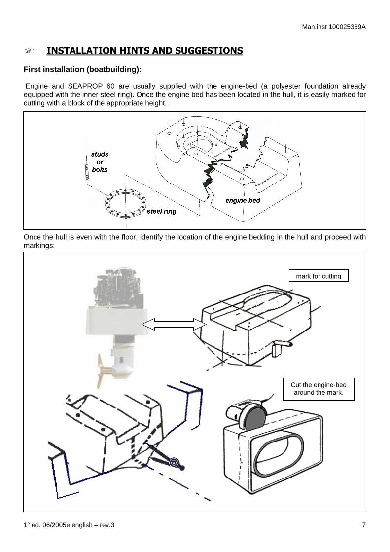
� INSTALLATION HINTS AND SUGGESTIONS First installation (boatbuilding): Engine and SEAPROP 60 are usually supplied with the engine-bed (a polyester foundation already equipped with the inner steel ring). Once the engine bed has been located in the hull, it is easily marked for cutting with a block of the appropriate height.
Once the hull is even with the floor, identify the location of the engine bedding in the hull and proceed with markings:
Cut the engine-bed around the mark.
mark for cutting

Man.inst 100025369A
1° ed. 06/2005e english – rev.3 8
Fixing the engine bed to the hull: Prior to glass definitely the engine bed, the thru-hull hole has to be marked for cutting. This SEAPROP leg will pass into the water via the circular opening (hole) . Fit the engine bed in its location and mark the thru-hull opening: Once marked, remove the engine bed and cut

Man.inst 100025369A
1° ed. 06/2005e english – rev.3 9
The Engine bed is glassed to the hull both around the outside of the bed, and around the hole cut in the hull for the drive leg, as shown in this diagram. Photo's of the process follow.
Engine-bed located in the hull, outside glassed to hull.

Man.inst 100025369A
1° ed. 06/2005e english – rev.3 10
Perform any adjustment to match the alignment of the engine -SEAPROP 60 package, then tighten all fasteners to the recommended values.
Installation (servicing the SEAPROP): To remove and reinstall SEAPROP 60 repeat the above procedure in reverse order.
Rubber cover installation
To improve hull efficiency a rubber sheet 3 to 5 mm. thick can be fitted; slid it through the SEPROP leg and paste to the hull.
Move the engine towards SEAPROP input housing and connect the flexible input coupling, the housing, engine mounts, checking for proper alignment referred to the bow to transom main axis.
Place the thru-hull flange onto the engine bed so that it matches with the studs or the bolt bores. Crew nuts or bolts but do not tighten. The resilient mounting racket can be fitted, but do not tighten the clamp yet.
Slid down the SEAPROP though
the hole
Move the engine towards SEAPROP

Man.inst 100025369A
1° ed. 06/2005e english – rev.3 11
Next steps:
• Connect the shifting “push&pull” cable o Connect one side of cable to the dashboard control lever (adjust it in neutral position)
• Fill with ATF oil = minimum quantity = 3,0 liters
• Self-foldable propeller installation
1. Connect the opposite side of the cable to the SEAPROP lever (shifted in neutral position)
2. Fit the retaining sleeve on the
cable and fix with the fastener
3. Screw on the cable threaded end 4. Screw head until its hole aligns
with shift lever fixing pin hole
5. Secure nut on head
6. Fit fixing pin on head and add the securing split pin
7. Secure the retaining sleeve on
control cable racket
8. Shift the lever from the dashboard
9. Check and adjust the cable so that the forward and reverse position match with the forward and reverse detent position of the SEAPROP lever.
• Connect the water sensor (“normally opened contact” – 12/24V DC) to an alarm signal (snooze or light bulb) on dashboard
Man.inst 100025369A
1° ed. 06/2005e english – rev.3 12
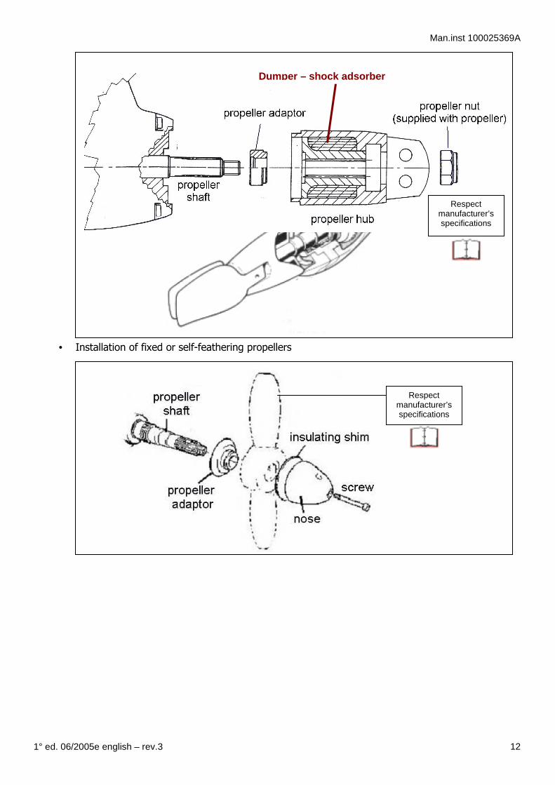
• Installation of fixed or self-feathering propellers
Respect manufacturer’s specifications
Respect manufacturer’s specifications
Dumper – shock adsorber

Man.inst 100025369A
1° ed. 06/2005e english – rev.3 13
Antifouling protection Outboard drives can be generally affected by Galvanic corrosion (is what happens when two dissimilar metals are immersed in an electrolyte, and are electrically connected). The oxide layer, which gives the grey-white colour to aluminium, offers some protection against air temperature, salinity, aeration, and pollution or water corrosion .
Nevertheless, this is not the ultimate protection, for two reasons. First, this layer can be damaged by abrasive actions or scratches that allow moisture to attack and corrode the metal before a new layer of oxide forms. Second, the oxide itself can be corroded by many different seawater salt components. A better and rather complete integrity of the SEAPROP leg can be achieved by painting 2 or more layers of specialized outboard and propeller antifouling paint (in general, no copper, mercury, or lead based anti-fouling paint should be used on metal unless you know that they are compatible or an appropriate type of sealer coat is first applied to the bare metal)
Do not paint the SEAPROP Leg zinc anode and tail (propeller) cone anode
WARNING:WARNING:WARNING:WARNING:
exhausted oil must be disposed in specific waste containers strictly according to local legislation and rules

Man.inst 100025369A
1° ed. 06/2005e english – rev.3 14
� LUBRICATION & OIL INSPECTION
ATF oil First change Other changes/inspections
� filling 50 hours Every 400 hours and/or once a year
(whichever occurs first)
� oil level check weekly weekly
Oil drain Oil can be drain in two different ways. WARNING: oil is harmful and can damage you and the environment
• Perform below operations with engine off and cool oil • Use adequate protections and screens (protection gloves and goggles)
a) boat floating in water, from the engine room This method consists in pressurizing the transmission so that oil is ejected because of the pressure.
b) boat moored Oil can be drain from the drain hole of the lower leg.
1. remove oil dipstick A 2. loosen and remove drain plug B (M10 thread) (save
apart the copper washer) and fit a rubber hose to drive the oil ejected to a reservoir
3. let air in through the oil dipstick hole (max. pressure 0,5 bar = 50 Kpa =7,5 PSI).
4. once oil has been fully drained, remove the rubber hose(s), reinstall the oil dipstick and the oil drain plug with its copper washer
A
B
A
B
1. loosen & remove plug A 2. loosen & remove oil drain plug B 3. to ease oil flow, manually rotate the
propeller shaft

Man.inst 100025369A
1° ed. 06/2005e english – rev.3 15
� MAINTENANCE SCHEDULE
First 50
operating hours weekly
every 400 hours or yearly
Every 2000 hours
Lubrication (ATF oil)
�� replace
� check level & top up
�� replace
�� replace
Control & shifting check and adjust
� check
check and adjust check and adjust
Zinc anode � inspect
� inspect
�� replace
�� replace
Propeller retaining nut
tighten
� inspect tighten
�� replace
Antifouling paint � inspect
� inspect
paint or touch up paint or touch up
Water inlets clean clean clean inlet and
internally clean inlet and
internally
Thru-hull diaphragms
� inspect
� inspect
� inspect
�� replace
Rubber cover � inspect
� inspect
��� inspect and/or
replace
�� replace
INSPECTIONS For those engines where the fresh water circuit uses the SEAPROP leg’s water inlets always inspect, (when boat out of water) that they are free from fouling. In case of cool temperature or preparing the boat for the dead season (winterizing), drain all fresh cooler circuit trough the transmission, by opening thoroughly the water valve. SEAPROP Leg ZINC ANODE replacement
Always replace the zinc anode with all its screws. Once screws have been tightened, tighten again on to two times more: zinc is ductile and screws may not be properly tightened. A poor tightening could affect the proper connection between the zinc anode and the transmission. The zinc anode protects the SEAPROP leg only and is not replaced by the propeller anode, which only protects the propeller.

Man.inst 100025369A
1° ed. 06/2005e english – rev.3 16
WARNING: continuous sailing with SEAPROP in neutral should not exceed 6 to 7 hours , then
switch on the engine and let it run at idle for 15 minutes about, to lube the SAEPROP transmission.
� SPARE PARTS & AFTERMARKET
Always refer to the Boat builder and/or Twin Disc Technodrive Service Network
for more information, please contact:
Twin Disc TECHNODRIVE s.r.l.Twin Disc TECHNODRIVE s.r.l.Twin Disc TECHNODRIVE s.r.l.Twin Disc TECHNODRIVE s.r.l.
Via S.Cristoforo 131Via S.Cristoforo 131Via S.Cristoforo 131Via S.Cristoforo 131
40404040010 S.Matteo Decima (BO) 010 S.Matteo Decima (BO) 010 S.Matteo Decima (BO) 010 S.Matteo Decima (BO) ---- ItalyItalyItalyItaly
Tel. (051) 6819711Tel. (051) 6819711Tel. (051) 6819711Tel. (051) 6819711
Fax 6824234 Fax 6824234 Fax 6824234 Fax 6824234 –––– 6825814682581468258146825814
� OPERATING sailing with engine off: 1- SEAPROP equipped with self-foldable propellers
• Shift the SEAPROP lever in reverse: the transmission stays still in reverse , propeller’s blades fold, no resistance is opposed while sailing.
2- SEAPROP equipped with non foldable propellers, self feathering propellers
• Shift the SEAPROP lever in reverse, the propeller does not rotate, but resistance is opposed while sailing.
• Shift the SEAPROP lever in neutral, the propeller rotates, therefore a smaller resistance is opposed while sailing.
Man.inst 100025369A
1° ed. 06/2005e english – rev.3 17
www.technodrive.it
Owner Service Log FOREWORD On receipt of your new boat equipped with SEA PROP 60, the authorised dealer has signed the pre-delivery coupon thus confirming to have carried out a pre-delivery service according to the manufacturers specifications. Future service requirements are indicated in this OWNER SERVICE LOG section. When these services are carried out, the Twin Disc Technodrive Marine dealer will stamp the respective stubs. This servicing will assist in maintaining the value and satisfactory operation of your SEA PROP 60. It lies in the owner's interest that for maintaining warranty and best performance of his SEA PROP 60 he always insists on the sole utilization of Twin Disc Technodrive replacement parts, operational fluids and lubricants as well as Twin Disc Technodrives proved service procedures! It is important that you study this booklet carefully as it will assist you in achieving satisfaction from your SEA PROP 60. Please retain this manual in the boat as it MUST be presented to Twin Disc Technodrive dealer whenever you require WARRANTY SERVICE. IMPORTANT NOTE: This manual contains all service activities required for your sail drive. Checks and maintenance for the other parts of a complete drive system still need to be completed. Any such procedures are to be found in separate, attached booklet(s) of the individual manufacturer's literature provided with the engine and other drive components. Whenever this manual refers to components like Manual Operation, etc., such instructions only apply where applicable since they are not used on every SEA PROP model.

Man.inst 100025369A
1° ed. 06/2005e english – rev.3 18
SeaProp 60 Fault Finding Chart
Symptom Reason Cause Remedy
No Drive ahead or astern Loosened or out of setting control cable Engine-transmission connection Internal failure Propeller missing
Not in gear - No input rotation Loosened coupling fasteners Elastic coupling failed Damaged cone clutch g/box Low oil level Propeller nut loosened or lost
Broken/incorrect cable installation Contact Twin Disc dealer Contact Twin Disc dealer Contact Twin Disc dealer Top up as required (drive vertical) Inspect, tighten or replace
Prop speed does not increase with engine speed ahead or astern
Loosened or out of setting control cable Slipping clutch
Not fully in gear - No input rotation Worn clutch feeder ring Damaged joint face 'O' ring Worn Clutch plates
incorrect cable or control lever setting Contact Twin Disc dealer Use 'O' ring kit and repair Contact Twin Disc dealer
Excessive oil temperature
Internal damage Too much oil Slipping clutch Clutch seized
Over load through hitting foreign bodies Over filled Worn clutch feeder ring Blocked oil way
Contact Twin Disc dealer Fill to correct level See above Contact Twin Disc dealer
Engine & SeaProp Excessive oil temperature
Low efficiency of the Cooling circuit
Engine water cooling valve partially closed Seawater ports partially clogged
Inspect and adjust Inspect and clean
Vibrations Internal damage Propeller foldable blades not fully displayed Damaged propeller blades
Over load through hitting foreign bodies Folding mechanism faulty or dirt Over load through hitting foreign bodies
Inspect and/or Contact Twin Disc dealer Inspect and clean, lube Inspect, repair or replace

Man.inst 100025369A
1° ed. 06/2005e english – rev.3 19

Man.inst 100025369A
1° ed. 06/2005e english – rev.3 20

Man.inst 100025369A
1° ed. 06/2005e english – rev.3 21
ADDITIONAL INFORMATION common rules and practice
1. Removal of complete SEAPROP from boat. Note: Boat must be removed from water. Failure to do so will allow water to flood
boat and cause damage. Some installations, however, may not provide enough deck clearance to remove entire Sea Prop. In such cases, remove powerhead and lower unit separately.
1. Remove boat from water. 2. Remove propeller. 3. Disconnect water line from the water inlet valve to engine compartment. 4. Disconnect throttle and shift cables at engine and adapter housing. 5. Store locking type fasteners so they won't get lost or substituted. 5. Remove screws from around mounting plate. 6. Lift SEAPROP up, then tilt powerhead aft to pass gearcase thru mounting fixture. Complete Sea Prop can now be removed from boat. 2. Installation of complete SEAPROP 1. Reinstall Sea Prop by reversing the removal procedure. 2. Install a new rubber gasket around mounting plate. Do not use any sealer. 3. Follow a criss-cross pattern and torque the mounting plate bolts to 15-20 ft. lbs. (20 – 27 Nm) 4. Check for leaks. 5. Re-attach the shift and throttle cables using the locking type connectors provided. Do not substitute these fasteners. Improper substitution of fasteners may result in control cables coming loose. Operator may lose control of boat. FASTENERS Use specific fasteners for marine application:
• Never use Zinc plated fasteners: these will rust quite quickly because the protective plating is not very thick compared to a hot-dipped zinc coating.
• fasteners or fittings that are exposed to water are not made of brass, naval bronze, or manganese bronze
CORROSION PROTECTION & PREVENTION
• no copper alloys (brass, bronze, etc.) within 60 cm (2') of aluminium outdrive (Copper and copper alloys such as brass and bronze must not be joined to aluminium that is exposed to the weather because of the vigorous galvanic corrosion that they can cause. Stainless steel is much more noble (further from zinc) than aluminium but it develops a protective oxide coating so corrosion of the aluminium is minimal. Also, the corrosive effects of a small stainless fastener are spread out over a relatively large area of the aluminium fitting and so it will do little concentrated damage)

Man.inst 100025369A
1° ed. 06/2005e english – rev.3 22
• if propeller, prop shaft, or rudder shaft are stainless steel, waterproof grease or thread sealant has to be used to keep salt water out of threads, shaft taper and key way. Make sure grease is not graphite based.
• Do not use gaskets containing asbestos or graphite and no underwater use of graphite based grease or graphite impregnated packing
• no copper, mercury, or lead based anti-fouling paint on aluminium or mild steel • In general, no metal based anti-fouling paint should be used on metal unless you know that
they are compatible or an appropriate type of sealer coat is first applied to the bare metal. � Modern self-abating anti fouls will not last very long if the boat is used under power for
extended periods of time. � Do not paint the tail cone anode !
• Zinc corrosion protection system � New zincs should always be bright, unpainted and not corroded away
(There may be zincs in the engine block, in heat exchangers, on the rudder, or on outdrives)
� zinc connection should be locked with star washer and moisture sealed
The SEAPROP Leg zinc anode protects the saildrive leg only and is not replaced
by the propeller anode, which only protects the propeller. NOTE: It is important that the propeller should be well filled with grease. This will prevent marine growth inside the propeller and the formation of stagnant water that can promote corrosion. Any light multi-purpose, lithium based grease, particularly if labelled as suitable for marine use, is suitable for use in your SEAPROP output shaft, before installing the propeller. Extreme pressure grease can be used but is not required. A few sample alternatives are: � Valvoline Val Plex M grease � CRC #SL-3110-New Generation � Mobil Mobilgrease XHP � Castrol LMX � Spheerol AP or LMM � Total Lubmarine EPEXZ, SKF LGWA 2.0/4

Man.inst 100025369A
1° ed. 06/2005e english – rev.3 23