user’s manual ://static1.squarespace.com/static/5926e4abd482e9754a4eb348/t/... · with our...
TRANSCRIPT

BlueLink Diagnostic Solutions CAN Analyzer, 722.9 VGSNAG, OBD II
Remoter & Launcher
USER’S MANUAL
http://www.BlueLinkDiag.com

Table of Contents
A. Overview................................................................................1
B. Support..................................................................................1
C. Requirements..........................................................................2
D. Installation:
1. BlueLink Software...............................................................2
2. Launcher Use.....................................................................3
3. Mongoose..........................................................................4
E. Remote Coding:
1. Setup................................................................................5
2. Use...................................................................................6
F. Local Diagnostics Overview.......................................................7
G. VGSNAG Tool:
1. Overview...........................................................................8
2. Connectivity....................................................................8-9
3. Software.....................................................................10-21
H. CAN Analyzer:
1. Overview.....................................................................22-23
2. Connectivity................................................................24-25
3. Software.....................................................................26-29
I. OBD II:
1. Overview.........................................................................30
2. Connectivity.....................................................................31
3. Software.....................................................................32-37
Quick Reference – Navigation Tree.....................................Back Cover

A: Overview
Welcome to BlueLink Diagnostic Solutions! Thank you for choosing to purchase
our product. You now own a solution that is more than just a factory tool. It is a
gateway to utilizing a number of data-driven services.
The BlueLink solution represents a “new” way forward in automotive diagnostic
testing. It is an end-to-end tool that delivers solutions to the technician rather than
just access to third party information. Our full system (with a monthly subscription) leverages seamless integration of the Internet and access to expert
technician support and streamed online diagnostics to focus on restoring maximum
efficiency in the service bay.
B: Support
Online Live! Support:
See our BlueLink Launcher Overview on page 3 for information regarding Live
Online Chat, Live Desktop Remote Control or obtaining Remote Programming
Services via our coding queue.
E-mail Support:
Any customer requests or questions can be e-mailed directly to
[email protected]. This will immediately generate a help ticket and send a message to all members of our BlueLink Support Team.
Telephone Support:
Telephone support is usually available during normal hours of operation, Monday
through Friday 9:00am - 5:00pm Eastern Time, at: (919) 226-1377
Page 1

C: Requirements
The recommended configuration is:
- Laptop with 1GHz+ Intel Dual Core (or equivalent)
- Microsoft Windows XP Professional SP3, Vista or Windows 7/8/10
- 500 MB hard drive space
- 1 GB+ internal RAM
- 1280x720 or greater screen resolution - USB 2.0
- Internet connection via IEEE-802.11b+ or RJ-45 Ethernet interface
- Cable or 2nd Gen+ DSL-based service preferred. Cellular Services
can be intermittent, and satellite will not work for remote coding
D.1: Installation – BlueLink Software
1. If your kit came with a physical CD, insert it. Setup will auto start.
2. Click ‘Install’ and setup will automatically start all the installers for you.
Notes: - If your CD was purchased prior to Jan 1, 2010 please simply follow the
all-digital steps below and discard your disc. It is too old to use.
- If installation does not auto run, go to your CD Drive and Double-Click:
“CD_Setup.exe” to run this setup.
- For older machines and machines without the necessary prerequisites,
initial installation can take up to 20 minutes.
3. If your purchase did not come with a physical disc, get the Launcher from
http://www.BlueLinkDiag.com, Under Products> BlueLink Launcher 4. You may need to temporarily disable anti-virus if it seems to not install or
security warnings pop up.
5. Now choose any option and press “OK” to auto-update or install it!
Page 2

D.2: Installation – BlueLink Launcher
The BlueLink Launcher…
Double click on the icon on your desktop to get started. Select what
you’d like to do, and then press “OK” -- that’s it! The Launcher will
install it if it’s missing and update it if needed. Always fast, always
free… always blue.
The first time you run our launcher, enter the Shop Name & Email you used to
make your purchase. This will automatically help us validate your software for use.
…is More than just a unified
starting point!
The Launcher will automatically
update itself and any of the
programs you run from it if a new version is available.
This means you are always
guaranteed to have the newest
application data, best support
experience and the safest remote
coding right at your fingertips.
[Local Diagnostics]: CAN Analyzer, OBDII & 722.9 Tools
This is where you can run the “CAN Analyzer”, “OBD II Program” or the
“VGSNAG/722.9 Tools.” These are for running diagnostics locally on your machine
and do not involve our staff, nor incur any additional charges for their use.
[Team Viewer]: Meetings & Remote Desktop
With our BlueLink Subscription, you’ll have desktop control support from us &
experts who use BlueLink as a means of providing support to their customers (Fees
for their services may apply). Just choose the meeting room in the [BOX] you wish to join, and press “OK”.
[Live Chat]: BlueLink
Select this to initiate a live, online chat with a BlueLink Staff Member. You’ll have a
small form to fill out so we can handle your request.
[Remote Coding]: J2534 Flash
Experts can also send control unit programming and diagnostics over the internet
directly to your vehicle! Through this app you can make requests by entering your
VIN & Production Date. A technician will automatically call you when your position is up in the queue.
[Mongoose Drivers]: PRO ISO2, PRO ISO, ISO/CAN
Before you can plug in and use your Mongoose, select the driver you need to
install. You only need to do this one time to get the device ready for use.
Page 3

D.3: Installation – Mongoose
Install the Appropriate Driver:
Before you start, make sure your Mongoose is UNPLUGGED from the machine.
Open the BlueLink Launcher, and choose one of the drivers at the bottom to install.
(You only need to do this one time per machine).
PRO ISO/CAN2: Ours say, “BlueLink” and have a 12’ cable
PRO ISO/CAN: Blue/Black housing, 6’ cable ISO/CAN: Clear housing, silver 6’ cable (*No support for Windows 8/10+)
For Windows 7, Vista, 8 or 10:
Connect the Mongoose cable to a USB port on your PC. Windows will detect the
Mongoose automatically and install the drivers without prompting you.
For Windows XP Service Pack 3:
1. After connecting the Mongoose the Found New Hardware Wizard will pop-up
automatically. Select “No, not this time” and click next.
2. Next, choose “Install the software automatically.”
*Note: If the box does not pop up
automatically to install the Mongoose:
3. Click the Windows Start Button> Run
4. Type “devmgmt.msc” and press “ENTER”
5. In the screen that opens, look for the
“Mongoose” or an “Unknown Device”
with the yellow question mark (?)
6. Right Click, then “Update Driver…” and
now you can follow the steps above
Page 4

E.1: Remote Coding – Setup
Remote Coding Overview:
From the BlueLink Launcher, choose the 3rd option “Remote Coding” when you
wish to have BlueLink or one of our partners remotely access your vehicle over the
internet for coding, flashing, activation, or diagnostics (Per-use fees will apply).
Device Setup:
When running for the first time, you’ll
be automatically prompted to select
the PassThru Device you wish to use.
You may be using one of our
Mongooses, or any J2534 Compatible
Device. Just highlight the device you
wish to use and close the box.
If you do not see anything in the box,
please refer to the previous page to
install the Mongoose Drivers, then
press “Re-Scan for Devices” when you
have completed installation.
Account Setup:
Next you’ll fill out your shop Email,
Name and Phone Number. Fill out
these fields and then close the box.
The phone number should ideally be
the one that an expert should call to
easily reach the technician who is
performing work on the vehicle.
It is important to use the same Email and Shop Name you used to pay for
the account to make validation
quicker.
At any time, you can press [TAB] on
your keyboard, or just click in a
different field, and the “Status” at the
bottom will refresh, giving you details
on your account.
The purchase buttons for both pieces are conveniently located in the bottom here
should you need quick links to either the software or a subscription.
Page 5

E.2: Remote Coding – Use
6 Green Lights:
Now that you’ve completed the one-time setup, any time you run it from the
BlueLink Launcher (with Mongoose in the PC) you should immediately get
6 Green Lights. You are now ready for coding from us, or any of our partners. If
coding with someone outside of BlueLink, follow their instructions to obtain service.
*Important: If you do NOT have 6 Green Lights, just look in the bottom left corner of the application. The error message will tell you things you can try.
For Obtaining Mercedes SCN Coding from BlueLink:
For codings of Mercedes by BlueLink, fill out the form and press the large
“[> Submit Coding Request <]” button at the bottom. This will place you in our
electronic queue and notify us to give you a call when your position is up.
- Anything you did not fill out correctly will give errors in RED.
- Priority Service: This option can jump a long, busy line or allow for the possibility
of a member of our staff programming your vehicle outside our hours. Submits
without Priority Service are not accepted beyond 4:30PM EST.
- Add More Comments: After a ticket is submitted, add more notes to your case
file here.
- BlueLink Live Chat!: This opens the same Live Chat that is in our Launcher for you to talk with us at BlueLink should you have any concerns.
- Queue Position? Quote?: Press either of these for info on queue size or pricing.
Page 6

F: Local Diagnostics – Overview
For all of the remaining software features, including the CAN Analyzer, VGSNAG
722.9 Tools and OBDII Software, you’ll be using the Diagnostic Client. The
following general rules will apply when using any of these packages:
To use a button, you can either press its hotkey or click it with the mouse:
F5: Unselect All – Unchecks all checkboxes on the current page.
F6: Select All – Checks all checkboxes on the current page.
F7: Print Report – Generates a report to print of the current page.
(If you opted to install CutePDF, when you choose print, select the
“CutePDF Writer” as your printer and select OK. Then type a file name
and provide a location to save the PDF file.)
F8: Application Settings – Press to open the dialog below:
Display Units: Some values can be
displayed in either US or SI.
Auto-Connect Device: Setting this
to True will connect the current
PassThru Device on Startup. False will prompt before doing so.
PassThru Device: Select the device
the application will use. Changing
from one to another will reset the
application to the Introduction page.
Shop Info: Populating these fields
will automatically put them on reports that you print.
Generate Trace: Leave as False. This will enable the Tracing Engine and allow
us to see scripts you run, should you require assistance.
F9: Navigate Back – Returns you to the previous page.
F10: Reset Page – Resets the current page to its initial state.
F11: Execute Test – Executes the test on the current page.
F12: Navigate Forward – Navigate to the next page.
Connect/Reconnect Device: Due to ignition cycling, changing vehicles, or the
nature of 2534 devices, it is necessary sometimes to reset the app. Press this to
close the PassThru Device and reset to the Intro Page.
Page 7
G.1: VGSNAG Tool – Overview
The VGSNAG Tool is a BlueLink Software product designed to put all the common
plate functions and needs of shops at your fingertips. Ordinarily, to access such
features an SDS (DAS / Mercedes Factory Tool) is required, plus a lot of clicking!
With our software, if your vehicle contains a 722.9 VGSNAG System, you can talk
to it immediately! In fact, because of the way we’ve written this database, you can
even operate all functions without even being connected to a car*.
*Note: Requires purchase of our optional plate-direct accessory.
*Note: Flow Data can only be transferred for the following part numbers:
- VGS-NAG2 (A 033 545 6632/6732) – Not valid!
- VGS2-NAG2 (A 033 545 7732) – Valid!
- VGS3-NAG2 (A 003 446 0310) – Valid!
G.2: VGSNAG Tool – Connectivity Bench Mode
If your plate-direct cable came with two female ends (red/black) for
hooking up a power source, it will require external power. Here are
ways to power it, from most-preferred to least-preferred:
- 12V Fixed DC, 5A Stand-Alone Power Supply (2A for plate only)
- Connected to the Vehicle Battery (or +/- posts)
- Directly to a high-quality, proper vehicle battery maintainer
Page 8
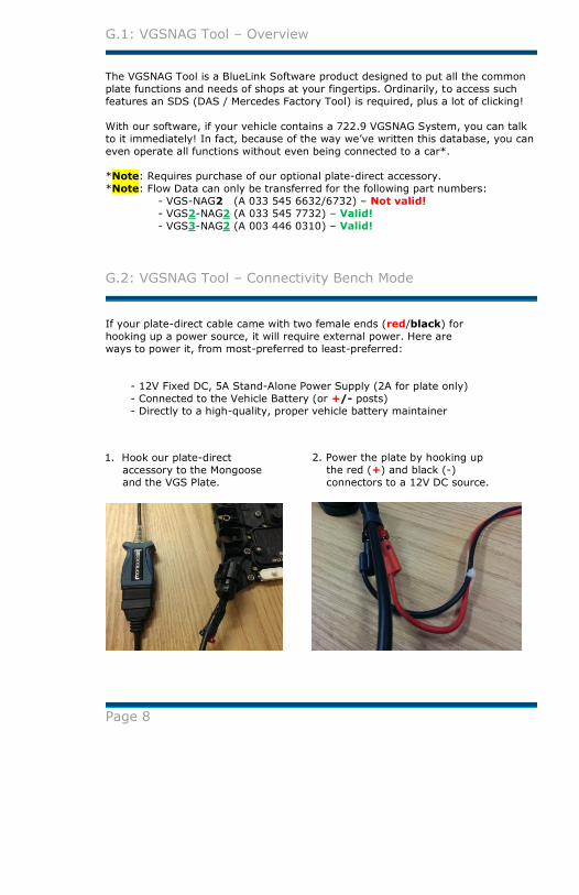
1. Hook our plate-direct
accessory to the Mongoose and the VGS Plate.
2. Power the plate by hooking up
the red (+) and black (-)
connectors to a 12V DC source.

G.2: VGSNAG Tool – Connectivity Vehicle Mode
The vehicle OBDII connector can be in a variety of locations, but is usually visible and accessible without having to manipulate the vehicle. Common locations are:
- Beneath the steering column, centered
- Above the emergency brake
- Above the gas pedal
Page 9
1. If your plate-direct
cable has two OBDII ends,
(M/F), you’ll want to hook
one to the Mongoose, one
to the car, and the round 722.9 connector to the
transmission under the
vehicle.
2. Insert the key in the ignition
and turn it to the “ON”
position to power the vehicle
(starting the vehicle is not necessary).
For either plate-direct cable
configuration, ensure the
Mongoose is connected to the USB
port of your computer.

G.3: VGSNAG Tool – Software
1. First press F8 to open the settings window.
2. Select the “Mongoose ISO/CAN” Device and press OK.
3. Here you can see PassThru Device Status.
4. Once connected, press F12 or ENTER to go to the next screen.
5. Reset the Application and Device at any time.
Ex: Changing Cars, Accidental Unplugging, etc.
Page 10

G.3: VGSNAG Tool – Software
6. Select the database with which to work (“VGSNAG_Transmissions”). To go
to the next screen you can: Double-click on the row, press F12 or ENTER.
7. To go to the previous screen at any time, press F9 or BACKSPACE.
(Just like a web browser).
8. Select the “VGSNAG Vehicle” and go to the next screen. 9. Wait while a connection is made to the vehicle. The next screen will load when
completed.
Page 11

G.3: VGSNAG Tool – Software
10. Next, you will see a list of selectable items for your 722.9 ECU. In this
next example, we select ”Real Time Actual Values” for a listing of Actual
Values.
11. If you would like to view Actual Values by group, like “Factory Flow Data”,
“Speeds”, or “VIN”, make sure the default “Actual Value Groups” is selected
before proceeding. The Actual Value group “Factory Flow Data” is checked
by default. Check “Speeds” and/or “VIN” if you want to view these blocks
of Actual Values as well. Then press F12 or ENTER.
12. If you would like to select individual Actual Values, including Actual Values
included in the Actual Value Groups in Step 11, choose “List Mode”. Then
press F12 or ENTER.
Page 12
G.3: VGSNAG Tool – Software
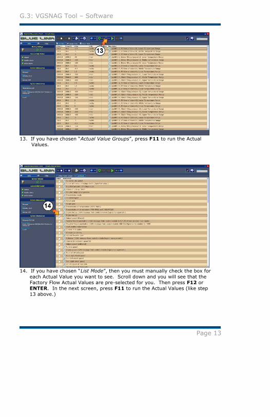
13. If you have chosen “Actual Value Groups”, press F11 to run the Actual
Values.
14. If you have chosen “List Mode”, then you must manually check the box for
each Actual Value you want to see. Scroll down and you will see that the
Factory Flow Actual Values are pre-selected for you. Then press F12 or
ENTER. In the next screen, press F11 to run the Actual Values (like step
13 above.)
Page 13

G.3: VGSNAG Tool – Software
15. Choose “Read and Clear Fault Codes” to proceed with fault code data.
Then press F12 or ENTER.
16. The check box for “Read Faults” will be pre-selected upon entering this
screen. Press F11 to continue. 17. To Clear Faults, select the check box for “Clear Faults”. Press F11 to
continue.
Page 14

G.3: VGSNAG Tool – Software
18. If you have chosen to “Clear Faults” per Step 17, then a Green Circle will
appear to the left of the check box if “Clear Faults” was successful.
However, a Red Circle will appear if “Clear Faults” was not successful.
19. If you have chosen to “Read Faults” per Step 16, Fault Codes are listed.
To view Freeze Frames associated with each Fault Code, Left Click the box
under the column FF and to the left of your chosen Fault Code.
Page 15

G.3: VGSNAG Tool – Software
Next is a list of Freeze Frames associated with this Fault Code with a check mark
pre-selected for each Freeze Frame. You may remove any value you do not wish
to view, then Press F12 or ENTER.
20. Press F11 to read the Freeze Frame data.
Page 16

G.3: VGSNAG Tool – Software
21. Choose “Complete List of Fault Codes” to view all possible fault codes for a
VGSNAG control unit. Then press F12 or ENTER.
22. A complete list of fault codes. Scroll up or down to view all fault codes.
This screen is simply for your viewing.
Page 17

G.3: VGSNAG Tool – Software
23. Choose “ECU Version information” to view this information. Then press
F12 or ENTER.
24. Press F11 to read the ECU Version Information.
Page 18

G.3: VGSNAG Tool – Software
25. Choose “Read and Transfer Factory Flow Data” to start this task. Then
press F12 or ENTER.
26. Press F11 to read the old plate data.
*Note: Make sure that the old plate is connected at this point is a
“VGS2-NAG2” plate!
A “VGS-NAG2” plate (note the lack of the first “2”) is NOT ACCEPTABLE!
Page 19

G.3: VGSNAG Tool – Software
27. A pop-up screen appears reminding you to ensure the correct
“VGS2-NAG2” plate is connected. Press “OK” when this has been done.
28. Once the data has been read from the old “VGS2-NAG2” plate, the
following pop-up appears. Follow the directions in this pop-up.
Turn off the ignition, disconnect the wiring harness from the old
“VGS2-NAG2” plate, and then connect the wiring harness to the new
plate.
Turn the ignition on to key position two (2), so that all of the dashboard
lights are turned on. Then, press the “OK” button. Writing to the new unit will begin.
Page 20

G.3: VGSNAG Tool – Software
29. If the write has been successful, you will see the following pop-up.
If the write has been unsuccessful, go back to step 25 and repeat.
Ensure all connections to the wiring harness, etc., are secure.
Page 21

H.1: CAN Analyzer – Overview
Background:
In Mercedes-based vehicles there is a common bus known as “Body CAN”, which
several control units are connected to. Some units may continue to perform their
normal functions, but also cause a continuous current draw when the ignition is
off. This is known as a “Failure to Sleep.”
Vehicle Support:
Our solution can help identify these units which have failed to go to sleep. We
support the following CAN-B Vehicles with Bus-Wake Technology.
*Note: And a subset of commands for (*) vehicles with non-Bus-Wake
- 164/169/171/199/202*/203/204/208*/209/210*/211/
215/216/219/220/221/230/240/245/251/461/463
Proper CAN-B Vehicle Voltage:
For the CAN Analyzer to function, your car’s CAN-B Network must be operational
and at the correct voltages. Our product works just like a control unit and will
need to observe normal operations to make interpretations. If the CAN Analyzer
can’t make a connection with your vehicle, use this chart to verify your voltages. You can use our Red/Black x30 Break-Out Cable – test each side to vehicle ground.
Chassis High Low High Low
202, 208, 210 1.80 3.20 0.10 4.90
All Others 0.65 4.65 0.03 11.00
Interior CAN B VoltageActive Sleep
Active / Sleep: The vehicle state. With key ON, it should be active.
High / Low: The red or black connector’s voltage to vehicle ground
(Which one is which will vary based on vehicle).
Page 22

H.1: CAN Analyzer – Overview
Diagnostic Procedure:
If a customer’s vehicle exhibits a battery drain (CAN stays awake) and the vehicle
has been diagnosed with a scan tool and no faults or issues were found, then it is
time to use the CAN Analyzer. The Connectivity Guide (p24-p25), and use the
Software Guide (p26-p29) contain all the details, but here is the usage overview:
Step 1: Preparation for Diagnosis: - Disconnect all other diagnostic equipment & battery maintainers - Close all doors and run the cable thru a lowered window to your laptop
- Remove key from ignition
Step 2: Begin diagnosis with the “Bus Status”:
A simple test to tell you if the bus is Active (Awake) or Passive (Asleep).
Make sure the vehicle has sat undisturbed for 2 – 5 minutes before running and each time you unplug a unit. - If Active (Awake) proceed to the Step 3
- If Passive (Asleep) proceed to Step 5
Step 3: Continuing diagnosis with the “Normal Test”:
This test will identify units that exhibit behavior we identify as bad - If a unit is found, unplug the module(s) mentioned in the row and go back to Step 2, to make sure there are no other bad units
- If all communications appear normal, proceed to Step 4
Step 4: Continuing diagnosis with “Not Ready to Sleep”:
This test will simply show a view of the units currently communicating on the
car. They are not bad, but simply sending commands. - If it is a single unit listed, try unplugging it and go back to Step 2
- If many rows of units are listed, double check Step 1, or you may have an
issue with Central Gateways, EIS, or SAMs (through which many units run)
Step 5: “Monitors” (First-Found & every 5-Minutes):
From time to time, you may work on vehicles that exhibit a battery drain periodically. In these cases, you can monitor the vehicle while you are away.
It is also a great idea to run after you have found a bad unit to make sure there
are no other issues. These tests will run indefinitely unless a unit wakes up. - If the test has run for 30+ minutes without stopping, you’re done!
- If the test stopped and it is showing a unit, this is the first unit that first
spoke on the Body CAN Bus. Unplug it and return to Step 2
It keeps saying the vehicle is asleep, but I have a draw! Your CAN-B Network is OK! Begin to check other things in the vehicle. Start with the fuse box.
Are units shown in Step 4 bad? Removing it made the problem go away. Check the inputs to that unit before you go and order a new one. We’ve seen bad trunk lid
buttons keeping the PSE pump active, stuck CDs keep the Audio System active, and bad key FOBs & temp sensors wake the cluster. Check your wiring diagrams & think about inputs.
The units in Step 2 keep changing each time I run it! If you clearly see one unit more than others each time you run it, try unplugging that one first. If
it truly seems random it may be a moisture problem, or issues with the Central Gateway/EIS.
What is the RCM (Rear Control Module)? This module is usually near the Rear SAM, but it is its own module.
Page 23

H.2: CAN Analyzer – Connectivity
1. Locate the Body CAN harness in the vehicle and connect the Mercedes X30
Body CAN cable (female connector) into any of the open connectors. The
pins will only orient in one direction.
Consult Star Finder and/or Web ETM for specific directions on finding your
X30 Body CAN connector.
2. Connect the Mercedes X30 Body CAN cable to the BlueLink converter cable.
Orientation will differ based on the vehicle you are connecting to.
*Note: When you select the vehicle to connect to, the application will let
you know if it thinks your connectors are reversed.
Page 24
Photo Example:
Vehicle: S430
Location: Under the steering column
Connections: Green / White Cables Red -> Green, Black -> Orange
This shows the standard
orientation. Your vehicle
may be reversed.*
Photo Example:
Vehicle: E320
Location: Passenger Door Sill
Connections: Brown / Red Cables
Red -> Orange, Black -> Green

H.2: CAN Analyzer – Connectivity
Page 25
3.a *If you received our newer cable
with M/F OBDII ends (as in photo),
plug the other end into the OBDII
port of the vehicle for power &
ground.
3.b *If you have our first-generation
adapter cable with a stand-alone
ground wire, ground the connection
by attaching to a grounded portion
of the vehicle, such as a seat rail.
4. Remove the key from the
ignition and close all doors.
*Important: Do not connect a
battery maintainer when analyzing!
(You will need to wait 1-5 minutes
minimum for the vehicle to
attempt to sleep).
5. Lastly, attach the Mongoose to
the adapter cable and ensure the
other end is connected to the USB port of your computer.

H.3: CAN Analyzer – Software
1. First press F8 to open the settings window.
2. Select the “Mongoose ISO/CAN” Device and press OK.
3. Here you can see PassThru Device Status.
4. Once connected, press F12 or ENTER to go to the next screen.
5. Reset the Application and Device at any time.
Ex: Changing Cars, Accidental Unplugging, etc.
(*Note: When using CAN Analyzer, the battery voltage may read 0.0,
if you have our 1st-Gen cable that does not connect to the OBD II port.)
Page 26

H.3: CAN Analyzer – Software
6. Select the database with which to work (“CAN_Analyzer”). To go to the
next screen you can: Double-click on the row, press F12 or ENTER.
7. To go to the previous screen at any time, press F9 or BACKSPACE.
(Just like a web browser).
8. Select the Vehicle with which to work and go to the next screen. (Here, we are choosing the “E-Class - 211”)
Page 27

H.3: CAN Analyzer – Software
9. Wait while a connection is made with the vehicle.
It is IMPORTANT to wait for the vehicle to attempt to sleep after connecting
before executing any tests. Ensure that you have not opened any doors, or cycled
the ignition for 1 - 5 minutes to guarantee all control units should currently be
asleep.
10. Select ”Complete List of CAN IDs” for a listing of all CAN IDs on the chassis
11. Select ”All Tests & Monitors” to test the vehicle.
Page 28

H.3: CAN Analyzer – Software
12. Select the type of test to execute.
13. Start the test by pressing F11. Stop the test by pressing F11 again.
If there are bad or awake control units on the vehicle, they will appear beneath the
test you ran. Otherwise, an empty list and a green check mean none were found.
*Important: Some CAN-IDs map to more than one possible unit. Units in the
same row separated by semi-colons (;) mean either/or. Not both! You can usually
rule some out based on body-style or features.
Refer to CAN Analyzer – Overview (p23) for testing details and FAQ.
Bus Status: A simple test to tell you if the CAN Bus is awake or asleep.
Normal Test: A test that detects only faulty control unit behaviors that wake the
CAN Bus. We test for documented pattern failures for control units we have
received in house, from shops just like yours!
Not Ready To Sleep: Units that appear here are simply normally reporting by
Mercedes spec, that they are still not ready to sleep. This means they are not
necessarily “bad”, but related to the problem.
Monitors (Stop on First Found / Keep Logging): Use this test for a vehicle that is currently asleep, but suspiciously draws the battery while you are away
from the vehicle (overnight, or while out to lunch). One will stop running
automatically if it finds any offender, where the other will keep logging units that
wake the car up to every 5 minutes.
Page 29

I.1: OBD II – Overview
Background
OBD II is the prevailing standardization intended for computer-based emissions
testing. The OBD II specification provides for a standardized hardware interface,
the female 16-pin J1962 connector (shown below). This standard applies to all
vehicles that are 1996 and newer.
OBD II Connector
Supported Protocols In this product release, with Drew Technologies ISO/CAN Mongoose the following
vehicle protocols are supported:
European and Asian
- ISO-9141
- ISO-14230
Various
- ISO-15765 CAN
With other 2534 devices we also support:
Ford and GM
- J1850 PWM
- J1850 VPW
BlueLink Implementation of OBD II
The BlueLink OBD II database service is designed to support all of the OBD II
modes. The data service dynamically filters all information presented to the user
based upon the abilities of the vehicle and attached 2534 device.
The BlueLink OBD II data service offers a complete link between the technician and
OBD II. With support for all OBD II modes, the technician can easily:
- Utilize any OBD II supported mode without limitations - Actively monitor an Actual Value while manipulating the vehicle
- Compare user-defined Actual Value combinations for monitoring;
via Graphs and Gauges
- Conveniently obtain additional information and help regarding a fault
Page 30

I.2: OBD II – Connectivity
This connector can be in a variety of locations, but is usually visible and accessible without having to manipulate the vehicle. Common locations are:
- Beneath the steering column, centered
- Above the emergency brake
- Above the gas pedal
Page 31
1. Locate the OBD II connector
in the vehicle and connect
the Mongoose.
2. Insert the key in the ignition
and turn it to the “ON”
position to power the vehicle
(starting the vehicle is not necessary).
3. Lastly, ensure the Mongoose is
connected to the USB port of
your computer.

I.3: OBD II – Software
1. First press F8 to open the settings window.
2. Select the “Mongoose ISO/CAN” Device and press OK.
3. Here you can see PassThru Device Status, and if connected to a car, its
battery voltage.
4. Once connected, press F12 or ENTER to go to the next screen.
5. Reset the Application and Device at any time.
Ex: Changing Cars, Accidental Unplugging, etc.
Page 32

I.3: OBD II – Software
6. Select the database with which to work (“OBD_II”). To go to the next
screen you can: Double-click on the row, press F12 or ENTER.
7. Return to the previous screen at any time by pressing F9 or BACKSPACE.
8. Here, select the protocol type of the vehicle that is being diagnosed. If you
are unsure, let us “Auto Detect” it for you, as shown above.
Through our dynamic filtering process, we only list protocols supported by
the PassThru Device you are using.
Page 33

I.3: OBD II – Software
9. Wait while a connection is made with the vehicle and its supported features
are detected.
10. On the “Operation Selection” screen, a list of available operations specifically filtered for your particular vehicle are available for you to use.
Page 34

I.3: OBD II – Software
Selecting the “Current Powertrain Diagnostic Data” from the Operations screen
allows you to determine real-time actual values from your vehicle.
11. Select a single group to test (as shown), or select them all. Then press
F12 to proceed.
12. Pressing F11 begins the test. The values will continually be retrieved
from the vehicle until you stop the test.
Try either the Gauge View or Graph View to look at the data in a different way!
Page 35

I.3: OBD II – Software
Selecting “Trouble Codes and Powertrain Freeze Frame Data” from the
Operations screen brings us here.
13. Select the type of test to execute, then use F11 to run it.
14. Click here to retrieve Freeze Frame data that occurred for this fault.
15. Click here to retrieve more information from the Search Engine.
Selecting “More” from the “Trouble Codes and Powertrain Freeze Frame Data”
screen displays available search options for the fault.
Examine one by Double-clicking on the row, or pressing F11.
Page 36

I.3: OBD II – Software
For all remaining modes, “Mode 5, Mode 6 and Mode 9”, run their tests by first
pressing F11.
16. Then you can examine additional results via expanding the row, by
clicking on its respective “+” plus sign.
Selecting “Complete Diagnostic Trouble Code Listing” from the “Operation
Selection” screen will display a list of all possible codes OBD II supports.
Page 37

Quick Reference - Navigation Tree