user's guide for the ncep unified post processor (upp ... · ncep unified post processor (upp)...
TRANSCRIPT
UPP V3: User’s Guide
User's Guide for the NCEP Unified Post Processor (UPP)
Version 3
UPP V3: User’s Guide 2
Table of Contents
NCEP Unified Post Processor (UPP) • UPP Introduction • UPP Required Software • Obtaining the UPP Code • UPP Directory Structure • Installing the UPP Code • UPP Functionalities • Setting up the WRF model to interface with UPP • UPP Control File Overview
o Controlling which variables unipost outputs o Controlling which levels unipost outputs
• Running UPP o Overview of the scripts to run UPP
• Visualization with UPP o GEMPAK o GrADS
• Fields Produced by unipost
Acknowledgments: The adaptation of the original WRF Post Processor package and User’s Guide (by Mike Baldwin of NSSL/CIMMS and Hui-Ya Chuang of NCEP/EMC) was done by Lígia Bernardet (NOAA/ESRL/DTC) in collaboration with Dusan Jovic (NCEP/EMC), Robert Rozumalski (COMET), Wesley Ebisuzaki (NWS/HQTR), and Louisa Nance (NCAR/RAL/DTC). Upgrades to WRF Post Processor versions 2.2 and higher were performed by Hui-Ya Chuang, Dusan Jovic and Mathew Pyle (NCEP/EMC). Transitioning of the documentation from the WRF Post Processor to the Unified Post Processor was performed by Nicole McKee (NCEP/EMC), Hui-ya Chuang (NCEP/EMC), and Jamie Wolff (NCAR/RAL/DTC). Implementation of the Community Unified Post Processor was performed by Tricia Slovacek and Kate Fossell (NCAR/RAL/DTC).

UPP V3: User’s Guide 3
NCEP Unified Post Processor (UPP) UPP Introduction The NCEP Unified Post Processor has replaced the WRF Post Processor (WPP). The UPP software package is based on WPP but has enhanced capabilities to post-process output from a variety of NWP models, including WRF-NMM, WRF-ARW, Non-hydrostatic Multi-scale Model on the B grid (NMMB), Global Forecast System (GFS), and Climate Forecast System (CFS). At this time, community user support is provided for the WRF-based systems and NMMB. In addition to the option to output fields on the model’s native vertical levels, UPP interpolates output from the model’s native grids to National Weather Service (NWS) standard levels (pressure, height, etc.) and standard output grids (AWIPS, Lambert Conformal, polar-stereographic, etc.) in NWS and World Meteorological Organization (WMO) GRIB format. UPP incorporates the Joint Center for Satellite Data Assimilation (JCSDA) Community Radiative Transfer Model (CRTM) to compute model derived brightness temperature (TB) for various instruments and channels. This additional feature enables the generation of a number of simulated satellite products including GOES and AMSRE products for WRF-NMM, Hurricane WRF (HWRF), WRF-ARW and GFS. For CRTM documentation, refer to http://www.dtcenter.org/upp/users/docs/user_guide/crtm_ug/CRTM_User_Guide.pdf. UPP Software Requirements The Community Unified Post Processor requires the same Fortran and C compilers used to build the WRF model. In addition, the netCDF library, the JasPer library, the PNG library, Zlib, and the WRF I/O API libraries, which are included in the WRF model tar file, are also required. UPP uses WRF I/O libraries for data processing of all models and as a result UPP is dependent on a WRF build. The JasPer library, PNG library, and Zlib are new requirements with the release of UPPv2.0 and higher, due to the addition GRIB2 capabilities. NCEP provides these necessary codes for download: http://www.nco.ncep.noaa.gov/pmb/codes/GRIB2/ The UPP has some sample visualization scripts included to create graphics using either GrADS (http://cola.gmu.edu/grads/gadoc/gadoc.php) or GEMPAK (http://www.unidata.ucar.edu/software/gempak/index.html). These are not part of the UPP installation and need to be installed separately if one would like to use either plotting package. UPP has been tested on LINUX platforms (with PGI, Intel and GFORTRAN compilers).
UPP V3: User’s Guide 4
Obtaining the UPP Code The UPP package can be downloaded from: http://www.dtcenter.org/upp/users/downloads/index.php ** Note: Always obtain the latest version of the code if you are not trying to continue a pre-existing project. Once the tar file is obtained, gunzip and untar the file.
tar –zxvf UPPV3.2.tar.gz This command will create a directory called UPPV3.2. UPP Directory Structure Under the main directory of UPPV3.2 reside seven subdirectories (* indicates directories that are created after the configuration step):
arch: Machine dependent configuration build scripts used to construct configure.upp bin*: Location of executables after compilation. scripts: contains sample running scripts to process wrfout and nmmb_hist files.
run_unipost: run unipost, ndate and copygb. run_unipost andgempak: run unipost, ndate, copygb, and GEMPAK to plot various fields. run_unipost andgrads: run unipost, ndate, copygb, and GrADS to plot various fields. run_unipost _frames: run unipost, ndate and copygb on a single wrfout file containing multiple forecast times. run_unipost _gracet: run unipost, ndate and copygb on wrfout files with non-zero minutes/seconds. run_unipost _minute: run unipost, ndate and copygb for sub-hourly wrfout files. run_unipostandgrads_global: run unipost, ndate and copygb and GrADS for global wrfout files; results in single GRIB1 file. (WRF data only)
include*: Source include modules built/used during compilation of UPP
lib*: Archived libraries built/used by UPP
parm: Contains the parameter files, which can be modified by the user to control

UPP V3: User’s Guide 5
how the post processing is performed. src: Contains source codes for:
copygb: Source code for copygb ndate: Source code for ndate unipost: Source code for unipost lib: Contains source code subdirectories for the UPP libraries
bacio: Binary I/O library crtm2: Community Radiative Transfer Model library g2: GRIB2 support library g2tmpl: GRIB2 table support library gfsio: GFS I/O routines ip: General interpolation library (see lib/ip/iplib.doc) nemsio: NEMS I/O routines sfcio: API for performing I/O on the surface restart file of the global
spectral model sigio: API for performing I/O on the sigma restart file of the global
spectral model sp: Spectral transform library (see lib/sp/splib.doc) w3emc: Library for coding and decoding data in GRIB1 format w3nco: Library for coding and decoding data in GRIB1 format wrfmpi_stubs: Contains some C and FORTRAN codes to generate
libmpi.a library used to replace MPI calls for serial compilation. xml: XML support – GRIB2 parameter file
Installing the UPP Code UPP uses a build mechanism similar to that used by the WRF model. There are two environment variables that must be set before beginning the installation: a variable to define the path to a similarly compiled version of WRF and a variable to a compatible version of netCDF. The UPP code makes use of the i/o routines in WRF, therefore making it necessary to build WRF code even if processing NMMB forecast data. If the environment variable WRF_DIR is set by (for example), setenv WRF_DIR /home/user/WRFV3 this path will be used to reference WRF libraries and modules. Otherwise, the path
../WRFV3 will be used. In the case neither method is set, the configure script will automatically prompt you for a pathname. To reference the netCDF libraries, the configure script checks for an environment variable (NETCDF) first, then the system default (/user/local/netcdf), and then a user
UPP V3: User’s Guide 6
supplied link (./netcdf_links). If none of these resolve a path, the user will be prompted by the configure script to supply a path. Type configure, and provide the required info. For example:
./configure
You will be given a list of choices for your computer. Choices for LINUX operating systems are as follows: 1. Linux x86_64, PGI compiler (serial) 2. Linux x86_64, PGI compiler (dmpar) 3. Linux x86_64, Intel compiler (serial) 4. Linux x86_64, Intel compiler (dmpar) 5. Linux x86_64, Intel compiler, SGI MPT (serial) 6. Linux x86_64, Intel compiler, SGI MPT (dmpar) 7. Linux x86_64, gfortran compiler (serial) 8. Linux x86_64, gfortran compiler (dmpar) Note: If UPP is compiled with distributed memory, it must be linked to a dmpar compilation of WRF. Choose one of the configure options listed. Check the configure.upp file created and edit for compile options/paths, if necessary. For debug flag settings, the configure script can be run with a –d switch or flag. To compile UPP, enter the following command:
./compile >& compile_upp.log & When compiling with distributed memory (serial) this command should create 13 (14) UPP libraries in UPPV3.2/lib/ (libbacio.a, libCRTM.a, libg2.a, libg2tmpl.a, libgfsio.a, libip.a, (libmpi.a), libnemsio.a, ibsfcio.a, libsigio.a, libsp.a, libw3emc.a, libw3nco.a, libxmlparse.a) and three UPP executables in bin/ (unipost.exe, ndate.exe, and copygb.exe). To remove all built files, as well as the configure.upp, type:
./clean
This action is recommended if a mistake is made during the installation process or a change is made to the configuration or build environment. There is also a clean –a option which will revert back to a pre-install configuration.
UPP V3: User’s Guide 7
UPP Functionalities The UPP,
• is compatible with WRF v3.3 and higher. • can be used to post-process WRF-ARW, WRF-NMM, NMMB, GFS, and CFS
forecasts (community support provided for WRF-based and NMMB forecasts). • can ingest WRF history files (wrfout*) in netCDF format. • can ingest NMMB history files (nmmb_hist*) in binary.
The UPP is divided into two parts:
1. Unipost • Interpolates the forecasts from the model’s native vertical coordinate to NWS standard output levels (e.g., pressure, height) and computes mean sea level pressure. If the requested parameter is on a model’s native level, then no vertical interpolation is performed. • Computes diagnostic output quantities (e.g., convective available potential energy, helicity, relative humidity). A full list of fields that can be generated by unipost is shown in Table 1. • Outputs the results in NWS and WMO standard GRIB1 format (for GRIB documentation, see http://www.nco.ncep.noaa.gov/pmb/docs/). • Destaggers the WRF-ARW forecasts from a C-grid to an A-grid. • Outputs two navigation files, copygb_nav.txt (for WRF-NMM output only) and copygb_hwrf.txt (for WRF-ARW and WRF-NMM). These files can be used as input for copygb. Ø copygb_nav.txt: This file contains the GRID GDS of a Lambert Conformal
Grid similar in domain and grid spacing to the one used to run the WRF-NMM. The Lambert Conformal map projection works well for mid-latitudes.
Ø copygb_hwrf.txt: This file contains the GRID GDS of a Latitude-Longitude Grid similar in domain and grid spacing to the one used to run the WRF model. The latitude-longitude grid works well for tropics.
• Except for new capabilities of post processing GFS/CFS and additions of many new variables, UPP uses the same algorithms to derive most existing variables as were used in WPP. The only three exceptions/changes from the WPP are: Ø Computes RH w.r.t. ice for GFS, but w.r.t. water for all other supported
models. WPP computed RH w.r.t. water only. Ø The height and wind speed at the maximum wind level is computed by
assuming the wind speed varies quadratically in height in the location of the maximum wind level. The WPP defined maximum wind level at the level with the maximum wind speed among all model levels. The static tropopause level is obtained by finding the lowest level that has a temperature lapse rate of less than 2 K/km over a 2 km depth above it. The WPP defined the tropopause by finding the lowest level that has a mean
UPP V3: User’s Guide 8
temperature lapse rate of 2 K/km over three model layers.
2. Copygb • Destaggers the WRF-NMM forecasts from the staggered native E-grid to a
regular non-staggered grid. (Since unipost destaggers WRF-ARW output from a C-grid to an A-grid, WRF-ARW data can be displayed directly without going through copygb.)
• Destaggers the NMMB forecasts from the staggered native B-grid to a regular non-staggered grid.
• Interpolates the forecasts horizontally from their native grid to a standard AWIPS or user-defined grid (for information on AWIPS grids, see http://www.nco.ncep.noaa.gov/pmb/docs/on388/tableb.html).
• Outputs the results in NWS and WMO standard GRIB1 format (for GRIB documentation, see http://www.nco.ncep.noaa.gov/pmb/docs/).
Note: Copygb only works with GRIB1 format; for GRIB2, use wgrib2. (for downloading the source code and information on compiling on your system, see http://www.cpc.ncep.noaa.gov/products/wesley/wgrib2/)
In addition to unipost and copygb, a utility called ndate is distributed with the UPP tarfile. This utility is used to format the dates of the forecasts to be posted for ingestion by the codes. Setting up the WRF or NMMB model to interface with UPP The unipost program is currently set up to read a large number of fields from the WRF and NMMB model history files. This configuration stems from NCEP's need to generate all of its required operational products. When using the netCDF or NEMS binary read, this program is configured such that it will run successfully even if an expected input field is missing from the WRF or NMMB history file as long as this field is not required to produce a requested output field. If the pre-requisites for a requested output field are missing from the WRF or NMMB history file, unipost will abort at run time. Take care not to remove fields from the wrfout or nmmb files, which may be needed for diagnostic purposes by the UPP package. For example, if isobaric state fields are requested, but the pressure fields on model interfaces (PINT for WRF-NMM, P and PB for WRF-ARW) are not available in the history file, unipost will abort at run time. In general, the default fields available in the wrfout or nmmb files are sufficient to run UPP. The fields written to the WRF (NMMB) history file are controlled by the settings in the Registry (solver state) (for WRF: see Registry.EM, Registry.EM_COMMON) or Registry.NMM(_NEST) files in the Registry subdirectory of the main WRFV3 directory; for NMMB: see solver_state.txt). Note: It is necessary to re-compile the WRF model source code after modifying the Registry file. UPP is written to process a single forecast hour, therefore, having a single forecast per
UPP V3: User’s Guide 9
output file is optimal. However, for WRF based forecasts, UPP can be run across multiple forecast times in a single output file to extract a specified forecast hour. UPP Control File Overview
a) GRIB1 control file
Note: This section pertains to outputting GRIB1 format only. This format is currently the preferred output format since GRIB2 (next section) is still in a development stage. The user interacts with unipost through the control file, parm/wrf_cntrl.parm for WRF runs, or nmb_cntrl.parm for NMMB. Note that these two files are identical with the exception of the “DATSET” used for prefix of the output name. This was done in effort to maintain distinction between WRF and NMMB output. The control file is composed of a header and a body. The header specifies the output file information. The body allows the user to select which fields and levels to process. The header of the wrf_cntrl.parm (nmb_cntrl.parm) file contains the following variables:
• KGTYPE: defines output grid type, which should always be 255. • IMDLTY: identifies the process ID for AWIPS. • DATSET: defines the prefix used for the output file name. Currently set to
“WRFPRS” (“NMBPRS”). Note: the run_* scripts assume “WRFPRS” is used for WRF runs and “NMBPRS” is used for NMMB runs.
The body of the wrf_cntrl.parm (nmb_cntrl.parm) file is composed of a series of line pairs similar to the following:
(PRESS ON MDL SFCS ) SCAL=( 3.0) L=(11000 00000 00000 00000 00000 00000 00000 00000 00000 00000 00000 00000 00000 00000)
where, • The top line specifies the variable (e.g. PRESS) to process, the level type (e.g. ON
MDL SFCS) a user is interested in, and the degree of accuracy to be retained (SCAL=3.0) in the GRIB output.
o SCAL defines the precision of the data written out to the GRIB format. Positive values denote decimal scaling (maintain that number of significant digits), while negative values describe binary scaling (precise to 2^{SCAL}; i.e., SCAL=-3.0 gives output precise to the nearest 1/8). Because copygb is unable to handle binary precision at this time, negative numbers are discouraged. o A list of all possible output fields for unipost is provided in Table 1. This table provides the full name of the variable in the first column and an abbreviated name in the second column. The abbreviated names are used in
UPP V3: User’s Guide 10
the control file. Note that the variable names also contain the type of level on which they are output. For instance, temperature is available on “model surface” and “pressure surface”.
• The second line specifies the levels on which the variable is to be posted. In this case,�0�indicates no output at this level and �1� indicates output the variable specified on the top line at the level specified by the position of the digit and the type of level defined for this variable. For flight/wind energy fields, a �2� may be specified, such that �2� requests AGL and �1� requests MSL.
Controlling which variables unipost outputs To output a field, the body of the control file needs to contain an entry for the appropriate variable and output for this variable must be turned on for at least one level (see next section: "Controlling which levels unipost outputs"). If an entry for a particular field is not yet available in the control file, two lines may be added to the control file with the appropriate entries for that field. Controlling which levels unipost outputs The second line of each pair determines which levels unipost will output. Output on a given level is turned off by a “0” or turned on by a “1”.
• For isobaric output, 47 levels are possible, from 2 to 1013 hPa (2, 5, 7, 10, 20, 30, 50, 70 mb and then every 25 mb from 75 to 1000 mb). The complete list of levels is specified in sorc/unipost/CTLBLK.f.
o Modify specification of variable LSMDEF to change the number of pressure levels: LSMDEF=47
o Modify specification of SPLDEF array to change the values of pressure levels:
(/200.,500.,700.,1000.,2000.,3000. &,5000.,7000.,7500.,10000.,12500.,15000.,17500.,20000., …/)
• For model-level output, all model levels are possible, from the highest to the lowest.
• When using the Noah LSM, the soil layers are 0-10 cm, 10-40 cm, 40-100 cm, and 100-200 cm.
• When using the RUC LSM, the soil levels are 0 cm, 5 cm, 20 cm, 40 cm, 160 cm, and 300 cm. For the RUC LSM it is also necessary to turn on two additional output levels in the wrf_cntrl.parm (nmb_cntrl.parm) to output 6 levels rather than the default 4 layers for the Noah LSM.
• When using Pliem-Xiu LSM, there are two layers: 0-1 cm, 1-100 cm • For PBL layer averages, the levels correspond to 6 layers with a thickness of 30
hPa each. • For flight level, the levels are 30 m, 50 m, 80 m, 100 m, 305 m, 457 m, 610 m,
914 m,1524 m,1829 m, 2134 m, 2743 m, 3658 m, 4572 m, and 6000 m. • For AGL radar reflectivity, the levels are 4000 and 1000 m (see Appendix A for
UPP V3: User’s Guide 11
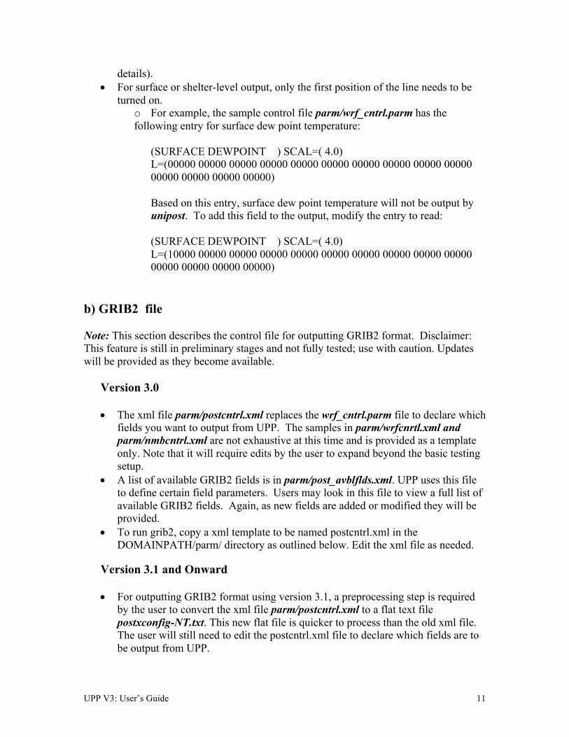
details). • For surface or shelter-level output, only the first position of the line needs to be
turned on. o For example, the sample control file parm/wrf_cntrl.parm has the following entry for surface dew point temperature:
(SURFACE DEWPOINT ) SCAL=( 4.0) L=(00000 00000 00000 00000 00000 00000 00000 00000 00000 00000 00000 00000 00000 00000) Based on this entry, surface dew point temperature will not be output by unipost. To add this field to the output, modify the entry to read: (SURFACE DEWPOINT ) SCAL=( 4.0) L=(10000 00000 00000 00000 00000 00000 00000 00000 00000 00000 00000 00000 00000 00000)
b) GRIB2 file Note: This section describes the control file for outputting GRIB2 format. Disclaimer: This feature is still in preliminary stages and not fully tested; use with caution. Updates will be provided as they become available.
Version 3.0
• The xml file parm/postcntrl.xml replaces the wrf_cntrl.parm file to declare which fields you want to output from UPP. The samples in parm/wrfcnrtl.xml and parm/nmbcntrl.xml are not exhaustive at this time and is provided as a template only. Note that it will require edits by the user to expand beyond the basic testing setup.
• A list of available GRIB2 fields is in parm/post_avblflds.xml. UPP uses this file to define certain field parameters. Users may look in this file to view a full list of available GRIB2 fields. Again, as new fields are added or modified they will be provided.
• To run grib2, copy a xml template to be named postcntrl.xml in the DOMAINPATH/parm/ directory as outlined below. Edit the xml file as needed.
Version 3.1 and Onward
• For outputting GRIB2 format using version 3.1, a preprocessing step is required by the user to convert the xml file parm/postcntrl.xml to a flat text file postxconfig-NT.txt. This new flat file is quicker to process than the old xml file. The user will still need to edit the postcntrl.xml file to declare which fields are to be output from UPP.
UPP V3: User’s Guide 12
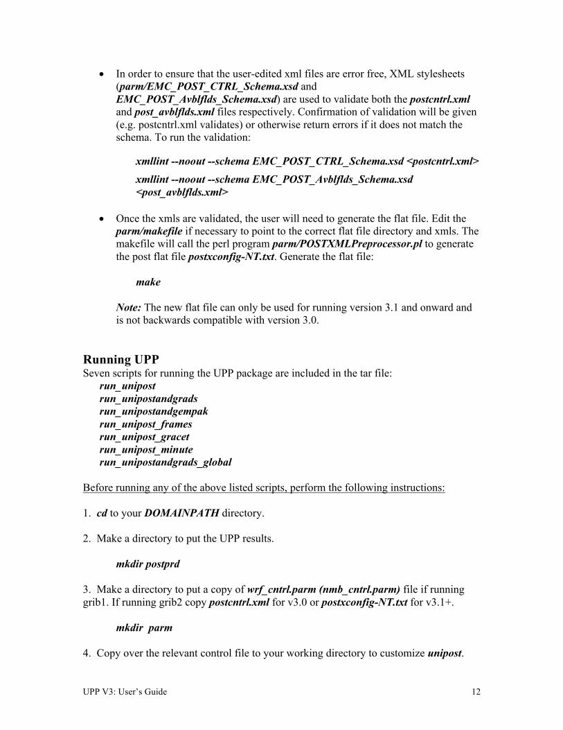
• In order to ensure that the user-edited xml files are error free, XML stylesheets (parm/EMC_POST_CTRL_Schema.xsd and EMC_POST_Avblflds_Schema.xsd) are used to validate both the postcntrl.xml and post_avblflds.xml files respectively. Confirmation of validation will be given (e.g. postcntrl.xml validates) or otherwise return errors if it does not match the schema. To run the validation:
xmllint --noout --schema EMC_POST_CTRL_Schema.xsd <postcntrl.xml> xmllint --noout --schema EMC_POST_Avblflds_Schema.xsd <post_avblflds.xml>
• Once the xmls are validated, the user will need to generate the flat file. Edit the
parm/makefile if necessary to point to the correct flat file directory and xmls. The makefile will call the perl program parm/POSTXMLPreprocessor.pl to generate the post flat file postxconfig-NT.txt. Generate the flat file:
make
Note: The new flat file can only be used for running version 3.1 and onward and is not backwards compatible with version 3.0.
Running UPP Seven scripts for running the UPP package are included in the tar file:
run_unipost run_unipostandgrads run_unipostandgempak run_unipost_frames run_unipost_gracet run_unipost_minute run_unipostandgrads_global
Before running any of the above listed scripts, perform the following instructions: 1. cd to your DOMAINPATH directory. 2. Make a directory to put the UPP results.
mkdir postprd 3. Make a directory to put a copy of wrf_cntrl.parm (nmb_cntrl.parm) file if running grib1. If running grib2 copy postcntrl.xml for v3.0 or postxconfig-NT.txt for v3.1+.
mkdir parm 4. Copy over the relevant control file to your working directory to customize unipost.

UPP V3: User’s Guide 13
For Grib1, copy the default UPPV3.2/parm/wrf_cntrl.parm (nmb_cntrl.parm) file For Grib2, copy a template UPPV3.0/parm/wrfcntrl.xml (nmbcntrl.xml) file to be named postcntrl.xml if using v3.0 or UPPV3.2/parm/postxconfig-NT_WRF.txt (postxconfig-NT_NMB.txt) to be named postxconfig-NT.txt if using v3.1+. 5. Edit the wrf_cntrl.parm (nmb_cntrl.parm) file to reflect the fields and levels you want unipost to output. (For Grib2: Edit the postcntrl.xml file for v3.0 or the postxconfig-NT.txt file for v3.1+) 6. Copy over the (UPPV3.2/scripts/run_unipost*) script of your choice to the postprd/. 7. Edit the run script as outlined below. Once these directories are set up and the edits outlined below are complete, the scripts can be run interactively from the postprd directory by simply typing the script name on the command line. Overview of the scripts to run the UPP Note: It is recommended that the user refer to the run_unipost* scripts in the script/ while reading this overview. Since V3.0, user modified variables are now all contained at the top of the run_unipost* script in one user-edit section, along with a brief description. Descriptions below follow the run_unipost script.
1. Set up basic path variables: TOP_DIR : Top level directory for source codes (UPPV3.2 and WRFV3) DOMAINPATH : Working directory for this run WRFPATH : Location of compiled WRFV3 UNIPOST_HOME : Location of the UPPV3.2 build directory POSTEXEC : Location of the UPPV3.2 executables modelDataPath : Location of the model output data files to be processed (e.g.
"wrfprd/" for WRF-based runs; "nemsprd/" for NMMB forecasts). paramFile : Name and location of cntrl.parm (wrf_cntrl.parm or
nmb_cntrl.parm) text file that lists desired fields for GRIB1 output. Template in UPPV3.2/parm/
xmlCntrlFile : Name and location of postcntrl.xml. XML file that lists desired fields for GRIB2 output. For V3.0, this file is read directly by UPP; for V3.1+ this file is used to create the new text file read by UPP. Templates in UPPV3.2/parm/wrfcntrl.xml or UPPV3.2/parm/nmbcntrl.xml
txtCntrlFile : Name and location of postxconfig-NT.txt file that lists desired fields for GRIB2 format for version 3.1+. This file is generated by the user following the steps list above.

UPP V3: User’s Guide 14
Note: The scripts are configured such that unipost expects the WRF history files (wrfout* files) to be in wrfprd/, the wrf_cntrl.parm (postcntrl.xml or postxconfig-NT.txt) file to be in parm/ and the postprocessor working directory to be called postprd/, all under DOMAINPATH. Similarly with NMMB, NMMB history files (nmmb_hist*) are to be in nemsprd/, nmb_cntrl.parm (postcntrl.xml or postxconfig-NT.txt) file to be in parm, and the output to be in postprd, all under DOMAINPATH. This set up is for user convenience to have a script ready to run, paths may be modified but be sure to check run script to make sure settings are correct.
2. Specify dynamic core being run (“NMM” or “ARW” or “NMB”)
dyncore : What model core is used (“NMM” or “ARW” or “NMB”)
3. Specify the format for the input model files and output UPP files. inFormat : Format of the model data arw – “netcdf” nmm – “netcdf” nmb – “binarynemsio” outFormat : Format of output from UPP grib grib2 - NOTE: GRIB2 is not extensively tested, use with caution. No GRIB2 destaggering support for NMB or NMM grids; Suggested use with ARW only at this time.
4. Specify the forecast cycles to be post-processed
startdate : Forecast start date (YYYYMMDDHH) fhr : First forecast hour to be post-processed lastfhr : Last forecast hour to be post-processed incrementhr : Increment (in hours) between forecast files * Do not set to 0 or the script will loop continuously *
5. Set up how many domains will be post-processed
domain_list : List of domains for run (e.g. “d01 d02”)
6. Set/uncomment the run command for your system. (i.e. serial, mpirun, etc). RUN_COMMAND : System run command for serial or parallel runs
• The default execution command in the distributed scripts is for a single processor: ./unipost.exe > unipost_${domain}.${fhr}.out 2>&1.
• To run unipost using mpi (dmpar compilation), the command line should be: >> LINUX-MPI systems: mpirun -np N unipost.exe > outpost 2>&1 (Note: on some systems a host file also needs to be specified: –machinefile “host”) >> IBM: mpirun.lsf unipost.exe < itag > outpost

UPP V3: User’s Guide 15
7. Set copygb grid definitions (mandatory for NMM or NMMB)
copygb_opt : Copygb grid option to destagger and regrid NMM or NMB "lambert" = Grid spec for copygb generated internally for lambert data Reads copygb_gridnav.txt "lat-lon" = Grid spec for copygb generated internally for lat-lon data Reads copygb_hwrf.txt "awips" = Use a predefined awips grid, e.g. 212 ** Uncomment "export awips_id= " and add desired grid number. "custom" = Specify your own grid ** Uncomment "export custom_gds= " and add grid description.
Note: More information about copygb is provided below under “Examples of copygb”. Copygb runs on GRIB1 format only. For GRIB2 format, wgrib2 is required, with more information provided below under “Examples of wgrib2”.
8. Set naming convention for prefix and extension of output file name i. comsp is the initial string of the output file name (by default it is not set and the prefix of the output file will be the string set in wrf_cntrl.parm (nmb_cntrl.parm) DATSET, if set it will concatenate the setting to the front of the string specified in wrf_cntrl.parm (nmb_cntrl.parm) DATSET) ii. tmmark is used for the file extension (in run_unipost, tmmark=tm00, if not set, it is set to .GrbF)
Since V3.0, the itag that will be read in by unipost.exe from stdin (unit 5) is generated automatically in the run_unipost script based on the user-defined options above. It should not be necessary to edit this. For description purposes, the namelist (itag) contains 5 lines:
i. Name of the WRF or NMB output file to be posted. ii. Format of WRF or NMB model output (netcdf, binarynemsio). iii. Format of UPP output (GRIB1 or GRIB2) iv. Forecast valid time (not model start time) in WRF or NMB format (the forecast time desired to be post-processed). v. Dynamic core used (NMM or NCAR).
Note: With the addition of GRIB2 output capabilities, a fifth line has been added to the namelist. If the third line (i.e., UPP output type) is not set, UPP will default the output file format to “grib1”.
If scripts run_unipostandgrads or run_unipostandgempak are used, additional steps are taken to create image files (see Visualization section below). Upon a successful run, unipost and copygb will generate output files WRFPRS_dnn.hh (NMBPRS_dnn.hh )and wrfprs_dnn.hh (nmbprs_dnn.hh), respectively, in the post-processor working directory, where “nn” refers to the domain id and “hh” denotes the forecast hour. In addition, the script run_unipostandgrads will produce a suite of png

UPP V3: User’s Guide 16
images named variablehh_GrADS.png, and the script run_unipostandgempak will produce a suite of gif images named variablehh.gif. If the run did not complete successfully, a log file in the post-processor working directory called unipost_dnn.hh.out, where “nn” is the domain id and “hh” is the forecast hour, may be consulted for further information. Examples of copygb
Sample command line for calling copygb: copygb.exe –xg“grid [kgds]” input_file output_file where grid refers to the output grid to which the native forecast is being interpolated.
The output grid can be specified in three ways: i. As the grid id of a pre-defined AWIPS grid number (gridno):
copygb.exe -g${gridno} -x input_file output_file
For example, using grid 218: copygb.exe -xg“218” WRFPRS_$domain.${fhr} wrfprs_$domain .${fhr}
ii. As a user defined standard grid, such as for grid 255:
copygb.exe –xg“255 kgds” input_file output_file where the user defined grid is specified by a full set of kgds parameters
determining a GRIB GDS (grid description section) in the W3fi63 format. Details on how to specify the kgds parameters are documented in file lib/w3lib/w3fi71.f. For example:
copygb.exe -xg“ 255 3 109 91 37719 -77645 8 -71000 10433 9966 0 64 42000 42000” WRFPRS_$domain.${fhr} wrfprs_$domain.${fhr}
iii. From a file: When WRF-NMM output is processed by unipost, two text
files, copygb_gridnav.txt and copygb_hwrf.txt, are created. These files contain the GRID GDS of a Lambert Conformal Grid (file copygb_gridnav.txt) or lat/lon grid (copygb_hwrf.txt) similar in domain and grid spacing to the one used to run the WRF-NMM model. The contents of one of these files are read into variable nav and can be used as input to copygb.exe.
copygb.exe -xg“$nav” input_file output_file
For example, when using “copygb_gridnav.txt” for an application, the steps
UPP V3: User’s Guide 17
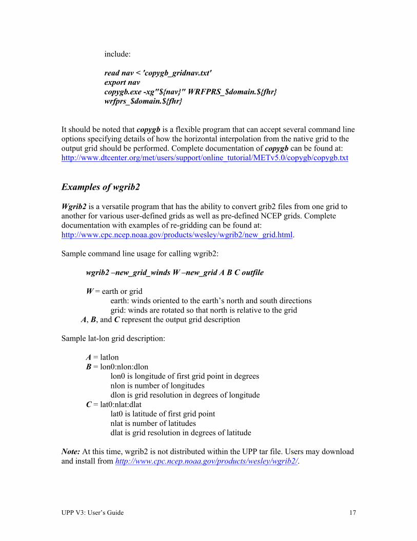
include: read nav < 'copygb_gridnav.txt' export nav copygb.exe -xg"${nav}" WRFPRS_$domain.${fhr} wrfprs_$domain.${fhr}
It should be noted that copygb is a flexible program that can accept several command line options specifying details of how the horizontal interpolation from the native grid to the output grid should be performed. Complete documentation of copygb can be found at: http://www.dtcenter.org/met/users/support/online_tutorial/METv5.0/copygb/copygb.txt Examples of wgrib2 Wgrib2 is a versatile program that has the ability to convert grib2 files from one grid to another for various user-defined grids as well as pre-defined NCEP grids. Complete documentation with examples of re-gridding can be found at: http://www.cpc.ncep.noaa.gov/products/wesley/wgrib2/new_grid.html. Sample command line usage for calling wgrib2: wgrib2 –new_grid_winds W –new_grid A B C outfile
W = earth or grid earth: winds oriented to the earth’s north and south directions
grid: winds are rotated so that north is relative to the grid A, B, and C represent the output grid description
Sample lat-lon grid description: A = latlon B = lon0:nlon:dlon lon0 is longitude of first grid point in degrees nlon is number of longitudes dlon is grid resolution in degrees of longitude C = lat0:nlat:dlat lat0 is latitude of first grid point nlat is number of latitudes dlat is grid resolution in degrees of latitude Note: At this time, wgrib2 is not distributed within the UPP tar file. Users may download and install from http://www.cpc.ncep.noaa.gov/products/wesley/wgrib2/.

UPP V3: User’s Guide 18
Visualization with UPP GEMPAK The GEMPAK utility nagrib is able to decode GRIB files whose navigation is on any non-staggered grid. Hence, GEMPAK is able to decode GRIB files generated by the UPP package and plot horizontal fields or vertical cross sections. A sample script named run_unipostandgempak, which is included in the scripts directory of the tar file, can be used to run unipost, copygb, and plot the following fields using GEMPAK:
• Sfcmap_dnn_hh.gif: mean SLP and 6 hourly precipitation • PrecipType_dnn_hh.gif: precipitation type (just snow and rain) • 850mbRH_dnn_hh.gif: 850 mb relative humidity • 850mbTempandWind_dnn_hh.gif: 850 mb temperature and wind vectors • 500mbHandVort_dnn_hh.gif: 500 mb geopotential height and vorticity • 250mbWindandH_dnn_hh.gif: 250 mb wind speed isotacs and geopotential
height This script can be modified to customize fields for output. GEMPAK has an online users guide at http://www.unidata.ucar.edu/software/gempak/help_and_documentation/manual/. In order to use the script run_unipostandgempak, it is necessary to set the environment variable GEMEXEC to the path of the GEMPAK executables. For example,
setenv GEMEXEC /usr/local/gempak/bin
Note: For GEMPAK, the precipitation accumulation period for WRF-NMM is given by the variable incrementhr in the run_unipostandgempak script. GrADS The GrADS utilities grib2ctl.pl (g2ctl.pl) and gribmap are able to decode GRIB1 (GRIB2) files whose navigation is on any non-staggered grid. These utilities and instructions on how to use them to generate GrADS control files are available from: http://www.cpc.ncep.noaa.gov/products/wesley/grib2ctl.html for GRIB1 and http://www.cpc.ncep.noaa.gov/products/wesley/g2ctl.html for GRIB2. The GrADS package is available from: http://cola.gmu.edu/grads/gadoc/gadoc.php. GrADS has an online User’s Guide at: http://cola.gmu.edu/grads/gadoc/users.html and a list of basic commands for GrADS can be found at: http://cola.gmu.edu/grads/gadoc/reference_card.pdf. A sample script named run_unipostandgrads, which is included in the scripts directory
UPP V3: User’s Guide 19
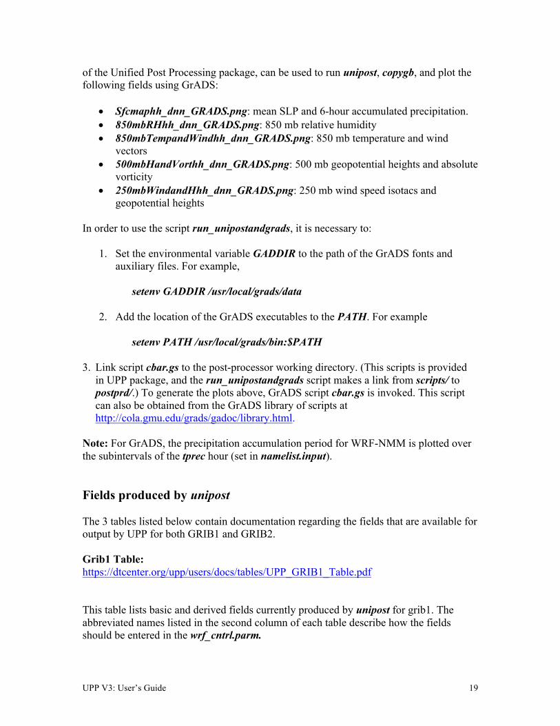
of the Unified Post Processing package, can be used to run unipost, copygb, and plot the following fields using GrADS:
• Sfcmaphh_dnn_GRADS.png: mean SLP and 6-hour accumulated precipitation. • 850mbRHhh_dnn_GRADS.png: 850 mb relative humidity • 850mbTempandWindhh_dnn_GRADS.png: 850 mb temperature and wind
vectors • 500mbHandVorthh_dnn_GRADS.png: 500 mb geopotential heights and absolute
vorticity • 250mbWindandHhh_dnn_GRADS.png: 250 mb wind speed isotacs and
geopotential heights In order to use the script run_unipostandgrads, it is necessary to:
1. Set the environmental variable GADDIR to the path of the GrADS fonts and auxiliary files. For example,
setenv GADDIR /usr/local/grads/data
2. Add the location of the GrADS executables to the PATH. For example setenv PATH /usr/local/grads/bin:$PATH
3. Link script cbar.gs to the post-processor working directory. (This scripts is provided in UPP package, and the run_unipostandgrads script makes a link from scripts/ to postprd/.) To generate the plots above, GrADS script cbar.gs is invoked. This script can also be obtained from the GrADS library of scripts at http://cola.gmu.edu/grads/gadoc/library.html.
Note: For GrADS, the precipitation accumulation period for WRF-NMM is plotted over the subintervals of the tprec hour (set in namelist.input). Fields produced by unipost The 3 tables listed below contain documentation regarding the fields that are available for output by UPP for both GRIB1 and GRIB2. Grib1 Table: https://dtcenter.org/upp/users/docs/tables/UPP_GRIB1_Table.pdf This table lists basic and derived fields currently produced by unipost for grib1. The abbreviated names listed in the second column of each table describe how the fields should be entered in the wrf_cntrl.parm.
UPP V3: User’s Guide 20
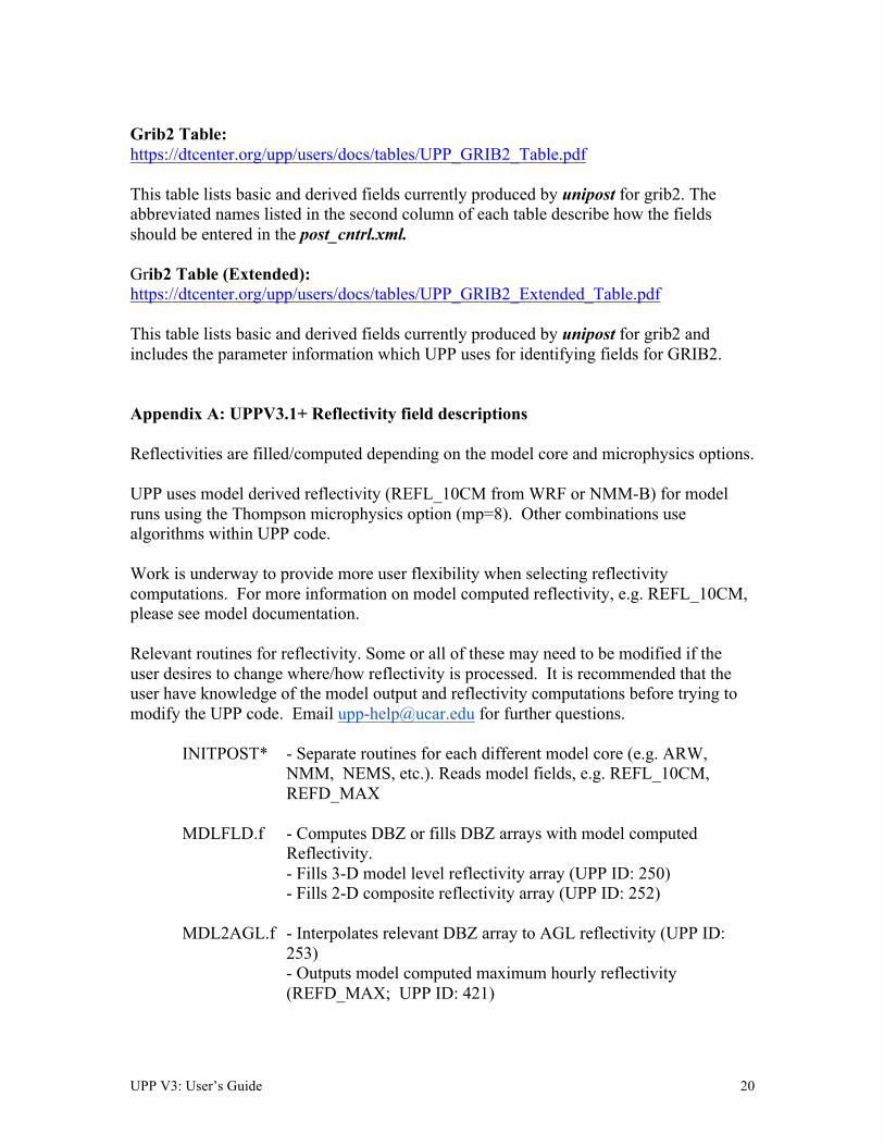
Grib2 Table: https://dtcenter.org/upp/users/docs/tables/UPP_GRIB2_Table.pdf This table lists basic and derived fields currently produced by unipost for grib2. The abbreviated names listed in the second column of each table describe how the fields should be entered in the post_cntrl.xml. Grib2 Table (Extended): https://dtcenter.org/upp/users/docs/tables/UPP_GRIB2_Extended_Table.pdf This table lists basic and derived fields currently produced by unipost for grib2 and includes the parameter information which UPP uses for identifying fields for GRIB2. Appendix A: UPPV3.1+ Reflectivity field descriptions Reflectivities are filled/computed depending on the model core and microphysics options. UPP uses model derived reflectivity (REFL_10CM from WRF or NMM-B) for model runs using the Thompson microphysics option (mp=8). Other combinations use algorithms within UPP code. Work is underway to provide more user flexibility when selecting reflectivity computations. For more information on model computed reflectivity, e.g. REFL_10CM, please see model documentation. Relevant routines for reflectivity. Some or all of these may need to be modified if the user desires to change where/how reflectivity is processed. It is recommended that the user have knowledge of the model output and reflectivity computations before trying to modify the UPP code. Email [email protected] for further questions.
INITPOST* - Separate routines for each different model core (e.g. ARW, NMM, NEMS, etc.). Reads model fields, e.g. REFL_10CM, REFD_MAX
MDLFLD.f - Computes DBZ or fills DBZ arrays with model computed
Reflectivity. - Fills 3-D model level reflectivity array (UPP ID: 250) - Fills 2-D composite reflectivity array (UPP ID: 252)
MDL2AGL.f - Interpolates relevant DBZ array to AGL reflectivity (UPP ID:
253) - Outputs model computed maximum hourly reflectivity (REFD_MAX; UPP ID: 421)
UPP V3: User’s Guide 21
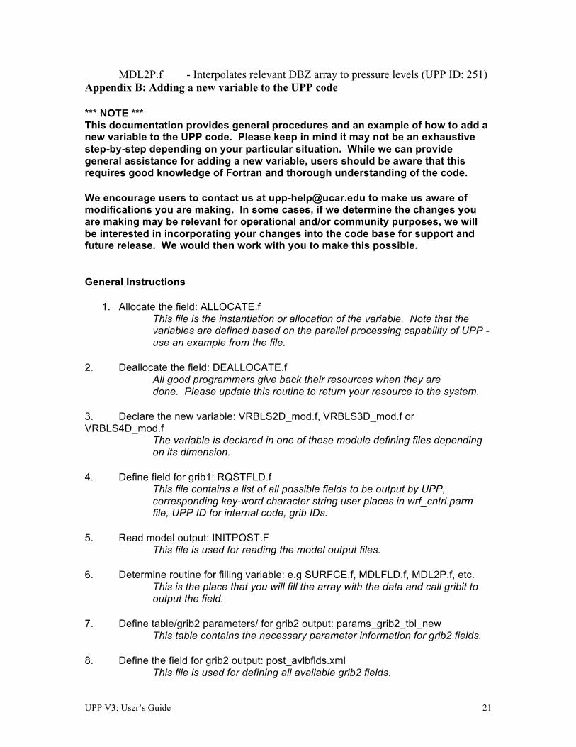
MDL2P.f - Interpolates relevant DBZ array to pressure levels (UPP ID: 251) Appendix B: Adding a new variable to the UPP code
*** NOTE *** This documentation provides general procedures and an example of how to add a new variable to the UPP code. Please keep in mind it may not be an exhaustive step-by-step depending on your particular situation. While we can provide general assistance for adding a new variable, users should be aware that this requires good knowledge of Fortran and thorough understanding of the code. We encourage users to contact us at [email protected] to make us aware of modifications you are making. In some cases, if we determine the changes you are making may be relevant for operational and/or community purposes, we will be interested in incorporating your changes into the code base for support and future release. We would then work with you to make this possible.
General Instructions
1. Allocate the field: ALLOCATE.f This file is the instantiation or allocation of the variable. Note that the variables are defined based on the parallel processing capability of UPP - use an example from the file.
2. Deallocate the field: DEALLOCATE.f
All good programmers give back their resources when they are done. Please update this routine to return your resource to the system.
3. Declare the new variable: VRBLS2D_mod.f, VRBLS3D_mod.f or VRBLS4D_mod.f
The variable is declared in one of these module defining files depending on its dimension.
4. Define field for grib1: RQSTFLD.f
This file contains a list of all possible fields to be output by UPP, corresponding key-word character string user places in wrf_cntrl.parm file, UPP ID for internal code, grib IDs.
5. Read model output: INITPOST.F
This file is used for reading the model output files. 6. Determine routine for filling variable: e.g SURFCE.f, MDLFLD.f, MDL2P.f, etc.
This is the place that you will fill the array with the data and call gribit to output the field.
7. Define table/grib2 parameters/ for grib2 output: params_grib2_tbl_new
This table contains the necessary parameter information for grib2 fields. 8. Define the field for grib2 output: post_avlbflds.xml
This file is used for defining all available grib2 fields.

UPP V3: User’s Guide 22
9. Define control file entry for output: postcntrl.xml & postxconfig-NT.txt
These files are used for controlling which fields are output by UPP for grib2.
10. Define output control file: wrf_cntrl.parm
This file is used for controlling which fields are output by UPP for grib1.
Example Procedure: Steps for adding the new variable ‘ACLHF’
• This example illustrates a new variable from the WRF output that will be read into UPP and directly output into the grib output files (i.e. no additional computations/calculations are needed for the field).
• Note that while grib1 procedures are provided, we have moved to grib2 almost exclusively. As such support for grib1 additions is limited.
• Additions to each of the routines are highlighted in green. • Locations of routines are in /UPPV3.2/src/unipost unless specified otherwise. • A sample wrfout file for the following procedures is available for download from:
o https://dtcenter.org/upp/users/downloads/data/AddNewVariableData.tar.gz
o This data is the 6-hr forecast of a WRF initialization of 2009-12-17_12:00:00
New variable to add: ACLHF
float ACLHF(Time, south_north, west_east) ; ACLHF:FieldType = 104 ; ACLHF:MemoryOrder = "XY " ; ACLHF:description = "ACCUMULATED UPWARD LATENT HEAT FLUX AT THE SURFACE" ; ACLHF:units = "J m-2" ; ACLHF:stagger = "" ; ACLHF:coordinates = "XLONG XLAT" ;
1. Allocate the new variable in ALLOCATE_ALL.f This file is the instantiation or allocation of the variable. Note that the variables are defined based on the parallel processing capability of UPP - use an example from the file. User procedure:
• Add in VRBLS2D section as: allocate(aclhf(im,jsta_2l:jend_2u)) 2. De-allocate the variable to give the resources back in DEALLOCATE.f All good programmers give back their resources when they are done. Please update this routine to return your resource to the system. User procedure:
UPP V3: User’s Guide 23
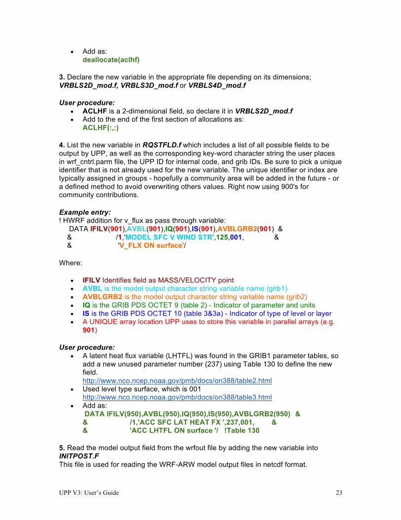
• Add as: deallocate(aclhf) 3. Declare the new variable in the appropriate file depending on its dimensions; VRBLS2D_mod.f, VRBLS3D_mod.f or VRBLS4D_mod.f User procedure:
• ACLHF is a 2-dimensional field, so declare it in VRBLS2D_mod.f • Add to the end of the first section of allocations as:
ACLHF(:,:) 4. List the new variable in RQSTFLD.f which includes a list of all possible fields to be output by UPP, as well as the corresponding key-word character string the user places in wrf_cntrl.parm file, the UPP ID for internal code, and grib IDs. Be sure to pick a unique identifier that is not already used for the new variable. The unique identifier or index are typically assigned in groups - hopefully a community area will be added in the future - or a defined method to avoid overwriting others values. Right now using 900's for community contributions. Example entry: ! HWRF addition for v_flux as pass through variable: DATA IFILV(901),AVBL(901),IQ(901),IS(901),AVBLGRB2(901) & & /1,'MODEL SFC V WIND STR’,125,001, & & 'V_FLX ON surface’/ Where:
• IFILV Identifies field as MASS/VELOCITY point • AVBL is the model output character string variable name (grib1) • AVBLGRB2 is the model output character string variable name (grib2) • IQ is the GRIB PDS OCTET 9 (table 2) - Indicator of parameter and units • IS is the GRIB PDS OCTET 10 (table 3&3a) - Indicator of type of level or layer • A UNIQUE array location UPP uses to store this variable in parallel arrays (e.g.
901) User procedure:
• A latent heat flux variable (LHTFL) was found in the GRIB1 parameter tables, so add a new unused parameter number (237) using Table 130 to define the new field. http://www.nco.ncep.noaa.gov/pmb/docs/on388/table2.html
• Used level type surface, which is 001 http://www.nco.ncep.noaa.gov/pmb/docs/on388/table3.html
• Add as: DATA IFILV(950),AVBL(950),IQ(950),IS(950),AVBLGRB2(950) & & /1,'ACC SFC LAT HEAT FX ',237,001, & & 'ACC LHTFL ON surface '/ !Table 130 5. Read the model output field from the wrfout file by adding the new variable into INITPOST.F This file is used for reading the WRF-ARW model output files in netcdf format.
UPP V3: User’s Guide 24
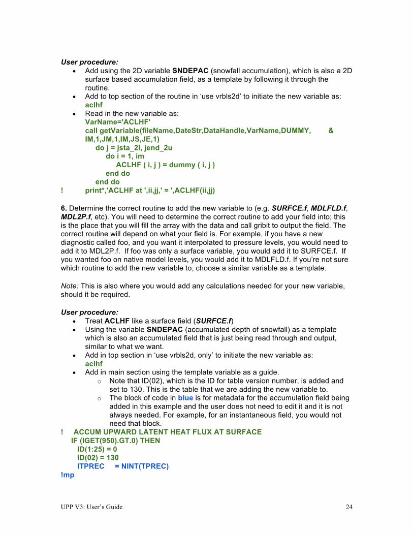
User procedure:
• Add using the 2D variable SNDEPAC (snowfall accumulation), which is also a 2D surface based accumulation field, as a template by following it through the routine.
• Add to top section of the routine in ‘use vrbls2d’ to initiate the new variable as: aclhf
• Read in the new variable as: VarName='ACLHF' call getVariable(fileName,DateStr,DataHandle,VarName,DUMMY, & IM,1,JM,1,IM,JS,JE,1) do j = jsta_2l, jend_2u do i = 1, im ACLHF ( i, j ) = dummy ( i, j ) end do end do ! print*,'ACLHF at ',ii,jj,' = ',ACLHF(ii,jj) 6. Determine the correct routine to add the new variable to (e.g. SURFCE.f, MDLFLD.f, MDL2P.f, etc). You will need to determine the correct routine to add your field into; this is the place that you will fill the array with the data and call gribit to output the field. The correct routine will depend on what your field is. For example, if you have a new diagnostic called foo, and you want it interpolated to pressure levels, you would need to add it to MDL2P.f. If foo was only a surface variable, you would add it to SURFCE.f. If you wanted foo on native model levels, you would add it to MDLFLD.f. If you’re not sure which routine to add the new variable to, choose a similar variable as a template. Note: This is also where you would add any calculations needed for your new variable, should it be required. User procedure:
• Treat ACLHF like a surface field (SURFCE.f) • Using the variable SNDEPAC (accumulated depth of snowfall) as a template
which is also an accumulated field that is just being read through and output, similar to what we want.
• Add in top section in ‘use vrbls2d, only’ to initiate the new variable as: aclhf
• Add in main section using the template variable as a guide. o Note that ID(02), which is the ID for table version number, is added and
set to 130. This is the table that we are adding the new variable to. o The block of code in blue is for metadata for the accumulation field being
added in this example and the user does not need to edit it and it is not always needed. For example, for an instantaneous field, you would not need that block.
! ACCUM UPWARD LATENT HEAT FLUX AT SURFACE IF (IGET(950).GT.0) THEN ID(1:25) = 0 ID(02) = 130 ITPREC = NINT(TPREC) !mp

UPP V3: User’s Guide 25
IF(ITPREC .NE. 0) THEN IFINCR = MOD(IFHR,ITPREC) IF(IFMIN .GE. 1)IFINCR = MOD(IFHR*60+IFMIN,ITPREC*60) ELSE IFINCR = 0 ENDIF !mp ID(18) = 0 ID(19) = IFHR IF(IFMIN .GE. 1)ID(19)=IFHR*60+IFMIN ID(20) = 4 IF (IFINCR.EQ.0) THEN ID(18) = IFHR-ITPREC ELSE ID(18) = IFHR-IFINCR IF(IFMIN .GE. 1)ID(18)=IFHR*60+IFMIN-IFINCR ENDIF IF (ID(18).LT.0) ID(18) = 0 if(grib=='grib1') then DO J=JSTA,JEND DO I=1,IM GRID1(I,J) = ACLHF(I,J) ENDDO ENDDO CALL GRIBIT(IGET(950),LVLS(1,IGET(950)), GRID1,IM,JM) elseif(grib=='grib2') then cfld=cfld+1 fld_info(cfld)%ifld=IAVBLFLD(IGET(950)) fld_info(cfld)%ntrange=1 fld_info(cfld)%tinvstat=IFHR-ID(18) !$omp parallel do private(i,j,jj) do j=1,jend-jsta+1 jj = jsta+j-1 do i=1,im datapd(i,j,cfld) = ACLHF(i,jj) enddo enddo endif ENDIF 7. For grib2 output, add the new variable to /UPPV3.2/src/lib/g2tmpl/params_grib2_tbl_new. For all current UPP output fields, this table lists, in order, the:
• Discipline (http://www.nco.ncep.noaa.gov/pmb/docs/grib2/grib2_table0-0.shtml) • Category (http://www.nco.ncep.noaa.gov/pmb/docs/grib2/grib2_table4-1.shtml) • Parameter Number (http://www.nco.ncep.noaa.gov/pmb/docs/grib2/grib2_table4-
2.shtml) • Table information (0 for parameters from the WMO table; 1 for parameters from
the local NCEP table) • Abbreviated Variable Name (from the parameters table)
UPP V3: User’s Guide 26
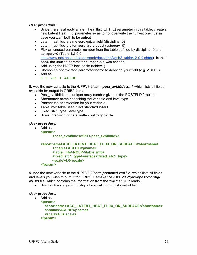
User procedure: • Since there is already a latent heat flux (LHTFL) parameter in this table, create a
new Latent Heat Flux parameter so as to not overwrite the current one, just in case you want both to be output
• Latent heat flux is a meteorological field (discipline=0) • Latent heat flux is a temperature product (category=0) • Pick an unused parameter number from the table defined by discipline=0 and
category=0 (Table 4.2-0-0: http://www.nco.ncep.noaa.gov/pmb/docs/grib2/grib2_table4-2-0-0.shtml). In this case, the unused parameter number 205 was chosen.
• Add using the NCEP local table (table=1) • Choose an abbreviated parameter name to describe your field (e.g. ACLHF) • Add as:
0 0 205 1 ACLHF 8. Add the new variable to the /UPPV3.2/parm/post_avblflds.xml, which lists all fields available for output in GRIB2 format.
• Post_avblfldidx: the unique array number given in the RQSTFLD.f routine. • Shortname: name describing the variable and level type • Pname: the abbreviation for your variable • Table info: table used if not standard WMO • Fixed_sfc1_type: level type • Scale: precision of data written out to grib2 file
User procedure:
• Add as: <param> <post_avblfldidx>950</post_avblfldidx> <shortname>ACC_LATENT_HEAT_FLUX_ON_SURFACE</shortname> <pname>ACLHF</pname>
<table_info>NCEP</table_info> <fixed_sfc1_type>surface</fixed_sfc1_type> <scale>4.0</scale> </param> 9. Add the new variable to the /UPPV3.2/parm/postcntrl.xml file, which lists all fields and levels you wish to output for GRIB2. Remake the /UPPV3.2/parm/postxconfig-NT.txt file, which contains the information from the xml that UPP reads.
• See the User’s guide on steps for creating the text control file User procedure:
• Add as: <param> <shortname>ACC_LATENT_HEAT_FLUX_ON_SURFACE</shortname> <pname>ACLHF</pname> <scale>4.0</scale> </param>

UPP V3: User’s Guide 27
10. Add the new variable to the /UPPV3.2/parm/wrf_cntrl.parm file, which lists all fields and levels you wish to output for GRIB1. User procedure:
• Add as: (ACC SFC LAT HEAT FX ) SCAL=( 4.0) L=(10000 00000 00000 00000 00000 00000 00000 00000 00000 00000 00000 00000 00000 00000) ** Note the first entry is turned from 0 to 1. This turns on the first level. 11. Run clean on the code and recompile the code to include the changes before running your UPP run script. User procedure: >> ./clean -a >> ./configure >> ./compile >& compile.log & 12. Assuming the modified code compiled successfully and you were able to produce grib output, you can check the grib file for your new variable. GRIB2 output of the new variable from this example procedure (using the wgrib2 utility if available on your system).
• The new variable will not be defined by the variable name. Instead it will be defined using the grib2 parameter information you entered into params_grib2_tbl_new from step 7 of this procedure.
456:43204412:vt=2009121718:surface:6 hour fcst:var discipline=0 center=7 local_table=1 parmcat=0 parm=205: ndata=121002:undef=0:mean=1.97108e+06:min=-1.12e+06:max=2.406e+07 grid_template=30:winds(grid): Lambert Conformal: (402 x 301) input WE:SN output WE:SN res 8 Lat1 14.807213 Lon1 231.818604 LoV 258.040009 LatD 38.270000 Latin1 38.270000 Latin2 38.270000 LatSP 0.000000 LonSP 0.000000 North Pole (402 x 301) Dx 15000.000000 m Dy 15000.000000 m mode 8 GRIB1 output of the new variable from this example procedure (using the wgrib utility if available on your system).
• The new variable will not be defined by the variable name. Instead it is defined by kpds5=237 (grib1 ID) and kpds6=1 (level type) you gave it in RQSTFLD.f in step 4.
• For this particular variable, the accumulation period is shown, due to the addition of the metadata block in the SURFCE.f routine.
rec 319:59903982:date 2009121712 var237 kpds5=237 kpds6=1 kpds7=0 levels=(0,0) grid=255 sfc 0-24hr acc: var237=undefined timerange 0 P1 6 P2 0 TimeU 1 nx 402 ny 301 GDS grid 3 num_in_ave 0 missing 0 center 7 subcenter 0 process 125 Table 130 scan: WE:SN winds(grid)
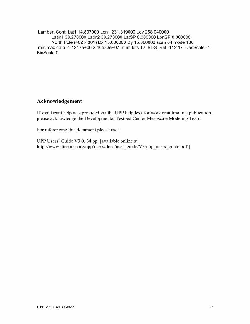
UPP V3: User’s Guide 28
Lambert Conf: Lat1 14.807000 Lon1 231.819000 Lov 258.040000 Latin1 38.270000 Latin2 38.270000 LatSP 0.000000 LonSP 0.000000 North Pole (402 x 301) Dx 15.000000 Dy 15.000000 scan 64 mode 136 min/max data -1.1217e+06 2.40583e+07 num bits 12 BDS_Ref -112.17 DecScale -4 BinScale 0 Acknowledgement If significant help was provided via the UPP helpdesk for work resulting in a publication, please acknowledge the Developmental Testbed Center Mesoscale Modeling Team. For referencing this document please use: UPP Users’ Guide V3.0, 34 pp. [available online at http://www.dtcenter.org/upp/users/docs/user_guide/V3/upp_users_guide.pdf ]