usermanual - sonmicro online storesonmicro.com/en/downloads/s125/usermanual.pdf · user manual 44...
TRANSCRIPT

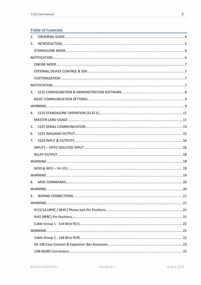
S125 Multi-Purpose 125 KHz RFID Reader
USER MANUAL 44 mm
84 mm
� 125 KHz RFID EM4100/2 Cards & Tags
� Online & Standalone Operation 1
� Built-In E2PROM Memory up to 1000 Users 1
� Teach & Delete with Master Card 1
� Fully customizable & Firmware Upgrade-able 2
� Appropriate for Wall-Mount
� Compatible with SonMicro’s SAC 900 Control Panel
� Easy & Smooth wiring accessories available
� 9V/24V DC Operating Voltage, AC (optional) 3
� RS232/485 Interface 9600bps to 115200bps 4
� Wiegand Interface (26/34/42 bits)
� 1x 60W Relay Output (NO, NC, COM) 5
� 1x Opto-Isolated Input 5
� Built-In Buzzer & Duo Color LED
� 2x General Purpose I/O instead of Wiegand
� Advanced & Intelligent SingleWire Input Control 6
1 Standalone operation is available only on S125-E Series
2 Hardware and Firmware customization is available. “No Name” service is available for OEMs
3 SA-100 Connector accessory includes built-in AC/DC regulator for AC Voltage inputs. (Solds seperately)
4 RS232 and RS485 comes as different products and are not supported at the same time
5 Two of the Wiegand Data Line can be converted to 5V Inputs or Outputs in Configuration Software.
6 Inputs can detect and warn if state is high or low. Pulses on input wire can be counted
MULTI PURPOSE
ONLINE & OFFLINE
MODE
BUILT-IN
RELAY
S125 User Manual 2
SonMicro Electronics Revision A.1 August, 2010
Table of Contents
1. ORDERING GUIDE ...................................................................................................................... 4
2. INTRODUCTION ......................................................................................................................... 5
STANDALONE MODE ..................................................................................................................... 6
NOTIFICATION .................................................................................................................................. 6
ONLINE MODE .............................................................................................................................. 7
EXTERNAL DEVICE CONTROL & SDK ................................................................................................ 7
CUSTOMIZATION .......................................................................................................................... 7
NOTIFICATION .................................................................................................................................. 7
3. S125 CONFIGURATION & DEMONSTRATION SOFTWARE .............................................................. 8
BASIC COMMUNICATION SETTINGS ............................................................................................... 9
WARNING ........................................................................................................................................ 9
4. S125 STANDALONE OPERATION (S125-E) .................................................................................. 11
MASTER CARD USAGE ................................................................................................................. 11
5. S125 SERIAL COMMUNICATION ............................................................................................... 13
6. S125 WIEGAND OUTPUT .......................................................................................................... 15
7. S125 INPUT & OUTPUTS .......................................................................................................... 16
INPUT2 – OPTO ISOLATED INPUT ................................................................................................. 16
RELAY OUTPUT ........................................................................................................................... 18
WARNING ...................................................................................................................................... 18
WD0 & WD1 – 5V I/O; ................................................................................................................. 19
WARNING ...................................................................................................................................... 19
8. MISC COMMANDS................................................................................................................... 20
WARNING ...................................................................................................................................... 20
9. WIRING CONNECTIONS............................................................................................................ 21
WARNING ...................................................................................................................................... 21
RJ11/14 (4P4C / 6P4C) Phone Jack Pin Positions............................................................................ 21
RJ45 (8P8C) Pin Positions............................................................................................................. 21
Cable Group 1 - 1x4 Wire RJ11 ..................................................................................................... 22
WARNING ...................................................................................................................................... 22
Cable Group 2 - 1x8 Wire RJ45 ..................................................................................................... 22
SA-100 Easy Connect & Expansion Box Accessory.......................................................................... 23
USB-RS485 Connection................................................................................................................ 25
S125 User Manual 3
SonMicro Electronics Revision A.1 August, 2010
WARNING ...................................................................................................................................... 25
10. ELECTRICAL CHARACTERISTICS & PERFORMANCE SPECIFICATIONS ......................................... 26
DC CHARACTERISTICS .................................................................................................................. 26
PERFORMANCE SPECIFICATIONS .................................................................................................. 26
OPERATING TEMPERATURE ......................................................................................................... 26
S125 User Manual 4
SonMicro Electronics Revision A.1 August, 2010
1. ORDERING GUIDE
Standard Optional Feature (See Suffix Table)
S125 Reader Features
Firmware Upgrade-able. Limited Customization
Online Mode
Built-In Buzzer. Duo Color LED Visual Interface
Auto-Read Mode (Does not require external device to send «read» command)
External Device can control reader using given Command Set or thru Intelligent Input Wire
RS232 or RS485 interface (Both Interfaces are not supported at the same time, see suffix table)
1x Opto-Isolated Intelligent Input. Supports Interrupt, warning on defined state and pulse count
Integrated with 1x 60 W / 60VA Relay with NO / NC / COM connections
Standalone Feature – Offline Mode (Built-In 1000 User Capacity Memory) «E Series»
Feature Selection
-232 Device comes with RS232 option. Please notice that either RS232 or RS485 comes
with the device.
-485 Device comes with RS485 option. Please notice that either RS232 or RS485 comes
with the device.
-R Device comes with 1x 60W Relay integrated.
-E Device comes with 1000 user capacity built-in EEPROM. «E Series» devices support
standalone operation mode.
Enclosure Type
-C1 84x44mm Black ABS Enclosure
-C2 80x43mm Black ABS Enclosure
Wiring & Connector Selection
-W01 Two cable groups with 1x4 and 1x8 wires. Please check “Wiring & Connections”
Section in User Manual for more details
-W02 One cable group with 1x4 wires. Only for Power and RS232/485. (Limited Version).
Please check “Wiring & Connections” Section in User Manual for more details
OEM
-OEM Electronic Board version for OEMs. It does not include ABS enclosure and cables.
Antenna comes separately without soldered to the board.
• Custom Firmware, Hardware and Wiring Connections can be met upon request.
Ordering Guide - Suffix Table
Configurable Wiegand 26/34/42 Bit Interface (Wiegand pins can be converted to General Purpose I/O)
S125 User Manual 5
SonMicro Electronics Revision A.1 August, 2010
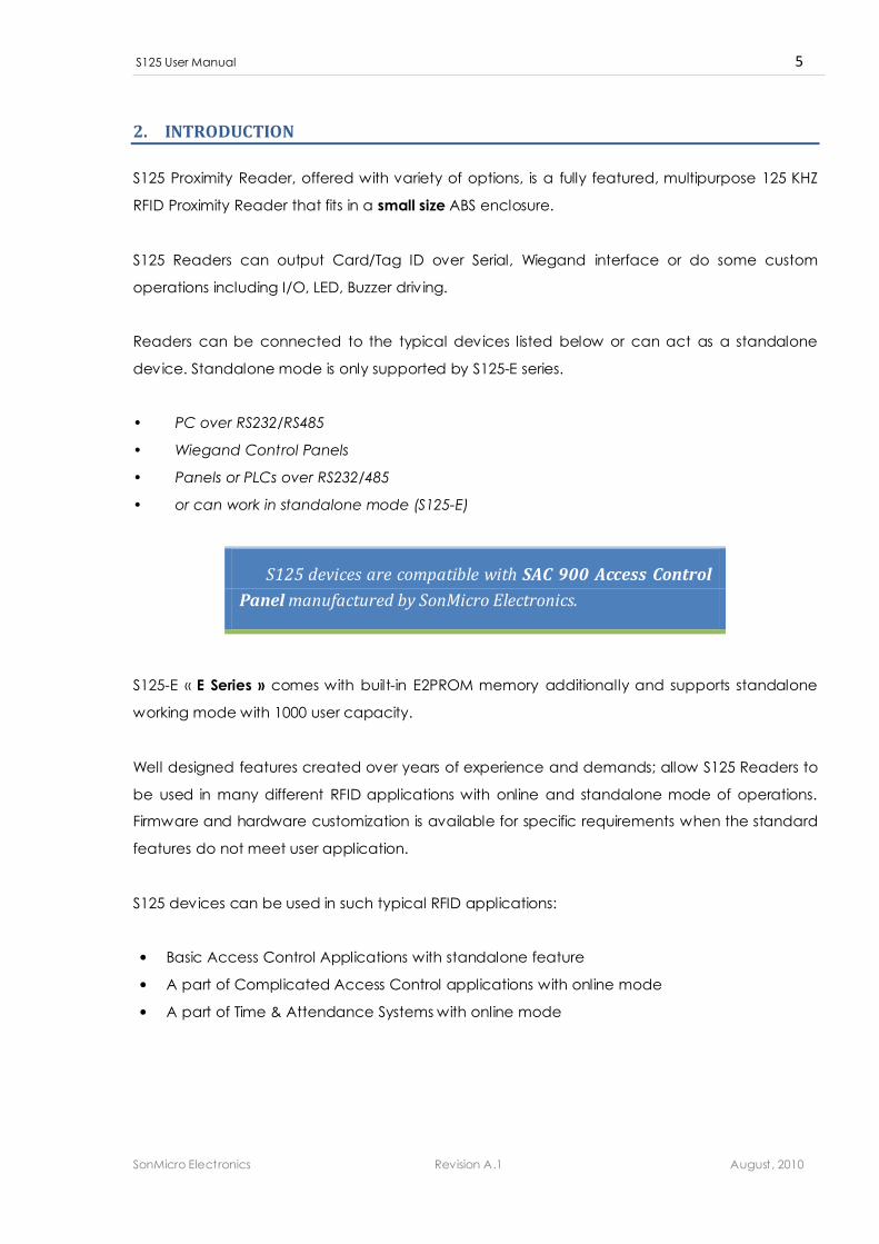
2. INTRODUCTION
S125 Proximity Reader, offered with variety of options, is a fully featured, multipurpose 125 KHZ
RFID Proximity Reader that fits in a small size ABS enclosure.
S125 Readers can output Card/Tag ID over Serial, Wiegand interface or do some custom
operations including I/O, LED, Buzzer driv ing.
Readers can be connected to the typical devices listed below or can act as a standalone
device. Standalone mode is only supported by S125-E series.
• PC over RS232/RS485
• Wiegand Control Panels
• Panels or PLCs over RS232/485
• or can work in standalone mode (S125-E)
S125 devices are compatible with SAC 900 Access Control
Panel manufactured by SonMicro Electronics.
S125-E « E Series » comes with built-in E2PROM memory additionally and supports standalone
working mode with 1000 user capacity.
Well designed features created over years of experience and demands; allow S125 Readers to
be used in many different RFID applications with online and standalone mode of operations.
Firmware and hardware customization is available for specific requirements when the standard
features do not meet user application.
S125 devices can be used in such typical RFID applications:
• Basic Access Control Applications with standalone feature
• A part of Complicated Access Control applications with online mode
• A part of Time & Attendance Systems with online mode
S125 User Manual 6
SonMicro Electronics Revision A.1 August, 2010
STANDALONE MODE
In Standalone mode when a Card is entered into the RF Field, the Card ID (5 Byte for EM410X) is
searched in built-in EEPROM memory. If it is a defined user then S125 Reader can trigger the
built-in relay, output the Card ID thru RS232/485 channel and/or Wiegand Interface and/or
simply do some custom operations without need of any external controller.
Standalone feature does not necessarily require an external controller device to be
connected. A defined Master Card can be used to teach and store User Cards or delete them
from the built-in EEPROM memory. User Card data can also be stored or deleted by using S125
Configuration software tool.
Standalone feature allows « Quick Runs » and it can be
connected to elevators, electrical doors, barriers, or any such
device that require the user granted access in minutes
without requiring any computer peripheral device.
S125-E Readers with standalone feature still supports the standard operations and can be
controlled by an external device if required.
NOTIFICATION
Standalone feature comes only with S125-E « E Series ». E denotes “EEPROM” memory.
(RTC – Real Time Clock) Time logging is not supported by any of S125 devices.
S125 User Manual 7
SonMicro Electronics Revision A.1 August, 2010
ONLINE MODE
In Online Mode, similar to the Standalone Mode, Card data sent thru RS232/485 channel
and/or Wiegand Interface and/or some custom I/O operation can be performed when a Card
is read.
The difference between the Online and Standalone mode is; Online Mode does not use built-in
EEPROM memory and the decision or the control is left to external controller such as PC or
Control Panel.
Online Mode is appropriate for complicated access control or identification systems such as
Time & Attendance applications where data is collected online by S125 devices and the
control or logging is performed by the external device such as PC or Control Panel.
If the user has no intention to use the standalone feature (built-in e2prom memory) then the
basic model of S125 devices can be used. Please notice that basic models do not include
E2PROM memory in the hardware and moreover they cannot be firmware upgraded to the “E
series” model later on.
EXTERNAL DEVICE CONTROL & SDK
All series of S125 devices can be controlled by external devices over RS232/485 by the given
Command Set. Command Set is explained in S125 Communication Protocol document. If
custom software is required to be developed, an ActiveX Control is also available and comes
within SDK – Software Development Kit, for easy software development or integration to existing
software. ActiveX Control can be used in popular Windows OS development environments
such as Delphi, Visual Studio etc. Please see SDK Document for details how to use the S125
ActiveX control.
CUSTOMIZATION
All series of S125 Readers are firmware upgrade-able. Custom firmware and hardware
requirements can be serviced upon request. Firmware updates can include a new feature, or
different behavior. Hardware I/O can be changed as well. For example, if Wiegand is not used,
two of the wiegand data outputs can be converted to 5V I/O. Special wiring or connector
requirements can also be met.
NOTIFICATION
Please notice that, basic S125 devices cannot be upgraded to « E Series » later on.
S125 User Manual 8
SonMicro Electronics Revision A.1 August, 2010
3. S125 CONFIGURATION & DEMONSTRATION SOFTWARE
S125 Configuration Software can be used to configure S125 device settings, modify E2PROM
content (store & delete users) evaluate and test the product quickly thru com port. USB-To-
RS232 or USB-To-RS485 converters can be used without any problems. For RS485 connection,
proper S125 model should be used with « -485 » suffix. (See Ordering Guide)
S125 Configuration Software is designed to be work with the S125 ActiveX Control which is also
a part of SDK. ActiveX Control will be installed and registered to your PC automatically, during
the setup process. For software developers, thus there is no need to register ActiveX control
again unless there is new version of ActiveX Control is available.
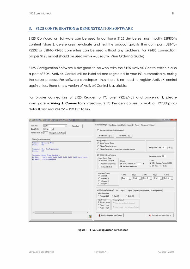
For proper connections of S125 Reader to PC over RS232/485 and powering it, please
investigate « Wiring & Connections » Section. S125 Readers comes to work at 19200bps as
default and requires 9V – 12V DC to run.
Figure 1 – S125 Configuration Screenshot
S125 User Manual 9
SonMicro Electronics Revision A.1 August, 2010
BASIC COMMUNICATION SETTINGS
S125 devices come with RS232 and RS485 options. Same serial protocol is used for both
interfaces. Baud rates of 9600, 19200, 38400, 57600 and 115200bps are supported.
• Default serial configuration is 19200bps, 1 Stop Bit, No Parity.
• Default node address is 0x01. (For RS232 Connection)
Readers can be given node address for connecting multiple S125 devices on the same RS485
line. Node address can be anywhere between 1 – 255 where node address 1 is a special
address and all devices reply to commands sent to the node address 0x01. If RS232 is going to
be used, communicating node can be adjusted to 0x01. Otherwise please see below warning.
WARNING
If RS485 is going to be used, avoid giving node address “1” to the Readers and also make sure
each device on the same RS485 line have different node address between 2 and 255.
If a firmware upgrade is necessary, it is recommended to connect the Reader directly to PC
over RS232. If RS485 is preferred then other Readers must be powered off and only the target
Reader stayed powered on the line.
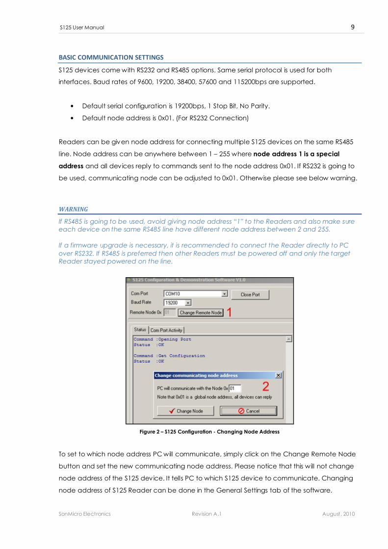
Figure 2 – S125 Configuration - Changing Node Address
To set to which node address PC will communicate, simply click on the Change Remote Node
button and set the new communicating node address. Please notice that this will not change
node address of the S125 device. It tells PC to which S125 device to communicate. Changing
node address of S125 Reader can be done in the General Settings tab of the software.
S125 User Manual 10
SonMicro Electronics Revision A.1 August, 2010
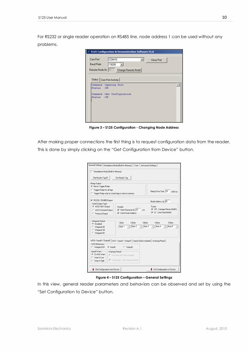
For RS232 or single reader operation on RS485 line, node address 1 can be used without any
problems.
Figure 3 – S125 Configuration - Changing Node Address
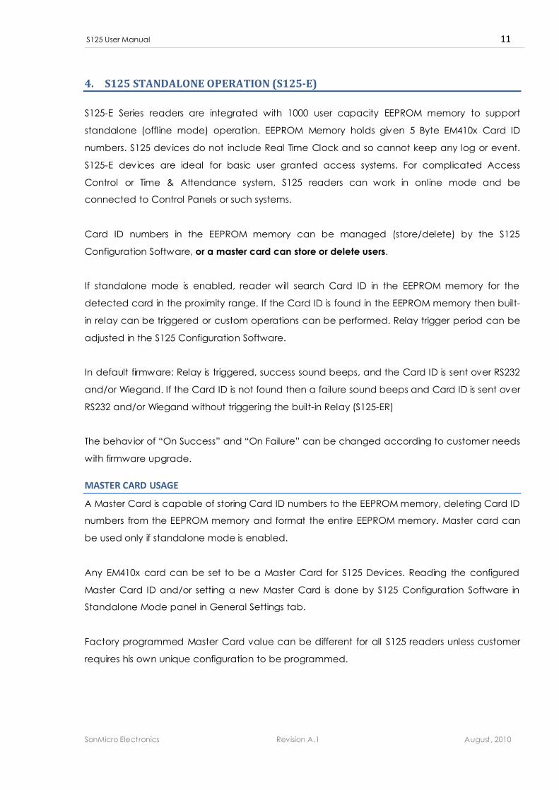
After making proper connections the first thing is to request configuration data from the reader.
This is done by simply clicking on the “Get Configuration from Device” button.
Figure 4 – S125 Configuration – General Settings
In this v iew, general reader parameters and behaviors can be observed and set by using the
“Set Configuration to Device” button.
S125 User Manual 11
SonMicro Electronics Revision A.1 August, 2010
4. S125 STANDALONE OPERATION (S125-E)
S125-E Series readers are integrated with 1000 user capacity EEPROM memory to support
standalone (offline mode) operation. EEPROM Memory holds given 5 Byte EM410x Card ID
numbers. S125 devices do not include Real Time Clock and so cannot keep any log or event.
S125-E devices are ideal for basic user granted access systems. For complicated Access
Control or Time & Attendance system, S125 readers can work in online mode and be
connected to Control Panels or such systems.
Card ID numbers in the EEPROM memory can be managed (store/delete) by the S125
Configuration Software, or a master card can store or delete users.
If standalone mode is enabled, reader will search Card ID in the EEPROM memory for the
detected card in the proximity range. If the Card ID is found in the EEPROM memory then built-
in relay can be triggered or custom operations can be performed. Relay trigger period can be
adjusted in the S125 Configuration Software.
In default firmware: Relay is triggered, success sound beeps, and the Card ID is sent over RS232
and/or Wiegand. If the Card ID is not found then a failure sound beeps and Card ID is sent over
RS232 and/or Wiegand without triggering the built-in Relay (S125-ER)
The behavior of “On Success” and “On Failure” can be changed according to customer needs
with firmware upgrade.
MASTER CARD USAGE
A Master Card is capable of storing Card ID numbers to the EEPROM memory, deleting Card ID
numbers from the EEPROM memory and format the entire EEPROM memory. Master card can
be used only if standalone mode is enabled.
Any EM410x card can be set to be a Master Card for S125 Devices. Reading the configured
Master Card ID and/or setting a new Master Card is done by S125 Configuration Software in
Standalone Mode panel in General Settings tab.
Factory programmed Master Card value can be different for all S125 readers unless customer
requires his own unique configuration to be programmed.
S125 User Manual 12
SonMicro Electronics Revision A.1 August, 2010
When the Master Card is detected a sequence of six “beeps” sounds and reader will wait for a
few seconds for the second card to store to or delete from EEPROM memory. If there is no any
card is detected in this period, teach/delete mode will end with a short single buzzer beep.
If the second card, just shown after Master Card, not in the EEPROM memory then it will be
stored to the EEPROM memory and access will be granted for this card. Buzzer will generate
two short beeps indicating the operation is successful and the Card ID is stored successfully.
If the second card was previously stored in the EEPROM memory then it will be deleted from the
EEPROM memory and access will be denied for this card. Buzzer will beep one time for a longer
period after the card is deleted from the EEPROM memory.
In Summary, any EM410x Card just shown to the Reader
after a Master Card will store the Card ID if it was not in
EEPROM memory, or will be deleted from the EEPROM memory
if it was previously stored.
Another function of the Master Card is to format, delete all Card ID numbers from, the EEPROM
memory. This is done simply by keep pressing the button on the reader and at the same time
showing the Master card to the reader. Buzzer will generate four longer beeps while formatting
the EEPROM memory and Reader will reset itself after the operation is completed.
S125 User Manual 13
SonMicro Electronics Revision A.1 August, 2010
5. S125 SERIAL COMMUNICATION
S125 Readers come with either RS232 or RS485 option. It has built-in serial protocol and this
protocol is used to control or configure the reader. In many cases there may be no necessary
to know or use the protocol, as once the S125 Reader is configured thru the Configuration
Software or the user configuration data is requested to be programmed in the factory, it can
just output Card ID with industry most demanded options thru serial channel and this is most
time adequate for the desired systems. But for systems involve external control such as to drive
built-in relay, or generate buzzer sounds, or to detect input states then the simple given
commands can be used to do these operations. For Command & Response details please
investigate the S125 Communication Protocol document also reference S125 Configuration
Software.
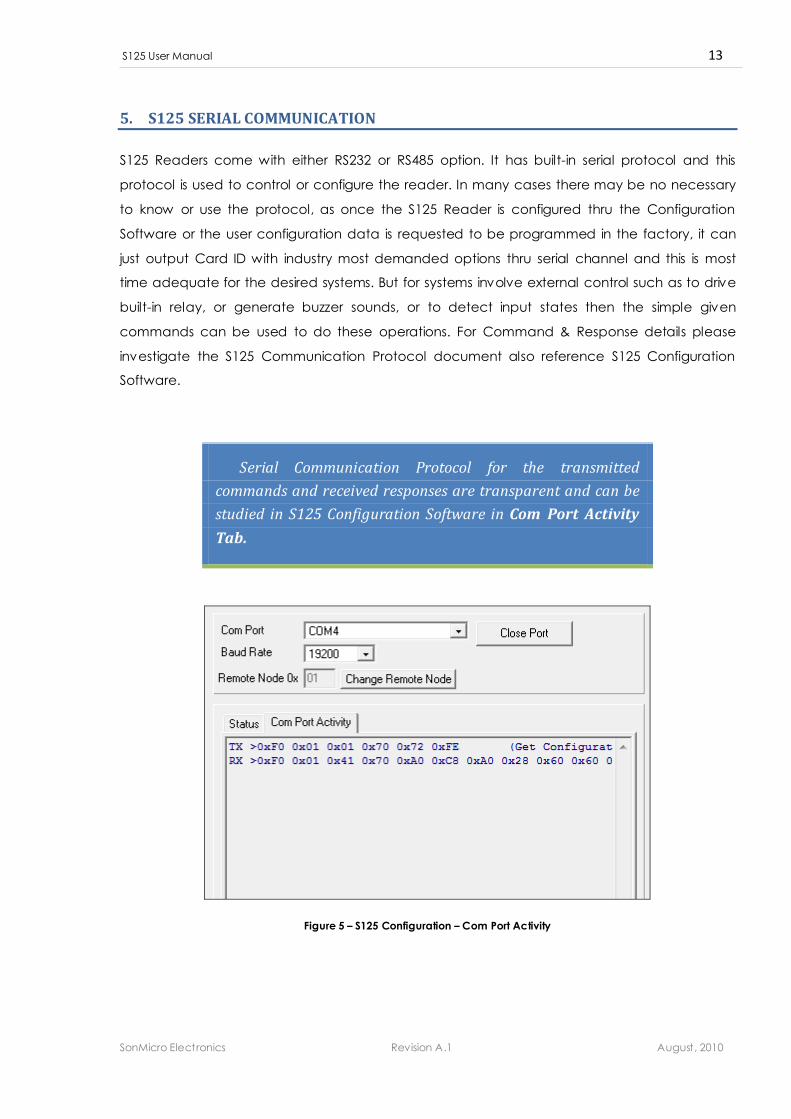
Serial Communication Protocol for the transmitted
commands and received responses are transparent and can be
studied in S125 Configuration Software in Com Port Activity
Tab.
Figure 5 – S125 Configuration – Com Port Activity
S125 User Manual 14
SonMicro Electronics Revision A.1 August, 2010
When a Card is detected in the proximity range its ID number can be send thru serial channel
with the following options or can be disabled.
Please remember that EM410x has 5 Byte unique identification number. These 5 byte ID can be
retrieved in different methods as explained below:
ASCII HEX OUPUT:
5 Byte ID is converted to ASCII characters and send as 10 digits.
For example if Card ID is consist of 5 Byte ID [0x0F 0x10 0x11 0x12 0x13] then it will be send as
“0F10111213” 10 digit as ASCII characters.
ASCII DECIMAL OUPUT:
5 Byte ID is converted to decimal representation and then send as 13 digit ASCII characters.
For example if 5 Byte ID is [0x0F 0x10 0x11 0x12 0x13] then its decimal representation
“0064694063635” will be sent.
In some cases, some old designs use last 3 bytes or 4 bytes of ID number to convert to decimal.
In this case, a firmware upgrade can be requested.
PROTOCOL OUTPUT:
5 Byte ID is send with S125 Communication protocol. Protocol includes header, data length,
data and the checksum.
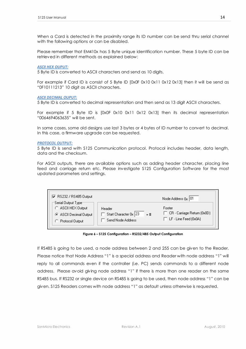
For ASCII outputs, there are available options such as adding header character, placing line
feed and carriage return etc. Please investigate S125 Configuration Software for the most
updated parameters and settings.
Figure 6 – S125 Configuration – RS232/485 Output Configuration
If RS485 is going to be used, a node address between 2 and 255 can be given to the Reader.
Please notice that Node Address “1” is a special address and Reader with node address “1” will
reply to all commands even if the controller (i.e. PC) sends commands to a different node
address. Please avoid giving node address “1” if there is more than one reader on the same
RS485 bus. If RS232 or single device on RS485 is going to be used, then node address “1” can be
given. S125 Readers comes with node address “1” as default unless otherwise is requested.
S125 User Manual 15
SonMicro Electronics Revision A.1 August, 2010
6. S125 WIEGAND OUTPUT
S125 devices support Wiegand output with flexible parametric options. Wiegand type i.e. 26
bits, 34 bits and 42 bits can be chosen and wiegand data bytes can be configured in S125
Configuration Software.
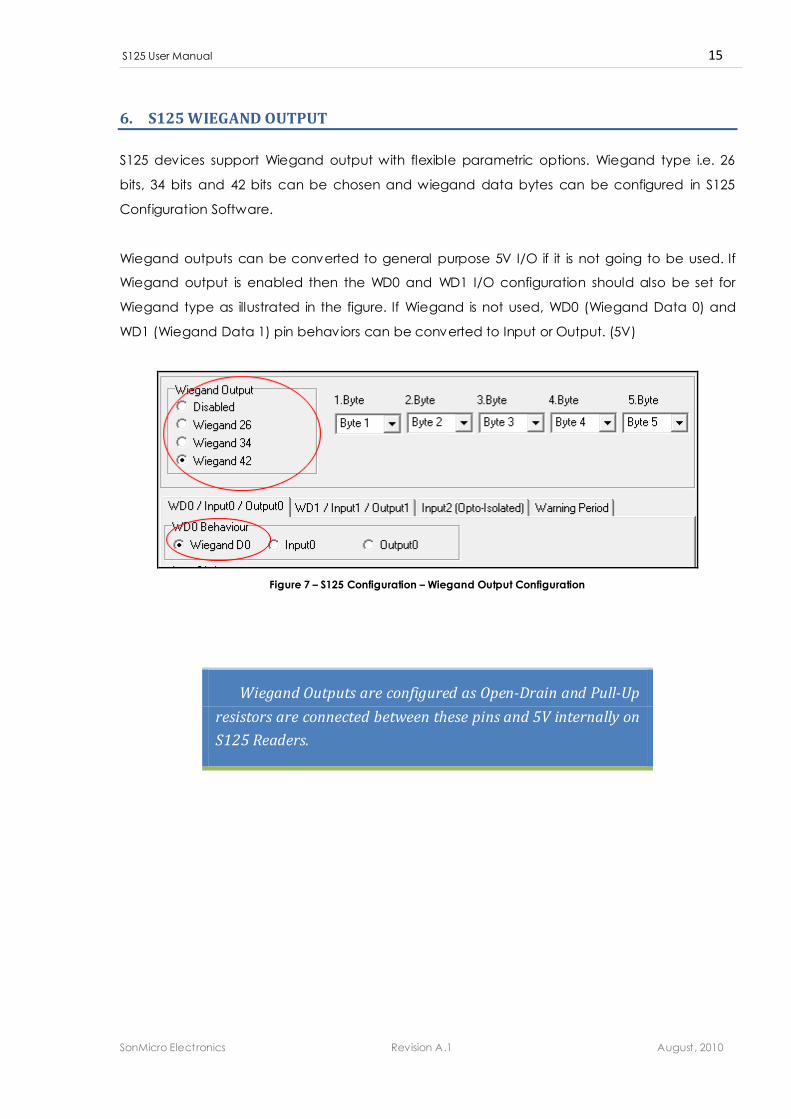
Wiegand outputs can be converted to general purpose 5V I/O if it is not going to be used. If
Wiegand output is enabled then the WD0 and WD1 I/O configuration should also be set for
Wiegand type as illustrated in the figure. If Wiegand is not used, WD0 (Wiegand Data 0) and
WD1 (Wiegand Data 1) pin behaviors can be converted to Input or Output. (5V)
Figure 7 – S125 Configuration – Wiegand Output Configuration
Wiegand Outputs are configured as Open-Drain and Pull-Up
resistors are connected between these pins and 5V internally on
S125 Readers.
S125 User Manual 16
SonMicro Electronics Revision A.1 August, 2010
7. S125 INPUT & OUTPUTS
S125 device has
- 1x Opto isolated Input (INPUT2)
- 1x Relay output.
- If Wiegand output is not used, WD0 and WD1 can be converted to 5V tolerant Input or
Output
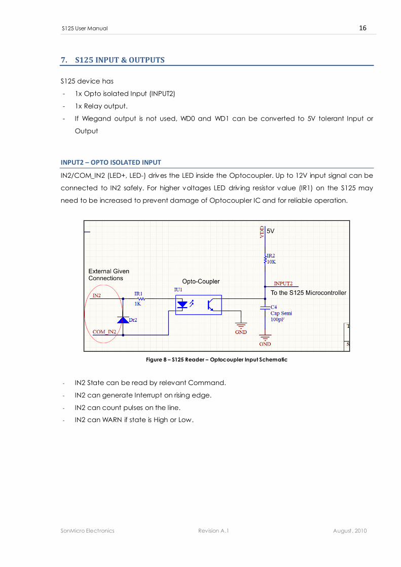
INPUT2 – OPTO ISOLATED INPUT
IN2/COM_IN2 (LED+, LED-) drives the LED inside the Optocoupler. Up to 12V input signal can be
connected to IN2 safely. For higher voltages LED driv ing resistor value (IR1) on the S125 may
need to be increased to prevent damage of Optocoupler IC and for reliable operation.
Figure 8 – S125 Reader – Optocoupler Input Schematic
- IN2 State can be read by relevant Command.
- IN2 can generate Interrupt on rising edge.
- IN2 can count pulses on the line.
- IN2 can WARN if state is High or Low.

S125 User Manual 17
SonMicro Electronics Revision A.1 August, 2010
PULSE COUNT FEATURE
Input2 state can be read by relevant command or it can
generate interrupt on rising edge. Moreover S125 can count
pulses on this line. Counted pulse numbers send over RS232 and
custom operations can be done automatically by S125 Readers
according to the pulse count. Pulse count feature is unique in
industry and served only by SonMicro and allows doing
different operations with just a single wire.
Each High Pulse should not exceed 50 milliseconds for
reliable detection.
In default firmware for one pulse count buzzer beeps one time, for two pulse counts buzzer
beeps two times, for three pulse count buzzer beeps three times just for illustration purpose.
Actions can be changed and re-defined according to customer needs such as driv ing Red
LED, Green LED, and Buzzer etc.
Up to 6 pulses can be detected reliably and custom operations can be done according to
pulse count upon customer request.
INPUT STATE WARNING FEATURE
Input pins on S125 devices can warn (beep buzzer) and
report over RS232 if states are High or Low. Warning period
and the delay to warn is parametric and can be set by S125
Configuration Software. Warning feature can be used to warn
users to keep the door closed or can be used for different
purposes.
S125 User Manual 18
SonMicro Electronics Revision A.1 August, 2010
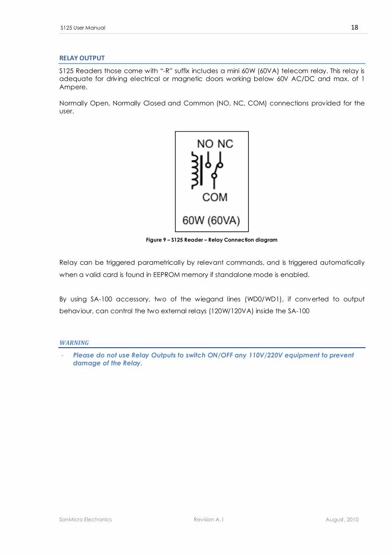
RELAY OUTPUT
S125 Readers those come with “-R” suffix includes a mini 60W (60VA) telecom relay. This relay is
adequate for driv ing electrical or magnetic doors working below 60V AC/DC and max. of 1
Ampere.
Normally Open, Normally Closed and Common (NO, NC, COM) connections provided for the
user.
Figure 9 – S125 Reader – Relay Connection diagram
Relay can be triggered parametrically by relevant commands, and is triggered automatically
when a valid card is found in EEPROM memory if standalone mode is enabled.
By using SA-100 accessory, two of the wiegand lines (WD0/WD1), if converted to output
behaviour, can control the two external relays (120W/120VA) inside the SA-100
WARNING
- Please do not use Relay Outputs to switch ON/OFF any 110V/220V equipment to prevent
damage of the Relay.
S125 User Manual 19
SonMicro Electronics Revision A.1 August, 2010
WD0 & WD1 – 5V I/O;
If Wiegand is not used, WD0 and WD1 pins can be converted to 5V tolerant digital Input or
Outputs. WD0 & WD1 pins are Open-Drain and connected to 5V by pull-up resistors.
WD0 and WD1, if used as an input, support Warning Feature like Input2 (Opto-Coupler Input).
They do not support pulse count feature and cannot generate interrupts.
Controlling WD0 or WD1, if configured as output, and reading their states, if configured as input,
can be done with relevant commands.
If WD0 or WD1 is configured as output, they can be used to drive 120W Relays inside the SA-100
Connector Box accessory.
WARNING
- WD0 & WD1 connections should be treated as 5V Digital I/O.
- Overvoltage (More than 5V) will damage entire S125 device.
- If WD0 or WD1 is configured as output, they must not be connected to ground (Short circuit
Situation) or any other output. Thus take special care if switching from Input to Output is
necessary for the WD0 and WD1 connections.
S125 User Manual 20
SonMicro Electronics Revision A.1 August, 2010
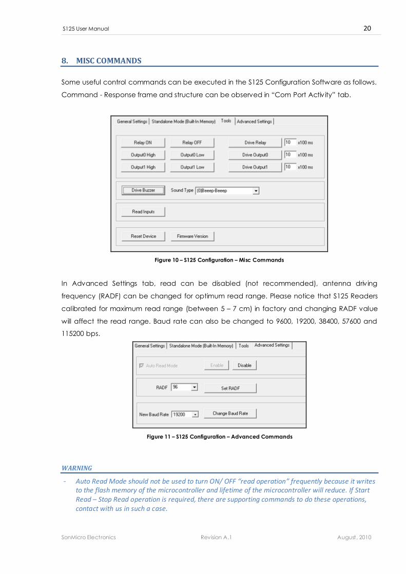
8. MISC COMMANDS
Some useful control commands can be executed in the S125 Configuration Software as follows.
Command - Response frame and structure can be observed in “Com Port Activity” tab.
Figure 10 – S125 Configuration – Misc Commands
In Advanced Settings tab, read can be disabled (not recommended), antenna driv ing
frequency (RADF) can be changed for optimum read range. Please notice that S125 Readers
calibrated for maximum read range (between 5 – 7 cm) in factory and changing RADF value
will affect the read range. Baud rate can also be changed to 9600, 19200, 38400, 57600 and
115200 bps.
Figure 11 – S125 Configuration – Advanced Commands
WARNING
- Auto Read Mode should not be used to turn ON/ OFF “read operation” frequently because it writes
to the flash memory of the microcontroller and lifetime of the microcontroller will reduce. If Start
Read – Stop Read operation is required, there are supporting commands to do these operations,
contact with us in such a case.
S125 User Manual 21
SonMicro Electronics Revision A.1 August, 2010
9. WIRING CONNECTIONS
There are two cables comes out from the S125 Reader. One is a 4 wire and the other is an 8
wire phone cable with RJ11 and RJ45 jacks. If user is only interested with RS232/485
communication and not interested with any input/output, relay or wiegand than 1x4 wire cable
is adequate to power the device and communicate over RS232/485 serial bus.
WARNING
- It is strongly recommended to reference pin numbers instead of wire colors for future compatibility.
- Please always first reference the connection pin out on the labels attached to the cables and the
reader enclosure. Remember that there is always a possibility that this document you are reading
is out of date.
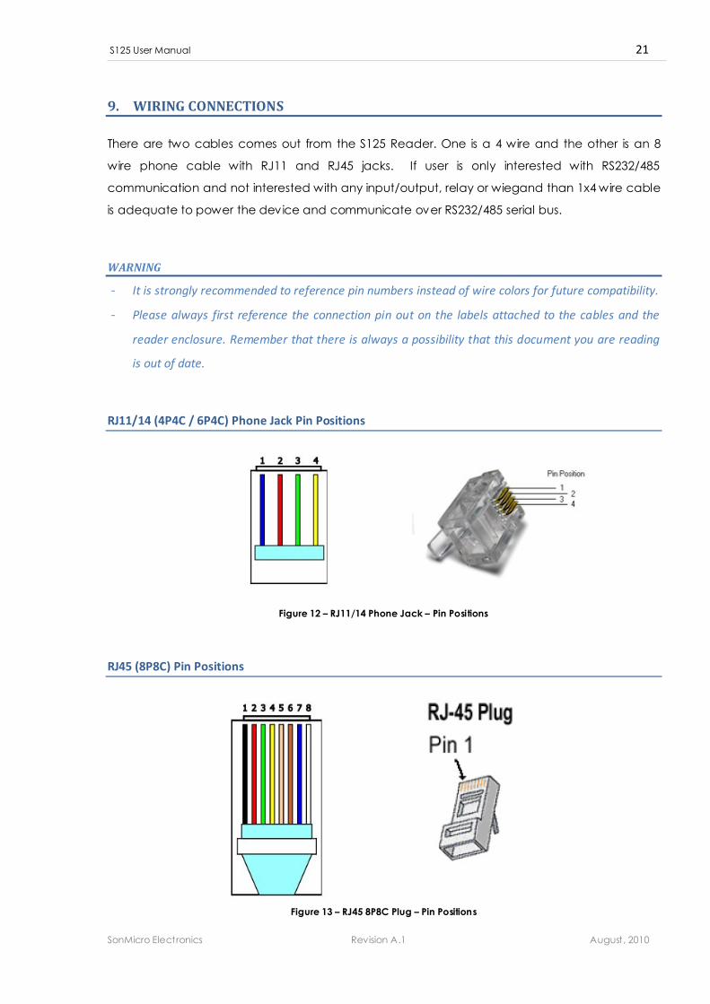
RJ11/14 (4P4C / 6P4C) Phone Jack Pin Positions
Figure 12 – RJ11/14 Phone Jack – Pin Positions
RJ45 (8P8C) Pin Positions
Figure 13 – RJ45 8P8C Plug – Pin Positions
S125 User Manual 22
SonMicro Electronics Revision A.1 August, 2010
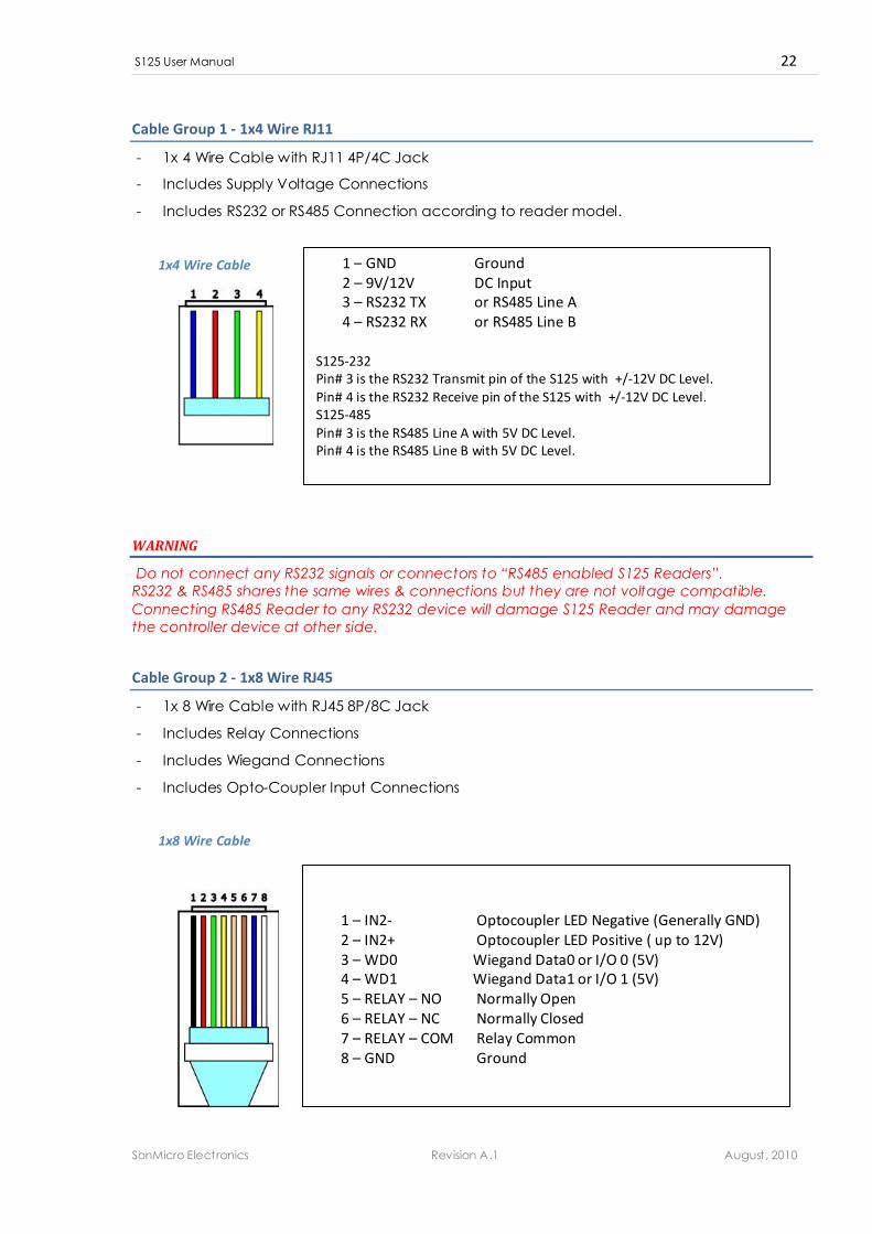
Cable Group 1 - 1x4 Wire RJ11
- 1x 4 Wire Cable with RJ11 4P/4C Jack
- Includes Supply Voltage Connections
- Includes RS232 or RS485 Connection according to reader model.
1x4 Wire Cable
WARNING
Do not connect any RS232 signals or connectors to “RS485 enabled S125 Readers”.
RS232 & RS485 shares the same wires & connections but they are not voltage compatible.
Connecting RS485 Reader to any RS232 device will damage S125 Reader and may damage
the controller device at other side.
Cable Group 2 - 1x8 Wire RJ45
- 1x 8 Wire Cable with RJ45 8P/8C Jack
- Includes Relay Connections
- Includes Wiegand Connections
- Includes Opto-Coupler Input Connections
1x8 Wire Cable
1 – IN2- Optocoupler LED Negative (Generally GND)
2 – IN2+ Optocoupler LED Positive ( up to 12V)
3 – WD0 Wiegand Data0 or I/O 0 (5V)
4 – WD1 Wiegand Data1 or I/O 1 (5V)
5 – RELAY – NO Normally Open
6 – RELAY – NC Normally Closed
7 – RELAY – COM Relay Common
8 – GND Ground
1 – GND Ground
2 – 9V/12V DC Input
3 – RS232 TX or RS485 Line A
4 – RS232 RX or RS485 Line B
S125-232
Pin# 3 is the RS232 Transmit pin of the S125 with +/-12V DC Level.
Pin# 4 is the RS232 Receive pin of the S125 with +/-12V DC Level.
S125-485
Pin# 3 is the RS485 Line A with 5V DC Level.
Pin# 4 is the RS485 Line B with 5V DC Level.
S125 User Manual 23
SonMicro Electronics Revision A.1 August, 2010
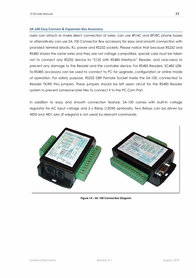
SA-100 Easy Connect & Expansion Box Accessory
Users can attach or make direct connection of wires, can use 4P/4C and 8P/8C phone boxes
or alternatively can use SA-100 Connector Box accessory for easy and smooth connection with
provided terminal blocks, RJ, power and RS232 sockets. Please notice that because RS232 and
RS485 shares the same wires and they are not voltage compatible, special care must be taken
not to connect any RS232 device to “S125 with RS485 interface” Reader, and vice-versa to
prevent any damage to the Reader and the controller device. For RS485 Readers, SC485 USB-
To-RS485 accessory can be used to connect to PC for upgrade, configuration or online mode
of operation. For safety purpose, RS232 DB9 Female Socket inside the SA-100, connected to
Reader TX/RX thru jumpers. These jumpers should be left open circuit for the RS485 Reader
system to prevent someone later tries to connect it to the PC Com Port.
In addition to easy and smooth connection feature, SA-100 comes with built-in voltage
regulator for AC input voltage and 2 x Relay (120W) optionally. Two Relays can be driven by
WD0 and WD1 pins (if wiegand is not used) by relavant commands.
Figure 14 – SA-100 Connection Diagram
S125 User Manual 24
SonMicro Electronics Revision A.1 August, 2010
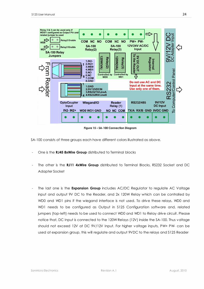
Figure 15 – SA-100 Connection Diagram
SA-100 consists of three groups each have different colors illustrated as above.
- One is the RJ45 8xWire Group distributed to Terminal blocks
- The other is the RJ11 4xWire Group distributed to Terminal Blocks, RS232 Socket and DC
Adapter Socket
- The last one is the Expansion Group includes AC/DC Regulator to regulate AC Voltage
input and output 9V DC to the Reader, and 2x 120W Relay which can be controlled by
WD0 and WD1 pins if the wiegand interface is not used. To drive these relays, WD0 and
WD1 needs to be configured as Output in S125 Configuration software and, related
jumpers (top-left) needs to be used to connect WD0 and WD1 to Relay drive circuit. Please
notice that, DC Input is connected to the 120W Relays (12V) inside the SA-100. Thus voltage
should not exceed 12V at DC 9V/12V Input. For higher voltage inputs, PW+ PW- can be
used at expansion group, this will regulate and output 9VDC to the relays and S125 Reader
S125 User Manual 25
SonMicro Electronics Revision A.1 August, 2010
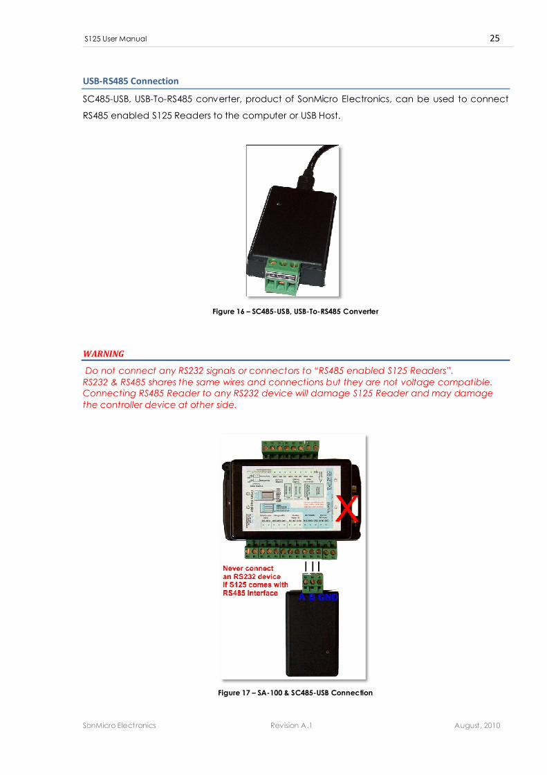
USB-RS485 Connection
SC485-USB, USB-To-RS485 converter, product of SonMicro Electronics, can be used to connect
RS485 enabled S125 Readers to the computer or USB Host.
Figure 16 – SC485-USB, USB-To-RS485 Converter
WARNING
Do not connect any RS232 signals or connectors to “RS485 enabled S125 Readers”.
RS232 & RS485 shares the same wires and connections but they are not voltage compatible.
Connecting RS485 Reader to any RS232 device will damage S125 Reader and may damage
the controller device at other side.
Figure 17 – SA-100 & SC485-USB Connection

S125 User Manual 26
SonMicro Electronics Revision A.1 August, 2010
10. ELECTRICAL CHARACTERISTICS & PERFORMANCE SPECIFICATIONS
DC CHARACTERISTICS
Description Min Typ Max Units Notes
Supply Voltage 7.5 9V 24 V DC Input Voltage
If SA-100 connector box is used
then do not use voltage higher
than 12V at DC input to prevent
damage of SA-100 Relays. Use the
AC/DC Input for voltage greater
than 12V
Current Consumption 60 80 200 mA Overall current consumption
PERFORMANCE SPECIFICATIONS
Description Min Typ Max Units Notes
Read Distance - 5 7 cm For Card Size Tags
OPERATING TEMPERATURE
Description Min Typ Max Units Notes
Ambient Temperature -20 - 55 °C
SonMicro Electronics Ltd. Cankaya M. Soguksu C.
Aslihan Ishani 2/15
Mersin, 33070
TURKEY
Phone : +90 324 237 21 28
Facsimile : +90 324 237 21 86
Email : [email protected]
Web Site : http://www.sonmicro.com