user manual - um2395 - how to use the steval-blueplug1 ... · avoid the risk of electric shocks and...
TRANSCRIPT
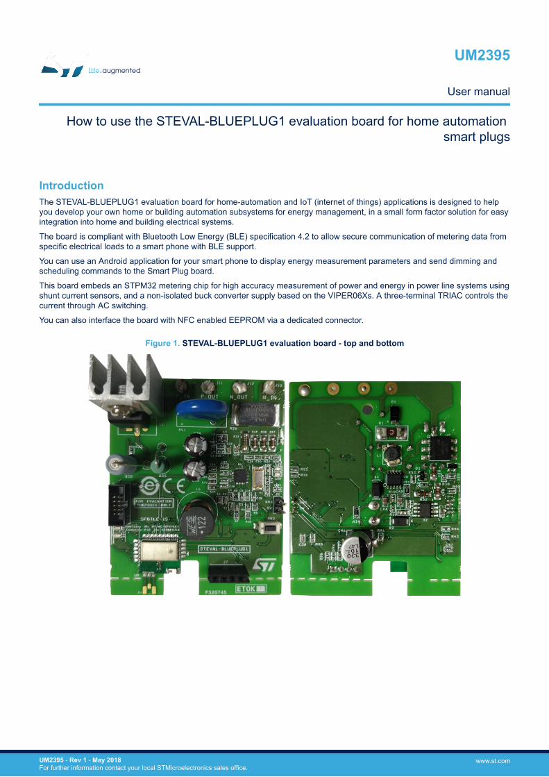
IntroductionThe STEVAL-BLUEPLUG1 evaluation board for home-automation and IoT (internet of things) applications is designed to helpyou develop your own home or building automation subsystems for energy management, in a small form factor solution for easyintegration into home and building electrical systems.
The board is compliant with Bluetooth Low Energy (BLE) specification 4.2 to allow secure communication of metering data fromspecific electrical loads to a smart phone with BLE support.
You can use an Android application for your smart phone to display energy measurement parameters and send dimming andscheduling commands to the Smart Plug board.
This board embeds an STPM32 metering chip for high accuracy measurement of power and energy in power line systems usingshunt current sensors, and a non-isolated buck converter supply based on the VIPER06Xs. A three-terminal TRIAC controls thecurrent through AC switching.
You can also interface the board with NFC enabled EEPROM via a dedicated connector.
Figure 1. STEVAL-BLUEPLUG1 evaluation board - top and bottom
How to use the STEVAL-BLUEPLUG1 evaluation board for home automation smart plugs
UM2395
User manual
UM2395 - Rev 1 - May 2018For further information contact your local STMicroelectronics sales office.
www.st.com

1 Safety information
FCC notices
Note: ST reference designs and evaluation boards are intended to help and facilitate development of products. Usinga direct copy of any of them does not waive the requirement for testing and certification of products mandated bygoverning agencies and authorities.This device compiles with part 15 of the FCC Rules. Operation is subject to the following two conditions:1. This device may not cause harmful interference2. This device must accept any interference received, including interference that may cause undesired
operation.
Electrical safety
Danger:Due to the high voltage present on the non-isolated components, special care must be taken toavoid the risk of electric shocks and burns.There are no protections against accidental human contact with high voltage components.Never touch live board components when the board is connected or immediately after the board isdisconnected, as the capacitors may still be charged.Do not connect probes to any high voltage components if the board is not isolated from the mainssupply, as this may cause damage to equipment.
1. The board must be used only by qualified persons.2. De-energize the board and all its interface outputs and electrical loads before performing any electrical or
diagnostic operations.3. Only program and debug the board with the isolated JTAG in-circuit debugger/programmer to avoid
damaging the tools.4. Use a mains insulation transformer when you perform any tests with spectrum analyzers or oscilloscopes.
Note: STMicroelectronics assumes no responsibility for accidents or injury caused by improper use of thisdevelopment tool.
Personal safety
1. Wear personal protective equipment such as latex gloves or safety glasses with side shields, or protect theEVM in an adequate lucent plastic box with interlocks from accidental touch.
UM2395Safety information
UM2395 - Rev 1 page 2/22
2 Overview
2.1 Features
• Smart Energy Meter design with wireless connectivity• BLE (Bluetooth Low Energy) v4.2 connectivity for control and metering panel: Smart-phone connectivity for
energy consumption dashboard, control of appliances• Dimming: Some loads can be controlled. For example, AC Induction fan speed, Heaters, Incandescent
lamps• Scheduling: Set the time of day for ON or OFF of the load• NFC interface: To configure the design, store the logs (connector for adapter board)• Rated voltage: 240 VAC (typ.)• Rated current: 12 A (typ.)• Power consumption of plug: 1.6 W (max.)• Instantaneous and averaged power• RMS and instantaneous voltage and current• Radio certifications:
– FCC certified: S9NSPBTLE1S– IC certified: 8976C-SPBTLE1S
• CE certified• RoHS and China RoHS compliant
2.2 Typical applications• Control and monitoring of energy parameters using BLE.• Smart metering• Home automation• Smart lighting
UM2395Overview
UM2395 - Rev 1 page 3/22
2.3 Board architecture
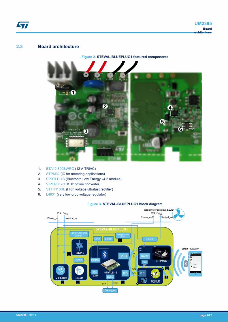
Figure 2. STEVAL-BLUEPLUG1 featured components
3
2
1
5
4
6
1. BTA12-800BWRG (12 A TRIAC)2. STPM32 (IC for metering applications)3. SPBTLE-1S (Bluetooth Low Energy v4.2 module)4. VIPER06 (30 KHz offline converter)5. STTH110RL (High voltage ultrafast rectifier)6. L4931 (very low drop voltage regulator)
Figure 3. STEVAL-BLUEPLUG1 block diagram
UART
SWD
GPIOs
Vdd I2C
STPM32
UARTTxRx
M24LR
I2CSDA
VIPER06 L4931
SWD
Debugger
OPTO
BTA12
230 VAC
Phase_in Neutral_in Phase_out Neutral_out
IIN
Zero Crossing Circuit
LEDs Switch
STEVAL-BLUEPLUG1
230 VAC
Inductive or resistive LOAD
3.3V
Vdd
3.3V
Vdd
3.3V
Voltage DividerCircuit
VIPVIN
Shunt
VIPerPLUS
SCK
ST25
IIPSmart Plug APP
STBTLE-1S SCL
o p t i o n a l
UM2395Board
architecture
UM2395 - Rev 1 page 4/22
The mains supply and loads are monitored by the STPM32 standard metering IC, while the SPBTLE-1S BluetoothLow Energy module handles data and command interfacing for the Smart Plug Android app developed for theboard, and can store data via the EEPROM connector.The 12 A TRIAC acts as a switch for the load and phase controller for dimming.The supplies for the ICs are regulated from the VIPER06 buck converter output.The board includes a manual switch to turn the load on and off, and LEDs to signal connectivity status.
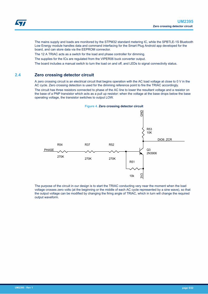
2.4 Zero crossing detector circuitA zero crossing circuit is an electrical circuit that begins operation with the AC load voltage at close to 0 V in theAC cycle. Zero crossing detection is used for the dimming reference point to fire the TRIAC accordingly.The circuit has three resistors connected to phase of the AC line to lower the resultant voltage and a resistor onthe base of a PNP transistor which acts as a pull up resistor: when the voltage at the base drops below the baseoperating voltage, the transistor switches to output LOW.
Figure 4. Zero crossing detector circuit
R54
270K
DIO6_ZCR
10K
3V3
R53
GND
PHASE
270K
2N3906
R37
R51
10k
270K
Q3R52
The purpose of the circuit in our design is to start the TRIAC conducting very near the moment when the loadvoltage crosses zero volts (at the beginning or the middle of each AC cycle represented by a sine wave), so thatthe output voltage can be modified by changing the firing angle of TRIAC, which in turn will change the requiredoutput waveform.
UM2395Zero crossing detector circuit
UM2395 - Rev 1 page 5/22
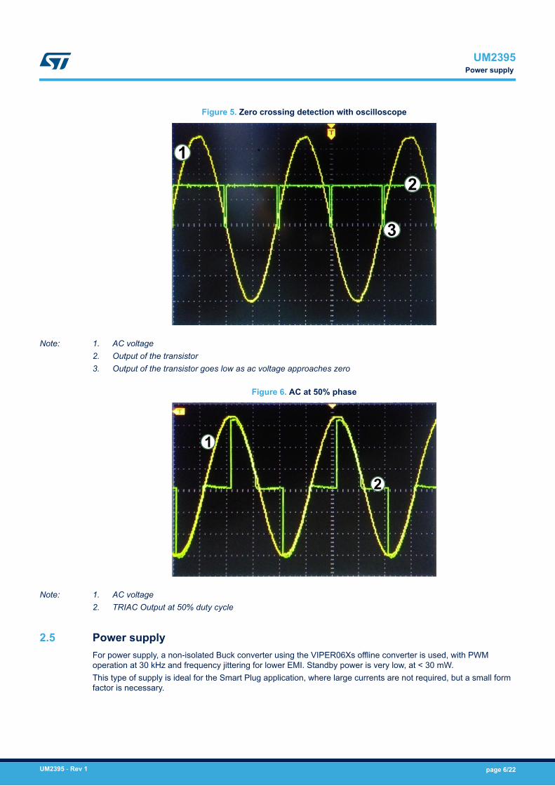
Figure 5. Zero crossing detection with oscilloscope
3
2
1
Note: 1. AC voltage2. Output of the transistor3. Output of the transistor goes low as ac voltage approaches zero
Figure 6. AC at 50% phase
2
1
Note: 1. AC voltage2. TRIAC Output at 50% duty cycle
2.5 Power supplyFor power supply, a non-isolated Buck converter using the VIPER06Xs offline converter is used, with PWMoperation at 30 kHz and frequency jittering for lower EMI. Standby power is very low, at < 30 mW.This type of supply is ideal for the Smart Plug application, where large currents are not required, but a small formfactor is necessary.
UM2395Power supply
UM2395 - Rev 1 page 6/22
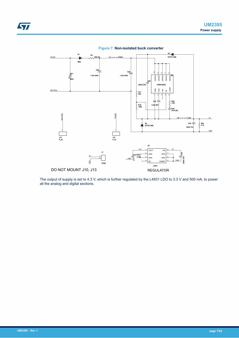
Figure 7. Non-isolated buck converter
1
RR3322
RR3344
PP__IINN
NEUT
RAL
VD
D2
DD11
GND 7JJ11
RR1111
11..55uuFF 2255VV
SSMMAA
DD22
2277nnFF,,2255vv
CC4444
LIM
3CCOONN22
CC4466
5V
CC1177
116600kk
11..55uuFF,,440000VV
LL111100EE,,11WW
GND
RR1100
MMOOVV
5V
CC1188
UU22
5
11..11mmHH
LL44993311
NN__IINN
SSTTTTHH111100RRLL
PHAS
E
GND
CO
MP
7
GN
D1
110000nn
FF,,1166
VV
INHIBIT
6GNDGND
77..55KK
22..22uuFF,,5500VV
CC4499
8822kk
3V3
333300uuff 1100vv
VVIIPPEERR 0066XXSS
JJ1100
GND
JJ1133
RRVV11
DR
AIN
10
DO NOT MOUNT J10, J13
DD44SSTTTTHH111100RRLL
NC4
11..55uuFF,,440000VV
CC4455
8CC3366
1
12
VOUT
GND2
GND3
DR
AIN
9
PHASE
NEUTRAL
FB4
5V
RR11
UU66
LL66
DR
AIN
6D
RA
IN
GNDD
RA
IN
8VIN
CC3344
220000nnFF,,2255VV
1
5
REGULATOR
55..11kk
447700uuHH
The output of supply is set to 4.3 V, which is further regulated by the L4931 LDO to 3.3 V and 500 mA, to powerall the analog and digital sections.
UM2395Power supply
UM2395 - Rev 1 page 7/22

3 Set up the board and connect with the Android app
Warning:Before performing this task, please review all the safety procedures and precautions associatedwith high voltage electrical circuits, and prepare the necessary protection equipment.
Use the procedure below to set up the board.
Step 1. On the evaluation board, connect the input mains and output load connectors.Input mains connectors:– P_IN (J10)– N_IN (J13)
Load connectors:– P_OUT (J11)– N_OUT (J12)
Figure 8. Phase (P) and neutral (N) input (IN) and output (OUT) connectors
3
2
1
5
4
6
P_IN P_OUT N_OUT N_IN
J10 J11 J12 J13
Step 2. After powering up the board, RED LED (LD3) will indicate that the board is turned ON.Step 3. Install the SmartPlug.apk Android app from the release package and launch it.
Figure 9. Smart Plug launch screen
Step 4. Search for the device on your smart phone by selecting the [Plugs found] icon.Step 5. Connect the device to the App by selecting the Smart_Plug_NRG1 device.
Once connected with the board, the BLUE LED (LD2) will blink at the frequency of 2 Hz.
UM2395Set up the board and connect
with the Android app
UM2395 - Rev 1 page 8/22
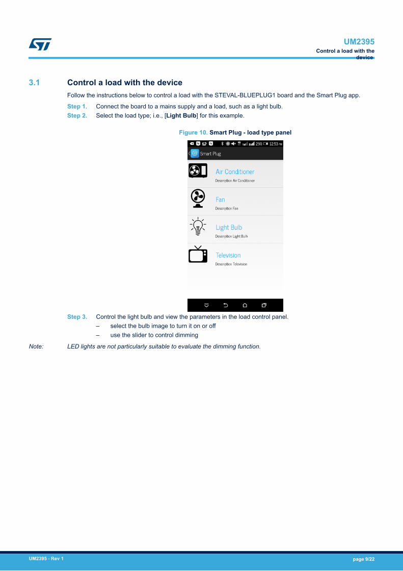
3.1 Control a load with the deviceFollow the instructions below to control a load with the STEVAL-BLUEPLUG1 board and the Smart Plug app.
Step 1. Connect the board to a mains supply and a load, such as a light bulb.Step 2. Select the load type; i.e., [Light Bulb] for this example.
Figure 10. Smart Plug - load type panel
Step 3. Control the light bulb and view the parameters in the load control panel.– select the bulb image to turn it on or off– use the slider to control dimming
Note: LED lights are not particularly suitable to evaluate the dimming function.
UM2395Control a load with the
device
UM2395 - Rev 1 page 9/22
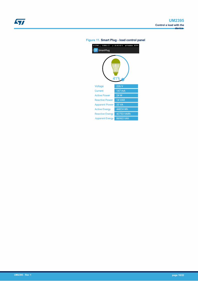
Figure 11. Smart Plug - load control panel
UM2395Control a load with the
device
UM2395 - Rev 1 page 10/22
4 State machine
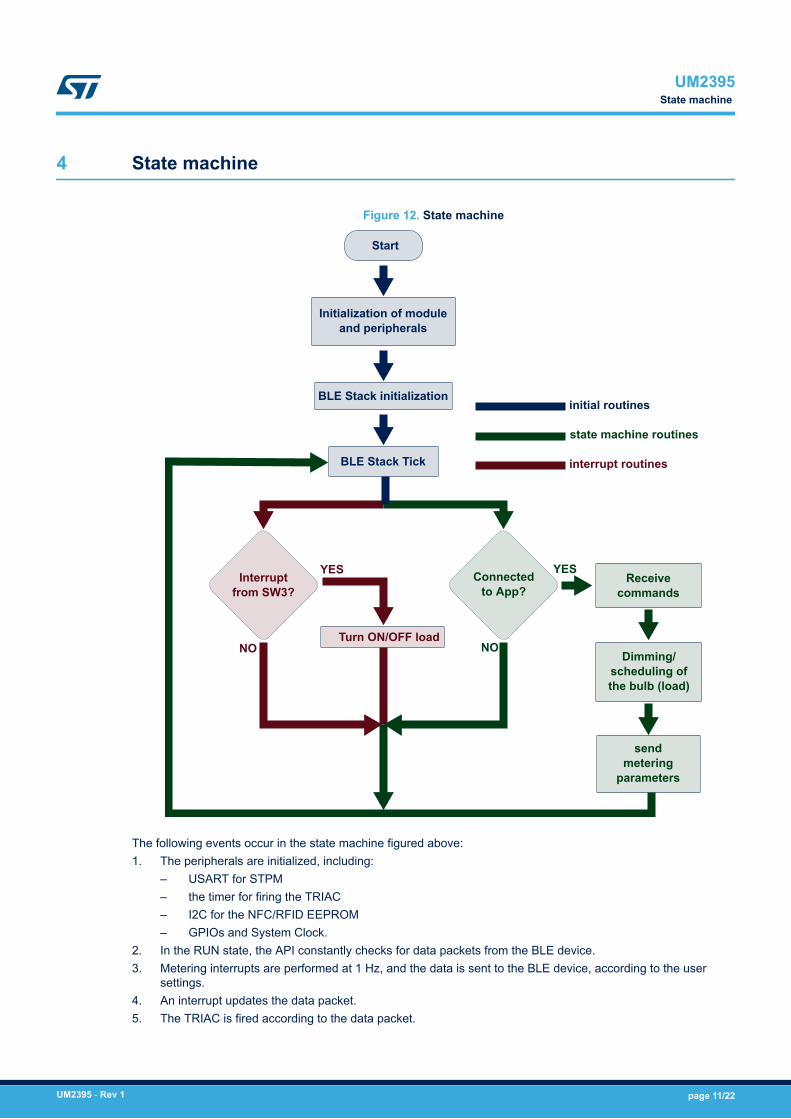
Figure 12. State machine
YES
NO
YES
NO
Start
Initialization of module and peripherals
BLE Stack initialization
BLE Stack Tick
Interruptfrom SW3?
Turn ON/OFF load
Connectedto App?
Receivecommands
Dimming/ scheduling ofthe bulb (load)
sendmetering
parameters
initial routines
state machine routines
interrupt routines
The following events occur in the state machine figured above:1. The peripherals are initialized, including:
– USART for STPM– the timer for firing the TRIAC– I2C for the NFC/RFID EEPROM– GPIOs and System Clock.
2. In the RUN state, the API constantly checks for data packets from the BLE device.3. Metering interrupts are performed at 1 Hz, and the data is sent to the BLE device, according to the user
settings.4. An interrupt updates the data packet.5. The TRIAC is fired according to the data packet.
UM2395State machine
UM2395 - Rev 1 page 11/22
5 Schematic diagrams
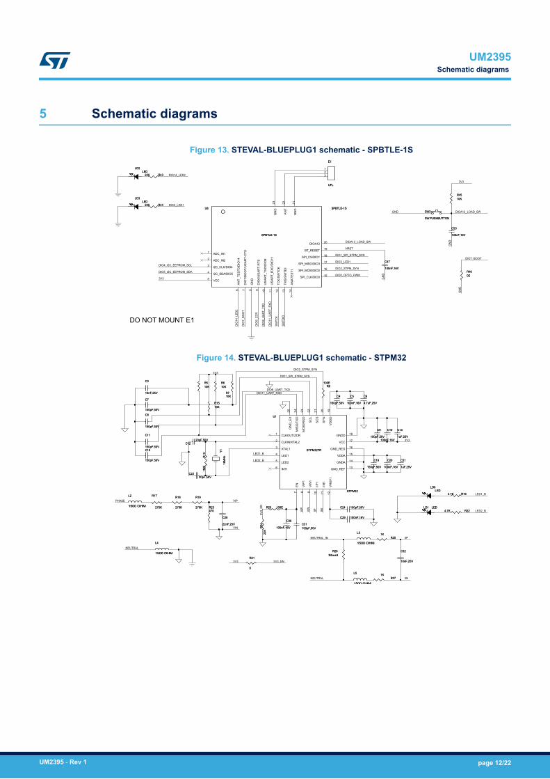
Figure 13. STEVAL-BLUEPLUG1 schematic - SPBTLE-1S
RR4444
SSWW33
DIO14_LED2
5 VCC
LLDD33
DIO5_I2C_EEPROM_SDA
3V3
CC5500
DIO1_SPI_STPM_SCS
DIO3_LED1
GND DIOA12_LOAD_SW
SPI_CS/DIO1
6110000nnFF,,1166VV
00EERR4466
SWTD
IO
123
DIO
7_BO
OT
GND
US
AR
T_R
XD
/DIO
11
DIOA12_LOAD_SW
222200
I2C_CLK/DIO4
ADC_IN2
3
SSPPBBTTLLEE--11SSA
NT_
TES
T0/D
IO14
110000nnFF,,1166VV
7
UU88
SSWW PPUUSSHHBBUUTTTTOONN
DIO
7/B
OO
T/U
SA
RT-
CTS
9
CC4477
12TC
K/S
WTC
K
1322
GN
D23
SWTC
K
DIO
11_U
ART_
RXD
4
DIO3_LED1
TMS
/SW
TDI 16SPI_MOSI/DIO2
17
RR44551100KK
DIO
6/U
SA
RT-
RTS
10
GND
1
DO NOT MOUNT E1
DIOA12
GND
NRST
DIO0_OPTO_PWM15SPI_CLK/DIO0
GN
D8
DIO7_BOOT
21
AN
T SSPPBBTTLLEE--11SS
RR4433
DIO
14_L
ED2
UUFFLL
LLEEDD
19BT_RESET
20
DIO2_STPM_SYN
3V3
DIO4_I2C_EEPROM_SCL
EE11
GN
D14
AN
ATE
ST1
DIO
8_UA
RT_T
XD
DIO
6_ZC
R
SPI_MISO/DIO3
18
222200
LLDD22LLEEDD
I2C_SDA/DIO5
US
AR
T_TX
D/D
IO8
11
ADC_IN1
2
Figure 14. STEVAL-BLUEPLUG1 schematic - STPM32
21
SC
L22
1100nnFF,,2255VV
1100KK
11550000 OOHHMM
SSTTPPMM3322TTRR
11KK
11KKRR2255
15
VIP
1
9
LLDD00
115500ppFF,,5500VV
RR1199
RR2222
RR1133 LED1_B
44..77uuFF,,2255VV
DIO2_STPM_SYN
20
SC
S
110000nnFF,,1166VV
YY11
4 LED1
23
NEUTRAL RR2277
3V3_
EN
RR88
110000nnFF,,1166VV
LLEEDD
115500ppFF,,5500VV
3V3 3V3_EN
115500ppFF,,5500VV
115500ppFF,,5500VV
LL44
CC88
2222nnFF,,2255VV
3V3DIO1_SPI_STPM_SCS
DIO11_UART_RXD
RR2266
00
44..77KK
110000nnFF,,1166VV
RR1177
2222KK
LED2_B
MO
SI/R
XD
110000nnFF,,1166VV
10
IIN1
11
VIN
1100KK
227700KK
11550000 OOHHMM
RR2200
11uuFF,,2255VV2200ppFF,,5500VV
IIN
115500ppFF,,5500VV
RR2211
IIN
115500ppFF,,5500VV
17
16
SShhuunntt
VIN
1
IIP1
CC1111 115500ppFF,,5500VV
115500ppFF,,5500VV
CLKOUT/ZCR
2
CC1144
CC2222
110000nnFF,,1166VV
RR1188
CLKIN/XTAL2
3
SSTTPPMM3322
CC66CC77
IIP
11550000 OOHHMM
11uuFF,,2255VV
VCC
IIPNEUTRAL_IN
XTAL1
GNDD 181CC1100
RR2244
CC55
CC2211
LLDD11 LLEEDD
VDDA
110000EE
13
CC1122
VD
DD
19
CC2244
8
CC3311
CC44
227700KK
2200ppFF,,5500VV
RR55
CC2200
CC3322
5
1100KK
24M
ISO
/TX
D
110000EE
RR1166
11MMEE
CC33
CC1155
NEUTRAL
VR
EF1
12
RR2233
CC3300
INT1
EN
7
1100nnFF,,2255VV
PHASE
44..77KK
UU11
3V3
CC2299
LED2
VIP
VIN
CC119914
CC2288
25G
ND
_EX
LL33
115500ppFF,,5500VV
DIO8_UART_TXD
11550000 OOHHMM
LED1_B
GND_REG
6
LL55
447700
1100KK
RR1155
LL22
RR77
227700KK
VIP
GND_REF
GNDA
RR66
SY
N
CC99
1166MM
HHzz
LED2_B
UM2395Schematic diagrams
UM2395 - Rev 1 page 12/22

Figure 15. STEVAL-BLUEPLUG1 schematic - Viper power supply
1
RR3322
RR3344
PP__IINN
NEUT
RAL
VD
D2
DD11
GND 7JJ11
RR1111
11..55uuFF 2255VV
SSMMAA
DD22
2277nnFF,,2255vv
CC4444
LIM
3CCOONN22
CC4466
5V
CC1177
116600kk
11..55uuFF,,440000VV
LL111100EE,,11WW
GND
RR1100
MMOOVV
5V
CC1188
UU22
5
11..11mmHH
LL44993311
NN__IINN
SSTTTTHH111100RRLL
PHAS
E
GND
CO
MP
7
GN
D1
110000nn
FF,,1166
VV
INHIBIT
6GNDGND
77..55KK
22..22uuFF,,5500VV
CC4499
8822kk
3V3
333300uuff 1100vv
VVIIPPEERR 0066XXSS
JJ1100
GND
JJ1133
RRVV11
DR
AIN
10
DO NOT MOUNT J10, J13
DD44SSTTTTHH111100RRLL
NC4
11..55uuFF,,440000VV
CC4455
8CC3366
1
12
VOUT
GND2
GND3
DR
AIN
9
PHASE
NEUTRAL
FB4
5V
RR11
UU66
LL66
DR
AIN
6D
RA
IN
GNDD
RA
IN
8VIN
CC3344
220000nnFF,,2255VV
1
5
REGULATOR
55..11kk
447700uuHH
Figure 16. STEVAL-BLUEPLUG1 schematic - Snubberless TRIAC section
R33220
2
PHASE
1J11
J12
3
2STR12151
6
1
N_OUT
R35
333300
1
R28
1
NEUTRAL_IN
100P_OUT
33V3
DIO0_OPTO_PWM
2
BTA12-800BWRG
RR33991100KK
Q2
DO NOT MOUNT J11, J12
2
MOC3020 4
Q1U5
R38
11KK
Figure 17. STEVAL-BLUEPLUG1 schematic - ZCD
R54
270K
DIO6_ZCR
10K
3V3
R53
GND
PHASE
270K
2N3906
R37
R51
10k
270K
Q3R52
UM2395Schematic diagrams
UM2395 - Rev 1 page 13/22
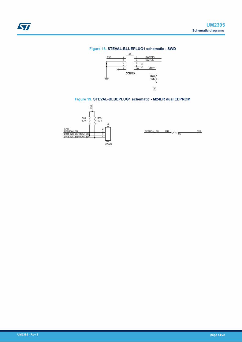
Figure 18. STEVAL-BLUEPLUG1 schematic - SWD
3V3 SWTDIO
8
4 SWTCK6
107
RR44001100KK
3V3
JJ662
5
1
CCOONN1100AA
9 NRST
3
Figure 19. STEVAL-BLUEPLUG1 schematic - M24LR dual EEPROM
EEPROM_EN 3V3
DIO5_I2C_EEPROM_SDA
EEPROM_ENGND
3V3
DIO4_I2C_EEPROM_SCL
J7
CONN
1234
R604.7K
R420E
R554.7K
UM2395Schematic diagrams
UM2395 - Rev 1 page 14/22

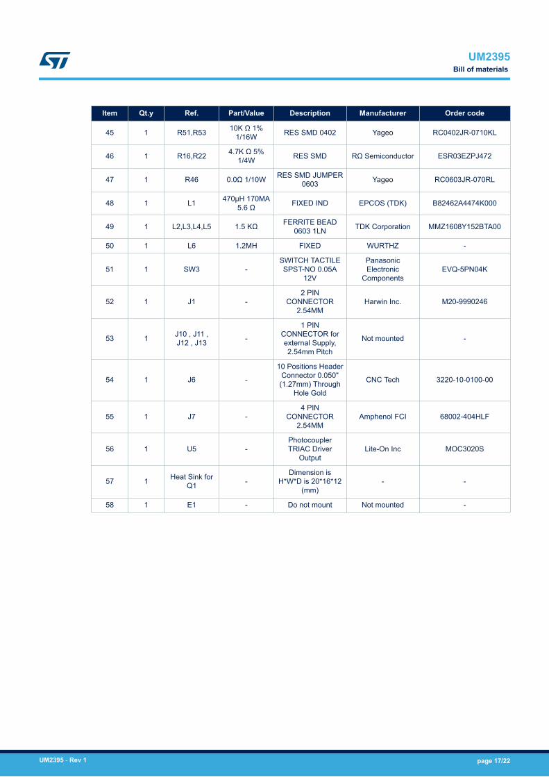
6 Bill of materials
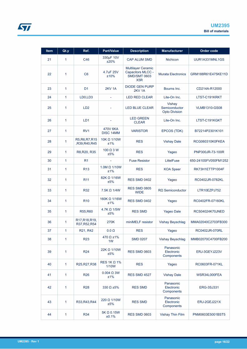
Table 1. STEVAL-BLUEPLUG1 bill of materials
Item Qt.y Ref. Part/Value Description Manufacturer Order code
1 1 U1 -
ASSP for meteringapplications with upto four independent
24-bit 2nd ordersigma-delta ADC
ST STPM32TR
2 1 U2 - Voltage Regulator ST L4931CD33-TR
3 1 U6 -Energy saving 4W
high voltageconverter
ST VIPER06XS
4 1 U8 -
Very low powermodule for
Bluetooth Smartv4.2
ST SPBTLE-1S
5 1 D2,D4 -High voltage
ultrafast rectifierdiode
ST STTH110RL
6 1 Q1 -12 A standard and
Snubberless™TRIACS
ST BTA12-800BWRG
7 1 Q2 40 V, 0.8 A NPN bipolartransistor ST 2STR1215
8 1 Q3 - PNP bipolartransistor ST 2STR2160
9 1 Y1 - CRYSTAL 16.000MHZ 20pF ECS Inc. ECS-160-20-23A-EN-TR
10 1 C3,C32 10nF 25V CAP CER Kemet C0603C103F3GACTU
11 1C4,C7,C8,C9,C11,C15,C19,
C24,C31
150pF 50V±5% CAP CER Taiyo Yuden UMK105CG151JV-F
12 1C5,C10,C18,C20,C29,C30,C
47,C50100nF 16V CAP CER Yageo CC0402KRX7R7BB104
13 1 C14,C21 1µF 25V CAP CER X5R0603 Taiyo Yuden TMK107BJ105KA-T
14 1 C34,C36 1.5µF 400V AluminumCapacitors Radial Nichicon ULD2G1R5MED1TD
15 1 C49 0.22µF 25V CAP CER X7R0805
Samsung Electro-Mechanics America,
Inc.CL21B224KAFNNNG
16 1 C12,C22 20pF 50V CAP CER Murata ElectronicsNorth America GRM1555C1H200JA01D
17 1 C17 2.2µF 35V CAP CER X5R0402 TDK Corporation C1005X5R1V225K050BC
18 1 C44 1.5µF 25V CAP CER X7R0805 TDK Corporation C2012X7R1E155M125A
C
19 1 C45 0.027µF 25V CAP CER X8R0805 Kemet C0805C273K3HACTU
20 1 C28 22nF 25V CAP CER Kemet C0603C223J3RACTU
UM2395Bill of materials
UM2395 - Rev 1 page 15/22
Item Qt.y Ref. Part/Value Description Manufacturer Order code
21 1 C46 330µF 10V±20% CAP ALUM SMD Nichicon UUR1A331MNL1GS
22 1 C6 4.7uF 25V±10%
Multilayer CeramicCapacitors MLCC -
SMD/SMT 0603X5R
Murata Electronics GRM188R61E475KE11D
23 1 D1 2KV 1A DIODE GEN PURP2KV 1A Bourns Inc. CD214A-R12000
24 1 LD0,LD3 - LED RED CLEAR Lite-On Inc. LTST-C191KRKT
25 1 LD2 - LED BLUE CLEARVishay
SemiconductorOpto Division
VLMB1310-GS08
26 1 LD1 - LED GREENCLEAR Lite-On Inc. LTST-C191KGKT
27 1 RV1 470V 6KADISC 14MM VARISTOR EPCOS (TDK) B72214P2301K101
28 1 R5,R6,R7,R15,R39,R40,R45
10K Ω 1/10W±1% RES Vishay Dale RCG060310K0FKEA
29 1 R8,R20, R35 100 Ω 3 W±5% RES Yageo PNP300JR-73-100R
30 1 R1 - Fuse Resistor LittelFuse 650-2410SFV050FM1252
31 1 R13 1.0M Ω 1/10W±1% RES KOA Speer RK73H1ETTP1004F
32 1 R11 82K Ω 1/16W±5% RES SMD 0402 Yageo RC0402JR-0782KL
33 1 R32 7.5K Ω 1/4W RES SMD 0805WIDE RΩ Semiconductor LTR10EZPJ752
34 1 R10 160K Ω 1/16W±1% RES SMD 0402 Yageo RC0402FR-07160KL
35 1 R55,R60 4.7K Ω 1/5W±5% RES SMD Yageo Dale RCS04024K70JNED
36 1 R17,R18,R19,R37,R52,R54 270K miniMELF resistor Vishay Beyschlag MMA02040C2703FB300
37 1 R21, R42 0.0 Ω RES Yageo RC0402JR-070RL
38 1 R23 470 Ω ±1%1W SMD 0207 Vishay Beyschlag MMB02070C4700FB200
39 1 R24 22K Ω 1/10W±5% RES SMD 0603
PanasonicElectronic
ComponentsERJ-3GEYJ223V
40 1 R25,R27,R38 RES 1K Ω 1%1/10W RES Yageo RC0603FR-071KL
41 1 R26 0.004 Ω 3W±1% RES SMD 4527 Vishay Dale WSR34L000FEA
42 1 R28 330 Ω ±5% RES SMDPanasonicElectronic
ComponentsERG-3SJ331
43 1 R33,R43,R44 220 Ω 1/10W±5% RES SMD
PanasonicElectronic
ComponentsERJ-2GEJ221X
44 1 R34 5K Ω 0.15W±0.1% RES SMD 0603 Vishay Thin Film PNM0603E5001BST5
UM2395Bill of materials
UM2395 - Rev 1 page 16/22
Item Qt.y Ref. Part/Value Description Manufacturer Order code
45 1 R51,R53 10K Ω 1%1/16W RES SMD 0402 Yageo RC0402JR-0710KL
46 1 R16,R22 4.7K Ω 5%1/4W RES SMD RΩ Semiconductor ESR03EZPJ472
47 1 R46 0.0Ω 1/10W RES SMD JUMPER0603 Yageo RC0603JR-070RL
48 1 L1 470µH 170MA5.6 Ω FIXED IND EPCOS (TDK) B82462A4474K000
49 1 L2,L3,L4,L5 1.5 KΩ FERRITE BEAD0603 1LN TDK Corporation MMZ1608Y152BTA00
50 1 L6 1.2MH FIXED WURTHZ -
51 1 SW3 -SWITCH TACTILESPST-NO 0.05A
12V
PanasonicElectronic
ComponentsEVQ-5PN04K
52 1 J1 -2 PIN
CONNECTOR2.54MM
Harwin Inc. M20-9990246
53 1 J10 , J11 ,J12 , J13 -
1 PINCONNECTOR forexternal Supply,2.54mm Pitch
Not mounted -
54 1 J6 -
10 Positions HeaderConnector 0.050"(1.27mm) Through
Hole Gold
CNC Tech 3220-10-0100-00
55 1 J7 -4 PIN
CONNECTOR2.54MM
Amphenol FCI 68002-404HLF
56 1 U5 -PhotocouplerTRIAC Driver
OutputLite-On Inc MOC3020S
57 1 Heat Sink forQ1 -
Dimension isH*W*D is 20*16*12
(mm)- -
58 1 E1 - Do not mount Not mounted -
UM2395Bill of materials
UM2395 - Rev 1 page 17/22

Revision history
Table 2. Document revision history
Date Version Changes
02-May-2018 1 Initial release.
UM2395
UM2395 - Rev 1 page 18/22
Contents
1 Safety information . . . . . . . . . . . . . . . . . . . . . . . . . . . . . . . . . . . . . . . . . . . . . . . . . . . . . . . . . . . . . . . . .2
2 Overview . . . . . . . . . . . . . . . . . . . . . . . . . . . . . . . . . . . . . . . . . . . . . . . . . . . . . . . . . . . . . . . . . . . . . . . . . .3
2.1 Features . . . . . . . . . . . . . . . . . . . . . . . . . . . . . . . . . . . . . . . . . . . . . . . . . . . . . . . . . . . . . . . . . . . . . . 3
2.2 Typical applications. . . . . . . . . . . . . . . . . . . . . . . . . . . . . . . . . . . . . . . . . . . . . . . . . . . . . . . . . . . . . 3
2.3 Board architecture. . . . . . . . . . . . . . . . . . . . . . . . . . . . . . . . . . . . . . . . . . . . . . . . . . . . . . . . . . . . . . 3
2.4 Zero crossing detector circuit. . . . . . . . . . . . . . . . . . . . . . . . . . . . . . . . . . . . . . . . . . . . . . . . . . . . . 5
2.5 Power supply . . . . . . . . . . . . . . . . . . . . . . . . . . . . . . . . . . . . . . . . . . . . . . . . . . . . . . . . . . . . . . . . . . 6
3 Set up the board and connect with the Android app . . . . . . . . . . . . . . . . . . . . . . . . . . . . . . . .8
3.1 Control a load with the device . . . . . . . . . . . . . . . . . . . . . . . . . . . . . . . . . . . . . . . . . . . . . . . . . . . . 8
4 State machine . . . . . . . . . . . . . . . . . . . . . . . . . . . . . . . . . . . . . . . . . . . . . . . . . . . . . . . . . . . . . . . . . . . .11
5 Schematic diagrams . . . . . . . . . . . . . . . . . . . . . . . . . . . . . . . . . . . . . . . . . . . . . . . . . . . . . . . . . . . . . .12
6 Bill of materials . . . . . . . . . . . . . . . . . . . . . . . . . . . . . . . . . . . . . . . . . . . . . . . . . . . . . . . . . . . . . . . . . . .15
Revision history . . . . . . . . . . . . . . . . . . . . . . . . . . . . . . . . . . . . . . . . . . . . . . . . . . . . . . . . . . . . . . . . . . . . . . .18
UM2395Contents
UM2395 - Rev 1 page 19/22
List of figuresFigure 1. STEVAL-BLUEPLUG1 evaluation board - top and bottom . . . . . . . . . . . . . . . . . . . . . . . . . . . . . . . . . . . . . . 1Figure 2. STEVAL-BLUEPLUG1 featured components . . . . . . . . . . . . . . . . . . . . . . . . . . . . . . . . . . . . . . . . . . . . . . . 4Figure 3. STEVAL-BLUEPLUG1 block diagram . . . . . . . . . . . . . . . . . . . . . . . . . . . . . . . . . . . . . . . . . . . . . . . . . . . . 4Figure 4. Zero crossing detector circuit . . . . . . . . . . . . . . . . . . . . . . . . . . . . . . . . . . . . . . . . . . . . . . . . . . . . . . . . . . 5Figure 5. Zero crossing detection with oscilloscope. . . . . . . . . . . . . . . . . . . . . . . . . . . . . . . . . . . . . . . . . . . . . . . . . . 6Figure 6. AC at 50% phase . . . . . . . . . . . . . . . . . . . . . . . . . . . . . . . . . . . . . . . . . . . . . . . . . . . . . . . . . . . . . . . . . . 6Figure 7. Non-isolated buck converter . . . . . . . . . . . . . . . . . . . . . . . . . . . . . . . . . . . . . . . . . . . . . . . . . . . . . . . . . . . 7Figure 8. Phase (P) and neutral (N) input (IN) and output (OUT) connectors . . . . . . . . . . . . . . . . . . . . . . . . . . . . . . . . 8Figure 9. Smart Plug launch screen . . . . . . . . . . . . . . . . . . . . . . . . . . . . . . . . . . . . . . . . . . . . . . . . . . . . . . . . . . . . 8Figure 10. Smart Plug - load type panel . . . . . . . . . . . . . . . . . . . . . . . . . . . . . . . . . . . . . . . . . . . . . . . . . . . . . . . . . . 9Figure 11. Smart Plug - load control panel . . . . . . . . . . . . . . . . . . . . . . . . . . . . . . . . . . . . . . . . . . . . . . . . . . . . . . . . 10Figure 12. State machine . . . . . . . . . . . . . . . . . . . . . . . . . . . . . . . . . . . . . . . . . . . . . . . . . . . . . . . . . . . . . . . . . . . 11Figure 13. STEVAL-BLUEPLUG1 schematic - SPBTLE-1S . . . . . . . . . . . . . . . . . . . . . . . . . . . . . . . . . . . . . . . . . . . . 12Figure 14. STEVAL-BLUEPLUG1 schematic - STPM32 . . . . . . . . . . . . . . . . . . . . . . . . . . . . . . . . . . . . . . . . . . . . . . 12Figure 15. STEVAL-BLUEPLUG1 schematic - Viper power supply . . . . . . . . . . . . . . . . . . . . . . . . . . . . . . . . . . . . . . . 13Figure 16. STEVAL-BLUEPLUG1 schematic - Snubberless TRIAC section . . . . . . . . . . . . . . . . . . . . . . . . . . . . . . . . . 13Figure 17. STEVAL-BLUEPLUG1 schematic - ZCD . . . . . . . . . . . . . . . . . . . . . . . . . . . . . . . . . . . . . . . . . . . . . . . . . 13Figure 18. STEVAL-BLUEPLUG1 schematic - SWD . . . . . . . . . . . . . . . . . . . . . . . . . . . . . . . . . . . . . . . . . . . . . . . . . 14Figure 19. STEVAL-BLUEPLUG1 schematic - M24LR dual EEPROM . . . . . . . . . . . . . . . . . . . . . . . . . . . . . . . . . . . . . 14
UM2395List of figures
UM2395 - Rev 1 page 20/22
List of tablesTable 1. STEVAL-BLUEPLUG1 bill of materials . . . . . . . . . . . . . . . . . . . . . . . . . . . . . . . . . . . . . . . . . . . . . . . . . . . . 15Table 2. Document revision history . . . . . . . . . . . . . . . . . . . . . . . . . . . . . . . . . . . . . . . . . . . . . . . . . . . . . . . . . . . . . 18
UM2395List of tables
UM2395 - Rev 1 page 21/22

IMPORTANT NOTICE – PLEASE READ CAREFULLY
STMicroelectronics NV and its subsidiaries (“ST”) reserve the right to make changes, corrections, enhancements, modifications, and improvements to STproducts and/or to this document at any time without notice. Purchasers should obtain the latest relevant information on ST products before placing orders. STproducts are sold pursuant to ST’s terms and conditions of sale in place at the time of order acknowledgement.
Purchasers are solely responsible for the choice, selection, and use of ST products and ST assumes no liability for application assistance or the design ofPurchasers’ products.
No license, express or implied, to any intellectual property right is granted by ST herein.
Resale of ST products with provisions different from the information set forth herein shall void any warranty granted by ST for such product.
ST and the ST logo are trademarks of ST. All other product or service names are the property of their respective owners.
Information in this document supersedes and replaces information previously supplied in any prior versions of this document.
© 2018 STMicroelectronics – All rights reserved
UM2395
UM2395 - Rev 1 page 22/22