user manual flir ir spot thermometers manual flir ir spot thermometers tg54 ir spot thermometer tg56...
TRANSCRIPT
USER MANUAL
FLIR IR Spot Thermometers
TG54 IR Spot Thermometer
TG56 IR Spot Thermometer with Thermocouple
FLIR TG54_TG56 User Manual 2 Document Identifier: TG54_TG56‐en‐US_AA
Table of Contents 1 DISCLAIMER 4
1.1 Copyright 4
1.2 Quality Assurance 4
1.3 Documentation 4
1.4 Disposal of Electronic Waste 4
2 SAFETY 5
2.1 International Safety Symbols 5
2.2 Cautions 5
3 INTRODUCTION 6
3.1 Key Features 6
4 DESCRIPTIONS 7
4.1 Rear Description 7
4.2 Front Description 7
4.3 Top Description 7
4.4 Main Display Description 8
4.5 Display Icon Descriptions 9
4.6 Control Buttons and Trigger Descriptions 10
5 OPERATION 11
5.1 Power the meter 11
5.2 Taking Measurements 11
5.3 Distance‐To‐Spot Ratio 12
5.4 Using the High and Low Alarm 13
5.5 Display Mode Options 13
5.6 Using the Type K Thermometer (TG56 only) 15
6 PROGRAMMING MENU 16
6.1 Programming Menu Overview 16
6.2 Programming Menu Editing 16
FLIR TG54_TG56 User Manual 3 Document Identifier: TG54_TG56‐en‐US_AA
6.2.1 Setting the Display Modes 18
6.2.2 Setting the Emissivity 18
6.2.3 Programming High and Low Alarms 19
6.2.4 Setting the Laser Pointer ON or OFF 19
6.2.5 Setting the Temperature Units oC/oF 19
6.2.6 Setting the AUTO Power OFF (APO) Timer 20
6.2.7 Viewing the Help Screen 20
6.2.8 Viewing the Info Screen 20
7 MAINTENANCE 21
7.1 Battery Replacement 21
7.2 Calibration 21
7.3 Cleaning 21
8 SPECIFICATIONS 22
8.1 General Specifications 22
8.2 Environmental Specifications 22
8.3 IR Thermometer Specifications 23
8.4 Laser Specifications 23
8.5 Thermocouple Specifications 23
9 APPENDICES 24
9.1 Emissivity Factors for Common Materials 24
9.2 Infrared Energy and IR Thermometer Theory 25
10 CUSTOMER SUPPORT 26
11 WARRANTY INFORMATION 27
11.1 FLIR Test & Measurement 5 year Limited Warranty 27
FLIR TG54_TG56 User Manual 4 Document Identifier: TG54_TG56‐en‐US_AA
1 Disclaimer
1.1 Copyright
© 2015, FLIR Systems, Inc. All rights reserved worldwide. No parts of the software including source
code may be reproduced, transmitted, transcribed or translated into any language or computer
language in any form or by any means, electronic, magnetic, optical, manual or otherwise, without
the prior written permission of FLIR Systems.
The documentation must not, in whole or part, be copied, photocopied, reproduced, translated or
transmitted to any electronic medium or machine readable form without prior consent, in writing,
from FLIR Systems.
Names and marks appearing on the products herein are either registered trademarks or
trademarks of FLIR Systems and/or its subsidiaries. All other trademarks, trade names or company
names referenced herein are used for identification only and are the property of their respective
owners.
1.2 Quality Assurance The Quality Management System under which these products are developed and manufactured
has been certified in accordance with the ISO 9001 standard.
FLIR Systems is committed to a policy of continuous development; therefore we reserve the right
to make changes and improvements on any of the products without prior notice.
1.3 Documentation
To access the latest manuals and notifications, go to the Download tab at: http://support.flir.com.
It only takes a few minutes to register online. In the download area you will also find the latest
releases of manuals for our other products, as well as manuals for our historical and obsolete
products.
1.4 Disposal of Electronic Waste
As with most electronic products, this equipment must be disposed of in an
environmentally friendly way, and in accordance with existing regulations for electronic
waste. Please contact your FLIR Systems representative for more details.
FLIR TG54_TG56 User Manual 5 Document Identifier: TG54_TG56‐en‐US_AA
2 Safety
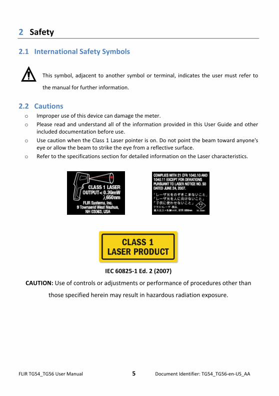
2.1 International Safety Symbols
This symbol, adjacent to another symbol or terminal, indicates the user must refer to
the manual for further information.
2.2 Cautions o Improper use of this device can damage the meter.
o Please read and understand all of the information provided in this User Guide and other included documentation before use.
o Use caution when the Class 1 Laser pointer is on. Do not point the beam toward anyone's eye or allow the beam to strike the eye from a reflective surface.
o Refer to the specifications section for detailed information on the Laser characteristics.
IEC 60825‐1 Ed. 2 (2007)
CAUTION: Use of controls or adjustments or performance of procedures other than
those specified herein may result in hazardous radiation exposure.
FLIR TG54_TG56 User Manual 6 Document Identifier: TG54_TG56‐en‐US_AA
3 Introduction
Thank you for selecting the FLIR IR Thermometer. This device is shipped fully tested and
calibrated and, with proper use, will provide years of reliable service. Please visit our
support website www.flir.com/testwarranty to register the device, to check for the
latest version of this User Guide, to view product updates, and to contact Customer
Support.
3.1 Key Features
Intuitive and fully programmable IR Spot Thermometer
Quick boot time, one second approximately
Bright, easy‐to‐read graphical color display
Laser Pointer for targeting accuracy
30:1 (TG56) and 24:1 (TG54) Distance to Spot ratio
Easy‐to‐use programming settings menu
Quick emissivity selection with four presets and a custom mode. Preset emissivity
icons include visual surface ‘texture’ examples for convenience.
Color‐coded High and Low Alarm functions
MIN, MAX, Average, Delta, and 3‐reading display modes
Type K thermocouple thermometer input on the TG56
Programmable Auto Power OFF feature
Rugged industrial design
Lanyard on handle
Portable and battery operated
Tool‐less battery compartment (twist‐off end cap)
FLIR TG54_TG56 User Manual 7 Document Identifier: TG54_TG56‐en‐US_AA
4 Descriptions
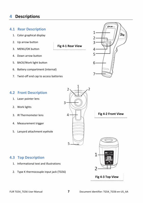
4.1 Rear Description
1. Color graphical display
2. Up arrow button
3. MENU/OK button
4. Down arrow button
5. BACK/Work light button
6. Battery compartment (internal)
7. Twist‐off end cap to access batteries
4.2 Front Description
1. Laser pointer lens
2. Work lights
3. IR Thermometer lens
4. Measurement trigger
5. Lanyard attachment eyehole
4.3 Top Description
1. Informational text and illustrations
2. Type K thermocouple input jack (TG56)
Fig 4‐1 Rear View
Fig 4‐2 Front View
Fig 4‐3 Top View
1
23
45
6
7
12 2
3
4
5
1
2
FLIR TG54_TG56 User Manual 8 Document Identifier: TG54_TG56‐en‐US_AA
1 2 3 4 5 6
7
8910
11
121314
111213
7
8
9
10
1 2 3 4 5 6
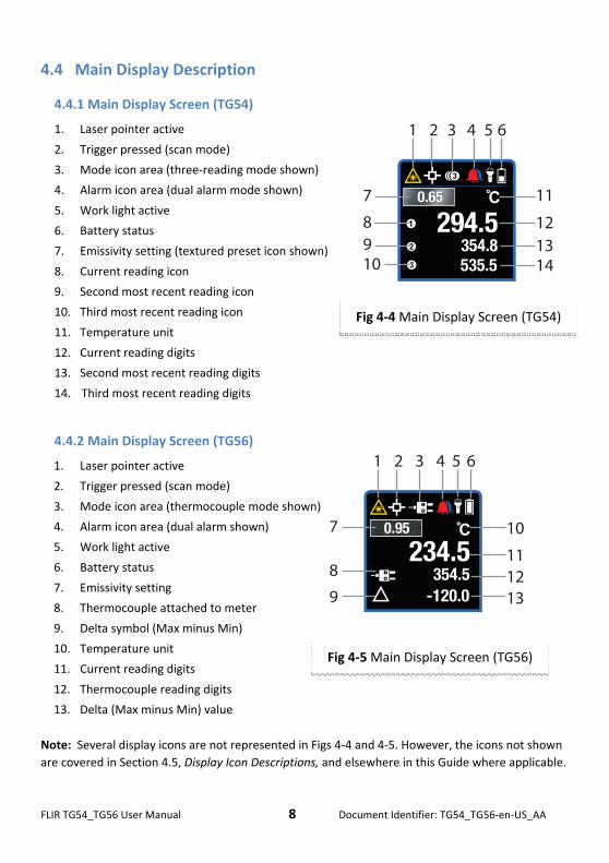
4.4 Main Display Description
4.4.1 Main Display Screen (TG54)
1. Laser pointer active
2. Trigger pressed (scan mode)
3. Mode icon area (three‐reading mode shown)
4. Alarm icon area (dual alarm mode shown)
5. Work light active
6. Battery status
7. Emissivity setting (textured preset icon shown)
8. Current reading icon
9. Second most recent reading icon
10. Third most recent reading icon
11. Temperature unit
12. Current reading digits
13. Second most recent reading digits
14. Third most recent reading digits
4.4.2 Main Display Screen (TG56)
1. Laser pointer active
2. Trigger pressed (scan mode)
3. Mode icon area (thermocouple mode shown)
4. Alarm icon area (dual alarm shown)
5. Work light active
6. Battery status
7. Emissivity setting
8. Thermocouple attached to meter
9. Delta symbol (Max minus Min)
10. Temperature unit
11. Current reading digits
12. Thermocouple reading digits
13. Delta (Max minus Min) value
Note: Several display icons are not represented in Figs 4‐4 and 4‐5. However, the icons not shown
are covered in Section 4.5, Display Icon Descriptions, and elsewhere in this Guide where applicable.
Fig 4‐4 Main Display Screen (TG54)
Fig 4‐5 Main Display Screen (TG56)
FLIR TG54_TG56 User Manual 9 Document Identifier: TG54_TG56‐en‐US_AA
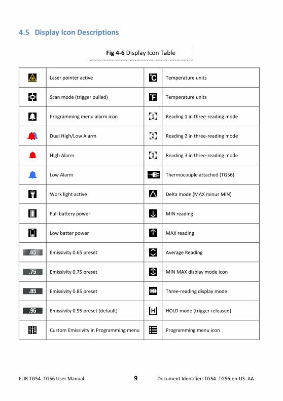
4.5 Display Icon Descriptions
Laser pointer active Temperature units
Scan mode (trigger pulled) Temperature units
Programming menu alarm icon Reading 1 in three‐reading mode
Dual High/Low Alarm Reading 2 in three‐reading mode
High Alarm Reading 3 in three‐reading mode
Low Alarm Thermocouple attached (TG56)
Work light active Delta mode (MAX minus MIN)
Full battery power MIN reading
Low batter power MAX reading
Emissivity 0.65 preset Average Reading
Emissivity 0.75 preset MIN MAX display mode icon
Emissivity 0.85 preset Three‐reading display mode
Emissivity 0.95 preset (default) HOLD mode (trigger released)
Custom Emissivity in Programming menu Programming menu icon
Fig 4‐6 Display Icon Table
FLIR TG54_TG56 User Manual 10 Document Identifier: TG54_TG56‐en‐US_AA
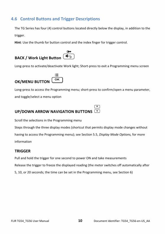
4.6 Control Buttons and Trigger Descriptions
The TG Series has four (4) control buttons located directly below the display, in addition to the
trigger.
Hint: Use the thumb for button control and the index finger for trigger control.
BACK / Work Light Button
Long‐press to activate/deactivate Work light; Short‐press to exit a Programming menu screen
OK/MENU BUTTON
Long‐press to access the Programming menu; short‐press to confirm/open a menu parameter,
and toggle/select a menu option
UP/DOWN ARROW NAVIGATION BUTTONS
Scroll the selections in the Programming menu
Steps through the three display modes (shortcut that permits display mode changes without
having to access the Programming menu); see Section 5.5, Display Mode Options, for more
information
TRIGGER
Pull and hold the trigger for one second to power ON and take measurements
Release the trigger to freeze the displayed reading (the meter switches off automatically after
5, 10, or 20 seconds; the time can be set in the Programming menu, see Section 6)
FLIR TG54_TG56 User Manual 11 Document Identifier: TG54_TG56‐en‐US_AA
5 Operation
5.1 Power the meter
1. Pull and hold the trigger for one second to switch the meter ON and begin scanning
surface temperatures.
2. The TG Series is powered by three (3) 1.5V ‘AAA’ batteries. Batteries are located in the
meter (twist off the handle cap to release the battery holder). Refer to Section 7,
Maintenance, for more detail.
3. The Battery status icon is shown on the upper right side of the display. The status icon
shows full white when 100% powered and darkens as battery power weakens. The
battery status icon appears empty (fully dark) when the batteries require changing. Note
that temperature readings displayed while the battery symbol is empty will be accurate.
Accuracy is assured up until the meter switches OFF.
4. The TG Series has a programmable APO (Auto Power OFF) feature where it automatically
shuts off after the trigger is released (after 5, 10, or 20 seconds). Please refer to Section 6,
Programming Menu, for instructions on setting the APO time.
5.2 Taking Measurements
1. Begin by pulling and holding the trigger for one second.
2. While holding the trigger, scan the surface(s) under test. Use the Laser pointer as a guide.
Notice that while the trigger is pulled the display shows the scanning icon and laser
pointer icon .
3. View the temperature reading and other information on the display while scanning. If the
measurement exceeds the published range, the display will indicate ‘OL’. Read Section
4.4, Main Display Descriptions, and Section 4.5, Display Icon Descriptions, for reference.
4. To set the temperature units (oC/oF) please refer to Section 6, Programming Menu.
5. When the trigger is released, the scanning and laser icons are replaced by the (HOLD)
icon and the displayed temperature reading is held for a programmable period of time (5,
FLIR TG54_TG56 User Manual 12 Document Identifier: TG54_TG56‐en‐US_AA
10, or 20 seconds), after which the meter switches off automatically. To set the Auto
Power OFF period please refer to Section 6, Programming Menu.
6. The laser pointer targets the measurement ‘spot’. The Laser pointer can be deactivated in
the Programming menu.
7. At this point it is important to read Section 9.2, Infrared Energy and IR Thermometer
Theory, and Section 5.3, Distance‐To‐Spot Ratio.
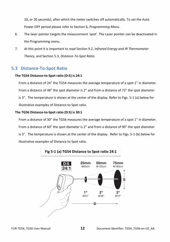
5.3 Distance‐To‐Spot Ratio
The TG54 Distance‐to‐Spot ratio (D:S) is 24:1
From a distance of 24” the TG54 measures the average temperature of a spot 1” in diameter.
From a distance of 48” the spot diameter is 2” and from a distance of 72” the spot diameter
is 3”. The temperature is shown at the center of the display. Refer to Figs. 5‐1 (a) below for
illustrative examples of Distance to Spot ratio.
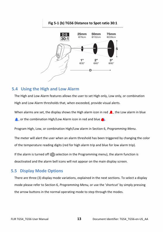
The TG56 Distance‐to‐Spot ratio (D:S) is 30:1
From a distance of 30” the TG56 measures the average temperature of a spot 1” in diameter.
From a distance of 60” the spot diameter is 2” and from a distance of 90” the spot diameter
is 3”. The temperature is shown at the center of the display. Refer to Figs. 5‐1 (b) below for
illustrative examples of Distance to Spot ratio.
Fig 5‐1 (a) TG54 Distance to Spot ratio 24:1
FLIR TG54_TG56 User Manual 13 Document Identifier: TG54_TG56‐en‐US_AA
5.4 Using the High and Low Alarm
The High and Low Alarm features allows the user to set High only, Low only, or combination
High and Low Alarm thresholds that, when exceeded, provide visual alerts.
When alarms are set, the display shows the High alarm icon in red , the Low alarm in blue
, or the combination High/Low Alarm icon in red and blue .
Program High, Low, or combination High/Low alarm in Section 6, Programming Menu.
The meter will alert the user when an alarm threshold has been triggered by changing the color
of the temperature reading digits (red for high alarm trip and blue for low alarm trip).
If the alarm is turned off ( selection in the Programming menu), the alarm function is
deactivated and the alarm bell icons will not appear on the main display screen.
5.5 Display Mode Options
There are three (3) display mode variations, explained in the next sections. To select a display
mode please refer to Section 6, Programming Menu, or use the ‘shortcut’ by simply pressing
the arrow buttons in the normal operating mode to step through the modes.
Fig 5‐1 (b) TG56 Distance to Spot ratio 30:1
FLIR TG54_TG56 User Manual 14 Document Identifier: TG54_TG56‐en‐US_AA
5.5.1 MIN‐MAX Display Mode
In MIN‐MAX mode the highest and lowest readings recorded, since the trigger was
pulled, are displayed along with the real‐time reading. When the trigger is released the
MIN‐MAX and real time readings are held until the meter automatically switches off.
When MIN‐MAX display mode is selected, the MIN‐MAX display mode icon is shown
on the dislay near the middle of the top row of icons.
The reading next to the MAX icon is the maximum reading and the reading next to
the MIN icon is the minimum reading. The real‐time reading is shown in its usual
center location (larger digit size).
5.5.2 Average/Delta Display Mode
In Average/Delta mode the meter shows the average temperature reading, the real‐time
temperature reading, and the Delta (difference between MAX and MIN) value.
When the meter is set to the Average/Delta display mode, the delta icon is shown on
the display near the middle of the top row of icons.
The average reading is shown next to the average icon and the MAX minus MIN
reading is shown next to the second delta symbol located on the lower half of the
display. The real‐time reading is shown in its usual center location.
While the trigger is pulled the meter calculates a continuous running average, taking 10
readings per second (sample rate of 10Hz) up to a maximum of 10 minutes (6000 data
points). When the trigger is released the running average is reset.
5.5.3 Three‐reading Display Mode
In three‐reading mode the meter shows the three most recent readings on one screen.
See Fig. 4‐4.
The current reading is shown in the center, the 2nd most recent reading is preceded by
the icon, and the third most recent reading is preceded by the icon.
The readings at these positions change each time the trigger is released to capture newer
readings. In addition, if the color of the digits change (because an alarm condition is met),
the color stays with the digits as they move from reading 1 through reading 3.
When the three‐reading display mode is selected, the icon is shown on the display
near the middle of the top row of icons.
FLIR TG54_TG56 User Manual 15 Document Identifier: TG54_TG56‐en‐US_AA
5.6 Using the Type K Thermometer (TG56 only)
A Type K thermocouple thermometer jack is provided at the top of the TG56. The thermocouple
plug has a wide and a thin connecting blade, please insert the thermocouple carefully, in the
correct orientation; do not force it into the jack.
When a thermocouple is connected, the temperature of the surface in which the thermocouple
is touching is displayed (next to the icon) along with the IR temperature reading.
The display mode area of the screen (middle of top row of icons) shows the thermocouple
icon when a thermocouple is connected. The difference between the IR reading and the
thermocouple reading is displayed next to the delta icon .
When a thermocouple is connected to the meter other operational modes are not available.
5.6.1 Using the Type K Thermometer to set Emissivity
1. Measure the surface of the object under test with the IR Thermometer.
2. Measure the same surface with the Type K thermocouple thermometer.
3. Note the difference (delta) between the two readings.
4. Now adjust the Emissivity in the Programming menu (Section 6) so that the IR
thermometer reading matches the Type K thermometer reading.
5. When this is accomplished the emissivity setting is correct for the surface in question.
Thermocouple notes:
The supplied general purpose thermocouple is not rated for the entire measurement
range of the meter. The thermocouple can be damaged if temperature outside its
specified range is measured. In all cases, please use a thermocouple that is rated for the
intended application only. Refer to the specifications section of this User Manual for
meter temperature and thermocouple temperature ranges.
The accuracy characteristics of the thermocouple probe should be added to the accuracy
specification of the meter when interpreting thermocouple readings.
The IR thermometer averages a larger area than the thermocouple probe, thus the
emissivity adjustment procedure in Section 5.6.1 is an approximation.
FLIR TG54_TG56 User Manual 16 Document Identifier: TG54_TG56‐en‐US_AA
6 Programming Menu
6.1 Programming Menu Overview
The programming menu allows the user to configure the TG Series in a variety of ways. Refer to
the Table in Fig. 6‐1 below and the subsequent sections for specific information on
Programming menu editing. Menu changes remain saved even when the meter is powered
down.
6.2 Programming Menu Editing
1. Pull the meter trigger for one second to power the meter.
2. Press and hold Menu to enter the Programming Menu. The menu icon will appear on
the upper left hand corner.
3. Use the arrow buttons to scroll through the menu items and pages (not all menu items can
be displayed on one page; use the arrow buttons to scroll through pages).
4. The current option will be highlighted.
5. There are four types of menu items:
a. Items that can be toggled with the Menu button (two‐option items); these are Laser
ON/OFF and Temperature Units oC/oF.
b. Items that can be set by repeated presses of the Menu button; these are Display mode
and APO menu items.
c. Items that can be viewed by pressing Menu (Info and Help screens)
d. Items that can be opened by pressing the Menu button for further editing steps
(Emissivity and Alarm modes)
6. Each menu item is detailed in the following sections.
FLIR TG54_TG56 User Manual 17 Document Identifier: TG54_TG56‐en‐US_AA
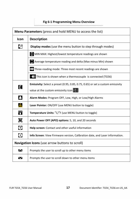
Menu Parameters (press and hold MENU to access the list)
Icon Description
Display modes (use the menu button to step through modes)
MIN MAX: Highest/lowest temperature readings are shown
Average temperature reading and delta (Max minus Min) shown
Three‐reading mode: Three most recent readings are shown
This icon is shown when a thermocouple is connected (TG56)
Emissivity: Select a preset (0.95, 0.85, 0.75, 0.65) or set a custom emissivity
value at the custom emissivity icon
Alarm Modes: Program OFF, Low, High, or Low/High Alarms
Laser Pointer: ON/OFF (use MENU button to toggle)
Temperature Units: oC/oF (use MENU button to toggle)
Auto Power OFF (APO) options: 5, 10, and 20 seconds
Help screen: Contact and other useful information
Info Screen: View Firmware version, Calibration date, and Laser information.
Navigation Icons (use arrow buttons to scroll)
Prompts the user to scroll up to other menu items
Prompts the user to scroll down to other menu items
Fig 6‐1 Programming Menu Overview
FLIR TG54_TG56 User Manual 18 Document Identifier: TG54_TG56‐en‐US_AA
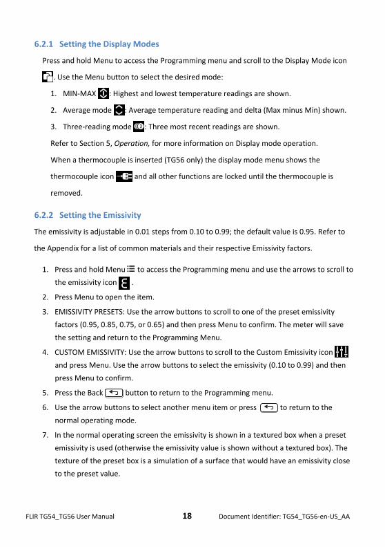
6.2.1 Setting the Display Modes
Press and hold Menu to access the Programming menu and scroll to the Display Mode icon
. Use the Menu button to select the desired mode:
1. MIN‐MAX : Highest and lowest temperature readings are shown.
2. Average mode : Average temperature reading and delta (Max minus Min) shown.
3. Three‐reading mode : Three most recent readings are shown.
Refer to Section 5, Operation, for more information on Display mode operation.
When a thermocouple is inserted (TG56 only) the display mode menu shows the
thermocouple icon and all other functions are locked until the thermocouple is
removed.
6.2.2 Setting the Emissivity
The emissivity is adjustable in 0.01 steps from 0.10 to 0.99; the default value is 0.95. Refer to
the Appendix for a list of common materials and their respective Emissivity factors.
1. Press and hold Menu to access the Programming menu and use the arrows to scroll to
the emissivity icon .
2. Press Menu to open the item.
3. EMISSIVITY PRESETS: Use the arrow buttons to scroll to one of the preset emissivity
factors (0.95, 0.85, 0.75, or 0.65) and then press Menu to confirm. The meter will save
the setting and return to the Programming Menu.
4. CUSTOM EMISSIVITY: Use the arrow buttons to scroll to the Custom Emissivity icon
and press Menu. Use the arrow buttons to select the emissivity (0.10 to 0.99) and then
press Menu to confirm.
5. Press the Back button to return to the Programming menu.
6. Use the arrow buttons to select another menu item or press to return to the
normal operating mode.
7. In the normal operating screen the emissivity is shown in a textured box when a preset
emissivity is used (otherwise the emissivity value is shown without a textured box). The
texture of the preset box is a simulation of a surface that would have an emissivity close
to the preset value.
FLIR TG54_TG56 User Manual 19 Document Identifier: TG54_TG56‐en‐US_AA
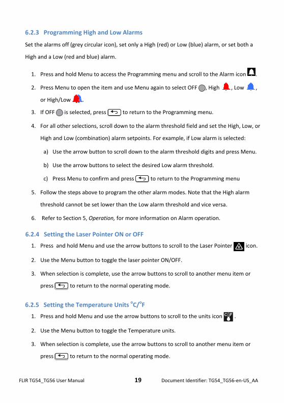
6.2.3 Programming High and Low Alarms
Set the alarms off (grey circular icon), set only a High (red) or Low (blue) alarm, or set both a
High and a Low (red and blue) alarm.
1. Press and hold Menu to access the Programming menu and scroll to the Alarm icon .
2. Press Menu to open the item and use Menu again to select OFF , High , Low ,
or High/Low .
3. If OFF is selected, press to return to the Programming menu.
4. For all other selections, scroll down to the alarm threshold field and set the High, Low, or
High and Low (combination) alarm setpoints. For example, if Low alarm is selected:
a) Use the arrow button to scroll down to the alarm threshold digits and press Menu.
b) Use the arrow buttons to select the desired Low alarm threshold.
c) Press Menu to confirm and press to return to the Programming menu
5. Follow the steps above to program the other alarm modes. Note that the High alarm
threshold cannot be set lower than the Low alarm threshold and vice versa.
6. Refer to Section 5, Operation, for more information on Alarm operation.
6.2.4 Setting the Laser Pointer ON or OFF
1. Press and hold Menu and use the arrow buttons to scroll to the Laser Pointer icon.
2. Use the Menu button to toggle the laser pointer ON/OFF.
3. When selection is complete, use the arrow buttons to scroll to another menu item or
press to return to the normal operating mode.
6.2.5 Setting the Temperature Units oC/oF
1. Press and hold Menu and use the arrow buttons to scroll to the units icon .
2. Use the Menu button to toggle the Temperature units.
3. When selection is complete, use the arrow buttons to scroll to another menu item or
press to return to the normal operating mode.
FLIR TG54_TG56 User Manual 20 Document Identifier: TG54_TG56‐en‐US_AA
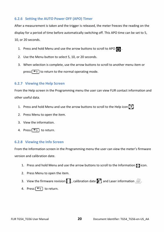
6.2.6 Setting the AUTO Power OFF (APO) Timer
After a measurement is taken and the trigger is released, the meter freezes the reading on the
display for a period of time before automatically switching off. This APO time can be set to 5,
10, or 20 seconds.
1. Press and hold Menu and use the arrow buttons to scroll to APO .
2. Use the Menu button to select 5, 10, or 20 seconds.
3. When selection is complete, use the arrow buttons to scroll to another menu item or
press to return to the normal operating mode.
6.2.7 Viewing the Help Screen
From the Help screen in the Programming menu the user can view FLIR contact information and
other useful data.
1. Press and hold Menu and use the arrow buttons to scroll to the Help icon .
2. Press Menu to open the item.
3. View the information.
4. Press to return.
6.2.8 Viewing the Info Screen
From the Information screen in the Programming menu the user can view the meter’s firmware
version and calibration date.
1. Press and hold Menu and use the arrow buttons to scroll to the Information icon.
2. Press Menu to open the item.
3. View the firmware revision , calibration date , and Laser information .
4. Press to return.
FLIR TG54_TG56 User Manual 21 Document Identifier: TG54_TG56‐en‐US_AA
7 Maintenance
7.1 Battery Replacement
The TG Series is powered by three (3) 1.5V ‘AAA’ batteries.
The batteries are located in a tray housed inside the meter handle. To access the battery
tray, unscrew the cap at the bottom of the meter handle.
Slide the battery tray out of the handle, noting the tray orientation.
Replace the batteries observing correct polarity.
Slide the battery tray back into the handle in the original orientation.
Screw the cap back onto the handle.
7.2 Calibration
The meter is calibrated at the factory prior to shipment. If calibration is required please contact
a local FLIR service center. The TG Series is not user‐serviceable and should only be calibrated
by trained, qualified FLIR personnel.
7.3 Cleaning
Wipe the housing with a dry or damp cloth as needed. Use a high quality lens wipe to remove
dirt or smudges from the meter lenses and display window. Please do not use abrasives or
solvents to clean the meter housing, lenses, or display window.

FLIR TG54_TG56 User Manual 22 Document Identifier: TG54_TG56‐en‐US_AA
8 Specifications
8.1 General Specifications
Display 1.45” Color TFT
Display resolution 128 (W) x 128 (H) pixels
Battery power Three (3) 1.5V ‘AAA’ batteries located in the meter handle
Battery life > 8 hours; typical
Automatic Power OFF User‐adjustable (5, 10, and 20 seconds)
Alarms Color‐coded High, Low, and High/Low combination alarms
Certifications CE/FDA Laser
Warranty 5 years
Accessories Includes Lanyard, Type K thermocouple (TG56), User Guide
Dimensions (H x W x D)/Weight 6.2 x 1.7 x 2.9 in. (158 x 44 x 73mm) / 11 oz. (312g)
8.2 Environmental Specifications
Operating Temperature 14 ~ 113oF (‐10 ~ 45oC)
Storage Temperature ‐22 ~ 131oF (‐30 ~ 55oC)
Relative Humidity 0% ~ 90% [32°F ~ 98.6°F (0°C ~ 37°C)]
0% ~ 65% [98.6°F ~ 113°F (37°C ~ 45°C)]
0% ~ 45% [113°F ~ 131°F (45°C ~ 55°C)]
Non‐condensing (for all ranges above)
FLIR TG54_TG56 User Manual 23 Document Identifier: TG54_TG56‐en‐US_AA
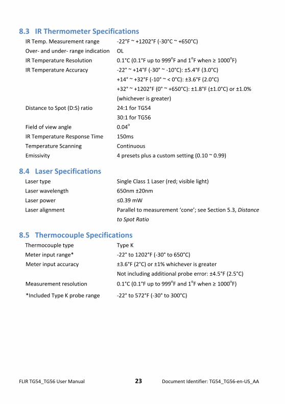
8.3 IR Thermometer Specifications IR Temp. Measurement range ‐22°F ~ +1202°F (‐30°C ~ +650°C)
Over‐ and under‐ range indication OL
IR Temperature Resolution 0.1°C (0.1°F up to 999oF and 1oF when ≥ 1000oF)
IR Temperature Accuracy ‐22° ~ +14°F (‐30° ~ ‐10°C): ±5.4°F (3.0°C)
+14° ~ +32°F (‐10° ~ < 0°C): ±3.6°F (2.0°C)
+32° ~ +1202°F (0° ~ +650°C): ±1.8°F (±1.0°C) or ±1.0%
(whichever is greater)
Distance to Spot (D:S) ratio 24:1 for TG54
30:1 for TG56
Field of view angle 0.04o
IR Temperature Response Time 150ms
Temperature Scanning Continuous
Emissivity 4 presets plus a custom setting (0.10 ~ 0.99)
8.4 Laser Specifications Laser type Single Class 1 Laser (red; visible light)
Laser wavelength 650nm ±20nm
Laser power ≤0.39 mW
Laser alignment Parallel to measurement ‘cone’; see Section 5.3, Distance
to Spot Ratio
8.5 Thermocouple Specifications Thermocouple type Type K
Meter input range* ‐22° to 1202°F (‐30° to 650°C)
Meter input accuracy ±3.6°F (2°C) or ±1% whichever is greater
Not including additional probe error: ±4.5°F (2.5°C)
Measurement resolution 0.1°C (0.1°F up to 999oF and 1oF when ≥ 1000oF)
*Included Type K probe range ‐22° to 572°F (‐30° to 300°C)
FLIR TG54_TG56 User Manual 24 Document Identifier: TG54_TG56‐en‐US_AA
9 Appendices
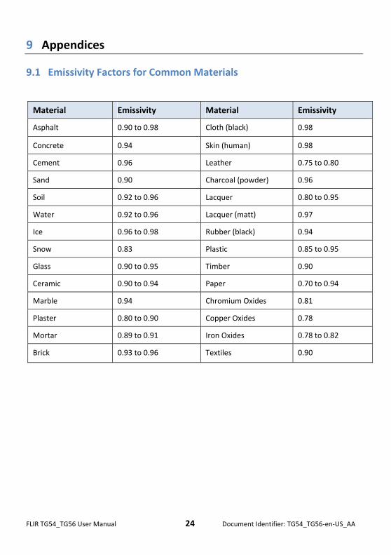
9.1 Emissivity Factors for Common Materials
Material Emissivity Material Emissivity
Asphalt 0.90 to 0.98 Cloth (black) 0.98
Concrete 0.94 Skin (human) 0.98
Cement 0.96 Leather 0.75 to 0.80
Sand 0.90 Charcoal (powder) 0.96
Soil 0.92 to 0.96 Lacquer 0.80 to 0.95
Water 0.92 to 0.96 Lacquer (matt) 0.97
Ice 0.96 to 0.98 Rubber (black) 0.94
Snow 0.83 Plastic 0.85 to 0.95
Glass 0.90 to 0.95 Timber 0.90
Ceramic 0.90 to 0.94 Paper 0.70 to 0.94
Marble 0.94 Chromium Oxides 0.81
Plaster 0.80 to 0.90 Copper Oxides 0.78
Mortar 0.89 to 0.91 Iron Oxides 0.78 to 0.82
Brick 0.93 to 0.96 Textiles 0.90
FLIR TG54_TG56 User Manual 25 Document Identifier: TG54_TG56‐en‐US_AA
9.2 Infrared Energy and IR Thermometer Theory
Infrared energy is part of a complete range of radiation called the electromagnetic spectrum.
The electromagnetic spectrum includes gamma rays, X‐rays, ultraviolet, visible, infrared,
microwaves (RADAR), and radio waves. The only difference is their wavelength or frequency. All
of these forms of radiation travel at the speed of light. Infrared radiation lies between the
visible and RADAR portions of the electromagnetic spectrum.
The primary source of infrared radiation is heat or thermal radiation. Any object which has a
temperature radiates in the infrared portion of the electromagnetic spectrum. Even objects
that are very cold, such as an ice cube, emit infrared. When an object is not quite hot enough to
radiate visible light, it will emit most of its energy in the infrared. For example, hot charcoal
may not give off light, but it does emit infrared radiation, which we feel as heat. The warmer
the object, the more infrared radiation it emits.
IR Thermometers measure an object’s surface temperature. The thermometer’s optics sense an
object’s emitted, reflected, and transmitted energy.
The TG Series translates the sensed information (targeted by the Laser) into a temperature
reading that is displayed in text on the center of the display. If the thermometer measurement
exceeds the published temperature range, the display will indicate OL.
The amount of IR energy emitted by an object is proportional to an object's temperature and its
ability to emit energy. This ability is known as emissivity and is based on the material of the
object and its surface finish. Emissivity values range from 0.1 for a very reflective object to 1.00
for a flat black finish.
The TG Series has both adjustable and preset emissivity settings. There are four (4) presets and
an adjustable emissivity span from 0.10 to 0.99. See the Appendix for a list of common
materials and their respective Emissivity factors. Access the Programming menu (covered in
Section 6) to set the desired emissivity factor.
FLIR TG54_TG56 User Manual 26 Document Identifier: TG54_TG56‐en‐US_AA
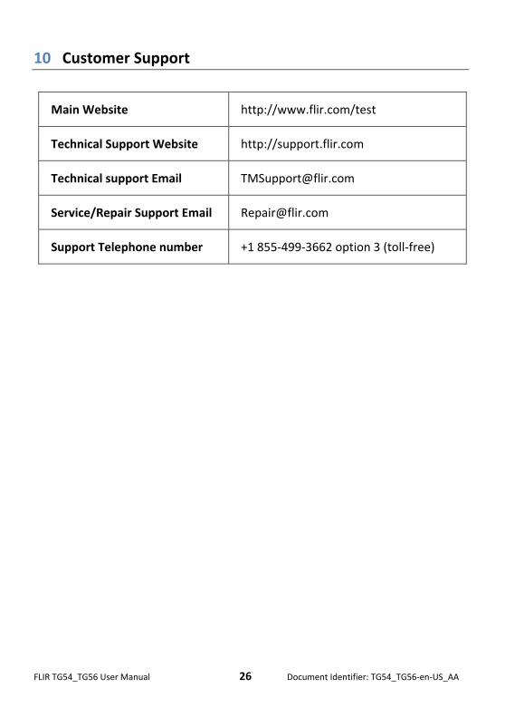
10 Customer Support
Main Website http://www.flir.com/test
Technical Support Website http://support.flir.com
Technical support Email [email protected]
Service/Repair Support Email [email protected]
Support Telephone number +1 855‐499‐3662 option 3 (toll‐free)
FLIR TG54_TG56 User Manual 27 Document Identifier: TG54_TG56‐en‐US_AA
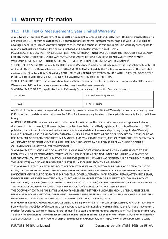
11 Warranty Information
11.1 FLIR Test & Measurement 5 year Limited Warranty A qualifying FLIR Test and Measurement product (the “Product”) purchased either directly from FLIR Commercial Systems Inc.
and affiliates (FLIR) or from an authorized FLIR distributor or reseller that Purchaser registers on‐line with FLIR is eligible for
coverage under FLIR’s Limited Warranty, subject to the terms and conditions in this document. This warranty only applies to
purchases of Qualifying Products (see below) purchased and manufactured after April 1, 2015.
PLEASE READ THIS DOCUMENT CAREFULLY; IT CONTAINS IMPORTANT INFORMATION ABOUT THE PRODUCTS THAT QUALIFY
FOR COVERAGE UNDER THE LIMITED WARRANTY, PURCHASER’S OBLIGATIONS, HOW TO ACTIVATE THE WARRANTY,
WARRANTY COVERAGE, AND OTHER IMPORTANT TERMS, CONDITIONS, EXCLUSIONS AND DISCLAIMERS.
1. PRODUCT REGISTRATION. To qualify for FLIR’s Limited Warranty, Purchaser must fully register the Product directly with FLIR
on‐line at http://www.flir.com/testwarranty within Sixty (60) DAYS of the date the Product was purchased by the first retail
customer (the “Purchase Date”). Qualifying PRODUCTS THAT ARE NOT REGISTERED ON‐LINE WITHIN SIXTY (60) DAYS OF THE
PURCHASE DATE WILL HAVE A LIMITED ONE YEAR WARRANTY FROM DATE OF PURCHASE.
2. QUALIFYING PRODUCTS. Upon registration, Test and Measurement products that qualify for coverage under FLIR’s Limited
Warranty are: TG5x not including accessories which may have their own warranty.
3. WARRANTY PERIODS. The applicable Limited Warranty Period measured from the Purchase data are:
Products Limited Warranty Period
TG5x FIVE (5) Years
Any Product that is repaired or replaced under warranty is covered under this Limited Warranty for one hundred eighty days
(180) days from the date of return shipment by FLIR or for the remaining duration of the applicable Warranty Period, whichever
is longer.
4. LIMITED WARRANTY. In accordance with the terms and conditions of this Limited Warranty, and except as excluded or
disclaimed in this document, FLIR warrants, from the Purchase Date, that all fully registered Products will conform to FLIR’s
published product specifications and be free from defects in materials and workmanship during the applicable Warranty
Period. PURCHASER’S SOLE AND EXCLUSIVE REMEDY UNDER THIS WARRANTY, AT FLIR’S SOLE DISCRETION, IS THE REPAIR OR
REPLACEMENT OF DEFECTIVE PRODUCTS IN A MANNER, AND BY A SERVICE CENTER, AUTHORIZED BY FLIR. IF THIS REMEDY IS
ADJUDICATED TO BE INSUFFICIENT, FLIR SHALL REFUND PURCHASER’S PAID PURCHASE PRICE AND HAVE NO OTHER
OBLIGATION OR LIABILITY TO BUYER WHATSOEVER.
5. WARRANTY EXCLUSIONS AND DISCLAIMERS. FLIR MAKES NO OTHER WARRANTY OF ANY KIND WITH RESPECT TO THE
PRODUCTS. ALL OTHER WARRANTIES, EXPRESS OR IMPLIED, INCLUDING BUT NOT LIMITED TO IMPLIED WARRANTIES OF
MERCHANTABILITY, FITNESS FOR A PARTICULAR PURPOSE (EVEN IF PURCHASER HAS NOTIFIED FLIR OF ITS INTENDED USE FOR
THE PRODUCTS), AND NON‐INFRINGEMENT ARE EXPRESSLY EXCLUDED FROM THIS AGREEMENT.
THIS WARRANTY EXPRESSLY EXCLUDES ROUTINE PRODUCT MAINTENANCE, SOFTWARE UPDATES, AND REPLACEMENT OF
FUSES, OR DISPOSABLE BATTERIES. FLIR FURTHER EXPRESSLY DISCLAIMS ANY WARRANTY COVERAGE WHERE THE ALLEGED
NONCONFORMITY IS DUE TO NORMAL WEAR AND TEAR, OTHER ALTERATION, MODIFICATION, REPAIR, ATTEMPTED REPAIR,
IMPROPER USE, IMPROPER MAINTENANCE, NEGLECT, ABUSE, IMPROPER STORAGE, FAILURE TO FOLLOW ANY PRODUCT
INSTRUCTIONS, DAMAGE (WHETHER CAUSED BY ACCIDENT OR OTHERWISE), OR ANY OTHER IMPROPER CARE OR HANDING OF
THE PRODUCTS CAUSED BY ANYONE OTHER THAN FLIR OR FLIR’S EXPRESSLY AUTHORIZED DESIGNEE.
THIS DOCUMENT CONTAINS THE ENTIRE WARRANTY AGREEMENT BETWEEN PURCHASER AND FLIR AND SUPERSEDES ALL
PRIOR WARRANTY NEGOTIATIONS, AGREEMENTS, PROMISES AND UNDERSTANDINGS BETWEEN PURCHASER AND FLIR. THIS
WARRANTY MAY NOT BE ALTERED WITHOUT THE EXPRESS WRITTEN CONSENT OF FLIR.
6. WARRANTY RETURN, REPAIR AND REPLACEMENT. To be eligible for warranty repair or replacement, Purchaser must notify
FLIR within thirty (30) days of discovering of any apparent defect in materials or workmanship. Before Purchaser may return a
Product for warranty service or repair, Purchaser must first obtain a returned material authorization (RMA) number from FLIR.
To obtain the RMA number Owner must provide an original proof of purchase. For additional information, to notify FLIR of an
apparent defect in materials or workmanship, or to request an RMA number, visit http://www.flir.com. Purchaser is solely
FLIR TG54_TG56 User Manual 28 Document Identifier: TG54_TG56‐en‐US_AA
responsible for complying with all RMA instructions provided by FLIR including but not limited to adequately packaging the
Product for shipment to FLIR and for all packaging and shipping costs. FLIR will pay for returning to Purchaser any Product that
FLIR repairs or replaces under warranty.
FLIR reserves the right to determine, in its sole discretion, whether a returned Product is covered under Warranty. If FLIR
determines that any returned Product is not covered under Warranty or is otherwise excluded from Warranty coverage, FLIR
may charge Purchaser a reasonable handling fee and return the Product to Purchaser, at Purchaser’s expense, or offer
Purchaser the option of handling the Product as a non‐warranty return.
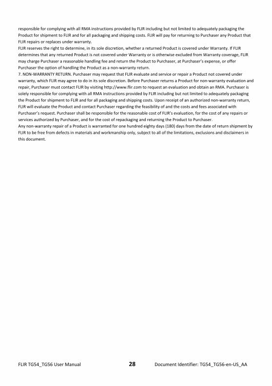
7. NON‐WARRANTY RETURN. Purchaser may request that FLIR evaluate and service or repair a Product not covered under
warranty, which FLIR may agree to do in its sole discretion. Before Purchaser returns a Product for non‐warranty evaluation and
repair, Purchaser must contact FLIR by visiting http://www.flir.com to request an evaluation and obtain an RMA. Purchaser is
solely responsible for complying with all RMA instructions provided by FLIR including but not limited to adequately packaging
the Product for shipment to FLIR and for all packaging and shipping costs. Upon receipt of an authorized non‐warranty return,
FLIR will evaluate the Product and contact Purchaser regarding the feasibility of and the costs and fees associated with
Purchaser’s request. Purchaser shall be responsible for the reasonable cost of FLIR’s evaluation, for the cost of any repairs or
services authorized by Purchaser, and for the cost of repackaging and returning the Product to Purchaser.
Any non‐warranty repair of a Product is warranted for one hundred eighty days (180) days from the date of return shipment by
FLIR to be free from defects in materials and workmanship only, subject to all of the limitations, exclusions and disclaimers in
this document.
FLIR TG54_TG56 User Manual 29 Document Identifier: TG54_TG56‐en‐US_AA
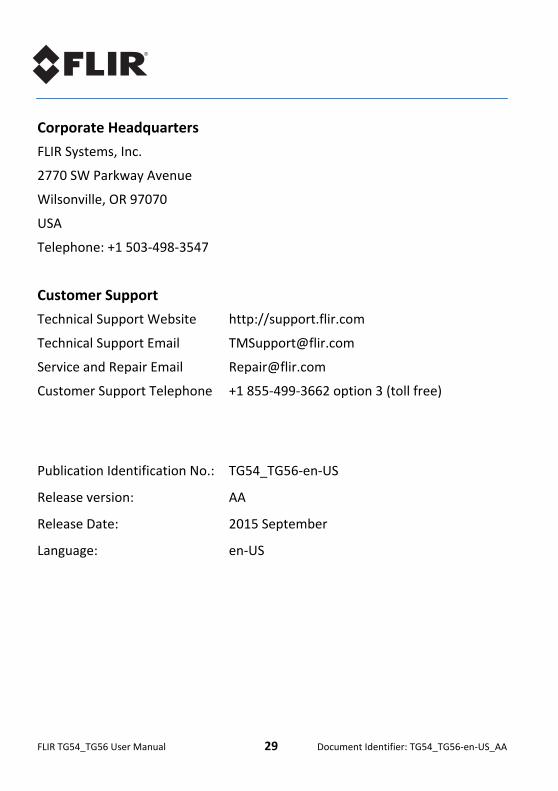
Corporate Headquarters
FLIR Systems, Inc.
2770 SW Parkway Avenue
Wilsonville, OR 97070
USA
Telephone: +1 503‐498‐3547
Customer Support
Technical Support Website http://support.flir.com
Technical Support Email [email protected]
Service and Repair Email [email protected]
Customer Support Telephone +1 855‐499‐3662 option 3 (toll free)
Publication Identification No.: TG54_TG56‐en‐US
Release version: AA
Release Date: 2015 September
Language: en‐US