user manual - elma.dk tel. +1 860-399-4222 fax. +1 860-399-3180 email [email protected] web ...
TRANSCRIPT

User Manual
©2011-2015 ALL-TEST Pro, LLC All Rights Reserved Rev 2015 – 01L
ALL-TEST PRO® 33 INDUSTRIAL For Firmware IND130516A4 & IND130516B4 or higher

ALL-TEST PRO® 33 IND User Manual Rev 2015 – 01L
- 1 -
SAFETY WARNINGS The Device Under Test (DUT) must be fully de-energized before AT33
instrument can be connected for any test
Please do not touch any test leads during any on-going tests For more details, please refer to “SAFETY WARNINGS AND PRECAUTIONS” section on Page 4.
CONTACT INFORMATION ALL-TEST Pro, LLC P.O. Box 1139 Old Saybrook, CT 06475 USA
Tel. +1 860-399-4222
Fax. +1 860-399-3180
Email [email protected]
Web www.alltestpro.com
NOTE: Color illustrations and images are used in this manual and we recommend
printing it using a color printer, if a hardcopy is desired.

ALL-TEST PRO® 33 IND User Manual Rev 2015 – 01L
- 2 -
CONTENTS
SAFETY WARNINGS …………………………………….………………………………………………….. 1
CONTACT INFORMATION …………………………….………………………………………………….. 1
INTRODUCTION …….…………………………………….………………………………………………….. 3
SAFETY WARNINGS AND PRECAUTIONS………………………………………………………….. 4
INSTRUMENT WARNINGS …….……………………………………………………………………….. 4
ALL-TEST PRO 33 KIT ………………………………………………………………………………………. 5
INSTRUMENT CONNECTIONS LAYOUT ……………………………………………………………. 6
FRONT PANEL LAYOUT …….………………………………………………………………………………. 7
BATTERIES AND CHARGING …..…………………………………………………………………………. 8
BASIC INSTRUMENT OPERATION ....…………………………………………………………………. 8
MAIN MENU ……………………………………………………………………………………………………. 9
AC MOTOR TESTING …..……………………………………………………………………………………. 9
STATIC TESTS …………………………………………………………………………………………………… 11
1. CONTAMINATION TEST (DF and CAPACITANCE) …………………………………………. 11
2. INSULATION RESISTANCE TEST (MΩ) ………………………………………………………….. 13
3. RESISTANCE AND TEST VALUE STATIC TEST (R, TVS) ……..……………………………. 14
DYNAMIC TEST ………………………………………………………………………………………………… 15
VIEWING THE TEST RESULTS …………….……………………..……………………………………… 16
SAVING TO MEMORY ……………………………………………………………………………………... 19
COMPARE TO REF ………………………….……………………………………………………………….. 22
VIEWING / DELETING SAVED TESTS ………………………………………………………………… 23
SET DATE / TIME …………………………………………………………………………………………….. 25
PC COMMUNICATION …..………………………………………………………………………………… 25
INSTRUMENT FIRMWARE VERSION ……………………………………………………………….. 27
SPECIFICATIONS ……………………………………………………………………………………………… 28
ADDENDUM A- AT33 TESTING GUIDE ………………………………………………………………. 31
DISCLAIMER, COPYRIGHT, & TRADE MARKS …………………………………………………….. 40

ALL-TEST PRO® 33 IND User Manual Rev 2015 – 01L
- 3 -
INTRODUCTION to the ALL-TEST PRO® 33
Test Instrument / Analyzer / Data Collector for Electrical Motors
Congratulations on your purchase of the new patented ALL-TEST PRO® 33 Motor Circuit
Analyzer (AT33) from ALL-TEST Pro, LLC (ATP). The ATP AT33 is the first in a new series of hand-
held Motor Test Instruments and is available in the Industrial (IND) or in the Electric Vehicle (EV)
version. The IND version is optimized to test AC induction motors with squirrel-cage rotors that
operate up to 1000VAC (if your testing application includes motor operating voltages that
exceed 1000V contact us at [email protected] for testing options). The EV version is for
testing Permanent Magnet (PM) type motors and motor/generators used in hybrid and electric
vehicles. Additionally, the EV version has application with testing other types of PM motors.
Contact [email protected] for further information.
The 33 series forms the base in a complete system solution for stand-alone trouble shooting/
fault localization; quality control of stored or incoming new/repaired motors; as well as data
collection and trending for early fault detection when combined with the optional PC software.
The ALL-TEST PRO 33 performs Motor Circuit Analysis (MCA) as a series of low voltage tests to
identify faults inside an electric motor. The AT33 detects winding contamination, stator faults
such as turn-to-turn and coil-to-coil, open connections, ground faults, and broken/fractured
rotor bars. Experience has proven that the ALL-TEST PRO series of Motor Test Instruments are
the most powerful and easiest to use diagnostic tools available for de-energized testing of
motors in today’s industry.
The AT33 is designed to be used as a stand-alone unit in the field or workshop, or with optional
Windows based software for further analysis, reporting, trending and database. Has a built-in
real time clock and large memory for storage of test and reference data. The instruments are
built to exacting standards and rugged to handle the daily use in tough industrial environments.
The rechargeable Lithium batteries support eight hours or more of testing and data collection*.
* Assumes most testing is phase to phase. Performing insulation to ground testing in applications where
there are long cable runs will increase the drain on the battery. Therefore, user may not get 8 hours of
use between battery charges.

ALL-TEST PRO® 33 IND User Manual Rev 2015 – 01L
- 4 -
SAFETY WARNINGS AND PRECAUTIONS
Safety Warnings and Precautions must be read and understood before the instrument is used.
They must be observed during use.
Follow all safety rules of your company and OSHA (or country equivalent) for off-line
testing methods, including the wearing of appropriate Personal Protective Equipment (PPE).
Improper or unsafe operation of the ALL-TEST PRO® 33 is the sole responsibility of the user.
The ALL-TEST PRO® 33 is only to be used on de-energized motors. Connecting the instrument
to live voltage will destroy the unit and void the warranty. Always verify the motor circuit is
de-energized before connecting the AT33.
Ensure that all power has been removed from the circuit being tested, including static
power stored in capacitors. Discharge all capacitors being tested. During testing, ensure that
one leg of any power factor correction capacitor or lightning arrestor that is in the test circuit
are disconnected to avoid erroneous test results.
For MCA testing, the ALL-TEST PRO® 33 sends out a low voltage, high frequency test signal not
harmful to the technician or most electronic equipment (variable frequency drives and soft
starters). However, electronic equipment and personnel must observe appropriate safety
considerations (disconnect electronic equipment) when performing the insulation to Ground
Resistance Test (Meg-Ohm test).
Test leads, including crocodile clips, must be in good order, clean and have no broken or
cracked insulation. During test, do not touch any test leads since it potentially exposes the
user(s) to high voltage and causes errors in the final test results.
INSTRUMENT WARNINGS
Do not open the main body of the instrument. Electrostatic charges may damage surface
mount electronics. Additional battery packs can be purchased from ALL-TEST Pro, but care
must be exercised during battery installation, as electrostatic charges may damage surface
mount electronics. Contact your distributor of the AT33 or ALL-TEST Pro (+1 860.399.4222 or
email [email protected]) to purchase a battery pack and for battery installation
instructions. NOTE: Only approved original equipment (OEM) battery pack should used and
use of non-OEM types will void your warranty!

ALL-TEST PRO® 33 IND User Manual Rev 2015 – 01L
- 5 -
Use only the supplied charger for charging the instrument. It is an integral part of the
charging circuit. Using the wrong charger could damage your instrument and void the
warranty.
ALL-TEST PRO 33 KIT
STANDARD EQUIPMENT
ALL-TEST PRO 33 with back-lit graphic LCD screen (128x64 pixel)
3x Test leads with Kelvin Clips
1x Test lead with 4mm safety plug and “Dolphin” clip
Battery charging adapter
Attaché type hard case with pre-cut foam liner
User Manual on CD
AVAILABLE ACCESSORIES
Windows (XP/7) based software for database storage, further analysis, reporting
and trending
USB cable 1m (for PC communication)
Soft carrying pouch for instrument and test leads
Battery pack and DC charger
TRAINING
Continuing Education Accredited Training Courses are held at various locations throughout the
world. In addition, all of the ALL-TEST Pro training courses can be customized and brought to
your plant site. Contact ALL-TEST Pro training department at www.alltestpro.com for further
information.
WARRANTY
One year limited warranty. See ALL-TEST Pro Terms and Conditions for details.

ALL-TEST PRO® 33 IND User Manual Rev 2015 – 01L
- 6 -
INSTRUMENT CONNECTIONS LAYOUT
1. Phase 1 Test Lead input/output port BLACK
2. Phase 2 Test Lead input/output port BLUE
3. Phase 3 Test Lead input/output port RED
4. 500V & 1000V / Dissipation Factor / Capacitance output test port YYYeeellllllooowww
WARNING: Risk of electric shock!
5. USB port (type B) for PC communication
6. Charger input DC 9V, 1.7A (center pin + polarity) CAUTION: Only use the supplied
charger for charging. Using the wrong charger could damage your instrument and void the
warranty. Keep instrument plugged into charger when not in use.
ALL-TEST PRO® 33 IND User Manual Rev 2015 – 01L
- 7 -
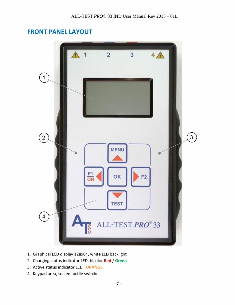
FRONT PANEL LAYOUT
1. Graphical LCD display 128x64, white LED backlight
2. Charging status indicator LED, bicolor Red / Green
3. Active status indicator LED ORANGE
4. Keypad area, sealed tactile switches

ALL-TEST PRO® 33 IND User Manual Rev 2015 – 01L
- 8 -
BATTERIES AND CHARGING The built-in rechargeable Lithium (Li-ION) batteries support eight hours or more of normal
testing.
2.5 hours is typically necessary to fully charge the battery. Do not charge when ambient
temperature is below or above range as listed in the specification document. Charge the battery
if the Tester is not used for extended periods.
CAUTION: Only use the supplied charger for charging. Using the wrong charger can damage your instrument.
Charging status is indicated by bicolor LED to the left of keyboard:
Red = Battery conditioning and charging, Green = Charge complete (Done)
Red + Green = Sleep mode or temperature fault, OFF = Charger not connected
Battery voltage is independently monitored and indicated in the main menu, as one of four
possible levels or will show the word “LOW”.
When the charger is plugged into line power the charging circuit automatically resumes
charging when the battery voltage falls below the preset threshold.
Note: The Li-ION batteries have built in over-discharge protection circuits, activated if the
battery pack voltage falls below a threshold that will disconnect the battery pack resulting in no
power! The solution is to recharge the batteries.
BASIC INSTRUMENT OPERATION Turning the instrument ON:
Press the "ON" key for a few seconds until the display lights up and shows the main menu. Instrument will power off after approximately five minutes of inactivity.
Note: If the instrument does not turn on, the most likely cause would be that the Li-ION
batteries built-in over discharge protection circuits have switched off, resulting in no power.
The solution is to connect the charger to the instrument in order to recharge the batteries.
Turning the instrument OFF:
Select the "PWR OFF" icon in the main menu with the arrow keys and then press "OK" key.
How to RESET the instrument:
Simultaneously press the left and right arrow keys for a few seconds and then release.
This will perform a forced hardware & firmware reset and will return the display back to the
main menu.

ALL-TEST PRO® 33 IND User Manual Rev 2015 – 01L
- 9 -
MAIN MENU
The MAIN MENU presents the user with the following main selection icons and information:
“IND” icon selects Testing Industrial AC Motors using all available instrument features.
“DYN” icon selects “Dynamic only” motor testing.
“INS” icon selects “Insulation Resistance only” testing.
“SET” icon selects various set and support functions.
“PWR OFF” icon selects power off.
Battery voltage status indicator shows one of four levels or “LOW”.
Real Time Clock Date and Time information.
AC MOTOR TESTING - STATIC & DYNAMIC The new Patented & Patent Pending analysis methods and measuring technologies are divided
into two main testing types: “STATIC” and “DYNAMIC”.
The term “STATIC” refers to the testing methods possible when the rotor shaft is not accessible
for rotation. I.e. rotor shaft position is fixed.
The term “DYNAMIC” refers to all testing methods possible when the rotor shaft is accessible
for manual rotation, whether by hand or other aid, during testing.
After completing a test “path” the AT33 will automatically “ANALYZE” the test result of each
parameter and presents the result in a user-friendly format. Analysis results include one of
three possible levels: “OK”, “WARN” or “BAD” based on the preset rules. In case only “STATIC”
testing was possible the user has the option to compare the new results with already preloaded
or saved record in the memory, or to save the current test as a baseline reference test.
Saved test records can be uploaded to the optional PC software for further analysis, trending,
data base management and report generation.

ALL-TEST PRO® 33 IND User Manual Rev 2015 – 01L
- 10 -
“STATIC” – tests and measuring functions “Test Value Static / Reference Value Static” (patented): Makes measurements on all three
phases and calculates a “Test Value Static”, which when compared to a baseline “Reference
Value Static”, becomes a powerful combined fault indicator for Rotor and Stator faults. The
“Reference Value Static” is normally saved from the first time the motor is tested (a baseline
test) or can be saved from a known good motor when you have many of the exact same motor
type.
Contamination: Measures the Dissipation Factor (DF) and the capacitance between motor
frame – stator windings.
Resistance: 0-999Ω, resolution 0.01mΩ. True 4-wire Kelvin measurement for accurate low
resistance results (includes automatic compensation for thermoelectric offset voltages).
Insulation Resistance: 0 – 999MΩ @1000V, 0 – 500MΩ @500V
Static tests (except for DF and Capacitance) can be performed directly at the motor or from
the starter or motor drive. However, testing from the starter or motor drive can introduce
external sources of interference that can influence the test results. User should repeat any
test from the starter/drive to verify measurements are repeatable.
“DYNAMIC” – tests and measuring functions “Test Signature” (patented): Measures, in real time during manual rotation, a number of
parameters in all three phases which together forms the “Test Signature” for the rotor and
stator. The "Test Signature” is then automatically analyzed in the AT33 and gives the user
immediate results for Stator and Rotor status. The “Test Signature” can also be uploaded to the
optional PC software and evaluated further by a trained technician.
Dynamic tests are best performed directly at the motor. Testing from the starter or motor
drive can introduce external sources of interference that can adversely influence the test
results.

ALL-TEST PRO® 33 IND User Manual Rev 2015 – 01L
- 11 -
RECOMMENDED TESTING PROCEDURES 1) Prior to installing the motor a DF/C + Insulation + Static + Dynamic test should be
performed directly at the motor leads and then saved as a reference test.
2) After the motor is installed then an Insulation + Static test should be performed from the
starter/drive and then saved as another reference test. This test should be repeated to
verify stable results are achieved. If erratic results are seen then consult Addendum A for
guidelines.
3) Subsequent Insulation + Static testing can be done whether for trouble-shooting or other
purposes. If a change in either the Insulation or Static test is observed then both tests
should be performed at the motor with incoming leads removed from the motor.
4) This new Insulation + Static test at the motor terminals should now be compared to the
initial reference static test that is mentioned in item 1.
a. If the values have not changed from the initial static test then likely the problem
is related to cables/connections between starter/drive and motor.
b. If values have changed from initial static test then the user will need to perform a
complete DF/C + Insulation + Static + Dynamic to determine the root cause for
this change.
STATIC TESTS
1. CONTAMINATION TEST (DF and CAPACITANCE)
The Dissipation Factor test (DF) & Capacitance test (C) of the AT33 is a low voltage
method to measure the Dissipation Factor [also known as tan delta (loss angle)] and the
Capacitive system inside the motor formed by the motor frame and the stator windings. Due to
the inherently high impedance nature of the DF & C test the AT33 connection is designed to
form a shielded test setup together with the motor object under test.
All DF & Capacitance testing should be performed directly on the motor terminals as instructed
and pictured in this Manual.
Only the supplied (shielded) test leads and clips should be used. The use of any additional
cable(s) between the test clips and motor terminals can introduce hum and/or other
interference that can result in erratic readings for DF and C. In addition, longer cable lengths
can also add the influence of the cable itself.
In order to get the highest possible accuracy for the DF test, the instrument should be allowed
to have a warm up time of approximately 10 seconds after powering “ON” (this allows time for
the DC and offset levels to stabilize). Note that the specification for DF and Capacitance is based
ALL-TEST PRO® 33 IND User Manual Rev 2015 – 01L
- 12 -
on battery-powered operation. The USB communication cable cannot be connected to a
computer during the Contamination test described below.
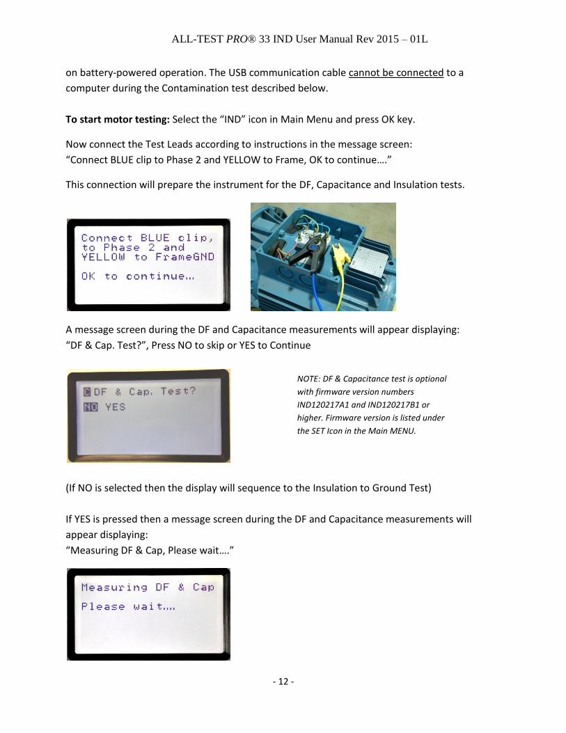
To start motor testing: Select the “IND” icon in Main Menu and press OK key.
Now connect the Test Leads according to instructions in the message screen:
“Connect BLUE clip to Phase 2 and YELLOW to Frame, OK to continue….”
This connection will prepare the instrument for the DF, Capacitance and Insulation tests.
A message screen during the DF and Capacitance measurements will appear displaying:
“DF & Cap. Test?”, Press NO to skip or YES to Continue
(If NO is selected then the display will sequence to the Insulation to Ground Test)
If YES is pressed then a message screen during the DF and Capacitance measurements will
appear displaying:
“Measuring DF & Cap, Please wait….”
NOTE: DF & Capacitance test is optional
with firmware version numbers
IND120217A1 and IND120217B1 or
higher. Firmware version is listed under
the SET Icon in the Main MENU.

ALL-TEST PRO® 33 IND User Manual Rev 2015 – 01L
- 13 -
After the DF and Capacitance test is complete then the display will show the measured values.
Press “OK to continue… or MENU to remeasure…”
2. INSULATION RESISTANCE TEST (MΩ) Next step is the selection of “Insulation Test?” Select “NO” or “YES” and press OK.
If “YES” is selected “---” will be displayed indicating an empty start value for MΩ.
Select the desired test voltage by pressing the F2 key, which will toggle between the two
available selections: 500V or 1000V. NOTE: See Item 8, page 39 for guidelines to proper test
voltage.
To perform an Insulation resistance test:
Press “TEST” key until the MΩ value becomes stable or >500MΩ is displayed, and then OK to
continue.
WARNING: Risk of electric shock! Pressing the TEST key will output the selected
test voltage of 500V or 1000V on the yellow output port and illuminate orange status LED.
ALL-TEST PRO® 33 IND User Manual Rev 2015 – 01L
- 14 -
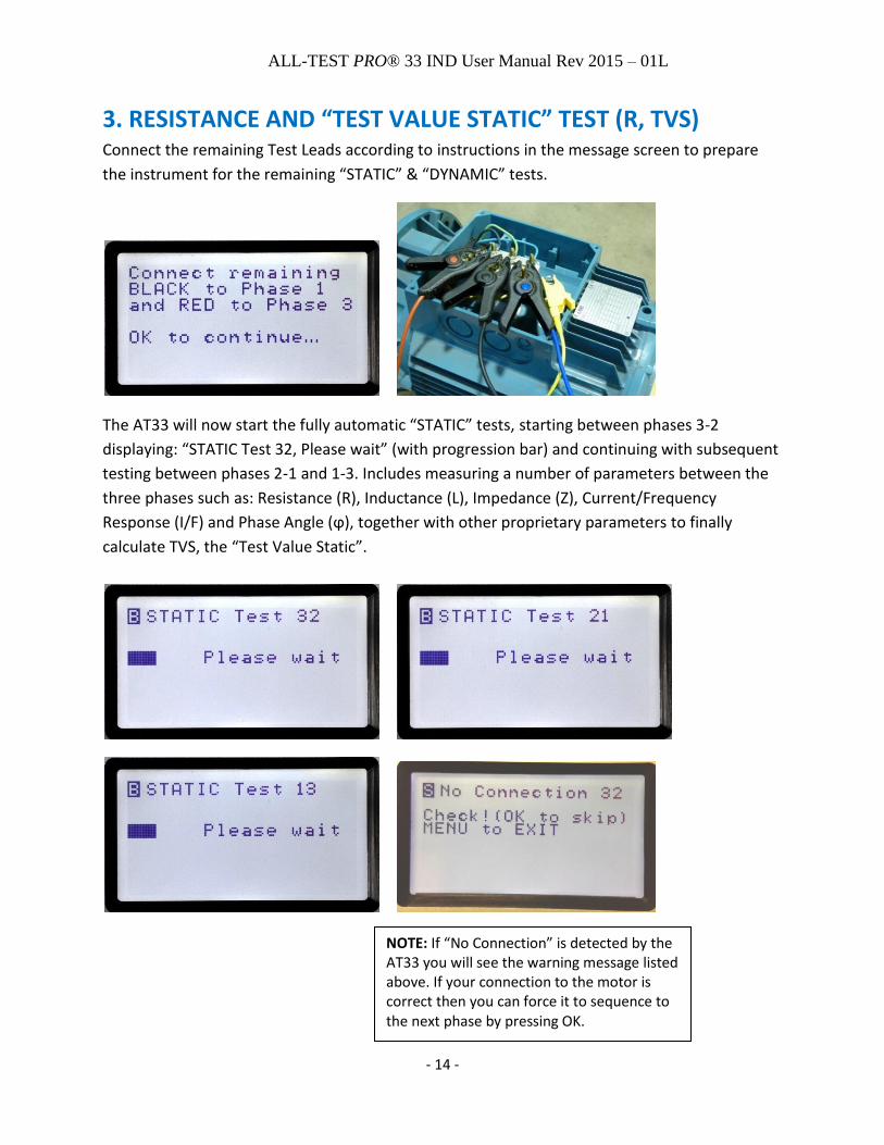
3. RESISTANCE AND “TEST VALUE STATIC” TEST (R, TVS) Connect the remaining Test Leads according to instructions in the message screen to prepare
the instrument for the remaining “STATIC” & “DYNAMIC” tests.
The AT33 will now start the fully automatic “STATIC” tests, starting between phases 3-2
displaying: “STATIC Test 32, Please wait” (with progression bar) and continuing with subsequent
testing between phases 2-1 and 1-3. Includes measuring a number of parameters between the
three phases such as: Resistance (R), Inductance (L), Impedance (Z), Current/Frequency
Response (I/F) and Phase Angle (ϕ), together with other proprietary parameters to finally
calculate TVS, the “Test Value Static”.
NOTE: If “No Connection” is detected by the AT33 you will see the warning message listed above. If your connection to the motor is correct then you can force it to sequence to the next phase by pressing OK.

ALL-TEST PRO® 33 IND User Manual Rev 2015 – 01L
- 15 -
DYNAMIC TEST The next step provides the option to select a “Dynamic Test?”. Select “NO” or “YES” and press
OK. If “NO” is selected then the instrument will skip the Dynamic Test and go directly to the
“Result Menu Screen”. Selecting “YES” will start the Dynamic test.
Start by turning the Rotor as slowly and smoothly as possible by using the bar graph as a visual
feedback aid. Continue turning/rotating the rotor while the AT33 automatically switches to the
next “phase to phase” connection displayed in the following order:
NOTE: If “No Connection” is detected by the instrument you
will see the warning message listed above. If your connection
to the motor is correct then you can force it to sequence to
the next phase by pressing OK.
NOTE: When performing a Dynamic test it is important to
watch the AT33 display screen while turning the motor shaft.
The bar will move horizontally across the screen while you are
rotating the motor shaft. If little (or no) movement occurs
then it is possible it will not sequence to the next phase during
the dynamic test. You can force the 33 to sequence to the next
phase by pressing OK. This does not mean that the motor is
necessarily bad, but instead may relate to the
design/construction of the motor. See MISC, item 3, page 36
for more information.

ALL-TEST PRO® 33 IND User Manual Rev 2015 – 01L
- 16 -
Rotation Speed Guidelines
Start by turning the Rotor slowly and as smoothly as possible by using the bar graph as a visual
feedback aid.
Maximum recommended rotor shaft rotational speed for 2-pole motor = 100 RPM
Maximum recommended rotor shaft rotational speed for 4-pole motor = 50 RPM
Maximum recommended rotor shaft rotational speed for 6-pole motor = 33 RPM
Maximum recommended rotor shaft rotational speed for 8-pole motor = 25 RPM
Maximum recommended rotor shaft rotational speed for 10-pole motor = 20 RPM
Maximum recommended rotor shaft rotational speed for 12-pole motor = 17 RPM
VIEWING THE TEST RESULTS After the STATIC and DYNAMIC tests are done, the instrument will automatically analyze,
calculate and display the Result Menu screen, reporting OK, WARN, BAD or NoR = No Reading.
NOTE: Additional information regarding analysis of the results is located in the Addendum.
RESISTANCE deviation Displayed Result
< 3 % OK
≥ 3% < 5 % WARN
≥ 5 % BAD
No Reading NoR
STATOR signature dev Displayed Result
< 1.1 % OK
≥ 1.1% < 3 % WARN
≥ 3 % BAD
Only STATIC test done use REF (TVS)
Concentric Windings CC* See Addendum
ROTOR signature dev. Displayed Result
< 10 % OK
≥ 10 % < 15 % WARN
≥ 15 % BAD
Only STATIC test done use REF (TVS)
Small Signature Variation With < 2 % variation
< 2
Note: Rotor analyze is proprietary patented method

ALL-TEST PRO® 33 IND User Manual Rev 2015 – 01L
- 17 -
CONTAMINATION DF% Displayed Result
≤ 6 % OK
> 6 % ≤ 10 % WARN
> 10 % BAD
No Reading NoR
The Result Menu screen has selectable submenus to display test result details, including Rotor
and Stator graphical “Test Signature Pattern”, if Dynamic test was done. If only STATIC test was
done the Rotor and Stator fields will display “use REF” and subsequent sub menu will show the
TVS =“Test Value Static” number.
Use arrow UP & DOWN keys to select item then press OK to enter sub menu and view details.
Press OK or MENU to return when done.
The Resistance Submenu will display actual R-values and % deviation. % deviation is calculated
by comparing each phase to the average of the three-phases.
The Stator Submenu will display the “Test Signature Pattern” if DYNAMIC test was done. If only
STATIC tests were done then the TVS=“Test Value Static” (dimensionless) will be displayed.
Rotor has identical submenus as for Stator above!
The center solid line is the Stator signature and represents the deviation of the mean values
during rotation for each phase. The two black doted lines represent the Rotor Signature and
include an upper and lower signature.
INSULATION MΩ Displayed Result
≥ 20 MΩ OK
≥ 1.5 MΩ < 20 MΩ WARN
< 1.5 MΩ BAD
No Reading NoR

ALL-TEST PRO® 33 IND User Manual Rev 2015 – 01L
- 18 -
The image below is generated using the optional computer software (not the same motor as above)
Dynamic Signature Analysis The Green line is the Stator signature and represents the deviation of the mean values during rotation for each phase. Note that for Phase 1-3, the Stator signature is slightly elevated above the other two phases. This indicates the mean values for Phase 1-3 are slightly higher than the other two phases, but are within acceptable limits and this stator is in good condition. The two black doted lines represent the Rotor Signature and include an upper and lower signature. This represents the deviation of the peak values during rotation. As the output of the instrument is sinusoidal and the response of the motor will be sinusoidal, there will be peak values both positive and negative. There are 8 dots for each phase and if this were an 8-pole motor then this represents 1 full revolution of the motor shaft. If this were a 2-pole motor then it represents 4 revolutions of the motor shaft. If this were a 12-pole motor then it represents ¾ of a revolution of the motor shaft. With this Rotor signature there is a slight variation in the distribution of the peak values, but as they are within our limit, this rotor is in good condition. The % change in impedance represents the change in impedance during rotation of the shaft. Contamination Submenu will display DF in % and Capacitance in nF. If C is less than 1% it will
display <1.
Each Phase
Rotor Signature Upper
Rotor Signature Lower
% Change in Impedance
during rotation
Stator Signature (3 phases)

ALL-TEST PRO® 33 IND User Manual Rev 2015 – 01L
- 19 -
Insulation Submenu will display Insulation resistance in MΩ or >500MΩ or --- MΩ (if NoR)
SAVING to MEMORY The instrument can store a maximum total of 819 records in the internal memory as “TEST” or
“REF” record or any mix of the two. The only difference between the two record types is how
they have been tagged by the user prior to saving: “SAVE” (as a TEST record) or “SAVE AS REF”
(as a Reference record).
SAVE/REF selection will display Submenu for saving and comparing to REF functions:
Selecting QUICK SAVE allows the user to SAVE a test by just entering alphanumeric characters
into the Motor ID/Ser# field.
Use arrow keys and OK key to select and enter the alphanumeric characters available on rows 1,
2 and 3.
Cancel will take you back to the Results screen. PREV is not functional in this particular mode.

ALL-TEST PRO® 33 IND User Manual Rev 2015 – 01L
- 20 -
SAVE and SAVE as REF allows the user to SAVE a test (or SAVE as REF) that includes additional
data such as Company, Motor Type, HP, etc.
Selecting either will display the “Input Motor Data” parameters screen starting with “Company”.
Use arrow keys and OK key to select and enter the alphanumeric characters available on rows 1,
2 and 3.
Important Note: All Motor Data information is optional input, but we strongly
recommend to fill in at least one of the following three key motor data:
“Location”, “Motor ID/Ser. #” and “Motor Type”
NOTE: Date & Time of test is included with the test data (from instruments’ internal clock).
Move cursor with arrow keys to highlight the “NEXT” Motor Data command when done with
“Company” and press OK for the next Motor Data “Location”.
Enter Motor “Location” as desired.
ALL-TEST PRO® 33 IND User Manual Rev 2015 – 01L
- 21 -
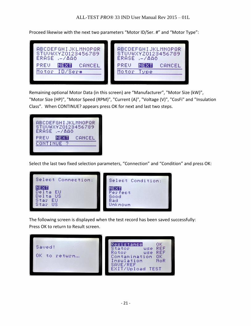
Proceed likewise with the next two parameters “Motor ID/Ser. #” and “Motor Type”:
Remaining optional Motor Data (in this screen) are “Manufacturer", "Motor Size (kW)",
"Motor Size (HP)", "Motor Speed (RPM)", "Current (A)", "Voltage (V)", "CosFi" and "Insulation
Class”. When CONTINUE? appears press OK for next and last two steps.
Select the last two fixed selection parameters, “Connection” and “Condition” and press OK:
The following screen is displayed when the test record has been saved successfully:
Press OK to return to Result screen.
ALL-TEST PRO® 33 IND User Manual Rev 2015 – 01L
- 22 -
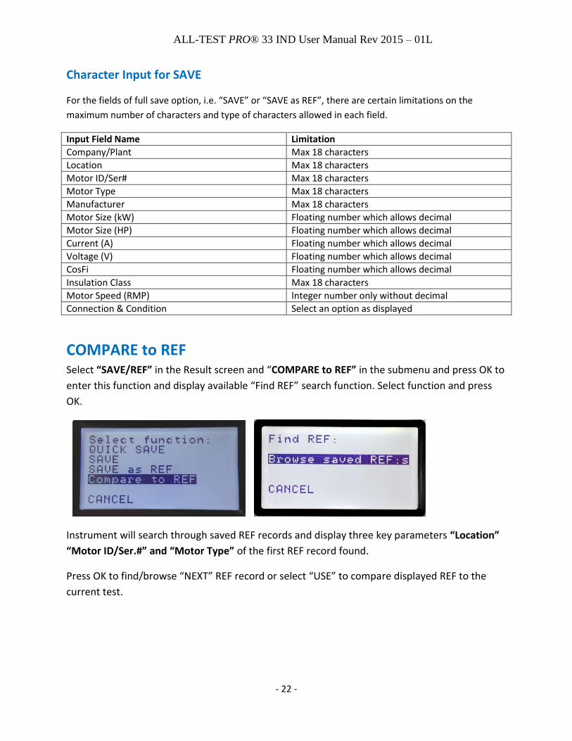
Character Input for SAVE
For the fields of full save option, i.e. “SAVE” or “SAVE as REF”, there are certain limitations on the
maximum number of characters and type of characters allowed in each field.
Input Field Name Limitation
Company/Plant Max 18 characters
Location Max 18 characters
Motor ID/Ser# Max 18 characters
Motor Type Max 18 characters
Manufacturer Max 18 characters
Motor Size (kW) Floating number which allows decimal
Motor Size (HP) Floating number which allows decimal
Current (A) Floating number which allows decimal
Voltage (V) Floating number which allows decimal
CosFi Floating number which allows decimal
Insulation Class Max 18 characters
Motor Speed (RMP) Integer number only without decimal
Connection & Condition Select an option as displayed
COMPARE to REF Select “SAVE/REF” in the Result screen and “COMPARE to REF” in the submenu and press OK to
enter this function and display available “Find REF” search function. Select function and press
OK.
Instrument will search through saved REF records and display three key parameters “Location”
“Motor ID/Ser.#” and “Motor Type” of the first REF record found.
Press OK to find/browse “NEXT” REF record or select “USE” to compare displayed REF to the
current test.

ALL-TEST PRO® 33 IND User Manual Rev 2015 – 01L
- 23 -
The AT33 will display the result of the comparison as a ±% deviation of the current “Test Value
Static” to the saved REF “Test Value Static” (TVS). In addition it will also display one of these
findings: OK, WARN, or BAD according to preset limits:
TVS deviation Displayed Result
< 3 % OK
≥ 3% < 5 % WARN
≥ 5 % BAD
EXIT/Upload TEST Submenu to select EXIT or Upload current TEST without saving.
To send a single test record to PC software via the USB connection select “Upload TEST” and
press OK. The right hand orange Status LED will be “ON” during the short data transmission
time.
VIEWING / DELETING SAVED TESTS Functions are available by selecting the “SET” icon in the main menu.

ALL-TEST PRO® 33 IND User Manual Rev 2015 – 01L
- 24 -
And then select “VIEW/DELETE Record”
Menu choices include: “VIEW Test Records”, “DELETE last Record”, and “CANCEL”
VIEW Test Records allows you to view any record in memory
DELETE Last Record is the only delete function the instrument offers.
ALL-TEST PRO® 33 IND User Manual Rev 2015 – 01L
- 25 -
NOTE: The computer software will allow you to download all test results from instrument memory, View
them, Save them, and upload back into the instrument. See the software manual for details.
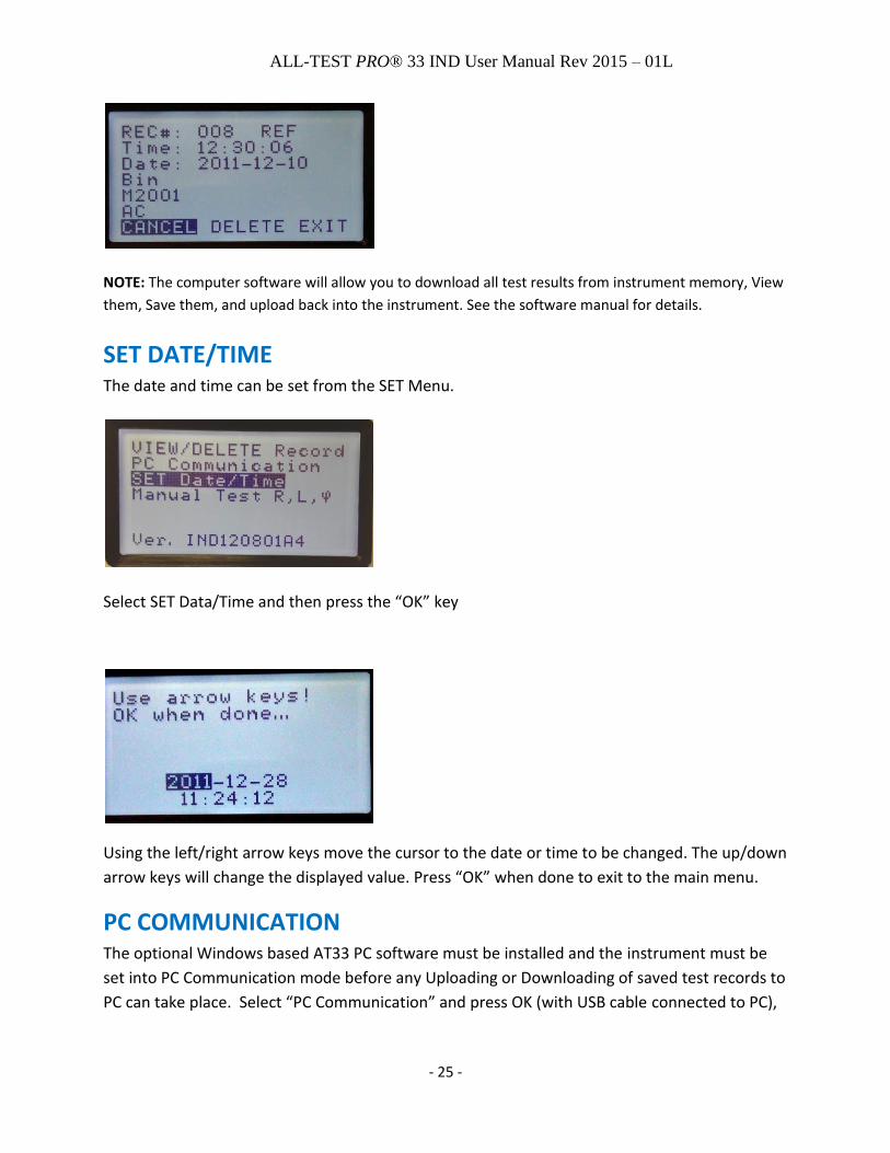
SET DATE/TIME The date and time can be set from the SET Menu.
Select SET Data/Time and then press the “OK” key
Using the left/right arrow keys move the cursor to the date or time to be changed. The up/down
arrow keys will change the displayed value. Press “OK” when done to exit to the main menu.
PC COMMUNICATION The optional Windows based AT33 PC software must be installed and the instrument must be
set into PC Communication mode before any Uploading or Downloading of saved test records to
PC can take place. Select “PC Communication” and press OK (with USB cable connected to PC),
ALL-TEST PRO® 33 IND User Manual Rev 2015 – 01L
- 26 -
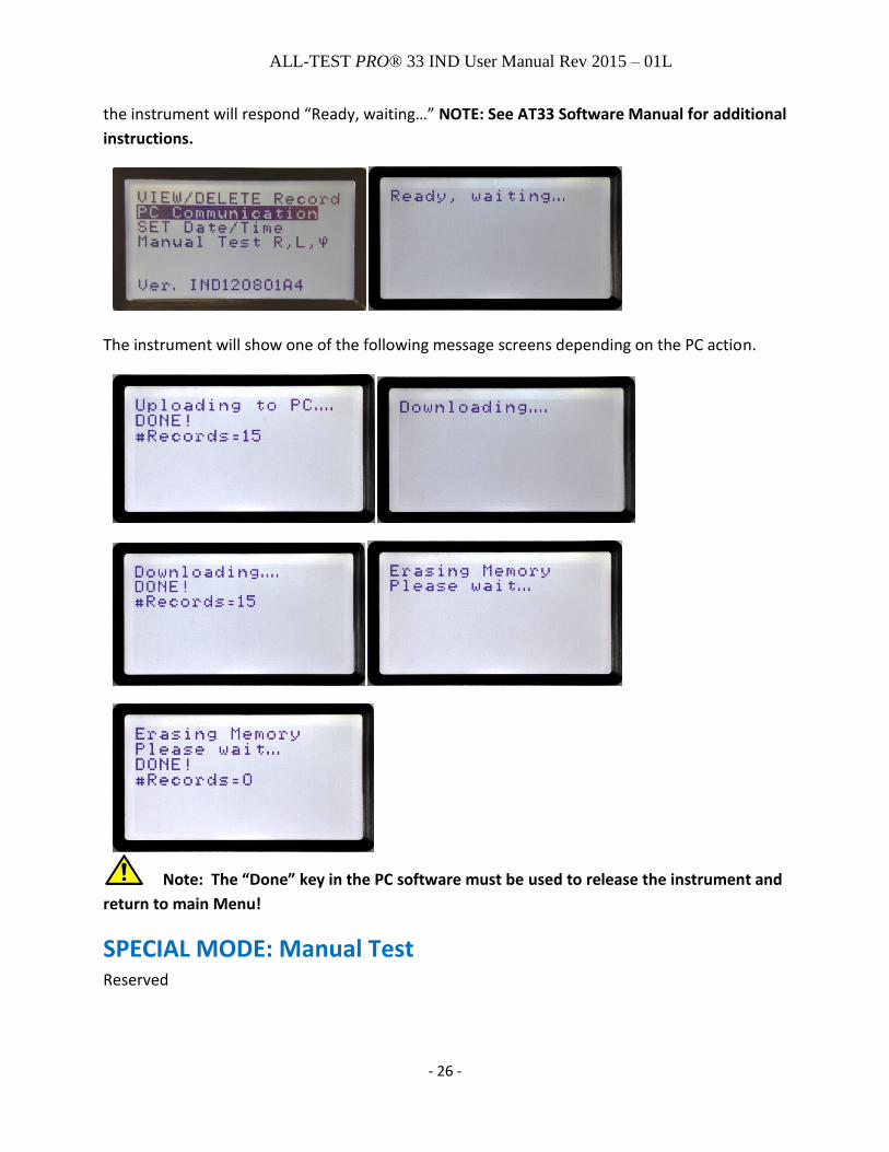
the instrument will respond “Ready, waiting…” NOTE: See AT33 Software Manual for additional
instructions.
The instrument will show one of the following message screens depending on the PC action.
Note: The “Done” key in the PC software must be used to release the instrument and
return to main Menu!
SPECIAL MODE: Manual Test Reserved

ALL-TEST PRO® 33 IND User Manual Rev 2015 – 01L
- 27 -
INSTRUMENT FIRMWARE VERSION Firmware version number is listed after the word Ver.
Note in the image below the firmware version is IND120801A4
ALL-TEST PRO® 33 IND User Manual Rev 2015 – 01L
- 28 -
SPECIFICATIONS Test Frequencies 50, 100, 200, 400, 800 Hz Test Value Static / Reference Value Static 0.01 – 10000 ±1%, (Dimensionless calculated value) Stator Test Dynamic Repeatability ±1%, (of measured data and calculated deviations) Rotor Test Dynamic Repeatability ±2%, (of measured data and calculated deviations) Resistance Resistance 0.01 – 999 Ω measurement range 0.01 – 99.9 Ω ±1%, Max Resolution: 0.01 mΩ 100 Ω - 500 Ω +-1.5%, displayed as whole numbers 501 Ω - 999 Ω +-2.5%, displayed as whole numbers Relative Accuracy “Phase to Phase” ± 0.1% True 4-wire Kelvin measurement. (Compensation for thermoelectric offset voltages) Dissipation factor - DF (frame – stator) 1 – 100% measurement range (expressed as a percentage) 1 – 10% ±0.5 (C = 10 – 1000 nF) 10 – 30% ±1.0 (This specification is based on battery operation and USB not connected to PC) Capacitance (frame – stator) 2 – 2000 nF measurement range 10 – 2000 nF ±5% (This specification is based on battery operation and USB not connected to PC) Insulation Resistance 0 – 999 MΩ @1000V, 0 – 500 MΩ @500V 1 – 100 MΩ ±3%, all other values ±5% Connections 3 x Motor input/output - push-pull connectors 4-pole High Voltage output - Ø 4mm safety jack PC communication - USB type B connector Charger input - 2.5mm diameter center pin DC-jack

ALL-TEST PRO® 33 IND User Manual Rev 2015 – 01L
- 29 -
Keyboard Sealed tactile touch, XL size keys Display Graphic LCD, monochrome 128 x 64 pixels (3.1”), white LED backlight. Temperature range storage -20 °C to +60 °C (-4 °F to +140 °F) Temperature range operating -10 °C to +50 °C (+14 °F to +122 °F) Humidity 0-80% relative humidity, non-condensing Safety According to IEC 61010-1 cat.III 1000V Approvals CE EMC EN61000-6-4 (Emission) EN61000-6-2 (Susceptibility) Calibration Certificate Optional (contact nearest distributor for more information) Batteries 2 x Li-ION cells with ≥ 2100 mAH capacity Enclosure Size 126 x 218 x 51 mm (5” x 8.6” x 2”) (W x L x H) (basic enclosure size without minor protrusions) Material - Polycarbonate, UL94-V2 Weight 0.7 kg (1.55 lb) Accessories (included) 3x Test Leads with Kelvin Clips and push-pull connectors 1x Test Lead with 4mm safety plug and MC “Dolphin” clip Charging adapter, Universal input type 85-260VAC, output 9VDC @ 1.7A Attaché type hard case with pre-cut foam liner User Manual on CD

ALL-TEST PRO® 33 IND User Manual Rev 2015 – 01L
- 30 -
Accessories NOT included Windows XP/7 based software for further analysis, reporting, trending and database storage 1x USB cable 1m Soft carrying pouch for instrument and test leads Specifications subject to change without notice.

ALL-TEST PRO® 33 IND User Manual Rev 2015 – 01L
- 31 -
ADDENDUM A TESTING GUIDE
The AT33IND detects winding contamination, stator faults such as turn-to-turn and coil-to-coil, open
connections, ground faults, and broken/fractured rotor bars. It is optimized to test AC induction motors
with squirrel-cage rotors that operate up to 1000VAC (if your testing application includes motor
operating voltages that exceed 1000V contact us at [email protected] for testing options). It does this
via Static and Dynamic testing processes that only take a few minutes and the instrument will display the
following information:
General Principle
An AC induction motor is a “Symmetric Alternating Current Machine” and when a fault occurs it creates
Asymmetry in the AT33 measured data. All common types of faults in the Rotor and in the Stator
windings breaks the symmetry of the machine (motor), therefore, asymmetry in measuring data
indicates winding and/or rotor fault.
For phase to phase testing, the AT33 outputs a low voltage DC signal and then a sinusoidal signal at
frequencies of 50, 100, 200, 400, & 800Hz. The instrument has four connection leads, of which three are
used to connect to the leads of a three-phase motor and the voltage clips are custom designed Kelvin
clips for improved measurement accuracy. The fourth lead is used for connection to the motor ground or
frame.
Testing Sequence
There are two basic testing modes: Static and Dynamic.
At the end of either test (Static or Dynamic), the user is able to view the results on the instrument’s
display, store the results in the instruments’ memory or upload to a computer for data storage, trending,
and reporting. It is the Dynamic test that provides the OK, Warn, or Bad results for the Stator and Rotor.
The Static test provides the OK, Warn, or Bad for Resistance, Contamination, and Insulation to ground.
Static Test Overview
Static testing starts after the instrument leads have been connected to Phase 2 and Ground (or frame).
An optional Dissipation Factor (DF) test can be done along with a capacitance to ground measurement.
Then the user can perform an optional insulation to ground test. Next the user will connect the

ALL-TEST PRO® 33 IND User Manual Rev 2015 – 01L
- 32 -
remaining two leads and then the instrument will complete the Static test. Static means the test is
performed without moving the rotor.
The testing process is automatic and requires no user interaction once it has been initiated. As part of
this process, the instrument will test all three phases. Resistance and then current, inductance,
impedance, phase angle, current/frequency response, and other measurements are made for all phases.
When complete the user is asked if they want to perform the Dynamic test, if not, then the Static test
results can be viewed, stored, or uploaded to optional computer software.
The Dissipation Factor (DF) is the ratio between the resistive power loss and the reactive power loss of
the insulation material. This is used to detect contaminated or overheated windings.
The insulation to ground test measures resistance of insulation between conductor and ground.
Resistance is measured phase to phase and primary purpose is to detect connection problems.
The Static test provides a number we call “Test Value Static” or TVS and this can be used as either a
reference value or can be compared to a previously stored TVS for comparison purposes.
Static- General Principle
For a Symmetric Alternating Current Machine (motor), the rotor position influences the inductances (L),
impedances (Z), or Phase Angles (Fi) of each stator differently, since the rotor position influences the
coupling of the L, Z, and Fi between stator windings and rotor winding.
However, due to the Symmetry of the motor the measured/calculated Test Value Static (TVS) of the
stator windings is independent of the rotor position. Note: In practice, TVS may be slightly influenced by
the rotor position, due to inaccuracies during assembly of the motor or motor parts (manufacturing
tolerances), slight differences between stator windings, flaws in the rotor, measurement inaccuracies,
etc. (See Figure 1).
All common types of faults in the Rotor and in the Stator windings breaks the symmetry of the motor. As
a result, the TVS will change and no longer be independent of the rotor position. Consequently, a second
TVS will no longer be equal to the first TVS (TVS2 ≠ TVS1).
Static – Testing Sequence
The AT33 outputs a low voltage sinusoidal signal at frequencies of 50, 100, 200, 400, & 800Hz and then
does the following:
Calculates Test Value Static (TVS) in the “first” rotor position. o Rotor position has little influence on TVS value in a good motor.
TVS is a motor specific parameter. o TVS can be used as a Reference (REF) value for detecting fault conditions. o Can be used as a REF value for that specific motor or other motors of exact same type &
manufacturer.
A subsequent test the AT33 calculates a new TVS (at any rotor position).

ALL-TEST PRO® 33 IND User Manual Rev 2015 – 01L
- 33 -
TVS1 is compared to TVS2 . o A change >±3% indicates a change in the condition of the motor (or connections/cables if
testing from the stator or motor drive). Note: Warning alarm of ±3% is based on a well manufactured motor. Poorly made motors or of unusual design may require a higher limit. The actual % deviation of TVS2 compared to TVS1 is displayed in the instruments’ “Compare to REF” function for custom alarm limit applications.
Static- Alarms
RESISTANCE deviation Displayed Result
< 3 % OK
≥ 3% < 5 % WARN
≥ 5 % BAD
No Reading NoR
CONTAMINATION DF%
Displayed Result
≤ 6 % OK
> 6 % ≤ 10 % WARN
> 10 % BAD
No Reading NoR
Dynamic Test Overview
All three phases of the motor are connected to the AT33 and Dynamic testing requires that the user
manually rotate the shaft of the motor while the instrument goes through the testing process. The shaft
is turned in a slow and steady manner without stopping or reversing the rotation. As with the Static test,
the AT33 will test all phases while the shaft is moving and current, inductance, impedance, phase angle,
current/frequency response, and other measurements are made.
It is the Dynamic test that provides the OK, Warn, or Bad results for the Stator and Rotor. Moreover, it
provides the valuable Stator & Rotor Signatures. At the end of Dynamic test results can be viewed,
stored, or uploaded to optional computer software.
Dynamic- General Principle
An AC induction motor is a “Symmetric Alternating Current Machine” and when a fault occurs it creates
Asymmetry in the AT33 measured data. All common types of faults in the Rotor and in the Stator
windings breaks the symmetry of the machine (motor), therefore, asymmetry in measuring data
indicates winding and/or rotor fault.
While the shaft is turned measurements and calculations are made in real-time and without an external
motor shaft position sensor. From these measurements and calculations two important “Signatures” are
presented at the end of the test: Stator and Rotor.
INSULATION MΩ Displayed Result
≥ 20 MΩ OK
≥ 1.5 MΩ < 20 MΩ WARN
< 1.5 MΩ BAD
No Reading NoR

ALL-TEST PRO® 33 IND User Manual Rev 2015 – 01L
- 34 -
Below is how it appears using the computer software (not the same motor as above)
Dynamic Signature Analysis
The Green line is the Stator signature and represents the deviation of the mean values during rotation
for each phase. Note that for Phase 1-3, the Stator signature is slightly elevated above the other two
phases. This indicates the mean values for Phase 1-2 are slightly higher than the other two phases, but
are within acceptable limits and this stator is in good condition.
The two black doted lines represent the Rotor Signature and include an upper and lower signature. This
represents the deviation of the peak values during rotation. As the output of the instrument is
sinusoidal and the response of the motor will be sinusoidal, there will be peak values both positive and
negative. There are 8 dots for each phase and if this were an 8-pole motor then this represents 1 full
revolution of the motor shaft. If this were a 2-pole motor then it represents 4 revolutions of the motor
Each Phase
% Change in Impedance
during rotation
Stator Signature (3 phases)
Rotor Signature Lower
Rotor Signature Upper
Phases (3)
Rotor Upper Signature (3)
Rotor Lower Signature (3)
Stator Signature (3)
Instrument Display
% Change in impedance
during rotation

ALL-TEST PRO® 33 IND User Manual Rev 2015 – 01L
- 35 -
shaft. With this Rotor signature there is a slight variation in the distribution of the peak values, but as
they are within our limit, this rotor is in good condition. The % change in impedance represents the
change in impedance during rotation of the shaft for each phase.
Dynamic Alarms
STATOR signature dev Displayed Result
< 1.1 % OK
≥ 1.1% < 3 % WARN
≥ 3 % BAD
Only STATIC test done use REF (TVS)
Concentric Windings CC
ROTOR signature dev. Displayed Result
< 10 % OK
≥ 10 % < 15 % WARN
≥ 15 % BAD
Only STATIC test done use REF (TVS)
Small Signature Variation With < 2 % variation
< 2
Concentric Windings
A CC warning is an indicator that the difference in the Stator Signature “may” be related to winding
construction. The instrument cannot determine with 100% certainty the type of winding used in the
motors’ construction. Only the motor manufacturer can provide this information.
A stacked winding (concentric wound) may cause asymmetry depending upon construction, therefore,
the reason for the analysis algorithm. With this type of motor construction a Stator Warning may instead
be caused by winding construction, instead of a winding fault.
The Warning level for a Stator fault is set at ≥1.1%, and when a CC warning is shown, and the Stator is in
a Warning condition, then care should be taken before condemning the motor.
Steps to confirm include:
1) Test a known good motor of exact same model and see if the CC warning and alarm appears. a. If CC and Warning appears, then motor is likely good.
2) Contact motor manufacturer to determine winding construction.

ALL-TEST PRO® 33 IND User Manual Rev 2015 – 01L
- 36 -
Figure 1- Test Object 4
RECOMMENDED TESTING PROCEDURE- New Motor
5) Prior to installing the motor a DF/C + Insulation + Static + Dynamic test should be performed
directly at the motor leads and then saved as a reference test.
6) After the motor is installed then an Insulation + Static test should be performed from the
starter/drive and then saved as another reference test. This test should be repeated to verify
stable results are achieved. If erratic results are seen then consult Addendum A for guidelines.
7) Subsequent Insulation + Static testing can be done whether for trouble-shooting or other
purposes. If a change in either the Insulation or Static test is observed then both tests should be
performed at the motor with incoming leads removed from the motor.
8) This new Insulation + Static test at the motor terminals should now be compared to the initial
reference static test that is mentioned in item 1.
a. If the values have not changed from the initial static test then likely the problem is
related to cables/connections between starter/drive and motor.
b. If values have changed from initial static test then the user will need to perform a
complete DF/C + Insulation + Static + Dynamic to determine the root cause for this
change.
Test Value Static (TVS)
Test Object 3- Phases
ALL-TEST PRO® 33 IND User Manual Rev 2015 – 01L
- 37 -
RECOMMENDED TESTING PROCEDURE- Installed Motor
If the motor is performing well then you make an assumption it is in good condition.
Here is a suggested testing process to establish a baseline test for comparison purposes:
1) Perform a Static test only (no Dynamic test) at the output of the starter/motor drive and save the Test Value Static (TVS) as a Reference test (Reference Value Static). Note: skip the DF/Capacitance test but do perform the insulation to ground test.
2) Next go to the motor, remove incoming power leads and perform the Static only test again (no Dynamic test). This TVS will be stored as another Reference Value Static test. Note: perform both the DF/Capacitance and insulation to ground tests.
3) Each installed motor now has two Reference Value Static tests.
When needed, you can perform a new test to be compared to Reference tests previously stored. Useful
whether trouble-shooting a motor system that has quit running, is running poorly, or for PdM purposes.
1) Perform the new Static test from the output of the starter/motor drive. 2) If the new TVS has changed >3% from the Reference Value Static this indicates a change in
condition of the motor system. I.e. connections, cables, or the motor itself. 3) In order to determine where the change has occurred you need to test at the motor with leads
removed. Then compare this new test to the Reference test previously stored (stored test with the power leads removed).
This will provide information regarding if the change in condition is connection/cable related or motor
related.
Misc
1) Instrument will power off after approximately five minutes of inactivity. 2) If one motor phase is open the AT33 will state “no connection” and will ask you if you want to
“OK to skip” to the next phase in order to complete the test. If the connection between the motor and AT33 is correct then you can press “OK” and it will sequence to the next phase (if on last phase then it will complete the Static test).
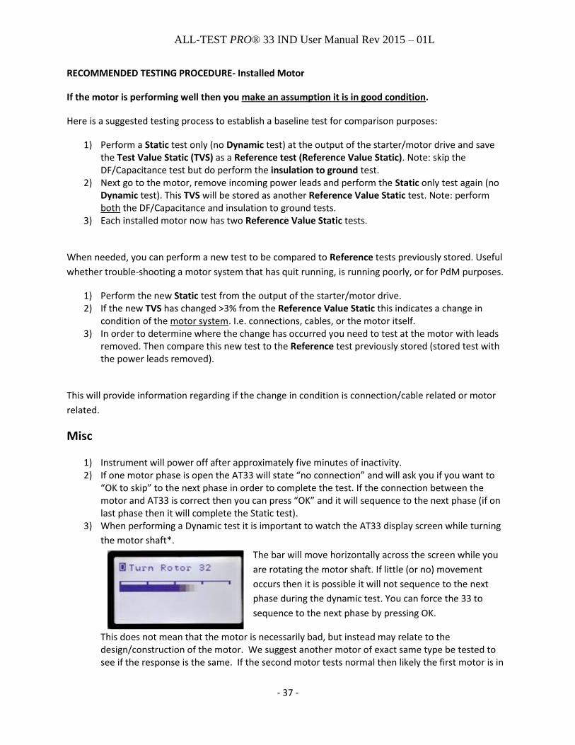
3) When performing a Dynamic test it is important to watch the AT33 display screen while turning
the motor shaft*.
The bar will move horizontally across the screen while you
are rotating the motor shaft. If little (or no) movement
occurs then it is possible it will not sequence to the next
phase during the dynamic test. You can force the 33 to
sequence to the next phase by pressing OK.
This does not mean that the motor is necessarily bad, but instead may relate to the design/construction of the motor. We suggest another motor of exact same type be tested to see if the response is the same. If the second motor tests normal then likely the first motor is in

ALL-TEST PRO® 33 IND User Manual Rev 2015 – 01L
- 38 -
suspect condition. If it tests just like the first motor then contact us for other testing options. Email your technical support questions to [email protected] . *How long to turn the shaft for each phase will vary by motor, but typically should not exceed 30 seconds per phase. If it does take more than 30 seconds then press OK to sequence to the next phase. If the next phase tests like the previous one then see item 2 above.
4) Connecting the AT33 Kelvin clips to small connection points a. When making a connection to a point that is much smaller than the jaw face, we
recommend that only a portion of the jaw make contact. i. Connecting using just the front portion of the jaws as seen here
ii. Connecting using one side of the jaws as seen here
5) Non-repeatable test results should be considered to be suspect. There may be external sources
causing non-repeatable results. Contact [email protected] for more information. 6) Never condemn a motor from the Motor Control Center. Faults in the cabling or connections
between the test point and the motor itself can cause a fault indication. Before condemning a motor always perform a confirming test at the motor with the motor leads disconnected from the supply cabling.
7) Dissipation Factor and Capacitance testing- Erratic readings b. If a beep is heard during the C & DF test this indicates a problem with the measurement.
Test should be repeated, if beep is heard again then something is interfering with testing process. Connection, external interference, etc.
c. Any leads not used for the C/DF test that are connected to the motor phase terminals
can act as antennas and couple interference to the sensitive high impedance node.
Solution: Only use the Blue and Yellow test leads connected to motor terminals during C
and DF test.
d. The motor/test set-up could be in closer than normal proximity to a single interference
source like fluorescent light, frequency inverter, cell phone, etc. Solution: Disconnect
power temporarily to suspected interference source if possible. Move test object or EMI
source. Test again at a later time to see if EMI is lower.

ALL-TEST PRO® 33 IND User Manual Rev 2015 – 01L
- 39 -
e. The general interference levels of the site at large could surpass the limits for “Heavy
Industrial Environment” according to CE testing. Solution: Disconnect power temporarily
to suspected interference source(s) if possible. Move test object. Test again at a later
time to see if EMI is lower.
8) Insulation to Ground Recommended Test Voltage & Minimum Insulation Test Values (from IEEE
Std. 43)
NOTE: The IEEE guidelines above provide the recommended voltages and Minimum Insulation
Resistance to ground values. If these procedures or values differ from your equipment
manufactures’ recommendations, follow their guideline.
According to IEEE Std 43, the insulation resistance is measured after applying DC high voltage for 1
minute. The motor should be above dew point temperature before testing if possible. It is important to
correct values to a reference temperature (typically 40 °C) so that trends and changes in insulation
resistance can be readily detected. Contamination, humidity, temperature, and other factors affect
insulation resistance values.
The standard recommends choosing test voltages for insulation resistance testing:
The standard also recommends minimum insulation resistance value at 40 oC as shown below. “kV” is
the rated line to line rms voltage of 3 phase motor, line to ground voltage of single phase motor, or rated
DC motor voltage.

ALL-TEST PRO® 33 IND User Manual Rev 2015 – 01L
- 40 -
Disclaimer, Copyright & Trademarks Notice of Service/Trademark Rights
The trademarks, service marks and logos (collectively, the "Marks") set forth below are
registered and unregistered trademarks and/or service marks owned by ALL-TEST Pro, LLC in the
United States and certain other countries throughout the world. Nothing contained in this
manual should be construed as granting, by implication, estoppels or otherwise, any license or
right to use any of the Marks without the written permission of ALL-TEST Pro, LLC. Any misuse of
the Marks or any Content, except as provided in this Statement, is strictly prohibited and may
violate trademark laws.
Other brands or product names used in this manual are trademarks and/or service marks of
their respective owners, should be treated as such, and may be registered in various
jurisdictions.
1) ALL-TEST PRO® is a Registered Trademark of ALL-TEST Pro, LLC 2) EMCAT PRO®, ALL-TEST PRO®, ALL-TEST IV PRO™, TREND™, AT33IND™,
AT33EV™ are all Trademarks of ALL-TEST Pro, LLC
Disclaimer:
Documents published by ALL-TEST Pro, LLC are provided "as is" without warranty of any kind, either expressed, implied or statutory, including, but not limited to any warranties of merchantability, fitness for a particular purpose, or non-infringement.
ALL-TEST Pro, LLC shall not under any circumstances be liable to any person for any special, incidental, indirect or consequential damages, including, without limitation damages resulting from use of or reliance on the information presented, loss of profits or revenues or costs of replacement goods, even if informed in advance of the possibility of such damages.
Reasonable efforts have been made to ensure the accuracy of the information presented. However, ALL-TEST Pro, LLC assumes no responsibility for the accuracy of the information. Product information is subject to change without notice. ALL-TEST Pro, LLC may make improvements and/or changes in the products and/or the programs described in these publications at any time without notice.
Information in this document is: © 2011-2013, ALL-TEST Pro, LLC All Rights Reserved
You may cite or refer to information published in this manual, except as provided below, but you may not reproduce or distribute such information in whole or in part without the prior written permission of ALL-TEST Pro, LLC. You may not reproduce or distribute any image from the Manual, without securing advance written consent from ALL-TEST Pro, LLC. To request such permission, send email to [email protected], including your name, address and a description of the purpose of your intended distribution and the information you would like to distribute.

ALL-TEST PRO® 33 IND User Manual Rev 2015 – 01L
- 41 -
You may print, reproduce and use the information in, and retrieve files containing software or images from ALL-TEST Pro, LLC for non-commercial, personal, or educational purposes only, provided that you (i) do not modify such information, and (ii) include any copyright originally included with such information and this notice in all such copies.
Nothing contained herein shall be construed as conferring by implication or otherwise any license or right under any patent or trademark of ALL-TEST Pro, LLC or any third party. No other rights under any copyrights of ALL-TEST Pro, LLC or any other party are granted herein, except as expressly stated above.