user manual dns-1250-04 and dns-1250-06 nas systems
TRANSCRIPT

User Manual
DNS-1250-04 and DNS-1250-06
NAS Systems
© 2011 D-Link, Inc. All Rights Reserved.

ii
Contents Chapter 1: Introduction.......................................................................... 1
1.1 About This Manual ........................................................................1
1.2 Protocol Support ...........................................................................2
1.3 Hardware Specifications ...............................................................2
1.4 Client Utility OS Support ...............................................................3
1.5 Browser Support ...........................................................................3
Chapter 2: Quick Setup.......................................................................... 5
2.1 Verifying Package Contents..........................................................5
2.2 Installing Physical Drives ..............................................................8
2.3 Connecting the Ethernet Cable...................................................10
2.4 Connecting the Power ................................................................10
2.5 Network Configuration with the LCD Screen .............................. 11
2.6 Configuration...............................................................................12
2.6.1 Connecting to ShareCenter Pro.....................................12
2.6.2 Choosing a Display Language.......................................13
2.7 Setup Wizard ..............................................................................13
2.7.1 Using the One-Click Setup Wizard ................................13
2.7.2 Using Advanced Configuration Wizard ..........................14
2.8 Shutting Down the NAS System.................................................15
Chapter 3: ShareCenter Pro Configuration Manager ....................... 16
3.1 Browser Support .........................................................................16
3.2 Connecting to ShareCenter Pro..................................................16
3.3 Choosing a Display Language....................................................17
3.4 Navigating in ShareCenter Pro ...................................................17
3.5 Dashboard Tab............................................................................18
3.5.1 System Status ................................................................18
3.5.2 Event Information...........................................................19
3.5.3 Storage Overview...........................................................19
3.6 Device Tab ..................................................................................19
3.6.1 Front View ......................................................................19

iii
Identifying Unconfigured Physical Drives ...........................20
Identifying Physical Drives Assigned to a Disk Array .........20
3.6.2 Back View ......................................................................20
3.6.3 Component List ..............................................................21
Enclosure............................................................................21
Controller ............................................................................21
Buzzer.................................................................................23
LED.....................................................................................24
3.6.4 Physical Drives...............................................................24
View List of Physical Drives................................................24
View Physical Drive Information .........................................25
Global Physical Drive Settings ...........................................25
Individual Physical Drive Settings.......................................26
Physical Drive Problems.....................................................26
3.6.5 iSCSI ..............................................................................27
View iSCSI Information.......................................................27
Setting up a CHAP..............................................................27
3.6.6 Network ..........................................................................28
Basic Network Settings.......................................................28
Changing Networking Configuration...................................28
Advanced Networking Configuration ..................................29
Setting up a DHCP Server..................................................29
Setting up DDNS ................................................................29
3.6.7 UPS................................................................................30
View UPS Information.........................................................30
Setting up a UPS ................................................................30
3.6.8 External USB Drive ........................................................31
External Drive Information ..................................................31
Configuring an External Drive.............................................31
Formatting an External Drive..............................................31
Removing an External Drive ...............................................33
3.7 Storage Tab.................................................................................33
3.7.1 Creating a Disk Array .....................................................33

iv
3.7.2 Creating a Logical Drive.................................................35
Initializing a Disk Array........................................................36
3.7.3 Disk Array Problems ......................................................36
Disk Array Degraded...........................................................37
Disk Array Offline ................................................................37
3.7.4 Disk Array Management.................................................37
Locating a Disk Array..........................................................39
Deleting a Disk Array ..........................................................39
3.7.5 Logical Drive Management ............................................40
Logical Drive Information ....................................................40
Logical Drive Settings .........................................................41
Logical Drive Check Tables ................................................41
Locating a Logical Drive .....................................................42
Deleting a Logical Drive......................................................44
Redundancy Check ............................................................44
Synchronization Settings ....................................................45
3.7.6 Logical Drive Problems ..................................................45
3.7.7 Spare Drive Management ..............................................46
Spare Drive Information ......................................................46
Assigning a Spare Drive .....................................................47
3.8 AdminTool Tab ............................................................................47
3.8.1 NAS Subsystem Management.......................................48
Viewing NAS System Information.......................................48
Making NAS System Settings.............................................48
3.8.2 NAS System Shutdown and Restart ..............................49
3.8.3 Clearing Subsystem Statistics........................................49
3.8.4 Software Service Management......................................49
Starting a Software Service ................................................49
Making Software Service Settings ......................................50
3.8.5 Runtime and NVRAM Event Logs..................................50
Viewing Runtime Events.....................................................50
Viewing NVRAM Events .....................................................51
Clearing Events...................................................................51

v
Saving Events.....................................................................52
3.8.6 Background Activity........................................................52
Media Patrol........................................................................52
Redundancy Check ............................................................53
Rebuild................................................................................53
Migration .............................................................................53
PDM....................................................................................54
Transition ............................................................................55
Running a Background Activity ...........................................55
Scheduling a Background Activity ......................................56
Viewing a List of Scheduled Background Activities ............57
Changing a Scheduled Background Activity.......................57
3.8.8 Firmware Updates..........................................................58
3.8.9 Performance Monitor .....................................................59
Monitored Components ......................................................59
Viewing Logical Drive Performance....................................59
Viewing Physical Drive Performance..................................59
Viewing Port Performance ..................................................60
3.8.10 Restore Factory Default Settings ...................................60
3.8.11 System Configuration Files ............................................61
Importing a System Configuration File ...............................61
Exporting a System Configuration File ...............................61
3.8.12 LUNMap Management...................................................61
Adding an Initiator...............................................................61
Defining LUN Mapping........................................................62
3.8.13 Power Option .................................................................62
3.8.14 Message Alerts...............................................................63
Setting-up Email Alert Service ............................................63
Adding an E-Mail Account...................................................64
Editing an E-Mail Account...................................................64
Deleting an E-Mail Account.................................................64
3.8.15 Network Security ............................................................65
Setting-up a Security Policy................................................65

vi
Setting-up Access Protection..............................................65
Setting-up an SSL Certificate .............................................66
3.9 NAS Tab......................................................................................66
3.9.1 Setup Wizard..................................................................66
Using the Automatic Configuration Wizard .........................66
Using the Advanced Configuration Wizard .........................67
3.9.2 User Account Management............................................68
Adding Users ......................................................................68
Editing User Information .....................................................68
Deleting Users ....................................................................69
Adding a Group of Users ....................................................69
Adding and Removing Users from a Group........................70
Making User and Group Permission Settings.....................70
Deleting a Group of Users ..................................................70
3.9.3 Protocol Control and Setting ..........................................71
3.9.4 File System Management ..............................................71
Viewing File System Information ........................................71
Setting a File System Quota ...............................................72
Deleting a File System........................................................72
3.9.5 File Sharing Management..............................................72
Creating an ISO Folder.......................................................72
Making ISO Folder Settings................................................73
Creating a Folder ................................................................73
Changing Folder Settings ...................................................74
Setting up Folder Sharing ...................................................74
3.9.6 Backup Management .....................................................77
Choosing a Backup Solution ..............................................77
Setting up Snapshot Backup ..............................................78
Changing Snapshot Backup Schedule Settings .................78
Deleting a Snapshot Backup Schedule ..............................79
Performing a Remote Backup.............................................79
Local Backup ......................................................................81
Enabling One-Touch Backup ..............................................81

vii
Amazon S3 Backup ............................................................82
3.9.7 Plug-in Management......................................................84
3.9.8 iSCSI Initiator Management ...........................................85
Chapter 4: ShareCenterNAVI............................................................... 86
4.1 Working with ShareCenterNAVI..................................................86
4.1.1 Opening the Main Window.............................................86
4.1.2 Choosing a Display Language.......................................87
4.1.3 Starting ShareCenter Pro...............................................88
Main Window ......................................................................88
4.1.4 ShareCenterNAVI Information .......................................88
Viewing ShareCenterNAVI on Windows.............................88
Viewing ShareCenterNAVI on Mac.....................................89
4.1.5 Closing ShareCenterNAVI .............................................89
Alternative Method for Windows.........................................90
4.2 Managing Backups .....................................................................90
4.2.1 Doing a Backup Now .....................................................90
Main Window ......................................................................91
Device List ..........................................................................91
Tray Icon .............................................................................92
4.2.2 Scheduling a Backup .....................................................93
4.2.3 Viewing Backup Schedules............................................94
4.2.4 Changing a Scheduled Backup......................................94
4.2.5 Deleting a Scheduled Backup........................................95
4.2.6 Restoring Backed-up Files.............................................96
4.2.7 Viewing the Backup Event Log ......................................97
4.2.8 Saving the Event Log.....................................................98
Saving the Backup Event Log ............................................98
4.2.9 Clearing the Event Log ..................................................99
4.2.10 Setting the Port ..............................................................99
4.3 Managing Share Folders ..........................................................100
4.3.1 Opening a Share Folder...............................................100
Device List ........................................................................100

viii
Main Window ....................................................................100
Tray Icon ...........................................................................100
4.3.2 Viewing a List of Share Folders ...................................101
4.3.3 Mounting a Share Folder / Creating a Network Drive..101
4.3.4 Un-mounting a Share Folder / Disconnecting a Network Drive.............................................................................101
4.3.5 Setting up a Share Folder for Time Machine ...............102
In ShareCenterNAVI .........................................................102
On the Mac, Time Machine NOT configured ....................103
On the Mac, Time Machine Configured ............................103
4.4 Making Management Settings ..................................................104
4.4.1 Configuring a NAS System ..........................................104
One Click Setup................................................................104
Advanced Setup ...............................................................105
4.4.2 Locating the NAS system.............................................106
4.4.3 Wake-on-LAN...............................................................108
4.4.4 Choosing a Default NAS System.................................108
Setting the default NAS ....................................................108
4.4.5 Viewing the System Event Log ....................................109
4.4.6 Installing Plug-ins ......................................................... 110
4.4.7 Viewing a List of Plug-ins............................................. 110
4.4.8 Viewing Plug-in Version Numbers................................ 110
4.4.9 Enabling and Disabling Plug-ins .................................. 111
Enabling Plug-ins.............................................................. 111
Disabling Plug-ins ............................................................. 112
4.4.10 Removing Plug-ins....................................................... 112
Removing Plug-ins............................................................ 112
4.4.11 Rebooting the NAS System ......................................... 113
4.4.12 Shutting Down the NAS system................................... 114
Chapter 5: Licensing and Support ................................................... 116
GNU General Public License ............................................................. 116
Technical Support............................................................................... 116

Chapter 1: Introduction
1.1 About This Manual This User Manual describes how to setup, use, and maintain the DNS-1250-04 and DNS-1250-06 NAS systems. It also describes how to use:
ShareCenterNAVI software that you install and run on your PC
ShareCenter Pro configuration manager software that runs on the NAS
systems by browser.
This manual includes a full table of contents, chapter task lists, and numerous cross-references to help you find the specific information you are looking for.
Also included are four levels of notices:
Note
A Note provides helpful information such as hints or alternative ways of doing a task.
Important
An Important calls attention to an essential step or point required to complete a task. Important items include things often missed.
Caution
A Caution informs you of possible equipment damage or loss of data and how to avoid them.
Warning
A Warning notifies you of probable equipment damage or loss of data, or the possibility of physical injury, and how to avoid them.
1

2
1.2 Protocol Support DNS-1250-04 and DNS-1250-06 NAS systems support:
SMB/CIFS for Microsoft Windows
NFS for Linux/Unix
AFP for Mac OS
FTP
WebDAV for the file transform over the Internet
iSCSI Target model and Initiator model
1.3 Hardware Specifications
CPU 1.8 GHz
FLASH 256 MB
SDRAM 2GB DDRII
Smart Fan Yes
Gigabit Ethernet port 2
USB 2.0 Host port 5 (Front x 1/ Back x 4)
LCD Display Yes
Internal HDD Support 3.5" 3-Gb/s SATAII
Hot Plug Yes
# of Bays 4 (DNS-1250-04)/ 6 (DNS-1250-06)
Power Supply 250W (80 PLUS)
DNS-1250-06 243(L)*188(W) *251(H) mm 9.56(L)*7.40(W)*9.88(H) in
Dimensions
DNS-1250-04 243(L)*188(W) *191(H) mm 9.56(L)*7.40(W)*7.52H) in
For more information, visit the D-Link website at http://www.dlink.com/.

1.4 Client Utility OS Support The following operating systems support ShareCenterNAVI:
Windows XP 32/64 Bit
Windows Vista 32/64 Bit
Windows Server 2003 32/64 Bit
Windows Server 2008 32/64 Bit
Windows Server 2008 R2
Windows 7 32/64 Bit
Mac OS 10.5 and above
Mac OS 10.6 XServer
1.5 Browser Support Choose one of the following browsers to use with the ShareCenter Pro configuration manager:
Internet Explorer 7 and above
Firefox 3 and above
Safari 5 and above
Google Chrome 8 and above
Warning
The electronic components within the NAS system are sensitive to damage from Electro-Static Discharge (ESD). Observe appropriate precautions at all times when handling the NAS system or its subassemblies.
3
Warning
The fan contains hazardous moving parts. Keep fingers away.
Caution
Risk of explosion if the battery is replaced by an incorrect type.
Important
To configure the NAS system, you are advised to install ShareCenterNAVI. Please refer to the User’s Manual.
4

Chapter 2: Quick Setup
2.1 Verifying Package Contents Open the shipping carton for the DNS-1250-04 or DNS-1250-06 and carefully remove and unwrap its contents.
D-Link DNS-1250-04 or DNS-1250-06
CD-ROM with Manual and Software
Quick Installation Guide
Power Cord
Ethernet Cable
Screws for Physical drive installation
If any of the above items are missing, please contact your reseller.
Figure 1. DNS-1250-04 Front View
The DNS-1250-06 is similar.
USB Connector
LCD One-Touch
Backup Button
Ethernet Status LED
Select Button Enter Button
Disk Carrier Disk Status LED
Disk Activity LED
Power Button / System Status
5

6
Item Function Description
Ethernet Status LED Green: Network active at 1000 Mb/s Orange: Network active at 100 Mb/s
Disk Status LED
Green: Drive is healthy Orange: Disk is rebuilding Red: Disk error Flashing Green: Physical drive locate feature
Disk Activity LED Flashing Green: Disk activity
System Status LED
Green: System is healthy Orange: Disk array degraded Red: Disk array offline or Enclosure error Flashing Red > Orange > Green: Power on
One-Touch Backup Button
Enables one-touch backup. Flashes blue while backup is processing
Power Button Power on / power off

Figure 2. DNS-1250-04 Rear View
The DNS-1250-06 is similar.
System Cooling Fan
Power Connector
USB Connectors (4)
RJ45 Network Connectors (2)
VGA Connector
Item Description
USB Connectors For USB printer and flash drive backup
RJ45 Network Connectors
For Ethernet cable connection
VGA Connector Video output connection
Power Connection Power cord connection
7
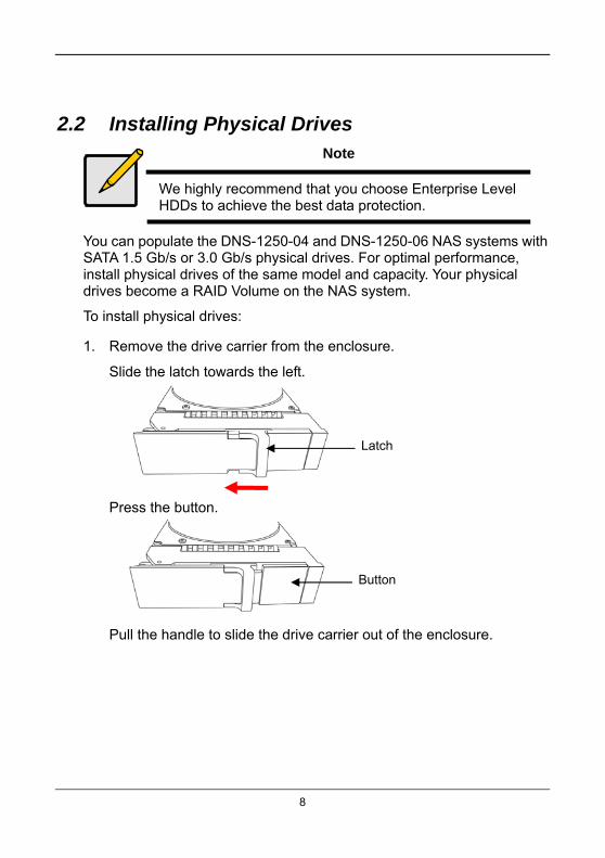
2.2 Installing Physical Drives Note
We highly recommend that you choose Enterprise Level HDDs to achieve the best data protection.
You can populate the DNS-1250-04 and DNS-1250-06 NAS systems with SATA 1.5 Gb/s or 3.0 Gb/s physical drives. For optimal performance, install physical drives of the same model and capacity. Your physical drives become a RAID Volume on the NAS system.
To install physical drives:
1. Remove the drive carrier from the enclosure.
Slide the latch towards the left.
Latch
Press the button.
Button
Pull the handle to slide the drive carrier out of the enclosure.
8

Handle
2. Carefully lay the physical drive into the drive carrier and align the
screw holes of the drive and carrier.
Physical drive
Physical drive power and data connector
3. Insert the screws through the holes in the drive carrier and into the
sides of the physical drive.
Install only the counter-sunk screws supplied with the NAS
system.
Install four screws per drive.
Snug each screw. Be careful not to over-tighten.
9

Drive carrier Physical drive
Screwdriver
Mounting screw
4. Reinstall the drive carrier into the enclosure.
5. Repeat steps 1 through 4 until all of your physical drives are installed.
Caution
To avoid hand contact with an electrical hazard, remove only one drive carrier a time.
2.3 Connecting the Ethernet Cable To connect the NAS system to your network:
1. Attach one end of the network cable to an RJ45 network connector.
RJ45 Network Connectors (2)
2. Attach the other end of the network cable to your Ethernet hub or
switch.
2.4 Connecting the Power To connect and power up the NAS system:
1. Attach the power cord on the back of the enclosure.
10
2. Plug the other end into your power source.

Power Connector
3. On the front of the NAS system, press the Power Button.
Power Button /System Status
It takes about a minute to boot up. When fully booted:
The System Status LED turns blue.
The buzzer beeps one time.
2.5 Network Configuration with the LCD Screen The DNS-1250-04 and DNS-1250-06 NAS systems have an LCD screen on the front panel that enables you to monitor system status and configure the network.
Select button
Enter button
To configure the networking settings:
1. Press the Enter button to display the Network Setup option.
2. Press the Select button to choose each option.
3. Then press the Enter button to change the setting values.
11
4. When you are done, choose OK and press the Enter button to apply
the networking configuration.
2.6 Configuration
2.6.1 Connecting to ShareCenter Pro
To connect with the ShareCenter Pro configuration manager over your network:
1. Start your browser.
2. In the URL field, enter the default IP address http://192.168.0.32.
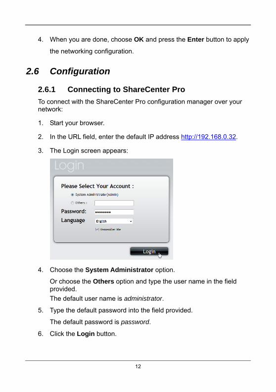
3. The Login screen appears:
4. Choose the System Administrator option.
Or choose the Others option and type the user name in the field provided.
The default user name is administrator.
5. Type the default password into the field provided.
The default password is password.
6. Click the Login button.
12

13
2.6.2 Choosing a Display Language
ShareCenter Pro displays in English, Russian, Spanish, French, German, Italian, Japanese, Korean, Simplified Chinese, and Traditional Chinese.
Choose the display language from the dropdown menu when you log in.
If you have already logged in:
1. Click the Logout button at the top right corner of the ShareCenter
Pro window.
The Login screen appears.
2. From the language dropdown menu, choose the display language
you want.
3. Click the Login button to log into ShareCenter Pro again.
2.7 Setup Wizard The Setup Wizard configures your disk arrays easily and quickly. To configure automatically, use One-Click Setup. To configure manually, use Advance Setup.
2.7.1 Using the One-Click Setup Wizard
To configure your disk arrays with the One-Click Setup Wizard:
1. Click the NAS tab.
2. Click the One-Click Setup button.
The Summary box displays the proposed system configuration.
Computer Name – Input a new name, if desired
IP Address – Shows the IP address assigned by your DHCP
server
Storage Type – Data Protection by default
14
3. To accept the proposed configuration, click the Submit button.
If you disagree with the proposed configuration, click the Advanced Setup button to specify your settings manually.
2.7.2 Using Advanced Configuration Wizard
To configure your disk arrays with the Advanced Setup Wizard:
1. Click the NAS tab.
2. Click the Advanced Setup button.
3. Make the following network settings as required.
Computer Name – Input a new name, if desired
Member of – Check the box to let your enable DHCP make the
network settings
4. If you did not check the Member of box, input your settings in the
fields provided,
IP Address
Subnet Mask
Default Gateway
Primary DNS
Secondary DNS
When you are finished, click the Next button.
5. Choose the file system option you want.
Data Protection – Uses part of the physical drive space for
redundancy
Maximum Capacity – Uses all physical drive space for data only
When you are finished, click the Next button.
6. Review the proposed configuration and click the Submit button.
If you disagree with the proposed configuration, click the Back button to change your settings.
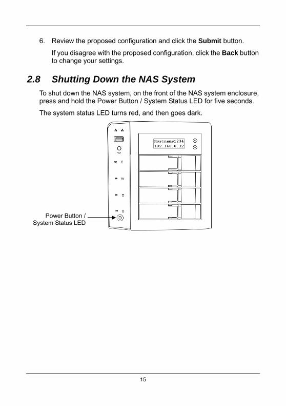
2.8 Shutting Down the NAS System To shut down the NAS system, on the front of the NAS system enclosure, press and hold the Power Button / System Status LED for five seconds.
The system status LED turns red, and then goes dark.
Power Button /System Status LED
15
Chapter 3: ShareCenter Pro Configuration Manager
The ShareCenter Pro Configuration Manager is factory-installed on the DNS-1250-04 and DNS-1250-06 NAS systems. ShareCenter Pro runs in the browser on your PC or Mac. You can access ShareCenter Pro by browser.
3.1 Browser Support Choose one of the following browsers to use with ShareCenter Pro:
Internet Explorer 7 or above
Firefox 3 and above
Safari 5 and above
Google Chrome
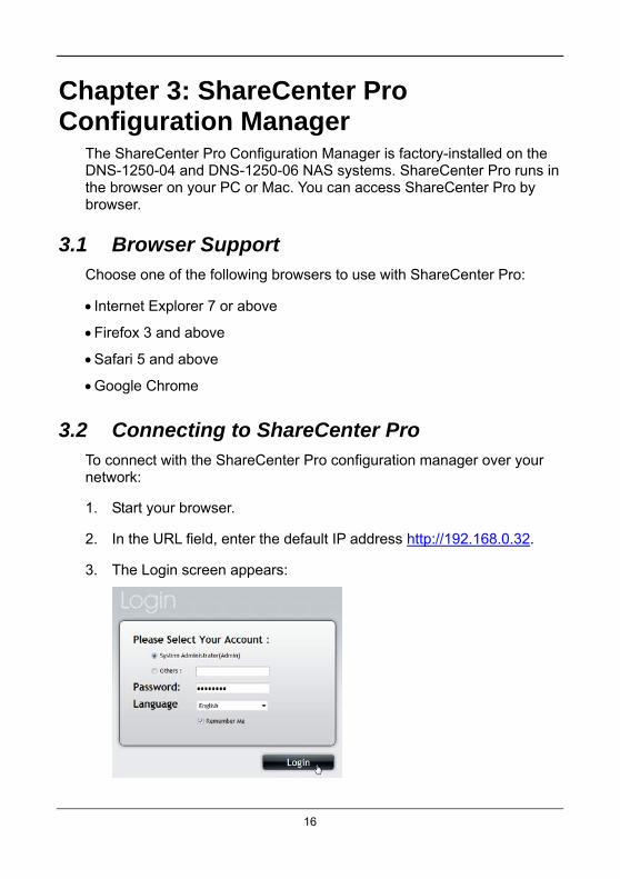
3.2 Connecting to ShareCenter Pro To connect with the ShareCenter Pro configuration manager over your network:
1. Start your browser.
2. In the URL field, enter the default IP address http://192.168.0.32.
16
3. The Login screen appears:

17
4. Choose the System Administrator option.
Or choose the Others option and type the user name in the field provided.
The default user name is administrator.
5. Type the default password into the field provided.
The default password is password.
6. Click the Login button.
3.3 Choosing a Display Language ShareCenter Pro displays in English, Russian, Spanish, French, German, Italian, Japanese, Korean, Simplified Chinese, and Traditional Chinese.
Choose the display language from the dropdown menu when you log in.
If you have already logged in:
1. Click the Logout button at the top right corner of the ShareCenter
Pro window.
The Login screen appears.
2. From the Language dropdown menu, choose the display language
you want.
3. Click the Login button to log into ShareCenter Pro again.
3.4 Navigating in ShareCenter Pro The five tabs displayed on the screen are the primary navigation tool in ShareCenter Pro. Categories of functions listed under their icons.
Icons for specific functions are listed above the tabs. Click the tab to view the functions.
Click the function icons to display their information on the screen. Each function has one or more tabs in its screen.

3.5 Dashboard Tab The Dashboard tab is the default screen of ShareCenter Pro.
The System Status icon indicates the top-level status of NAS system by displaying:
The system is OK.
The system has errors.
3.5.1 System Status
The System Status field displays the high-level of the NAS components by the following status icons:
The component is OK.
The component needs attention.
The component has failed.
Click the component name to view more information.
18

19
3.5.2 Event Information
The Event Information field displays six of the most recent Runtime events.
Click the More link to display the Runtime Events screen.
Click the NVRAM Events button to view the NVRAM events.
Click the Runtime Events button to return to Runtime events
3.5.3 Storage Overview
The Storage Overview field displays the general information of the current storage status, including:
Total Physical Capacity – Displays the total storage capacity of the NAS
system.
Unconfigured – Not assigned to a logical drive.
Configured – Assigned to a logical drive.
Device Number – Displays the current number of devices in the system.
3.6 Device Tab The Device tab displays the information of all device status of the NAS, including physical drives, disk arrays, logical drives, power supply units, blowers, and backplanes.
In the Device tab, you can make settings for the enclosure and physical drives.
3.6.1 Front View
Click the Front View button to view of the NAS enclosure. Mouse-over the drive carrier to display the information of the physical drive:
Device ID
Physical capacity
Operational status

20
Configuration – Array number and sequence number
Identifying Unconfigured Physical Drives
Check the Show unconfigured PD(s) box to identify the unconfigured physical drives in the NAS.
Identifying Physical Drives Assigned to a Disk Array
Click the Highlight Arrays button to identify the physical drives assigned to a disk array.
Click the following items in the dropdown menu:
All DA – all disk arrays
DA0 (DA1, DA2, etc.) – a specific disk array
Close – click to close the menu and return to normal view.
The carriers containing drives that do not belong to the chosen disk array are highlighted.
3.6.2 Back View
Click the Back View button to display the back view of all enclosures in the NAS. Mouse-over the power supply and I/O units to view the PSU status and the operational status of the devices through the I/O units. Click Show Internal Components to display the virtual view of the internal components (see below).
Mouse-over the component and the related information will be displayed:
CPU – CPU usage
Controller thermometer – temperature of the controller board
Temperature of the system
RAM – memory usage
Enclosure information
21
3.6.3 Component List
Click the Component List button to display the device ID, operational status, enclosure type, and status description of all enclosures.
Enclosure
To view enclosure information, mouse-over the enclosure you want and click the View button.
To make enclosure settings, mouse-over the enclosure you want and click the Settings button. Set the controller warning and controller critical temperatures.
To locate the enclosure, mouse-over the enclosure you want and click the Locate button. The buzzer sounds to help you identify the NAS system.
Controller
To view controller information, mouse-over the controller and click the View button.

22
To make controller settings:
1. Mouse-over the controller and click the Settings button.
2. Make setting changes as required.
Enter, change or delete the alias in the Alias field
Enable SMART Log – Check the box to enable or uncheck to
disable
SMART Polling Interval – Enter a value into the field, 1 to 1440
minutes
HDD Power Levels – Choose time periods from the dropdown
menus.
Level 0: Disabled
Level 1: Park the read/write heads
Level 2: Lowers disk rotation speed
Level 3: Spins down the disk (stops rotation)
Coercion – Check the box to enable or uncheck to disable.
This feature is designed for fault-tolerant logical drives (RAID 1, 1E, 5, 10, 50, and 60). It is generally recommended to use physical drives of the same size in your disk arrays. When this is not possible, the system adjusts for the size differences by reducing or coercing the capacity of the larger drives to match the smaller ones.
Coercion Method – Choose a method from the dropdown menu:
GB Truncate – Default. Reduce the useful capacity to the
nearest 1,000,000,000 byte boundary.

23
10GB Truncate – Reduces the useful capacity to the nearest
10,000,000,000 byte boundary.
Group Rounding – Uses an algorithm to determine how
much to truncate. Results in the maximum amount of usable
drive capacity.
Table Rounding – Applies a predefined table to determine
how much to truncate.
Write Back Cache Flush Interval – Enter a value into the field, 1 to
12 seconds
Physical Drive Temperature Threshold
Enclosure Polling Interval
Adaptive Writeback Cache
UPS power good: write back
UPS power fail: write through
No UPS: write through
Host Cache Flushing
Forced Read Ahead (cache) – Check the box to enable or
uncheck to disable
3. Click the Save button.
Buzzer
To mute the buzzer, click the Mute button.
To unmute the buzzer, click the Sound button.
To make buzzer settings:
1. Mouse-over the buzzer and click the Settings button.
24
2. Make setting changes as required.
3. Check the Enable Buzzer option to enable the buzzer for all events.
Uncheck to disable.
4. Click the Save button.
LED
This setting enables you to turn the enclosure LEDs ON and OFF.
To make LED settings:
1. Mouse-over the buzzer and click the Settings button.
2. Choose an LED setting:
Always ON
Always OFF
Daily
3. Click the Save button.
3.6.4 Physical Drives
View List of Physical Drives
To view a list of physical drives:
1. Click the Device tab.
2. Click the Physical Drive button.
Physical drive information includes,
ID – ID number of the physical drive
Status – Green, yellow, and red icons
Model – Make and model of the drive
Type – SATA HDD

Location – Enclosure number and slot number
Configuration – Array number and sequence number, spare
number, unconfigured, or stale configuration
Capacity – The capacity of drive
View Physical Drive Information
To view physical drive information:
1. Click the Device tab.
2. Click the Physical Drive button.
3. Mouse-over the physical drive you want and click the View button.
To locate the physical drive:
1. Click the Device tab.
2. Click the Physical Drive button.
3. Mouse-over the physical drive you want and click the Locate button.
The drive carrier LEDs blink for one minute.
Disk Status LED Disk Activity LED
Global Physical Drive Settings
To make global physical drive settings:
1. Click the Device tab.
2. Click the Physical Drive button.
3. Click the Global Physical Drive Settings button.
25
4. Check the boxes to enable or uncheck to disable.
Enable Write Cache
Enable Read Look Ahead Cache
Enable Command Queuing
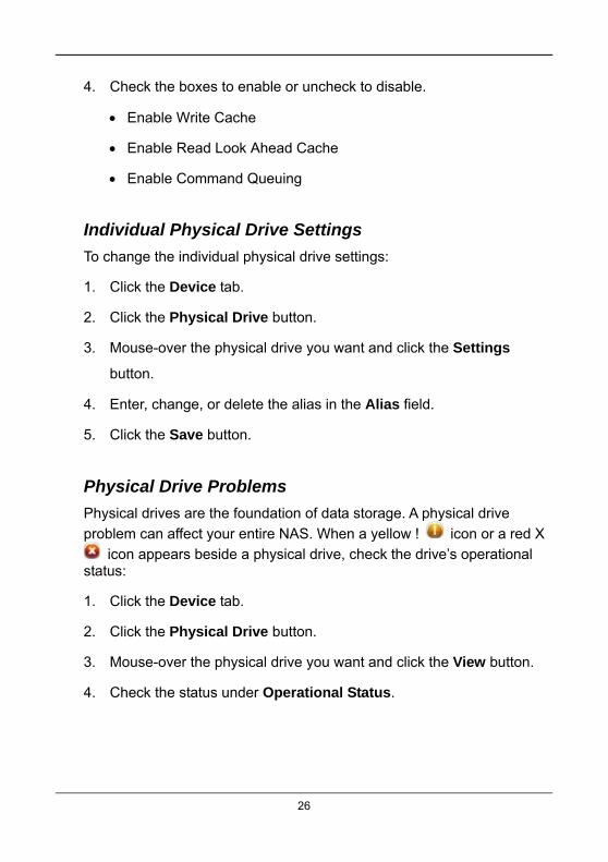
Individual Physical Drive Settings
To change the individual physical drive settings:
1. Click the Device tab.
2. Click the Physical Drive button.
3. Mouse-over the physical drive you want and click the Settings
button.
4. Enter, change, or delete the alias in the Alias field.
5. Click the Save button.
Physical Drive Problems
Physical drives are the foundation of data storage. A physical drive
problem can affect your entire NAS. When a yellow ! icon or a red X
icon appears beside a physical drive, check the drive’s operational status:
1. Click the Device tab.
2. Click the Physical Drive button.
3. Mouse-over the physical drive you want and click the View button.
4. Check the status under Operational Status.
26

27
3.6.5 iSCSI
View iSCSI Information
To view iSCSI information:
1. Click Device tab
2. Click the iSCSI button.
iSCSI information includes the following tabs.
Node
Portal
Port
Session
iSNS
CHAP
Ping
Setting up a CHAP
To set up a CHAP:
1. Click Device tab.
2. Click the iSCSI button.
3. Click the CHAP tab.
4. Complete the required settings.
User Name
Current Secret
password
Retype password
CHAP Type
Peer is one-way or uni-directional
Local is two-way or bi-directional
5. Click the Submit button.

28
3.6.6 Network
Basic Network Settings
1. Click Device tab.
2. Click the Network button.
Networking information includes:
ID
DHCP
IP Address
Gateway IP Address
Speed
MTU
Link
Changing Networking Configuration
1. Click Device tab.
2. Click Network button.
3. Mouse-over the network you and click the TCP/IP or IPV6 button.
4. Make the required settings.
Network Speed – Select the networking speed from the menu.
IP Properties
IP Address
Subnet Mask
Gateway IP Address
DNS Server IP Address
Secondary DNS Server IP Address
5. Click the Submit button.

29
Advanced Networking Configuration
1. Click Device tab.
2. Click Network button.
3. Click the Setup button.
4. Complete the required settings.
Computer Name
Enable Network Binding – Choose to enable or disable a biding.
Networking Binding – From the dropdown menu, choose a proper
biding type.
5. Click the Submit button.
Setting up a DHCP Server
1. Click Device tab
2. Click the Network button.
3. Click the DHCP Server button.
4. Make the required settings.
Enable DHCP Server – Choose to enable or disable the function.
IP range – Assign the IP range in the text boxes.
Lease Time
5. Click the Submit button.
Setting up DDNS
A Domain Name Service (DNS) translates human-readable host names, such as www.symantec.com, into IP addresses, such as 103.204.15.26, and back again.
A Dynamic DNS (DDNS) is required because in many cases, IP
30
addresses periodically change. The DDNS enables you to keep up-to-date and stay connected.
1. Click Device tab.
2. Click the Network button.
3. Click the DDNS button.
4. Make the required settings.
Enable DDNS – Check to enable uncheck to disable.
DDNS Server – Enter the IP address of the DDNS server.
User Name – Enter the user name to log in the DDNS server.
Password – Enter the password to log in the DDNS server.
5. Click the Submit button.
3.6.7 UPS
DNS-1250-04 and DNS-1250-06 support an Uninterruptible Power Supply (UPS).
View UPS Information
To display the information of the connected UPS:
1. Click Device tab.
2. Click the UPS button.
Setting up a UPS
To set up a UPS:
1. Click Device tab.
2. Click the UPS button.
3. Click the Setup button to bring up the Setup window.
4. Select the option you want and make the required settings.

31
5. Click the Submit button.
3.6.8 External USB Drive
External Drive Information
To display the information of the connected external USB drive:
1. Click the Device tab.
2. Click the External Drive button.
External drive information includes:
ID
Status
Model
Type
Location
Capacity
Cache
DNS-1250-04 and DNS-1250-06 support these external file systems:
EXT3
XFS
NTFS
HFS+
FAT32
Configuring an External Drive
To configure an external drive:
1. Click the Device tab.
2. Click the External Drive button.
3. Mouse-over the external drive and click the Settings button.
4. Choose the Write Policy (Write Through or Write Back).
5. Click the Save button.
Formatting an External Drive
To format an external drive:
1. Click the Device tab.

32
2. Click the External Drive button.
3. Mouse-over the external drive and click the Format button.
4. Choose the file format type (FAT32, NTFS, or XFS) and click the
Format button.

Caution
To safely remove an external USB drive, click the Remove button before you disconnect the drive.
Removing an External Drive
To remove an external drive:
1. Click the Device tab.
2. Click the External Drive button.
3. Mouse-over the external drive and click the Remove button.
4. Click the Confirm button.
3.7 Storage Tab The Storage tab enables you to create, manage, and delete disk arrays, logical drives, and spare drives.
The list of Disk Arrays provides disk array information, including:
ID – DA0, DA1, DA2, etc.
Alias – If assigned.
Status – Green, yellow or red icon.
Capacity – Data capacity of the disk array.
Free Capacity – Unconfigured or unused capacity on the physical
drives.
Media Patrol – Enabled or disabled on this disk array.
No. Of Logical Drives – The number of logical drives on this disk array.
3.7.1 Creating a Disk Array
You can also use the Wizard to create a disk array with logical drives and a spare drive at the same time.
33
34
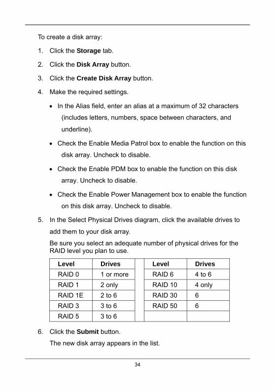
To create a disk array:
1. Click the Storage tab.
2. Click the Disk Array button.
3. Click the Create Disk Array button.
4. Make the required settings.
In the Alias field, enter an alias at a maximum of 32 characters
(includes letters, numbers, space between characters, and
underline).
Check the Enable Media Patrol box to enable the function on this
disk array. Uncheck to disable.
Check the Enable PDM box to enable the function on this disk
array. Uncheck to disable.
Check the Enable Power Management box to enable the function
on this disk array. Uncheck to disable.
5. In the Select Physical Drives diagram, click the available drives to
add them to your disk array.
Be sure you select an adequate number of physical drives for the RAID level you plan to use.
Level Drives Level Drives
RAID 0 1 or more RAID 6 4 to 6
RAID 1 2 only RAID 10 4 only
RAID 1E 2 to 6 RAID 30 6
RAID 3 3 to 6 RAID 50 6
RAID 5 3 to 6
6. Click the Submit button.
The new disk array appears in the list.

35
To create additional disk arrays, click the Create More button.
If you are done creating disk arrays, click the Finish button.
3.7.2 Creating a Logical Drive
After creating a disk array, you must create a logical drive on it.
To create a logical drive:
1. Click the Storage tab.
2. Click the Logical Drive button.
3. Click the Create Logical Drive button.
4. Click the disk array you want to use and click the Next button.
5. Make the required settings.
In the Alias field, enter an alias at a maximum of 32 characters
(includes letters, numbers, space between characters, and
underline).
Set the LDType.
NAS – Network Attached Storage
SAN/DAS – Storage Area Network / Direct Attached Storage
Choose a RAID Level from the dropdown menu.
The RAID levels available depend on the number of physical
drives in the disk array.
In the Capacity field, accept the default maximum capacity or
enter a lesser capacity (size in MB, GB or TB).
Any remaining capacity is available for an additional logical drive.
Choose the Stripe size

64 KB, 128 KB, 256 KB, 512 KB, or 1 MB.
Choose the Sector size
512 B, 1 KB, 2 KB, or 4 KB.
Choose the Read Policy
Read Cache, Read Ahead, or No Cache
Choose the Write Policy
Write Back or Write Through.
6. Click the Add button.
If there is capacity remaining, you can create an additional logical drive.
7. Click the Submit button.
The new logical drives appear in the Logical Drive list.
New logical drives are automatically synchronized. You can access the logical drive during synchronization.
Initializing a Disk Array
Initialization is normally done to logical drives immediately after they are created. Initialization sets all data bits in the logical drive to zero. The action removes any residual data left behind from earlier configurations. Initialization is recommended whenever you create a logical drive.
Caution
When you initialize a logical drive, all the data on the logical drive is lost. Backup any important data before you initialize a logical drive.
3.7.3 Disk Array Problems
Disk array problems typically result from a physical drive failure. The most common problem is a degraded disk array. The RAID controller can rebuild a degraded disk array.
A more serious, but far less common problem is an Incomplete Array. An incomplete array results from a physical drive that fails or becomes missing during:
36

37
RAID level migration
Disk array transport
Disk Array Degraded
Disk arrays are made up of physical drives. Logical drives are created on the disk array. When one of the physical drives in a disk array fails, a RAID 1, 5 and 10 volume will (or in the case of a RAID 6, two drives must fail):
The operational status of the disk array becomes Degraded.
The operational status of logical drives becomes Critical.
The operational status of physical drive becomes Dead or Offline.
Disk Array Offline
When a disk array and its logical drives go Offline, the data stored in the logical drives is no longer accessible.
Logical drives based on fault-tolerant disk arrays, RAID 1, 5, and 10, go
Offline when two physical drives are removed or fail.
RAID 6 can continue to operate when two physical drives are removed
or fail. It will fail when three physical drives are removed or fail.
Logical drives based on non-fault tolerant disk arrays, RAID 0, go
Offline when a one physical drive is removed or fails.
3.7.4 Disk Array Management
To view disk array information:
1. Click the Storage tab.
2. Click the Disk Array button.
3. Mouse-over the disk array you want to see and click the View button.
Disk array information includes:
Disk Array ID – DA0, DA1, DA2, etc.

38
Alias – If assigned
Operational Status – OK is normal
Media Patrol – Enabled or disabled on this array
PDM – Enabled or disabled on this array
Power Management
Total Capacity – Data capacity of the array
Configurable Capacity – Maximum usable capacity of the array
Free Capacity – Unconfigured or unused capacity on the physical
drives
Max Contiguous Free Capacity – Unconfigured or unused
capacity in contiguous sectors on the physical drives
Number of Physical Drives – The number of physical drives in this
array
Number of Logical Drives – The number of logical drives on this
array
To make disk array settings:
1. Click the Storage tab.
2. Click the Disk Array button.
3. Mouse-over the disk array you want to see and click the Settings
button.
4. Make settings as needed.
Change or delete the alias in the Alias field.
Enable or disable Media Patrol.

Enable or disable PDM.
Enable or disable Power Management.
5. Click the Save button.
Locating a Disk Array
To locate a disk array:
1. Click the Storage tab.
2. Click the Disk Array button.
3. Mouse-over the disk array you want and click the Locate button.
The drive carrier LEDs blink for one minute.
Deleting a Disk Array
To delete a disk array:
Disk Status LED Disk Activity LED
1. Click Storage tab.
2. Click the Disk Array button.
3. Mouse-over the disk array you want and click the Delete button.
4. Click the Confirm button.
Caution
When you delete a disk array, you also delete logical drives that belong to it, along with the data in the logical drives.
39

40
3.7.5 Logical Drive Management
Logical Drive Information
To view logical drive information:
1. Click the Storage tab.
2. Click the Logical Drive button.
3. Mouse-over the logical drive and click the View button. information
includes:
Disk Array ID – LD0, LD1, LD2, etc.
Alias – If assigned
Array ID – ID number of the disk array where this logical drive was
created
RAID Level – Set when the logical drive was created
Operational Status – OK means normal
Capacity – Data capacity of the logical drive
Number of Axles – For RAID 10 and 50, 2 axles
Physical Capacity – Data capacity of the physical drives
Number of Physical Drives – The number of physical drives
Stripe size – Set at logical drive creation
Read Policy – Adjustable
Sector size – Set at logical drive creation
Write Policy – Adjustable
Tolerable Number of Dead Drives – Number of physical drives that
can fail without the logical drive going offline

41
Synchronized – A new logical drive shows “No” until synchronizing
is completed
Parity Pace – Pertains to some RAID levels
WWN – World Wide Number, a unique identifier assigned to this
logical drive
Codec Scheme – Pertains to some RAID levels
Serial Number – Assigned to this logical drive
ALUA Access State For Ctrl1
ALUA Access State For Ctrl2
LDType – Displays the LD type of the logical drive.
Logical Drive Settings
To make logical drive settings:
1. Click the Storage tab.
2. Click the Logical Drive button.
3. Mouse-over the logical drive you want and click the Settings button.
4. Make setting changes are required.
Change or delete the alias in the Alias field.
Read Policy – ReadCache, ReadAhead, or NoCache
Write Policy – WriteThru or WriteBack
5. Click the Save button.
Logical Drive Check Tables
To view logical drive check tables:
1. Click the Storage tab.

42
2. Click the Logical Drive button.
3. Mouse-over the logical drive you want and click the Check Table
button.
4. Choose an option.
All – All errors. The default choice.
Read Check – Read errors for this logical drive.
Write Check – Write errors for this logical drive.
Inconsistent Block – Inconsistent blocks for this logical drive.
Mirror data for RAID Levels 1, 1E and 10.
Parity data for RAID Levels 5, 6, and 50.
Errors and inconsistent blocks are identified by Redundancy
Check.
Each Check Table lists:
Entry Number – A number assigned to each block of entry.
Table Type – Read Check, Write Check or Inconsistent Block.
Starting Logical Block Address – LBA of the first block for this
entry.
Count – Number of errors or continuous blocks starting from this
LBA.
Locating a Logical Drive
To locate a logical drive:
1. Click the Storage tab.
2. Click the Logical Drive button.

43
3. Mouse-over the disk array you want and click the Locate button.
The drive carrier LEDs blink for one minute.

44
Disk Status LED Disk Activity LED
Deleting a Logical Drive
To delete a logical drive:
1. Click the Storage tab.
2. Click the Logical Drive button.
3. Mouse-over the disk array you want and click the Delete button.
4. Click the Confirm button.
Caution
When you delete a logical drive, you also delete all the data in the logical drive. Backup important data before you delete a logical drive.
Redundancy Check
To run Redundancy Check on a logical drive:
1. Click the AdminTool tab
2. Click the Background Activity button.
The list of background activities appears.
3. Mouse-over Redundancy Check and click the Start button.
4. Check the boxes to the left of the logical drives you want to run.
5. Check the options you want.
Auto Fix – Attempts to repair the problem when it finds an error
Pause on Error – The process stops when it finds a non-repairable
error
45
6. Click the Confirm button.
Synchronization Settings
To change Synchronization settings:
1. Click the AdminTool tab.
2. Click the Background Activity button.
3. Click the Settings button.
4. Click the Background Synchronization Rate dropdown menu and
choose a rate.
Low – Fewer system resources to Synchronization, more to data
read/write operations.
Medium – Balances system resources between Synchronization
and data read/write operations.
High – More system resources to Synchronization, fewer to data
read/write operations.
5. Click the Confirm button.
3.7.6 Logical Drive Problems
Logical drive problems typically result from a physical drive failure. The most common problem is a critical logical drive. The RAID controller can rebuild a critical logical drive.
A more serious but far less common problem is an Incomplete Array. An incomplete disk array results from a physical drive that fails or becomes missing during:
RAID level migration
Physical drive transport
46
3.7.7 Spare Drive Management
If you have an unassigned physical drive, you can assign it as a spare drive. A spare drive is a physical drive designated to replace a failed physical drive in a RAID Volume.
Spare drive support depends on which NAS model you have.
DNS-1250-04 supports up to four physical drives.
In the event of the failure of a physical drive within a RAID 1 or three-drive RAID 1E, or RAID 5 Volume, the spare drive is activated to replace the failed physical drive.
A spare drive is not available for a RAID 10 Volume because RAID 10 requires all four physical drives.
DNS-1250-06 supports up to six physical drives.
In the event of the failure of a physical drive within any Volume except RAID 0 and RAID 6, the spare drive is activated to replace the failed physical drive.
A spare drive is not available for a RAID 6 Volume because RAID 6 requires all six physical drives.
Spare Drive Information
To view spare drive information:
1. Click the Storage tab.
2. Click the Spare Drive button.
3. Mouse-over the spare drive you want to see and click the View
button.
Spare drive information includes:
ID – Spare drive ID
Status – Green, yellow or red icon.
Capacity – Data capacity of the spare drive.
Physical Drive ID

47
Revertible – Yes or No
Type – Global or Dedicated
Dedicated to Array – ID of the disk array
Assigning a Spare Drive
To assign a spare drive:
1. Click the Storage tab.
2. Click the Spare Drive button.
3. Mouse-over the spare drive you want and click the Settings button.
4. Make settings changes as needed.
Revertible – Enables you to run a transition to return the drive to
spare status.
Type
Global – Supports all disk arrays
Dedicated – Supports only the designated disk array
Dedicated to Array – ID of the designated disk array
5. Click the Confirm button.
3.8 AdminTool Tab The AdminTool tab enables you to:
Manage the NAS subsystem or virtual enclosure
Monitor events
Manage background activities
Perform firmware updates
Restore factory default settings

48
Save a NAS configuration report
3.8.1 NAS Subsystem Management
Viewing NAS System Information
To view NAS system information:
1. Click the AdminTool tab.
2. Click the Subsystem Information button.
NAS system information includes:
Alias, if assigned
Vendor
Model
WWN – World Wide Name
Serial Number
Part Number
Revision Number
System Date & Time
Making NAS System Settings
To make NAS system settings:
1. Click the AdminTool tab.
2. Click the Subsystem Information button.
3. Click the Settings button.
4. In the Alias field, enter an alias or change the existing alias.
5. Click the Save button.
49
3.8.2 NAS System Shutdown and Restart
To restart or shut down the subsystem:
1. Click the AdminTool tab.
2. Click the Subsystem Information button.
3. Click the Shutdown/Restart button.
4. Do one of the following actions.
Click the Shutdown button to shut down the subsystem.
Click the Restart button restart the subsystem.
I/O operations are stopped during this operation.
Click the Power Off button to turn off power to the subsystem.
After power off, unplug the power cord from the subsystem then plug it in to reactivate the power supply unit.
3.8.3 Clearing Subsystem Statistics
To clear statistics on the physical drives, logical drives, and controller:
1. Click the AdminTool tab.
2. Click the Subsystem Information button.
3. Click the Clear Statistics button.
4. Click the Confirm button.
3.8.4 Software Service Management
Starting a Software Service
To start a software service:
1. Click the AdminTool tab.
2. Click the Service button.

50
3. Mouse-over the service you want and click the Start button.
4. Click the Confirm button.
Making Software Service Settings
To make software service settings:
1. Click the AdminTool tab.
2. Click the Service button.
3. Mouse-over the service you want and click the Settings button.
4. Make the setting changes as needed.
5. Click the Save button.
3.8.5 Runtime and NVRAM Event Logs
Runtime events are the 1023 most recent events since the last NAS startup.
Viewing Runtime Events
To view runtime events:
1. Click the AdminTool tab.
2. Click the Events button.
Runtime Event information includes:
Index – A number assigned to this specific event. The highest
number is most recent
Device – Identifies the device involved
Event ID – Identifies the action that occurred
Severity
Fatal – Non-Recoverable error or failure has occurred

51
Critical – Action is needed now and the implications of the
condition are serious
Major – Action is needed now
Minor – Action is needed but the condition is not a serious at this
time
Warning – User can decide whether or not action is required
Info – Information only, no action is required
Time – Date and time the event occurred.
Description – Plain language description of the event.
Viewing NVRAM Events
NVRAM events are the most important events since the last subsystem start-up.
To view NVRAM events:
1. Click the AdminTool tab.
2. Click the Events button.
3. Click the NVRAM Events button.
NVRAM Events information is the same as Runtime events, above.
Clearing Events
To clear an event log:
1. Click the AdminTool tab.
2. Click the Events button.
3. Click the NVRAM Events button or the Runtime Events button.
4. Click the Clear button.
5. Click the Confirm button.

52
Saving Events
To save an event log:
1. Click the AdminTool tab.
2. Click the Events button.
3. Click the NVRAM Events button or the Runtime Events button.
4. Click the Save button.
Your browser saves a text file containing the event log to its designated download folder.
3.8.6 Background Activity
Each background activity has its own set of parameters. The most important parameters are: Status and Progress. The Status displays:
Running – Now in progress.
Paused – Waiting for a higher priority activity to finish or waiting for you
to click the Resume button.
Media Patrol
Media Patrol is a routine maintenance procedure that checks the magnetic media on each physical drive. Media Patrol checks all physical drives assigned to disk arrays and spare drives. Media Patrol does not check un-configured drives.
Media Patrol checks are enabled by default on all disk arrays and spare drives. You can disable Media Patrol in the disk array and spare drive settings, however that action is not recommended.
Unlike Synchronization and Redundancy Check, Media Patrol is concerned with the condition of the media itself, not the data recorded on the media. If Media Patrol encounters a critical error, it triggers PDM if PDM is enabled on the disk array.
Media Patrol has three status conditions:
Running – Normal. You can access your logical drives at any time.

Yield – Temporary pause while a read/write operation takes place.
Paused– Temporary pause while another background activity runs. Or a
pause initiated by the user.
Redundancy Check
Redundancy Check is a routine maintenance procedure for fault-tolerant disk arrays (those with redundancy) that ensures all the data matches exactly. Redundancy Check can also correct inconsistencies.
Rebuild
When you rebuild a disk array, you are actually rebuilding the data on one physical drive.
When a physical drive in a disk array fails and a spare drive of adequate capacity is available, the disk array begins to rebuild automatically using the spare drive.
If there is no spare drive of adequate capacity, but the Auto Rebuild function is ENABLED, the disk array begins to rebuild automatically as soon as you remove the failed physical drive and install an un-configured physical drive in the same slot.
If there is no spare drive of adequate capacity and the Auto Rebuild function is DISABLED, you must replace the failed drive with an un-configured physical drive, perform a Manual Rebuild. See below.
Important
If your replacement physical drive was formerly part of a different disk array or logical drive, you must clear the configuration data on the replacement drive before you use it.
Migration
The term Migration means either or both of the following actions:
Change the RAID level of a logical drive.
Expand the storage capacity of a logical drive.
Before you begin a migration, examine your current disk array to
53

54
determine whether:
The physical drives in your array can support the target RAID level.
There is sufficient capacity to accommodate the target logical drive size.
If you need to add physical drives to your array, be sure there are unassigned physical drives are installed in your RAID system before you begin migration.
Supported RAID levels
Target
Source RAID 0 RAID 1 RAID 1E RAID 5 RAID 6 RAID 10 RAID 50
RAID 0 ● ● ● ● ● ● ●
RAID 1 ● ● ● ● ●
RAID 1E ● ● ● ● ●
RAID 5 ● ● ● ● ● ●
RAID6 ●
RAID 10 ● ● ● ● ● ●
RAID 50 ● ● ● ● ● ●
PDM
Predictive Data Migration (PDM) is the migration of data from the suspect physical drive to a spare physical drive, similar to rebuilding a logical drive. But unlike Rebuilding, PDM constantly monitors your physical drives and automatically copies your data to a spare physical drive BEFORE the physical drive fails and your logical drive goes Critical.
The following actions trigger PDM:
A physical drive with unhealthy status (see below).
Media Patrol finds a disk critical error.
You initiate PDM manually.
PDM also counts the number of media errors reported by Media Patrol.
A physical drive becomes unhealthy when:

55
A SMART error is reported.
The bad sector remapping table fills to the specified level.
You can specify the maximum levels for the reassigned and error blocks in PDM settings. When the table fills to a specified value, PDM triggers a migration of data from the suspect drive (the physical drive with the bad sectors) to a replacement drive.
During data migration, you have access to your logical drives but they respond more slowly to read/write tasks because of the additional operation. The time required for data migration depends on the size of the physical drives.
PDM is enabled on all disk arrays by default. You can disable PDM in the disk array settings, however that action is not recommended.
Transition
Transition is the process of replacing a revertible spare drive that is currently part of a disk array with an un-configured physical drive or a non-revertible spare. The revertible spare drive returns to its original status. In order to run the Transition function, the spare drive must be revertible.
In addition, you must specify an un-configured physical drive of the same or larger capacity and same media type as the revertible spare drive.
Synchronization
Synchronization is automatically applied to logical drives when they are created. Synchronization recalculates the redundancy data to ensure that the working data on the physical drives is properly in sync.
Mouse-over on the logical drive, click the View button, and look under Logical Drive Information beside the line that says Synchronized. A Yes means the logical drive was synchronized.
Running a Background Activity
To run a background activity:
1. Click the AdminTool tab.
2. Click the Background Activity button.
3. Click the Start button beside the activity you want to run.

56
Scheduling a Background Activity
To add a scheduled background activity:
1. Click the AdminTool tab.
2. Click the Background Activity button.
3. Click the Scheduler button.
4. Click the Add Schedule button.
5. Make the required settings.
Scheduler (Activity) Name – Select Media Patrol, Battery
Recondition, Power On, Redundancy Check, Spare Check, or
Power Off.
If you select Redundancy Check, the following settings need to be
completed:
Auto Fix – Attempts to repair the problem when it finds an error.
Pause on Error – The process stops when it finds a non-repairable
error.
Select LD – Select at least one logical drive on which Redundancy
Check will run.
Enable This Schedule – Select to enable this function.
Start Time – Choose a start time.
Recurrence Pattern – Select a Recurrence Pattern as Daily,
Weekly, or Monthly.
Start From – Select a start date.
End On – Select an end option.
6. Click the Save button.

57
Viewing a List of Scheduled Background Activities
To view a list of scheduled background activities:
1. Click the AdminTool tab.
2. Click the Background Activity button.
3. Click the Scheduler button.
The list of Scheduled Background Activities displays.
Type – Media Patrol, Redundancy Check, or Spare Check.
Recurrence – Daily, weekly, monthly.
Start Time – Date and time.
Operational Status – Enabled or disabled.
Changing a Scheduled Background Activity
To change a scheduled background activity:
1. Click the AdminTool tab.
2. Click the Background Activity button.
3. Click the Settings button.
4. Make settings changes are required.
Rate – Choose a Rate from the dropdown menu for each activity.
Low – Fewer system resources to the Rebuild, more to data
read/write operations.
Medium – Balances system resources between the Rebuild and
data read/write operations.
High – More system resources to the Rebuild, fewer to data
read/write operations.
Reassigned Block Threshold – Enter a value in the blocks field.

Error Block Threshold – Enter a value in the blocks field.
Enable Media Patrol – Check the box to enable.
Enable Auto Rebuild – Check the box to enable.
5. Click the Confirm button.
3.8.8 Firmware Updates
Before you update the firmware, go to the D-Link website http://www.dlink.com/ and download the latest firmware image file to your PC or Mac.
1. Click the AdminTool tab.
2. Click the Firmware Update button.
The NAS Firmware Update window screen appears showing the current Image Version Number.
3. Click the Browse button to locate the firmware image file, and then
click the Open button.
The firmware image file appears in the in the field.
4. Click the Submit button.
Warning
Do NOT power off the system during the update!
When the update is completed a message tells you to reboot the subsystem.
5. Click the OK button to restart the system.
58

59
3.8.9 Performance Monitor
The Performance Monitor screen allows you to monitor the performance of NAS using the analyzed illustrations.
Monitored Components
Logical Drive
Physical Drive
Port
Bandwidth ● ● ●
Cache Usage ●
Dirty Cache ●
Maximum Latency ● ● ●
Average Latency ● ● ●
Minimum Latency ● ● ●
IO request ● ● ●
Viewing Logical Drive Performance
To view the Logical Drive performance:
1. Click the AdminTool tab.
2. Click the Performance Monitor button.
3. Click the Select Logical Drives button to choose the logical drive
you want.
4. Choose a performance type from the dropdown menu.
Viewing Physical Drive Performance
To view the Physical Drive performance:
1. Click the AdminTool tab.
2. Click the Performance Monitor button.
3. Click the Select Physical Drives button to choose the physical drive
you want.

4. Choose a performance type from the dropdown menu.
Viewing Port Performance
To view the Port performance:
1. Click the AdminTool tab.
2. Click the Performance Monitor button.
3. Click the Select Ports button to choose the port you want.
4. Choose a performance type from the dropdown menu.
3.8.10 Restore Factory Default Settings
The Restore Factory Default function restores the default settings for the NAS system.
Caution
Use this feature only when required and only on the settings that you must reset to default in order to set them correctly.
To restore the factory default settings:
1. Click the AdminTool tab.
2. Click the Restore Factory Default button.
3. Check the boxes beside the settings you want to reset to default
value.
4. Click the Submit button.
5. Click the OK button in the confirmation box.
60

61
3.8.11 System Configuration Files
Importing a System Configuration File
To import the configuration file to the NAS:
1. Click the AdminTool tab.
2. Click the Configuration File button.
3. Click the Import button.
4. Click the Browse button to locate the configuration file (.bcf), and
click the Open button.
5. Click the Submit button.
The NAS system automatically reboots.
Exporting a System Configuration File
To export the current configuration file:
1. Click the AdminTool tab.
2. Click the Configuration File button.
3. Click the Export button.
4. Click the Submit button.
The current configuration is saved as a .bcf file in your Host PC.
3.8.12 LUNMap Management
The LUN Mapping function allows you to control what storage arrays are visible to which computers.
Adding an Initiator
To add an initiator:
1. Click the AdminTool tab.
2. Click the LUNMap button.

62
3. Click the Add Initiator button.
4. Enter a name in the Initiator Name field and click the Submit button.
The initiator is added in the LUNMap list.
Defining LUN Mapping
To define the LUN Mapping:
1. Click the AdminTool tab.
2. Click the LUNMap button.
3. Click the LUN Mapping button.
4. Select the initiator you want from the dropdown menu and click the
Next button.
5. In the LUN Mapping field, indicate the arrays you wish to make
visible by putting a unique number in the LUN field.
6. Click the Assign button.
7. Click the Submit button.
8. Check the Enable LUN Masking option to enable the LUN Mapping
and Masking function of the NAS.
3.8.13 Power Option
The Power Option screen displays the power management of the NAS system.
To change Power Option settings:
1. Click the AdminTool tab.
2. Click the Power Option button.
3. Mouse-over the item and clicking the Settings button.

63
Power On LAN – When the NAS system is shut down, this feature
powers on automatically in the event of network activity.
Power On Automatically – When to power on the NAS system
automatically.
4. Click the Save button.
3.8.14 Message Alerts
The Message Alert function allows the user to receive an e-mail alert for the events of the NAS system.
Setting-up Email Alert Service
To set up the e-mail service for the NAS system:
1. Click the AdminTool tab.
2. Click the Message Alert button.
3. Click the Setup button.
4. Make the settings as required.
Enable Services – Check to enable message alert service.
SMTP Server – Enter the IP address of SMTP server.
SMTP Port – Enter the port number of SMTP server
From – The sender of the notification message.
SMTP Authentication
Username – Enter the username to log in the SMTP server.
Password – Enter the password to log in the SMTP server.
5. Click the Save button.

64
Adding an E-Mail Account
To add an E-Mail account:
1. Click the AdminTool tab.
2. Click the Message Alert button.
3. Click the Create button.
4. Enter your e-mail address.
5. Click the Save button.
Editing an E-Mail Account
To edit an E-Mail account:
1. Click the AdminTool tab.
2. Click the Message Alert button.
3. Mouse-over the e-mail account you want to edit and click the Setting
button.
4. Change the email address as required.
5. Click the Save button.
Deleting an E-Mail Account
To delete an E-Mail account:
1. Click the AdminTool tab.
2. Click the Message Alert button.
3. Mouse-over the e-mail account you want to edit and click the Delete
button.
4. Click the Confirm button.

65
3.8.15 Network Security
Setting-up a Security Policy
To set up a Security Policy:
1. Click the AdminTool tab.
2. Click the Network Security button.
3. Click the Security Policy button.
4. Make the required settings.
HTTPs Redirection
I/O Policy
IP Address or Domain Name
5. Click the Save button.
Setting-up Access Protection
To set up Access Protection:
1. Click the AdminTool tab.
2. Click the Network Security button.
3. Click the Access Protection button.
4. Make the required settings.
Enable Services – Check to enable.
Block Policy – Time interval and number of unsuccessful attempts.
Protocols – Choose one or more. SSH, Telnet, FTP, AFP, Samba,
WebDAV, and HTTP/HTTPs.
5. Click the Save button.

66
Setting-up an SSL Certificate
To set up SSL Certificate:
1. Click the AdminTool tab.
2. Click the Network Security button.
3. Click the SSL Certificate button.
4. Make the required settings.
Specific SSL Certificate – Check to enable the function.
Certificate (X.509 format)
Private Key (X.509 format)
5. Click the Save button.
3.9 NAS Tab
3.9.1 Setup Wizard
The system’s Wizard lets you configure your disk array(s) easily and quickly. The Wizard will guide you through the required settings step by step. You can choose to configure:
Automatically using One-Click Setup.
Manually using Advance Setup
Using the Automatic Configuration Wizard
1. Click the NAS tab.
2. Click the Wizard button.
3. Click the One-Click Setup tab.
The Summary window displays the general information of the system, including:
Computer Name – Of the NAS system

67
IP Address – Of the NAS system
Storage Type – Data Protection
4. To accept the proposed configuration, click the Submit button.
The NAS system creates the RAID volume based on the number of the physical drives available.
1 drive – RAID 0 2 drives – RAID 1
3 to 5 drives – RAID 5 6 drives – RAID 6
If you disagree with the proposed configuration, click the Advance Setup button to directly specify your parameters.
Using the Advanced Configuration Wizard
1. Click the NAS tab.
2. Click the Wizard button.
3. Click the Advance Setup tab.
4. Make settings as required.
Computer Name – Of the NAS system.
Obtain an IP address automatically – Requires a DHCP server on
your network.
IP Address – Of the NAS system.
Subnet Mask – Of your network.
Default Gateway Mask – Of your network.
Primary DNS Mask – Of your network.
Secondary DNS Mask – Of your network.
5. Click the Next button.
6. Choose a Storage Type.
Data Protection – RAID 0

68
Maximum Capacity – The RAID level depends on number of
physical drives available.
7. Click the Next button.
The Summary window displays the general information of the system, including:
Computer Name – Of the NAS system
IP Address – Of the NAS system
Storage Type – Data Protection or Maximum Capacity
8. To accept the proposed configuration, click the Submit button.
3.9.2 User Account Management
Adding Users
To add users for the NAS system:
1. Click the NAS tab.
2. Click the NAS User button.
3. Click the Create User button.
4. Make settings as required.
User Name
Password
Retype Password
5. Click the Save button.
See “Making User and Group Permission Settings” on page 70.
Editing User Information
To edit user information:
1. Click the NAS tab.

2. Click the NAS User button.
3. Mouse-over the user you want and click the Change Password
button.
4. Type the new password in the fields provided.
5. Click the Save button.
Deleting Users
To delete a user:
1. Click the NAS tab.
2. Click the NAS User button.
3. Mouse-over the user you want to delete and click the Delete button.
4. Click the Confirm button.
Adding a Group of Users
To add a group of users:
1. Click the NAS tab.
2. Click the NAS User button.
3. Click the Group button.
4. Click the Create Group button.
5. Enter the Group Name and click the Next button.
6. Click the users under NAS users to move them to under the Group
name and click the Submit button.
Note
You cannot add the administrator or guest users to a group. Each user can only belong to one group.
69
70
Adding and Removing Users from a Group
To add or remove users from a group:
1. Click the NAS tab.
2. Click the NAS User button.
3. Click the Group button.
4. Mouse-over the group you want to change and click the Group
Settings button.
5. Click each user name to move it to the other list.
Group Name – Members of this group
NAS User – Not a member of this group
6. Click the Save button.
Making User and Group Permission Settings
When the new user or group is added, you must make permission settings for each user/group to access the system. Follow the steps below to complete the settings:
1. Click the NAS tab.
2. Click the File Sharing button.
3. From the File Sharing list, mouse-over the folder you want and click
the Share Settings button.
4. Select the user or group you want and set one of the access options.
Deny-Access, Read-Only, or Read-Write
5. Click the Save button.
Deleting a Group of Users
To delete a group:

1. Click the NAS tab.
2. Click the NAS User button.
3. Click the Group button.
4. Mouse-over the group you want to delete and click the Delete button.
5. Click the Confirm button.
Note
You must delete all users from a group before you can delete the group.
3.9.3 Protocol Control and Setting
1. Click the NAS tab.
2. Click the Protocol Control button.
3. In the Protocol Control list, mouse-over the protocol option you want
and click the Enable/Disable button to turn the feature on or off.
To configure the advanced settings, mouse-over the protocol option and click the Settings button.
3.9.4 File System Management
Viewing File System Information
To view file system information:
1. Click the NAS tab.
2. Click the File System button.
3. In the File System list, mouse-over the item you want and click the
View button.
71

72
Setting a File System Quota
To set a file system quota:
1. Click the NAS tab.
2. Click the File System button.
3. In the File System list, mouse-over the item you want and click the
Quota button.
Deleting a File System
To delete a file system:
1. Click the NAS tab.
2. Click the File System button.
3. In the File System list, mouse-over the item you want and click the
Delete button.
4. Click the Confirm button.
3.9.5 File Sharing Management
Creating an ISO Folder
1. Click the NAS tab.
2. Click the File Sharing button.
3. Click the Create ISO Folder button.
4. Enter the Source Folder, ISO Image File and Folder Name, and click
the Next button.
5. Select the protocol and click the Next button.
6. Windows/FTP or UNIX/LINUX only. In the Permission Setting field,
set the privilege for the users to access the folder.

73
Deny-Access, Read-Only, or Read-Write
Click the Next button.
7. Click the Submit button.
Making ISO Folder Settings
1. Click the NAS tab.
2. Click the File Sharing button.
3. In the File Sharing list, mouse-over the folder you want and click the
Share Setting button.
4. Make settings changes as required.
Windows/Mac/FTP/WebDAV – Select the Protocol for your
networking configuration. Set the Permissions for each user and
group.
UNIX/LINUX – Add the IP address in the New IP Address box then
click the Add button for sharing.
Enter *.*.*.* if all IP addresses are allowed to share.
5. Click the Save button.
Creating a Folder
1. Click the NAS tab.
2. Click the File Sharing button.
3. Click the Create Folder button.
4. Enter the Volume and Folder Name and click the Next button.
5. Select the protocol as Windows/FTP or UNIX/LINUX and click the
Next button.

74
6. In the Permission Setting field, set the privilege for the users to
access the folder and click the Next button.
Deny-Access, Read-Only, or Read-Write
7. Click the Submit button.
Changing Folder Settings
1. Click the NAS tab.
2. Click the File Sharing button.
3. In the File Sharing list, mouse-over the folder and click the Share
Setting button.
4. Make settings changes as required.
Windows/Mac/FTP/WebDAV – Select the Protocol for your
networking configuration, and set up the Permission Setting for
each user/group.
UNIX/LINUX – Add the IP address in the New IP Address box then
click the Add button for sharing.
Enter *.*.*.* if all IP addresses are allowed to share.
5. Click the Save button.
Setting up Folder Sharing
1. Click the NAS tab.
2. Click the File Sharing button.
3. In the File Sharing list, mouse-over the folder and click the Share
Setting button.
4. Make settings as required.
Windows (CIFS)
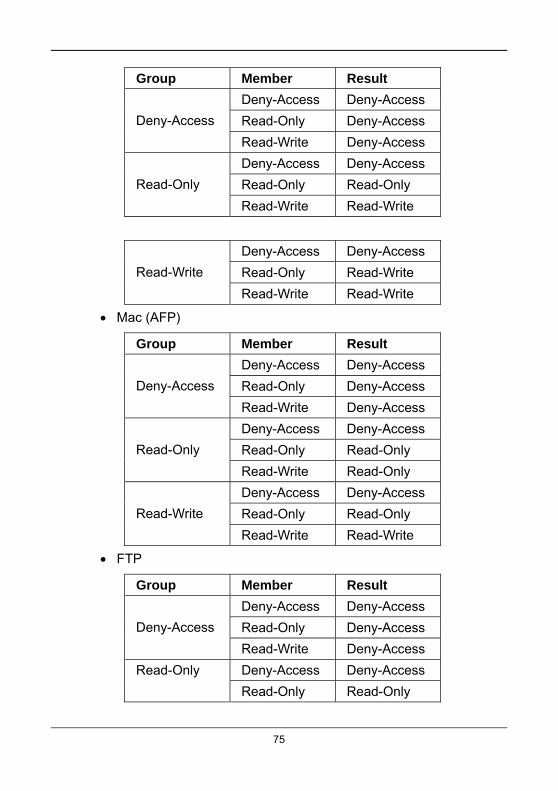
75
Group Member Result
Deny-Access Deny-Access
Read-Only Deny-Access Deny-Access
Read-Write Deny-Access
Deny-Access Deny-Access
Read-Only Read-Only Read-Only
Read-Write Read-Write
Deny-Access Deny-Access
Read-Only Read-Write Read-Write
Read-Write Read-Write
Mac (AFP)
Group Member Result
Deny-Access Deny-Access
Read-Only Deny-Access Deny-Access
Read-Write Deny-Access
Deny-Access Deny-Access
Read-Only Read-Only Read-Only
Read-Write Read-Only
Deny-Access Deny-Access
Read-Only Read-Only Read-Write
Read-Write Read-Write
FTP
Group Member Result
Deny-Access Deny-Access
Read-Only Deny-Access Deny-Access
Read-Write Deny-Access
Deny-Access Deny-Access Read-Only
Read-Only Read-Only

76
Read-Write Read-Write
Deny-Access Deny-Access
Read-Only Read-Write Read-Write
Read-Write Read-Write

77
WebDAV
Group Member Result
Deny-Access Deny-Access
Read-Only Deny-Access Deny-Access
Read-Write Deny-Access
Deny-Access Deny-Access
Read-Only Read-Only Read-Only
Read-Write Read-Only
Deny-Access Deny-Access
Read-Only Read-Only Read-Write
Read-Write Read-Write
UNIX/LINUX -- Add the IP address in the New IP Address box
then click the Add button for sharing.
Enter *.*.*.* if all IP addresses are allowed to share.
5. Click the Save button.
3.9.6 Backup Management
Choosing a Backup Solution
1. Click the NAS tab.
2. Click the Backup button.
3. Click the tab for the Backup solution you want.
Snapshot Backup
Remote Backup
Local Backup
Client Backup

78
Amazon S3
Setting up Snapshot Backup
1. Click the NAS tab.
2. Click the Backup button.
3. Click the Snapshot Backup tab.
4. Click the Create button.
5. Make settings as required.
Choose a Volume from the dropdown menu.
From the Reserve Capacity for Snapshot dropdown menu, assign
the reserved capacity for the backup solution.
Check the Auto Extend box to enable this function.
Choose a Snapshot schedule.
Disable – No snapshots taken.
Time interval by hour – Snapshots are taken at the hourly interval
you choose from the dropdown menu.
Daily – Snapshots are taken at the time of day you choose from
the dropdown menus.
Weekly – Snapshots are taken on the day of the week, at the time
of day you choose from the dropdown menus.
6. Click the Run button.
The new backup schedule is applied.
Changing Snapshot Backup Schedule Settings
1. Click the NAS tab.
79
2. Click the Backup button.
3. Click the Snapshot Backup tab.
4. Mouse-over the item schedule you want and click the Settings
button.
5. Make settings as required.
6. Click the Run button.
The new backup schedule is applied.
Deleting a Snapshot Backup Schedule
1. Click the NAS tab.
2. Click the Backup button.
3. Click the Snapshot Backup tab.
4. Mouse-over the item schedule you want and click the Delete button.
5. Click the Confirm button.
Performing a Remote Backup
1. Click the NAS tab.
2. Click the Backup button.
3. Click the Remote Backup tab.
4. Click the Create button.
5. Make settings as required.
Source Path
Backup Server – Enter the IP address of the remote backup
server.
Port -- Enter the port number for the remote backup server.

User Name – Enter the user name to login the remote backup
server.
Password – Enter the password to login the remote backup
server.
Enable SSL – Select this option if the server requires SSL.
Snapshot – Select this option if you want to upload snapshot of
backup to the server.
Choose a Snapshot schedule.
Disable – No snapshots are taken.
Time interval by hour – Snapshots are taken at the hourly interval
you choose from the dropdown menu.
Daily – Snapshots are taken at the time of day you choose from
the dropdown menus.
Weekly – Snapshots are taken on the day of the week, at the time
of day you choose from the dropdown menus.
6. Click the Test button to test the server before applying the settings.
7. Click the Run button.
Notes
The USB port on the front panel backs- up files from the
Flash drive to the NAS system.
The four USB ports on the back panel back-up files from
the NAS system to the Flash drive.
80

81
Local Backup
Local Backup enables you to change the backup services of the NAS system and the USB storage device.
To set the Local Backup settings:
1. Click the NAS tab.
2. Click the Backup button.
3. Click the Local Backup tab.
4. Mouse-over the USB device you want and click the Settings button.
5. Make settings as required.
Check the Enable Services box to enable the backup solution.
Choose a Backup Method from the dropdown menu.
Add, Directory, Copy, or Synchronize.
Choose the Folder Name you want from the list.
6. Do one of the following actions.
Click the Save button to apply the settings.
Click the Run button to backup immediately.
Select the schedule type you want for the backup solution.
Enabling One-Touch Backup
One-Touch Backup enables you to back-up specified folders from your PC to the NAS system by simply pressing a button on the front of the NAS system.
1. Click the NAS tab.
2. Click the Backup button.
3. Click the Client Backup tab.

4. Check the One Touch Backup box to enable this backup solution.
With One-Touch Backup enabled, press the One-Touch Backup button the front of the NAS system.
One-Touch Backup Button
To disable One-Touch Backup:
1. Click the NAS tab.
2. Click the Backup button.
3. Click the Client Backup tab.
4. Uncheck the One Touch Backup box.
5. Click the Save button.
Amazon S3 Backup
Amazon S3 enables you to upload backup files to an Amazon S3 server.
1. Click the NAS tab.
2. Click the Backup button.
3. Click the Amazon S3 tab.
4. Click the Create button.
5. Make the required settings in the Create Amazon S3 Backup window.
82

83
Local Path
Direction
Download – From the Amazon S3 to your system
Upload – From your system to the Amazon S3
Access Key – For the Amazon S3 server
Private Key – For the Amazon S3 server
Retries Number
Incremental Backup – Backs up updated files only.
Synchronized Backup – Deletes any extra files while
synchronizing.
Schedule
Disable – No snapshots are taken.
Time interval by hour – Snapshots are taken at the hourly interval
you choose from the dropdown menu.
Daily – Snapshots are taken at the time of day you choose from
the dropdown menus.
Weekly – Snapshots are taken on the day of the week, at the time
of day you choose from the dropdown menus.
6. Click the Run button.
The new backup schedule is applied.
Click the Test button to test the server before applying the settings.
To change the settings of the backup solution, move you mouse over the item you want and click the option button.
3.9.7 Plug-in Management
You must download the plug-in to your PC before you can add it to ShareCenter Pro.
To add a plug-in:
1. Click the NAS tab.
2. Click the Plug-in button.
3. Click the Add button.
4. Click the Browse button and navigate to the plug-in you want to add.
5. Click the Install button.
The plug-in is added.
Warning
Do not disconnect the power or shut down the NAS system while the plug-in installation is running!
To manage a plug-in:
1. Click the NAS tab.
2. Click the Plug-in button.
3. In the plug-in list mouse-over the plug-in you want and,
Click the Open button to display the plug-in application in a new
window.
Click the Stop button to stop the plug-in.
Click the Start button to start the plug-in.
Click the Re-Install button to re-install the plug-in.
84

85
3.9.8 iSCSI Initiator Management
The iSCSI feature enables you to use the disk volume on NAS system as a virtual drive on your computer.
To add an iSCSI initiator:
1. Click the NAS tab.
2. Click the iSCSI Initiator button.
3. Click the Create button.
4. Enter the required information.
IP address of your computer
iSCSI port number on your computer
5. Click the Connect button.

Chapter 4: ShareCenterNAVI
4.1 Working with ShareCenterNAVI The ShareCenterNAVI software connects your PC to the NAS system, performs backups, changes the network settings, creates RAID volumes, adds and mounts folders, and manages file downloads from the Internet.
4.1.1 Opening the Main Window
To open the Main Window:
1. Do one of the following actions.
If neither Window is open, double-click the
ShareCenterNAVI icon in the Windows
application tray or Mac Dock (right).
ShareCenterNAVI in Windows
ShareCenterNAVI in Mac OS X
If the ShareCenterNAVI Window is open,
double-click a system in the Device List.
2. When the ShareCenterNAVI Window opens,
double-click a system in the Device List.
86

3. When the login window appears, enter the user name and password.
Click the Login then Yes to login the system.
The default user name is administrator.
The default password is password.
The user name and password are case sensitive.
The Main Window opens, which contains the management features of ShareCenterNAVI.
4.1.2 Choosing a Display Language
On Windows PCs, ShareCenterNAVI chooses the display language automatically based on your OS language setting.
On Macs, you choose the display language.
To choose a language on a Mac:
1. Open the ShareCenterNAVI Window.
2. From the dropdown menus, choose Function > Language, then
choose the language you prefer.
87

4.1.3 Starting ShareCenter Pro
This feature opens ShareCenter Pro in your default browser.
Main Window
1. Right-click the system in the Device List that you want to open in
ShareCenter Pro.
2. Choose the Open Advanced Management item.
The ShareCenter Pro login screen appears in your browser.
4.1.4 ShareCenterNAVI Information
Viewing ShareCenterNAVI on Windows
ShareCenterNAVI is the software application that connects your PC with the NAS system.
To view information about ShareCenterNAVI on Windows:
88
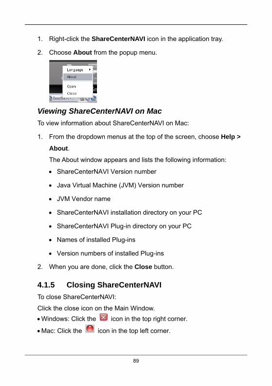
1. Right-click the ShareCenterNAVI icon in the application tray.
2. Choose About from the popup menu.
Viewing ShareCenterNAVI on Mac
To view information about ShareCenterNAVI on Mac:
1. From the dropdown menus at the top of the screen, choose Help >
About.
The About window appears and lists the following information:
ShareCenterNAVI Version number
Java Virtual Machine (JVM) Version number
JVM Vendor name
ShareCenterNAVI installation directory on your PC
ShareCenterNAVI Plug-in directory on your PC
Names of installed Plug-ins
Version numbers of installed Plug-ins
2. When you are done, click the Close button.
4.1.5 Closing ShareCenterNAVI
To close ShareCenterNAVI:
Click the close icon on the Main Window.
Windows: Click the icon in the top right corner.
Mac: Click the icon in the top left corner.
89

For Windows PCs, if you close ShareCenterNAVI this way, you can open it from the application tray icon.
Alternative Method for Windows
To close ShareCenterNAVI:
1. Right-click the ShareCenterNAVI icon in the application tray.
2. Choose Close from the popup menu.
If you close ShareCenterNAVI this way, you must open it from the Windows Start menu.
4.2 Managing Backups
Caution
Do not close the ShareCenterNAVI or log out the Windows PC while you are setting a scheduled backup or running a back-up.
4.2.1 Doing a Backup Now
This feature enables you to perform an immediate schedule backup of your files from your Windows or Mac to the NAS system (ShareCenterNAVI).
You can perform an immediate backup of your files from:
ShareCenterNAVI Main Window
ShareCenterNAVI Device List
ShareCenterNAVI tray icon (Windows PCs only)
One Touch Button
90

Main Window
If you do not have a backup schedule for your PC, start your backup from the ShareCenterNAVI Main Window.
1. Go to the Main Window.
2. Click the SmartSYNC icon.
3. Click the Backup button.
4. Under Backup your data to, choose:
The NAS or Local drive (your PC or MAC) from the first dropdown
menu.
The letter designation of your PC or MAC drive under the second
dropdown menu.
5. Do any of the following actions to select your backup folders:
Check the Backup My Data box – Selects the My Documents,
Favorites, and Desktop folders with all their contents.
Click the Add to Backup icon – Opens the My Documents
folder. Click a folder you want to back up, then click the Choose
button. Repeat for additional folders.
Drag and drop the folders you want to back up to the Backup your
data from window.
6. Click the Backup button.
The backup begins immediately.
Device List
Before you can do a back-up from the ShareCenterNAVI Main Window, you must create a backup schedule.
91

1. Go to the Main Window.
2. Right-click the system in the Device List whose backup you want to
run.
3. Choose the Backup Now option.
The backup begins immediately.
Tray Icon
Before you can do a backup from the ShareCenterNAVI tray icon, you must create a backup schedule and setup default NAS first. This feature applies to Windows PCs only.
1. Right-click the ShareCenterNAVI icon in the application tray.
2. Choose Backup Now in the popup menu.
The backup begins immediately.
The amount of time required depends on the size and number of files being backed up.
The backed up files appear on the NAS system in ShareCenterNAVI in a folder named BACKUPDATA_your username.
You can restore the backup files to your PC at any time.
92

4.2.2 Scheduling a Backup
You can schedule backups by the hour, day, or week.
To set a schedule for backing up files from your PC to the NAS system:
1. Go to the Main Window.
2. Click the SmartSYNC icon.
3. Click the Backup button.
4. Under Backup your data to, choose
The NAS or Local drive (your PC or MAC) from the first dropdown
menu.
The letter designation of your PC or MAC drive under the second
dropdown menu.
5. Do any of the following actions to select your backup folders.
Check the Backup My Data box – Selects the My Documents,
Favorites, and Desktop folders with all their contents.
Click the Add to Backup icon – Opens the My Documents
folder. Click a folder you want to backup, and then click the
Choose button. Repeat for additional folders.
Drag and drop the folders you want to back up to the Backup your
data from window.
6. Click the Schedule button.
7. Click an option button for
Hour
93

94
Day
Day of the week
8. Choose the corresponding values from the dropdown menus:
Number of hours
Time of day in hours and minutes
Time of day and day of the week
9. Click the Add button.
The newly created schedule appears in the Schedule List.
The backed up files will appear on the NAS in a folder named BACKUPDATA_your username.
You can also click the Start button to run a scheduled backup immediately.
4.2.3 Viewing Backup Schedules
To view the list of current schedules:
1. Go to the Main Window.
2. Click the SmartSYNC icon.
3. Click the Schedule List button.
The list of all backup schedules appears.
4.2.4 Changing a Scheduled Backup
You can schedule backups by the hour, day, or week.
To change the scheduled backup of files from your PC to the NAS system:
1. Go to the Main Window.
2. Click the SmartSYNC icon.
3. Click the Schedule List button.

4. Click the schedule you want to change.
5. Click the Modify button.
6. Click the folder whose contents you want to backup.
7. Click the Add to Backup icon to expand the tree and narrow
your choices.
8. Click the Schedule button.
9. Click an option button for
Hour
Day
Day of the week
10. Choose the corresponding values from the dropdown menus:
Number of hours
Time of day in hours and minutes
Time of day and day of the week
11. Click the Add button.
The modified schedule appears in the Schedule List.
You can also click the Start button to run a scheduled backup immediately.
4.2.5 Deleting a Scheduled Backup
Deleting a scheduled backup has no effect upon any files previously backed-up to the NAS system.
To delete a scheduled backup:
1. Go to the Main Window.
95

2. Click the SmartSYNC icon.
3. Click the Schedule List button.
4. Click the schedule you want to delete.
5. Click the Delete button.
6. Click the Yes button in the confirmation box.
4.2.6 Restoring Backed-up Files
You can restore all or any portion of the files in the BACKUPDATA_your username folder on the NAS system.
You can choose to restore the files to their original location or an alternative location.
The original file structure is maintained during backup and restoration.
Caution
If you restore to the original folders on your PC, the restore function will overwrite the files in those folders. Be careful which files you restore and where on your PC you direct the backup files.
To restore your backed-up files from the NAS system to your PC:
1. Go to the Main Window.
2. Click the SmartSYNC icon.
3. Click the Restore button.
4. Click the folder whose contents you want to restore.
5. Click the arrow icons to expand the tree and narrow your choices.
6. Click an option button.
Restore to original folder -- The backup files overwrite the files on
your PC
96
97
Restore to a specific folder -- No files are overwritten on your PC
7. If you chose Restore to a specific folder, do one of the following
actions.
Type the name of an existing folder in the field provided.
Type the name of a new folder in the field provided.
Click the Folder icon -- Opens the My Documents folder.
Click a folder you want to use for a target, then click the Open
button.
8. Click the Restore button.
9. Click the Yes button in the confirmation box.
The restoration begins immediately.
The amount of time required depends on the size and number of files being restored.
4.2.7 Viewing the Backup Event Log
Backup events report on backups, schedules, and file transfers.
Events are reported by date, time, severity (information or error) and description.
To view Backup Event Log:
1. Go to the Main Window.
2. Click the SmartSYNC icon.
3. Click the Event Log button.
4. Optional. Set the Event Filter dropdown menu to display.
All events
Information events only

Error events only
5. Optional. Click the arrow on the Date/Time header to reverse the
chronological order.
Note
For NAS system events, see “Viewing the System Event Log” on page 129.
4.2.8 Saving the Event Log
This function saves a copy of the Backup Event Log as a text file onto your PC.
The text file records the events displayed in the Event Log window.
Set the Event Filter dropdown menu to display:
All events
Information events only
Error events only
Click the arrow on the Date/Time header to reverse the chronological order.
Saving the Backup Event Log
To save a copy of the Backup Event Log as a text file:
1. Go to the Main Window.
2. Click the SmartSYNC icon.
3. Click the Event Log button.
4. Click the Save button.
5. Optional. Change the file name or save to a different location.
6. Click the Save button in the Save dialog box.
98

4.2.9 Clearing the Event Log
Note
Before you clear the Backup Event Log, consider saving a copy for future reference.
To clear the Backup Event Log:
1. Go to the Main Window.
2. Click the SmartSYNC icon.
3. Click the Event Log button.
4. Click the Clear All button.
5. Click the Yes button in the confirmation box.
4.2.10 Setting the Port
By using port setting, the public services like a WWW server or an FTP server, and others running on your private network may become accessible from the Internet.
To set the Port:
1. Go to the Main Window.
2. Click the SmartSYNC icon.
3. Click the Setting button.
4. Type the Port number in the field provided.
The default number is 873.
5. Click the OK button.
The setting begins immediately.
6. Click the OK button in the confirmation box.
99

4.3 Managing Share Folders
4.3.1 Opening a Share Folder
This feature opens share folders in the file browser.
Device List
To open a share folder from the Device List:
1. Right-click the system in the Device List whose share folders you
want to open.
2. Click Share Folders.
All share folders open in your PC’s file browser.
Main Window
To open a share folder from the Main Window:
1. Click the Share Folder icon.
2. Double-click the folder in the Share Folder List that you want to open.
The share folder opens in your PC’s file browser.
Tray Icon
To open a share folder from Tray Icon:
1. Right-click the ShareCenterNAVI icon in the application tray.
100

101
2. Choose Share Folder in the popup menu.
All share folders open in your PC’s file browser.
4.3.2 Viewing a List of Share Folders
To view a list of Share Folders:
1. Go to the Main Window.
2. Click the Share Folder icon.
3. Click the Share Folder List button.
The Share Folder List appears.
4. Double-click the individual share folder to view its contents.
4.3.3 Mounting a Share Folder / Creating a Network Drive
To mount a share folder or create a network drive (Windows):
1. Go to the Main Window.
2. Click the Share Folder icon.
3. Click the Mount Share Folder button.
4. Click the share folder you want to mount or make a network drive.
The folder name is highlighted.
5. Choose a device name (drive letter) from the dropdown menu.
6. Click the Mount button.
The share folder appears on your PC as a mounted or network drive.
4.3.4 Un-mounting a Share Folder / Disconnecting a Network Drive
To un-mount a share folder or disconnect a network drive (Windows):
1. Go to the Main Window.

102
2. Click the Share Folder icon.
3. Click the Mount Share Folder button.
4. Click the share folder you want to un-mount or delete as a network
drive.
The folder name is highlighted.
5. Click the Un-Mount button.
6. Click the Yes button in the confirmation box.
The share folder is un-mounted or disconnected but the link remains.
4.3.5 Setting up a Share Folder for Time Machine
Time Machine is a backup utility included with Mac OS X 10.5 “Leopard” or higher.
Before you begin, be sure your Mac is running and connected to the same network as the NAS system.
In ShareCenterNAVI
To set up a NAS system folder for Time Machine backups:
1. Go to the Main Window.
2. Click the Share Folder icon.
3. Click the Mount Share Folder button.
4. Click the share folder you want to use for Time Machine backups.
5. Check the Support TimeMachine box.
6. Click the Mount button.
A message appears, “This folder has been set to a network drive.”
103
On the Mac, Time Machine NOT configured
Follow this procedure if you have not set up Time Machine.
To set up the Mac for backups with NAS system:
1. On the desktop, go to the Dock and click the Time Machine icon.
A popup message informs you that no storage location is set up.
2. In the popup message, click the Set Up Time Machine button.
3. In the Time Machine dialog box, click the Choose Backup Disk...
button.
4. In the list of external drives, choose the share folder that you
mounted on the NAS system and click the Use for Backup button.
5. In the Name and Password dialog box, enter your user name and
password for NAS system, then click the Connect button.
On the Mac, Time Machine Configured
Follow this procedure if you currently have a Time Machine configuration.
To set up the Mac for backups with NAS system:
1. On the desktop, go to the Dock and click the Time Machine icon.
2. In the Time Machine dialog box, click the Change Disk... button.
3. In the list of external drives, choose the share folder that you
mounted on the NAS system and click the Use for Backup button.
4. In the Name and Password dialog box, enter your user name and
password for NAS system, then click the Connect button.
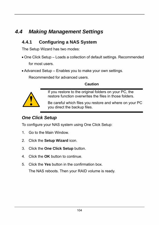
4.4 Making Management Settings
4.4.1 Configuring a NAS System
The Setup Wizard has two modes:
One Click Setup – Loads a collection of default settings. Recommended
for most users.
Advanced Setup – Enables you to make your own settings.
Recommended for advanced users.
Caution
If you restore to the original folders on your PC, the restore function overwrites the files in those folders.
Be careful which files you restore and where on your PC you direct the backup files.
One Click Setup
To configure your NAS system using One Click Setup:
1. Go to the Main Window.
2. Click the Setup Wizard icon.
3. Click the One Click Setup button.
4. Click the OK button to continue.
5. Click the Yes button in the confirmation box.
The NAS reboots. Then your RAID volume is ready.
104

105
Advanced Setup
To configure your NAS system using Advanced Setup:
1. Go to the Main Window.
2. Click the Setup Wizard icon.
3. Click the Advanced Setup button.
4. Choose Automatic (DHCP) or Manual network settings.
5. If you chose Manual settings, type entries for each of the following
parameters in the fields provided.
Computer (NAS system) Name
IP Address
Subnet Mask
Gateway
Primary and Secondary DNS – optional
Click the Next button to continue.
6. Choose the following values from their respective dropdown menus.
Timezone
Year
Month
Day
Time in Hours, Minutes, and Seconds
Click the Next button to continue.
7. Choose Automatic or Manual RAID Volume creation.

106
8. If you chose Manual, choose the type of RAID Volume you want.
Maximum Capacity and performance - RAID 0, using all physical
drives
Data Protection - RAID 5, using all physical drives
Click the Next button to continue.
9. Choose a network drive letter from the dropdown menu.
The drive is mapped as a network drive on your PC.
The list begins with Z and goes in reverse alphabetical order.
Click the Next button to continue.
10. Review your parameters.
To make changes, click the Previous button.
To accept the parameters and configure your NAS system, click
the OK button.
11. Click the Yes button in the confirmation box.
The NAS reboots. Your RAID volume is ready.
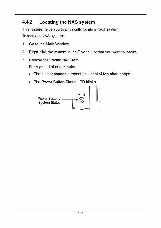
4.4.2 Locating the NAS system
This feature helps you to physically locate a NAS system.
To locate a NAS system:
1. Go to the Main Window.
2. Right-click the system in the Device List that you want to locate.
3. Choose the Locate NAS item.
For a period of one minute:
The buzzer sounds a repeating signal of two short beeps.
The Power Button/Status LED blinks.
Power Button /System Status
107

108
4.4.3 Wake-on-LAN
This feature allows you to turn on or wake up the NAS system by locate a NAS system.
To wake up a NAS system:
1. Go to the Main Window.
2. Right-click the system in the Device List that you want to wake up.
3. Choose the Locate NAS option.
It takes about a minute to boot the NAS system. When fully booted:
The System Status LED turns blue.
The buzzer beeps one time.
4.4.4 Choosing a Default NAS System
This feature sets the default NAS system (NAS system) for the Main Window and ShareCenterNAVI tray icon. A default NAS activates several important functions, including:
Share Folder -- Opening a Share Folder
Backup Now -- Performing an Immediate Backup
Open Advanced Management -- Starting the Advanced Storage
Manager
Event Notice -- Enabling Event Notification
If you do not choose a default NAS, ShareCenterNAVI sets the default NAS after you first log on.

Setting the default NAS
To set a default NAS:
1. Go to the Main Window.
2. Right-click the system in the Device List that you want to make the
default.
3. Choose the Default NAS option.
The default NAS is highlighted in the Device List.
4.4.5 Viewing the System Event Log
NAS events report functions and status of the NAS system. The Event Log displays the 20 most recent events.
Events are reported by date, time, severity (information or warning) and description.
To view the NAS system is Event Log:
1. Go to the Main Window.
2. Click the Smart SYNC icon.
3. Click the Event Log button.
Click the arrow on the Date/Time header to reverse the chronological order.
109

4.4.6 Installing Plug-ins
1. Go to the Main Window.
2. Click the NAS Management icon.
3. Click the Configure Plugin button.
The newly added plug-in appears in the list. Its Service Status is OFF.
4. Click the plug-in to choose it.
The plug-in’s name is highlighted.
5. Click the Enable button.
After a moment, the Service Status changes to ON.
The plug-in is now installed NAS system.
Warning
Do not disconnect the power or shut down the NAS system while the plug-in installation is running!
4.4.7 Viewing a List of Plug-ins
To view a list of installed plug-ins:
1. Go to the Main Window.
2. Click the NAS Management icon.
3. Click the Configuration Plug-in button.
Currently installed plug-ins appear in the Configuration Plug-in list.
110

4.4.8 Viewing Plug-in Version Numbers
To view plug-in version numbers in Windows:
1. Right-click the ShareCenterNAVI icon in the application tray.
2. Choose About from the popup menu.
The About window appears. The About window includes a list of installed plug-ins and their version numbers.
3. When you are done with the About window, click the Close button.
4.4.9 Enabling and Disabling Plug-ins
Enabling Plug-ins
You must add a plug-in to NAS system before you can use this function.
To enable a plug-in:
1. Go to the Main Window.
2. Click the NAS Management icon.
3. Click the Configuration Plug-in button.
4. Click the Plug-in you want to enable.
The plug-in is highlighted.
111

112
5. Click the Enable button.
After a moment, the Service Status changes to ON.
The plug-in is now enabled on NAS system.
Disabling Plug-ins
Disabling a plug-in saves memory space and processing time on the NAS system. If you do not use a feature, consider disabling its plug-in.
To disable a plug-in:
1. Go to the Main Window.
2. Click the NAS Management icon.
3. Click the Configuration Plug-in button.
4. Click the Plug-in you want to disable.
The plug-in is highlighted.
5. Click the Disable button.
After a moment, the Service Status changes to OFF.
The plug-in is now disabled.
4.4.10 Removing Plug-ins
There are two reasons to remove a plug-in:
To replace the old plug-in with a new one.
You know that you will never use the plug-in.
Removing Plug-ins
To remove a plug-in:
1. Go to the Main Window.
2. Click the NAS Management icon.
3. Click the Configuration Plugin button.
4. Click the Plug-in you want to remove.

113
The plug-in is highlighted.
5. Click the Remove button.
6. Click the Yes button in the confirmation box.
The plug-in is removed from ShareCenterNAVI.
4.4.11 Rebooting the NAS System
Normally you only need to reboot the NAS system is after a firmware upgrade or a plug-in installation.
During the reboot, none of your folders are accessible from your networked PCs.

To reboot the NAS system:
1. Go to the Main Window.
2. Click the NAS Management icon.
3. Click the Shutdown button.
4. Click the Restart option.
5. Click the OK button.
The reboot runs automatically.
When the NAS system is fully booted:
The system status LED turns blue
The buzzer beeps one time (if the buzzer is enabled)
Power Button /System Status LED
114

4.4.12 Shutting Down the NAS system
The only time you need to shut down the NAS system is to replace the cooling fan or the power supply.
During and after the shutdown, none of your folders are accessible from your networked PCs.
To shut down the NAS system:
1. Go to the Main Window.
2. Click the NAS Management icon.
3. Click the Shutdown button.
4. Click the Shutdown option.
5. Click the OK button.
The shutdown runs automatically.
The system status LED turns red, and then goes dark.
Power Button /System Status LED
115

116
Chapter 5: Licensing and Support
GNU General Public License This product includes copyrighted third-party software licensed under the terms of the GNU General Public License. Please see the GNU General Public License (“GPL”) for the exact terms and conditions of this license at http://www.gnu.org.
Subject to GPL, you may re-use, re-distribute and modify the GPL source code. Note that with respect solely to the GPL Software, no warranty is provided and we do not offer direct support for the distribution.
Technical Support If you experience problems with setup or use of your DNS-1250-04 or DNS-1250-06 NAS system, please contact technical support before attempting to return the product.
D-Link support web site: http://www.dlink.com