use of pbee in the design practice - reluis · use of pbee in the design practice marko schotanus...
TRANSCRIPT

Use of PBEE in the Design Practice
Marko Schotanus
RUTHERFORD & CHEKENE
Marko SchotanusJuly 2009

Outline When is PBEE used in design practice?
PBD of Tall Buildings
Elastic analysis
Effective stiffness properties
Damping
RUTHERFORD & CHEKENE
Damping
Nonlinear Modeling
Component models and acceptance criteria
Capacity Design
Dynamic amplification and system effects

PBEE in Practice
Existing Structures
- Standardized in ASCE 41-06 (supplement 1)
- Incorporated in Chapter 34 of 2006 IBC
- Innovative materials/systems
- More specific performance objectives
RUTHERFORD & CHEKENE
- More specific performance objectives
New Structures
- Justification of lower demands/higher capacities
- Innovative materials/systems
…use fancy analysis to do something the code won’t allow…

Advantages
Fast adoption of new materials and systems
Immediate incorporation of state-of-the-art modeling
RUTHERFORD & CHEKENE
Expert review
Tailor made structures

Disadvantages
Increases design time and cost
Analysis intensive
Inconsistent design criteria for similar buildings
RUTHERFORD & CHEKENE
buildings
Convincing local autorities
Mediation with(in) Peer review teams
Designers are working against a “moving target”

RUTHERFORD & CHEKENE
Beyond ASCE-41

Incremental Dynamic Response
1.5
2.0
2.5
Sa
(g
)
Static PO
IDA-16%
IDA-50%
IDA-84%
capacity1.5
2.0
2.5
Sa
(g
)
Static PO
IDA-16%
IDA-50%
IDA-84%
capacity
RUTHERFORD & CHEKENE
Existing Retrofitted
0.0
0.5
1.0
0.0% 0.5% 1.0% 1.5% 2.0% 2.5% 3.0% 3.5%
Roof Drift
Sa
(g
)
0.0
0.5
1.0
0.0% 0.5% 1.0% 1.5% 2.0% 2.5% 3.0% 3.5%
Roof DriftS
a (
g)

Advanced Seismic Assessment Method
RUTHERFORD & CHEKENE

Advanced Seismic Assessment Method
R&C has applied the method to a range of different building types:
• Electrical
RUTHERFORD & CHEKENE
• Electrical substations, office buildings, parking and maintenance facilities
• 1-story –8-stories
•

Acknowledgements
Karl Telleen
Joe Maffei
RUTHERFORD & CHEKENE

PBD of Tall Buildings
RUTHERFORD & CHEKENE

What’s Different about these Buildings?
High-performance materials
Framing systems not satisfying code prescriptive limits
Non-prescriptive designs are
RUTHERFORD & CHEKENE
Non-prescriptive designs are accepted in the code by demonstrating at least equivalent seismic performance.
CBC 1629.10.1, 1605.2, 104.2.8after MKA

Technical Basis for Height Limits
Limit height for systems that can develop story mechanisms
Favor systems that distribute inelastic energy dissipation over
RUTHERFORD & CHEKENE
inelastic energy dissipation over the height of the building.

What is “Equivalent” Performance?
Consider both the intended performance of
the code and the performance of a
typical good prescriptive design.
Equivalence to poorly-performing but code-
RUTHERFORD & CHEKENE
Equivalence to poorly-performing but code-
prescriptive buildings should not be
acceptable.
Use Seismic Peer Review.
RUTHERFORD & CHEKENE

RUTHERFORD & CHEKENE

RUTHERFORD & CHEKENE

RUTHERFORD & CHEKENE

RUTHERFORD & CHEKENE

Washington Mutual / Seattle Art Museum
RUTHERFORD & CHEKENE
SEOR: Magnusson Klemencic Associates Seattle

Limitations of the Building Code
High-performance materials
Building systems with height limits or not addressed
Higher mode effects
RUTHERFORD & CHEKENE
Higher mode effects
Preclude a story mechanism in moment frames
Shear amplification
Damping
Explicit Performance Objectives
How Consistent are Design Criteria?
SEAONC PBD of Tall Buildings committee
compared design criteria for tall
buildings.
10 tall buildings on West Coast of USA,
RUTHERFORD & CHEKENE
10 tall buildings on West Coast of USA,
designed by 6 firms.

SEAONC Committee
Brian Dean, Rafael Sabelli (Walter P. Moore)
Jason Krolicki (chair), Michael Willford, Ibbi Al-Mufti, Damian Grant (ARUP)
Derrick Roorda, Nic Rodrigues (DeSimone Consulting Eng.)
Ron Klemencic
RUTHERFORD & CHEKENE
Ron Klemencic (Magnusson Klemencic Associates)
Neville Mathias, Mahmoud Hachem (Skidmore, Owings & Merrill)
Michael Gemmill (Nabih Youssef Associates)
Mark Moore (ZFA Structural Engineers)
Saeed Fathali (Rutherford & Chekene)

How Consistent are Design Criteria?
10 tall buildings on West Coast of USA,
designed by 6 firms.
San Francisco, Seattle, Los Angeles
RUTHERFORD & CHEKENE
>240ft, five well over 500ft
Ductile, coupled reinforced concrete shear
walls (combined with moment frames,
outriggers, and megabraces)

Areas of Consensus
Wind tunnel testingProvisions for nonstructural componentsPerformance objectivesAnalysis proceduresExtent of three-dimensional modeling
RUTHERFORD & CHEKENE
Extent of three-dimensional modelingDesign seismic hazard levelsNumber of ground motion pairs used for NLRH analysis
Ground motion orientation relative to building
Inter-story drift limits

Items with Highest ScatterDamping specificationFlipping of ground motion pairsBackstay effectElastic stiffness modifiersComponent models for NLRH analysis
RUTHERFORD & CHEKENE
Component models for NLRH analysisAcceptance criteriaForce levels used to evaluate acceptance criteria

Two-Step DesignDetermine the strengths at nonlinear locations
using the building code requirements
• Code (DBE) level earthquake ÷ R factor
• Minimum base shear
All other actions are designed to remain elastic
RUTHERFORD & CHEKENE
All other actions are designed to remain elastic
under MCE level ground motions:
• Wall shear, shear friction, wall flexure outside of intended yield locations, floor and roof diaphragms and collectors and connections, foundation perimeter walls, etc.

Linear-Elastic Analysis
RUTHERFORD & CHEKENE

Effective Stiffness
Reduction by Reff
475y NL
475y linear response
RUTHERFORD & CHEKENERoof Displacement
2475y NL response
by Reff
Vmin
475y NL response

Effective Stiffness
RUTHERFORD & CHEKENE
Distribution of Effective Stiffness Values Used for Concrete Core Shear Walls

EFFECTIVE STIFFNESS

UCSD wall Elastic ETABS model
RUTHERFORD & CHEKENERUTHERFORD & CHEKENE

2000
4000
6000
8000
10000
Base M
om
en
t [k
ip-f
t]Experimental results
EQ3:
Essentially
linear
RUTHERFORD & CHEKENE
-10000
-8000
-6000
-4000
-2000
0
-17.5 -12.5 -7.5 -2.5 2.5 7.5 12.5 17.5
Roof Displacement [in]
Base M
om
en
t [k
ip-f
t]
EQ4: Non-linear

EQ3
2
4
6
8
Ro
of
Dis
pla
cem
en
t [i
n]
Wall: Eeff = 0.2Ec
Slab: Eeff = 0.1Ec
RUTHERFORD & CHEKENERUTHERFORD & CHEKENE
-8
-6
-4
-2
0
40 45 50 55 60
Time [s]
Ro
of
Dis
pla
cem
en
t [i
n]
UCSD Test
ETABS

EQ3
Wall: Eeff = 0.2Ec
Slab: Eeff = 0.1Ec
700
800
700
800
Experiment
ETABS
Mwall
700
800
Experiment
ETABS
RUTHERFORD & CHEKENERUTHERFORD & CHEKENE
0
100
200
300
400
500
600
0 5 10 15 20
Lateral Displacement [in]
Bu
ild
ing
He
igh
t [i
n]
Experiment
ETABS
0
100
200
300
400
500
600
0 2000 4000 6000 8000 10000
System Moment [kip-ft]
Bu
ild
ing
He
igh
t [i
n]
Mwall
Mn,exp
0
100
200
300
400
500
600
0 100 200 300
System Shear Force [kip]
Bu
ild
ing
He
igh
t [i
n]

2
4
6
8
Ro
of
Dis
pla
ce
me
nt
[in
]EQ3
Wall: Eeff = 0.8Ec
Slab: Eeff = 0.5Ec
RUTHERFORD & CHEKENE
-8
-6
-4
-2
0
2
40 45 50 55 60
Time [s]
Ro
of
Dis
pla
ce
me
nt
[in
]
UCSD Test
ETABS
RUTHERFORD & CHEKENE

Effective Stiffness
RUTHERFORD & CHEKENE
Effective Stiffness Values Used for Coupling Beams Together with Related Core Wall Values

Damping
Measured damping ratio vs building height
6
7
8
9
10
Dam
pin
g r
ati
o (
%)
Buildings, Steel
Buildings, SRC
Buildings, RC
Chimneys, RC
RUTHERFORD & CHEKENE
0
1
2
3
4
5
0 50 100 150 200 250 300 350 400 450
Height [m]
Dam
pin
g r
ati
o (
%)
Measured Damping Ratio vs Building Height (Satake et al.)

Nonlinear Modeling
RUTHERFORD & CHEKENE

Effective Stiffness
Element Effective Stiffness Value
RUTHERFORD & CHEKENE
Element
Core Walls 0.3 0.8 0.5 0.25 0.8 0.9
Basement Walls 0.2 / 0.5 1.0 0.3 / 1.0 0.5 / 1.0 1.0 0.5
Diaphragms* 0.2 / 0.5 0.25 0.3 / 1.0 0.1 / 0.7 0.5 0.5

2
4
6
8
10
Sh
ear
Fo
rce,
kip
s
Coupling Beam C8(0.50Ig, 0.15 EnergyFactor, Nominal Strength with ΩΩΩΩ0, FEMA strength
degradation)Test-…
Component Models
RUTHERFORD & CHEKENE
-10
-8
-6
-4
-2
0
2
-3 -2 -1 0 1 2 3
Sh
ear
Fo
rce,
kip
s
Deflection, in.

2
4
6
8
10
Sh
ear
Fo
rce,
kip
sCoupling Beam C8
(0.22Ig, LinearEnergyFactor, Expected strength)
Test-…
Component Models
RUTHERFORD & CHEKENE
-10
-8
-6
-4
-2
0
2
-3 -2 -1 0 1 2 3
Sh
ear
Fo
rce,
kip
s
Deflection, in.

Acceptance Criteria
RUTHERFORD & CHEKENE
Conventional Coupling Beam Rotation Limits
Diagonally Reinforced Coupling Beam Rotation Limits

Blind Prediction Results - EQ3 - Shear Force Envelope
First 4 teams of each category
5
6
7
Measured
UCSD test blind prediction
RUTHERFORD & CHEKENE
0
1
2
3
4
0 50 100 150 200 250 300 350
Shear Force (kips)
Flo
or

200
250
300
350
Bu
ild
ing
Heig
ht
[ft]
R&C_MAX_X
R&C_MAX_Y
EOR_MAX_X
EOR_MAX_Y
Effect of Modeling on Results
0
50
100
150
0.00% 0.20% 0.40% 0.60% 0.80% 1.00% 1.20% 1.40% 1.60% 1.80% 2.00%
Inter-Story Drift Ratio [%]
Bu
ild
ing
Heig
ht
[ft]

Plastic analysis – SEAOC seismic design examples, Volume 3
RUTHERFORD & CHEKENE

Capacity Design
RUTHERFORD & CHEKENE
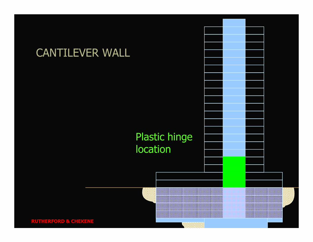
CANTILEVER WALL
RUTHERFORD & CHEKENE
Plastic hinge location
RUTHERFORD & CHEKENE
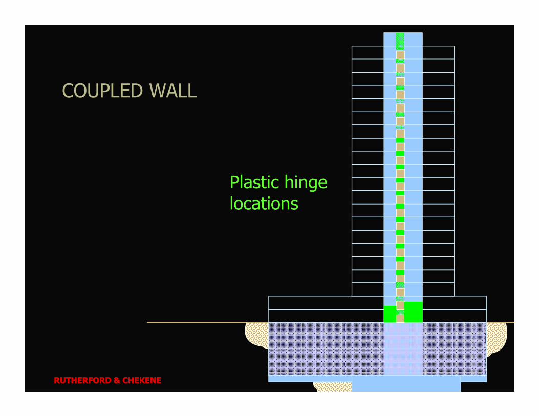
COUPLED WALL
Plastic hinge locations
RUTHERFORD & CHEKENE
locations
RUTHERFORD & CHEKENE
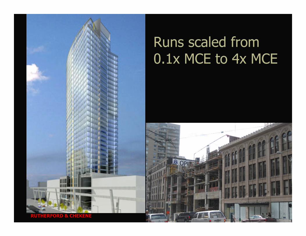
Runs scaled from 0.1x MCE to 4x MCE
RUTHERFORD & CHEKENE

IDA Demands
750000
1000000
1250000
1500000
1750000
2000000
Pe
ak
Co
re M
om
en
t a
bo
ut
H1
(k
ip-f
t) maximum base moment versus maximum lateral roof displacement in the H1 direction (Stronger core direction)
RUTHERFORD & CHEKENE
0
250000
500000
750000
1000000
1250000
1500000
1750000
2000000
0 5 10 15 20 25 30 35 40 45
Peak Roof Displacement (ft)
Pe
ak
Co
re M
om
en
t a
bo
ut
H2
(k
ip-f
t)
IDA H1@7th
IDA H1@1st
MCE level
0
250000
500000
0 5 10 15 20 25 30 35 40 45
Peak Roof Displacement (ft)
Pe
ak
Co
re M
om
en
t a
bo
ut
H1
(k
ip-f
t)
IDA H2@7th
IDA H2@1st
MCE
level
direction)
maximum base moment versus maximum roof displacement in the H2 direction (Weaker core direction)

0.4
0.5
0.6
0.7
0.8
0.9
1.0
No
rma
lize
d E
ffe
cti
ve
He
igh
t (M
/V)/
H
IDA H1@7th
IDA H1@1st
IDA H2@7th
MCE level
Moment to Shear Ratio2/3
1/2
RUTHERFORD & CHEKENE
0.0
0.1
0.2
0.3
0.4
0 1 2 3 4
Ground-Motion Scale Factor
No
rma
lize
d E
ffe
cti
ve
He
igh
t (M
/V)/
H
Variation of location of resultant lateral force with increasing intensity

0
50
100
150
200
250
300
350
400
450
500
0 5000 10000 15000 20000 25000 30000 35000
Core Shear Force H1 (kips)
Bu
ild
ing
He
igh
t (f
t)
1.00xCC067
1.25xCC067
1.50xCC067
1.75xCC067
2.00xCC067
Capacity
Full Capacity
Preventing Shear Failure
RUTHERFORD & CHEKENE
Core Shear Force H1 (kips)
0
50
100
150
200
250
300
350
400
450
500
0 5000 10000 15000 20000 25000 30000 35000
Core Shear Force H2 (kips)
Bu
ild
ing
He
igh
t (f
t)
1.00xCC067
1.25xCC067
1.50xCC067
1.75xCC067
2.00xCC067
Capacity
Full Capacity
Incrementally-scaled NLRH analyses results in terms of maximum story shear force in both H1 (left) and H2 (right) directions, together with shear capacity

250
300
350
400
450
500
Bu
ild
ing
Heig
ht
(ft)
Yielding Outside Hinge Zone
RUTHERFORD & CHEKENE
0
50
100
150
200
-0.01 0 0.01 0.02 0.03
Strain in Corner N
Bu
ild
ing
Heig
ht
(ft)
Strain Profile over the Building Height at Different Time Steps

Tall Buildings Initiative
Initiative to advance design of tall buildings
Main participants
• PEER, SCEC, USGS, SFDBI, LADBS, FEMA
• ATC, LATBSDC, SEAOC, SEAONC
• Project Management Committee (T-PAC)
RUTHERFORD & CHEKENE
• Project Management Committee (T-PAC)– J. Moehle, Y. Bozorgnia
– N. Abrahamson, M. Lew, P. Somerville
– R. Hamburger, H. Krawinkler, M. Moore, F. Naeim
– R. Lui

Practice Needs (from PEER)
Structural DesignMinimum base shearCapacity design factorsInherent slab-outrigger effectStory mechanism protectionWall shear strengthEffective damping in NLRH analysisOther NLRH assumptions
• Applicable ground motions– (e.g., T = 9 sec)
• Ground motion scaling
• Input motions for subterranean levels
• Performance objectives
RUTHERFORD & CHEKENE
Other NLRH assumptionsEffective elastic stiffnessPodium force transferRational drift limitsP-delta modelingConcrete slab to core wall connectionsSteel framing to core wall connectionsDeep mat slab behaviorDual system requirements

Guidelines for Modeling and Acceptance CriteriaCore group – J. Malley, G. Deierlein, H. Krawinkler, J. Maffei, M.
Pourzanjani and J. Wallace
Approach: Workshop to identify key issues, assignments to experts to develop principles, procedures, and values.
• Key issues:– Basic principles, including capacity design
RUTHERFORD & CHEKENE
– Basic principles, including capacity design– General modeling issues (e.g., effective damping)
– Podium force transfer– Modeling of various systems and elements (core walls, frames, coupling beams, etc.)
– Foundation modeling (with Task 8)

Closing Remarks
Little focus on risk in practical applications of PBEE
Need for better guidelines (… or better enforcement?)
RUTHERFORD & CHEKENE
enforcement?)
Focus on better understanding of relation between parameters on performance of final product
Verify performance of existing structures