use and maintenance manual - autoequip
TRANSCRIPT
SILENT, ROTATING, ELECTRIC - SCREW COMPRESSORS• USE AND MAINTENANCE MANUAL• SAFETY WARNINGS
GSE 5.5 HP - 7.5 HP - 10 HP
04/2015 - Rev 00 - english


GSE 5.5 HP - 7.5 HP - 10 HP
3USE AND MAINTENANCE MANUAL • GSE 5.5 HP - 7.5 HP- 10 HP • REV. 00
CONTENTS1 GENERAL INFORMATION ................................................................................................. 4
1.1 Warnings and care ....................................................................................................... 41.2 How to use the manual ................................................................................................ 41.3 CE marking .................................................................................................................. 51.4 Symbols ....................................................................................................................... 51.5 Maintenance and servicing information ....................................................................... 51.6 General safety warnings .............................................................................................. 6
2 COMPRESSOR TECHNICAL DATA .................................................................................... 82.1 Overall dimensions ...................................................................................................... 9
3 UNPACKING ..................................................................................................................... 10
4 POSITIONING .................................................................................................................. 104.1 Positioning the compressor ........................................................................................11
5. BEFORE START-UP ......................................................................................................... 125.1 Using the compressor ............................................................................................... 125.2 Lubricating the compressor ....................................................................................... 125.3 Using the compressor with synthetic base oil ............................................................ 135.4 Connecting the compressor to the electricity supply.................................................. 145.5 Connecting the compressor power cable ................................................................... 155.6 Connecting the compressor to the pneumatic supply ................................................ 15
6 FIRST START-UP .............................................................................................................. 16
7 THERMAL RELAY CALIBRATION INFORMATION ........................................................... 17
8 ELECTRO-PNEUMATIC CIRCUIT DIAGRAM AND COMPONENT DESCRIPTION .......... 18
9 MAINTENANCE ................................................................................................................ 199.1 Tensioning the belts................................................................................................... 209.2 Suction pre-filter maintenance and replacement ....................................................... 219.3 Replacing the oil filter ................................................................................................ 229.4 Replacing the de-oiling filter ...................................................................................... 229.5 Oil change ................................................................................................................. 239.6 Replacing the air filter ............................................................................................... 23
10 COMPRESSOR MAINTENANCE CHECK SHEET .......................................................... 24
11 SPARE PARTS ................................................................................................................ 2511.1 Body ......................................................................................................................... 2611.2 Motor ........................................................................................................................ 2811.3 Suction valve ............................................................................................................ 3011.4 Fan-tank assembly ................................................................................................... 3211.5 Connections ............................................................................................................. 34
12 ELECTRIC DIAGRAMS ................................................................................................... 3712.1 List of components 4 - 5.5 - 7.5 kW electric diagrams .............................................. 38
Electric diagram 4 kW (1 of 4) ................................................................................. 39Electric diagram 4 kW (2 of 4) ................................................................................. 40Electric diagram 4 kW (3 of 4) ................................................................................. 41Component description 4 kW (4 of 4) ...................................................................... 42Electric diagram 5.5 kW (1 of 4) .............................................................................. 43Electric diagram 5.5 kW (2 of 4) .............................................................................. 44Electric diagram 5.5 kW (3 of 4) .............................................................................. 45Component description 5.5 kW (4 of 4) ................................................................... 46Electric diagram 7.5 kW (1 of 4) ............................................................................... 47Electric diagram 7.5 kW (2 of 4) ............................................................................... 48Electric diagram 7.5 kW (3 of 4) ............................................................................... 49Component description 7.5 kW (4 of 4) .................................................................... 50
4 kW
5.5 kW
7.5 kW
GSE 5.5 HP - 7.5 HP - 10 HP
4 USE AND MAINTENANCE MANUAL • GSE 5.5 HP - 7.5 HP- 10 HP • REV. 00
1 GENERAL INFORMATION
1.1 Warnings and care
1.2 How to use the manual
The compressor must be used exclusively in compliance with the instructions given in this manual, which must be stored carefully in an easily accessible place, available to the operators for the whole working life of the machine. Always indicate the model and serial number in any requests.
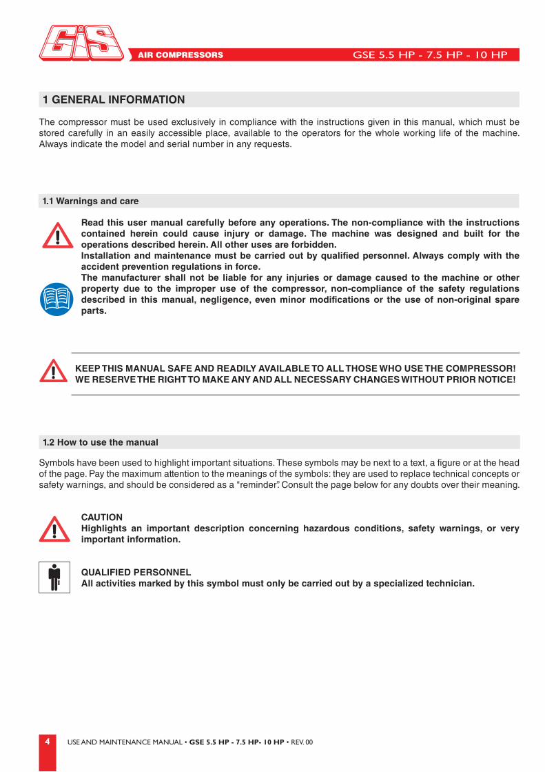
Read this user manual carefully before any operations. The non-compliance with the instructions contained herein could cause injury or damage. The machine was designed and built for the operations described herein. All other uses are forbidden.Installation and maintenance must be carried out by qualified personnel. Always comply with the accident prevention regulations in force.The manufacturer shall not be liable for any injuries or damage caused to the machine or other property due to the improper use of the compressor, non-compliance of the safety regulations described in this manual, negligence, even minor modifications or the use of non-original spare parts.
CAUTIONHighlights an important description concerning hazardous conditions, safety warnings, or very important information.
QUALIFIED PERSONNELAll activities marked by this symbol must only be carried out by a specialized technician.
Symbols have been used to highlight important situations. These symbols may be next to a text, a figure or at the head of the page. Pay the maximum attention to the meanings of the symbols: they are used to replace technical concepts or safety warnings, and should be considered as a "reminder”. Consult the page below for any doubts over their meaning.
KEEP THIS MANUAL SAFE AND READILY AVAILABLE TO ALL THOSE WHO USE THE COMPRESSOR!WE RESERVE THE RIGHT TO MAKE ANY AND ALL NECESSARY CHANGES WITHOUT PRIOR NOTICE!
GSE 5.5 HP - 7.5 HP - 10 HP
5USE AND MAINTENANCE MANUAL • GSE 5.5 HP - 7.5 HP- 10 HP • REV. 00
1.3 CE marking
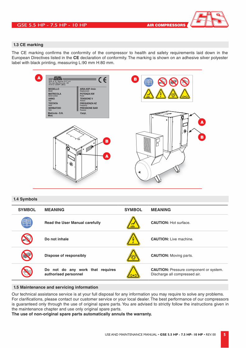
The CE marking confirms the conformity of the compressor to health and safety requirements laid down in the European Directives listed in the CE declaration of conformity. The marking is shown on an adhesive silver polyester label with black printing, measuring L:90 mm H:80 mm.
1.5 Maintenance and servicing information
Our technical assistance service is at your full disposal for any information you may require to solve any problems. For clarifications, please contact our customer service or your local dealer. The best performance of our compressors is guaranteed only through the use of original spare parts. You are advised to strictly follow the instructions given in the maintenance chapter and use only original spare parts.The use of non-original spare parts automatically annuls the warranty.
1.4 Symbols
SYMBOL MEANING SYMBOL MEANING
Read the User Manual carefully CAUTION: Hot surface.
Do not inhale CAUTION: Live machine.
Dispose of responsibly CAUTION: Moving parts.
Do not do any work that requires authorised personnel
CAUTION: Pressure component or system. Discharge all compressed air.
GIS di G. Sgarbi & C srlVia dei Barrocciai , 2941012 CARPI (MO)
MODELLOModel
MATRICOLASerial number
ANNOYear
TESTATAHead
SERBATOIOTank
Matricola - S.N.Mod.
Carpi,
ARIA ASP. l/minDisplacement
POTENZA KWPower
TENSIONE VTension
FREQUENZA HZFrequency
PRESSIONE BARPressure
A B
B
A
A
B

GSE 5.5 HP - 7.5 HP - 10 HP
6 USE AND MAINTENANCE MANUAL • GSE 5.5 HP - 7.5 HP- 10 HP • REV. 00
1.6 General safety warnings
1. Never place any parts of the body near the machine when in operation.
2. Never use the compressor with the guards removed. If maintenance requires the removal of any of the guards, prior to re-starting make sure that all the guards are correctly installed. It is strictly forbidden to disable any of the safety devices installed on the compressor.
3. Do not stick any objects or parts of the body into the protective grilles, to prevent physical injury or damage to the compressor.
4. Operate the compressor following the instructions given in this manual. Do not allow children or unauthorised personnel to use the compressor.
5. Always wear goggles or similar eye protection. Do not direct the air to any part of the body or towards other people.
6. Do not wear inappropriate clothing or accessories. If required, wear protective hair nets or hats.
7. The compressor must not be used by persons under the effect of alcohol, drugs or medicines which could cause drowsiness.
8. Before using the compressor, all staff must be familiar with all its functions and controls.
9. Never use the compressor for any purpose other than those described in this instruction manual.
10. Never direct the air jet towards persons or animals.
11. To avoid burns, do not touch the pipes, motor or any other hot parts.
12. Keep the work area around the compressor clean and well ventilated. Never use the compressor in an area near paints, solvents or combustible/explosive materials.
13. Check the outside of the compressor. If the power cable is damaged, repair or replace it. Contact a service centre if required.
14. Check the alignment of the moving parts, pipes, pressure gauges, pressure reducers, pneumatic connections and other important parts for the operation of the compressor. Check that all screws, bolts or covers are fixed firmly. All damaged parts must be repaired by a service centre.
15. Avoid accidental contact between the body and the metal parts of the compressor such as the pipes, tank or earthed parts. Never use the compressor in a wet or damp environment.
16. When carrying out any servicing operations, or to switch the compressor off when not in use, disconnect the compressor from the mains electricity and discharge the pressure from the tank.
17. Do not transport the compressor when connected to the electricity supply or with the tank under pressure. Before disconnecting the compressor from the mains, make sure the switch is in the OFF position.
18. Do not disconnect the plug by pulling the cable. Do not tread on or crush the cable. Keep away from heat, oil or sharp surfaces. Do not switch off the compressor by pulling the power cable. Use the red emergency button to switch off the compressor.
19. When using the compressor outdoors, use appropriate external extension cables.
ATTENTIONHere below some important instructions are given for using the compressor safely. Follow them carefully. The incorrect use and maintenance of the compressor may cause injury to the user.

GSE 5.5 HP - 7.5 HP - 10 HP
7USE AND MAINTENANCE MANUAL • GSE 5.5 HP - 7.5 HP- 10 HP • REV. 00
20. Keep the ventilation grille clean. Clean the grille regularly when working in particularly dirty environments. Do not use solvents, thinners or substances containing hydrocarbons as these could damage the plastic parts. Use soapy water or other appropriate liquids.
21. Use the compressor at the voltage specified on the plate. Using the compressor at a different voltage could damage the electric motor.
22. If the compressor makes strange noises or vibrates excessively when working, check it and contact the service centre if required.
23. Spare Parts Use only original spare parts available from our dealers. The use of non-original spare parts annuls the warranty and
may cause the compressor to malfunction. Repairs should only be carried out at an authorised centre.
24. Use pipes, couplings and pneumatic tools which withstand pressures higher than those used.
25. Do not unscrew any of the tank connections without first checking that the tank is empty. It is strictly forbidden to drill holes, weld or modify the tank in any way.
26. It is strictly forbidden to modify the compressor in any way without authorisation. This could cause damage or personal injury. Consult an authorised service centre for any operations.
27. Do not work in closed environments or near live flames. Make sure the working environment is suitably ventilated. Protect the mouth and nose with a mask.
GSE 5.5 HP - 7.5 HP - 10 HP
8 USE AND MAINTENANCE MANUAL • GSE 5.5 HP - 7.5 HP- 10 HP • REV. 00
MODEL GSE 5.5 HP GSE 7.5 HP GSE 10 HP
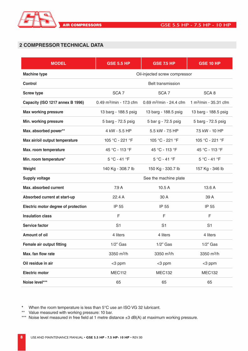
Machine type Oil-injected screw compressor
Control Belt transmission
Screw type SCA 7 SCA 7 SCA 8
Capacity (ISO 1217 annex B 1996) 0.49 m3/min - 17.3 cfm 0.69 m3/min - 24.4 cfm 1 m3/min - 35.31 cfm
Max working pressure 13 barg - 188.5 psig 13 barg - 188.5 psig 13 barg - 188.5 psig
Min. working pressure 5 barg - 72.5 psig 5 bar g - 72.5 psig 5 barg - 72.5 psig
Max. absorbed power** 4 kW - 5.5 HP 5.5 kW - 7.5 HP 7.5 kW - 10 HP
Max air/oil output temperature 105 °C - 221 °F 105 °C - 221 °F 105 °C - 221 °F
Max. room temperature 45 °C - 113 °F 45 °C - 113 °F 45 °C - 113 °F
Min. room temperature* 5 °C - 41 °F 5 °C - 41 °F 5 °C - 41 °F
Weight 140 Kg - 308.7 lb 150 Kg - 330.7 lb 157 Kg - 346 lb
Supply voltage See the machine plate
Max. absorbed current 7.9 A 10.5 A 13.6 A
Absorbed current at start-up 22.4 A 30 A 39 A
Electric motor degree of protection IP 55 IP 55 IP 55
Insulation class F F F
Service factor S1 S1 S1
Amount of oil 4 liters 4 liters 4 liters
Female air output fitting 1/2” Gas 1/2” Gas 1/2” Gas
Max. fan flow rate 3350 m3/h 3350 m3/h 3350 m3/h
Oil residue in air <3 ppm <3 ppm <3 ppm
Electric motor MEC112 MEC132 MEC132
Noise level*** 65 65 65
2 COMPRESSOR TECHNICAL DATA
* When the room temperature is less than 5°C use an ISO VG 32 lubricant.** Value measured with working pressure: 10 bar.*** Noise level measured in free field at 1 metre distance ±3 dB(A) at maximum working pressure.
GSE 5.5 HP - 7.5 HP - 10 HP
9USE AND MAINTENANCE MANUAL • GSE 5.5 HP - 7.5 HP- 10 HP • REV. 00
P L
H
H
P L
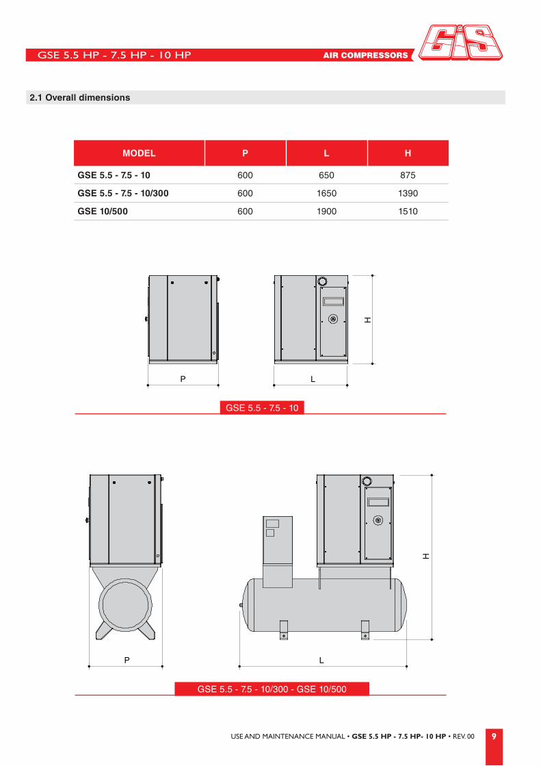
MODEL P L H
GSE 5.5 - 7.5 - 10 600 650 875
GSE 5.5 - 7.5 - 10/300 600 1650 1390
GSE 10/500 600 1900 1510
GSE 5.5 - 7.5 - 10/300 - GSE 10/500
GSE 5.5 - 7.5 - 10
2.1 Overall dimensions

GSE 5.5 HP - 7.5 HP - 10 HP
10 USE AND MAINTENANCE MANUAL • GSE 5.5 HP - 7.5 HP- 10 HP • REV. 00
3 UNPACKING
4 POSITIONING
The compressor must be lifted using a fork-lift truck of an appropriate capacity.• Check that the external packaging is undamaged. • Unpack the machine carefully.• Check that the outside of the machine is undamaged.• Dispose of the packaging according to the environmental laws in force.
The compressor must be handled as shown in the figure.
The room where the compressor is installed must have the requirements laid down in the accident prevention laws in force as well as the following characteristics:
• Low dust percentages. • Appropriate ventilation and a size that ensures, with the machine running, suitable room temperatures (min 5°,
max 45°).

GSE 5.5 HP - 7.5 HP - 10 HP
11USE AND MAINTENANCE MANUAL • GSE 5.5 HP - 7.5 HP- 10 HP • REV. 00
4.1 Positioning the compressor
Make sure that the compressor is placed on a flat surface. The compressor does not require any specific preparation of the supporting surface. Anti vibration devices with relative nuts and washers may be supplied on request.
WARNING• Do not install check valves between the compressor and the tank. • Pipes must not exceed 3 metres in length; otherwise install a fan on the output side (see
figure). • Pipes must have a constant section equal to aerator area. • The condensate must not be dispersed into the atmosphere or into the mains drains. The
drainage pit must be fitted with a valve and a removable container, and must be connected to suitable equipment for separating the water from the oil.
800 mm
800 mm
If the hot air ventilation is inadequate, install fans in the room as high as possible (see figure).

GSE 5.5 HP - 7.5 HP - 10 HP
12 USE AND MAINTENANCE MANUAL • GSE 5.5 HP - 7.5 HP- 10 HP • REV. 00
5 BEFORE START-UP
5.1 Using the compressor
5.2 Lubricating the compressor
When starting the machine for the first time, make sure that:• the supply voltage corresponds to that indicated on the plate;• the size of the main switch mounted on the wall must comply with the
indications in the technical data table;• check for the correct oil level;• the electrical connections must be done with appropriately sized cables
(see Chapter "Connecting the compressor to the electricity supply".
ATTENTIONStrictly follow the SAFETY WARNINGS concerning the use of the machine.For the European market, tanks are built in compliance with EC Directive 87/404/EEC, and compressors are built in compliance with Directive 98/37/EEC.Check your model on the data plate shown on the compressor and at the beginning of this manual.
IMPORTANTBefore carrying out any operations to remove or top up the oil in the compressor, disconnect the power supply and wait for the system to return to normal pressure.Handle lubricants with appropriate protection.
WARNINGNEVER DIRECT THE AIR JET TOWARDS PERSONS OR ANIMALS. DO NOT USE COMPRESSED AIR FOR RESPIRATORY PURPOSES OR IN PRODUCTION PROCESSES IN WHICH THE AIR PRODUCED, UNLESS PREVIOUSLY TREATED AND FILTERED, COMES INTO DIRECT CONTACT WITH FOOD PRODUCTS.
ESSO Exolub 46
SHELL Corena d 46
TOTAL Azolla zs 46
MOBIL Dte oil 25
BP Energol hlp 46
DUCKHAMS Zircon 46
AGIP Dicrea 46
IN THE EVENT OF ANY OTHER USE, THE MANUFACTURER SHALL NOT BE LIABLE FOR ANY RISKS CAUSED.IN THE EVENT OF USE OF THE COMPRESSOR IN A MANNER OTHER THAN THAT AGREED AT THE TIME OF PURCHASE THE MANUFACTURER SHALL NOT BE LIABLE FOR ANY INJURY OR DAMAGE TO PROPERTY OR THE MACHINE ITSELF.
The compressors are designed and constructed solely to produce compressed air.
You are advised to use a lubricant that is compatible with ISO VG 46 oil (mineral base oil) used during testing. The pour point must be at least -8+10°C and the flash point must be above +200°C.
When using incompatible oil, follow the procedure described in chapter "Using the compressor with synthetic base oil”.
The electrical system shall not be used in explosion-proof environments or for inflammable products.
min
max
GSE 5.5 HP - 7.5 HP - 10 HP
13USE AND MAINTENANCE MANUAL • GSE 5.5 HP - 7.5 HP- 10 HP • REV. 00
5.3 Using the compressor with synthetic base oil
• Never mix oils of different types.
• Use VG32 grade oil in cold climates and VG68 in hot climates.
• Before starting the compressor without oil, add approximately 0.1 l lubricant in the screw assembly.
• Add mineral lubricant to the tank through the hole up to the level shown in the viewer. The quantity of oil used should be around 4 l.
• Switch the compressor on, initially switching on and off with brief pauses, for around 10 minutes in a row.
• Then switch off the compressor, discharge the pressure and top up the lubricant tank through the hole up to the level shown in the viewer.
When using synthetic lubricants follow the procedure described below (washing cycle).
• Remove the mineral lubricant from the circuit through the drain cock.
• Add the synthetic lubricant to the tank through the hole up to the required level and replace oil and separator filters.
• Before starting the motor and running the compressor, when switching on for the first time after installation, add approximately 0.1 l lubricant in the screw assembly.
• Start the compressor and leave it to run for about 10 minutes after which leave it to cool. Check the level of the oil once again and top up if necessary.
GSE 5.5 HP - 7.5 HP - 10 HP
14 USE AND MAINTENANCE MANUAL • GSE 5.5 HP - 7.5 HP- 10 HP • REV. 00
5.4 Connecting the compressor to the electricity supply
The electrical connection of the machine to the mains is done by the customer under his own responsibility, using specialized personnel and in compliance with the accident prevention standard EN 60204.
Avoid all electric shock risks. Never use the compressor with a damaged lead or extension lead. Check the leads often. Never use the compressor in dangerous environments where electric shocks are possible.
EARTHINGThe compressor must be earthed during use in order to protect the operator from electric shocks. The connection must be done by a specialized technician or service center. The earth wire of the power cable on the compressor must be connected exclusively to the terminal on the compressor. Before replacing the plug of the power cable, disconnect the earth wire.
EXTENSIONDo not use damaged extension cables. Make sure the extension lead is in good condition. When using an extension lead, make sure that the cable section is suited to the absorbed current on the compressor. Too thin an extension cable can lead to drops in voltage and power losses or may cause the compressor to overheat. The extension cable section must be proportionate to its length, as shown in the following table:
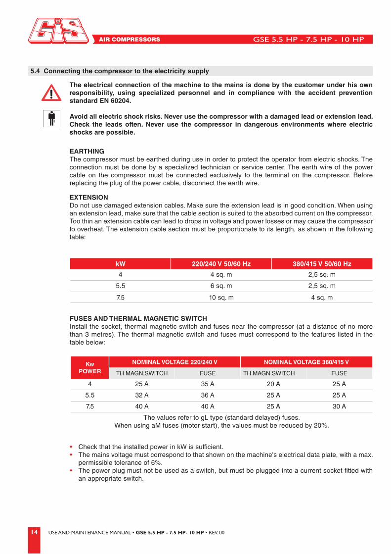
FUSES AND THERMAL MAGNETIC SWITCHInstall the socket, thermal magnetic switch and fuses near the compressor (at a distance of no more than 3 metres). The thermal magnetic switch and fuses must correspond to the features listed in the table below:
kW 220/240 V 50/60 Hz 380/415 V 50/60 Hz
4 4 sq. m 2,5 sq. m
5.5 6 sq. m 2,5 sq. m
7.5 10 sq. m 4 sq. m
Kw POWER
NOMINAL VOLTAGE 220/240 V NOMINAL VOLTAGE 380/415 V
TH.MAGN.SWITCH FUSE TH.MAGN.SWITCH FUSE
4 25 A 35 A 20 A 25 A
5.5 32 A 36 A 25 A 25 A
7.5 40 A 40 A 25 A 30 A
The values refer to gL type (standard delayed) fuses. When using aM fuses (motor start), the values must be reduced by 20%.
• Check that the installed power in kW is sufficient.• The mains voltage must correspond to that shown on the machine's electrical data plate, with a max.
permissible tolerance of 6%.• The power plug must not be used as a switch, but must be plugged into a current socket fitted with
an appropriate switch.
GSE 5.5 HP - 7.5 HP - 10 HP
15USE AND MAINTENANCE MANUAL • GSE 5.5 HP - 7.5 HP- 10 HP • REV. 00
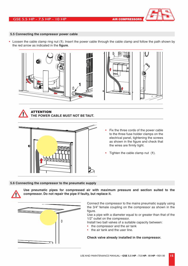
ATTENTIONTHE POWER CABLE MUST NOT BE TAUT.
5.5 Connecting the compressor power cable
Kw POWER
NOMINAL VOLTAGE 220/240 V NOMINAL VOLTAGE 380/415 V
TH.MAGN.SWITCH FUSE TH.MAGN.SWITCH FUSE
4 25 A 35 A 20 A 25 A
5.5 32 A 36 A 25 A 25 A
7.5 40 A 40 A 25 A 30 A
The values refer to gL type (standard delayed) fuses. When using aM fuses (motor start), the values must be reduced by 20%.
• Loosen the cable clamp ring nut (1). Insert the power cable through the cable clamp and follow the path shown by the red arrow as indicated in the figure.
• Fix the three cords of the power cable to the three fuse holder clamps on the electrical panel, tightening the screws as shown in the figure and check that the wires are firmly tight.
• Tighten the cable clamp nut (1).
1
5.6 Connecting the compressor to the pneumatic supply
Use pneumatic pipes for compressed air with maximum pressure and section suited to the compressor. Do not repair the pipe if faulty, but replace it.
Connect the compressor to the mains pneumatic supply using the 3/4” female coupling on the compressor as shown in the figure.Use a pipe with a diameter equal to or greater than that of the 1/2” outlet on the compressor. Install two ball valves of a suitable capacity between:• the compressor and the air tank• the air tank and the user line.
Check valve already installed in the compressor.

GSE 5.5 HP - 7.5 HP - 10 HP
16 USE AND MAINTENANCE MANUAL • GSE 5.5 HP - 7.5 HP- 10 HP • REV. 00
6 FIRST START-UP
The first start-up of the compressor (operational testing) must be done exclusively by a specialized technician.Connect the compressor following the instructions in this manual, and then contact the dealer to validate the technical warranty (see notes in the sales clauses).
Having followed all the assembly instructions illustrated in chapter 6, proceed to prepare the compressor for first start-up.
Every time the compressor is switched on, the control panel checks the power line phases to ensure the correct rotation of the screw assembly. On first start-up, switch on the voltage and press the START button.
CAUTIONThe rotation of the screw assembly in the opposite direction to that indicated by the relief arrow on the body (see figure) may damage the screw assembly.WARNINGIn case of replacing the electric motor, when starting up for the first time you must visually check the direction of rotation of the screw assembly.WARNINGIt is indispensable to strictly follow the SAFETY WARNINGS concerning the use of the machine.
• If the power line phases are correctly positioned, the screw assembly rotates as shown by the arrow in the figure.
• If the power line phases are positioned incorrectly, the control panel will indicate a machine block alarm (see in the specific technical file “Control Panel”). Consequently, change the connections of the two line power phases and start the compressor again.
GSE 5.5 HP - 7.5 HP - 10 HP
17USE AND MAINTENANCE MANUAL • GSE 5.5 HP - 7.5 HP- 10 HP • REV. 00
CAUTIONThe rotation of the screw assembly in the opposite direction to that indicated by the relief arrow on the body (see figure) may damage the screw assembly.WARNINGIn case of replacing the electric motor, when starting up for the first time you must visually check the direction of rotation of the screw assembly.WARNINGIt is indispensable to strictly follow the SAFETY WARNINGS concerning the use of the machine.
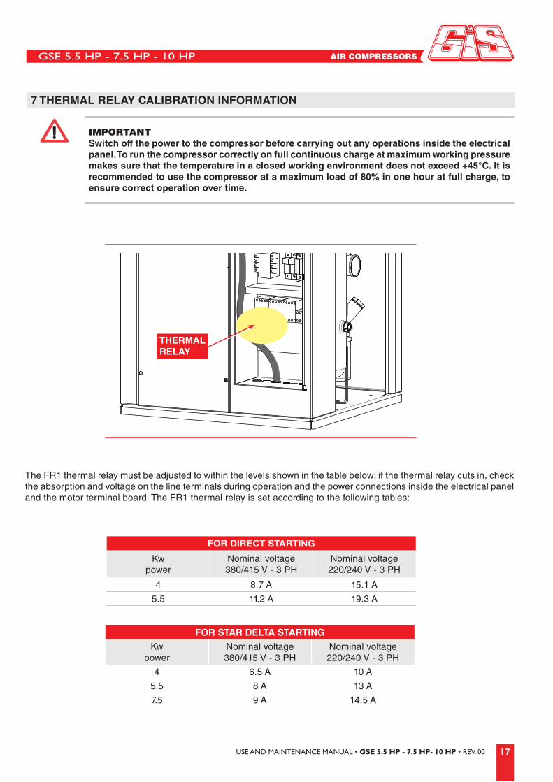
7 THERMAL RELAY CALIBRATION INFORMATION
IMPORTANTSwitch off the power to the compressor before carrying out any operations inside the electrical panel. To run the compressor correctly on full continuous charge at maximum working pressure makes sure that the temperature in a closed working environment does not exceed +45°C. It is recommended to use the compressor at a maximum load of 80% in one hour at full charge, to ensure correct operation over time.
The FR1 thermal relay must be adjusted to within the levels shown in the table below; if the thermal relay cuts in, check the absorption and voltage on the line terminals during operation and the power connections inside the electrical panel and the motor terminal board. The FR1 thermal relay is set according to the following tables:
FOR DIRECT STARTING
Kw power
Nominal voltage 380/415 V - 3 PH
Nominal voltage 220/240 V - 3 PH
4 8.7 A 15.1 A
5.5 11.2 A 19.3 A
FOR STAR DELTA STARTING
Kw power
Nominal voltage 380/415 V - 3 PH
Nominal voltage 220/240 V - 3 PH
4 6.5 A 10 A
5.5 8 A 13 A
7.5 9 A 14.5 A
THERMAL RELAY

GSE 5.5 HP - 7.5 HP - 10 HP
18 USE AND MAINTENANCE MANUAL • GSE 5.5 HP - 7.5 HP- 10 HP • REV. 00
8 ELECTRO-PNEUMATIC CIRCUIT DIAGRAM AND COMPONENT DESCRIPTION
AIR
AIR TANK PRESSURE
SUCTION
M3
M3AIR-OIL
OIL
OIL DRAINOIL INLET
IMPULSE LINEELECTRICITY LINE
1
2
3
412
13
14
15
18
19
1716
20
21
5
6
7
8 9
10 11
PART LIST
1 Suction valve 14 Suction filter
2 Screw compressor 15 Oil filter
3 3/2 solenoid valve 16 Cooling electro-fan
4 Safety valve 17 Suction pre-filter panel
5 Oil radiator 18 Transmission belt
6 Air radiator 19 Electric motor
7 Min. pressure valve 20 Oil level
8 ON button 21 Oil drain
9 Pressure switch
10 Oil return from separator
11 De-oiling filter
12 Air/oil delivery pipe from screw assembly
13 Air/oil separator tank
GSE 5.5 HP - 7.5 HP - 10 HP
19USE AND MAINTENANCE MANUAL • GSE 5.5 HP - 7.5 HP- 10 HP • REV. 00
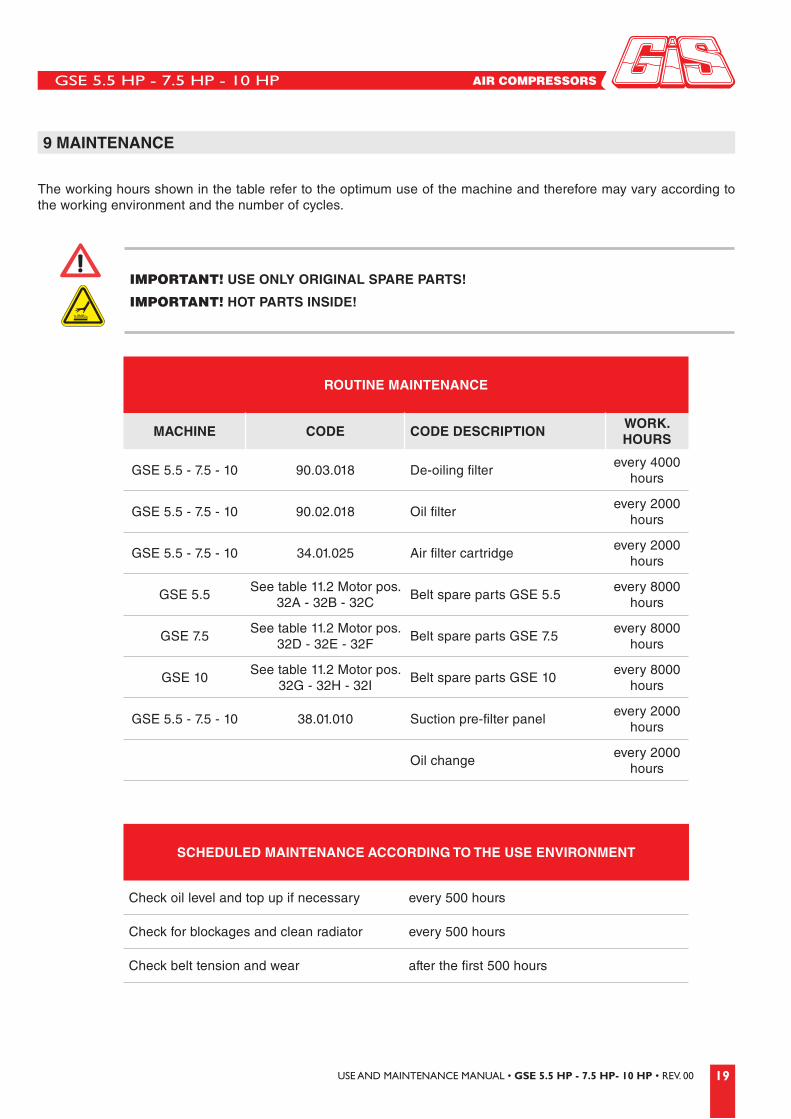
IMPORTANT! USE ONLY ORIGINAL SPARE PARTS!
IMPORTANT! HOT PARTS INSIDE!
ROUTINE MAINTENANCE
MACHINE CODE CODE DESCRIPTIONWORK. HOURS
GSE 5.5 - 7.5 - 10 90.03.018 De-oiling filterevery 4000
hours
GSE 5.5 - 7.5 - 10 90.02.018 Oil filterevery 2000
hours
GSE 5.5 - 7.5 - 10 34.01.025 Air filter cartridgeevery 2000
hours
GSE 5.5See table 11.2 Motor pos.
32A - 32B - 32CBelt spare parts GSE 5.5
every 8000 hours
GSE 7.5See table 11.2 Motor pos.
32D - 32E - 32FBelt spare parts GSE 7.5
every 8000 hours
GSE 10See table 11.2 Motor pos.
32G - 32H - 32IBelt spare parts GSE 10
every 8000 hours
GSE 5.5 - 7.5 - 10 38.01.010 Suction pre-filter panelevery 2000
hours
Oil changeevery 2000
hours
SCHEDULED MAINTENANCE ACCORDING TO THE USE ENVIRONMENT
Check oil level and top up if necessary every 500 hours
Check for blockages and clean radiator every 500 hours
Check belt tension and wear after the first 500 hours
9 MAINTENANCE
The working hours shown in the table refer to the optimum use of the machine and therefore may vary according to the working environment and the number of cycles.

GSE 5.5 HP - 7.5 HP - 10 HP
20 USE AND MAINTENANCE MANUAL • GSE 5.5 HP - 7.5 HP- 10 HP • REV. 00
PROCEDURE FOR TENSIONING THE BELT
1 Remove the front panel.
2 Unscrew the two locking nuts A on the transmission plate tie rods.
3 Unscrew the four locking nuts B on the transmission plate.
BA
WARNINGEXCESSIVE BELT TENSION WILL REDUCE THE LIFE OF THE SCREW BEARINGS. MAKE SURE THAT THE TRANSMISSION IS PROTECTED WHEN THE MACHINE IS RUNNING IN ORDER TO PREVENT INJURY.
Make sure that the pulleys mounted on the shafts are correctly aligned and that the belts have the correct tension.For belt transmission, you are advised to use the “POLY V” model. The recommended tension values are given in the table below.
MODELINITIAL TENSIONING WITH NEW BELT
[N]TENSION OF BROKEN IN BELT OR
RE-TENSIONING [N]
GSE 5.5 275 215
GSE 7.5 400 300
GSE 10 410 320
9.1 Tensioning the belts

GSE 5.5 HP - 7.5 HP - 10 HP
21USE AND MAINTENANCE MANUAL • GSE 5.5 HP - 7.5 HP- 10 HP • REV. 00
4Screw the two tie rods C taking care to tension them so that the tensioning plate is as flat as possible.
5 Set the tension according to the following table and once the belt is taut take care to:- tighten the four plate fixing screws B;- tighten the locking nuts A of the two tie rods C;- reassemble the front panel and fix with the 4 screws;- check the actual belt tension.
C
9.2 Suction pre-filter maintenance and replacement
1 Slide the pre-filter out from the guides (rear mobile part) and clean it carefully with a jet of air.
2 Reassemble the clean pre-filter on the guides taking care to position it so that it covers the whole suction surface of the compressor.
GSE 5.5 HP - 7.5 HP - 10 HP
22 USE AND MAINTENANCE MANUAL • GSE 5.5 HP - 7.5 HP- 10 HP • REV. 00
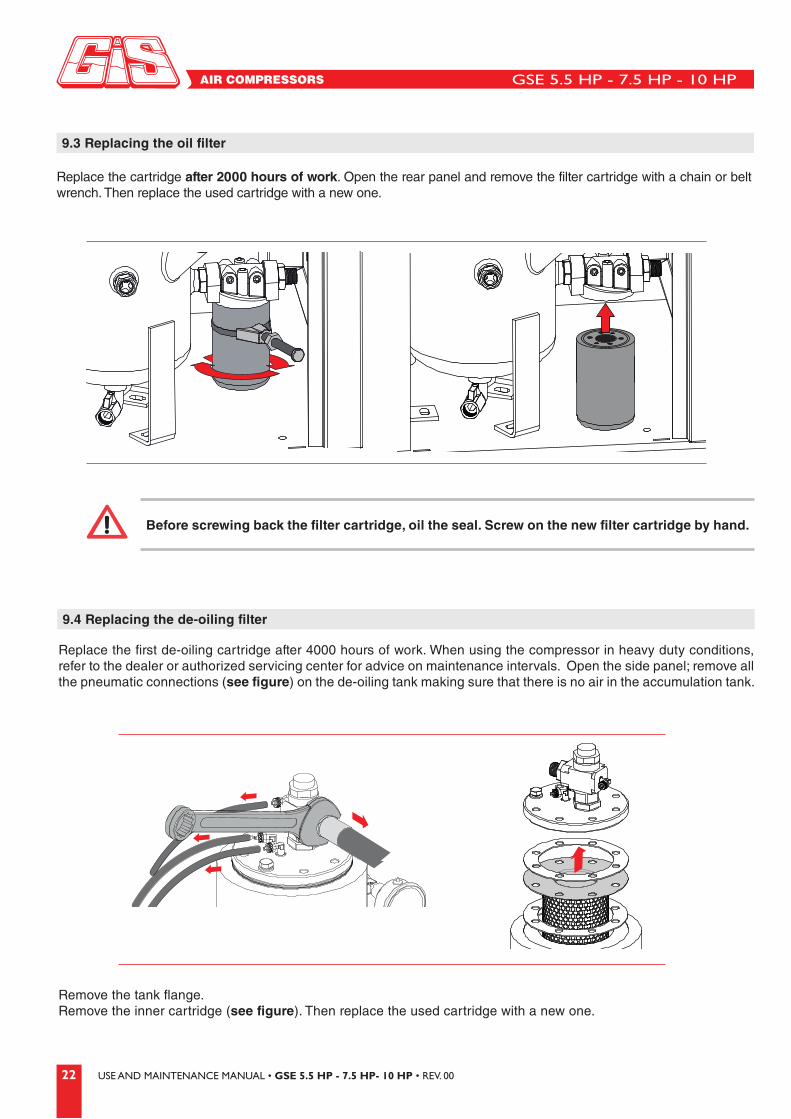
9.3 Replacing the oil filter
9.4 Replacing the de-oiling filter
Replace the cartridge after 2000 hours of work. Open the rear panel and remove the filter cartridge with a chain or belt wrench. Then replace the used cartridge with a new one.
Replace the first de-oiling cartridge after 4000 hours of work. When using the compressor in heavy duty conditions, refer to the dealer or authorized servicing center for advice on maintenance intervals. Open the side panel; remove all the pneumatic connections (see figure) on the de-oiling tank making sure that there is no air in the accumulation tank.
Before screwing back the filter cartridge, oil the seal. Screw on the new filter cartridge by hand.
Remove the tank flange.Remove the inner cartridge (see figure). Then replace the used cartridge with a new one.
GSE 5.5 HP - 7.5 HP - 10 HP
23USE AND MAINTENANCE MANUAL • GSE 5.5 HP - 7.5 HP- 10 HP • REV. 00
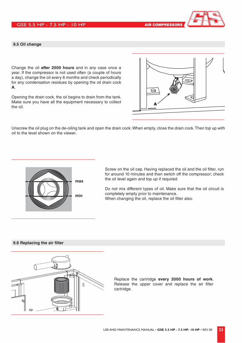
9.3 Replacing the oil filter 9.5 Oil change
9.6 Replacing the air filter
Change the oil after 2000 hours and in any case once a year. If the compressor is not used often (a couple of hours a day), change the oil every 6 months and check periodically for any condensation residues by opening the oil drain cock A.
Opening the drain cock, the oil begins to drain from the tank. Make sure you have all the equipment necessary to collect the oil.
Replace the cartridge every 2000 hours of work. Release the upper cover and replace the air filter cartridge.
Unscrew the oil plug on the de-oiling tank and open the drain cock. When empty, close the drain cock. Then top up with oil to the level shown on the viewer.
Screw on the oil cap. Having replaced the oil and the oil filter, run for around 10 minutes and then switch off the compressor; check the oil level again and top up if required.
Do not mix different types of oil. Make sure that the oil circuit is completely empty prior to maintenance. When changing the oil, replace the oil filter also.
A
min
max

GSE 5.5 HP - 7.5 HP - 10 HP
24 USE AND MAINTENANCE MANUAL • GSE 5.5 HP - 7.5 HP- 10 HP • REV. 00
10 COMPRESSOR MAINTENANCE CHECK SHEET
TABLE OF PERFORMED JOBS
Hours ofoperation
Pre-filter panel
Air filter cartridge
Oil filter cartridge
Separator cartridge
Oil Belt Date Signature
Cle
anin
g
Rep
lace
men
t
Cle
anin
g
Rep
lace
men
t
Rep
lace
men
t
Pre
ssur
e di
ffere
nce
Pre
ssur
e di
ffere
nce
Rep
lace
men
t
Con
trol
Top
up
Cha
nge
Con
trol
Tens
ioni
ng
Rep
lace
men
t

GSE 5.5 HP - 7.5 HP - 10 HP
25USE AND MAINTENANCE MANUAL • GSE 5.5 HP - 7.5 HP- 10 HP • REV. 00
11 SPARE PARTS
GSE 5.5 HP - 7.5 HP - 10 HP
26 USE AND MAINTENANCE MANUAL • GSE 5.5 HP - 7.5 HP- 10 HP • REV. 00
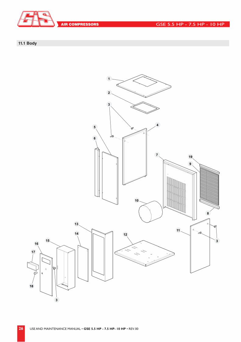
11.1 Body
1
2
3
4
6
10
7
8
9
1112
13
14
15
3
16
17
18
5
3
19

GSE 5.5 HP - 7.5 HP - 10 HP
27USE AND MAINTENANCE MANUAL • GSE 5.5 HP - 7.5 HP- 10 HP • REV. 00
N° CODE DESCRIPTION
1 50.08.044 Upper cover
2 50.08.103 Radiator frame
3 07.01.001 Lock
4 50.08.045 Left panel
5 50.08.052 Front panel
6 50.08.051 Upright
7 50.08.042 Rear panel
8 50.08.033 Lower pre-filter guide
9 38.01.010 Pre-filtering frame 400 x 500
10A 50.08.043 Electric motor fairing (10 HP)
10B 50.08.214 Electric motor fairing (5.5 HP / 7.5 HP)
11 50.08.053 RH panel
12 50.08.038 Base
13 50.08.049 "L" electrical panel holder panel
14 50.08.046 Electrical panel holder panel
15 50.08.047 Electrical panel box
16 50.08.048 Door
17 90.40.011 Electronic diagram Logika 8
18 90.40.019 Emergency mushroom push - button
19 50.08.032 Upper pre-filter guide
GSE 5.5 HP - 7.5 HP - 10 HP
28 USE AND MAINTENANCE MANUAL • GSE 5.5 HP - 7.5 HP- 10 HP • REV. 00
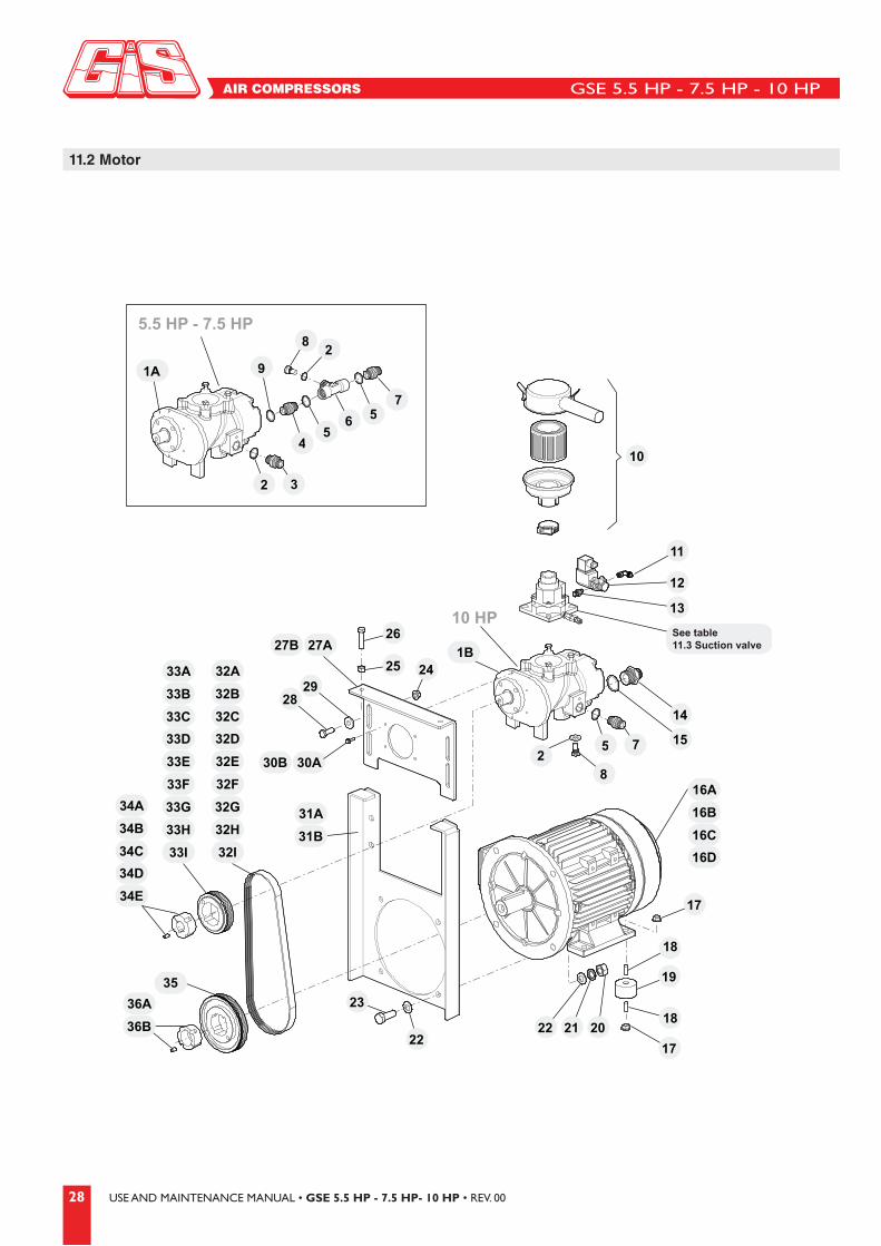
11.2 Motor
14
15
8
24
28
23
2222 21 20
19
17
29
25
26
11
10
12
13
565
4
7
28
91A
5.5 HP - 7.5 HP
10 HP
32
See table11.3 Suction valve
1B27A
30A75
230B
34A
34B31A
31B
36A
36B
35
34C
34D
34E
33A
33B
33C
33D
16A
16B
16C
16D
33E
33F
33G
33H
33I
32A
32B
32C
32D
32E
32F
32G
32H
32I
27B
18
18
17

GSE 5.5 HP - 7.5 HP - 10 HP
29USE AND MAINTENANCE MANUAL • GSE 5.5 HP - 7.5 HP- 10 HP • REV. 00
1A 03.04.001 Screw assembly SCA7 (5.5 HP / 7.5 HP)
1B 03.04.002 Screw assembly SCA8 (10 HP)
2 42.03.004 Copper washer 1/4" G
3 14.50.012 Nipple 1/4" x 3/8" G
4 14.50.010 Nipple 3/4" x 1/2" G cylindrical
5 42.03.001 Washer 1/2" G
6 12.03.014 T- coupling 1/2" G - 1/4" G - 1/2" G
7 14.50.001 Nipple 1/2" G cylindrical
8 12.01.031 Sump 1/4" G for temperature probe
9 42.03.002 Copper washer 3/4" G
10 34.01.024 Complete filter kit SIL 39
11 12.02.035 Push-on fitting 1/4" G x 6
12 90.40.036 Solenoid valve 1/4" G F-F N0 24V AC
13 14.01.002 Nipple 1/4" G
14 14.50.013 Reduction nipple 1" 3/4 G
15 42.03.003 Copper washer 1" G
16A 02.05.001 Electric motor B3/B5 HP 5.5 MEC 112 220/400V/50HZ
16B 02.05.002 Electric motor B3/B5 HP 7.5 MEC 112 220/400V/50HZ
16C 02.05.013 Electric motor B3/B5 HP 10 MEC 132 220/400V/60HZ
16D 02.05.003 Electric motor B3/B5 HP 10 MEC 132 400/700V/50HZ
17 41.05.003 Knurled collar nut M10
18 40.10.002 Grub screw M10 x 35
19 30.01.011 Anti-vibration pad
20 41.02.004 Medium size nut M14
21 42.02.004 Grover washer Ø 14
22 42.01.005 Washer Ø 14
23 40.01.021 Hex.head screw M14 x 40
24 41.05.003 Knurled collar nut M10
25 41.01.003 Nut M10 high
26 40.01.012 Hex.head screw TE M10 x 40
27A 50.08.040 Upper screw support plate (5.5 HP / 7.5 HP)
27B 50.08.050 Upper screw support plate (10 HP)
28 40.01.011 Hex.head screw M10 x 30
29 42.01.011 Washer Ø 10
30A 40.05.015 Screw TS PEI M8 x 16 (5.5 HP / 7.5 HP)
30B 40.01.022 Screw TBEI M6 X 35 (10 HP)
31A 50.08.039 Lower screw support plate (5.5 HP / 7.5 HP)
31B 50.08.065 Lower screw support plate (10 HP)
32A 11.06.030 Belt J8 350 (5.5 HP - 8 bar)
32B 11.06.001 Belt J8 360 (5.5 HP - 10 bar)
32C 11.06.002 Belt J8 380 (5.5 HP - 13 bar)
32D 11.06.036 Belt J8 330 (7.5 HP - 8 bar)
32E 11.06.035 Belt J8 340 (7.5 HP - 10 bar)
32F 11.06.030 Belt J8 350 (7.5 HP - 13 bar)
32G 11.06.002 Belt J8 380 (10 HP - 8 bar)
32H 11.06.002 Belt J8 380 (10 HP - 10 bar)
32I 11.06.010 Belt J8 390 (10 HP - 13 bar)
33A 09.05.001 Screw pulley J8 Ø 100 (5.5 HP - 8 bar)
33B 09.05.003 Screw pulley J8 Ø 118 (5.5 HP - 10 bar)
33C 09.05.005 Screw pulley J8 Ø 132 (5.5 HP - 13 bar)
33D 09.05.045 Screw pulley J8 Ø 75 (5.5 HP - 8 bar)
33E 09.05.046 Screw pulley J8 Ø 85 (7.5 HP - 10 bar)
33F 09.05.009 Screw pulley J8 Ø 95 (7.5 HP - 13 bar)
33G 09.05.001 Screw pulley J8 Ø 100 (10 HP - 8 bar)
33H 09.05.003 Screw pulley J8 Ø 118 (10 HP - 10 bar)
33I 09.05.004 Screw pulley J8 Ø 140 (10 HP - 13 bar)
34A 09.05.103 Screw pulley sleeve Ø 19 16.10 (5.5 HP - 8/10/13 bar)
34B 09.05.105 Screw pulley sleeve Ø 19 11.08 (7.5 HP - 8 bar)
34C 09.05.114 Screw pulley sleeve Ø 19 13.10 (7.5 HP - 10 bar)
34D 09.05.103 Screw pulley sleeve Ø 19 16.10 (7.5 HP - 13 bar)
34E 09.05.101 Screw pulley sleeve Ø 25 16.10 (10 HP - 8/10/13 bar)
35 09.05.042 Poli-v motor pulley J8 Ø 160 (5.5 / 7.5 / 10 HP)
36A 09.05.122 Motor pulley sleeve Ø 28 20.12 (5.5 HP / 7.5 HP)
36B 09.05.102 Motor pulley sleeve Ø 38 20.12 (10 HP)
N° CODE DESCRIPTION N° CODE DESCRIPTION

GSE 5.5 HP - 7.5 HP - 10 HP
30 USE AND MAINTENANCE MANUAL • GSE 5.5 HP - 7.5 HP- 10 HP • REV. 00
11.3 Suction valve
3A
5.5 HP - 7.5 HP
22
21
20
19
15 16 17
2
5
7
8
12
14
1A
9A
10A
11A
18A
13A
6A
1B
4A
3B22
21
20
19
15 16 17
2
5
7
8
12
14
9B
10B
11B
18B
13B
6B
4B
10 HP
5.5 HP - 7.5 HP 10 HP

GSE 5.5 HP - 7.5 HP - 10 HP
31USE AND MAINTENANCE MANUAL • GSE 5.5 HP - 7.5 HP- 10 HP • REV. 00
N° CODE DESCRIPTION
1A 90.25.013 Complete suction valve S8 (5.5 HP / 7.5 HP)
1B 90.25.011 Complete suction valve S11 (10 HP)
2 40.04.008 Hex.screw M5
3A 50.13.035 Suction valve upper casing S8 (5.5 HP / 7.5 HP)
3B 50.13.008 Suction valve upper casing S11 (10 HP)
4A 50.13.039 Screw cover cap S8 (5.5 HP / 7.5 HP)
4B 50.13.007 Screw cover cap S11 (10 HP)
5 50.13.006 Spring
6A 90.25.126 O-ring 032 NBR 47,35 x 1,78 suction valve S8 (5.5 HP / 7.5 HP)
6B 90.25.103 O-ring 036 NBR 60,5 x 1,78 suction valve S11 (10 HP)
7 40.04.006 Screw TBEI M8 x 25
8 42.01.008 Washer Ø 8 x 24 x 2
9A 50.13.036 Suction valve base S8 (5.5 HP / 7.5 HP)
9B 50.13.005 Suction valve base S11 (10 HP)
10A 50.13.038 Suction valve cap S8 (5.5 HP / 7.5 HP)
10B 50.13.003 Suction valve cap S11 (10 HP)
11A 90.25.127 O-ring 138 NBR 53,5 x 2,6 suction valve S8 (5.5 HP / 7.5 HP)
11B 90.25.102 O-ring 041 NBR 75,92 x 1,78 suction valve S11 (10 HP)
12 50.13.019 Spring
13A 50.13.037 Fork S8 (5.5 HP / 7.5 HP)
13B 50.13.002 Fork S11 (10 HP)
14 40.03.022 Socket head screw M4
15 14.01.011 Nipple 1/8" G
16 90.40.008 One-way oil recovery valve 1/8" G FF
17 12.01.033 Coupling 1/8" G x 6
18A 90.25.125 O-ring 011 NBR 7,65 x 1,78 suction valve S8 (5.5 HP / 7.5 HP)
18B 90.25.104 O-ring 012 NBR 9,25 x 1,78 suction valve S11 (10 HP)
19 50.13.009 Ball support brass valve
20 41.03.017 Hexagonal nut
21 50.13.010 Regulator
22 14.05.015 Grub screw 1/8" G

GSE 5.5 HP - 7.5 HP - 10 HP
32 USE AND MAINTENANCE MANUAL • GSE 5.5 HP - 7.5 HP- 10 HP • REV. 00
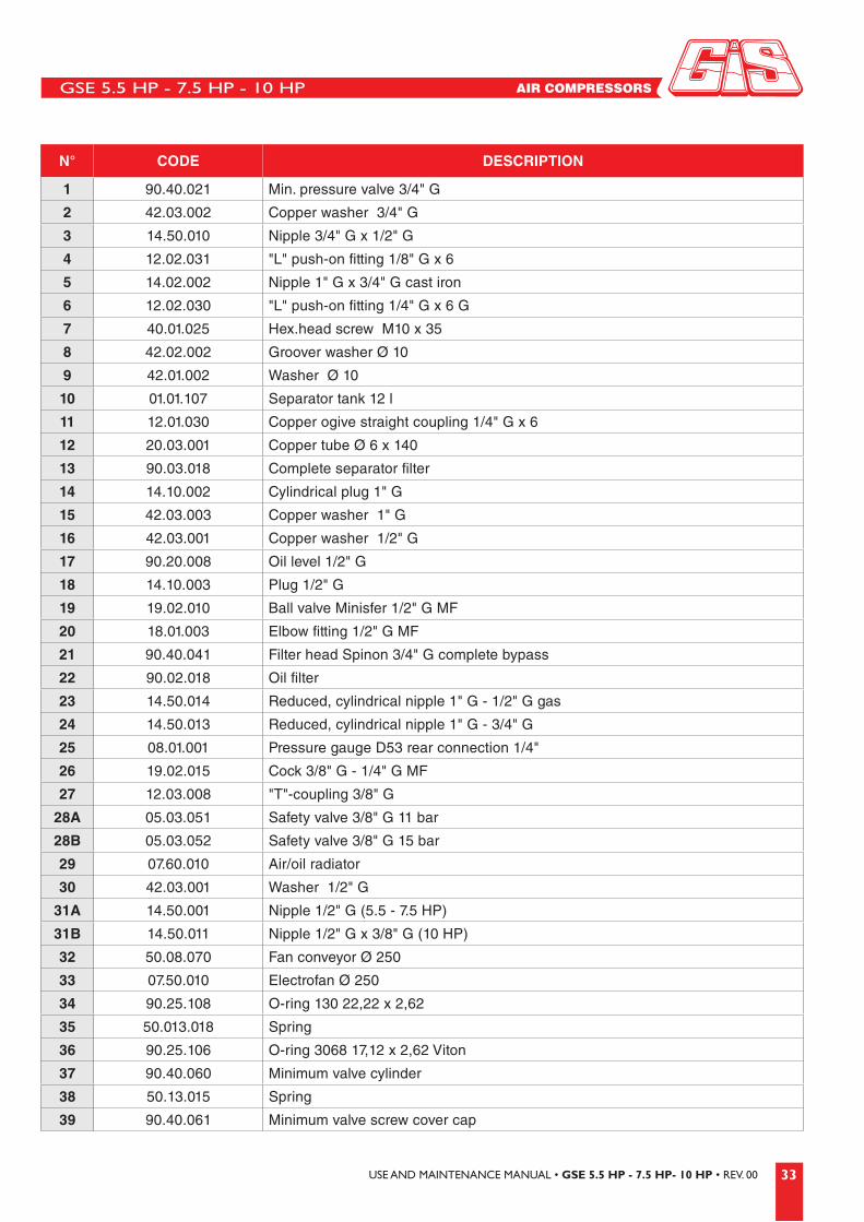
11.4 Fan – Tank Assembly
10 HP
34
35
36
37
38
391
4
5
6
10
11
12
13
67
8
9
23
10
14
15
16
17
161820
2
2
22
3
2
21
23
24
25
26
27
15
15
3
19
29
30
32
33
30
31A31B
28B28A
GSE 5.5 HP - 7.5 HP - 10 HP
33USE AND MAINTENANCE MANUAL • GSE 5.5 HP - 7.5 HP- 10 HP • REV. 00
N° CODE DESCRIPTION
1 90.40.021 Min. pressure valve 3/4" G
2 42.03.002 Copper washer 3/4" G
3 14.50.010 Nipple 3/4" G x 1/2" G
4 12.02.031 "L" push-on fitting 1/8" G x 6
5 14.02.002 Nipple 1" G x 3/4" G cast iron
6 12.02.030 "L" push-on fitting 1/4" G x 6 G
7 40.01.025 Hex.head screw M10 x 35
8 42.02.002 Groover washer Ø 10
9 42.01.002 Washer Ø 10
10 01.01.107 Separator tank 12 l
11 12.01.030 Copper ogive straight coupling 1/4" G x 6
12 20.03.001 Copper tube Ø 6 x 140
13 90.03.018 Complete separator filter
14 14.10.002 Cylindrical plug 1" G
15 42.03.003 Copper washer 1" G
16 42.03.001 Copper washer 1/2" G
17 90.20.008 Oil level 1/2" G
18 14.10.003 Plug 1/2" G
19 19.02.010 Ball valve Minisfer 1/2" G MF
20 18.01.003 Elbow fitting 1/2" G MF
21 90.40.041 Filter head Spinon 3/4" G complete bypass
22 90.02.018 Oil filter
23 14.50.014 Reduced, cylindrical nipple 1" G - 1/2" G gas
24 14.50.013 Reduced, cylindrical nipple 1" G - 3/4" G
25 08.01.001 Pressure gauge D53 rear connection 1/4"
26 19.02.015 Cock 3/8" G - 1/4" G MF
27 12.03.008 "T"-coupling 3/8" G
28A 05.03.051 Safety valve 3/8" G 11 bar
28B 05.03.052 Safety valve 3/8" G 15 bar
29 07.60.010 Air/oil radiator
30 42.03.001 Washer 1/2" G
31A 14.50.001 Nipple 1/2" G (5.5 - 7.5 HP)
31B 14.50.011 Nipple 1/2" G x 3/8" G (10 HP)
32 50.08.070 Fan conveyor Ø 250
33 07.50.010 Electrofan Ø 250
34 90.25.108 O-ring 130 22,22 x 2,62
35 50.013.018 Spring
36 90.25.106 O-ring 3068 17,12 x 2,62 Viton
37 90.40.060 Minimum valve cylinder
38 50.13.015 Spring
39 90.40.061 Minimum valve screw cover cap

GSE 5.5 HP - 7.5 HP - 10 HP
34 USE AND MAINTENANCE MANUAL • GSE 5.5 HP - 7.5 HP- 10 HP • REV. 00
11.5 Connections
2A 2B
1
3A 3B 4A 4B

GSE 5.5 HP - 7.5 HP - 10 HP
35USE AND MAINTENANCE MANUAL • GSE 5.5 HP - 7.5 HP- 10 HP • REV. 00
N° CODE DESCRIPTION
1 20.05.013 Pipe SAE 100 1/2"G x 260 straight/bend 90°
2A 20.05.014 Pipe AP Equator 3/8"G x 410 straight/bend 90° (5.5 - 7.5 HP)
2B 20.05.010 Pipe AP Equator 1/2"G x 410 straight/bend 90° (10 HP)
3A 20.05.015 Pipe AP Equator 3/8"G x 510 straight/bend 90° (5.5 - 7.5 HP)
3B 20.05.011 Pipe AP Equator 1/2"G x 490 straight/bend 90° (10 HP)
4A 20.05.016 Pipe AP Equator 1/2"G x 460 straight/bend 90° (5.5 - 7.5 HP)
4B 20.05.012 Pipe AP Equator 3/4"G x 460 straight/bend 90° (10 HP)
GSE 5.5 HP - 7.5 HP - 10 HP
36 USE AND MAINTENANCE MANUAL • GSE 5.5 HP - 7.5 HP- 10 HP • REV. 00
GSE 5.5 HP - 7.5 HP - 10 HP
37USE AND MAINTENANCE MANUAL • GSE 5.5 HP - 7.5 HP- 10 HP • REV. 00
12 ELECTRIC DIAGRAMS
GSE 5.5 HP - 7.5 HP - 10 HP
38 USE AND MAINTENANCE MANUAL • GSE 5.5 HP - 7.5 HP- 10 HP • REV. 00
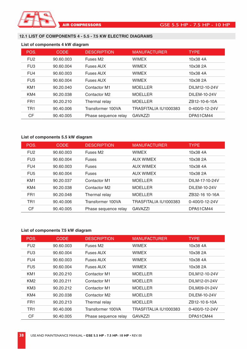
POS. CODE DESCRIPTION MANUFACTURER TYPE
FU2 90.60.003 Fuses M2 WIMEX 10x38 4A
FU3 90.60.004 Fuses AUX WIMEX 10x38 2A
FU4 90.60.003 Fuses AUX WIMEX 10x38 4A
FU5 90.60.004 Fuses AUX WIMEX 10x38 2A
KM1 90.20.040 Contactor M1 MOELLER DILM12-10-24V
KM4 90.20.038 Contactor M2 MOELLER DILEM-10-24V
FR1 90.20.210 Thermal relay MOELLER ZB12-10-6-10A
TR1 90.40.006 Transformer 100VA TRASFITALIA IU1000383 0-400/0-12-24V
CF 90.40.005 Phase sequence relay GAVAZZI DPA51CM44
POS. CODE DESCRIPTION MANUFACTURER TYPE
FU2 90.60.003 Fuses M2 WIMEX 10x38 4A
FU3 90.60.004 Fuses AUX WIMEX 10x38 2A
FU4 90.60.003 Fuses AUX WIMEX 10x38 4A
FU5 90.60.004 Fuses AUX WIMEX 10x38 2A
KM1 90.20.037 Contactor M1 MOELLER DILM-17-10-24V
KM4 90.20.038 Contactor M2 MOELLER DILEM-10-24V
FR1 90.20.048 Thermal relay MOELLER ZB32-16 10-16A
TR1 90.40.006 Transformer 100VA TRASFITALIA IU1000383 0-400/0-12-24V
CF 90.40.005 Phase sequence relay GAVAZZI DPA51CM44
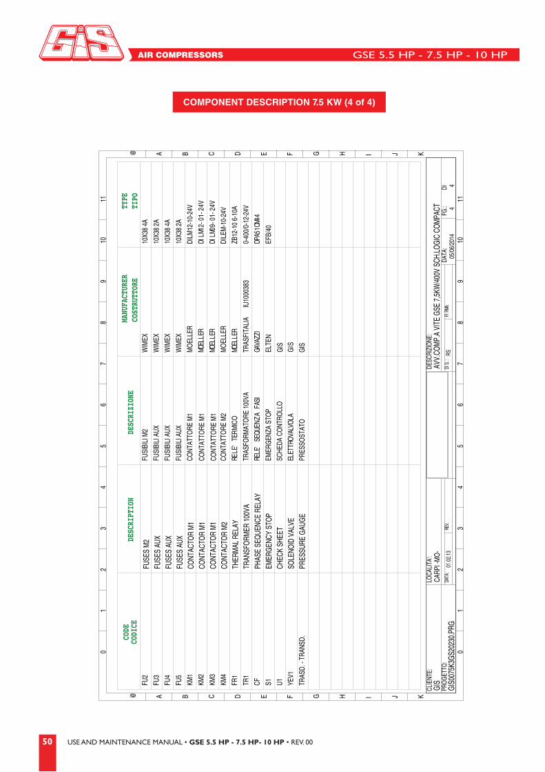
POS. CODE DESCRIPTION MANUFACTURER TYPE
FU2 90.60.003 Fuses M2 WIMEX 10x38 4A
FU3 90.60.004 Fuses AUX WIMEX 10x38 2A
FU4 90.60.003 Fuses AUX WIMEX 10x38 4A
FU5 90.60.004 Fuses AUX WIMEX 10x38 2A
KM1 90.20.210 Contactor M1 MOELLER DILM12-10-24V
KM2 90.20.211 Contactor M1 MOELLER DILM12-01-24V
KM3 90.20.212 Contactor M1 MOELLER DILM09-01-24V
KM4 90.20.038 Contactor M2 MOELLER DILEM-10-24V
FR1 90.20.213 Thermal relay MOELLER ZB12-10 6-10A
TR1 90.40.006 Transformer 100VA TRASFITALIA IU1000383 0-400/0-12-24V
CF 90.40.005 Phase sequence relay GAVAZZI DPA51CM44
List of components 5.5 kW diagram
List of components 7.5 kW diagram
12.1 LIST OF COMPONENTS 4 - 5.5 - 7.5 KW ELECTRIC DIAGRAMS
List of components 4 kW diagram
GSE 5.5 HP - 7.5 HP - 10 HP
39USE AND MAINTENANCE MANUAL • GSE 5.5 HP - 7.5 HP- 10 HP • REV. 00
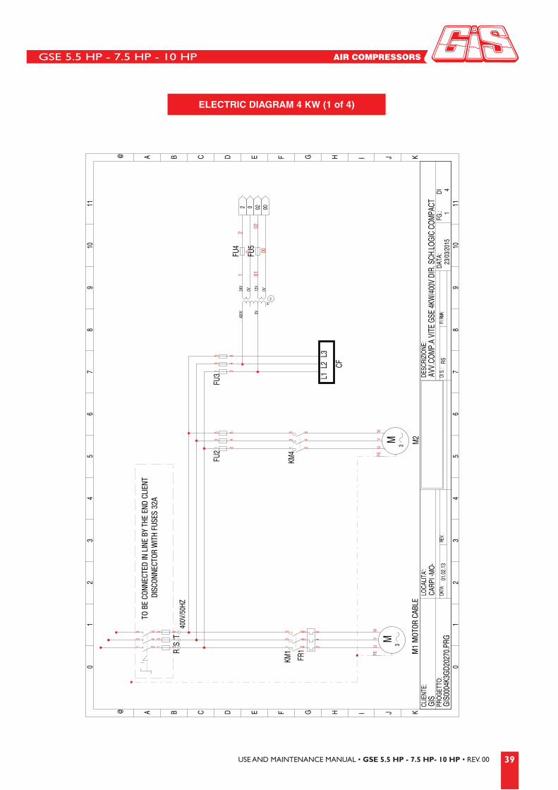
ELECTRIC DIAGRAM 4 KW (1 of 4)
TO B
E CO
NNEC
TED
IN L
INE
BY T
HE E
ND C
LIEN
T DI
SCON
NECT
OR W
ITH
FUSE
S 32
A
M1
MOT
OR C
ABLE

GSE 5.5 HP - 7.5 HP - 10 HP
40 USE AND MAINTENANCE MANUAL • GSE 5.5 HP - 7.5 HP- 10 HP • REV. 00
PROB
E TRAN
SD.
PRESS.GAUGE CABLE
ELECTRIC DIAGRAM 4 KW (2 of 4)

GSE 5.5 HP - 7.5 HP - 10 HP
41USE AND MAINTENANCE MANUAL • GSE 5.5 HP - 7.5 HP- 10 HP • REV. 00
01
23
45
67
89
1011
01
23
45
67
89
1011
@ A B C D E F G H I J K
@ A B C D E F G H I J K
GIS
CARPI -MO-
PROG
ETTO
:DA
TA:
DATA:
REV.
01.02.13
FG.:
DI3
DESC
RIZI
ONE:
AVV.COMP.A VITE GSE 4KW/400V DIR. SCH.LOGIC COMPACT
DIS.:
FIRMA:
RSGIS0004K3GD20270.PRG
04/0
2/13
4
CLIE
NTE:
LOCA
LITA
':
FU2
FU3 FU
4FU5
TR1
KM1
KM4
FR1
U1
S1
CF
000 22811
02
1 3511 61 71 8P EP EP EP E
000 22
811
5021 3511 61 71 8P EP EP EP E
EE
YEV1
YEV1
PROBE
PRESSURE GAUGE
TRANSDUCER
1 3
ELECTRIC DIAGRAM 4 KW (3 of 4)

GSE 5.5 HP - 7.5 HP - 10 HP
42 USE AND MAINTENANCE MANUAL • GSE 5.5 HP - 7.5 HP- 10 HP • REV. 00
01
23
45
67
89
1011
01
23
45
67
89
1011
@ A B C D E F G H I J K
@ A B C D E F G H I J K
GIS
CARPI -MO-
PROG
ETTO
:DA
TA:
DATA:
REV.
01.02.13
FG.:
DI4
DESC
RIZI
ONE:
AVV.COMP.A VITE GSE 4KW/400V DIR. SCH.LOGIC COMPACT
DIS.:
FIRMA:
RSGIS0004K3GD20270.PRG
02/0
2/13
4
CLIE
NTE:
LOCA
LITA
':
DESC
RIZI
ONE
DESC
RIPT
ION
MANU
FACT
URER
COST
RUTT
ORE
CODE
CODI
CETY
PETI
PO
EMERGENZA STOP
TRASFITALIA
TRASFORMATORE 100VA
IU1000383
FUSIBILI M
FUSES M2
FUSES AUX
FUSES AUX
FUSES AUX
CONTACTOR M1
CONTACTOR M2
THERMAL RELAY
TRANSFORMER 100VA
PHASE SEQUENCE RELAY
EMERGENCY STOP
CHECK SHEET
SOLENOID VALVE
PRESSURE GAUGE
2FUSIBILI AUX
FUSIBILI AUX
FUSIBILI AUX
WIMEX
WIMEX
WIMEX
WIMEX
10X38 4A
10X38 2A
10X38 4A
10X38 2A
CONTATTORE M1
CONTATTORE M2
MOELLER
MOELLER
RELE' TERMICO
MOELLER
DILEM-10-24V
0-400/0-12-24V
RELE' SEQUENZA FASI
GAVAZZI
DPA51CM44
ELTEN
EFB/40
SCHEDA CONTROLLO
GIS
ELETTROVALVOLA
GIS
GIS
PRESSOSTATO
TR1
KM1
FU2
FU3
FU4
FU5
KM4
FR1
CF S1 U1 YEV1
TRASD.
DILM12-10-24V
ZB12-10 6-10A
COMPONENT DESCRIPTION 4 KW (4 of 4)

GSE 5.5 HP - 7.5 HP - 10 HP
43USE AND MAINTENANCE MANUAL • GSE 5.5 HP - 7.5 HP- 10 HP • REV. 00
TO B
E CO
NNEC
TED
IN L
INE
BY T
HE E
ND C
LIEN
T DI
SCON
NECT
OR W
ITH
FUSE
S 32
A
M1
MOT
OR C
ABLE
ELECTRIC DIAGRAM 5.5 KW (1 of 4)

GSE 5.5 HP - 7.5 HP - 10 HP
44 USE AND MAINTENANCE MANUAL • GSE 5.5 HP - 7.5 HP- 10 HP • REV. 00
01
23
45
67
89
1011
01
23
45
67
89
1011
@ A B C D E F G H I J K
@ A B C D E F G H I J K
GIS
CARP
I -MO-
PROG
ETTO
:DA
TA:
.VER:ATAD
01.02
.13FG
.:DI
2
DESC
RIZIONE
:AV
V.COM
P.A VI
TE G
SE 5.
5KW
DIR.
SCH.
LOGI
C COM
PACT
04.
06.02
1:AMRIF
:.SIDRS
GIS0
055K
3GD2
0220
.PRG
04/09/20
144
CLIEN
TE:
LOCA
LITA':
16
45
2 002 00
12
M1
02
KM1
32
1
KM4
0 0
2
2
0
39
88S1
12 13
10 02
02
FR1CF
00
02
1312
10
14
M3M2
U13
45
6
1516
1711
18
YEV1
42
3
PROB
E TRAN
SD.
PRESS.GAUGE CABLE
ELECTRIC DIAGRAM 5.5 KW (2 of 4)

GSE 5.5 HP - 7.5 HP - 10 HP
45USE AND MAINTENANCE MANUAL • GSE 5.5 HP - 7.5 HP- 10 HP • REV. 00
PROB
E
PRES
SURE
GAU
GETR
ANSD
UCER
ELECTRIC DIAGRAM 5.5 KW (3 of 4)

GSE 5.5 HP - 7.5 HP - 10 HP
46 USE AND MAINTENANCE MANUAL • GSE 5.5 HP - 7.5 HP- 10 HP • REV. 00
DESC
RIZI
ONE
DESC
RIPT
ION
CODE
CODI
CEMA
NUFA
CTUR
ERCO
STRU
TTOR
ETY
PETI
POFU
SES
M2
FUSE
S AU
XFU
SES
AUX
FUSE
S AU
XCO
NTAC
TOR
M1
CONT
ACTO
R M
2TH
ERM
AL R
ELAY
TRAN
SFOR
MER
100
VAPH
ASE
SEQU
ENCE
REL
AY
EMER
GENC
Y ST
OPCH
ECK
SHEE
TSO
LENO
ID V
ALVE
PR
ESSU
RE G
AUGE
- TRA
NSD.
COMPONENT DESCRIPTION 5.5 KW (4 of 4)
GSE 5.5 HP - 7.5 HP - 10 HP
47USE AND MAINTENANCE MANUAL • GSE 5.5 HP - 7.5 HP- 10 HP • REV. 00
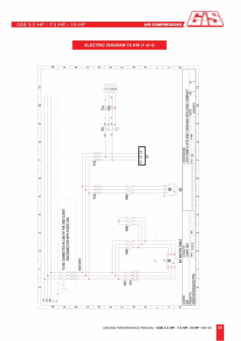
TO B
E CO
NNEC
TED
IN L
INE
BY T
HE E
ND C
LIEN
T DI
SCON
NECT
OR W
ITH
FUSE
S 20
A
M1
MOT
OR C
ABLE
ELECTRIC DIAGRAM 7.5 KW (1 of 4)
GSE 5.5 HP - 7.5 HP - 10 HP
48 USE AND MAINTENANCE MANUAL • GSE 5.5 HP - 7.5 HP- 10 HP • REV. 00
01
23
45
67
89
1011
01
23
45
67
89
1011
@ A B C D E F G H I J K
@ A B C D E F G H I J K
GIS
CARP
I -MO-
PROG
ETTO
:DA
TA:
.VER:ATAD
01.02
.13FG
.:DI
2
DESC
RIZIONE
:AV
V.COM
P.A VI
TE G
SE 7,
5KW
/400
V SCH
.LOGI
C COM
PACT
:AMRIF:.SID
RSGI
S007
5K3G
S202
30.PR
G04
/09/20
144
CLIEN
TE:
LOCA
LITA':
16
45
2 002 00
12
M1
02
KM1
32
1
KM4
0 0
2
2
0
39
88S1
12 13
10 02
02
FR1CF
00
02
1312
10
14
M3M2
U1
KM3
KM2
KM3
KM2
5
5
6 7
34
56
1516
17
YEV1
SOLE
NOID
VAL
VE C
ABLE
11
4
18
42
3
PROB
E TRAN
SD.
PRESS.GAUGE CABLE
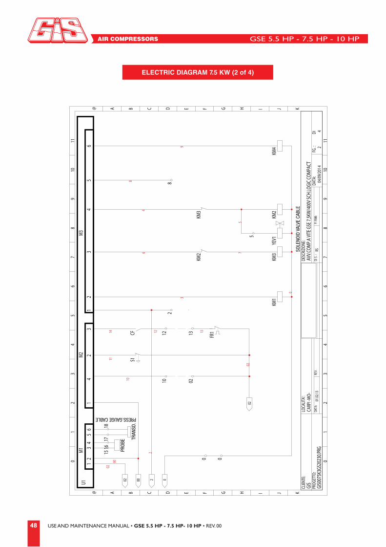
ELECTRIC DIAGRAM 7.5 KW (2 of 4)

GSE 5.5 HP - 7.5 HP - 10 HP
49USE AND MAINTENANCE MANUAL • GSE 5.5 HP - 7.5 HP- 10 HP • REV. 00
PROB
E
PRES
SURE
GAU
GETR
ANSD
UCER
ELECTRIC DIAGRAM 7.5 KW (3 of 4)
GSE 5.5 HP - 7.5 HP - 10 HP
50 USE AND MAINTENANCE MANUAL • GSE 5.5 HP - 7.5 HP- 10 HP • REV. 00
01
23
45
67
89
1011
01
23
45
67
89
1011
@ A B C D E F G H I J K
@ A B C D E F G H I J K
GIS
CARP
I -M
O-
PROG
ETTO
:DA
TA:
.VER:ATAD
01.0
2.13
FG.:
DI4
DESC
RIZI
ONE:
AVV.
COM
P.A
VITE
GSE
7,5
KW/4
00V
SCH.
LOGI
C CO
MPA
CT:AMRIF
:.SIDRS
GIS0
075K
3GS2
0230
.PRG
05/0
6/20
144
CLIE
NTE:
LOCA
LITA
':
EMER
GEN
ZA S
TOP
TRAS
FITA
LIA
TRAS
FORM
ATO
RE 1
00VA
IU10
0038
3
FUSI
BILI
M2
FUSI
BILI
AUX
FUSI
BILI
AUX
FUSI
BILI
AUX
WIM
EX
WIM
EX
WIM
EX
WIM
EX
10X3
8 4A
10X3
8 2A
10X3
8 4A
10X3
8 2A
CONT
ATTO
RE M
1
CONT
ATTO
RE M
1
CONT
ATTO
RE M
1CO
NTAT
TORE
M2
MO
ELLE
R
MO
ELLE
R RELLEOMOCI
MRET 'ELER
DILM
12-1
0-24
V
DILE
M-1
0-24
V
0-40
0/0-
12-2
4V
44MC15APDIZZAVAG
ISAF AZNEUQES 'ELER
ELTE
NEF
B/40
SCHE
DA C
ONT
ROLL
OG
IS
V42-10-21MLIDRELLEOM
V42-10-90MLIDRELLEOM
SIG
ALOVLAVORTTELE
GIS
PRES
SOST
ATO
TR1
KM1
FU2
FU3
FU4
FU5
KM4
FR1
CF S1 U1KM2
KM3
YEV1
TRAS
D. -
TRAN
SD.
ZB12
-10
6-10
A
DESC
RIZI
ONE
DESC
RIPT
ION
CODE
CODI
CEMA
NUFA
CTUR
ERCO
STRU
TTOR
ETY
PETI
POFU
SES
M2
FUSE
S AU
XFU
SES
AUX
FUSE
S AU
XCO
NTAC
TOR
M1
CONT
ACTO
R M
1CO
NTAC
TOR
M1
CONT
ACTO
R M
2TH
ERM
AL R
ELAY
TRAN
SFOR
MER
100
VAPH
ASE
SEQU
ENCE
REL
AY
EMER
GENC
Y ST
OPCH
ECK
SHEE
TSO
LENO
ID V
ALVE
PR
ESSU
RE G
AUGE
COMPONENT DESCRIPTION 7.5 KW (4 of 4)
GSE 5.5 HP - 7.5 HP - 10 HP
51USE AND MAINTENANCE MANUAL • GSE 5.5 HP - 7.5 HP- 10 HP • REV. 00
TEST CERTIFICATE
This certifies that the compressor passed the factory tests.
The following checks were carried out:
• All components were correctly assembled and work properly;
• The electrical tests were completed with positive results;
• The parts subject to pressure were tested with positive results;
• The oil and air circuits have no leaks;
• The outside of the machine has no visual defects;
• The air yield, absorbed power and working temperature parameters are regular.
The tester

GSE 5.5 HP - 7.5 HP - 10 HP
52 USE AND MAINTENANCE MANUAL • GSE 5.5 HP - 7.5 HP- 10 HP • REV. 00
DICHIARAZIONE DI CONFORMITÀ CE
DÉCLARATION DE CONFORMITÉ CE
CE - CONFORMITY DECLARATION
CE - ÜBEREINSTIMMUNGSERKLÄRUNG
DECLARACIÓN DE CONFORMIDAD CE
La GIS S.r.l. con sede legale in Via Dei Barrocciai, 29 - 41012 Carpi (MO) Italy, dichiara che l’elettrocompressore d’aria descritto nel presente libretto, con numero di matricola e anno di costruzione sotto indicati, è conforme alle seguenti disposizioni:Direttiva: 2006/42/CEDirettiva: 2004/108/CE: compatibilità elettromagnetica e successive modificheDirettiva 2006/95/CE: bassa tensione e norme pertinenti
Il rappresentante legaleGianfranco Sgarbi
Fascicolo tecnico - Dossier techniqueTechnical file - Techn. Dokumentation
La Sté. GIS S.r.l. avec son siège en Via Dei Barrocciai, 29 - 41012 Carpi (MO) Italy, déclare que l’électrocompresseur d’air décrit dans cette notice, avec numéro de série et année de fabrication comme spécié ci-dessous, est conforme aux dispositions suivantes:Directive: 2006/42/CEDirective: 2004/108/CE: compatibilité électromagnétique et modications suivantesDirective 2006/95/CE: basse tension et normes pertinentes
Le réprésentant légalGianfranco Sgarbi
Messrs. GIS S.r.l. with headquarters in Via Dei Barrocciai, 29 - 41012 Carpi (MO) Italy, declare that the air electrocompressor described in this manual, with serial No. and year of manufacture as specied below, complies with the following regulations:Directive: 2006/42/CEDirective: 2004/108/CE: electromagnetic compatibility and following modicationsDirective 2006/95/CE: low voltage and relevant rules
The legal rapresentativeGianfranco Sgarbi
Nr. di matricola/Modello Seriennummer/TypNr. de série Número de serie/ModeloSerial number/Model
Anno di costruzione BaujahrAnnée de fabrication Año de fabricaciónYear of manufacture
Die Firma GIS S.r.l. mit Sitz in Via Dei Barrocciai, 29 - 41012 Carpi (MO) Italy, erklärt, daß der in dieser Betriebsanleitunfg beschriebene Elektroluftkonpressor, mit der folgenden Serienummer und dem folgenden Baujahr die folgenden Direktiven entspricht:Richtlinie: 2006/42/CERichtlinie: 2004/108/CE: elektromagnetische Kompatibilität und folgende ÄnderungenRichtlinie 2006/95/CE: Niederspannung und dazu gehörige Richtlinien
Der gesetzliche VertreterGianfranco Sgarbi
La sociedad GIS S.r.l. con sede en Via Dei Barrocciai, 29 - 41012 Carpi (MO) Italy, declara que el electrocompresor de aire descrito en este manual, con número de serie y año de fabricación como se detalla abajo, está conforme con las disposiciones siguientes:Directiva: 2006/42/CEDirectiva: 2004/108/CE: compatibilidad electromagnética y sucesivas modificacionesDirectiva 2006/95/CE: baja tensión y normas pertinentes
El representante legalGianfranco Sgarbi
GIS S.r.l.Via dei Barrocciai, 2941012 CARPI (MO) Italy
I
F
GB
E
D


GIS Srl di GIORGIO SGARBI & C. Via dei Barrocciai, 29 - 41012 Carpi (MO) Italy Tel. +39 059.657018 - Fax +39 059.657028www.gis-air.com [email protected]