usai technology serv ices co., ltd
TRANSCRIPT
Report No.: S0701312 Page 4 / 43
Usai Technology Serv ices Co., Ltd.
General remarks:
Clause number between brackets refer to clauses in
EN61558-1 "(see remark #)" refers to a remark appended to the report. "(see appended table)" refers to a table appended to the report. Throughout this report a comma is used as the decimal separator. The test results presented in this report relate only to the object tested. This report shall not be reproduced except in full without the written approval of the testing laboratory. Unless otherwise specified, test are made under normal conditions at an ambient temperature within the range of 10 to 30, RH45% to 75% and an air pressure of 860mbar of 1060mbar
Enclosed :
6 pages of technical specification of the product
Brief description of the samples:
These products are direct plug-in AC/DC Adapters for general use.
The insulation class of transformers is declared as class B and core size is 41 mm(Length) x 33 mm(Width) x 21.0mm(Thickness)
Primary winding: 2500 turns, Φ0.11mm
Secondary winding: 209 turns, Φ0.37mm
The overall dimension: 63mm x 51mm x 42mm The PCB is equipped with four diodes and one E cap.

Report No.: S0701312 Page 5 / 43
Usai Technology Serv ices Co., Ltd.
Artwork of Marking Label
EN61558-2-6 Clause Requirement Observation Verdict
Report No.: S0701312 Page 6 / 43
Usai Technology Serv ices Co., Ltd.
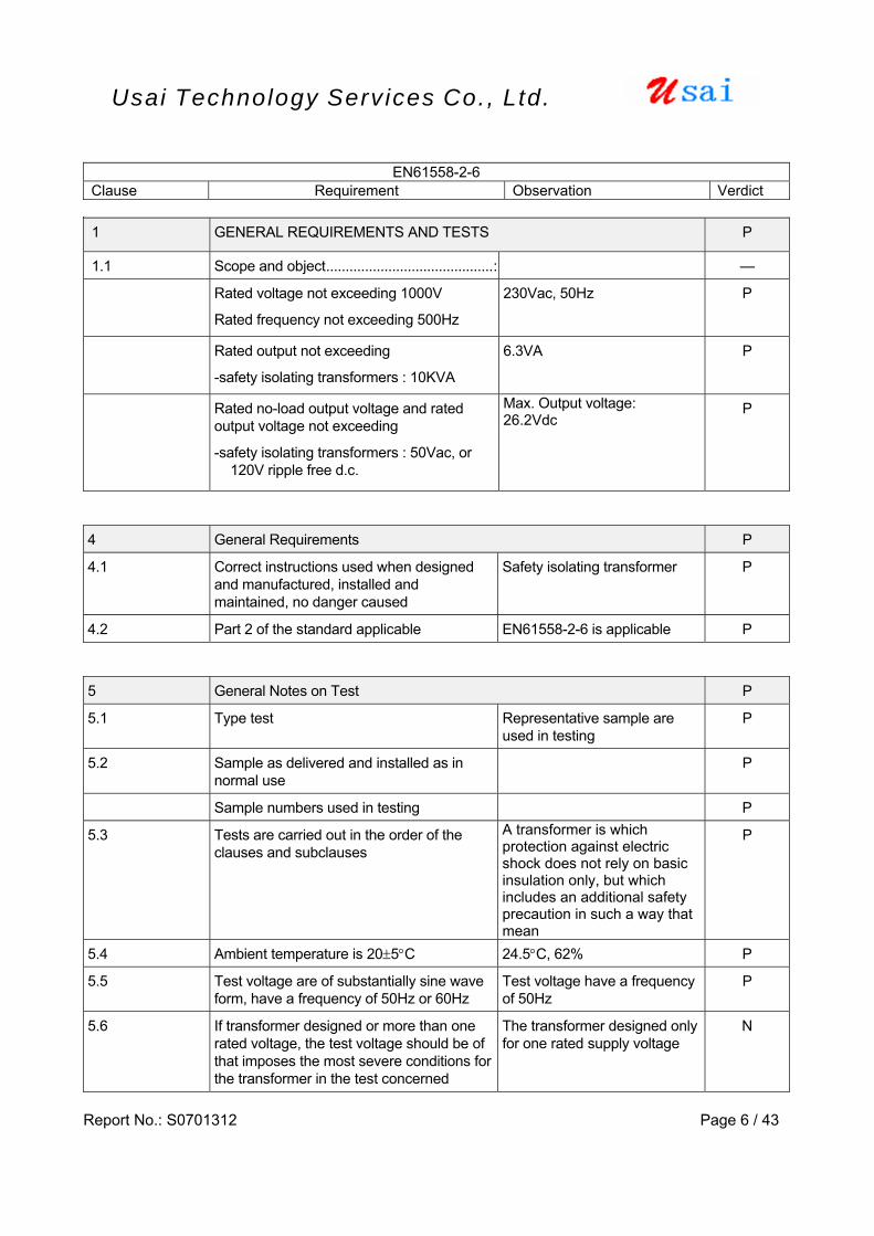
1 GENERAL REQUIREMENTS AND TESTS P
1.1 Scope and object...........................................: —
Rated voltage not exceeding 1000V
Rated frequency not exceeding 500Hz
230Vac, 50Hz P
Rated output not exceeding
-safety isolating transformers : 10KVA
6.3VA
P
Rated no-load output voltage and rated output voltage not exceeding
-safety isolating transformers : 50Vac, or 120V ripple free d.c.
Max. Output voltage: 26.2Vdc
P
4 General Requirements P
4.1 Correct instructions used when designed and manufactured, installed and maintained, no danger caused
Safety isolating transformer P
4.2 Part 2 of the standard applicable EN61558-2-6 is applicable P 5 General Notes on Test P
5.1 Type test Representative sample are used in testing
P
5.2 Sample as delivered and installed as in normal use
P
Sample numbers used in testing P
5.3 Tests are carried out in the order of the clauses and subclauses
A transformer is which protection against electric shock does not rely on basic insulation only, but which includes an additional safety precaution in such a way that mean
P
5.4 Ambient temperature is 20±5°C 24.5°C, 62% P
5.5 Test voltage are of substantially sine wave form, have a frequency of 50Hz or 60Hz
Test voltage have a frequency of 50Hz
P
5.6 If transformer designed or more than one rated voltage, the test voltage should be of that imposes the most severe conditions for the transformer in the test concerned
The transformer designed only for one rated supply voltage
N

EN61558-2-6 Clause Requirement Observation Verdict
Report No.: S0701312 Page 7 / 43
Usai Technology Serv ices Co., Ltd.
5.7 Measurements are made with instruments which do not appreciably affect the values to be measured.
The test instrument do not affect to the value measured
P
5.8 Transformer with external flexible cable or cords are tested with cords connected to the transformer
P
5.9 Class I transformer have accessible metal parts not connected to protective earthing terminal or contact, and are not separated from hazardous live parts by intermediate metal part
Class II transformer N
5.10 Flush-type transformer P
5.11 Transformer for specific use tested as transformer for general use
Not a transformer for specific use
N
5.12 Associated transformer shall comply with the standard of the appliance which they are intended to be used in
Not a associated transformer N
5.13 IP00 transformer, the use of which is not known, are tested without enclosure
IP20 N
5.14 IP00 transformer, the use of which is known, are tested mounted in accordance with the manufacture’s instructions
N
6. Rating P
6.101 The rated output voltage shall not exceed 50Vac and /or 120V ripple-free dc
Max. output voltage: 26.2Vdc P
6.102 The rated output shall not exceed 10KVA for single-phase transformer and 16KVA for polyphase transformers except for special safety isolating transformer
6.3VA P
6.103 The rated frequency shall not exceed 500Hz 50Hz P
6.104 The rated supply voltage shall not exceed 1000Vac
230Vac P
7. Classification P
7.1 According to their protection against electric shock:
Class II transformer P
7.2 According to short-circuit protection or protection against abnormal use
Fail-safe transformer P
EN61558-2-6 Clause Requirement Observation Verdict
Report No.: S0701312 Page 8 / 43
Usai Technology Serv ices Co., Ltd.
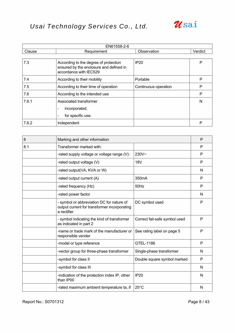
7.3 According to the degree of protection ensured by the enclosure and defined in accordance with IEC529
IP20 P
7.4 According to their mobility Portable P
7.5 According to their time of operation Continuous operation P
7.6 According to the intended use P
7.6.1 Associated transformer
- incorporated;
- for specific use.
N
7.6.2 Independent P 8 Marking and other information P
8.1 Transformer marked with: P
-rated supply voltage or voltage range (V): 230V~ P
-rated output voltage (V) 18V P
-rated output(VA, KVA or W) N
-rated output current (A) 350mA P
-rated frequency (Hz) 50Hz P
-rated power factor N
- symbol or abbreviation DC for nature of output current for transformer incorporating a rectifier
DC symbol used P
- symbol indicating the kind of transformer as indicated in part 2
Correct fail-safe symbol used P
-name or trade mark of the manufacturer or responsible vender
See rating label on page 5 P
-model or type reference GTEL-1186 P
-vector group for three-phase transformer Single-phase transformer N
-symbol for class II Double square symbol marked P
-symbol for class III N
-indication of the protection index IP, other than IP00
IP20 N
-rated maximum ambient temperature ta, if 25°C N

EN61558-2-6 Clause Requirement Observation Verdict
Report No.: S0701312 Page 9 / 43
Usai Technology Serv ices Co., Ltd.
other than 25°C
-operating time for short-time operation or intermittent operation transformer
N
8.2 Transformer with protection index IP00, or associated transformer
N
8.3 Transformer can be adjusted to suit different rated supply voltages, be marked with the voltage to be adjusted to
Not possible to adjust input voltage, only single rated supply voltage
N
8.4 Transformer with tapped or multiple output winding shall be marked with : - rated output voltage for each tapping or
winding, - rated output for each tapping or winding
Only one output winding N
8.5 - short-circuit proof transformer shall be marked with the symbol;
- Non-inherently short-circuit proof transformer, to be protected by fuses, shall be marked with the rated current for the protecting fuse-link, followed or preceded by symbol for the time current characteristics of the fuses;
- No-inherently short –circuit proof transformer with incorporated replaceable protective devices other than fuses, be marked with the manufacturer’s model or type reference of the device and the rating;
- Fail-safe transformer, shall be marked with the symbol for fail-safe transformer
Fail-safe transformer, with fail safe symbol marked
P
8.6 - Neutral terminals marks; Direct plug-in type with two pin flat plug.
N
- Earthing terminal marking; N
- Marks for terminal of input and output N
8.7 Transformer shall be provided with markings clearly indicating the manner in which the transformer is to be connected
Output polarity indicated by the symbol. See rating label on page 5.
P
8.8 Instruction for kinds of attachment type N
8.9 Relevant symbol, of wording, for indoor use transformer
“For indoor use only” symbol marked
P
8.10 Class II transformers symbol See rating label on page 5. P
8.11 Standard symbol See rating label on page 5. P
EN61558-2-6 Clause Requirement Observation Verdict
Report No.: S0701312 Page 10 / 43
Usai Technology Serv ices Co., Ltd.
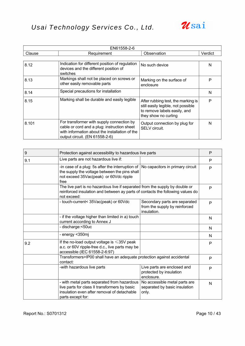
8.12 Indication for different position of regulation devices and the different position of switches
No such device N
8.13 Markings shall not be placed on screws or other easily removable parts
Marking on the surface of enclosure
P
8.14 Special precautions for installation N
8.15 Marking shall be durable and easily legible After rubbing test, the marking is still easily legible, not possible to remove labels easily, and they show no curling
P
8.101 For transformer with supply connection by cable or cord and a plug: instruction sheet with information about the installation of the output circuit. (EN 61558-2-6)
Output connection by plug for SELV circuit.
N
9 Protection against accessibility to hazardous live parts P
9.1 Live parts are not hazardous live if: P
-in case of a plug: 5s after the interruption of the supply the voltage between the pins shall not exceed 35Vac(peak) or 60Vdc ripple free
No capacitors in primary circuit P
The live part is no hazardous live if separated from the supply by double or reinforced insulation and between ay parts of contacts the following values do not exceed:
P
- touch-current< 35Vac(peak) or 60Vdc Secondary parts are separated from the supply by reinforced insulation.
P
- if the voltage higher than limited in a) touch current according to Annex J
N
- discharge:<50uc N
- energy <350mj N
9.2 If the no-load output voltage is ≤35V peak a.c. or 60V ripple-free d.c., live parts may be accessible (IEC 61558-2-6:97)
P
Transformers>IP00 shall have an adequate protection against accidental contact:
P
-with hazardous live parts Live parts are enclosed and protected by insulation enclosure.
P
- with metal parts separated from hazardous live parts for class II transformers by basic insulation even after removal of detachable parts except for:
No accessible metal parts are separated by basic insulation only.
N
EN61558-2-6 Clause Requirement Observation Verdict
Report No.: S0701312 Page 11 / 43
Usai Technology Serv ices Co., Ltd.
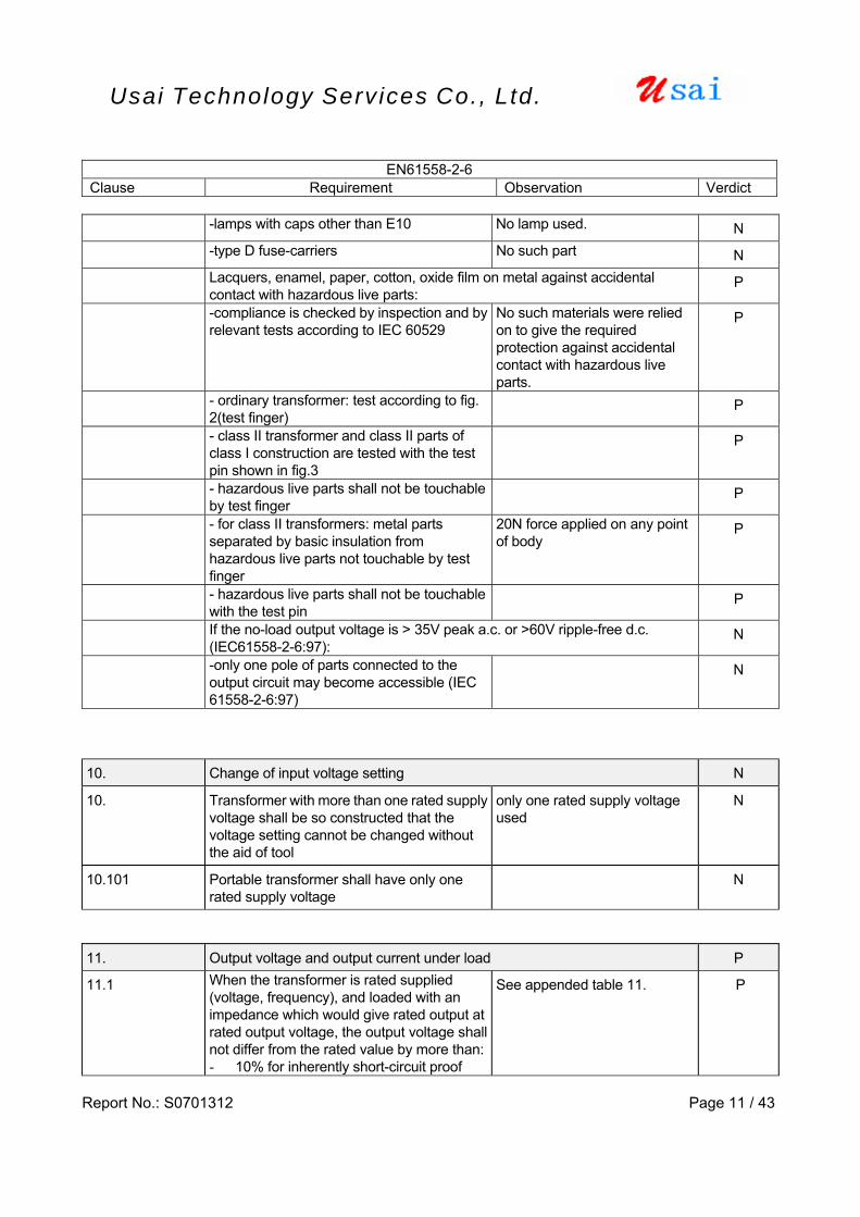
-lamps with caps other than E10 No lamp used. N
-type D fuse-carriers No such part N
Lacquers, enamel, paper, cotton, oxide film on metal against accidental contact with hazardous live parts:
P
-compliance is checked by inspection and by relevant tests according to IEC 60529
No such materials were relied on to give the required protection against accidental contact with hazardous live parts.
P
- ordinary transformer: test according to fig. 2(test finger)
P
- class II transformer and class II parts of class I construction are tested with the test pin shown in fig.3
P
- hazardous live parts shall not be touchable by test finger
P
- for class II transformers: metal parts separated by basic insulation from hazardous live parts not touchable by test finger
20N force applied on any point of body
P
- hazardous live parts shall not be touchable with the test pin
P
If the no-load output voltage is > 35V peak a.c. or >60V ripple-free d.c. (IEC61558-2-6:97):
N
-only one pole of parts connected to the output circuit may become accessible (IEC 61558-2-6:97)
N
10. Change of input voltage setting N
10. Transformer with more than one rated supply voltage shall be so constructed that the voltage setting cannot be changed without the aid of tool
only one rated supply voltage used
N
10.101 Portable transformer shall have only one rated supply voltage
N
11. Output voltage and output current under load P
11.1 When the transformer is rated supplied (voltage, frequency), and loaded with an impedance which would give rated output at rated output voltage, the output voltage shall not differ from the rated value by more than:- 10% for inherently short-circuit proof
See appended table 11. P
EN61558-2-6 Clause Requirement Observation Verdict
Report No.: S0701312 Page 12 / 43
Usai Technology Serv ices Co., Ltd.
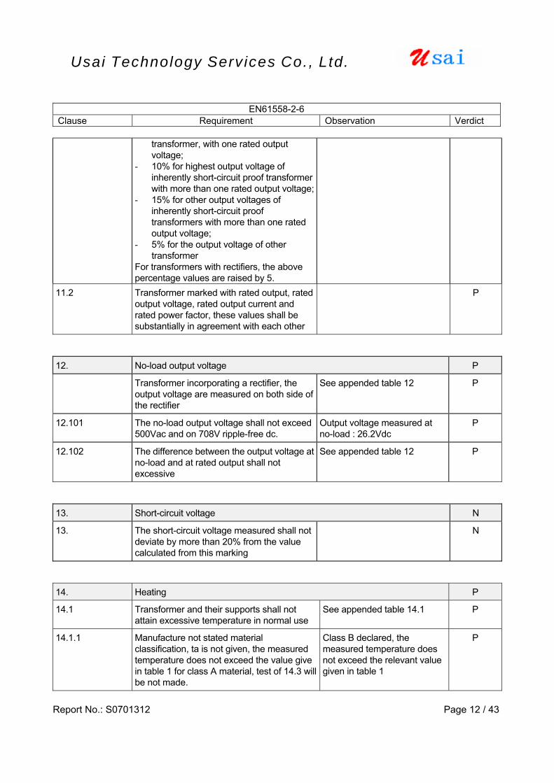
transformer, with one rated output voltage;
- 10% for highest output voltage of inherently short-circuit proof transformer with more than one rated output voltage;
- 15% for other output voltages of inherently short-circuit proof transformers with more than one rated output voltage;
- 5% for the output voltage of other transformer
For transformers with rectifiers, the above percentage values are raised by 5.
11.2 Transformer marked with rated output, rated output voltage, rated output current and rated power factor, these values shall be substantially in agreement with each other
P
12. No-load output voltage P
Transformer incorporating a rectifier, the output voltage are measured on both side of the rectifier
See appended table 12 P
12.101 The no-load output voltage shall not exceed 500Vac and on 708V ripple-free dc.
Output voltage measured at no-load : 26.2Vdc
P
12.102 The difference between the output voltage at no-load and at rated output shall not excessive
See appended table 12 P
13. Short-circuit voltage N
13. The short-circuit voltage measured shall not deviate by more than 20% from the value calculated from this marking
N
14. Heating P
14.1 Transformer and their supports shall not attain excessive temperature in normal use
See appended table 14.1 P
14.1.1 Manufacture not stated material classification, ta is not given, the measured temperature does not exceed the value give in table 1 for class A material, test of 14.3 will be not made.
Class B declared, the measured temperature does not exceed the relevant value given in table 1
P

EN61558-2-6 Clause Requirement Observation Verdict
Report No.: S0701312 Page 13 / 43
Usai Technology Serv ices Co., Ltd.
14.1.2 Manufacture not stated material classification, but ta is given, the measured temperature does not exceed the value give in table 1 for class A material, taking the value of ta into account, test of 14.3 will be not made.
N
14.1.3 Manufacture has stated the classification of the material, but has not stated the value of ta, if the measured temperature do not exceed the relevant value given in table 1, test of 14.3 are not made
N
14.2 The temperatures are determined under the correct condition when steady state is established.
P
Upri (V):1.06 times rated supply voltage 230×1.06= 243.8 P
Room temperature: rated ambient temperature ()
25.0 P
Temperature of windings by thermocouple method:
P
- Class A: ≤100 N
- Class E: ≤115 N
- Class B: ≤120 P
- Class F: ≤140 N
- Class H: ≤165 N
Dielectric strength test followed Pri. and sec. winging:
4200 VAC, 1min.
Pri. And enclosure :
4200 VAC, 1min.
P
14.3 Live parts cycling test : 10 cycles
- Heat run:
- Moisture treatment: 93%, 48 hours
- Vibration test: 10-55-10Hz, 30min, 0.35mm
N
15. Short circuit and overload protection P
15.1 Transformer shall not become unsafe due to See appended table 15 P
EN61558-2-6 Clause Requirement Observation Verdict
Report No.: S0701312 Page 14 / 43
Usai Technology Serv ices Co., Ltd.
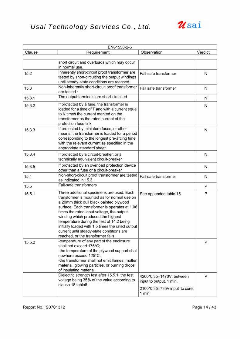
short circuit and overloads which may occur in normal use.
15.2 Inherently short-circuit proof transformer are tested by short-circuiting the output windings until steady-state conditions are reached
Fail-safe transformer N
15.3 Non-inherently short-circuit proof transformer are tested :
Fail safe transformer N
15.3.1 The output terminals are short-circuited N
15.3.2 If protected by a fuse, the transformer is loaded for a time of T and with a current equal to K times the current marked on the transformer as the rated current of the protection fuse-link.
N
15.3.3 If protected by miniature fuses, or other means, the transformer is loaded for a period corresponding to the longest pre-arcing time with the relevant current as specified in the appropriate standard sheet.
N
15.3.4 If protected by a circuit-breaker, or a technically equivalent circuit-breaker
N
15.3.5 If protected by an overload protection device other than a fuse or a circuit-breaker
N
15.4 Non-short-circuit proof transformer are tested as indicated in 15.3.
Fail safe transformer N
15.5 Fail-safe transformers P
15.5.1 Three additional specimens are used. Each transformer is mounted as for normal use on a 20mm thick dull black painted plywood surface. Each transformer is operates at 1.06 times the rated input voltage, the output winding which produced the highest temperature during the test of 14.2 being initially loaded with 1.5 times the rated output current until steady-state conditions are reached, or the transformer fails.
See appended table 15 P
15.5.2 -temperature of any part of the enclosure shall not exceed 175°C; -the temperature of the plywood support shall nowhere exceed 125°C; -the transformer shall not emit flames, molten material, glowing particles, or burning drops of insulating material.
P
Dielectric strength test after 15.5.1, the test voltage being 35% of the value according to clause 18 table8.
4200*0.35=1470V, between input to output, 1 min.
2100*0.35=735V input to core, 1 min
P
EN61558-2-6 Clause Requirement Observation Verdict
Report No.: S0701312 Page 15 / 43
Usai Technology Serv ices Co., Ltd.
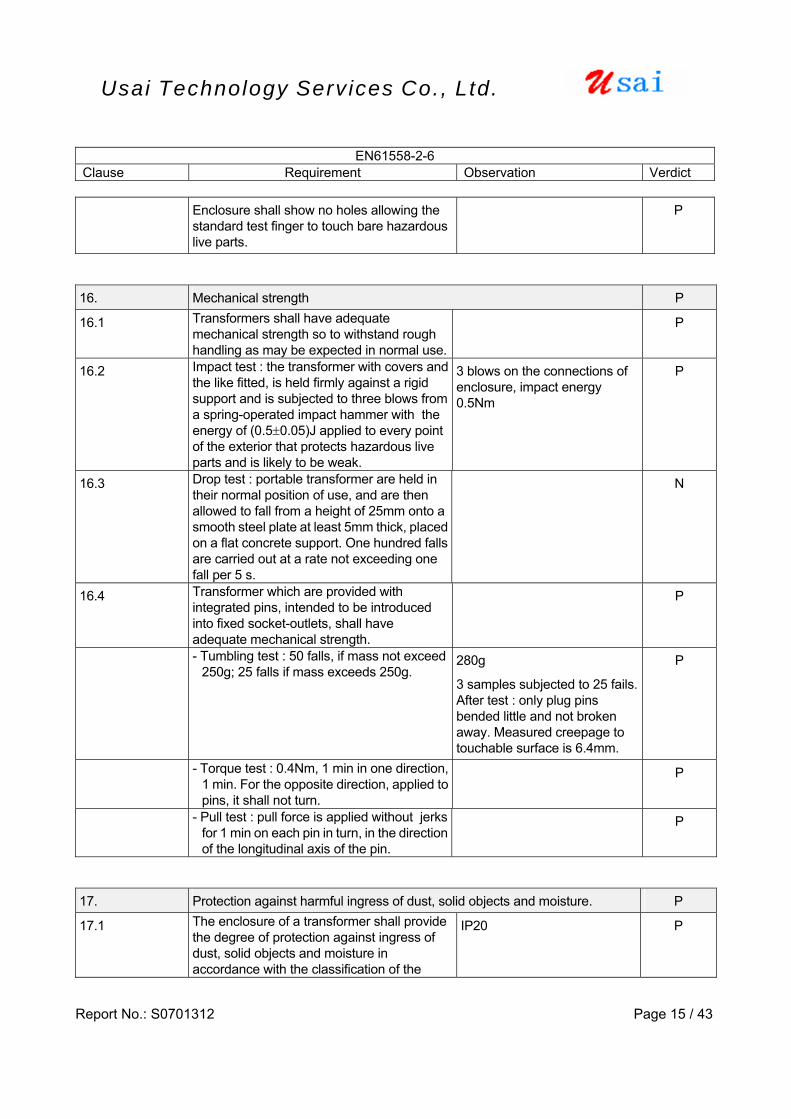
Enclosure shall show no holes allowing the standard test finger to touch bare hazardous live parts.
P
16. Mechanical strength P
16.1 Transformers shall have adequate mechanical strength so to withstand rough handling as may be expected in normal use.
P
16.2 Impact test : the transformer with covers and the like fitted, is held firmly against a rigid support and is subjected to three blows from a spring-operated impact hammer with the energy of (0.5±0.05)J applied to every point of the exterior that protects hazardous live parts and is likely to be weak.
3 blows on the connections of enclosure, impact energy 0.5Nm
P
16.3 Drop test : portable transformer are held in their normal position of use, and are then allowed to fall from a height of 25mm onto a smooth steel plate at least 5mm thick, placed on a flat concrete support. One hundred falls are carried out at a rate not exceeding one fall per 5 s.
N
16.4 Transformer which are provided with integrated pins, intended to be introduced into fixed socket-outlets, shall have adequate mechanical strength.
P
- Tumbling test : 50 falls, if mass not exceed 250g; 25 falls if mass exceeds 250g.
280g
3 samples subjected to 25 fails. After test : only plug pins bended little and not broken away. Measured creepage to touchable surface is 6.4mm.
P
- Torque test : 0.4Nm, 1 min in one direction, 1 min. For the opposite direction, applied to pins, it shall not turn.
P
- Pull test : pull force is applied without jerks for 1 min on each pin in turn, in the direction of the longitudinal axis of the pin.
P
17. Protection against harmful ingress of dust, solid objects and moisture. P
17.1 The enclosure of a transformer shall provide the degree of protection against ingress of dust, solid objects and moisture in accordance with the classification of the
IP20
P

EN61558-2-6 Clause Requirement Observation Verdict
Report No.: S0701312 Page 16 / 43
Usai Technology Serv ices Co., Ltd.
transformer and the IP number marked on the transformer.
17.1.1 Tests P
- Solid-object-proof (first characteristic IP numeral 2) :
IP20, test finger and test pin applied, no live parts were accessible
P
- Solid-object-proof (first characteristic IP numerals 3 and 4) :
N
- Dust-proof transformer (first characteristic IP numeral 6):
N
- Dust-tight transformer (first characteristic IP numeral 6) :
N
- Drip-proof transformer (second characteristic IP numeral 1) :
N
- Rain-proof transformer (second characteristic IP numeral 3) :
N
- Splash-proof transformer (second characteristic IP numeral 4) :
N
- Jet-proof transformer (second characteristic IP numeral 5) :
N
- Water-tight transformer (second characteristic IP numeral 7) :
N
- Pressure watertight transformer (second characteristic IP numeral 8) :
N
17.2 Humid treatment :is carried out in a humidity cabinet with relative humidity maintained between, temperature 91-95%; 20-30°C, the specimen is kept in the cabinet for - 48hours for ordinary transformer; - 168 hours for other transformer
Insulation and electric strength test according to Cl.18 after 48h, 25, 93%RH test.
P
18. Insulation resistance and dielectric strength P
18.1 The test is made immediately after the test of 17.2, in the humidity cabinet or in the room in which the specimen was brought to the prescribed temperature, after reassembling those parts which may have been removed.
P
18.2 The insulation resistance is measured with a dc voltage of approximately 500V applied, the measurement being made 1 min after application of the voltage.
The measured insulation resistance is more 500 MΩ
P
18.3 Immediately after the test of 18.2, the insulation is subjected for 1 min to a voltage of substantially sine-wave form at 50/60 Hz. Resistors, capacitors and other components are disconnected before carrying out the
4200 V applied between primary and output,
After the thermal fuse opened, test applied at the different
P

EN61558-2-6 Clause Requirement Observation Verdict
Report No.: S0701312 Page 17 / 43
Usai Technology Serv ices Co., Ltd.
test. polarity of pri. Winding: 2100Vac
18.4 After the test of 18.3, the input circuit is connected to a voltage equal to double the rated supply voltage, at double the rated frequency for 5 min. No load is connected to the transformer. During the test, there shall be no breakdown of the insulation.
2x230=460V, 2x50=100Hz for 5 min, no load.
P
19. Construction P
19.1 The input and output circuits shall be electrically separated from each other, and shall have not possibility of any interconnection, either directly or indirectly, through other metal parts
P
19.1.1 The insulation between the input and output winding(s) shall consist of double or reinforced insulation. In addition, - for class I transformer, the insulation
shall consist of basic insulation, and the insulation between the output windings and the body shall consist of supplementary insulation;
- for class II transformer, the insulation between input windings and the body, and between the output windings and the body, shall consist of double or reinforced insulation.
Reinforce or double insulation between input windings and output
P
19.1.2 Insulation via intermediate metal : - for class I transformer, the insulation
between input and output windings via the intermediate metal part shall consist of double or reinforced insulation;
- for class II transformer, the insulation between the input and the body, and between the output windings and the body via the intermediate metal shall consist of double or reinforced insulation.
- The insulation between the intermediate metal part and the input or output windings shall in both cases consist of at least basic insulation.
P
19.1.3 For class I transformers, the insulation between the input and output windings may consist of basic insulation plus protective screening instead of double or reinforced
Class II transformer N
EN61558-2-6 Clause Requirement Observation Verdict
Report No.: S0701312 Page 18 / 43
Usai Technology Serv ices Co., Ltd.
insulation.
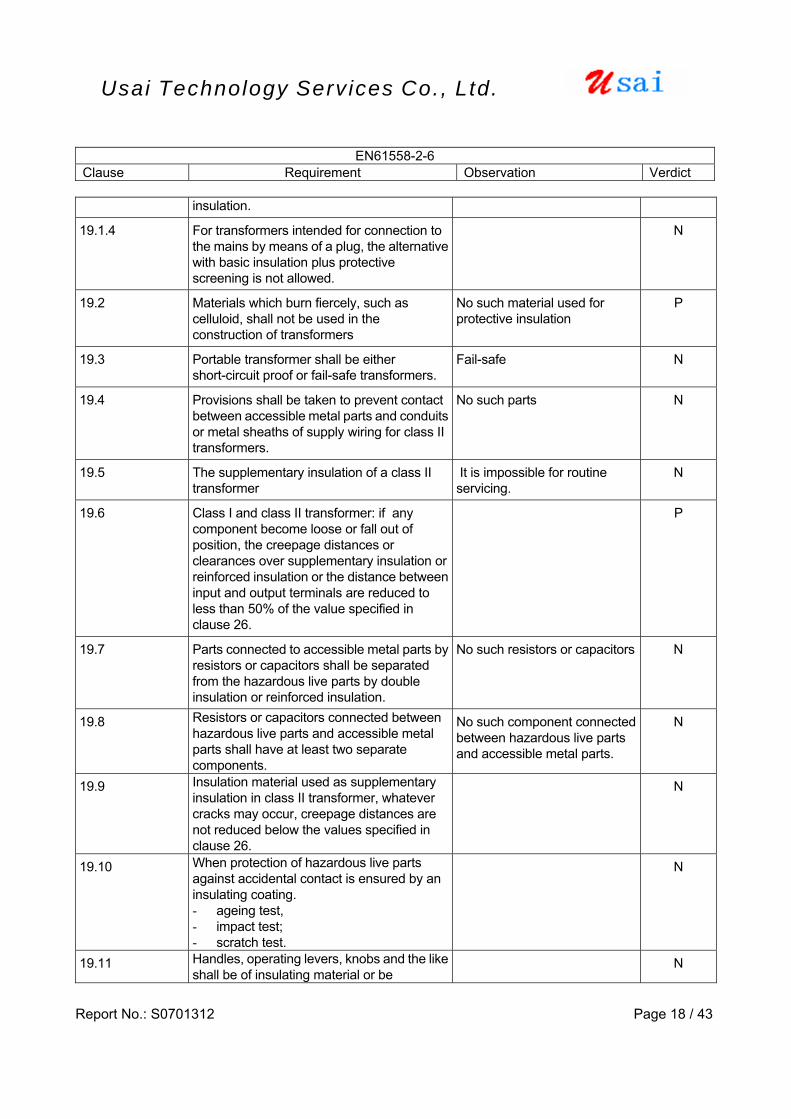
19.1.4 For transformers intended for connection to the mains by means of a plug, the alternative with basic insulation plus protective screening is not allowed.
N
19.2 Materials which burn fiercely, such as celluloid, shall not be used in the construction of transformers
No such material used for protective insulation
P
19.3 Portable transformer shall be either short-circuit proof or fail-safe transformers.
Fail-safe N
19.4 Provisions shall be taken to prevent contact between accessible metal parts and conduits or metal sheaths of supply wiring for class II transformers.
No such parts N
19.5 The supplementary insulation of a class II transformer
It is impossible for routine servicing.
N
19.6 Class I and class II transformer: if any component become loose or fall out of position, the creepage distances or clearances over supplementary insulation or reinforced insulation or the distance between input and output terminals are reduced to less than 50% of the value specified in clause 26.
P
19.7 Parts connected to accessible metal parts by resistors or capacitors shall be separated from the hazardous live parts by double insulation or reinforced insulation.
No such resistors or capacitors N
19.8 Resistors or capacitors connected between hazardous live parts and accessible metal parts shall have at least two separate components.
No such component connected between hazardous live parts and accessible metal parts.
N
19.9 Insulation material used as supplementary insulation in class II transformer, whatever cracks may occur, creepage distances are not reduced below the values specified in clause 26.
N
19.10 When protection of hazardous live parts against accidental contact is ensured by an insulating coating. - ageing test, - impact test; - scratch test.
N
19.11 Handles, operating levers, knobs and the like shall be of insulating material or be
N
EN61558-2-6 Clause Requirement Observation Verdict
Report No.: S0701312 Page 19 / 43
Usai Technology Serv ices Co., Ltd.
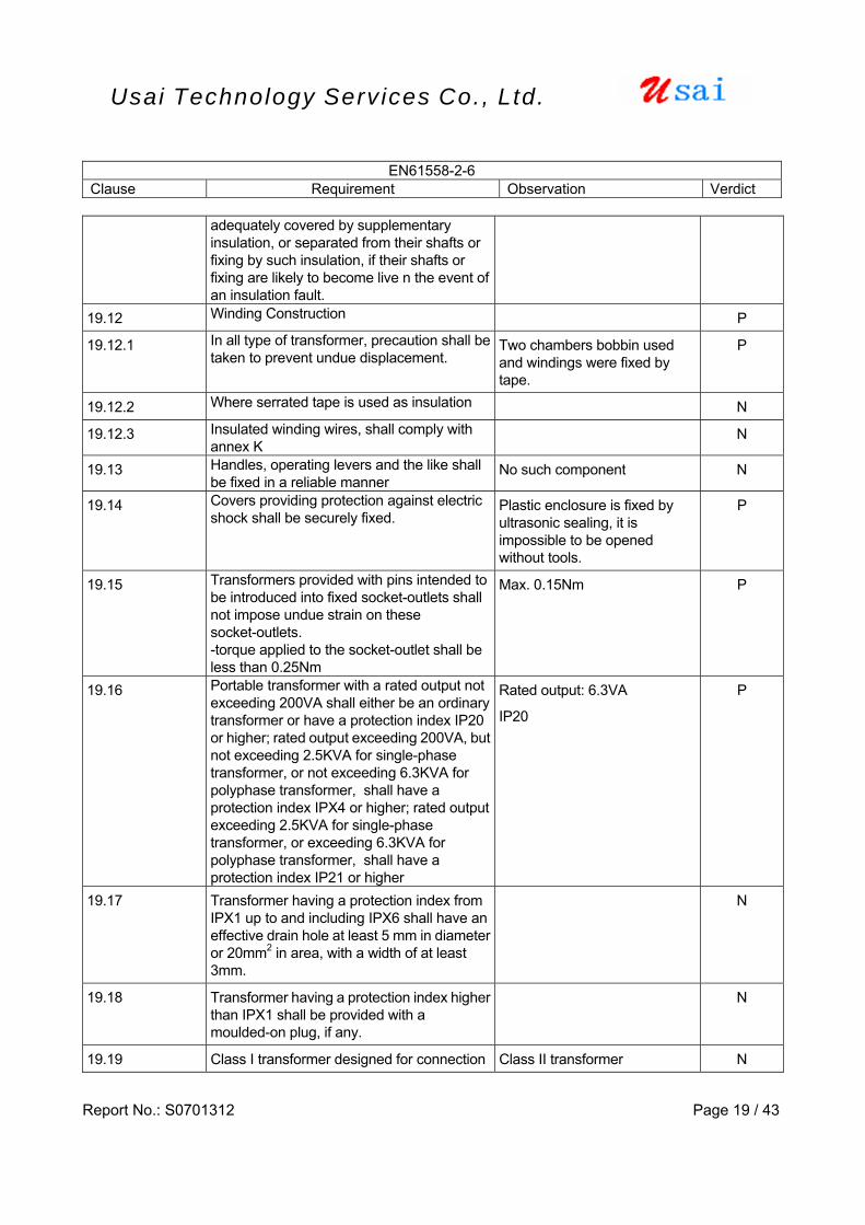
adequately covered by supplementary insulation, or separated from their shafts or fixing by such insulation, if their shafts or fixing are likely to become live n the event of an insulation fault.
19.12 Winding Construction P
19.12.1 In all type of transformer, precaution shall be taken to prevent undue displacement.
Two chambers bobbin used and windings were fixed by tape.
P
19.12.2 Where serrated tape is used as insulation N
19.12.3 Insulated winding wires, shall comply with annex K
N
19.13 Handles, operating levers and the like shall be fixed in a reliable manner
No such component N
19.14 Covers providing protection against electric shock shall be securely fixed.
Plastic enclosure is fixed by ultrasonic sealing, it is impossible to be opened without tools.
P
19.15 Transformers provided with pins intended to be introduced into fixed socket-outlets shall not impose undue strain on these socket-outlets. -torque applied to the socket-outlet shall be less than 0.25Nm
Max. 0.15Nm P
19.16 Portable transformer with a rated output not exceeding 200VA shall either be an ordinary transformer or have a protection index IP20 or higher; rated output exceeding 200VA, but not exceeding 2.5KVA for single-phase transformer, or not exceeding 6.3KVA for polyphase transformer, shall have a protection index IPX4 or higher; rated output exceeding 2.5KVA for single-phase transformer, or exceeding 6.3KVA for polyphase transformer, shall have a protection index IP21 or higher
Rated output: 6.3VA
IP20
P
19.17 Transformer having a protection index from IPX1 up to and including IPX6 shall have an effective drain hole at least 5 mm in diameter or 20mm2 in area, with a width of at least 3mm.
N
19.18 Transformer having a protection index higher than IPX1 shall be provided with a moulded-on plug, if any.
N
19.19 Class I transformer designed for connection Class II transformer N
EN61558-2-6 Clause Requirement Observation Verdict
Report No.: S0701312 Page 20 / 43
Usai Technology Serv ices Co., Ltd.
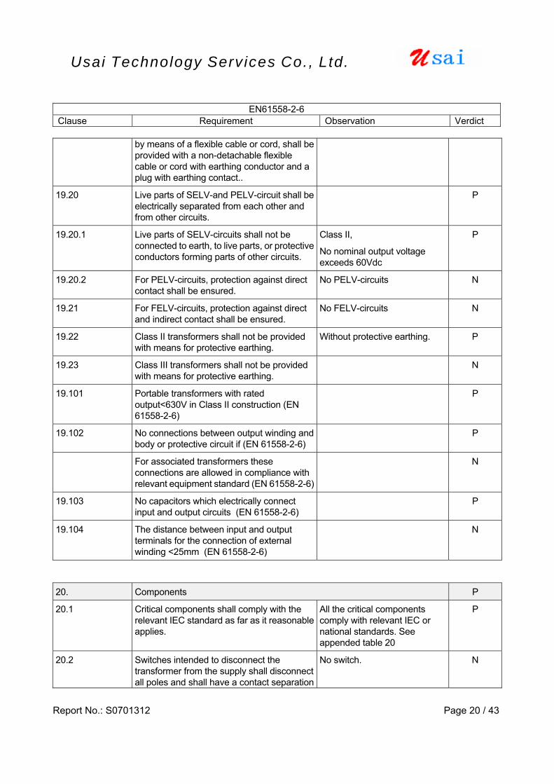
by means of a flexible cable or cord, shall be provided with a non-detachable flexible cable or cord with earthing conductor and a plug with earthing contact..
19.20 Live parts of SELV-and PELV-circuit shall be electrically separated from each other and from other circuits.
P
19.20.1 Live parts of SELV-circuits shall not be connected to earth, to live parts, or protective conductors forming parts of other circuits.
Class II,
No nominal output voltage exceeds 60Vdc
P
19.20.2 For PELV-circuits, protection against direct contact shall be ensured.
No PELV-circuits N
19.21 For FELV-circuits, protection against direct and indirect contact shall be ensured.
No FELV-circuits N
19.22 Class II transformers shall not be provided with means for protective earthing.
Without protective earthing. P
19.23 Class III transformers shall not be provided with means for protective earthing.
N
19.101 Portable transformers with rated output<630V in Class II construction (EN 61558-2-6)
P
19.102 No connections between output winding and body or protective circuit if (EN 61558-2-6)
P
For associated transformers these connections are allowed in compliance with relevant equipment standard (EN 61558-2-6)
N
19.103 No capacitors which electrically connect input and output circuits (EN 61558-2-6)
P
19.104 The distance between input and output terminals for the connection of external winding <25mm (EN 61558-2-6)
N
20. Components P
20.1 Critical components shall comply with the relevant IEC standard as far as it reasonable applies.
All the critical components comply with relevant IEC or national standards. See appended table 20
P
20.2 Switches intended to disconnect the transformer from the supply shall disconnect all poles and shall have a contact separation
No switch. N
EN61558-2-6 Clause Requirement Observation Verdict
Report No.: S0701312 Page 21 / 43
Usai Technology Serv ices Co., Ltd.
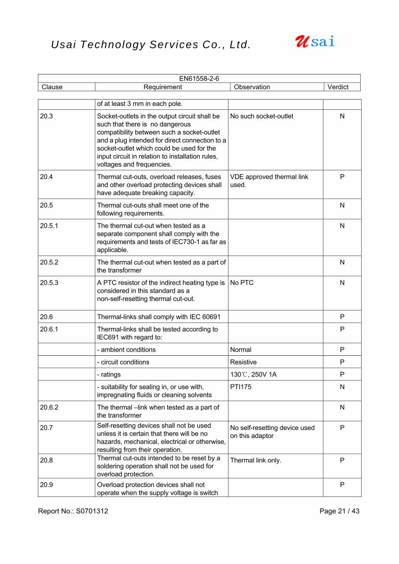
of at least 3 mm in each pole.
20.3 Socket-outlets in the output circuit shall be such that there is no dangerous compatibility between such a socket-outlet and a plug intended for direct connection to a socket-outlet which could be used for the input circuit in relation to installation rules, voltages and frequencies.
No such socket-outlet N
20.4 Thermal cut-outs, overload releases, fuses and other overload protecting devices shall have adequate breaking capacity.
VDE approved thermal link used.
P
20.5 Thermal cut-outs shall meet one of the following requirements.
N
20.5.1 The thermal cut-out when tested as a separate component shall comply with the requirements and tests of IEC730-1 as far as applicable.
N
20.5.2 The thermal cut-out when tested as a part of the transformer
N
20.5.3 A PTC resistor of the indirect heating type is considered in this standard as a non-self-resetting thermal cut-out.
No PTC N
20.6 Thermal-links shall comply with IEC 60691 P
20.6.1 Thermal-links shall be tested according to IEC691 with regard to:
P
- ambient conditions Normal P
- circuit conditions Resistive P
- ratings 130, 250V 1A P
- suitability for sealing in, or use with, impregnating fluids or cleaning solvents
PTI175 N
20.6.2 The thermal –link when tested as a part of the transformer
N
20.7 Self-resetting devices shall not be used unless it is certain that there will be no hazards, mechanical, electrical or otherwise, resulting from their operation.
No self-resetting device used on this adaptor
P
20.8 Thermal cut-outs intended to be reset by a soldering operation shall not be used for overload protection.
Thermal link only. P
20.9 Overload protection devices shall not operate when the supply voltage is switch
P
EN61558-2-6 Clause Requirement Observation Verdict
Report No.: S0701312 Page 22 / 43
Usai Technology Serv ices Co., Ltd.
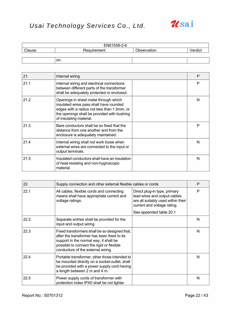
on. 21. Internal wiring P
21.1 Internal wiring and electrical connections between different parts of the transformer shall be adequately protected or enclosed.
P
21.2 Openings in sheet metal through which insulated wires pass shall have rounded edges with a radius not less than 1.5mm, or the openings shall be provided with bushing of insulating material.
N
21.3 Bare conductors shall be so fixed that the distance from one another and from the enclosure is adequately maintained.
P
21.4 Internal wiring shall not work loose when external wires are connected to the input or output terminals.
N
21.5 Insulated conductors shall have an insulation of heat-resisting and non-hygroscopic material.
N
22. Supply connection and other external flexible cables or cords P
22.1 All cables, flexible cords and connecting means shall have appropriate current and voltage ratings.
Direct plug-in type, primary lead wires and output cables are all suitably used within their current and voltage rating.
See appended table 20.1
P
22.2 Separate entries shall be provided for the input and output wiring.
N
22.3 Fixed transformers shall be so designed that, after the transformer has been fixed to its support in the normal way, it shall be possible to connect the rigid or flexible conductors of the external wiring.
N
22.4 Portable transformer, other those intended to be mounted directly on a socket-outlet, shall be provided with a power supply cord having a length between 2 m and 4 m.
N
22.5 Power supply cords of transformer with protection index IPX0 shall be not lighter
N
EN61558-2-6 Clause Requirement Observation Verdict
Report No.: S0701312 Page 23 / 43
Usai Technology Serv ices Co., Ltd.
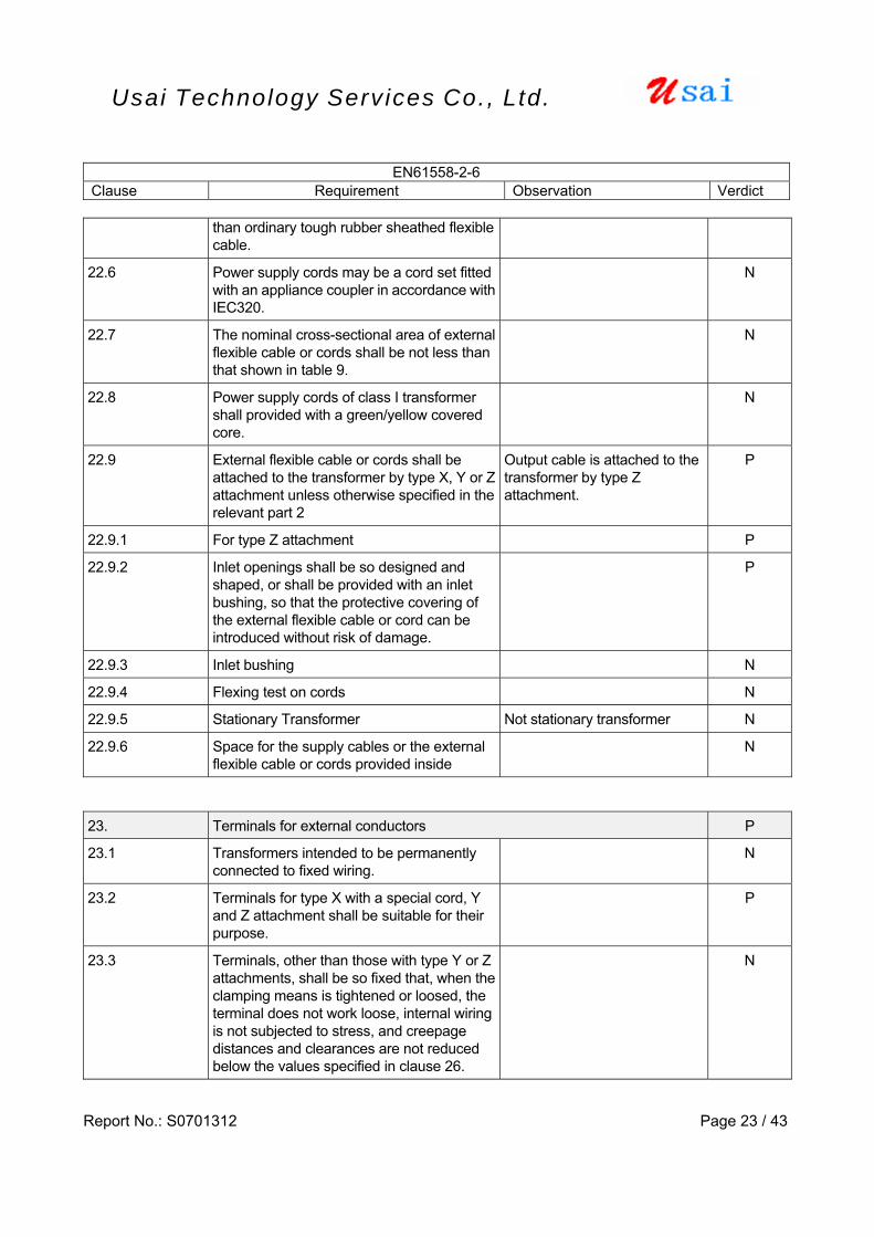
than ordinary tough rubber sheathed flexible cable.
22.6 Power supply cords may be a cord set fitted with an appliance coupler in accordance with IEC320.
N
22.7 The nominal cross-sectional area of external flexible cable or cords shall be not less than that shown in table 9.
N
22.8 Power supply cords of class I transformer shall provided with a green/yellow covered core.
N
22.9 External flexible cable or cords shall be attached to the transformer by type X, Y or Z attachment unless otherwise specified in the relevant part 2
Output cable is attached to the transformer by type Z attachment.
P
22.9.1 For type Z attachment P
22.9.2 Inlet openings shall be so designed and shaped, or shall be provided with an inlet bushing, so that the protective covering of the external flexible cable or cord can be introduced without risk of damage.
P
22.9.3 Inlet bushing N
22.9.4 Flexing test on cords N
22.9.5 Stationary Transformer Not stationary transformer N
22.9.6 Space for the supply cables or the external flexible cable or cords provided inside
N
23. Terminals for external conductors P
23.1 Transformers intended to be permanently connected to fixed wiring.
N
23.2 Terminals for type X with a special cord, Y and Z attachment shall be suitable for their purpose.
P
23.3 Terminals, other than those with type Y or Z attachments, shall be so fixed that, when the clamping means is tightened or loosed, the terminal does not work loose, internal wiring is not subjected to stress, and creepage distances and clearances are not reduced below the values specified in clause 26.
N

EN61558-2-6 Clause Requirement Observation Verdict
Report No.: S0701312 Page 24 / 43
Usai Technology Serv ices Co., Ltd.
23.4 Terminals, other than those with type Y or Z attachments, shall be so designed that they clamp the conductor between metallic surfaces with sufficient contact pressure, and without damage to the conductor.
N
23.5 Terminals provided for the connection to fixed wiring and terminals with type X attachment shall be located near their associated terminals of different polarities and the earthing terminal.
N
23.6 Terminal blocks and similar devices shall not be accessible without the aid of a tool, even if their hazardous live parts are not accessible.
N
23.7 Terminals or terminations of transformers with type X attachment
N
23.8 Terminal screws, other than screws of terminals for the connection of protective earthing conductors, shall not come into contact with any metal part which is accessible, or which is connected to an accessible metal part, or, for class II transformers, inaccessible metal parts, when the screw is loosened as far as possible.
N
24. Provision for protective earthing N
25. Screws and connections P
25.1 Screwed connections, electrical or otherwise, shall withstand the mechanical stresses occurring in normal use.
Only one screw for fixing of plug portion in the enclosure, and it is impossible to be tightened by user. The screwed connection evaluated by test of Cl. 16.
P
25.2 Screws in engagement with a thread of insulation material
P
25.3 Electrical connections shall be so designed that contact pressure is not transmitted through insulating material other than ceramic or pure mica.
P
25.4 Tread-forming screws N
25.5 Screws which make a mechanical No such screw. N
EN61558-2-6 Clause Requirement Observation Verdict
Report No.: S0701312 Page 25 / 43
Usai Technology Serv ices Co., Ltd.
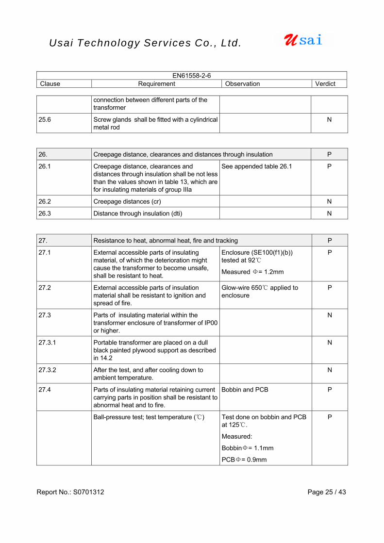
connection between different parts of the transformer
25.6 Screw glands shall be fitted with a cylindrical metal rod
N
26. Creepage distance, clearances and distances through insulation P
26.1 Creepage distance, clearances and distances through insulation shall be not less than the values shown in table 13, which are for insulating materials of group IIIa
See appended table 26.1 P
26.2 Creepage distances (cr) N
26.3 Distance through insulation (dti) N 27. Resistance to heat, abnormal heat, fire and tracking P
27.1 External accessible parts of insulating material, of which the deterioration might cause the transformer to become unsafe, shall be resistant to heat.
Enclosure (SE100(f1)(b)) tested at 92
Measured Φ= 1.2mm
P
27.2 External accessible parts of insulation material shall be resistant to ignition and spread of fire.
Glow-wire 650 applied to enclosure
P
27.3 Parts of insulating material within the transformer enclosure of transformer of IP00 or higher.
N
27.3.1 Portable transformer are placed on a dull black painted plywood support as described in 14.2
N
27.3.2 After the test, and after cooling down to ambient temperature.
N
27.4 Parts of insulating material retaining current carrying parts in position shall be resistant to abnormal heat and to fire.
Bobbin and PCB P
Ball-pressure test; test temperature () Test done on bobbin and PCB at 125.
Measured:
BobbinΦ= 1.1mm
PCBΦ= 0.9mm
P

EN61558-2-6 Clause Requirement Observation Verdict
Report No.: S0701312 Page 26 / 43
Usai Technology Serv ices Co., Ltd.
Glow-wire test (850) for insulating material retaining external conductor terminals (if>0.5A)
N
- any flame or glowing of the specimen extinguish within 30 s of withdrawing the glow-wire
N
- no ignition of a single layer of tissue paper No glowing drops N
27.5 For transformers with an IP rating other than IPX0, insulating parts retaining current carrying parts in position shall have resistance to tracking corresponding to at least material group IIIa if they are exposed to excessive mositure or deposition of dirt in normal use.
N
28. Resistance to rusting P
Ferrous parts, the rusting of which might cause the transformer to become unsafe, shall be adequately protected against rusting
The iron core is varnished P
`
H ANNEX H, ELECTRONIC CIRCUITS (Only applicable to AC/DC series) P
H.15 Short-circuit and overload protection P
H.15.6 Circuits designed and applied so that fault conditions do not render the appliance unsafe
244Vac P
During and after each test: P
- temperature do not exceed values specified in table 3 of Cl.15
No temperature measured exceeded the values specified in table 3 of cl. 15.
P
- transformer complies with conditions specified in 15.1
P
If a conductor of a pcb becomes open circuited, the transformer is considered to have withstood the particular test, provided that all six conditions as specified are met
N
H15.7 Fault conditions a) to f) of B15.8 are not tested if the following conditions are met:
P
- electronic circuit is a low-power circuit as specified
P
- safety of the appliance as specified does N
EN61558-2-6 Clause Requirement Observation Verdict
Report No.: S0701312 Page 27 / 43
Usai Technology Serv ices Co., Ltd.
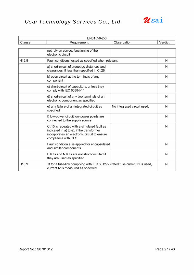
not rely on correct functioning of the electronic circuit
H15.8 Fault conditions tested as specified when relevant: N
a) short-circuit of creepage distances and clearances, if less than specified in Cl.26
N
b) open circuit at the terminals of any component
N
c) short-circuit of capacitors, unless they comply with IEC 60384-14
N
d) short-circuit of any two terminals of an electronic component as specified
N
e) any failure of an integrated circuit as specified
No integrated circuit used. N
f) low-power circuit:low-power points are connected to the supply source
N
Cl.15 is repeated with a simulated fault as indicated in a) to e), if the transformer incorporates an electronic circuit to ensure compliance with Cl.15
N
Fault condition e) is applied for encapsulated and similar components
N
PTC’s and NTC’s are not short-circuited if they are used as specified
N
H15.9 `If for a fuse-link complying with IEC 60127-3 rated fuse current I1 is used, current I2 is measured as specified:
N
Report No.: S0701312 Page 28 / 43
Usai Technology Serv ices Co., Ltd.
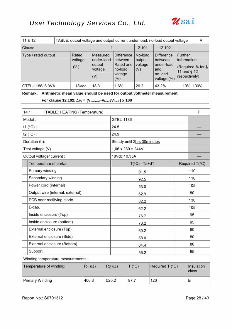
14.1 TABLE: HEATING (Temperature) P
Model : GTEL-1186 ⎯
t1 (°C) : 24.5 ⎯
t2 (°C) : 24.9 ⎯
Duration (h): Steady until 3hrs 30minutes ⎯
Test voltage (V) : 1,06 x 230 = 244V ⎯
Output voltage/ current : 18Vdc / 0.35A ⎯
Temperature of part/at: T(°C) =Ta+dT Required T(°C)
Primary winding 91.5 110
Secondary winding 92.5 110
Power cord (internal) 53.0 105
Output wire (internal, external) 62.9 80
PCB near rectifying diode 82.2 130
E-cap. 62.2 105
Inside enclosure (Top) 76.7 95
Inside enclosure (bottom) 73.2 95
External enclosure (Top) 60.2 80
External enclosure (Side) 58.0 80
External enclosure (Bottom) 64.4 80
Support 55.2 85
Winding temperature measurements:
Temperature of winding: R1 (Ω)
R2 (Ω) T (°C) Required T (°C) Insulation class
Primary Winding 406.3 520.2 97.7 120 B
11 & 12 TABLE: output voltage and output current under load; no-load output voltage P
Clause 11 12.101 12.102
Type / rated output Rated voltage
(V )
Measured under-load output voltage
(V)
Difference between Rated and no-load voltage (%)
No-load output voltage (V)
Difference between under-load and no-load voltage (%)
Further information
(Required % for § 11 and § 12 respectively)
GTEL-1186/ 6.3VA 18Vdc 18.3 1.6% 26.2 43.2% 10%; 100%
Remark: Arithmetic mean value should be used for output voltmeter measurement.
For clause 12.102, Δ% = (Vno-load -Vload /Vload ) x 100
Report No.: S0701312 Page 29 / 43
Usai Technology Serv ices Co., Ltd.
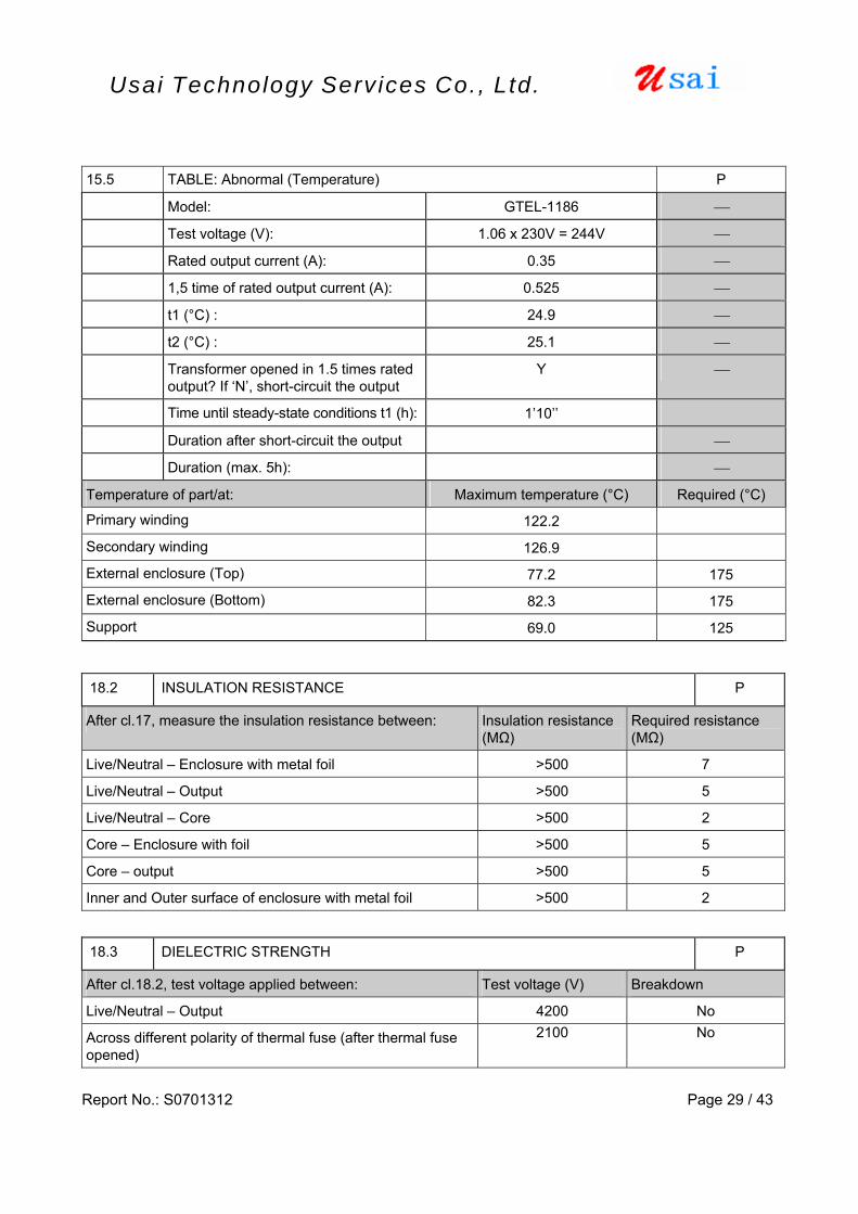
15.5 TABLE: Abnormal (Temperature) P
Model: GTEL-1186 ⎯
Test voltage (V): 1.06 x 230V = 244V ⎯
Rated output current (A): 0.35 ⎯
1,5 time of rated output current (A): 0.525 ⎯
t1 (°C) : 24.9 ⎯
t2 (°C) : 25.1 ⎯
Transformer opened in 1.5 times rated output? If ‘N’, short-circuit the output
Y ⎯
Time until steady-state conditions t1 (h): 1’10’’
Duration after short-circuit the output ⎯
Duration (max. 5h): ⎯
Temperature of part/at: Maximum temperature (°C) Required (°C)
Primary winding 122.2
Secondary winding 126.9
External enclosure (Top) 77.2 175
External enclosure (Bottom) 82.3 175
Support 69.0 125
18.2 INSULATION RESISTANCE P
After cl.17, measure the insulation resistance between: Insulation resistance (MΩ)
Required resistance (MΩ)
Live/Neutral – Enclosure with metal foil >500 7
Live/Neutral – Output >500 5
Live/Neutral – Core >500 2
Core – Enclosure with foil >500 5
Core – output >500 5
Inner and Outer surface of enclosure with metal foil >500 2
18.3 DIELECTRIC STRENGTH P
After cl.18.2, test voltage applied between: Test voltage (V) Breakdown
Live/Neutral – Output 4200 No
Across different polarity of thermal fuse (after thermal fuse opened)
2100 No

Report No.: S0701312 Page 30 / 43
Usai Technology Serv ices Co., Ltd.
Live/Neutral – Core 4200 No
Core - Enclosure 2100 No
Live/Neutral – Enclosure 4200 No
One layer insulation tape 2100 No
Table 20 Components list
Object/part No.
Manufacturer/ trademark Type / model Technical data Approvals
Enclosure GE PLASTICS AMERICAS SE100(f1)(b) 95°C, V-1 UL:E121562
Bobbin E.I. Dupont De Nemours & Co., Ltd.
101F/ 101L Polyamide 66, 130°C, V-0
UL:E41938
XINGNING JINYAN ELECTRICAL CO LTD
UEW 130°C UL:E238500
Windings BOLUO XIN LONG ELECTRICIAN DATA CO
UEWF 155°C UL:E229423
Thermal cutoff Aupo Electronics Ltd A4-1A 1A, 250V, 130°C VDE Xinya Electronic Co., Ltd 1672 PVC insulated wire,
Single conductor AWG22, 300V, 105°C
UL:E170689 Lead Wire
ZHONG SHAN YONG ROI ELECTRIC FACTORY CO LTD
1672 PVC insulated wire, Single conductor AWG22, 300V, 105°C
UL:E204893
Plug portion Guang Jian Electric Factory SE-1 2.5A, 250V TŰV R50051747
SEC wiring KAI TAT INDUSTRIES CO
2468 UL:E170689
Various 2468
PVC insulated, Flat Ribbon cable, Two conductors AWG22, 300V, 80°C, VW-1 Length: 1.8m
UL
Insulation tape Jingjang Yahua Pressure Sensitive Glue Co, Ltd
PZ,WF
Polyethylene terephthalate 130°C
UL:165111
Crossover Jingjang Yahua Pressure Sensitive Glue Co, Ltd
PZ,WF
Polyethylene terephthalate 130°C
UL:165111
PCB Various Various Min. 105°C, V-2 UL
Diode Various IN4001 -- --
Capacitor Various -- 1000uF, 35V -

Report No.: S0701312 Page 31 / 43
Usai Technology Serv ices Co., Ltd.
27.1, 27.4 Ball Pressure Test P
Part Test Temperature (°C) Sample Impression diameter (mm)
Transformer bobbin 125, -- 1.1
Enclosure 87+40=127 -- 1.2
PCB 125 -- 0.9
27.2, 27.4 Glow-Wire Test P
Enclosure: 650°C Result: P (no flame, no drops)
H15.7 LOW POWER POINT MEASUREMENT -
Location Measured Deliverable Power after 5s
Remark: Conduct under rated voltage. Readings are taken at 5s after applied the load.
P
Test Result Model
Voltage (V) Current (A) Power (W)
GTEL-1186 26.2 2.4 11.5
Table 26.1 Creepage distances and clearances
Cl measure (mm) Cl limited (mm) Cr measure (mm) Cr limited (mm)
Primary to secondary winding 10.8 5.5 10.8 6.0
Primary winding to secondary
circuit on PCB 6.2 5.5 6.2 6.0
Between thermal link leads 3.1 3.0 3.1 3.0
Primary to Core 6.1 5.5 6.1 6.0
Primary to external accessible
surface of enclosure 9.0 5.5 9.0 6.0
Report No.: S0701312 Page 32 / 43
Usai Technology Serv ices Co., Ltd.
Photo Document

Report No.: S0701312 Page 33 / 43
Usai Technology Serv ices Co., Ltd.
Fig.1 overall view
Fig.2 Bottom view
Report No.: S0701312 Page 34 / 43
Usai Technology Serv ices Co., Ltd.
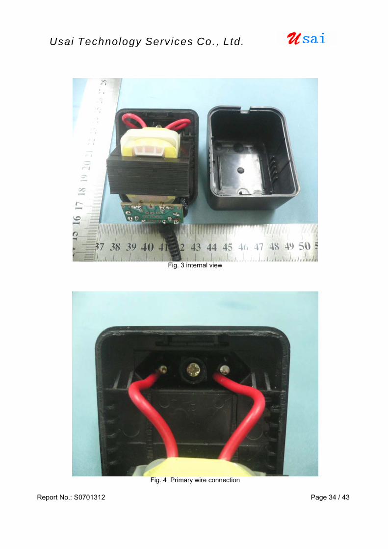
Fig. 3 internal view
Fig. 4 Primary wire connection

Report No.: S0701312 Page 35 / 43
Usai Technology Serv ices Co., Ltd.
Fig. 5 PCB trace view
Fig. 6 PCB layout view

Report No.: S0701312 Page 36 / 43
Usai Technology Serv ices Co., Ltd.
Fig. 7 Bobbin and insulation tape
Fig. 8 Primary winding
Report No.: S0701312 Page 37 / 43
Usai Technology Serv ices Co., Ltd.
Transformer specification